KR101028748B1 - Large wind power generator - Google Patents
Large wind power generatorDownload PDFInfo
- Publication number
- KR101028748B1 KR101028748B1KR1020080080365AKR20080080365AKR101028748B1KR 101028748 B1KR101028748 B1KR 101028748B1KR 1020080080365 AKR1020080080365 AKR 1020080080365AKR 20080080365 AKR20080080365 AKR 20080080365AKR 101028748 B1KR101028748 B1KR 101028748B1
- Authority
- KR
- South Korea
- Prior art keywords
- rotating
- shaft
- power
- generator
- wind
- Prior art date
- Legal status (The legal status is an assumption and is not a legal conclusion. Google has not performed a legal analysis and makes no representation as to the accuracy of the status listed.)
- Expired - Fee Related
Links
Images


Classifications
- F—MECHANICAL ENGINEERING; LIGHTING; HEATING; WEAPONS; BLASTING
- F03—MACHINES OR ENGINES FOR LIQUIDS; WIND, SPRING, OR WEIGHT MOTORS; PRODUCING MECHANICAL POWER OR A REACTIVE PROPULSIVE THRUST, NOT OTHERWISE PROVIDED FOR
- F03D—WIND MOTORS
- F03D80/00—Details, components or accessories not provided for in groups F03D1/00 - F03D17/00
- F03D80/50—Maintenance or repair
- F—MECHANICAL ENGINEERING; LIGHTING; HEATING; WEAPONS; BLASTING
- F03—MACHINES OR ENGINES FOR LIQUIDS; WIND, SPRING, OR WEIGHT MOTORS; PRODUCING MECHANICAL POWER OR A REACTIVE PROPULSIVE THRUST, NOT OTHERWISE PROVIDED FOR
- F03D—WIND MOTORS
- F03D7/00—Controlling wind motors
- F03D7/02—Controlling wind motors the wind motors having rotation axis substantially parallel to the air flow entering the rotor
- F03D7/022—Adjusting aerodynamic properties of the blades
- F03D7/024—Adjusting aerodynamic properties of the blades of individual blades
- F—MECHANICAL ENGINEERING; LIGHTING; HEATING; WEAPONS; BLASTING
- F03—MACHINES OR ENGINES FOR LIQUIDS; WIND, SPRING, OR WEIGHT MOTORS; PRODUCING MECHANICAL POWER OR A REACTIVE PROPULSIVE THRUST, NOT OTHERWISE PROVIDED FOR
- F03D—WIND MOTORS
- F03D7/00—Controlling wind motors
- F03D7/02—Controlling wind motors the wind motors having rotation axis substantially parallel to the air flow entering the rotor
- F03D7/0272—Controlling wind motors the wind motors having rotation axis substantially parallel to the air flow entering the rotor by measures acting on the electrical generator
- F—MECHANICAL ENGINEERING; LIGHTING; HEATING; WEAPONS; BLASTING
- F03—MACHINES OR ENGINES FOR LIQUIDS; WIND, SPRING, OR WEIGHT MOTORS; PRODUCING MECHANICAL POWER OR A REACTIVE PROPULSIVE THRUST, NOT OTHERWISE PROVIDED FOR
- F03D—WIND MOTORS
- F03D7/00—Controlling wind motors
- F03D7/02—Controlling wind motors the wind motors having rotation axis substantially parallel to the air flow entering the rotor
- F03D7/028—Controlling wind motors the wind motors having rotation axis substantially parallel to the air flow entering the rotor controlling wind motor output power
- F—MECHANICAL ENGINEERING; LIGHTING; HEATING; WEAPONS; BLASTING
- F05—INDEXING SCHEMES RELATING TO ENGINES OR PUMPS IN VARIOUS SUBCLASSES OF CLASSES F01-F04
- F05B—INDEXING SCHEME RELATING TO WIND, SPRING, WEIGHT, INERTIA OR LIKE MOTORS, TO MACHINES OR ENGINES FOR LIQUIDS COVERED BY SUBCLASSES F03B, F03D AND F03G
- F05B2270/00—Control
- F05B2270/30—Control parameters, e.g. input parameters
- F05B2270/32—Wind speeds
- Y—GENERAL TAGGING OF NEW TECHNOLOGICAL DEVELOPMENTS; GENERAL TAGGING OF CROSS-SECTIONAL TECHNOLOGIES SPANNING OVER SEVERAL SECTIONS OF THE IPC; TECHNICAL SUBJECTS COVERED BY FORMER USPC CROSS-REFERENCE ART COLLECTIONS [XRACs] AND DIGESTS
- Y02—TECHNOLOGIES OR APPLICATIONS FOR MITIGATION OR ADAPTATION AGAINST CLIMATE CHANGE
- Y02E—REDUCTION OF GREENHOUSE GAS [GHG] EMISSIONS, RELATED TO ENERGY GENERATION, TRANSMISSION OR DISTRIBUTION
- Y02E10/00—Energy generation through renewable energy sources
- Y02E10/70—Wind energy
- Y02E10/72—Wind turbines with rotation axis in wind direction
- Y—GENERAL TAGGING OF NEW TECHNOLOGICAL DEVELOPMENTS; GENERAL TAGGING OF CROSS-SECTIONAL TECHNOLOGIES SPANNING OVER SEVERAL SECTIONS OF THE IPC; TECHNICAL SUBJECTS COVERED BY FORMER USPC CROSS-REFERENCE ART COLLECTIONS [XRACs] AND DIGESTS
- Y02—TECHNOLOGIES OR APPLICATIONS FOR MITIGATION OR ADAPTATION AGAINST CLIMATE CHANGE
- Y02P—CLIMATE CHANGE MITIGATION TECHNOLOGIES IN THE PRODUCTION OR PROCESSING OF GOODS
- Y02P70/00—Climate change mitigation technologies in the production process for final industrial or consumer products
- Y02P70/50—Manufacturing or production processes characterised by the final manufactured product
Landscapes
- Engineering & Computer Science (AREA)
- Life Sciences & Earth Sciences (AREA)
- Sustainable Development (AREA)
- Sustainable Energy (AREA)
- Chemical & Material Sciences (AREA)
- Combustion & Propulsion (AREA)
- Mechanical Engineering (AREA)
- General Engineering & Computer Science (AREA)
- Physics & Mathematics (AREA)
- Fluid Mechanics (AREA)
- Wind Motors (AREA)
Abstract
Translated fromKoreanDescription
Translated fromKorean본 발명은 대형 풍력발전기에 관한 것으로서, 더욱 상세하게는 날개가 부착되어 회전되는 회전판의 외주연에 다수개의 피니언 기어가 원주방향으로 형성되고, 상기 피니언 기어에 축으로 연결되어 다수개의 소형 제너레이터가 설치됨으로써, 바람의 풍속에 따라 제너레이터의 작동개수를 조절할 수 있어 풍속발전기의 효율이 증가되고, 종래에서 대형의 풍력발전기에 사용되는 대형 제너레이터에 따른 제작비용이 절감되며, 상기 제너레이터의 고장시, 수리 및 교체에 따른 풍력발전기의 작동을 정지할 필요가 없어 사용할 수 있고, 상기 날개를 'V' 형태로 배치됨으로써, 날개가 회전시 수직과 수평 위치에 위치함으로써 수평으로 불어오는 바람과 상하로 불어오는 바람을 이용할 수 있는 대형 풍력발전기에 관한 것이다.The present invention relates to a large wind power generator, and more particularly, a plurality of pinion gears are formed in the circumferential direction on the outer circumference of the rotating plate to which the blades are attached and rotated, and a plurality of small generators are connected to the pinion gears in an axial direction. By doing so, the number of generators can be adjusted according to the wind speed, so that the efficiency of the wind speed generator is increased, and the manufacturing cost according to the large size generator used in the large wind power generator is conventionally reduced. It can be used without needing to stop the operation of the wind turbine according to the replacement, and by placing the wing in the 'V' shape, the wind is blowing horizontally and the wind blowing up and down by positioning the wing in the vertical and horizontal position when rotating It relates to a large wind power generator that can be used.
일반적으로, 풍력발전기는, 무한정, 무비용의 청정에너지원인 바람을 이용하여 발전할 수 있는 장치로서 발전원별 전력생산단가의 가격경쟁력 향상 및 발전시스템 설치의 소요면적 최소화 등과 같은 원가적측면과, 화석에너지 고갈에 대한 대체에너지원과 지구환경보호라는 사회환경적측면과, 더불어 공급의 안정성, 에너지 수입의 의존도 감소라는 경제적측면을 얻을 수 있기 때문에 보급의 가속화가 일고 있다.In general, the wind power generator is an apparatus capable of generating power using the wind, which is a clean energy source for uninterrupted use, and has a cost aspect such as improving the price competitiveness of the power generation unit cost by each power source and minimizing the required area of the power generation system, and fossils. It is accelerating its spread because it provides economic and social aspects such as alternative energy sources and environmental protection for energy depletion, as well as economic stability such as supply stability and reduced dependence on energy imports.
상기 풍력발전기는 바람에 의하여 회전하는 날개에 의하여 발전기의 축을 회전시켜 동력(전기)을 발전시키는 것이다.The wind generator generates power (electricity) by rotating the shaft of the generator by a blade that is rotated by the wind.
그 중에서 본 발명의 풍력발전기는 건물의 옥상 등에 설치되는 것으로 대형(大型)화 된 풍력발전기에 대한 것이다.Among them, the wind power generator of the present invention is installed on a rooftop of a building, and the like, and a large sized wind power generator.
종래의 대형 풍력발전기는 바람에 의해 회전되는 대형 날개와, 상기 날개를 지지하는 회전판과, 상기 회전판의 중방부에 설치되는 회전축과, 상기 회전축을 지지하는 몸통으로 구성된다.Conventional large wind turbines are composed of a large blade that is rotated by the wind, a rotating plate for supporting the blade, a rotating shaft provided in the middle portion of the rotating plate, and a body for supporting the rotating shaft.
여기서, 상기 날개의 회전력을 동력으로 발전시키도록 발전기(generator)가 회전축에 직접 연결되거나, 또는 기어, 벨트, 체인과 같은 동력을 전달하는 동력전달장치에 간접적으로 연결된다. 이때, 상기 발전기는 대형 풍력발전기에 맞춰 대형으로 별도 제작하는 것이다.Here, the generator (generator) is directly connected to the rotating shaft or indirectly connected to the power transmission device for transmitting power, such as gears, belts, chains to generate the rotational force of the blades to power. At this time, the generator is to produce a separate large in accordance with the large wind power generator.
그런데, 상기 대형의 풍력발전기에 사용되는 대형 발전기는 별도로 제작하기 위해 엄청난 제작비용이 소요되고, 제작된 발전기의 운송 및 설치에 따른 시간과 인력에 따른 설치비용이 증가하는 문제점이 발생한다.By the way, the large generator used in the large wind generator takes a huge production cost to produce separately, the installation cost according to the time and manpower according to the transportation and installation of the produced generator occurs.
또한, 상기 대형 제너레이터의 고장시, 수리 및 교체에 따라 풍력발전기의 작동을 정지시켜야하므로 써 풍력발전기의 효율이 떨어지는 큰 문제점이 발생한다.In addition, when the large generator breaks down, it is necessary to stop the operation of the wind turbine according to repair and replacement, thereby causing a large problem in that the efficiency of the wind turbine falls.
따라서, 본 발명은 상기 종래의 문제점을 해소하기 위해 안출된 것으로서,SUMMARY OF THE INVENTION Accordingly, the present invention has been made keeping in mind the above problems occurring in the prior art,
날개가 부착되어 회전되는 회전판의 외주연에 다수개의 피니언 기어가 원주방향으로 형성되고, 상기 피니언 기어에 축으로 연결되어 다수개의 소형 제너레이터가 설치됨으로써, 바람의 풍속에 따라 제너레이터의 작동개수를 조절할 수 있어 풍속발전기의 효율이 증가되고, 종래에서 대형의 풍력발전기에 사용되는 대형 제너레이터에 따른 제작비용이 절감되며, 상기 제너레이터의 고장시, 수리 및 교체에 따른 풍력발전기의 작동을 정지할 필요가 없어 사용할 수 있고, 상기 날개를 'V' 형태로 배치됨으로써, 날개가 회전시 수직과 수평 위치에 위치함으로써 수평으로 불어오는 바람과 상하로 불어오는 바람을 이용할 수 있는 대형 풍력발전기를 제공하는데 목적이 있다.A plurality of pinion gears are formed in the circumferential direction on the outer circumference of the rotating plate to which the blade is attached and rotated, and a plurality of small generators are connected to the pinion gears to be installed in the circumferential direction, so that the number of generators can be adjusted according to the wind speed. Therefore, the efficiency of the wind speed generator is increased, and the manufacturing cost according to the large generator used in the large wind power generator is conventionally reduced, and when the generator fails, there is no need to stop the operation of the wind generator according to the repair and replacement. It is possible to provide a large wind power generator capable of utilizing the wind blowing horizontally and the wind blowing up and down by positioning the wing in the 'V' form, the wing is located in the vertical and horizontal position when rotating.
상기 목적을 달성하고자, 본 발명은 바람에 의해 날개가 회전되어 동력(전력)을 발전시키는 대형 풍력발전기에 있어서,In order to achieve the above object, the present invention is a large wind turbine that rotates the blades by the wind to generate power (power),
중심부분에 수직으로 설치되는 지지축이 형성되는 지지대와;A support having a support shaft installed perpendicularly to the central portion;
상기 지지대의 지지축 상부에 설치되는 몸체와;A body installed above the support shaft of the support;
상기 날개가 외주연에 고정 설치되고 끝단부가 몸체의 일단면에 결합되는 회전축과, 상기 회전축이 중앙부에 관통되도록 홀이 형성되고 상기 회전축의 회전동 력에 의해 회전되는 회전판으로 이루어지는 회전부와;A rotating part including a rotating shaft fixed to the outer circumference and having an end portion coupled to one end surface of the body, and a rotating plate having a hole formed therein so that the rotating shaft penetrates to a central portion thereof and rotated by rotational power of the rotating shaft;
상기 회전판의 외주연에 원주방향으로 다수개가 접촉 설치되어 회전되고, 중앙부에 축이 형성되어 상기 회전판의 회전동력을 전달하는 피니언 기어와;A pinion gear configured to rotate in contact with the outer circumference of the rotating plate in a circumferential direction, the shaft being formed in the center thereof to transmit rotational power of the rotating plate;
상기 다수개의 피니언 기어 중 어느 하나 이상에 축으로 연결되어 상기 피니언 기어를 임의로 회전시켜 멈춰있는 회전판을 스타트시켜주는 모터부와;A motor unit connected to any one or more of the plurality of pinion gears by a shaft to arbitrarily rotate the pinion gear to start the rotating plate;
상기 모터부가 설치된 피니언 기어 이외의 다수개 피니언 기어에 축으로 연결되어 바람에 의해 회전하는 회전판의 회전동력을 전달받아 발전시키는 발전장치와;A power generator connected to a plurality of pinion gears other than the pinion gear in which the motor unit is installed, and generating power by receiving rotational power of a rotating plate rotated by wind;
상기 회전축의 회전수(RPM)와 외부의 바람속도를 감지하도록 설치된 센서의 측정값을 신호로 전달받아 사용자의 설정된 값에 의해 다수개의 발전장치를 제어하도록 외부에 설치되는 제어장치;를 포함하여 구성되는 것을 특징으로 하는 대형 풍력발전기에 관한 것이다.And a controller installed outside to control a plurality of power generation apparatuses by a user's set value by receiving a signal of a sensor installed to detect the rotational speed of the rotating shaft and an external wind speed as a signal. It relates to a large wind power generator characterized in that.
이상에서 살펴 본 바와 같이, 본 발명의 대형 풍력발전기는 날개가 부착되어 회전되는 회전판의 외주연에 다수개의 피니언 기어가 원주방향으로 형성되고, 상기 피니언 기어에 축으로 연결되어 다수개의 소형 제너레이터가 설치됨으로써, 바람의 풍속에 따라 제너레이터의 작동개수를 조절할 수 있어 풍속발전기의 효율이 증가되고, 종래에서 대형의 풍력발전기에 사용되는 대형 제너레이터에 따른 제작비용이 절감되며, 상기 제너레이터의 고장시, 수리 및 교체에 따른 풍력발전기의 작동을 정지할 필요가 없어 사용할 수 있는 효과가 있다.As described above, in the large wind turbine of the present invention, a plurality of pinion gears are formed in the circumferential direction on the outer circumference of the rotating plate to which the blades are attached and rotated, and a plurality of small generators are connected to the pinion gears in an axial direction. By doing so, the number of generators can be adjusted according to the wind speed, so that the efficiency of the wind speed generator is increased, and the manufacturing cost according to the large size generator used in the large wind power generator is conventionally reduced. There is no need to stop the operation of the wind turbine according to the replacement has an effect that can be used.
또한, 본 발명은 날개를 'V' 형태로 배치됨으로써, 날개가 회전시 수직과 수평 위치에 위치함으로써 수평으로 불어오는 바람과 상하로 불어오는 바람을 이용할 수 있는 장점이 있다.In addition, the present invention has the advantage that by placing the wing in the 'V' shape, the wind is blowing horizontally and the wind blowing up and down by being positioned in the vertical and horizontal position when the wing is rotated.
본 발명은 상기의 목적을 달성하기 위해 아래와 같은 특징을 갖는다.The present invention has the following features to achieve the above object.
본 발명은 바람에 의해 날개가 회전되어 동력(전력)을 발전시키는 대형 풍력발전기에 있어서,The present invention is a large wind power generator in which the blade is rotated by the wind to generate power (power),
중심부분에 수직으로 설치되는 지지축이 형성되는 지지대와;A support having a support shaft installed perpendicularly to the central portion;
상기 지지대의 지지축 상부에 설치되는 몸체와;A body installed above the support shaft of the support;
상기 날개가 외주연에 고정 설치되고 끝단부가 몸체의 일단면에 결합되는 회전축과, 상기 회전축이 중앙부에 관통되도록 홀이 형성되고 상기 회전축의 회전동력에 의해 회전되는 회전판으로 이루어지는 회전부와;A rotating shaft including a rotating shaft fixed to the outer circumference and having an end portion coupled to one end surface of the body, and a rotating plate having a hole formed therein so that the rotating shaft penetrates to a central portion thereof and rotated by the rotating power of the rotating shaft;
상기 회전판의 외주연에 원주방향으로 다수개가 접촉 설치되어 회전되고, 중앙부에 축이 형성되어 상기 회전판의 회전동력을 전달하는 피니언 기어와;A pinion gear configured to rotate in contact with the outer circumference of the rotating plate in a circumferential direction, the shaft being formed in the center thereof to transmit rotational power of the rotating plate;
상기 다수개의 피니언 기어 중 어느 하나 이상에 축으로 연결되어 상기 피니언 기어를 임의로 회전시켜 멈춰있는 회전판을 스타트시켜주는 모터부와;A motor unit connected to any one or more of the plurality of pinion gears by a shaft to arbitrarily rotate the pinion gear to start the rotating plate;
상기 모터부가 설치된 피니언 기어 이외의 다수개 피니언 기어에 축으로 연결되어 바람에 의해 회전하는 회전판의 회전동력을 전달받아 발전시키는 발전장치 와;A power generator connected to a plurality of pinion gears other than the pinion gear in which the motor unit is installed, and generating power by receiving rotational power of a rotating plate rotated by wind;
상기 회전축의 회전수(RPM)와 외부의 바람속도를 감지하도록 설치된 센서의 측정값을 신호로 전달받아 사용자의 설정된 값에 의해 다수개의 발전장치를 제어하도록 외부에 설치되는 제어장치;를 포함하여 구성되는 것을 특징으로 한다.And a controller installed outside to control a plurality of power generation apparatuses by a user's set value by receiving a signal of a sensor installed to detect the rotational speed of the rotating shaft and an external wind speed as a signal. It is characterized by.
이와 같은 특징을 갖는 본 발명은 그에 따른 바람직한 실시예를 통해 더욱 명확히 설명될 수 있을 것이다.The present invention having such characteristics can be more clearly described by the preferred embodiments thereof.
이하 첨부된 도면을 참조로 본 발명의 바람직한 실시예를 상세히 설명하도록 한다. 이에 앞서, 본 명세서 및 청구범위에 사용된 용어나 단어는 통상적이거나 사전적인 의미로 한정해서 해석되어서는 아니되며, 발명자는 그 자신의 발명을 가장 최선의 방법으로 설명하기 위해 용어의 개념을 적절하게 정의할 수 있다는 원칙에 입각하여 본 발명의 기술적 사상에 부합하는 의미와 개념으로 해석되어야만 한다.Hereinafter, exemplary embodiments of the present invention will be described in detail with reference to the accompanying drawings. Prior to this, terms or words used in the specification and claims should not be construed as having a conventional or dictionary meaning, and the inventors should properly explain the concept of terms in order to best explain their own invention. Based on the principle that can be defined, it should be interpreted as meaning and concept corresponding to the technical idea of the present invention.
따라서, 본 명세서에 기재된 실시예와 도면에 도시된 구성은 본 발명의 가장 바람직한 일실시예에 불과할 뿐이고 본 발명의 기술적 사상을 모두 대변하는 것은 아니므로, 본 출원시점에 있어서 이들을 대체할 수 있는 다양한 균등물과 변형예들이 있을 수 있음을 이해하여야 한다.Therefore, the embodiments described in the specification and the drawings shown in the drawings are only one of the most preferred embodiments of the present invention and do not represent all of the technical idea of the present invention, various modifications that can be replaced at the time of the present application It should be understood that there may be equivalents and variations.
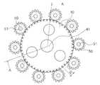
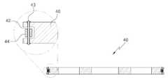
도 1은 본 발명의 일실시예에 따른 대형 풍력발전기를 나타낸 설치 상태도이고, 도 2는 본 발명의 제 2실시예에 따른 회건물에 설치되는 대형 풍력발전기를 나타낸 설치 상태도이고, 도 3은 본 발명의 일실시예에 따른 회전판과 피니언 기어를 나타낸 평면도이고, 도 4는 도 3의 A-A 부분을 나타낸 단면 확대도이다.1 is an installation state diagram showing a large wind power generator according to an embodiment of the present invention, Figure 2 is an installation state diagram showing a large wind power generator is installed in the building according to the second embodiment of the present invention, Figure 3 4 is a plan view illustrating a rotating plate and a pinion gear according to an embodiment of the present invention, and FIG. 4 is an enlarged cross-sectional view of the AA part of FIG. 3.
도 1과 도 2에 도시한 바와 같이, 본 발명의 대형 풍력발전기(100)는 일반적으로 설치되는 언덕이나 산 중턱 또는 고지대에 설치되거나 고층건물(B)에 설치되어 바람에 의해 날개를 회전시켜 거기서 발생하는 회전동력을 발전시키도록 지지대(10)와, 몸체(20)와, 날개(30)와, 회전부과, 피니언 기어(50)와, 모터부(60)와, 발전장치(70), 제어장치(90)로 구성된다.As shown in Figures 1 and 2, the
상기 지지대(10)는 건물(B)의 옥상에 앙카볼트와 같은 체결볼트에 견고하게 고정설치되는 것으로 중심부분에는 수직으로 설치되는 지지축(11)과, 상기 날개(30)의 회전에 의해 가중되는 하중이 하측으로 전달되는 충격을 흡수하도록 탄성부재(12)가 더 설치된다.The
상기 몸체(20)는 도 1에 도시한 바와 같이, 내부가 중공되어 모터부(60)와 발전장치(70)가 내부에 구비되고, 상기 몸체(20)는 수평으로 이루어져 바람이 부는 방향으로 날개(30)가 향하도록 외부면이 곡선으로 이루어진다. 또는 도 2에 도시한 바와 같이, 상기 몸체(20)는 상기 날개(30)를 소정의 각도로 기울어지게 설치할 수 있도록 임의의 각도(β)로 구부러지도록 형성되며, 상기 지지대(10)의 상부에 설치되되, 몸체(20)와 지지대(10) 사이에는 수직선(C)를 중심으로 회전하도록 베어링(미도시)이 설치된다.As shown in FIG. 1, the
여기서, 상기 몸체(20)의 구부러진 각도(β)는 보통 40 ~ 50도이며, 바람직하게는 날개(30)가 수직선(C)과 45도로 기울어지게 설치될 수 있도록 상기 몸체(20)의 구부러진 각도(β)도 45도로 이루어지는 것이 바람직하다.Here, the bent angle (β) of the
또한, 상기 몸체(20)의 내부는 중공되어 상기 발전장치(70)와 모터부(60)가 내부에 구비되고, 상기 몸체(20)의 끝단부를 통해 발전장치(70)와 모터부(60)가 착탈할 수 있도록 몸체(20)의 내부를 개폐하는 개폐판(21)으로 이루어진다.In addition, the inside of the
상기 날개(30)는 일반적으로 수평으로 불어오는 바람에 영향을 받아 회전되도록 형성되거나 바람에 의해 회전시 수직과 수평방향으로 위치되는 'V'자 형태로 형성되어 상기 회전판(40)에 고정 설치되고, 상기 날개(30)는 바람에 의해 회전하는 동력용 날개와, 방향의 위치를 조절하는 방향조절용 날개로 이루어진다.The
여기서, 상기 날개(30)는 'V'자 형태로 설치되는 블레이드(하나의 날개)와 블레이드의 설치각도(θ)는 보통 70 ~ 110도 이루어지며, 본 발명에서의 바람직하게는 85 ~ 95도 사이가 적당하다.Here, the
이때, 상기 날개(30)는 본 발명과 동일한 특허권자가 출원한(출원번호 : 10-2008-0070486, 명칭 : 건물형 풍력발전기) 발명과 동일한 구성, 구조, 원리이기에 별도의 기술은 더 하지 않는다.At this time, the
상기 회전부(미도시)는 회전축(40)과 회전판(41)으로 구성되는데, 상기 회전판(40)은 날개(30)가 일단면에 고정 설치되어 날개(30)의 회전에 의해 구동하고, 상기 회전판(40)의 중앙부에 회전축(41)이 설치되어 회전축(41)을 중심으로 회전판(40)이 회전하며, 상기 회전축(41)은 몸체(20)의 끝단부(개폐판) 중앙부에 관통 설치된다. 여기서, 상기 회전축(41)의 끝단부에는 외주면에 원주방향으로 일정간격 이격되어 다수개의 날개(30)가 일체형으로 고정 설치된다.The rotating part (not shown) is composed of a
이때, 상기 날개(30)가 원활하게 회전할 수 있도록 몸체(20)의 끝단부와 회전판(40)의 회전축(41) 사이에는 베어링(미도시)이 설치된다.At this time, a bearing (not shown) is installed between the end of the
여기서, 상기 회전판(40)의 외주연에는 도 4을 참고하여, 원주방향으로 하나의 삽입홈(42)이 형성되고, 상기 삽입홈(42)에 피니언 기어(50)가 맞물려지도록 상기 회전판(40)의 일단면에 핀(43)이 설치되고, 상기 핀(43)은 삽입홈(42)을 관통하여 설치되며, 상기 핀(43)이 회전판(40)의 일단면에서 원주방향으로 일정 피치(P)로 이격되어 다수개가 형성된다. 다시 말해, 상기 다수개의 핀(43)은 각각 삽입홈(42)과 직각으로 설치되는 것이다.Here, with reference to FIG. 4, one
그리고, 상기 핀(43)의 외주연에는 삽입홈(42)에 설치된 핀(43)과 상기 피니언 기어(50)의 나사산이 맞물릴 시, 원활하게 접촉되도록 롤러(44)가 더 결합된다.In addition, the
상기 피니언 기어(50)는 회전판(40)의 외주연에 형성된 핀(43)이 결합된 삽입홈(42)에 맞물려 회전되고, 상기 피니언 기어(50)는 회전판(40)의 외주연에 원주방향으로 일정간격 이격되어 다수개가 설치된다. 이때, 상기 피니언 기어(50)의 중앙부에는 축(51)이 피니언 기어(50)와 직각으로 설치되어 축(51)을 중심으로 회전된다.The
여기서, 상기 피니언 기어(50)는 일반적으로 공지된 피니언 기와와 유사한 구조,구성이기에 별도의 기술을 더 하지 않는다.Here, the
도 5는 본 발명의 일실시예에 따른 모터부를 나타낸 확대도이다. 도 5에 도시한 바와 같이, 상기 모터부(60)는 다수개의 피니언 기어(50) 중 어느 하나 이상에 선택적으로 설치되는데, 이유는 상기 피니언 기어(50)를 임의로 회전시켜 멈춰있는 회전판(40)을 스타트시켜주기 위해서다.5 is an enlarged view illustrating a motor unit according to an embodiment of the present invention. As shown in FIG. 5, the
여기서, 상기 모터부(60)는 피니언 기어(50)의 축(51)에 연결되어 피니언 기어(50)을 회전시키는 모터(61)와, 상기 피니언 기어(50)와 모터(61)를 연결하는 축에 설치되어 모터의 고속 회전력을 제어하는 감속기(62)로 구성된다.Here, the
이때, 상기 모터(61)와 감속기(62)는 하단부에 받침대(80)가 설치되어 고정되고, 상기 받침대(80)는 몸체(20)의 내부에 고정되는 것이다.At this time, the
도 6은 본 발명의 일실시예에 따른 발전장치를 나타낸 확대도이다. 도 6에 도시한 바와 같이, 상기 발전장치(70)는 상기 모터부(60)가 설치된 피니언 기어(하나 또는 두개) 이외의 나머지 다수개의 피니언 기어(50)에 형성된 축(51)과 연결되어 바람에 의해 회전하는 날개의 회전동력을 전달받아 발전한다.6 is an enlarged view illustrating a power generator according to an embodiment of the present invention. As shown in FIG. 6, the
여기서, 상기 발전장치(70)는 피니언 기어(50)의 축(51)에 연결되어 회전동력을 증속시키는 가속기(71)와, 상기 가속기(71)에서 연장된 축에 연결되어 가속기(71)를 통해 증속된 동력을 발전시키는 제너레이터(72)와, 상기 가속기(71)와 제너레이터(72)를 연결하는 축에 설치되어 상기 가속기(71)와 제너레이터(72)를 접촉/분리되도록 두 개로 형성되는 디스크(73)와, 상기 제너레이터(72)의 끝단부에 설치되어 압력에 의해 제너레이터(72)를 좌,우 이송시키는 유압실린더(74)로 구성된다.Here, the
이때, 상기 디스크(73)는 가속기(71)와 제너레이터(72)를 연결하는 축에 설치되어 상기 축을 나누어 끝단부에 디스크(73)가 각각 하나씩 설치되고, 상기 두 개의 디스크(73)가 접촉시, 접촉면에 형성된 디스크 기어(미도시)에 의해 맞물려져 가속기(71)의 회전동력을 제너레이터(72)에 전달하는 역할을 하며, 상기 두 개의 디스크(73)가 떨어질 시, 가속기(71)의 동력이 제너레이터(72)에 전달되지 않는다.At this time, the
그리고, 상기 가속기(71)와 제너레이터(72) 및 유압실린더(74)는 모터부(60)와 마찬가지로 하단부에 받침대(80)가 설치되어 지지되고, 상기 받침대(80)는 몸체(20)의 내부 일단부에 고정되는 것이다. 이때, 상기 제너레이터(72)가 부착된 받침대(80)에는 상기 제너레이터(72)가 유압실린더(74)에 의해 좌,우로 이송되도록 이송거리만큼의 지지홈(미도시)이 형성된다.In addition, the
추가적으로, 상기 날개(30)의 회전을 정지시키기 위해 상기 피니언 기어(50)의 축(51)에 브레이크장치(미도시)가 설치되어 축(51)의 회전을 서서히 줄여주어 최종 날개(30)를 정지시킨다.In addition, a brake device (not shown) is installed on the
여기서, 상기 유압실린더(74)에 의해 제너레이터(72)와 가속기(71)를 접촉/분리시키는 이유는 바람의 풍속에 맞춰 날개(30)의 회전동력이 발생하므로 발전시킬 제너레이터(72)의 수도 조절하는 것이다.Here, the reason for contacting / separating the
이렇듯, 바람의 풍속을 측정하여 제너레이터(72)의 수를 조절하도록 제어장치(90)가 설치되고, 상기 제어장치(90)는 유압실린더(74)를 제어하여 상기 제너레이터(72)를 접촉/분리시켜 수를 조절한다.As such, the
상기 제어장치(90)는 바람속도를 감지하여 측정하도록 센서(91)가 풍력발전기(100)의 최상측 또는 건물(B)의 옥상 등 다양한 곳에 설치가 가능하다.The
그리고, 상기 제어장치(90)는 회전축(41)의 회전수(RPM)를 감지하여 회전축(41)의 회전수에 따라 제너레이터(72)의 수를 조절하도록 상기 회전축(41)에 센 서(91)가 설치되고, 상기 각각의 센서(91)의 측정값은 제어장치(90)의 제어부에 신호로 전달되어 사용자가 설정한 값에 의해 다수개의 유압실린더(74)를 제어하는 원리이다.In addition, the
도 1은 본 발명의 일실시예에 따른 대형 풍력발전기를 나타낸 설치 상태도이고,1 is an installation state diagram showing a large wind power generator according to an embodiment of the present invention,
도 2는 본 발명의 제 2실시예에 따른 회건물에 설치되는 대형 풍력발전기를 나타낸 설치 상태도이고,2 is an installation state diagram showing a large wind power generator installed in the ash building according to the second embodiment of the present invention,
도 3은 본 발명의 일실시예에 따른 회전판과 피니언 기어를 나타낸 평면도이고,3 is a plan view showing a rotating plate and a pinion gear according to an embodiment of the present invention,
도 4는 도 3의 A-A 부분을 나타낸 단면 확대도이고,4 is an enlarged cross-sectional view illustrating a portion A-A of FIG. 3,
도 5는 본 발명의 일실시예에 따른 모터부를 나타낸 확대도이고,5 is an enlarged view showing a motor unit according to an embodiment of the present invention;
도 6은 본 발명의 일실시예에 따른 발전장치를 나타낸 확대도이다. 6 is an enlarged view illustrating a power generator according to an embodiment of the present invention.
<도면의 주요부분에 대한 부호의 설명><Description of the symbols for the main parts of the drawings>
10 : 지지대11 : 지지축10: support 11: support shaft
12 : 탄성부재20 : 몸체12: elastic member 20: body
21 : 개폐판30 : 날개21: opening and closing board 30: wing
40 : 회전판41 : 회전축40: rotating plate 41: rotating shaft
42 : 삽입홈43 : 핀42: insertion groove 43: pin
44 : 롤러50 : 피니언 기어44: roller 50: pinion gear
51 : 축60 : 모터부51
61 : 모터62 : 감속기61: motor 62: reducer
70 : 발전장치71 : 가속기70: generator 71: accelerator
72 : 제너레이터73 : 디스크72: generator 73: disk
74 : 유압실린더80 : 받침대74: hydraulic cylinder 80: pedestal
90 : 제어장치91 : 센서90: control device 91: sensor
100 : 대형 풍력발전기100: large wind power generator
Claims (6)
Translated fromKoreanApplications Claiming Priority (2)
| Application Number | Priority Date | Filing Date | Title |
|---|---|---|---|
| KR20080077775 | 2008-08-08 | ||
| KR1020080077775 | 2008-08-08 |
Publications (2)
| Publication Number | Publication Date |
|---|---|
| KR20100019287A KR20100019287A (en) | 2010-02-18 |
| KR101028748B1true KR101028748B1 (en) | 2011-04-14 |
Family
ID=42089767
Family Applications (1)
| Application Number | Title | Priority Date | Filing Date |
|---|---|---|---|
| KR1020080080365AExpired - Fee RelatedKR101028748B1 (en) | 2008-08-08 | 2008-08-18 | Large wind power generator |
Country Status (1)
| Country | Link |
|---|---|
| KR (1) | KR101028748B1 (en) |
Cited By (1)
| Publication number | Priority date | Publication date | Assignee | Title |
|---|---|---|---|---|
| WO2012177071A3 (en)* | 2011-06-23 | 2013-04-04 | Kwon Jumun | Wind power generator having an auxiliary blade |
Families Citing this family (2)
| Publication number | Priority date | Publication date | Assignee | Title |
|---|---|---|---|---|
| KR101448540B1 (en)* | 2013-09-24 | 2014-10-13 | 주식회사 이노벤투스 | Start-up and braking control of a wind turbine |
| EP3225839A1 (en) | 2014-11-28 | 2017-10-04 | Korea Institute of Ocean Science and Technology | Floating-type offshore wind power generation facility |
Citations (3)
| Publication number | Priority date | Publication date | Assignee | Title |
|---|---|---|---|---|
| JPS58183874A (en)* | 1982-04-20 | 1983-10-27 | Shin Meiwa Ind Co Ltd | Starting device for wind energy conversion equipment |
| KR840002073A (en)* | 1981-10-26 | 1984-06-11 | 원본미기재 | Wind power plant |
| WO1987005666A1 (en)* | 1986-03-20 | 1987-09-24 | Hydro Mécanique Research S.A. | Windmill |
- 2008
- 2008-08-18KRKR1020080080365Apatent/KR101028748B1/ennot_activeExpired - Fee Related
Patent Citations (3)
| Publication number | Priority date | Publication date | Assignee | Title |
|---|---|---|---|---|
| KR840002073A (en)* | 1981-10-26 | 1984-06-11 | 원본미기재 | Wind power plant |
| JPS58183874A (en)* | 1982-04-20 | 1983-10-27 | Shin Meiwa Ind Co Ltd | Starting device for wind energy conversion equipment |
| WO1987005666A1 (en)* | 1986-03-20 | 1987-09-24 | Hydro Mécanique Research S.A. | Windmill |
Cited By (1)
| Publication number | Priority date | Publication date | Assignee | Title |
|---|---|---|---|---|
| WO2012177071A3 (en)* | 2011-06-23 | 2013-04-04 | Kwon Jumun | Wind power generator having an auxiliary blade |
Also Published As
| Publication number | Publication date |
|---|---|
| KR20100019287A (en) | 2010-02-18 |
Similar Documents
| Publication | Publication Date | Title |
|---|---|---|
| DK2306002T3 (en) | Systems and methods for assembling a pitch control device for use in a wind turbine | |
| KR101179702B1 (en) | A Wind Generator Increasing Revolution Efficiency | |
| KR101028748B1 (en) | Large wind power generator | |
| CN103867388A (en) | Electric direct-driven wind power variable pitch drive system | |
| CN105928708A (en) | High-power wind driven generator pitch bearing fretting wear testing device | |
| CN101603508B (en) | Vertical-axis wind turbine with simply mounted inner and outer movable fan blades | |
| CN103362749A (en) | Wind driven generator | |
| KR20140059949A (en) | Yaw system structure of wind power generator with a free cable rotation | |
| CN204827800U (en) | Flywheel -type aerogenerator | |
| CN103939289A (en) | Vertical-axis wind turbine capable of adjusting angle of attack automatically | |
| CN203655528U (en) | Vertical wind driven generator capable of achieving series connection | |
| CN201963469U (en) | Vertical axis windmill | |
| CN101358581B (en) | Vertical shaft giant energy and vertical shaft energy-collecting wind heat pump and thermal power plant cogeneration system | |
| CN203570512U (en) | Cable twist guiding and protecting device for wind generating set | |
| KR20130032535A (en) | Vertical wind power generation apparatus for high-efficiency | |
| CN205879531U (en) | High power wind generator becomes oar bearing fretting wear testing arrangement | |
| KR101587737B1 (en) | Vertical axis wind generator | |
| CN203685481U (en) | Planetary accelerated wind-wheel vertical-shaft wind driven generator | |
| CN207620965U (en) | A kind of wind energy facility secure mounting arrangements | |
| CN204344368U (en) | Vertical shaft centrifugal force becomes oar power generation fan | |
| CN103726991A (en) | Planetary accelerating wind turbine vertical shaft wind power generator | |
| CN203783811U (en) | Electric direct-driven wind power variable-pitch driving system | |
| CN103982375A (en) | Wind-powered power fan | |
| KR101084472B1 (en) | Wind power generator | |
| CN203230532U (en) | Novel generator rotor |
Legal Events
| Date | Code | Title | Description |
|---|---|---|---|
| A201 | Request for examination | ||
| PA0109 | Patent application | St.27 status event code:A-0-1-A10-A12-nap-PA0109 | |
| PA0201 | Request for examination | St.27 status event code:A-1-2-D10-D11-exm-PA0201 | |
| D13-X000 | Search requested | St.27 status event code:A-1-2-D10-D13-srh-X000 | |
| D14-X000 | Search report completed | St.27 status event code:A-1-2-D10-D14-srh-X000 | |
| PG1501 | Laying open of application | St.27 status event code:A-1-1-Q10-Q12-nap-PG1501 | |
| E902 | Notification of reason for refusal | ||
| PE0902 | Notice of grounds for rejection | St.27 status event code:A-1-2-D10-D21-exm-PE0902 | |
| PN2301 | Change of applicant | St.27 status event code:A-3-3-R10-R13-asn-PN2301 St.27 status event code:A-3-3-R10-R11-asn-PN2301 | |
| P11-X000 | Amendment of application requested | St.27 status event code:A-2-2-P10-P11-nap-X000 | |
| P13-X000 | Application amended | St.27 status event code:A-2-2-P10-P13-nap-X000 | |
| E701 | Decision to grant or registration of patent right | ||
| PE0701 | Decision of registration | St.27 status event code:A-1-2-D10-D22-exm-PE0701 | |
| GRNT | Written decision to grant | ||
| PR0701 | Registration of establishment | St.27 status event code:A-2-4-F10-F11-exm-PR0701 | |
| PR1002 | Payment of registration fee | St.27 status event code:A-2-2-U10-U11-oth-PR1002 Fee payment year number:1 | |
| PG1601 | Publication of registration | St.27 status event code:A-4-4-Q10-Q13-nap-PG1601 | |
| FPAY | Annual fee payment | Payment date:20140407 Year of fee payment:4 | |
| PR1001 | Payment of annual fee | St.27 status event code:A-4-4-U10-U11-oth-PR1001 Fee payment year number:4 | |
| FPAY | Annual fee payment | Payment date:20150701 Year of fee payment:5 | |
| PR1001 | Payment of annual fee | St.27 status event code:A-4-4-U10-U11-oth-PR1001 Fee payment year number:5 | |
| LAPS | Lapse due to unpaid annual fee | ||
| PC1903 | Unpaid annual fee | St.27 status event code:A-4-4-U10-U13-oth-PC1903 Not in force date:20160406 Payment event data comment text:Termination Category : DEFAULT_OF_REGISTRATION_FEE | |
| P22-X000 | Classification modified | St.27 status event code:A-4-4-P10-P22-nap-X000 | |
| PC1903 | Unpaid annual fee | St.27 status event code:N-4-6-H10-H13-oth-PC1903 Ip right cessation event data comment text:Termination Category : DEFAULT_OF_REGISTRATION_FEE Not in force date:20160406 | |
| P22-X000 | Classification modified | St.27 status event code:A-4-4-P10-P22-nap-X000 | |
| P22-X000 | Classification modified | St.27 status event code:A-4-4-P10-P22-nap-X000 | |
| P22-X000 | Classification modified | St.27 status event code:A-4-4-P10-P22-nap-X000 |