KR101028408B1 - Gas injection unit and atomic layer deposition apparatus having the same - Google Patents
Gas injection unit and atomic layer deposition apparatus having the sameDownload PDFInfo
- Publication number
- KR101028408B1 KR101028408B1KR1020080135372AKR20080135372AKR101028408B1KR 101028408 B1KR101028408 B1KR 101028408B1KR 1020080135372 AKR1020080135372 AKR 1020080135372AKR 20080135372 AKR20080135372 AKR 20080135372AKR 101028408 B1KR101028408 B1KR 101028408B1
- Authority
- KR
- South Korea
- Prior art keywords
- substrate
- source gas
- flow path
- injector
- injection unit
- Prior art date
- Legal status (The legal status is an assumption and is not a legal conclusion. Google has not performed a legal analysis and makes no representation as to the accuracy of the status listed.)
- Active
Links
- 238000002347injectionMethods0.000titleclaimsabstractdescription67
- 239000007924injectionSubstances0.000titleclaimsabstractdescription67
- 238000000231atomic layer depositionMethods0.000titleclaimsabstractdescription47
- 239000000758substrateSubstances0.000claimsabstractdescription103
- 238000010926purgeMethods0.000claimsabstractdescription61
- 239000010409thin filmSubstances0.000claimsabstractdescription26
- 239000000463materialSubstances0.000claimsabstractdescription11
- 238000000034methodMethods0.000claimsdescription47
- 230000008569processEffects0.000claimsdescription26
- 238000005137deposition processMethods0.000claimsdescription7
- 230000009977dual effectEffects0.000claimsdescription6
- 230000005684electric fieldEffects0.000claimsdescription5
- 239000007789gasSubstances0.000description175
- 210000002381plasmaAnatomy0.000description41
- 238000000151depositionMethods0.000description17
- 230000008021depositionEffects0.000description15
- 238000005229chemical vapour depositionMethods0.000description9
- 239000010408filmSubstances0.000description6
- XUIMIQQOPSSXEZ-UHFFFAOYSA-NSiliconChemical compound[Si]XUIMIQQOPSSXEZ-UHFFFAOYSA-N0.000description5
- 230000009257reactivityEffects0.000description5
- 238000007789sealingMethods0.000description5
- 229910052710siliconInorganic materials0.000description5
- 239000010703siliconSubstances0.000description5
- BLRPTPMANUNPDV-UHFFFAOYSA-NSilaneChemical compound[SiH4]BLRPTPMANUNPDV-UHFFFAOYSA-N0.000description3
- 238000006243chemical reactionMethods0.000description3
- XKRFYHLGVUSROY-UHFFFAOYSA-NArgonChemical compound[Ar]XKRFYHLGVUSROY-UHFFFAOYSA-N0.000description2
- 238000001505atmospheric-pressure chemical vapour depositionMethods0.000description2
- 230000008901benefitEffects0.000description2
- 239000007795chemical reaction productSubstances0.000description2
- PZPGRFITIJYNEJ-UHFFFAOYSA-NdisilaneChemical compound[SiH3][SiH3]PZPGRFITIJYNEJ-UHFFFAOYSA-N0.000description2
- 239000011521glassSubstances0.000description2
- 238000004518low pressure chemical vapour depositionMethods0.000description2
- 238000004519manufacturing processMethods0.000description2
- 238000005240physical vapour depositionMethods0.000description2
- 238000000623plasma-assisted chemical vapour depositionMethods0.000description2
- 239000004065semiconductorSubstances0.000description2
- 229910000077silaneInorganic materials0.000description2
- ABTOQLMXBSRXSM-UHFFFAOYSA-Nsilicon tetrafluorideChemical compoundF[Si](F)(F)FABTOQLMXBSRXSM-UHFFFAOYSA-N0.000description2
- IJGRMHOSHXDMSA-UHFFFAOYSA-NAtomic nitrogenChemical compoundN#NIJGRMHOSHXDMSA-UHFFFAOYSA-N0.000description1
- CBENFWSGALASAD-UHFFFAOYSA-NOzoneChemical compound[O-][O+]=OCBENFWSGALASAD-UHFFFAOYSA-N0.000description1
- 229910007264Si2H6Inorganic materials0.000description1
- 230000002411adverseEffects0.000description1
- 229910052786argonInorganic materials0.000description1
- QVGXLLKOCUKJST-UHFFFAOYSA-Natomic oxygenChemical compound[O]QVGXLLKOCUKJST-UHFFFAOYSA-N0.000description1
- 239000006227byproductSubstances0.000description1
- 238000010276constructionMethods0.000description1
- 238000007599dischargingMethods0.000description1
- 239000001307heliumSubstances0.000description1
- 229910052734heliumInorganic materials0.000description1
- SWQJXJOGLNCZEY-UHFFFAOYSA-Nhelium atomChemical compound[He]SWQJXJOGLNCZEY-UHFFFAOYSA-N0.000description1
- 239000012535impuritySubstances0.000description1
- 239000004973liquid crystal related substanceSubstances0.000description1
- 239000012528membraneSubstances0.000description1
- 239000000203mixtureSubstances0.000description1
- 238000012986modificationMethods0.000description1
- 230000004048modificationEffects0.000description1
- 239000001301oxygenSubstances0.000description1
- 229910052760oxygenInorganic materials0.000description1
- 239000002245particleSubstances0.000description1
- 238000004544sputter depositionMethods0.000description1
Images


Classifications
- C—CHEMISTRY; METALLURGY
- C23—COATING METALLIC MATERIAL; COATING MATERIAL WITH METALLIC MATERIAL; CHEMICAL SURFACE TREATMENT; DIFFUSION TREATMENT OF METALLIC MATERIAL; COATING BY VACUUM EVAPORATION, BY SPUTTERING, BY ION IMPLANTATION OR BY CHEMICAL VAPOUR DEPOSITION, IN GENERAL; INHIBITING CORROSION OF METALLIC MATERIAL OR INCRUSTATION IN GENERAL
- C23C—COATING METALLIC MATERIAL; COATING MATERIAL WITH METALLIC MATERIAL; SURFACE TREATMENT OF METALLIC MATERIAL BY DIFFUSION INTO THE SURFACE, BY CHEMICAL CONVERSION OR SUBSTITUTION; COATING BY VACUUM EVAPORATION, BY SPUTTERING, BY ION IMPLANTATION OR BY CHEMICAL VAPOUR DEPOSITION, IN GENERAL
- C23C16/00—Chemical coating by decomposition of gaseous compounds, without leaving reaction products of surface material in the coating, i.e. chemical vapour deposition [CVD] processes
- C23C16/44—Chemical coating by decomposition of gaseous compounds, without leaving reaction products of surface material in the coating, i.e. chemical vapour deposition [CVD] processes characterised by the method of coating
- C23C16/455—Chemical coating by decomposition of gaseous compounds, without leaving reaction products of surface material in the coating, i.e. chemical vapour deposition [CVD] processes characterised by the method of coating characterised by the method used for introducing gases into reaction chamber or for modifying gas flows in reaction chamber
- C23C16/45563—Gas nozzles
- C23C16/45574—Nozzles for more than one gas
- C—CHEMISTRY; METALLURGY
- C23—COATING METALLIC MATERIAL; COATING MATERIAL WITH METALLIC MATERIAL; CHEMICAL SURFACE TREATMENT; DIFFUSION TREATMENT OF METALLIC MATERIAL; COATING BY VACUUM EVAPORATION, BY SPUTTERING, BY ION IMPLANTATION OR BY CHEMICAL VAPOUR DEPOSITION, IN GENERAL; INHIBITING CORROSION OF METALLIC MATERIAL OR INCRUSTATION IN GENERAL
- C23C—COATING METALLIC MATERIAL; COATING MATERIAL WITH METALLIC MATERIAL; SURFACE TREATMENT OF METALLIC MATERIAL BY DIFFUSION INTO THE SURFACE, BY CHEMICAL CONVERSION OR SUBSTITUTION; COATING BY VACUUM EVAPORATION, BY SPUTTERING, BY ION IMPLANTATION OR BY CHEMICAL VAPOUR DEPOSITION, IN GENERAL
- C23C16/00—Chemical coating by decomposition of gaseous compounds, without leaving reaction products of surface material in the coating, i.e. chemical vapour deposition [CVD] processes
- C23C16/44—Chemical coating by decomposition of gaseous compounds, without leaving reaction products of surface material in the coating, i.e. chemical vapour deposition [CVD] processes characterised by the method of coating
- C23C16/455—Chemical coating by decomposition of gaseous compounds, without leaving reaction products of surface material in the coating, i.e. chemical vapour deposition [CVD] processes characterised by the method of coating characterised by the method used for introducing gases into reaction chamber or for modifying gas flows in reaction chamber
- C23C16/45523—Pulsed gas flow or change of composition over time
- C23C16/45525—Atomic layer deposition [ALD]
- C23C16/45527—Atomic layer deposition [ALD] characterized by the ALD cycle, e.g. different flows or temperatures during half-reactions, unusual pulsing sequence, use of precursor mixtures or auxiliary reactants or activations
- C23C16/45536—Use of plasma, radiation or electromagnetic fields
- C—CHEMISTRY; METALLURGY
- C23—COATING METALLIC MATERIAL; COATING MATERIAL WITH METALLIC MATERIAL; CHEMICAL SURFACE TREATMENT; DIFFUSION TREATMENT OF METALLIC MATERIAL; COATING BY VACUUM EVAPORATION, BY SPUTTERING, BY ION IMPLANTATION OR BY CHEMICAL VAPOUR DEPOSITION, IN GENERAL; INHIBITING CORROSION OF METALLIC MATERIAL OR INCRUSTATION IN GENERAL
- C23C—COATING METALLIC MATERIAL; COATING MATERIAL WITH METALLIC MATERIAL; SURFACE TREATMENT OF METALLIC MATERIAL BY DIFFUSION INTO THE SURFACE, BY CHEMICAL CONVERSION OR SUBSTITUTION; COATING BY VACUUM EVAPORATION, BY SPUTTERING, BY ION IMPLANTATION OR BY CHEMICAL VAPOUR DEPOSITION, IN GENERAL
- C23C16/00—Chemical coating by decomposition of gaseous compounds, without leaving reaction products of surface material in the coating, i.e. chemical vapour deposition [CVD] processes
- C23C16/44—Chemical coating by decomposition of gaseous compounds, without leaving reaction products of surface material in the coating, i.e. chemical vapour deposition [CVD] processes characterised by the method of coating
- C23C16/455—Chemical coating by decomposition of gaseous compounds, without leaving reaction products of surface material in the coating, i.e. chemical vapour deposition [CVD] processes characterised by the method of coating characterised by the method used for introducing gases into reaction chamber or for modifying gas flows in reaction chamber
- C23C16/45563—Gas nozzles
- C23C16/45565—Shower nozzles
- C—CHEMISTRY; METALLURGY
- C23—COATING METALLIC MATERIAL; COATING MATERIAL WITH METALLIC MATERIAL; CHEMICAL SURFACE TREATMENT; DIFFUSION TREATMENT OF METALLIC MATERIAL; COATING BY VACUUM EVAPORATION, BY SPUTTERING, BY ION IMPLANTATION OR BY CHEMICAL VAPOUR DEPOSITION, IN GENERAL; INHIBITING CORROSION OF METALLIC MATERIAL OR INCRUSTATION IN GENERAL
- C23C—COATING METALLIC MATERIAL; COATING MATERIAL WITH METALLIC MATERIAL; SURFACE TREATMENT OF METALLIC MATERIAL BY DIFFUSION INTO THE SURFACE, BY CHEMICAL CONVERSION OR SUBSTITUTION; COATING BY VACUUM EVAPORATION, BY SPUTTERING, BY ION IMPLANTATION OR BY CHEMICAL VAPOUR DEPOSITION, IN GENERAL
- C23C16/00—Chemical coating by decomposition of gaseous compounds, without leaving reaction products of surface material in the coating, i.e. chemical vapour deposition [CVD] processes
- C23C16/44—Chemical coating by decomposition of gaseous compounds, without leaving reaction products of surface material in the coating, i.e. chemical vapour deposition [CVD] processes characterised by the method of coating
- C23C16/50—Chemical coating by decomposition of gaseous compounds, without leaving reaction products of surface material in the coating, i.e. chemical vapour deposition [CVD] processes characterised by the method of coating using electric discharges
- C23C16/505—Chemical coating by decomposition of gaseous compounds, without leaving reaction products of surface material in the coating, i.e. chemical vapour deposition [CVD] processes characterised by the method of coating using electric discharges using radio frequency discharges
Landscapes
- Chemical & Material Sciences (AREA)
- Engineering & Computer Science (AREA)
- General Chemical & Material Sciences (AREA)
- Chemical Kinetics & Catalysis (AREA)
- Materials Engineering (AREA)
- Mechanical Engineering (AREA)
- Metallurgy (AREA)
- Organic Chemistry (AREA)
- Physics & Mathematics (AREA)
- Plasma & Fusion (AREA)
- Electromagnetism (AREA)
- Chemical Vapour Deposition (AREA)
Abstract
Translated fromKoreanDescription
Translated fromKorean본 발명은 원자층 증착장치에 관한 것으로서, 플라즈마 소스를 구비하여 반응성을 향상시키고 증착 속도와 품질을 향상시킬 수 있는 원자층 증착장치를 제공하는 것이다.The present invention relates to an atomic layer deposition apparatus, and to provide an atomic layer deposition apparatus having a plasma source to improve reactivity, and to improve deposition speed and quality.
일반적으로, 반도체 기판이나 글래스 등의 기판 상에 소정 두께의 박막을 증착하기 위해서는 스퍼터링(sputtering)과 같이 물리적인 충돌을 이용하는 물리 기상 증착법(physical vapor deposition, PVD)과, 화학 반응을 이용하는 화학 기상 증착법(chemical vapor deposition, CVD) 등을 이용한 박막 제조 방법이 사용된다.In general, in order to deposit a thin film having a predetermined thickness on a substrate such as a semiconductor substrate or glass, physical vapor deposition (PVD) using physical collision such as sputtering and chemical vapor deposition using chemical reaction thin film manufacturing method using (chemical vapor deposition, CVD) or the like is used.
여기서, 화학 기상 증착법으로는 상압 화학 기상 증착법(atmospheric pressure CVD, APCVD), 저압 화학 기상 증착법(low pressure CVD, LPCVD), 플라즈마 유기 화학 기상 증착법(plasma enhanced CVD, PECVD)등이 있으며, 이 중에서 저온 증착이 가능하고 박막 형성 속도가 빠른 장점 때문에 플라즈마 유기 화학 기상 증착법이 많이 사용되고 있다.The chemical vapor deposition method may include atmospheric pressure chemical vapor deposition (APCVD), low pressure chemical vapor deposition (LPCVD), plasma organic chemical vapor deposition (plasma enhanced CVD, PECVD), and the like. Plasma organic chemical vapor deposition has been widely used due to the advantages of being able to deposit and fast forming thin films.
그러나 반도체 소자의 디자인 룰(design rule)이 급격하게 미세해짐으로써 미세 패턴의 박막이 요구되었고 박막이 형성되는 영역의 단차 또한 매우 커지게 되었다. 이에 원자층 두께의 미세 패턴을 매우 균일하게 형성할 수 있을 뿐만 아니라 스텝 커버리지(step coverage)가 우수한 단원자층 증착 방법(atomic layer deposition, ALD)의 사용이 증대되고 있다.However, as the design rule of the semiconductor device is drastically fine, a thin film of a fine pattern is required, and the step of the region where the thin film is formed is also very large. As a result, the use of an atomic layer deposition (ALD) method capable of forming a very fine pattern of atomic layer thickness very uniformly and having excellent step coverage is increasing.
원자층 증착 방법(ALD)은, 기체 분자들 간의 화학 반응을 이용한다는 점에 있어서 일반적인 화학 기상 증착 방법과 유사하다. 하지만, 통상의 화학 기상 증착(CVD) 방법이 다수의 기체 분자들을 동시에 프로세스 챔버 내로 주입하여 기판의 상방에서 발생된 반응 생성물을 기판에 증착하는 것과 달리, 원자층 증착 방법은 하나의 소스 물질을 포함하는 소스가스를 프로세스 챔버 내로 주입한 후 이를 퍼지(purge)하여 가열된 기판의 상부에 소스가스를 물리적으로 흡착시키고 이후 다른 소스 물질을 포함하는 소스가스를 주입함으로써 기판의 상면에서만 소스가스들이 화학 반응을 일으키도록 하여 화학 반응 생성물을 증착시킨다는 점에서 상이하다. 이러한 원자층 증착 방법을 통해 구현되는 박막은 스텝 커버리지 특성이 매우 우수하며 불순물 함유량이 낮은 순수한 박막을 구현하는 것이 가능한 장점을 갖고 있어 현재 널리 각광받고 있다.The atomic layer deposition method (ALD) is similar to the conventional chemical vapor deposition method in that it uses chemical reactions between gas molecules. However, unlike conventional chemical vapor deposition (CVD) methods injecting multiple gas molecules into the process chamber at the same time to deposit a reaction product generated above the substrate on the substrate, the atomic layer deposition method includes one source material. Source gas is injected into the process chamber and then purged to physically adsorb the source gas on top of the heated substrate, and then source gas is chemically reacted only on the upper surface of the substrate by injecting a source gas containing another source material. It is different in that it deposits a chemical reaction product. The thin film implemented through such an atomic layer deposition method has a very good step coverage characteristics and has the advantage that it is possible to implement a pure thin film with a low impurity content, which is widely attracting attention.
통상적으로 원자층 증착장치는 샤워헤드 또는 서셉터가 고속으로 회전하면서 서로 다른 종류의 소스가스로 이루어진 증착가스가 분사되고, 기판이 순차적으로 증착가스를 통과하면서 기판 표면에 박막이 형성된다. 또한 기존의 원자층 증착장치는 기판이 프로세스 챔버 내로 투입되어 서셉터에 로딩되고, 서셉터가 일정 높이 상승한 상태에서 고속으로 회전하면서 박막이 형성된 후, 증착 공정이 완료되면 서 셉터가 로딩 위치로 재하강하여 기판을 언로딩 한다.In general, in the atomic layer deposition apparatus, a deposition gas composed of different kinds of source gases is injected while the shower head or susceptor rotates at high speed, and a thin film is formed on the surface of the substrate while the substrate sequentially passes through the deposition gas. In addition, in the conventional atomic layer deposition apparatus, a substrate is introduced into a process chamber and loaded into a susceptor, and a thin film is formed while rotating at a high speed while the susceptor is raised to a certain height, and then the acceptor is returned to the loading position when the deposition process is completed. Strong to unload the substrate.
그런데, 기존의 원자층 증착장치는 소스가스의 반응성이 낮아서 소스가스가 기판에 물리적으로 흡착되는 양이 적으며, 이로 인해 증착 시간이 오래 걸리고 생산성이 낮아지는 문제점이 있다. 또한, 기판에 흡착되지 않은 소스가스는 폐기되므로 소스가스의 소모량이 증가하고 생산 비용이 증가하게 된다. 또한, 미반응 소스가스가 챔버 내에 잔류하는 경우에는 서셉터 또는 샤워헤드의 회전에 의해 기판 표면이 아닌 챔버 내에서 서로 혼합되면서 반응에 의한 부산물로 파티클이 발생할 수 있는데, 이러한 파티클은 불량의 원인이 될 수 있으며 증착된 막의 품질에 악영향을 미치는 문제점이 있다.However, the conventional atomic layer deposition apparatus has a low reactivity of the source gas, so that the amount of the source gas is physically adsorbed on the substrate, there is a problem that takes a long time deposition and low productivity. In addition, since the source gas that is not adsorbed on the substrate is discarded, the consumption of the source gas increases and the production cost increases. In addition, when the unreacted source gas remains in the chamber, particles may be generated as a by-product of the reaction as they are mixed with each other in the chamber rather than the substrate surface by the rotation of the susceptor or the showerhead. And may adversely affect the quality of the deposited film.
또한, 기존의 원자층 증착장치는 서셉터의 고속 회전에 의해 기판의 이동 방향에 따라 박막의 두께와 막질이 국소적으로 불량해지는 문제점이 있다. 즉, 서셉터의 고속 회전으로 인해 서셉터 상부의 증착 가스의 밀도 차가 발생하게 된다. 또한, 원형의 서셉터의 원주를 따라 수평으로 지지된 기판이 서셉터의 중심을 기준으로 공전하면서 증착가스가 분사되는 부분을 통과하게 되는데, 기판이 증착가스가 분사되는 영역을 먼저 통과하는 부분과 나중에 통과하는 부분에 증착되는 박막의 두께와 막질이 불균일해지는 문제점이 있다. 또한, 원심력에 의해 서셉터의 테두리 쪽에 배치된 기판의 에지 부분에 증착되는 박막의 두께가 더 두꺼워지는 현상이 발생한다.In addition, the conventional atomic layer deposition apparatus has a problem that the thickness and film quality of the thin film is locally poor according to the moving direction of the substrate by the high-speed rotation of the susceptor. That is, the high speed rotation of the susceptor causes a difference in density of the deposition gas on the susceptor. In addition, the substrate supported horizontally along the circumference of the circular susceptor passes through the portion where the deposition gas is injected while revolving about the center of the susceptor, and the substrate passes first through the region where the deposition gas is injected. There is a problem that the thickness and film quality of the thin film deposited on a later passing portion is uneven. In addition, a phenomenon in which the thickness of the thin film deposited on the edge portion of the substrate disposed on the edge side of the susceptor becomes thicker due to the centrifugal force.
본 발명은 상기한 종래의 문제점을 해결하기 위한 것으로서 소스가스의 반응성을 향상시킨 원자층 증착 장치를 제공하기 위한 것이다.The present invention has been made to solve the above-mentioned conventional problems and to provide an atomic layer deposition apparatus which improves the reactivity of a source gas.
또한, 본 발명은 서셉터의 고속 회전으로 인한 박막의 두께와 막질이 불량해지는 문제점을 해결할 수 있는 원자층 증착장치를 제공하기 위한 것이다.In addition, the present invention is to provide an atomic layer deposition apparatus that can solve the problem that the thickness and film quality of the thin film due to the high speed rotation of the susceptor.
상술한 본 발명의 목적을 달성하기 위한 본 발명의 실시예들에 따르면, 소스가스를 플라즈마화하여 제공하는 플라즈마 발생부를 갖는 원자층 증착장치용 가스분사 유닛은, 수평으로 지지된 기판 상부에 구비되어 상기 기판에 박막을 구성하는 소스 물질을 포함하는 소스가스를 분사하는 소스가스 분사부 및 상기 기판 측부에 구비되어 상기 기판에 상기 소스가스의 퍼지를 위한 퍼지가스를 분사하는 퍼지가스 분사부를 포함하여 구성된다. 여기서, 상기 소스가스 분사부는, 상기 기판으로 제1 소스가스를 분사하는 제1 유로가 형성된 제1 분사체 및 상기 제1 유로 내에 수용되어 승강 이동에 의해 상기 제1 유로를 선택적으로 개폐하고 상기 기판으로 제2 소스가스를 분사하는 제2 유로가 형성된 상기 제2 분사체를 포함하여 구성된다.According to the embodiments of the present invention for achieving the above object of the present invention, a gas injection unit for an atomic layer deposition apparatus having a plasma generating unit for providing a plasma source gas is provided on the horizontally supported substrate And a source gas injector for injecting a source gas including a source material constituting a thin film on the substrate and a purge gas injector provided on the substrate side to inject a purge gas for purging the source gas onto the substrate. do. Here, the source gas injector is accommodated in the first injector having the first flow path for injecting the first source gas to the substrate and the first flow path to selectively open and close the first flow path by the lifting movement and the substrate And a second injector having a second flow path for injecting a second source gas.
상기 제1 유로와 상기 제2 분사체는 상기 기판을 향해 단면적이 점차 증가되는 종형 또는 깔대기 형태를 가질 수 있다. 여기서, 상기 제2 분사체에 상기 제2 소스가스를 공급하는 유로 상에 구비되어 상기 제2 분사체에 상기 제2 소스가스를 단속적으로 유입시키는 밸브부가 구비될 수 있다. 또한, 상기 제1 분사체와 상기 제2 분사체 사이에 개재되어 상기 제1 유로의 상부를 밀폐하여 상기 제1 소스가스의 유출을 방지하는 실링부가 구비될 수 있다.The first flow path and the second injector may have a vertical or funnel shape in which a cross-sectional area is gradually increased toward the substrate. Here, the valve unit may be provided on the flow path for supplying the second source gas to the second injector to intermittently introduce the second source gas into the second injector. In addition, a sealing part interposed between the first injector and the second injector to seal an upper portion of the first flow path to prevent the outflow of the first source gas.
상기 퍼지가스 분사부는 사방으로 상기 퍼지가스를 분사하도록 형성된다. 또한, 상기 퍼지가스 분사부는 샤워헤드(showerhead), 노즐, 에어 나이프(air knife) 중 어느 하나의 형태를 가질 수 있다.The purge gas injection unit is formed to inject the purge gas in all directions. In addition, the purge gas injection unit may have any one of a showerhead, a nozzle, and an air knife.
한편, 상술한 본 발명의 목적을 달성하기 위한 본 발명의 다른, 실시예들에 따르면, 소스가스를 플라즈마화하여 제공하는 플라즈마 발생부를 갖는 원자층 증착장치는, 다수의 기판이 수용되어 증착 공정이 수행되는 공간을 제공하는 프로세스 챔버, 상기 프로세스 챔버 내에 구비되어 상기 다수의 기판이 수평 방향으로 안착되는 서셉터, 상기 다수의 기판에 일대일 대응되게 상기 서셉터 상부에 구비되며 상기 기판으로 박막을 구성하는 소스 물질을 포함하는 소스가스를 분사하는 소스가스 분사부, 상기 서셉터 중앙에 구비되어 상기 기판으로 상기 소스가스의 퍼지를 위한 퍼지가스를 분사하는 퍼지가스 분사부 및 상기 프로세스 챔버 내부에서 상기 소스가스 분사부와 상기 서셉터 사이에 플라즈마를 발생시키는 플라즈마 발생부를 포함하여 구성된다.On the other hand, according to other, embodiments of the present invention for achieving the above object of the present invention, the atomic layer deposition apparatus having a plasma generating unit for providing a source gas into a plasma, a plurality of substrates are accommodated deposition process A process chamber providing a space to be performed, a susceptor provided in the process chamber to seat the plurality of substrates in a horizontal direction, and provided on the susceptor to have a one-to-one correspondence with the plurality of substrates to form a thin film as the substrate; A source gas injector for injecting a source gas containing a source material, a purge gas injector provided in the center of the susceptor to inject a purge gas for purging the source gas to the substrate, and the source gas in the process chamber And a plasma generator for generating a plasma between the injection unit and the susceptor. .
상기 플라즈마 발생부는 평행한 한 쌍의 전극 사이의 전기장에 의해 정전결합성 플라즈마(capacitively coupled plasma, CCP)를 발생시키도록 형성된다. 예를 들어, 상기 플라즈마 발생부는, 상기 소스가스 분사부에 구비된 제1 전극, 상기 제1 전극과 평행하게 상기 서셉터에 구비된 제2 전극 및 상기 제1 전극 또는 상기 제2 전극에 고주파 전원을 인가하는 전원 공급부를 포함하여 구성된다. 여기서, 상기 전원 공급부는 상기 제1 및 제2 전극에 서로 다른 주파수 대의 고주파 전원을 각각 인가하는 이중 주파수(dual frequency) 방식이 사용될 수 있다. 또한, 상기 플라즈마 발생부는 상기 각 기판에 개별적으로 플라즈마를 발생시킬 수 있도록 상기 기판의 수와 일대일 대응되는 다수의 제1 및 제2 전극이 구비되고, 상기 제1 전극은 상기 각 소스가스 분사부에 각각 구비되고, 상기 제2 전극은 상기 기판이 각각 안착될 수 있다.The plasma generator is formed to generate a capacitively coupled plasma (CCP) by an electric field between a pair of parallel electrodes. For example, the plasma generation unit may include a first electrode provided in the source gas injection unit, a second electrode provided in the susceptor in parallel with the first electrode, and a high frequency power supply to the first electrode or the second electrode. It is configured to include a power supply for applying. Here, the power supply unit may be a dual frequency (dual frequency) method for applying a high frequency power of different frequency bands to the first and second electrodes, respectively. In addition, the plasma generating unit includes a plurality of first and second electrodes corresponding to the number of the substrates one-to-one so as to generate plasma on each of the substrates individually, and the first electrode is provided in each of the source gas injection units. Each of the substrates may be mounted on the second electrode.
상기 프로세스 챔버 중앙 상부에는 상기 프로세스 챔버 내부의 배기가스를 흡입하여 배출시키는 배기부가 구비된다. 그리고 상기 소스가스 분사부는, 상기 기판으로 제1 소스가스를 제공하는 제1 유로가 형성된 제1 분사체, 상기 제1 유로 내에 수용되어 승강 이동에 의해 상기 제1 유로를 선택적으로 개폐하고 상기 기판으로 제2 소스가스를 제공하는 제2 유로가 형성된 상기 제2 분사체, 상기 제1 유로와 상기 배기부를 연결시키는 제3 유로 및 상기 제3 유로에 구비되어 상기 제3 유로를 개폐하는 개폐부를 포함하여 구성될 수 있다. 여기서, 상기 개폐부는 상기 제2 분사체와 동시에 승강 이동하도록 구비될 수 있다.An exhaust unit is provided at the center of the process chamber to suck and exhaust the exhaust gas inside the process chamber. The source gas injector may include a first injector having a first flow path for providing a first source gas to the substrate, and accommodated in the first flow path to selectively open and close the first flow path by lifting and lowering. And a second injector having a second flow path for providing a second source gas, a third flow path connecting the first flow path and the exhaust part, and an opening and closing portion provided in the third flow path to open and close the third flow path. Can be configured. Here, the opening and closing portion may be provided to move up and down simultaneously with the second injector.
상기 퍼지가스 분사부는 상기 서셉터의 중앙 부분에 구비되어 사방으로 상기 퍼지가스를 분사하도록 형성된다. 예를 들어, 상기 퍼지가스 분사부는 원형 단면 또는 상기 기판의 수에 일대일 대응되는 모서리를 갖는 다각형 단면 중 어느 하나의 형태를 가질 수 있다. 또한, 상기 퍼지가스 분사부는 샤워헤드(showerhead), 노즐, 에어 나이프(air knife) 중 어느 하나의 형태를 가질 수 있다.The purge gas injection unit is provided at the central portion of the susceptor and is formed to inject the purge gas in all directions. For example, the purge gas injection unit may have any one of a circular cross section or a polygonal cross section having a corner corresponding one to one to the number of substrates. In addition, the purge gas injection unit may have any one of a showerhead, a nozzle, and an air knife.
상기 서셉터는 상기 기판이 수평으로 안착되는 지지 블록을 포함하고, 상기 서셉터는 상기 다수의 기판이 하나의 지지 블록에 안착되거나 또는 한 장의 기판이 각각 안착되는 다수의 지지 블록으로 형성될 수 있다.The susceptor may include a support block on which the substrate is horizontally seated, and the susceptor may be formed of a plurality of support blocks on which the plurality of substrates are seated on one support block or on which one substrate is seated, respectively. .
이상에서 본 바와 같이, 본 발명에 따르면, 첫째, 소스가스를 제공하는 가스분사 유닛과 서셉터에 플라즈마 발생부를 구비하여 기판에 플라즈마를 발생시키므로 소스가스의 반응성을 향상시키고 증착 속도와 막질을 향상시킬 수 있다.As described above, according to the present invention, first, by providing a plasma generating unit in the gas injection unit and the susceptor for providing a source gas to generate a plasma on the substrate to improve the reactivity of the source gas and to improve the deposition rate and film quality Can be.
둘째, 기판을 회전시키지 않고 고정된 상태로 증착 공정이 수행되므로 기판 또는 서셉터의 회전으로 인한 박막의 두께와 막질이 불량해지는 문제를 방지할 수 있다.Second, since the deposition process is performed in a fixed state without rotating the substrate, it is possible to prevent a problem that the thickness and film quality of the thin film due to the rotation of the substrate or the susceptor are poor.
이하 첨부된 도면들을 참조하여 본 발명의 바람직한 실시예를 상세하게 설명하지만, 본 발명이 실시예에 의해 제한되거나 한정되는 것은 아니다. 본 발명을 설명함에 있어서, 공지된 기능 혹은 구성에 대해 구체적인 설명은 본 발명의 요지를 명료하게 하기 위하여 생략될 수 있다.Hereinafter, preferred embodiments of the present invention will be described in detail with reference to the accompanying drawings, but the present invention is not limited or limited by the embodiments. In describing the present invention, a detailed description of well-known functions or constructions may be omitted for clarity of the present invention.
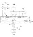
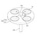
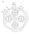
이하에서는, 도 1 내지 도 8을 참조하여 본 발명의 실시예들에 따른 원자층 증착장치(100)에 대해 상세히 설명한다. 참고적으로, 도 1은 본 발명의 일 실시예에 따른 원자층 증착장치(100)의 종단면도이고, 도 2는 도 1의 원자층 증착장치(100)에서 서셉터(102)의 일 예를 설명하기 위한 사시도이다. 또한, 도 3은 도 1의 원자층 증착장치(100)에서 가스분사 유닛(103)의 일 예를 설명하기 위한 평면 도이다. 또한, 도 4와 도 5는 도 3의 가스분사 유닛(103)의 일 예의 구조와 동작을 설명하기 위한 요부 사시도들이고, 도 6과 도 7은 도 4와 도 5의 가스분사 유닛(103)의 변형 실시예의 구조와 동작을 설명하기 위한 단면도들이다. 그리고 도 8은 도 1의 원자층 증착장치(100)에서 플라즈마 발생부(122, 132)의 일 예를 설명하기 위한 요부 사시도이다.Hereinafter, an atomic layer deposition apparatus 100 according to embodiments of the present invention will be described in detail with reference to FIGS. 1 to 8. For reference, FIG. 1 is a longitudinal cross-sectional view of an atomic layer deposition apparatus 100 according to an embodiment of the present invention, and FIG. 2 illustrates an example of the
도 1을 참조하면, 원자층 증착장치(100)는 프로세스 챔버(101), 서셉터(102), 가스분사 유닛(103) 및 플라즈마 발생부(122, 132)를 포함하여 이루어진다. 본 발명에 따르면, 상기 서셉터(102)와 상기 가스분사 유닛(103)은 서로에 대해 고정 형성되고, 상기 플라즈마 발생부(122, 132)는 상기 각 기판(10) 상부에 플라즈마를 발생시키도록 형성된다.Referring to FIG. 1, the atomic layer deposition apparatus 100 includes a
상기 프로세스 챔버(101)는 다수의 기판(10)을 수용하여 상기 기판(10) 표면에 소정의 박막을 증착하는 공간을 제공한다. 여기서, 상기 원자층 증착장치(100)는 진공에 가까운 저압 분위기에서 증착 공정이 수행되므로 상기 프로세스 챔버(101)는 진공을 유지할 수 있는 밀폐 구조를 갖는다.The
이하에서는 4 장의 기판(10)이 수용되어 증착 공정이 수행되는 원자층 증착장치(100)를 예로 들어 설명한다. 그러나 상기 원자층 증착장치(100)에 동시에 수용되는 기판(10)의 수는 도면에 의해 한정되는 것은 아니며 실질적으로 다양하게 변경될 수 있다.Hereinafter, an atomic layer deposition apparatus 100 in which four
상기 기판(10)은 실리콘 웨이퍼(silicon wafer)일 수 있다. 그러나 본 발명의 대상이 실리콘 웨이퍼에 한정되는 것은 아니며, 상기 기판(10)은 LCD(liquid crystal display), PDP(plasma display panel)와 같은 평판 디스플레이 장치용으로 사용하는 유리를 포함하는 투명 기판일 수 있다. 또한, 상기 기판(10)은 형상 및 크기가 도면에 의해 한정되는 것은 아니며, 원형 및 사각형 등 실질적으로 다양한 형상과 크기를 가질 수 있다.The
상기 서셉터(102)는 상기 프로세스 챔버(101) 내에 구비되어 상기 다수의 기판(10)이 수평 방향으로 안착된다.The
상기 가스분사 유닛(103)은 상기 서셉터(102)에 안착된 상기 기판(10) 표면으로 증착가스를 제공한다.The
여기서, 증착가스는 박막을 증착하는 공정에서 사용되는 가스들을 말하는 것으로, 상기 기판(10)에 증착시키고자 하는 박막을 구성하는 소스 물질을 포함하는 한 종류 이상의 가스와 상기 가스의 퍼지를 위한 가스를 포함한다. 본 실시예에서는 박막을 구성하는 소스 물질을 포함하고 상기 기판(10)에 물리적으로 흡착되는 제1 소스가스(S1)와 상기 제1 소스가스(S1)와 화학적으로 반응하여 박막을 형성하는 제2 소스가스(S2) 및 상기 기판(10), 상기 제1 소스가스(S1), 상기 제2 소스가스(S2) 및 증착된 박막과 화학적으로 반응하지 않는 안정한 퍼지가스(PG)가 사용된다. 예를 들어, 실리콘 박막을 증착하기 위해서 상기 제1 소스가스(S1)는 실리콘을 포함하는 실란(Silane, SiH4) 또는 디실란(Disilane, Si2H6), 4불화 실리콘(SiF4) 중 어느 하나의 가스를 사용하고, 상기 제2 소스가스(S2)는 산소(O2)나 오존(O3) 가스를 사용할 수 있다. 그리고 상기 퍼지가스(PG)는 아르곤(Ar)이나 질소(N2), 헬륨(He) 중 어느 하나의 가스 또는 둘 이상 혼합된 가스를 사용할 수 있 다. 그러나 본 발명이 이에 한정되는 것은 아니며 증착가스의 수와 종류는 실질적으로 다양하게 변경될 수 있다.Here, the deposition gas refers to gases used in the process of depositing a thin film, and at least one gas containing a source material constituting the thin film to be deposited on the
여기서, 상기 가스분사 유닛(103)은 상기 제1 및 제2 소스가스(S1, S2)를 제공하는 소스가스 분사부(131)와 상기 퍼지가스(PG)를 제공하는 퍼지가스 분사부(133)로 이루어진다.The
상기 소스가스 분사부(131)는 상기 프로세스 챔버(101) 상부에서 상기 서셉터(102) 상부에 구비되어 상기 기판(10)으로 상기 제1 및 제2 소스가스(S1, S2)를 분사하도록 형성된다. 그리고 상기 퍼지가스 분사부(133)는 상기 서셉터(102)에 구비되어 상기 퍼지가스(PG)를 분사하도록 형성된다.The
상기 가스분사 유닛(103)에는 상기 가스분사 유닛(103)으로 증착가스를 공급하는 가스 공급부가 구비된다. 예를 들어, 상기 가스 공급부는 상기 제1 소스가스(S1)를 공급하는 제1 공급원(141)과 상기 제2 소스가스(S2)를 공급하는 제2 공급원(142), 그리고, 상기 퍼지가스(PG)를 공급하는 제3 공급원(143)으로 이루어진다. 그리고 상기 제1 및 제2 공급원(141, 142)은 상기 소스가스 분사부(131)에 연결되고, 상기 제3 공급원(143)은 상기 퍼지가스 분사부(133)에 연결된다.The
한편, 도 1에는 하나의 소스가스 분사부(131)에만 상기 제1 및 제2 공급원(141, 142)이 연결된 것으로 도시하였으나, 모든 소스가스 분사부(131)에 상기 제1 및 제2 공급원(141, 142)이 연결되어 있음은 쉽게 이해 가능할 것이다.In FIG. 1, the first and
한편, 본 발명에 따르면 상기 서셉터(102) 및 상기 가스분사 유닛(103)은 서로에 대해 고정되게 형성되고, 상기 가스분사 유닛(103)은 상기 기판(10)에 일대일 대응되는 다수의 소스가스 분사부(131)와 상기 서셉터(102) 중앙의 하나의 퍼지가스 분사부(133)로 이루어진다.Meanwhile, according to the present invention, the
상기 서셉터(102)와 상기 가스분사 유닛(103)에는 상기 기판(10)에 플라즈마를 발생시키는 플라즈마 발생부(122, 132)가 구비된다. 여기서, 원자층 증착 공정을 위해 유지되는 상기 프로세스 챔버(101) 내부의 압력 조건에서 플라즈마를 발생시킬 수 있도록, 상기 플라즈마 발생부(122, 132)는 정전결합성 플라즈마(capacitively coupled plasma, CCP)를 발생시키게 된다.The
즉, 상기 플라즈마 발생부(122, 132)는 상기 기판(10)을 사이에 두고 상기 소스가스 분사부(131)에 구비된 제1 전극(132)과 상기 서셉터(102)에 구비되어 상기 기판(10)이 안착된 제2 전극(122)으로 이루어진다. 그리고 상기 제1 전극(132)과 상기 제2 전극(122) 사이의 전압차에 따른 전기장에 의해 상기 증착가스가 플라즈마 상태가 된다.That is, the
또한, 상기 플라즈마 발생부(122, 132)는 상기 제1 및 제2 전극(132, 122)에 고주파 전원을 인가하는 전원 공급부(151, 152)가 구비되며, 특히, 상기 전원 공급부(151, 152)는 상기 제1 및 제2 전극(132, 122)에 서로 다른 주파수 대의 고주파 전원을 인가하는 이중 주파수(dual frequency) 방식으로 플라즈마를 발생시키게 된다. 예를 들어, 상기 전원 공급부(151, 152)는 상기 제1 및 제2 전극(132, 122) 중 하나에는 27.12 ㎒의 고주파 전원이 인가되고, 다른 하나의 전극에는 13.56 ㎒의 고주파 전원이 인가된다.In addition, the
여기서, 상기 프로세스 챔버(101)의 중앙 상부에는 상기 프로세스 챔버(101) 내부의 배기가스를 흡입하여 배출시키는 배기부(135)가 구비된다. 예를 들어, 상기 배기부(135)는 상기 소스가스 분사부(131)가 형성된 상기 프로세스 챔버(101) 상면에 구비되며, 특히, 상기 다수의 기판(10)에서 균일하게 배기가스를 배출시킬 수 있도록 상기 프로세스 챔버(101)의 중앙 상부에 구비된다. 예를 들어, 상기 배기부(135)는 다수의 배기홀(351)과 상기 배기홀(351)에서 흡입된 배기가스의 유로가 되는 배기 버퍼(352, 도 6, 도 7 참조)로 이루어지고, 상기 배기 버퍼(352)의 일측에는 상기 배기 버퍼(352) 내부의 배기가스를 배출시키는 배기 펌프(136)이 구비된다.Here, an
도 2를 참조하면, 상기 서셉터(102)는 상기 기판(10)이 수평으로 안착될 수 있도록 평편한 상면을 갖고 소정 직경을 갖는 원형 플레이트 형상을 갖는 지지 블록(121)과 상기 지지 블록(121) 하부에 구비되어 상기 지지 블록(121)을 지지하는 구동축(125)으로 이루어진다. 또한, 상기 4 장의 기판(10)이 상기 서셉터(102)의 원주 방향을 따라 90° 간격으로 안착된다.Referring to FIG. 2, the
여기서, 상기 서셉터(102)의 형상이 도면에 의해 한정되는 것은 아니며 실질적으로 다양한 형태를 가질 수 있다. 또한, 도면에서는 상기 서셉터(102)는 하나의 지지 블록(121)으로 이루어지고 상기 4 장의 기판(10)이 하나의 지지 블록(121)에 안착된 예를 설명하였으나, 상기 서셉터(102)는 상기 한 장의 기판(10)이 각각 안착되는 다수의 서셉터(102)가 구비되는 것도 가능하다.Here, the shape of the
상기 서셉터(102) 중앙에는 상기 기판(10)으로 퍼지가스(PG)를 분사하기 위한 퍼지가스 분사부(133)가 구비된다.In the center of the
상기 퍼지가스 분사부(133)는 상기 서셉터(102) 중앙에서 구비되어 상기 서셉터(102)의 원주 방향을 향해 상기 퍼지가스(PG)를 제공하도록 형성된다. 예를 들어, 상기 퍼지가스 분사부(133)는 상기 방사상으로 배치된 기판(10)으로 상기 퍼지가스(PG)를 제공하도록 원형 단면을 갖고 내부에 상기 퍼지가스(PG)의 유로가 형성된 중공형 기둥 형태를 가지며 상기 퍼지가스 분사부(133)의 외주면 상에 조밀하게 퍼지가스 퍼지홀(331)이 형성된다. 또한, 상기 퍼지가스 분사부(133)는 상기 서셉터(102) 표면에서 소정 높이를 갖는 원통 형태를 갖는다.The purge
그리고 상기 구동축(125)을 통해 상기 제3 공급원(143)에서 상기 퍼지가스 분사부(133)로 상기 퍼지가스(PG)가 공급된다.The purge gas PG is supplied from the
그러나 상기 퍼지가스 분사부(133)의 형태는 도면에 한정되는 것은 아니며, 상기 퍼지가스 분사부(133)는 단면이 다각형을 포함하여 실질적으로 다양한 형태를 가질 수 있다. 예를 들어, 상기 퍼지가스 분사부(133)는 상기 기판(10)을 마주보는 부분이 평면이 되도록 정육각형 단면을 갖는 기둥 형태를 가질 수 있다. 또한, 상기 퍼지홀(331)의 크기나 개수 및 배치 형태는 도면에 의해 한정되는 것은 아니며, 실질적으로 다양한 형태로 배치될 수 있으며 원형이나 다각형 홀 또는 슬릿 형태를 가질 수 있다.However, the shape of the
한편, 본 실시예에서는 상기 퍼지가스 분사부(133)가 다수의 홀이 표면에 조밀하게 형성된 샤워헤드(showerhead) 형태를 갖는 예를 설명하였으나, 본 발명이 도면에 의해 한정되는 것은 아니며, 상기 퍼지가스 분사부(133)는 노즐이나 에어 나이프(air knife) 형태를 가질 수 있다.On the other hand, in the present embodiment has been described an example in which the purge
도 3을 참조하면, 상기 소스가스 분사부(131)는 상기 기판(10)과 일대일 대응되어 상기 기판(10)으로 각각 상기 제1 및 제2 소스가스(S1, S2)를 분사하도록 게 다수의 소스가스 분사부(131)가 구비된다.Referring to FIG. 3, the
도 4 내지 도 5를 참조하면, 상기 소스가스 분사부(131)는 상기 제1 소스가스(S1)의 유로(이하, 제1 유로(341)라 한다)가 형성된 제1 분사체(311)와 상기 제2 소스가스(S2)의 유로(이하, 제2 유로(342)라 한다)가 형성된 제2 분사체(312)로 이루어진다. 그리고 상기 제1 유로(341)에는 상기 제1 공급원(141)이 연결되어 상기 제1 소스가스(S1)가 분사되고, 상기 제2 유로(342)에는 상기 제2 공급원(142)이 연결되어 상기 제2 소스가스(S2)가 분사된다.4 to 5, the
특히, 상기 제2 분사체(312)는 상기 제1 유로(341) 내에 구비되어 승강 이동에 의해 상기 제1 유로(341)를 선택적으로 개폐하게 된다.In particular, the
상세하게는, 상기 제1 분사체(311)의 내측면과 상기 제2 분사체(312)의 외측면 사이의 간극이 상기 제1 유로(341)가 되고, 상기 제2 분사체(312)의 이동에 의해 상기 제2 분사체(312)가 상기 제1 분사체(311) 내측면에 밀착되면서 상기 제1 유로(341)가 폐쇄된다. 예를 들어, 상기 제2 분사체(312)는 상기 기판(10)을 향해 단면적이 점차 증가되는 종형 또는 깔대기 형태를 가질 수 있다. 그리고 상기 제2 유로(342)는 상기 제2 분사체(312)를 관통하여 상기 제2 분사체(312)의 하면에서 상기 제2 소스가스(S2)가 분사되도록 형성되고, 상기 제2 분사체(312)의 상부에서 상기 제2 공급원(142)이 연결된다.In detail, the gap between the inner surface of the
상기 제2 분사체(312)는 상기 제1 유로(341) 내부에서 상하로 이동 가능하게 형성되는데, 상기 제2 분사체(312)의 상부를 통해 상기 제1 유로(341) 내부의 상기 제1 소스가스(S1)가 외부로 유출되는 것을 방지하기 위한 실링부(315)가 구비된다. 여기서, 상기 실링부(315)는 상기 제2 분사체(312)의 이동에 의해 신축 가능한 재질로 형성되는 것이 바람직하다. 예를 들어, 상기 실링부(315)는 상기 제1 유로(341)의 일측과 상기 제2 분사체(312)의 상부 일측에 연결되어 상기 제1 유로(341)를 밀폐시키고 신축 가능한 가스켓(gasket)일 수 있다.The
상기 소스가스 분사부(131)의 동작을 간단하게 설명하면 다음과 같다.The operation of the source
도 4에 도시한 바와 같이, 상기 제2 분사체(312)가 하부로 이동하면 상기 제1 분사체(311)와 상기 제2 분사체(312) 사이에 소정의 간극, 즉, 상기 제1 유로(341)가 개방되면서 상기 제1 유로(341)를 통해 상기 제1 소스가스(S1)가 분사된다.As shown in FIG. 4, when the
그리고 도 5에 도시한 바와 같이, 상기 제2 분사체(312)가 상부로 이동하여 상기 제1 및 제2 분사체(311, 312)가 밀착되면 상기 제1 유로가 폐쇄되어 상기 제1 소스가스(S1)의 분사가 중단된다.As shown in FIG. 5, when the
여기서, 상기 제1 소스가스(S1)는 상기 제2 분사체(312)의 승강 이동에 의해 단속적으로 분사되는 데 반해, 상기 제2 소스가스(S2)는 지속적으로 분사된다.Here, the first source gas S1 is intermittently injected by the lifting movement of the
한편, 상술한 실시예와는 달리 상기 제1 소스가스(S1)와 상기 제2 소스가스(S2)가 교번적으로 분사되도록 상기 제2 소스가스(S2)를 단속적으로 분사할 수 있다.Meanwhile, unlike the above-described embodiment, the second source gas S2 may be intermittently injected such that the first source gas S1 and the second source gas S2 are alternately injected.
예를 들어, 도 6과 도 7에 도시한 바와 같이, 상기 제2 공급원(142)이 상기 제2 분사체(312)에 연결되어 상기 제2 소스가스(S2)를 공급하는 유로 상에는 상기 제2 소스가스(S2)의 공급을 선택적으로 단속시키기 위한 밸브부(345)가 구비된다. 그리고, 상기 제1 소스가스(S1)의 공급과 교번적으로 상기 제2 소스가스(S2)가 공급될 수 있도록 상기 제2 소스가스(S2)의 공급은 단속적으로 개폐하게 된다.For example, as illustrated in FIGS. 6 and 7, the
또한, 상기 제1 소스가스(S1)는 상기 제1 유로(341)가 폐쇄된 동안에는 상기 제1 소스가스(S1)의 공급을 중단시키거나 상기 제1 소스가스(S1)를 다른 곳으로 유동시킬 필요가 있다. 예를 들어, 상기 제1 공급원(141)이 상기 제1 유로(341)에 연결되어 상기 제1 소스가스(S1)를 공급하는 유로 상에 개폐를 위한 소정의 밸브(미도시)를 구비하여, 상기 제1 유로(341)가 폐쇄되었을 때는 상기 제1 소스가스(S1)의 공급을 중단할 수 있다. 그러나, 증착 공정에서 소스가스는 매우 짧은 주기로 수천 번 단속되는데 밸브를 통해 이러한 소스가스의 단속을 제어하기는 어려울 수 있으며 정밀하게 제어하기 어려운 문제점이 있다.In addition, the first source gas S1 stops the supply of the first source gas S1 or flows the first source gas S1 to another place while the
이러한 제1 소스가스(S1)의 단속 제어를 위해 본 실시예에서는, 도 6과 도 7에 도시한 바와 같이, 상기 배기부(135)와 상기 제1 유로(341)를 연통시키는 제3 유로(343)와 소스 배기홀(353)을 형성하고, 상기 제3 유로(343) 상에 상기 제3 유로(343)를 개폐하는 개폐부(346)가 구비될 수 있다.In this embodiment, for controlling the interruption of the first source gas S1, as illustrated in FIGS. 6 and 7, a third flow path (not shown) in which the
여기서, 상기 개폐부(346)는 상기 제2 분사체(312)와 동시에 상하로 승강 이동 가능하도록 형성된다. 도면에서 미설명 도면부호 '347'은 상기 제2 분사체(312)와 상기 개폐부(346)를 동시에 승강 이동시키기 위한 구동부(347)이다.Here, the opening and
즉, 도 6에 도시한 바와 같이, 상기 제2 분사체(312)가 하부로 이동하여 상 기 제1 유로(341)가 개방되면 상기 개폐부(346) 역시 하부로 이동함에 따라 상기 제3 유로(343)가 폐쇄된다. 그리고 상기 제1 유로(341)로 공급되는 상기 제1 소스가스(S1)는 상기 제1 유로(341)를 통해 상기 기판(10)으로 분사된다. 여기서, 상기 제2 분사체(312)가 하부로 이동하면 상기 밸브부(345)가 폐쇄되어 상기 제2 소스가스(S2)의 분사를 중단시킨다.That is, as shown in FIG. 6, when the
그리고, 도 7에 도시한 바와 같이, 상기 제2 분사체(312)가 상부로 이동하여 상기 제1 유로(341)가 폐쇄되면 상기 개폐부(346) 역시 상부로 이동함에 따라 상기 제3 유로(343)가 개방되면서, 상기 제1 유로(341)로 공급되는 상기 제1 소스가스(S1)는 상기 제3 유로(343)를 통해 상기 배기 버퍼(352)로 유입되어 배출된다. 여기서, 상기 제2 분사체(312)가 상부로 이동하면 상기 밸브부(345)가 개방되어 상기 제2 유로(342)를 통해 상기 제2 소스가스(S2)가 분사된다.As shown in FIG. 7, when the
그러나 상기 개폐부(346)의 형태와 위치가 도면에 의해 한정되는 것은 아니며 상기 제3 유로(343)를 개폐할 수 있는 실질적으로 다양한 형상을 가질 수 있다.However, the shape and position of the opening and
한편, 도 8을 참조하면, 상기 플라즈마 발생부(122, 132)는 상기 프로세스 챔버(101) 내부에 구비되어 상기 기판(10) 상부에 플라즈마를 발생시킴으로써 상기 증착가스의 반응성을 향상시키고 증착 속도와 막질을 향상시킬 수 있다.Meanwhile, referring to FIG. 8, the
상기 플라즈마 발생부(122, 132)는 상기 기판(10)에 용량결합성 플라즈마를 발생시키도록 서로 평행한 한 쌍의 평판형 전극인 제1 전극(132)과 제2 전극(122)으로 이루어지고, 이중 주파수 방식으로 플라즈마를 발생시킬 수 있도록 상기 제1 전극(132) 및 상기 제2 전극(122)에 고주파 전원을 인가하는 전원 공급부(151, 152)로 이루어진다.The
상기 제1 전극(132)은 상기 소스가스 분사부(131)에 구비되고, 상기 제2 전극(122)은 상기 제1 전극(132)과 대향되도록 상기 서셉터(102)에 구비된다. 특히, 상기 플라즈마 발생부(122, 132)는 상기 기판(10)에 개별적으로 각각 플라즈마를 발생시키도록 형성된다. 즉, 상기 제1 및 제2 전극(132, 122)은 상기 기판(10)과 일대일 대응되게 다수 개가 구비되며, 상기 제1 전극(132)은 상기 각 소스가스 분사부(131)에 구비되고, 상기 제2 전극(122)은 상기 기판(10)이 각각 안착된다.The
상기 플라즈마 발생부(122, 132)는 상기 제1 전극(132)에 소정 주파수대의 고주파 전원이 인가되고, 상기 제2 전극(122)에 다른 주파수대의 고주파 전원이 인가되면, 상기 제1 및 제2 전극(132, 122) 사이의 전압차에 의해 소정의 전기장이 형성되고 이와 같은 전기장에 의해 상기 기판(10) 상부에는 플라즈마(P)가 형성된다. 예를 들어, 상기 제1 및 제2 전극(132, 122) 중 하나의 전극에는 27.12 ㎒의 고주파 전원이 인가되고, 다른 하나의 전극에는 13.56 ㎒의 고주파 전원이 인가된다.When the high frequency power of a predetermined frequency band is applied to the
상술한 바와 같이, 본 발명의 바람직한 실시예를 참조하여 설명하였지만 해당 기술분야의 숙련된 당업자라면 하기의 청구범위에 기재된 본 발명의 사상 및 영역으로부터 벗어나지 않는 범위 내에서 본 발명을 다양하게 수정 및 변경시킬 수 있음을 이해할 수 있을 것이다.As described above, although described with reference to the preferred embodiment of the present invention, those skilled in the art various modifications and variations of the present invention without departing from the spirit and scope of the invention described in the claims below I can understand that you can.
도 1은 본 발명의 일 실시예에 따른 원자층 증착장치의 종단면도;1 is a longitudinal sectional view of an atomic layer deposition apparatus according to an embodiment of the present invention;
도 2는 도 1의 원자층 증착장치에서 서셉터의 일 예를 설명하기 위한 사시도;2 is a perspective view illustrating an example of a susceptor in the atomic layer deposition apparatus of FIG. 1;
도 3은 도 1의 원자층 증착장치에서 소스가스 분사부의 일 예를 설명하기 위한 평면도;3 is a plan view for explaining an example of the source gas injection unit in the atomic layer deposition apparatus of FIG.
도 4와 도 5는 도 3의 소스가스 분사부의 구조 및 동작을 설명하기 위한 요부 사시도들;4 and 5 are main perspective views for explaining the structure and operation of the source gas injection unit of FIG.
도 6과 도 7은 도 4와 도 5의 변형 실시예에 따른 소스가스 분사부의 구조 및 동작을 설명하기 위한 단면도들;6 and 7 are cross-sectional views illustrating the structure and operation of the source gas injection unit according to the modified embodiment of FIGS. 4 and 5;
도 8은 도 1의 원자층 증착장치에서 플라즈마 발생부의 일 예를 설명하기 위한 요부 사시도이다.8 is a perspective view illustrating main parts of an example of the plasma generation unit in the atomic layer deposition apparatus of FIG. 1.
<도면의 주요 부분에 대한 부호의 설명><Description of the symbols for the main parts of the drawings>
10: 기판100: 원자층 증착장치10: substrate 100: atomic layer deposition apparatus
101: 프로세스 챔버102: 서셉터101: process chamber 102: susceptor
103: 가스분사 유닛104: 가스 공급부103: gas injection unit 104: gas supply unit
121: 지지 블록122: 제2 전극121: support block 122: second electrode
125: 구동축131: 소스가스 분사부125: drive shaft 131: source gas injection portion
132: 제1 전극133: 퍼지가스 분사부132: first electrode 133: purge gas injection unit
135: 배기부136: 배기 펌프135: exhaust part 136: exhaust pump
141: 제1 공급원142: 제2 공급원141: first source 142: second source
143: 제3 공급원151, 152: 전원 공급부143:
311, 312: 분사체315: 실링부311 and 312: Injector 315: Sealing part
331: 퍼지홀341: 제1 유로331: purge hole 341: first flow path
342: 제2 유로343: 제3 유로342: Second euro 343: Third euro
345: 밸브부346: 개폐부345: valve portion 346: opening and closing portion
347: 구동부351: 배기홀347: drive unit 351: exhaust hole
352: 배기 버퍼353: 소스 배기홀352: exhaust buffer 353: source exhaust hole
P: 플라즈마PG: 퍼지가스P: plasma PG: purge gas
S1, S2: 소스가스S1, S2: Source Gas
Claims (15)
Translated fromKoreanPriority Applications (1)
| Application Number | Priority Date | Filing Date | Title |
|---|---|---|---|
| KR1020080135372AKR101028408B1 (en) | 2008-12-29 | 2008-12-29 | Gas injection unit and atomic layer deposition apparatus having the same |
Applications Claiming Priority (1)
| Application Number | Priority Date | Filing Date | Title |
|---|---|---|---|
| KR1020080135372AKR101028408B1 (en) | 2008-12-29 | 2008-12-29 | Gas injection unit and atomic layer deposition apparatus having the same |
Publications (2)
| Publication Number | Publication Date |
|---|---|
| KR20100077440A KR20100077440A (en) | 2010-07-08 |
| KR101028408B1true KR101028408B1 (en) | 2011-04-13 |
Family
ID=42638791
Family Applications (1)
| Application Number | Title | Priority Date | Filing Date |
|---|---|---|---|
| KR1020080135372AActiveKR101028408B1 (en) | 2008-12-29 | 2008-12-29 | Gas injection unit and atomic layer deposition apparatus having the same |
Country Status (1)
| Country | Link |
|---|---|
| KR (1) | KR101028408B1 (en) |
Cited By (10)
| Publication number | Priority date | Publication date | Assignee | Title |
|---|---|---|---|---|
| KR101445224B1 (en)* | 2012-09-18 | 2014-09-29 | 피에스케이 주식회사 | Apparatus and method for treating substrate |
| US8955547B2 (en) | 2011-10-19 | 2015-02-17 | Applied Materials, Inc. | Apparatus and method for providing uniform flow of gas |
| US9109754B2 (en) | 2011-10-19 | 2015-08-18 | Applied Materials, Inc. | Apparatus and method for providing uniform flow of gas |
| US9353440B2 (en) | 2013-12-20 | 2016-05-31 | Applied Materials, Inc. | Dual-direction chemical delivery system for ALD/CVD chambers |
| US9464353B2 (en) | 2013-11-21 | 2016-10-11 | Wonik Ips Co., Ltd. | Substrate processing apparatus |
| US9514933B2 (en) | 2014-01-05 | 2016-12-06 | Applied Materials, Inc. | Film deposition using spatial atomic layer deposition or pulsed chemical vapor deposition |
| US9631277B2 (en) | 2011-03-01 | 2017-04-25 | Applied Materials, Inc. | Atomic layer deposition carousel with continuous rotation and methods of use |
| US9748125B2 (en) | 2012-01-31 | 2017-08-29 | Applied Materials, Inc. | Continuous substrate processing system |
| US9831109B2 (en) | 2013-03-11 | 2017-11-28 | Applied Materials, Inc. | High temperature process chamber lid |
| KR20190077931A (en)* | 2017-12-26 | 2019-07-04 | 주성엔지니어링(주) | Apparatus for Processing Substrate |
Families Citing this family (12)
| Publication number | Priority date | Publication date | Assignee | Title |
|---|---|---|---|---|
| KR101219061B1 (en)* | 2010-11-30 | 2013-01-21 | 주식회사 케이씨텍 | Gas distribution module for narrow interval of spin nozzle unit and upright type deposition apparatus having the gas distribution module |
| KR101243878B1 (en)* | 2011-06-09 | 2013-03-20 | 주성엔지니어링(주) | An apparatus for manufacturing a solar cell |
| KR101830976B1 (en) | 2011-06-30 | 2018-02-22 | 삼성디스플레이 주식회사 | Apparatus for atomic layer deposition |
| KR101869948B1 (en)* | 2011-12-26 | 2018-06-22 | 주식회사 원익아이피에스 | Gas injecting device and Substrate processing apparatus having the same |
| WO2013147377A1 (en)* | 2012-03-30 | 2013-10-03 | 주식회사 테스 | Vapor deposition apparatus |
| KR101332564B1 (en)* | 2012-03-30 | 2013-12-02 | 주식회사 테스 | Vapor deposition apparatus |
| KR101990195B1 (en)* | 2016-06-28 | 2019-06-18 | (주)아이씨디 | Linear Nozzle for High-Density Thin Film Deposition |
| US10403474B2 (en)* | 2016-07-11 | 2019-09-03 | Lam Research Corporation | Collar, conical showerheads and/or top plates for reducing recirculation in a substrate processing system |
| KR102179754B1 (en)* | 2016-12-23 | 2020-11-17 | 주식회사 원익아이피에스 | Substrate processing ALD |
| KR102184005B1 (en)* | 2016-12-23 | 2020-11-30 | 주식회사 원익아이피에스 | Method of processing ALD |
| JP6981356B2 (en)* | 2018-04-24 | 2021-12-15 | 東京エレクトロン株式会社 | Film forming equipment and film forming method |
| CN112670150B (en)* | 2020-12-22 | 2023-11-17 | 马鞍山市胜康精密机电有限公司 | Ion implantation device for processing photoelectric components |
Citations (2)
| Publication number | Priority date | Publication date | Assignee | Title |
|---|---|---|---|---|
| KR20040079556A (en)* | 2003-03-07 | 2004-09-16 | 삼성전자주식회사 | High density plasma apparatus for thin film deposition |
| KR20060131119A (en)* | 2005-06-15 | 2006-12-20 | 주성엔지니어링(주) | Thin film manufacturing apparatus and thin film deposition method using the same |
- 2008
- 2008-12-29KRKR1020080135372Apatent/KR101028408B1/enactiveActive
Patent Citations (2)
| Publication number | Priority date | Publication date | Assignee | Title |
|---|---|---|---|---|
| KR20040079556A (en)* | 2003-03-07 | 2004-09-16 | 삼성전자주식회사 | High density plasma apparatus for thin film deposition |
| KR20060131119A (en)* | 2005-06-15 | 2006-12-20 | 주성엔지니어링(주) | Thin film manufacturing apparatus and thin film deposition method using the same |
Cited By (17)
| Publication number | Priority date | Publication date | Assignee | Title |
|---|---|---|---|---|
| US9631277B2 (en) | 2011-03-01 | 2017-04-25 | Applied Materials, Inc. | Atomic layer deposition carousel with continuous rotation and methods of use |
| USRE47440E1 (en) | 2011-10-19 | 2019-06-18 | Applied Materials, Inc. | Apparatus and method for providing uniform flow of gas |
| US8955547B2 (en) | 2011-10-19 | 2015-02-17 | Applied Materials, Inc. | Apparatus and method for providing uniform flow of gas |
| US9109754B2 (en) | 2011-10-19 | 2015-08-18 | Applied Materials, Inc. | Apparatus and method for providing uniform flow of gas |
| USRE48994E1 (en) | 2011-10-19 | 2022-03-29 | Applied Materials, Inc. | Apparatus and method for providing uniform flow of gas |
| US9748125B2 (en) | 2012-01-31 | 2017-08-29 | Applied Materials, Inc. | Continuous substrate processing system |
| US10236198B2 (en) | 2012-01-31 | 2019-03-19 | Applied Materials, Inc. | Methods for the continuous processing of substrates |
| KR101445224B1 (en)* | 2012-09-18 | 2014-09-29 | 피에스케이 주식회사 | Apparatus and method for treating substrate |
| US10879090B2 (en) | 2013-03-11 | 2020-12-29 | Applied Materials, Inc. | High temperature process chamber lid |
| US9831109B2 (en) | 2013-03-11 | 2017-11-28 | Applied Materials, Inc. | High temperature process chamber lid |
| US9464353B2 (en) | 2013-11-21 | 2016-10-11 | Wonik Ips Co., Ltd. | Substrate processing apparatus |
| US9765432B2 (en) | 2013-12-20 | 2017-09-19 | Applied Materials, Inc. | Dual-direction chemical delivery system for ALD/CVD chambers |
| US10400335B2 (en) | 2013-12-20 | 2019-09-03 | Applied Materials, Inc. | Dual-direction chemical delivery system for ALD/CVD chambers |
| US9353440B2 (en) | 2013-12-20 | 2016-05-31 | Applied Materials, Inc. | Dual-direction chemical delivery system for ALD/CVD chambers |
| US9514933B2 (en) | 2014-01-05 | 2016-12-06 | Applied Materials, Inc. | Film deposition using spatial atomic layer deposition or pulsed chemical vapor deposition |
| KR20190077931A (en)* | 2017-12-26 | 2019-07-04 | 주성엔지니어링(주) | Apparatus for Processing Substrate |
| KR102401746B1 (en) | 2017-12-26 | 2022-05-30 | 주성엔지니어링(주) | Apparatus for Processing Substrate |
Also Published As
| Publication number | Publication date |
|---|---|
| KR20100077440A (en) | 2010-07-08 |
Similar Documents
| Publication | Publication Date | Title |
|---|---|---|
| KR101028408B1 (en) | Gas injection unit and atomic layer deposition apparatus having the same | |
| KR101134277B1 (en) | Atomic layer deposition apparatus | |
| KR101021372B1 (en) | Atomic layer deposition apparatus | |
| KR20130067600A (en) | Atomic layer deposition apparatus providing direct palsma | |
| KR20100077442A (en) | Showerhead and atomic layer deposition apparatus having the same | |
| KR101046613B1 (en) | Atomic layer deposition apparatus | |
| KR20100077828A (en) | Atomic layer deposition apparatus | |
| KR20080105617A (en) | Chemical Vapor Deposition and Plasma Enhanced Chemical Vapor Deposition | |
| KR101473334B1 (en) | Atomic layer deposition apparatus | |
| KR20100077889A (en) | Atomic layer deposition apparatus | |
| KR101046611B1 (en) | Batch Type Atomic Layer Deposition System | |
| KR101028407B1 (en) | Atomic layer deposition apparatus | |
| KR101126389B1 (en) | Susceptor unit for atomic layer deposition apparatus | |
| KR20100002885A (en) | Atomic layer deposition apparatus | |
| KR20130085842A (en) | Substrate processing apparatus and substrate processing method | |
| KR101929481B1 (en) | Substrate processing apparatus and substrate processing method | |
| KR20110077743A (en) | Atomic layer deposition apparatus for deposition of multi-component thin films | |
| KR20120038675A (en) | Atomic layer deposition apparatus | |
| KR101027952B1 (en) | Shower head and atomic layer deposition apparatus having the same | |
| KR101027954B1 (en) | Shower head and atomic layer deposition apparatus having the same | |
| KR200457336Y1 (en) | Showerhead Unit for Atomic Layer Deposition Equipment | |
| KR20140041021A (en) | Deposition apparatus having cvd mode and ald mode | |
| KR102046391B1 (en) | Substrate processing apparatus and substrate processing method | |
| KR101111754B1 (en) | Batch type atomic layer deposition apparatus | |
| KR101675817B1 (en) | Deposition apparatus for semiconductor manufacturing |
Legal Events
| Date | Code | Title | Description |
|---|---|---|---|
| A201 | Request for examination | ||
| PA0109 | Patent application | Patent event code:PA01091R01D Comment text:Patent Application Patent event date:20081229 | |
| PA0201 | Request for examination | ||
| PG1501 | Laying open of application | ||
| E902 | Notification of reason for refusal | ||
| PE0902 | Notice of grounds for rejection | Comment text:Notification of reason for refusal Patent event date:20101109 Patent event code:PE09021S01D | |
| E701 | Decision to grant or registration of patent right | ||
| PE0701 | Decision of registration | Patent event code:PE07011S01D Comment text:Decision to Grant Registration Patent event date:20110331 | |
| GRNT | Written decision to grant | ||
| PR0701 | Registration of establishment | Comment text:Registration of Establishment Patent event date:20110404 Patent event code:PR07011E01D | |
| PR1002 | Payment of registration fee | Payment date:20110405 End annual number:3 Start annual number:1 | |
| PG1601 | Publication of registration | ||
| FPAY | Annual fee payment | Payment date:20140303 Year of fee payment:4 | |
| PR1001 | Payment of annual fee | Payment date:20140303 Start annual number:4 End annual number:4 | |
| FPAY | Annual fee payment | Payment date:20160404 Year of fee payment:6 | |
| PR1001 | Payment of annual fee | Payment date:20160404 Start annual number:6 End annual number:6 | |
| FPAY | Annual fee payment | Payment date:20170417 Year of fee payment:7 | |
| PR1001 | Payment of annual fee | Payment date:20170417 Start annual number:7 End annual number:7 | |
| FPAY | Annual fee payment | Payment date:20190328 Year of fee payment:9 | |
| PR1001 | Payment of annual fee | Payment date:20190328 Start annual number:9 End annual number:9 | |
| PR1001 | Payment of annual fee | Payment date:20200401 Start annual number:10 End annual number:10 | |
| PR1001 | Payment of annual fee | Payment date:20210401 Start annual number:11 End annual number:11 | |
| PR1001 | Payment of annual fee | Payment date:20240401 Start annual number:14 End annual number:14 |