KR101028291B1 - Switch unit control and method between the battery pack and the load, and a battery pack and battery management device comprising the device - Google Patents
Switch unit control and method between the battery pack and the load, and a battery pack and battery management device comprising the deviceDownload PDFInfo
- Publication number
- KR101028291B1 KR101028291B1KR1020090082215AKR20090082215AKR101028291B1KR 101028291 B1KR101028291 B1KR 101028291B1KR 1020090082215 AKR1020090082215 AKR 1020090082215AKR 20090082215 AKR20090082215 AKR 20090082215AKR 101028291 B1KR101028291 B1KR 101028291B1
- Authority
- KR
- South Korea
- Prior art keywords
- switch unit
- battery pack
- load
- switch
- turn
- Prior art date
- Legal status (The legal status is an assumption and is not a legal conclusion. Google has not performed a legal analysis and makes no representation as to the accuracy of the status listed.)
- Active
Links
Images


Classifications
- B—PERFORMING OPERATIONS; TRANSPORTING
- B60—VEHICLES IN GENERAL
- B60L—PROPULSION OF ELECTRICALLY-PROPELLED VEHICLES; SUPPLYING ELECTRIC POWER FOR AUXILIARY EQUIPMENT OF ELECTRICALLY-PROPELLED VEHICLES; ELECTRODYNAMIC BRAKE SYSTEMS FOR VEHICLES IN GENERAL; MAGNETIC SUSPENSION OR LEVITATION FOR VEHICLES; MONITORING OPERATING VARIABLES OF ELECTRICALLY-PROPELLED VEHICLES; ELECTRIC SAFETY DEVICES FOR ELECTRICALLY-PROPELLED VEHICLES
- B60L50/00—Electric propulsion with power supplied within the vehicle
- B60L50/50—Electric propulsion with power supplied within the vehicle using propulsion power supplied by batteries or fuel cells
- B60L50/52—Electric propulsion with power supplied within the vehicle using propulsion power supplied by batteries or fuel cells characterised by DC-motors
- B—PERFORMING OPERATIONS; TRANSPORTING
- B60—VEHICLES IN GENERAL
- B60L—PROPULSION OF ELECTRICALLY-PROPELLED VEHICLES; SUPPLYING ELECTRIC POWER FOR AUXILIARY EQUIPMENT OF ELECTRICALLY-PROPELLED VEHICLES; ELECTRODYNAMIC BRAKE SYSTEMS FOR VEHICLES IN GENERAL; MAGNETIC SUSPENSION OR LEVITATION FOR VEHICLES; MONITORING OPERATING VARIABLES OF ELECTRICALLY-PROPELLED VEHICLES; ELECTRIC SAFETY DEVICES FOR ELECTRICALLY-PROPELLED VEHICLES
- B60L50/00—Electric propulsion with power supplied within the vehicle
- B60L50/50—Electric propulsion with power supplied within the vehicle using propulsion power supplied by batteries or fuel cells
- B—PERFORMING OPERATIONS; TRANSPORTING
- B60—VEHICLES IN GENERAL
- B60K—ARRANGEMENT OR MOUNTING OF PROPULSION UNITS OR OF TRANSMISSIONS IN VEHICLES; ARRANGEMENT OR MOUNTING OF PLURAL DIVERSE PRIME-MOVERS IN VEHICLES; AUXILIARY DRIVES FOR VEHICLES; INSTRUMENTATION OR DASHBOARDS FOR VEHICLES; ARRANGEMENTS IN CONNECTION WITH COOLING, AIR INTAKE, GAS EXHAUST OR FUEL SUPPLY OF PROPULSION UNITS IN VEHICLES
- B60K6/00—Arrangement or mounting of plural diverse prime-movers for mutual or common propulsion, e.g. hybrid propulsion systems comprising electric motors and internal combustion engines
- B60K6/20—Arrangement or mounting of plural diverse prime-movers for mutual or common propulsion, e.g. hybrid propulsion systems comprising electric motors and internal combustion engines the prime-movers consisting of electric motors and internal combustion engines, e.g. HEVs
- B60K6/22—Arrangement or mounting of plural diverse prime-movers for mutual or common propulsion, e.g. hybrid propulsion systems comprising electric motors and internal combustion engines the prime-movers consisting of electric motors and internal combustion engines, e.g. HEVs characterised by apparatus, components or means specially adapted for HEVs
- B60K6/28—Arrangement or mounting of plural diverse prime-movers for mutual or common propulsion, e.g. hybrid propulsion systems comprising electric motors and internal combustion engines the prime-movers consisting of electric motors and internal combustion engines, e.g. HEVs characterised by apparatus, components or means specially adapted for HEVs characterised by the electric energy storing means, e.g. batteries or capacitors
- B—PERFORMING OPERATIONS; TRANSPORTING
- B60—VEHICLES IN GENERAL
- B60L—PROPULSION OF ELECTRICALLY-PROPELLED VEHICLES; SUPPLYING ELECTRIC POWER FOR AUXILIARY EQUIPMENT OF ELECTRICALLY-PROPELLED VEHICLES; ELECTRODYNAMIC BRAKE SYSTEMS FOR VEHICLES IN GENERAL; MAGNETIC SUSPENSION OR LEVITATION FOR VEHICLES; MONITORING OPERATING VARIABLES OF ELECTRICALLY-PROPELLED VEHICLES; ELECTRIC SAFETY DEVICES FOR ELECTRICALLY-PROPELLED VEHICLES
- B60L58/00—Methods or circuit arrangements for monitoring or controlling batteries or fuel cells, specially adapted for electric vehicles
- B60L58/10—Methods or circuit arrangements for monitoring or controlling batteries or fuel cells, specially adapted for electric vehicles for monitoring or controlling batteries
- B60L58/18—Methods or circuit arrangements for monitoring or controlling batteries or fuel cells, specially adapted for electric vehicles for monitoring or controlling batteries of two or more battery modules
- B60L58/21—Methods or circuit arrangements for monitoring or controlling batteries or fuel cells, specially adapted for electric vehicles for monitoring or controlling batteries of two or more battery modules having the same nominal voltage
- B—PERFORMING OPERATIONS; TRANSPORTING
- B60—VEHICLES IN GENERAL
- B60W—CONJOINT CONTROL OF VEHICLE SUB-UNITS OF DIFFERENT TYPE OR DIFFERENT FUNCTION; CONTROL SYSTEMS SPECIALLY ADAPTED FOR HYBRID VEHICLES; ROAD VEHICLE DRIVE CONTROL SYSTEMS FOR PURPOSES NOT RELATED TO THE CONTROL OF A PARTICULAR SUB-UNIT
- B60W10/00—Conjoint control of vehicle sub-units of different type or different function
- B60W10/24—Conjoint control of vehicle sub-units of different type or different function including control of energy storage means
- B60W10/26—Conjoint control of vehicle sub-units of different type or different function including control of energy storage means for electrical energy, e.g. batteries or capacitors
- H—ELECTRICITY
- H01—ELECTRIC ELEMENTS
- H01H—ELECTRIC SWITCHES; RELAYS; SELECTORS; EMERGENCY PROTECTIVE DEVICES
- H01H3/00—Mechanisms for operating contacts
- H01H3/001—Means for preventing or breaking contact-welding
- H—ELECTRICITY
- H01—ELECTRIC ELEMENTS
- H01H—ELECTRIC SWITCHES; RELAYS; SELECTORS; EMERGENCY PROTECTIVE DEVICES
- H01H33/00—High-tension or heavy-current switches with arc-extinguishing or arc-preventing means
- H01H33/02—Details
- H01H33/59—Circuit arrangements not adapted to a particular application of the switch and not otherwise provided for, e.g. for ensuring operation of the switch at a predetermined point in the AC cycle
- H—ELECTRICITY
- H02—GENERATION; CONVERSION OR DISTRIBUTION OF ELECTRIC POWER
- H02H—EMERGENCY PROTECTIVE CIRCUIT ARRANGEMENTS
- H02H9/00—Emergency protective circuit arrangements for limiting excess current or voltage without disconnection
- H02H9/001—Emergency protective circuit arrangements for limiting excess current or voltage without disconnection limiting speed of change of electric quantities, e.g. soft switching on or off
- H—ELECTRICITY
- H02—GENERATION; CONVERSION OR DISTRIBUTION OF ELECTRIC POWER
- H02J—CIRCUIT ARRANGEMENTS OR SYSTEMS FOR SUPPLYING OR DISTRIBUTING ELECTRIC POWER; SYSTEMS FOR STORING ELECTRIC ENERGY
- H02J7/00—Circuit arrangements for charging or depolarising batteries or for supplying loads from batteries
- H02J7/007—Regulation of charging or discharging current or voltage
- H02J7/00712—Regulation of charging or discharging current or voltage the cycle being controlled or terminated in response to electric parameters
- H02J7/00714—Regulation of charging or discharging current or voltage the cycle being controlled or terminated in response to electric parameters in response to battery charging or discharging current
- H—ELECTRICITY
- H02—GENERATION; CONVERSION OR DISTRIBUTION OF ELECTRIC POWER
- H02M—APPARATUS FOR CONVERSION BETWEEN AC AND AC, BETWEEN AC AND DC, OR BETWEEN DC AND DC, AND FOR USE WITH MAINS OR SIMILAR POWER SUPPLY SYSTEMS; CONVERSION OF DC OR AC INPUT POWER INTO SURGE OUTPUT POWER; CONTROL OR REGULATION THEREOF
- H02M1/00—Details of apparatus for conversion
- H02M1/32—Means for protecting converters other than automatic disconnection
- B—PERFORMING OPERATIONS; TRANSPORTING
- B60—VEHICLES IN GENERAL
- B60L—PROPULSION OF ELECTRICALLY-PROPELLED VEHICLES; SUPPLYING ELECTRIC POWER FOR AUXILIARY EQUIPMENT OF ELECTRICALLY-PROPELLED VEHICLES; ELECTRODYNAMIC BRAKE SYSTEMS FOR VEHICLES IN GENERAL; MAGNETIC SUSPENSION OR LEVITATION FOR VEHICLES; MONITORING OPERATING VARIABLES OF ELECTRICALLY-PROPELLED VEHICLES; ELECTRIC SAFETY DEVICES FOR ELECTRICALLY-PROPELLED VEHICLES
- B60L2210/00—Converter types
- B60L2210/10—DC to DC converters
- B—PERFORMING OPERATIONS; TRANSPORTING
- B60—VEHICLES IN GENERAL
- B60L—PROPULSION OF ELECTRICALLY-PROPELLED VEHICLES; SUPPLYING ELECTRIC POWER FOR AUXILIARY EQUIPMENT OF ELECTRICALLY-PROPELLED VEHICLES; ELECTRODYNAMIC BRAKE SYSTEMS FOR VEHICLES IN GENERAL; MAGNETIC SUSPENSION OR LEVITATION FOR VEHICLES; MONITORING OPERATING VARIABLES OF ELECTRICALLY-PROPELLED VEHICLES; ELECTRIC SAFETY DEVICES FOR ELECTRICALLY-PROPELLED VEHICLES
- B60L2240/00—Control parameters of input or output; Target parameters
- B60L2240/40—Drive Train control parameters
- B60L2240/54—Drive Train control parameters related to batteries
- B60L2240/547—Voltage
- H—ELECTRICITY
- H01—ELECTRIC ELEMENTS
- H01H—ELECTRIC SWITCHES; RELAYS; SELECTORS; EMERGENCY PROTECTIVE DEVICES
- H01H33/00—High-tension or heavy-current switches with arc-extinguishing or arc-preventing means
- H01H33/02—Details
- H01H33/59—Circuit arrangements not adapted to a particular application of the switch and not otherwise provided for, e.g. for ensuring operation of the switch at a predetermined point in the AC cycle
- H01H33/596—Circuit arrangements not adapted to a particular application of the switch and not otherwise provided for, e.g. for ensuring operation of the switch at a predetermined point in the AC cycle for interrupting DC
- H—ELECTRICITY
- H02—GENERATION; CONVERSION OR DISTRIBUTION OF ELECTRIC POWER
- H02J—CIRCUIT ARRANGEMENTS OR SYSTEMS FOR SUPPLYING OR DISTRIBUTING ELECTRIC POWER; SYSTEMS FOR STORING ELECTRIC ENERGY
- H02J1/00—Circuit arrangements for DC mains or DC distribution networks
- H02J1/08—Three-wire systems; Systems having more than three wires
- H—ELECTRICITY
- H02—GENERATION; CONVERSION OR DISTRIBUTION OF ELECTRIC POWER
- H02J—CIRCUIT ARRANGEMENTS OR SYSTEMS FOR SUPPLYING OR DISTRIBUTING ELECTRIC POWER; SYSTEMS FOR STORING ELECTRIC ENERGY
- H02J7/00—Circuit arrangements for charging or depolarising batteries or for supplying loads from batteries
- H02J7/007—Regulation of charging or discharging current or voltage
- H02J7/0071—Regulation of charging or discharging current or voltage with a programmable schedule
- Y—GENERAL TAGGING OF NEW TECHNOLOGICAL DEVELOPMENTS; GENERAL TAGGING OF CROSS-SECTIONAL TECHNOLOGIES SPANNING OVER SEVERAL SECTIONS OF THE IPC; TECHNICAL SUBJECTS COVERED BY FORMER USPC CROSS-REFERENCE ART COLLECTIONS [XRACs] AND DIGESTS
- Y02—TECHNOLOGIES OR APPLICATIONS FOR MITIGATION OR ADAPTATION AGAINST CLIMATE CHANGE
- Y02T—CLIMATE CHANGE MITIGATION TECHNOLOGIES RELATED TO TRANSPORTATION
- Y02T10/00—Road transport of goods or passengers
- Y02T10/60—Other road transportation technologies with climate change mitigation effect
- Y02T10/70—Energy storage systems for electromobility, e.g. batteries
- Y—GENERAL TAGGING OF NEW TECHNOLOGICAL DEVELOPMENTS; GENERAL TAGGING OF CROSS-SECTIONAL TECHNOLOGIES SPANNING OVER SEVERAL SECTIONS OF THE IPC; TECHNICAL SUBJECTS COVERED BY FORMER USPC CROSS-REFERENCE ART COLLECTIONS [XRACs] AND DIGESTS
- Y02—TECHNOLOGIES OR APPLICATIONS FOR MITIGATION OR ADAPTATION AGAINST CLIMATE CHANGE
- Y02T—CLIMATE CHANGE MITIGATION TECHNOLOGIES RELATED TO TRANSPORTATION
- Y02T10/00—Road transport of goods or passengers
- Y02T10/60—Other road transportation technologies with climate change mitigation effect
- Y02T10/72—Electric energy management in electromobility
- Y—GENERAL TAGGING OF NEW TECHNOLOGICAL DEVELOPMENTS; GENERAL TAGGING OF CROSS-SECTIONAL TECHNOLOGIES SPANNING OVER SEVERAL SECTIONS OF THE IPC; TECHNICAL SUBJECTS COVERED BY FORMER USPC CROSS-REFERENCE ART COLLECTIONS [XRACs] AND DIGESTS
- Y02—TECHNOLOGIES OR APPLICATIONS FOR MITIGATION OR ADAPTATION AGAINST CLIMATE CHANGE
- Y02T—CLIMATE CHANGE MITIGATION TECHNOLOGIES RELATED TO TRANSPORTATION
- Y02T10/00—Road transport of goods or passengers
- Y02T10/80—Technologies aiming to reduce greenhouse gasses emissions common to all road transportation technologies
- Y02T10/92—Energy efficient charging or discharging systems for batteries, ultracapacitors, supercapacitors or double-layer capacitors specially adapted for vehicles
Landscapes
- Engineering & Computer Science (AREA)
- Power Engineering (AREA)
- Transportation (AREA)
- Mechanical Engineering (AREA)
- Sustainable Development (AREA)
- Sustainable Energy (AREA)
- Life Sciences & Earth Sciences (AREA)
- Chemical & Material Sciences (AREA)
- Combustion & Propulsion (AREA)
- Charge And Discharge Circuits For Batteries Or The Like (AREA)
- Secondary Cells (AREA)
- Electric Propulsion And Braking For Vehicles (AREA)
- Battery Mounting, Suspending (AREA)
Abstract
Translated fromKoreanDescription
Translated fromKorean본 발명은 스위치부 제어장치 및 방법에 관한 것으로서, 더욱 상세하게는 배터리 팩과 부하의 전송 선로 상에 설치된 스위치부의 제어장치 및 방법과, 상기 제어장치를 포함하는 배터리 팩 및 배터리 관리 장치에 관한 것이다.The present invention relates to an apparatus and method for controlling a switch unit, and more particularly, to a control unit and method for a switch unit installed on a transmission line of a battery pack and a load, and a battery pack and a battery management device including the control unit. .
가솔린, 경유 등의 화석연료에 의하여 구동하는 자동차는 다량의 유해 배기가스를 발생시켜 대기를 오염시키고, 지구 온난화의 주요한 요인으로 작용하여 지구 환경에 많은 폐해를 주고 있다. 이러한 문제점을 해소하기 위해, 화석연료의 사용을 줄이거나, 대체 연료를 이용한 차량의 개발이 활발히 진행되고 있다. 또한 최근에는 고용량 배터리 팩으로부터 전기 에너지를 공급받아 주행이 가능한 HEV(Hybrid Electrical Vehicle) 또는 EV(Electrical Vehicle)에 대한 관심이 증대되고 있다.Automobiles driven by fossil fuels, such as gasoline and diesel, generate large amounts of harmful exhaust gases, polluting the atmosphere, and acting as a major factor in global warming, causing a lot of harm to the global environment. In order to solve this problem, the use of fossil fuels or reducing the use of alternative fuels are being actively developed. In recent years, interest in HEV (Hybrid Electrical Vehicle) or EV (Electric Vehicle), which can be driven by receiving electric energy from a high capacity battery pack, has been increasing.
상기 HEV는 화석연료를 사용하는 엔진에 의한 주행이 가능하고, 동시에 배터 리 팩으로부터 공급되는 전기 에너지에 의해 구동되는 모터에 의해서도 주행이 가능하다. 상기 HEV는 차량의 제동 또는 감속시 HCU(Hybrid Control Unit)의 제어를 통해 동력모드에서 발전모드로 전환된다. 이때 상기 배터리 팩은 HCU와 접속된 배터리 제어유닛(BMS;Battery Management System)의 제어에 의해 엔진에 연결된 발전기로부터 생산되는 전기에너지에 의해 충전된다. 반대로, 동력모드에서는 상기 배터리 팩이 모터 측으로 전류를 공급함으로써 모터가 차량을 주행시키게 된다.The HEV can be driven by an engine using fossil fuel, and can also be driven by a motor driven by electric energy supplied from a battery pack. The HEV is switched from the power mode to the power generation mode through control of a hybrid control unit (HCU) during braking or deceleration of the vehicle. At this time, the battery pack is charged by the electric energy produced from the generator connected to the engine by the control of a battery management unit (BMS; Battery Management System) connected to the HCU. In contrast, in the power mode, the battery pack supplies current to the motor so that the motor drives the vehicle.
상기 배터리 팩과, 부하에 해당하는 모터는 릴레이 스위치부를 통해 상호 연결된다. 그리고 릴레이 스위치부를 제어하여 배터리 팩과 부하를 연결하고 해제한다.The battery pack and the motor corresponding to the load are interconnected through a relay switch unit. The relay switch unit is controlled to connect and disconnect the battery pack and the load.
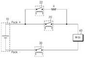
도 1은 배터리 팩과 부하가 릴레이 스위치부를 통해 접속되어 있는 상태를 개념적으로 도시한 회로 도이다.1 is a circuit diagram conceptually illustrating a state in which a battery pack and a load are connected through a relay switch unit.
도 1을 참조하여 종래의 릴레이 스위치부 제어방법을 설명하면 다음과 같다.Referring to Figure 1, the conventional relay switch control method will be described.
먼저, 배터리 팩(10)을 부하(40)에 연결할 때에는 (??)측 릴레이 스위치부(30)를 온 시킨다. 그런 다음, 프리 차지 스위치부(22)를 온 시켜 프리 차지 스위치부(22)와 직렬 연결된 전류제한 저항(R)에 의해 크기 레벨이 제한된 전류를 부하에 인가한다. 이 상태에서 일정한 시간이 경과되면, (+)측 릴레이 스위치부(20)를 온 시키고 프리 차지 스위치부(22)를 턴오프 시킨다.First, when connecting the
여기서, 프리 차지 스위치부(22)를 사용하여 배터리 팩(10)과 부하(40)를 연결하는 이유는 배터리 팩(10)을 부하(40)에 연결할 때 부하(40) 측에 돌입 전류가 인가되는 것을 방지하기 위함이다.Here, the reason for connecting the
반대로, 배터리 팩(10)과 부하(40)의 연결을 해제할 때에는 미리 정해진 순서에 따라 (+)측 및 (-)측 릴레이 스위치부(20, 30)를 턴오프시켜 배터리 팩(10)과 부하(40)의 연결을 해제한다.On the contrary, when disconnecting the
릴레이 스위치부가 턴오프될 때에는 릴레이의 인덕턴스 성분으로 인해 릴레이 스위치부의 접점에서 아크가 발생된다. 발생된 아크는 릴레이 스위치부의 접점에 손상을 줌으로써 릴레이 스위치부의 수명을 단축시킨다.When the relay switch unit is turned off, an arc is generated at the contact point of the relay switch unit due to the inductance component of the relay. The generated arc damages the contact point of the relay switch unit, thereby shortening the life of the relay switch unit.
종래의 릴레이 제어 방법에서는 릴레이 스위치부의 조작 순서가 미리 정해져 있으므로 아크로 인한 릴레이 스위치부의 손상이 어느 한쪽 릴레이 스위치부에 상대적으로 집중된다. 이에 따라, 2개의 릴레이 스위치부 중 어느 한쪽 릴레이 스위치부의 고장 및 오동작 빈도수가 증가하고 스위치부 교체 주기가 단축되는 문제가 있다.In the conventional relay control method, since the operation order of the relay switch unit is predetermined, damage to the relay switch unit due to the arc is relatively concentrated on either relay switch unit. Accordingly, there is a problem that the frequency of failure and malfunction of either of the two relay switch units increases and the switching cycle of the switch unit is shortened.
본 발명은 상기와 같은 종래기술의 문제점을 해결하기 위해 창안된 것으로서, 배터리 팩과 부하를 연결하는데 사용되는 스위치부의 고장 빈도를 줄이고, 부품 사용 수명을 증가시킬 수 있는 배터리 팩과 부하 간의 스위치부 제어장치 및 방법과, 상기 제어장치를 포함하는 배터리 팩 및 배터리 관리 장치를 제공하는데 그 목적이 있다.The present invention has been made to solve the problems of the prior art as described above, switch unit control between the battery pack and the load that can reduce the frequency of failure of the switch used to connect the battery pack and the load, and increase the service life of the parts An object of the present invention is to provide an apparatus and method, and a battery pack and a battery management apparatus including the control apparatus.
상기 기술적 과제를 달성하기 위한 본 발명에 따른 배터리 팩과 부하 간의 스위치부 제어장치는, 배터리 팩과 부하의 연결을 제어하는 제1 및 제2스위치부의 턴오프 회수 및 순서를 전류범위에 따라 저장하는 메모리; 및 방전전류의 크기 레벨이 속한 전류범위에 대응하는 턴오프 회수 및 순서를 상기 메모리로부터 참조하여 상기 제1 및 제2스위치부의 턴오프 순서를 균등화하는 제어부;를 포함한다.Switch unit control device between the battery pack and the load according to the present invention for achieving the above technical problem, the first and second switch unit for controlling the connection of the battery pack and the load to store the turn-off and the order according to the current range Memory; And a control unit equalizing the turn-off order of the first and second switch units by referring to the turn-off number and order corresponding to the current range to which the magnitude level of the discharge current belongs, from the memory.
본 발명에 있어서, 상기 제1스위치부는 배터리 팩의 양극과 부하를 연결한 고전위 선로 상에 설치되고, 상기 제2스위치부는 배터리 팩의 음극과 부하를 연결한 저전위 선로 상에 설치될 수 있다.In the present invention, the first switch unit may be installed on the high potential line connecting the positive electrode and the load of the battery pack, the second switch unit may be installed on the low potential line connecting the negative electrode and the load of the battery pack. .
바람직하게, 상기 제어부는 배터리 팩과 부하의 연결 해제 시 방전전류의 크기 레벨을 검출하고, 메모리에 저장된 전류범위 중 상기 방전전류의 크기 레벨이 속하는 전류범위에 해당하는 스위치부 턴오프 회수와 순서를 메모리로부터 리드하고, 리드된 스위치부 턴오프 회수와 순서를 이용하여 제1 및 제2스위치부의 턴오프 순서를 균등화시킨다.Preferably, the control unit detects the magnitude level of the discharge current when the battery pack and the load are disconnected, and switches the turn-off frequency and the sequence corresponding to the current range to which the magnitude level of the discharge current belongs among the current ranges stored in the memory. It reads from a memory and equalizes the turn-off order of a 1st and 2nd switch part using the number and turn-on of the switch part turn-off which were read.
본 발명의 일 측면에 따르면, 상기 제어부는 제1 및 제2스위치부 중 턴오프 회수가 작은 스위치부터 턴오프시킨다.According to an aspect of the present invention, the control unit turns off the first switch and the small number of turn-off switch of the second switch unit.
본 발명의 다른 측면에 따르면, 상기 제어부는 제1 및 제2스위치부의 턴오프 회수가 동일하면 가장 최근에 턴오프 동작을 하지 않은 스위치부터 턴오프시킨다.According to another aspect of the present invention, if the number of turn-offs of the first and second switch units is the same, the controller turns off the switch that has not been recently turned off.
본 발명에 따른 장치는, 상기 고전위 선로의 바이패스 선로 상에 설치된 프리 차지 스위치부; 및 상기 프리차지 스위치부와 직렬 접속된 전류제한 저항을 더 포함할 수 있다.The apparatus according to the present invention comprises: a precharge switch unit installed on a bypass line of the high potential line; And a current limiting resistor connected in series with the precharge switch unit.
바람직하게, 상기 제어부는 배터리 팩과 부하의 연결 시 제2스위치부, 프리 차지 스위치부 및 제1스위치부 순서로 턴온시키고, 상기 제1스위치부가 턴온되면 일정 시간 이후에 프리 차지 스위치부를 턴오프시킨다.Preferably, the control unit turns on the second switch unit, the precharge switch unit, and the first switch unit in order when the battery pack and the load are connected, and turns off the precharge switch unit after a predetermined time when the first switch unit is turned on. .
바람직하게, 상기 제어부는 배터리 팩과 부하 간의 연결이 해제된 시점을 기준으로 배터리의 방전전류 크기 레벨이 속하는 전류범위에 해당하는 제1 및 제2스위치부의 턴오프 회수 및 순서를 갱신하여 메모리에 저장한다.Preferably, the controller updates the turn-off frequency and the order of turn-off of the first and second switch units corresponding to the current range to which the discharge current magnitude level of the battery belongs, based on the time point at which the connection between the battery pack and the load is released, and stores them in the memory. do.
한편, 본 발명에 따른 스위치부 제어장치는, 배터리 팩 내에 구비되거나, 배터리 관리 장치의 일부 구성요소로 포함될 수 있다.On the other hand, the switch unit control apparatus according to the present invention may be provided in the battery pack, or may be included as some components of the battery management device.
상기 기술적 과제를 달성하기 위한 본 발명에 따른 부하와 배터리 팩의 연결을 제어하는 스위치부 제어방법은, 배터리 팩과 부하를 연결하는 제1 및 제2스위치부의 턴오프 회수 및 순서를 전류범위에 따라 메모리에 저장하여 관리하는 단계; 배터리 팩과 부하의 연결 해제 시 배터리의 방전전류 크기 레벨을 검출하는 단계; 및 검출된 방전전류 크기 레벨이 속하는 전류범위에 해당하는 제1 및 제2스위치부의 턴오프 회수 및 순서를 상기 메모리로부터 참조하여 제1 및 제2스위치부의 턴오프 순서를 균등화시켜 배터리 팩과 부하의 연결을 해제하는 단계;를 포함한다.Switch unit control method for controlling the connection of the load and the battery pack according to the present invention for achieving the above technical problem, the turn-off frequency and order of the first and second switch unit connecting the battery pack and the load according to the current range Storing and managing the memory; Detecting a discharge current level of the battery when the battery pack and the load are disconnected; And equalizing the turn-off order of the first and second switch parts by referring to the turn-off number and order of the first and second switch parts corresponding to the current range to which the detected discharge current magnitude level belongs, from the memory. And disconnecting the connection.
본 발명에 의하면, 배터리 팩과 부하의 연결 해제시 부하 측으로 인가되는 방전전류의 레벨에 따라 스위치부의 턴오프 회수를 균등화함으로써, 스위치부의 고장 또는 오작동 빈도를 줄이고, 스위치부의 사용 수명을 증가시킬 수 있는 효과가 있다.According to the present invention, by equalizing the number of turn-offs of the switch unit in accordance with the level of the discharge current applied to the load side when disconnecting the battery pack and the load, it is possible to reduce the frequency of the switch unit failure or malfunction, and increase the service life of the switch unit It works.
이하, 첨부된 도면을 참조하여 본 발명의 바람직한 실시예를 상세히 설명하기로 한다. 이에 앞서, 본 명세서 및 청구범위에 사용된 용어나 단어는 통상적이거나 사전적인 의미로 한정해서 해석되어서는 아니 되며, 발명자는 그 자신의 발명을 가장 최선의 방법으로 설명하기 위해 용어의 개념을 적절하게 정의할 수 있다는 원칙에 입각하여 본 발명의 기술적 사상에 부합하는 의미와 개념으로 해석되어야만 한다. 따라서, 본 명세서에 기재된 실시예와 도면에 도시된 구성은 본 발명의 가장 바람직한 일 실시예에 불과할 뿐이고 본 발명의 기술적 사상을 모두 대변하는 것은 아니므로, 본 출원시점에 있어서 이들을 대체할 수 있는 다양한 균등물과 변형예들이 있을 수 있음을 이해하여야 한다.Hereinafter, exemplary embodiments of the present invention will be described in detail with reference to the accompanying drawings. Prior to this, terms or words used in the present specification and claims should not be construed as being limited to the common or dictionary meanings, and the inventors should properly explain the concept of terms in order to best explain their own invention. Based on the principle that can be defined, it should be interpreted as meaning and concept corresponding to the technical idea of the present invention. Therefore, the embodiments described in the specification and the drawings shown in the drawings are only the most preferred embodiment of the present invention and do not represent all of the technical idea of the present invention, various modifications that can be replaced at the time of the present application It should be understood that there may be equivalents and variations.
도 2는 본 발명의 바람직한 실시예에 따른 배터리 팩과 부하 간의 스위치부 제어장치를 도시한 회로 구성도이다.2 is a circuit diagram illustrating an apparatus for controlling a switch unit between a battery pack and a load according to an exemplary embodiment of the present invention.
도 2에 도시된 바와 같이, 본 발명에 따른 배터리 팩과 부하 간의 스위치부 제어장치(50)는 부하(40)와 부하(40)에 전원을 공급하는 배터리 팩(10)의 전송선로 상에 배치된 제1스위치부(20), 프리 차지 스위치부(22) 및 제2스위치부(30)의 동작을 전반적으로 제어한다.As shown in FIG. 2, the
상기 제1스위치부(20)는 배터리 팩(10)의 양극과 부하(40)를 연결한 고전위 선로(Pack+) 상에 설치된다. 그리고 상기 제2스위치부(30)는 배터리 팩(10)의 음극과 부하(40)를 연결한 저전위 선로(Pack-) 상에 설치된다. 또한 상기 프리 차지 스위치부(22)는 고전위 선로의 바이 패스 선로(1) 상에 설치되며, 전류 제한 저항(R)과 직렬 접속된다.The
바람직하게, 상기 제1스위치부(20), 프리 차지 스위치부(22) 및 제2스위치부(30)는 릴레이 스위치부로 구성한다. 하지만 본 발명은 배터리 팩(10)과 부하(40)를 연결하는 스위치부의 종류에 의해 한정되지 않는다.Preferably, the
상기 배터리 팩(10)은 반복적인 충방전이 가능한 다수의 단위 셀이 직렬 또는 병렬로 연결된 셀 어셈블리를 포함한다. 상기 단위 셀은 울트라 캐패시터를 포함하는 전기 이중층 캐패시터 또는 리튬 이온 전지, 리튬 폴리머 전지, 니켈 카드늄 전지, 니켈 수소 전지, 니켈 아연 전지 등과 같은 공지의 2차 전지이다.The
상기 부하(40)는 배터리 팩(10)으로부터 전원을 공급받아 동력을 생산하는 모터, 배터리 팩(10)으로부터 인가되는 방전전압을 다른 전압 레벨로 변환하는 DC-DC 컨버터 등이다. 하지만 본 발명은 부하(40)의 종류에 의해 한정되지 않으므로, 부하(40)는 배터리 팩(100으로부터 동작 전원을 인가 받는 어떠한 장치나 시스템도 포함하는 것으로 이해되어야 한다.The
본 발명에 따른 스위치부 제어장치(50)는, 배터리 팩(10)에서 부하(40)로 인가된 방전전류의 크기 레벨 정보와 제1스위치부(20)와 제2스위치부(30)의 턴오프 회수 및 순서(예컨대, 가장 최근 동작 순서)를 저장하는 메모리(54)와, 제1 및 제2스위치부(20, 30)와 프리 차지 스위치부(22)에 동작 제어신호를 인가하여 스위치부들의 동작을 제어하는 제어부(52)를 포함한다.Switch
상기 제어부(52)는 배터리 팩(10)과 부하(40)를 연결할 때에는 제2스위치부(30), 프리 차지 스위치부(22), 및 제1스위치부(20) 순서로 스위치부를 턴온시키고, 제1스위치부(20)가 턴온되면 일정 시간 이후에 프리 차지 스위치부(22)를 턴오 프시킨다. 이러한 스위치부 조작 순서는 도 1을 참조하여 설명한 종래의 스위치부 제어 방법과 동일하다.When the
상기 제어부(52)는 배터리 팩(10)과 부하(40) 사이의 연결을 해제할 때 제1 및 제2스위치부(20, 30)의 턴오프 순서를 일정하게 유지하지 않고 배터리 팩(10)에서 부하(40)로 인가된 방전전류의 크기 레벨과 함께 방전전류의 크기 레벨에 따른 과거의 스위치부 턴오프 회수와 순서를 메모리(54)로부터 참조하여 현재의 스위치부 턴오프 순서를 변경함으로써 방전전류의 크기 레벨에 따라 제1 및 제2스위치부(20, 30)의 턴오프 순서를 균등화시킨다.When the
즉, 상기 제어부(52)는 상기 배터리 팩(10)과 부하(40)의 연결 해제 요청이 있으면 배터리 팩(10)에서 부하(40)로 인가된 방전전류의 크기 레벨을 검출하여 방전전류의 크기 레벨이 속하는 전류범위를 메모리(54)에서 식별한다. 그런 다음, 상기 제어부(52)는 식별된 전류범위에 대응하는 제1 및 제2스위치부(20, 30)의 과거 턴오프 회수 및 순서를 상기 메모리(54)로부터 리드한다. 상기 연결 해제 요청은 배터리 관리 장치 등의 외부 장치로부터 입력될 수도 있고, 상기 제어부(52) 내에서 미리 스케쥴링되어 발생될 수도 있다. 그런 다음, 상기 제어부(52)는 제1스위치부(20)와 제2스위치부(30)의 과거 턴오프 회수 및 순서를 고려하여 턴오프 회수가 작은 스위치부터 턴오프 시킨다. 한편, 턴오프 회수가 동일할 경우에는 가장 최근에 턴오프되지 않은 스위치부부터 턴오프시켜 배터리 팩(10)과 부하(40)의 연결을 해제한다. 또한, 상기 제어부(52)는 배터리 팩(10)과 부하(40)간의 연결이 해제된 현재 시점을 기준으로 배터리의 방전전류 크기 레벨이 속하는 전류범위에 해당하는 제1 및 제2스위치부(20, 30)의 턴오프 회수 및 순서 정보를 갱신하여 메모리(54)에 저장하고 배터리 팩(10)과 부하(40)간의 연결 해제 동작을 완료한다.That is, the
하기 표 1은 방전전류의 전류범위 별로 대응하는 스위치부의 턴오프 회수 및 순서 정보의 일 예를 보여준다. 하기 표 1에서, 괄호 안의 수 0은 스위치부가 가장 최근에 턴오프 동작을 하지 않았다는 것을 의미하고, 1은 스위치부가 가장 최근에 턴오프 동작을 했다는 것을 의미한다. 예를 들어, Middle 전류 범위의 경우 직전에 배터리 팩과 부하의 연결을 해제할 때에는 제2스위치부를 먼저 턴오프하고, 그 다음으로 제1스위치부를 턴오프하였음을 의미한다. 물론, 가장 최근의 스위치부 턴오프 순서를 나타나는 코드 체계는 상기한 바에 한정되지 않고 여러 가지 변형이 가능하다. 상기 스위치부의 턴오프 회수 및 순서 정보는 메모리(54)에 디지털 데이터로 저장된다.Table 1 shows an example of turn-off frequency and order information of the switch unit corresponding to each current range of the discharge current. In Table 1 below, the number 0 in parentheses means that the switch unit has not recently turned off, and 1 means that the switch unit has recently turned off. For example, in the case of the middle current range, when the battery pack and the load are disconnected immediately before, the second switch unit is turned off first and then the first switch unit is turned off. Of course, the code system showing the most recent switch-off turn-off order is not limited to the above, and various modifications are possible. The turn off count and order information of the switch unit are stored in the
(최근 작동 여부)Number of turn-offs of the first switch unit
(Will it work recently)
(최근 작동 여부)Number of turn-offs of the second switch unit
(Will it work recently)
[표 1]TABLE 1
상기 표1과 도 2를 참조하여 스위치부의 턴오프 순서 제어 과정을 좀더 구체적으로 설명하면 다음과 같다.Turning to the turn-off sequence control process of the switch unit with reference to Table 1 and Figure 2 in more detail as follows.
일 예로, 배터리 팩(10)에서 부하(40)로 인가된 방전전류의 크기 레벨이 5A 였다고 가정하자. 이런 경우, 제어부(52)는 메모리(54)에 저장된 전류범위 중 5A가 속하는 전류범위인 Low 범위의 제1 및 제2스위치부(20, 30)의 턴오프 회수 정보를 리드한다. 상기 표1에 따르면, 제1스위치부(20)의 턴오프 회수는 제2스위치부(30)의 턴오프 회수보다 1이 작다. 따라서 제어부(52)는 제1스위치부(20)와 제2스위치부(30)의 턴오프 회수를 비교하고 제2스위치부(30) 보다 턴오프 회수가 1회 적은 제1스위치부(20)를 먼저 턴오프시킨 후 제2스위치부(30)를 턴오프 시킨다.As an example, assume that the magnitude level of the discharge current applied from the
다른 예로, 배터리 팩(10)에서 부하(40)로 인가된 방전전류의 크기 레벨이 30A 였다고 가정하다. 이런 경우, 제어부(52)는 메모리(54)에 저장된 전류범위 중 30A가 속하는 Middle 범위의 제1 및 제2스위치부(20, 30)의 턴오프 회수를 리드한다. 상기 표1에 따르면, 제2스위치부(30)의 턴오프 회수가 제1스위치부(20)의 턴오프 회수보다 1이 작다. 따라서 상기 제어부(52)는 제1스위치부(20)와 제2스위치부(30)의 턴오프 회수를 비교하고 턴오프 회수가 제1스위치부(20) 보다 1회 적은 제2스위치부(30)를 먼저 턴오프시킨 후 제1스위치부(20)를 턴오프 시킨다.As another example, it is assumed that the magnitude level of the discharge current applied from the
또 다른 예로, 배터리 팩(10)에서 부하(40)로 인가된 방전전류의 크기 레벨이 60A 였다고 가정하자. 이런 경우, 제어부(52)는 메모리(54)에 저장된 전류범위 중 60A가 속하는 High 범위의 제1 및 제2스위치부(20, 30)의 턴오프 회수를 리드한다. 상기 표1에 따르면, 제1스위치부(20)와 제2스위치부(30)의 턴오프 회수가 같다. 이런 경우, 제어부(52)는 제1스위치부(20) 및 제2스위치부(30)의 턴오프 순서를 메모리(54)로부터 리드하여 제1스위치부(20)와 제2스위치부(30)중 가장 최근에 턴오프 동작을 하지 않은 스위치부를 식별하고 식별된 스위치부부터 먼저 턴오프 동작시킨다. 즉, 상기 제어부(52)는 제2스위치부(30)가 가장 최근에 턴오프 동작을 하였으므로 제1스위치부(20)를 먼저 턴오프시킨 후 그 다음으로 제2스위치부(30)를 턴오프 시킨다.As another example, assume that the magnitude level of the discharge current applied from the
상기에서 설명된 실시예에서, Low, Middle, High로 설정된 전류 범위는 본 발명을 설명하기 위한 일 예시에 불과하다. 따라서, 전류범위는 다양하게 설계 변경이 가능함은 물론이다.In the embodiment described above, the current range set to Low, Middle, High is only one example for explaining the present invention. Therefore, it is a matter of course that the current range can be changed in various ways.
한편, 도 2에는 배터리 팩(10)으로부터 부하(40) 측으로 흐르는 방전전류의 크기 레벨을 측정하여 메모리(54)에 저장하기 위한 구성이 도시되어 있지 않다. 하지만 방전전류의 측정 기술은 공지된 기술로 용이하게 구현 가능하다.2 illustrates a configuration for measuring the magnitude level of the discharge current flowing from the
일 예로, 방전전류가 흐르는 선로에 전류 센서를 설치하고 전류 센서가 출력하는 방전전류 값을 제어부(52)가 입력 받아 메모리(54)에 저장할 수 있다. 다른 예로, 방전전류가 흐르는 선로 상에 전류 측정용 저항을 설치하고 제어부(54)가 저항을 알고 있는 전류 측정용 저항의 양단 전압을 검출하여 오옴의 법칙에 의해 방전전류 값을 계산한 후 메모리(54)에 저장할 수 있다. 또 다른 예로, 상기 제어부는 부하(40)가 장착된 장치로부터 방전전류 값을 입력받아 메모리(54)에 저장할 수도 있다. 예컨대, 부하(40)가 자동차의 모터인 경우 자동차에 탑재된 배터리 관리 장치는 모터로 공급되는 방전전류를 검출하여 그 값을 지속적으로 모니터링하므로 상기 제어부(52)는 통신 인터페이스를 통해 상기 배터리 관리 장치로부터 방전전류 값을 전송 받아 메모리(54)에 저장할 수도 있다. 이 이외에도 제어부(52)가 방전전류의 크기 레벨을 획득하는 방식은 여러 가지 변형이 가능할 것임은 본 발명이 속한 기술분야에서 통상의 지식을 가진 자에게 자명하다.For example, the current sensor may be installed on a line through which the discharge current flows, and the
상술한 본 발명에 따른 스위치부 제어장치는 배터리 팩 내에 구비될 수도 있 고, 배터리의 충방전을 제어하는 배터리 관리 장치 내에 포함될 수도 있다. 따라서 본 발명은 상기 스위치부 제어장치의 설치 위치에 한정되지 않음은 자명하다.The switch control device according to the present invention described above may be provided in the battery pack, it may be included in the battery management device for controlling the charge and discharge of the battery. Therefore, it is obvious that the present invention is not limited to the installation position of the switch control device.
도 3은 본 발명의 바람직한 실시예에 따른 배터리 팩과 부하 간의 스위치부 제어방법을 도시한 흐름도이다.3 is a flowchart illustrating a method of controlling a switch unit between a battery pack and a load according to an exemplary embodiment of the present invention.
먼저, 단계(S100)에서 배터리 팩과 부하의 연결 해제 요청이 있으면 제어부(52)는 메모리로(54)부터 배터리 팩(10)에서 부하(40)로 인가되는 방전전류 크기 레벨 정보를 리드하고, 리드된 방전전류 크기 레벨이 속하는 전류범위에 해당하는 제1 및 제2스위치부(20, 30) 턴오프 회수 및 순서 정보를 리드한다.First, if there is a request to disconnect the battery pack and the load in step S100, the
다음으로, 단계(S200)에서 제어부(52)는 리드된 전류범위의 제1 및 제2스위치부(20, 30)의 턴오프 회수가 동일한지를 판단한다.Next, in step S200, the
상기 S200 단계에서 제1 및 제2스위치부(20, 30)의 턴오프 회수가 동일하지 않은 것으로 판단되면, 단계(S300)으로 이행하여 턴오프 회수가 적은 스위치부터 턴오프하여 배터리 팩(10)과 부하(40)의 연결을 완전히 해제한다.If it is determined in step S200 that the number of turn-offs of the first and
단계(S400)에서는, 방전전류의 크기 레벨이 속한 전류범위에 해당하는 제1 및 제2스위치부(20, 30)의 턴오프 회수 및 순서 정보를 갱신하여 메모리(54)에 저장한다. 단계(S400)을 진행하는 목적은 차후에 배터리 팩과 부하의 연결을 해제할 때 턴오프 회수와 순서 정보를 참고하기 위함이다.In step S400, the turn-off frequency and order information of the first and
한편, 상기 S200 단계에서 제1 및 제2스위치부(20, 30)의 턴오프 회수가 동일한 것으로 판단되면, 단계(S500)으로 이행하여 제1 및 제2스위치부(20, 30)의 턴오프 순서로부터 가장 최근에 턴오프 동작을 한 스위치부를 식별하고, 최근에 턴오 프되지 않은 스위치부부터 턴오프시켜 배터리 팩(10)과 부하(40)의 연결을 완전히 해제한다. 예를 들어, 제1스위치부(20)가 가장 최근에 턴오프 동작을 하였다면, 제2스위치부(30)부터 턴오프시켜 배터리 팩(10)과 부하(40)의 연결을 완전히 해제한다.On the other hand, if it is determined that the turn-off times of the first and
단계(S600)에서는, 방전전류의 크기 레벨이 속한 전류범위에 해당하는 제1 및 제2스위치부(20, 30)의 턴오프 회수 및 순서 정보를 갱신하여 메모리(54)에 저장한다. 단계(S600)을 진행하는 목적은 차후에 배터리 팩과 부하의 연결을 해제할 때 턴오프 회수와 순서 정보를 참고하기 위함이다.In step S600, the turn-off frequency and order information of the first and
상술한 바와 같이, 배터리 팩(10)과 부하(40)를 연결하는 제1 및 제2스위치부(20, 30)를 방전전류의 크기 레벨에 따라 균등하게 턴오프 시키면 아크 손상의 상대적 집중으로 인해 특정 스위치부의 고장 또는 오작동 빈도수가 증가하고, 스위치부 사용 수명이 감소되는 현상을 방지할 수 있다.As described above, if the first and
특히, 본 발명은 스위치부의 턴오프 회수와 순서를 방전전류의 레벨에 따라 차등적으로 관리함으로써 스위치부 손상의 편중을 더욱 효과적으로 방지할 수 있다. 즉 전류범위에 구분을 두지 않고 스위치부의 턴오프 순서를 관리하면, 전체 턴오프 회수가 작은 스위치부터 턴오프 되더라도 스위치부 손상의 편중이 발생될 수 있다. 전체 턴오프 회수가 작은 스위치부라도 방전전류가 큰 환경에서 턴오프된 경우가 많다면 전체 턴오프 회수가 많은 스위치부보다 스위치부 손상이 더 클 수 있기 때문이다. 하지만 본 발명은 방전전류의 크기 레벨에 따라 턴오프 회수를 균등화시키므로 위와 같은 문제를 근본적으로 해결할 수 있다.In particular, the present invention can more effectively prevent the bias of the switch unit damage by managing the turn-off frequency and the order of the switch unit differentially according to the level of the discharge current. That is, if the turn-off order of the switch unit is managed without making a distinction in the current range, even if the total turn-off number is turned off from the small switch, bias of the switch unit may occur. This is because damage to the switch may be greater than that of the switch which has a large number of turn-offs, even when the switch portion having a small total turn-off is often turned off in a large discharge current environment. However, the present invention can fundamentally solve the above problem because the number of turn-off is equalized according to the magnitude level of the discharge current.
이상에서 본 발명은 비록 한정된 실시예와 도면에 의해 설명되었으나, 본 발명은 이것에 의해 한정되지 않으며 본 발명이 속하는 기술분야에서 통상의 지식을 가진 자에 의해 본 발명의 기술사상과 아래에 기재될 특허청구범위의 균등범위 내에서 다양한 수정 및 변형이 가능함은 물론이다.Although the present invention has been described above by means of limited embodiments and drawings, the present invention is not limited thereto and will be described below by the person skilled in the art to which the present invention pertains. Of course, various modifications and variations are possible within the scope of the claims.
본 명세서에 첨부되는 다음의 도면들은 본 발명의 바람직한 실시예를 예시하는 것이며, 전술된 발명의 상세한 설명과 함께 본 발명의 기술사상을 더욱 이해시키는 역할을 하는 것이므로, 본 발명은 그러한 도면에 기재된 사항에만 한정되어 해석되지 않아야 한다.The following drawings, which are attached to this specification, illustrate exemplary embodiments of the present invention, and together with the detailed description of the present invention serve to further understand the technical spirit of the present invention, the present invention includes matters described in such drawings. It should not be construed as limited to.
도 1은 배터리 팩과 부하가 릴레이 스위치부를 통해 접속되어 있는 상태를 개념적으로 도시한 회로도이다.1 is a circuit diagram conceptually illustrating a state in which a battery pack and a load are connected through a relay switch unit.
도 2는 본 발명의 바람직한 실시예에 따른 배터리 팩과 부하 간의 스위치부 제어장치를 도시한 회로 구성도이다.2 is a circuit diagram illustrating an apparatus for controlling a switch unit between a battery pack and a load according to an exemplary embodiment of the present invention.
도 3은 본 발명의 바람직한 실시예에 따른 배터리 팩과 부하 간의 스위치부 제어방법을 설명하기 위해 도시한 흐름도이다.3 is a flowchart illustrating a method of controlling a switch unit between a battery pack and a load according to an exemplary embodiment of the present invention.
Claims (17)
Translated fromKoreanPriority Applications (6)
| Application Number | Priority Date | Filing Date | Title |
|---|---|---|---|
| PCT/KR2009/004926WO2010024653A2 (en) | 2008-09-01 | 2009-09-01 | Apparatus and method for controlling a switch unit between battery pack and a load, and battery pack and battery management apparatus including the apparatus |
| EP09810258.5AEP2322375B1 (en) | 2008-09-01 | 2009-09-01 | Apparatus and method for controlling a switch unit between battery pack and a load, and battery pack and battery management apparatus including the apparatus |
| CN2009801342361ACN102137772B (en) | 2008-09-01 | 2009-09-01 | Device and method for controlling switching unit between battery pack and load, battery pack and battery management device including the device |
| JP2011524915AJP5507562B2 (en) | 2008-09-01 | 2009-09-01 | Switch unit control device and method, and battery pack and battery management device including the device |
| US12/699,147US8564156B2 (en) | 2008-09-01 | 2010-02-03 | Apparatus and method of controlling switch units, and battery pack and battery management apparatus comprising said apparatus |
| US14/032,416US8896160B2 (en) | 2008-09-01 | 2013-09-20 | Apparatus and method of controlling switch units, and battery pack and battery management apparatus comprising said apparatus |
Applications Claiming Priority (2)
| Application Number | Priority Date | Filing Date | Title |
|---|---|---|---|
| KR20080085762 | 2008-09-01 | ||
| KR1020080085762 | 2008-09-01 |
Publications (2)
| Publication Number | Publication Date |
|---|---|
| KR20100027084A KR20100027084A (en) | 2010-03-10 |
| KR101028291B1true KR101028291B1 (en) | 2011-04-11 |
Family
ID=42178229
Family Applications (1)
| Application Number | Title | Priority Date | Filing Date |
|---|---|---|---|
| KR1020090082215AActiveKR101028291B1 (en) | 2008-09-01 | 2009-09-01 | Switch unit control and method between the battery pack and the load, and a battery pack and battery management device comprising the device |
Country Status (6)
| Country | Link |
|---|---|
| US (2) | US8564156B2 (en) |
| EP (1) | EP2322375B1 (en) |
| JP (1) | JP5507562B2 (en) |
| KR (1) | KR101028291B1 (en) |
| CN (1) | CN102137772B (en) |
| WO (1) | WO2010024653A2 (en) |
Cited By (1)
| Publication number | Priority date | Publication date | Assignee | Title |
|---|---|---|---|---|
| WO2013089517A1 (en)* | 2011-12-16 | 2013-06-20 | (주)브이이엔에스 | Electric vehicle and method for controlling same |
Families Citing this family (43)
| Publication number | Priority date | Publication date | Assignee | Title |
|---|---|---|---|---|
| CN102137772B (en)* | 2008-09-01 | 2013-08-21 | 株式会社Lg化学 | Device and method for controlling switching unit between battery pack and load, battery pack and battery management device including the device |
| US11901810B2 (en) | 2011-05-08 | 2024-02-13 | Koolbridge Solar, Inc. | Adaptive electrical power distribution panel |
| US12362647B2 (en) | 2011-05-08 | 2025-07-15 | Koolbridge Solar, Inc. | Solar energy system with variable priority circuit backup |
| US8937822B2 (en) | 2011-05-08 | 2015-01-20 | Paul Wilkinson Dent | Solar energy conversion and utilization system |
| JP5605320B2 (en)* | 2011-06-28 | 2014-10-15 | 株式会社オートネットワーク技術研究所 | Vehicle power supply |
| JP2013038871A (en)* | 2011-08-05 | 2013-02-21 | Sanyo Electric Co Ltd | Switching device |
| US8912682B2 (en)* | 2011-08-25 | 2014-12-16 | Hamilton Sundstrand Corporation | Power management and distribution center for constant power loads |
| JP5288041B1 (en)* | 2011-09-21 | 2013-09-11 | トヨタ自動車株式会社 | Power storage system and method for controlling power storage system |
| KR102093683B1 (en)* | 2012-01-12 | 2020-03-27 | 에스케이이노베이션 주식회사 | Power Relay Assembly. |
| JP5787176B2 (en)* | 2012-04-05 | 2015-09-30 | 株式会社デンソー | Vehicle power supply control device |
| EP2762347A1 (en)* | 2013-01-31 | 2014-08-06 | Siemens Aktiengesellschaft | Modular high frequency converter and method for operating the same |
| CN103072464B (en)* | 2013-02-05 | 2015-09-09 | 安徽安凯汽车股份有限公司 | A kind of series hybrid electric vehicle high-pressure system power-on and power-off control circuit and control method |
| KR20140125944A (en)* | 2013-04-19 | 2014-10-30 | 삼성에스디아이 주식회사 | Battery module and control method thereof |
| KR20150028095A (en) | 2013-09-05 | 2015-03-13 | 주식회사 엘지화학 | Apparatus and method for calculating precharge resistor of battery pack |
| CN103746542A (en)* | 2013-12-31 | 2014-04-23 | 芜湖国睿兆伏电子有限公司 | Circuit for eliminating pulse impacting of pulse transformer |
| US9731609B2 (en) | 2014-04-04 | 2017-08-15 | Dg Systems Llc | Vehicle power sharing and grid connection system for electric motors and drives |
| CN104827920B (en)* | 2014-10-27 | 2017-06-06 | 北汽福田汽车股份有限公司 | The dynamical system of electric car and the electric car with it |
| KR101594925B1 (en) | 2014-12-03 | 2016-02-17 | 삼성에스디아이 주식회사 | Battery pack |
| EP3038226B1 (en)* | 2014-12-26 | 2022-08-03 | Fico Triad, S.A. | System and method for supplying electric power |
| CN105984353B (en)* | 2015-02-09 | 2018-12-25 | 台达电子工业股份有限公司 | Battery power supply integration device and oil-electricity hybrid vehicle power supply system with same |
| CN105006851A (en)* | 2015-08-28 | 2015-10-28 | 常州格力博有限公司 | Lithium battery management system and control method thereof |
| US20160031323A1 (en)* | 2015-10-09 | 2016-02-04 | Caterpillar Inc. | System and method of controlling contactor tip assembly |
| KR102528423B1 (en)* | 2015-12-09 | 2023-05-03 | 현대모비스 주식회사 | Battery Management System for reducing noise and method thereof |
| US10449867B2 (en)* | 2015-12-15 | 2019-10-22 | Faraday & Future Inc. | Systems and methods for connecting battery strings to a DC bus |
| KR102237376B1 (en) | 2016-09-08 | 2021-04-06 | 삼성에스디아이 주식회사 | Battery pack |
| KR102260829B1 (en)* | 2016-09-20 | 2021-06-03 | 삼성에스디아이 주식회사 | Battery pack |
| US10516189B2 (en)* | 2016-11-15 | 2019-12-24 | Ford Global Technologies, Llc | High voltage bus contactor fault detection |
| KR102303124B1 (en)* | 2016-11-30 | 2021-09-16 | 주식회사 엘지화학 | Battery pack power cut-off circuit when immersing electric vehicle |
| EP3336869B1 (en)* | 2016-12-15 | 2019-06-19 | General Electric Technology GmbH | Switching apparatus |
| CN107894572B (en)* | 2017-11-10 | 2019-11-12 | 宁德时代新能源科技股份有限公司 | Battery pack fault detection method and device, high voltage box, battery pack and vehicle |
| KR102256094B1 (en)* | 2017-11-28 | 2021-05-25 | 주식회사 엘지에너지솔루션 | Battery back |
| KR102301218B1 (en)* | 2018-01-30 | 2021-09-10 | 주식회사 엘지에너지솔루션 | Apparatus for diagnosing relay drive circuit |
| KR102593366B1 (en)* | 2018-10-18 | 2023-10-23 | 주식회사 엘지에너지솔루션 | System and method for measuring multiple signal |
| JP7252807B2 (en)* | 2019-03-27 | 2023-04-05 | 株式会社Subaru | power system |
| KR102789132B1 (en)* | 2019-10-22 | 2025-03-28 | 주식회사 엘지에너지솔루션 | Controlling Apparatus for turn-on operation of Switch means included in Parallel Multi Battery Pack and Method thereof |
| CN111416331B (en)* | 2020-03-26 | 2022-06-03 | 上海空间电源研究所 | A pre-charge circuit for DC power surge current suppression |
| CN111591169B (en)* | 2020-05-29 | 2022-11-04 | 重庆长安新能源汽车科技有限公司 | Power battery high-voltage loop, control method and electric automobile |
| CN111786439A (en)* | 2020-07-31 | 2020-10-16 | 中车青岛四方机车车辆股份有限公司 | A precharging circuit, charging system, precharging method and train |
| CN113285509B (en)* | 2021-05-27 | 2023-03-03 | 东莞市科旺科技股份有限公司 | Charging pile power distribution control system with self-learning function and charging pile power distribution control method |
| EP4412026A1 (en)* | 2023-02-01 | 2024-08-07 | ABB E-mobility B.V. | Dc contactor arrangement for bidirectional power switching |
| CN116512914A (en)* | 2023-07-05 | 2023-08-01 | 岚图汽车科技有限公司 | Control method and control device for relay for power battery |
| CN117293955B (en)* | 2023-09-21 | 2024-06-04 | 浙江启辰新能科技有限公司 | Energy storage direct current cutting-off method |
| KR20250141337A (en)* | 2024-03-20 | 2025-09-29 | 주식회사 엘지에너지솔루션 | Battery system and operating method thereof |
Citations (3)
| Publication number | Priority date | Publication date | Assignee | Title |
|---|---|---|---|---|
| JP2005295697A (en)* | 2004-03-31 | 2005-10-20 | Sanyo Electric Co Ltd | Power supply device for vehicle |
| KR20070047384A (en)* | 2005-11-02 | 2007-05-07 | 현대자동차주식회사 | Fault diagnosis method of electric power system for hybrid vehicle and electric power system for hybrid vehicle |
| KR20080037941A (en)* | 2006-10-27 | 2008-05-02 | 현대자동차주식회사 | Leakage Current Measurement Apparatus and Method of Energy Storage in Hybrid Fuel Cell Vehicle Using Precharger |
Family Cites Families (22)
| Publication number | Priority date | Publication date | Assignee | Title |
|---|---|---|---|---|
| JP2593318B2 (en)* | 1987-09-16 | 1997-03-26 | 京セラ株式会社 | Control system of photovoltaic power generator |
| JPH0295142A (en)* | 1988-09-28 | 1990-04-05 | Kyocera Corp | Charging control device for solar power generation system |
| JP3641280B2 (en)* | 1992-10-30 | 2005-04-20 | インテル・コーポレーション | Method for determining blocks to be cleaned up in a flash EEPROM array |
| GB2275367B (en)* | 1993-02-22 | 1997-06-25 | Yang Tai Her | D.C. Cut-off switch extinguishing arc circuit |
| DE4340632A1 (en)* | 1993-11-30 | 1995-06-01 | Abb Patent Gmbh | Electrical switching device |
| JPH08126213A (en)* | 1994-10-26 | 1996-05-17 | Nissin Electric Co Ltd | Insulating power supply |
| KR980012814A (en)* | 1996-07-23 | 1998-04-30 | 이대원 | The initial charging device of the converter system |
| JP2002010682A (en)* | 2000-06-16 | 2002-01-11 | Aisin Seiki Co Ltd | Motor energization control device |
| TWI228340B (en)* | 2003-08-08 | 2005-02-21 | Ind Tech Res Inst | Voltage balance circuit for rechargeable batteries |
| US7360848B2 (en)* | 2004-04-16 | 2008-04-22 | Advics Co., Ltd. | Parallel relay circuit for hydraulic braking device |
| KR101091268B1 (en)* | 2005-04-25 | 2011-12-07 | 주식회사 엘지화학 | How to care for battery packs for HE and EV |
| KR100671208B1 (en)* | 2005-08-19 | 2007-01-19 | 삼성전자주식회사 | Electronic device and control method |
| JP2007245966A (en)* | 2006-03-16 | 2007-09-27 | Nissan Motor Co Ltd | Vehicle drive control device |
| JP4702155B2 (en)* | 2006-04-14 | 2011-06-15 | トヨタ自動車株式会社 | Power supply device and control method of power supply device |
| JP5013794B2 (en)* | 2006-09-19 | 2012-08-29 | プライムアースEvエナジー株式会社 | Battery pack |
| US7586214B2 (en)* | 2006-10-11 | 2009-09-08 | Gm Global Technology Operations, Inc. | High voltage energy storage connection monitoring system and method |
| JP2008154371A (en)* | 2006-12-18 | 2008-07-03 | Toyota Motor Corp | VEHICLE DRIVE DEVICE, VEHICLE DRIVE DEVICE CONTROL METHOD, PROGRAM FOR CAUSING COMPUTER TO EXECUTE VEHICLE DRIVE DEVICE CONTROL METHOD, AND RECORDING MEDIUM CONTAINING THE PROGRAM readable |
| US20090230765A1 (en)* | 2008-03-14 | 2009-09-17 | Ford Global Technologies, Llc | System and method for delivering power to an electric motor of an automotive vehicle |
| CN101330225B (en)* | 2008-07-08 | 2010-07-07 | 奇瑞汽车股份有限公司 | Apparatus for monitoring high voltage output of power battery |
| CN102137772B (en)* | 2008-09-01 | 2013-08-21 | 株式会社Lg化学 | Device and method for controlling switching unit between battery pack and load, battery pack and battery management device including the device |
| US8008802B2 (en)* | 2009-03-03 | 2011-08-30 | Leonard Thomas W | Bi-level switching with power packs |
| EP2428387A4 (en)* | 2009-04-23 | 2017-03-22 | Toyota Jidosha Kabushiki Kaisha | Power supply system of electric vehicle and control method thereof |
- 2009
- 2009-09-01CNCN2009801342361Apatent/CN102137772B/enactiveActive
- 2009-09-01WOPCT/KR2009/004926patent/WO2010024653A2/enactiveApplication Filing
- 2009-09-01JPJP2011524915Apatent/JP5507562B2/enactiveActive
- 2009-09-01EPEP09810258.5Apatent/EP2322375B1/enactiveActive
- 2009-09-01KRKR1020090082215Apatent/KR101028291B1/enactiveActive
- 2010
- 2010-02-03USUS12/699,147patent/US8564156B2/enactiveActive
- 2013
- 2013-09-20USUS14/032,416patent/US8896160B2/enactiveActive
Patent Citations (3)
| Publication number | Priority date | Publication date | Assignee | Title |
|---|---|---|---|---|
| JP2005295697A (en)* | 2004-03-31 | 2005-10-20 | Sanyo Electric Co Ltd | Power supply device for vehicle |
| KR20070047384A (en)* | 2005-11-02 | 2007-05-07 | 현대자동차주식회사 | Fault diagnosis method of electric power system for hybrid vehicle and electric power system for hybrid vehicle |
| KR20080037941A (en)* | 2006-10-27 | 2008-05-02 | 현대자동차주식회사 | Leakage Current Measurement Apparatus and Method of Energy Storage in Hybrid Fuel Cell Vehicle Using Precharger |
Cited By (1)
| Publication number | Priority date | Publication date | Assignee | Title |
|---|---|---|---|---|
| WO2013089517A1 (en)* | 2011-12-16 | 2013-06-20 | (주)브이이엔에스 | Electric vehicle and method for controlling same |
Also Published As
| Publication number | Publication date |
|---|---|
| KR20100027084A (en) | 2010-03-10 |
| CN102137772A (en) | 2011-07-27 |
| US8564156B2 (en) | 2013-10-22 |
| CN102137772B (en) | 2013-08-21 |
| US8896160B2 (en) | 2014-11-25 |
| WO2010024653A2 (en) | 2010-03-04 |
| JP5507562B2 (en) | 2014-05-28 |
| EP2322375B1 (en) | 2016-03-30 |
| US20100133914A1 (en) | 2010-06-03 |
| WO2010024653A3 (en) | 2010-06-17 |
| EP2322375A4 (en) | 2014-07-09 |
| JP2012501620A (en) | 2012-01-19 |
| US20140021800A1 (en) | 2014-01-23 |
| EP2322375A2 (en) | 2011-05-18 |
Similar Documents
| Publication | Publication Date | Title |
|---|---|---|
| KR101028291B1 (en) | Switch unit control and method between the battery pack and the load, and a battery pack and battery management device comprising the device | |
| JP2012501620A5 (en) | ||
| JP5911673B2 (en) | Power supply | |
| KR102000237B1 (en) | Electrical system and method for operating an electrical system | |
| US20120091963A1 (en) | Battery fault tolerant architecture for cell failure modes parallel bypass circuit | |
| KR101894979B1 (en) | Vehicle electrical system | |
| KR101841559B1 (en) | Method for operation of an onboard power supply | |
| KR101610921B1 (en) | Apparatus for measuring isolation resistance using selective switching and method thereof | |
| JP6541310B2 (en) | Module control device, balance correction system and storage system | |
| WO2009020367A1 (en) | Apparatus and method for sensing battery cell voltage using isolation capacitor | |
| KR101866063B1 (en) | System for controlling relay of an auxiliary battery and method thereof | |
| EP3972074B1 (en) | Apparatus and method for controlling turn-on operation of switch units included in parallel multi-battery pack | |
| WO2012043590A1 (en) | Power supply device | |
| CN103430419A (en) | Balance correction device, power storage system, and transportation device | |
| CN213082961U (en) | A power battery integrated system and vehicle power supply system | |
| JP2012084443A (en) | Power supply device | |
| CN110198868A (en) | Battery unit and method for running battery unit | |
| CN115441542B (en) | Control method of lithium battery system with variable structure | |
| JP6170984B2 (en) | Power storage device, transport device and control method | |
| KR20230106346A (en) | Battery apparatus and battery management system for measuring insulation resistance | |
| CN109066852B (en) | System and method for improving discharge capacity of high-rate discharge power storage battery | |
| TW201126856A (en) | Battery protecting method and system | |
| Amjadi | Suitability of Switched Capacitor Converters for Electric Vehicle Energy Storage | |
| JP2025103704A (en) | Electricity storage device and electricity storage system | |
| CN118867586A (en) | A sodium ion battery pack and power management method |
Legal Events
| Date | Code | Title | Description |
|---|---|---|---|
| A201 | Request for examination | ||
| PA0109 | Patent application | Patent event code:PA01091R01D Comment text:Patent Application Patent event date:20090901 | |
| PA0201 | Request for examination | ||
| PG1501 | Laying open of application | ||
| E902 | Notification of reason for refusal | ||
| PE0902 | Notice of grounds for rejection | Comment text:Notification of reason for refusal Patent event date:20101228 Patent event code:PE09021S01D | |
| E701 | Decision to grant or registration of patent right | ||
| PE0701 | Decision of registration | Patent event code:PE07011S01D Comment text:Decision to Grant Registration Patent event date:20110330 | |
| GRNT | Written decision to grant | ||
| PR0701 | Registration of establishment | Comment text:Registration of Establishment Patent event date:20110401 Patent event code:PR07011E01D | |
| PR1002 | Payment of registration fee | Payment date:20110401 End annual number:3 Start annual number:1 | |
| PG1601 | Publication of registration | ||
| FPAY | Annual fee payment | Payment date:20140318 Year of fee payment:4 | |
| PR1001 | Payment of annual fee | Payment date:20140318 Start annual number:4 End annual number:4 | |
| FPAY | Annual fee payment | Payment date:20170328 Year of fee payment:7 | |
| PR1001 | Payment of annual fee | Payment date:20170328 Start annual number:7 End annual number:7 | |
| FPAY | Annual fee payment | Payment date:20180403 Year of fee payment:8 | |
| PR1001 | Payment of annual fee | Payment date:20180403 Start annual number:8 End annual number:8 | |
| FPAY | Annual fee payment | Payment date:20190401 Year of fee payment:9 | |
| PR1001 | Payment of annual fee | Payment date:20190401 Start annual number:9 End annual number:9 | |
| PR1001 | Payment of annual fee | Payment date:20200401 Start annual number:10 End annual number:10 | |
| PR1001 | Payment of annual fee | Payment date:20210401 Start annual number:11 End annual number:11 | |
| PR1001 | Payment of annual fee | Payment date:20230323 Start annual number:13 End annual number:13 | |
| PR1001 | Payment of annual fee | Payment date:20240319 Start annual number:14 End annual number:14 |