KR101027233B1 - Reference Signal Transmission Method in Multi-antenna System - Google Patents
Reference Signal Transmission Method in Multi-antenna SystemDownload PDFInfo
- Publication number
- KR101027233B1 KR101027233B1KR1020080124417AKR20080124417AKR101027233B1KR 101027233 B1KR101027233 B1KR 101027233B1KR 1020080124417 AKR1020080124417 AKR 1020080124417AKR 20080124417 AKR20080124417 AKR 20080124417AKR 101027233 B1KR101027233 B1KR 101027233B1
- Authority
- KR
- South Korea
- Prior art keywords
- reference signal
- antenna
- sequence
- channel
- antennas
- Prior art date
- Legal status (The legal status is an assumption and is not a legal conclusion. Google has not performed a legal analysis and makes no representation as to the accuracy of the status listed.)
- Active
Links
- 238000000034methodMethods0.000titleclaimsabstractdescription36
- 230000008054signal transmissionEffects0.000titleabstractdescription10
- 125000004122cyclic groupChemical group0.000claimsdescription17
- 230000010363phase shiftEffects0.000claimsdescription3
- 238000011084recoveryMethods0.000claims1
- 230000005540biological transmissionEffects0.000description46
- 108010076504Protein Sorting SignalsProteins0.000description34
- 238000004891communicationMethods0.000description17
- 238000010586diagramMethods0.000description12
- 230000006870functionEffects0.000description5
- 238000013507mappingMethods0.000description4
- 238000007726management methodMethods0.000description3
- 230000008569processEffects0.000description3
- 230000008859changeEffects0.000description2
- 230000001427coherent effectEffects0.000description2
- 230000000694effectsEffects0.000description2
- 238000005562fadingMethods0.000description2
- 238000012545processingMethods0.000description2
- 238000013468resource allocationMethods0.000description2
- 230000004044responseEffects0.000description2
- 230000006978adaptationEffects0.000description1
- 230000002457bidirectional effectEffects0.000description1
- 239000000969carrierSubstances0.000description1
- 230000015556catabolic processEffects0.000description1
- 230000001413cellular effectEffects0.000description1
- 230000006835compressionEffects0.000description1
- 238000007906compressionMethods0.000description1
- 230000007423decreaseEffects0.000description1
- 238000006731degradation reactionMethods0.000description1
- 230000000593degrading effectEffects0.000description1
- 238000013461designMethods0.000description1
- 238000011161developmentMethods0.000description1
- 238000005516engineering processMethods0.000description1
- 230000007613environmental effectEffects0.000description1
- PCHJSUWPFVWCPO-UHFFFAOYSA-NgoldChemical group[Au]PCHJSUWPFVWCPO-UHFFFAOYSA-N0.000description1
- 239000004973liquid crystal related substanceSubstances0.000description1
- 230000007774longtermEffects0.000description1
- 239000011159matrix materialSubstances0.000description1
- 238000010295mobile communicationMethods0.000description1
- 238000012986modificationMethods0.000description1
- 230000004048modificationEffects0.000description1
- 230000003595spectral effectEffects0.000description1
- 238000012546transferMethods0.000description1
- 230000007704transitionEffects0.000description1
Images


Classifications
- H—ELECTRICITY
- H04—ELECTRIC COMMUNICATION TECHNIQUE
- H04L—TRANSMISSION OF DIGITAL INFORMATION, e.g. TELEGRAPHIC COMMUNICATION
- H04L27/00—Modulated-carrier systems
- H04L27/26—Systems using multi-frequency codes
- H04L27/2601—Multicarrier modulation systems
- H04L27/2602—Signal structure
- H04L27/261—Details of reference signals
- H04L27/2613—Structure of the reference signals
- H04L27/26134—Pilot insertion in the transmitter chain, e.g. pilot overlapping with data, insertion in time or frequency domain
- H—ELECTRICITY
- H04—ELECTRIC COMMUNICATION TECHNIQUE
- H04B—TRANSMISSION
- H04B7/00—Radio transmission systems, i.e. using radiation field
- H04B7/02—Diversity systems; Multi-antenna system, i.e. transmission or reception using multiple antennas
- H04B7/04—Diversity systems; Multi-antenna system, i.e. transmission or reception using multiple antennas using two or more spaced independent antennas
- H04B7/0413—MIMO systems
- H—ELECTRICITY
- H04—ELECTRIC COMMUNICATION TECHNIQUE
- H04B—TRANSMISSION
- H04B7/00—Radio transmission systems, i.e. using radiation field
- H04B7/02—Diversity systems; Multi-antenna system, i.e. transmission or reception using multiple antennas
- H04B7/04—Diversity systems; Multi-antenna system, i.e. transmission or reception using multiple antennas using two or more spaced independent antennas
- H04B7/06—Diversity systems; Multi-antenna system, i.e. transmission or reception using multiple antennas using two or more spaced independent antennas at the transmitting station
- H04B7/0613—Diversity systems; Multi-antenna system, i.e. transmission or reception using multiple antennas using two or more spaced independent antennas at the transmitting station using simultaneous transmission
- H04B7/0667—Diversity systems; Multi-antenna system, i.e. transmission or reception using multiple antennas using two or more spaced independent antennas at the transmitting station using simultaneous transmission of delayed versions of same signal
- H04B7/0669—Diversity systems; Multi-antenna system, i.e. transmission or reception using multiple antennas using two or more spaced independent antennas at the transmitting station using simultaneous transmission of delayed versions of same signal using different channel coding between antennas
- H—ELECTRICITY
- H04—ELECTRIC COMMUNICATION TECHNIQUE
- H04B—TRANSMISSION
- H04B7/00—Radio transmission systems, i.e. using radiation field
- H04B7/02—Diversity systems; Multi-antenna system, i.e. transmission or reception using multiple antennas
- H04B7/04—Diversity systems; Multi-antenna system, i.e. transmission or reception using multiple antennas using two or more spaced independent antennas
- H04B7/06—Diversity systems; Multi-antenna system, i.e. transmission or reception using multiple antennas using two or more spaced independent antennas at the transmitting station
- H04B7/0613—Diversity systems; Multi-antenna system, i.e. transmission or reception using multiple antennas using two or more spaced independent antennas at the transmitting station using simultaneous transmission
- H04B7/0667—Diversity systems; Multi-antenna system, i.e. transmission or reception using multiple antennas using two or more spaced independent antennas at the transmitting station using simultaneous transmission of delayed versions of same signal
- H04B7/0671—Diversity systems; Multi-antenna system, i.e. transmission or reception using multiple antennas using two or more spaced independent antennas at the transmitting station using simultaneous transmission of delayed versions of same signal using different delays between antennas
- H—ELECTRICITY
- H04—ELECTRIC COMMUNICATION TECHNIQUE
- H04B—TRANSMISSION
- H04B7/00—Radio transmission systems, i.e. using radiation field
- H04B7/02—Diversity systems; Multi-antenna system, i.e. transmission or reception using multiple antennas
- H04B7/04—Diversity systems; Multi-antenna system, i.e. transmission or reception using multiple antennas using two or more spaced independent antennas
- H04B7/06—Diversity systems; Multi-antenna system, i.e. transmission or reception using multiple antennas using two or more spaced independent antennas at the transmitting station
- H04B7/0613—Diversity systems; Multi-antenna system, i.e. transmission or reception using multiple antennas using two or more spaced independent antennas at the transmitting station using simultaneous transmission
- H04B7/068—Diversity systems; Multi-antenna system, i.e. transmission or reception using multiple antennas using two or more spaced independent antennas at the transmitting station using simultaneous transmission using space frequency diversity
- H—ELECTRICITY
- H04—ELECTRIC COMMUNICATION TECHNIQUE
- H04B—TRANSMISSION
- H04B7/00—Radio transmission systems, i.e. using radiation field
- H04B7/02—Diversity systems; Multi-antenna system, i.e. transmission or reception using multiple antennas
- H04B7/04—Diversity systems; Multi-antenna system, i.e. transmission or reception using multiple antennas using two or more spaced independent antennas
- H04B7/06—Diversity systems; Multi-antenna system, i.e. transmission or reception using multiple antennas using two or more spaced independent antennas at the transmitting station
- H04B7/0613—Diversity systems; Multi-antenna system, i.e. transmission or reception using multiple antennas using two or more spaced independent antennas at the transmitting station using simultaneous transmission
- H04B7/0684—Diversity systems; Multi-antenna system, i.e. transmission or reception using multiple antennas using two or more spaced independent antennas at the transmitting station using simultaneous transmission using different training sequences per antenna
- H—ELECTRICITY
- H04—ELECTRIC COMMUNICATION TECHNIQUE
- H04B—TRANSMISSION
- H04B7/00—Radio transmission systems, i.e. using radiation field
- H04B7/02—Diversity systems; Multi-antenna system, i.e. transmission or reception using multiple antennas
- H04B7/04—Diversity systems; Multi-antenna system, i.e. transmission or reception using multiple antennas using two or more spaced independent antennas
- H04B7/06—Diversity systems; Multi-antenna system, i.e. transmission or reception using multiple antennas using two or more spaced independent antennas at the transmitting station
- H04B7/0686—Hybrid systems, i.e. switching and simultaneous transmission
- H04B7/0691—Hybrid systems, i.e. switching and simultaneous transmission using subgroups of transmit antennas
- H—ELECTRICITY
- H04—ELECTRIC COMMUNICATION TECHNIQUE
- H04L—TRANSMISSION OF DIGITAL INFORMATION, e.g. TELEGRAPHIC COMMUNICATION
- H04L25/00—Baseband systems
- H04L25/02—Details ; arrangements for supplying electrical power along data transmission lines
- H04L25/0202—Channel estimation
- H04L25/0204—Channel estimation of multiple channels
- H—ELECTRICITY
- H04—ELECTRIC COMMUNICATION TECHNIQUE
- H04L—TRANSMISSION OF DIGITAL INFORMATION, e.g. TELEGRAPHIC COMMUNICATION
- H04L25/00—Baseband systems
- H04L25/02—Details ; arrangements for supplying electrical power along data transmission lines
- H04L25/0202—Channel estimation
- H04L25/0224—Channel estimation using sounding signals
- H04L25/0226—Channel estimation using sounding signals sounding signals per se
- H—ELECTRICITY
- H04—ELECTRIC COMMUNICATION TECHNIQUE
- H04L—TRANSMISSION OF DIGITAL INFORMATION, e.g. TELEGRAPHIC COMMUNICATION
- H04L27/00—Modulated-carrier systems
- H04L27/26—Systems using multi-frequency codes
- H04L27/2601—Multicarrier modulation systems
- H04L27/2647—Arrangements specific to the receiver only
- H—ELECTRICITY
- H04—ELECTRIC COMMUNICATION TECHNIQUE
- H04L—TRANSMISSION OF DIGITAL INFORMATION, e.g. TELEGRAPHIC COMMUNICATION
- H04L5/00—Arrangements affording multiple use of the transmission path
- H04L5/0001—Arrangements for dividing the transmission path
- H04L5/0003—Two-dimensional division
- H04L5/0005—Time-frequency
- H04L5/0007—Time-frequency the frequencies being orthogonal, e.g. OFDM(A) or DMT
- H—ELECTRICITY
- H04—ELECTRIC COMMUNICATION TECHNIQUE
- H04L—TRANSMISSION OF DIGITAL INFORMATION, e.g. TELEGRAPHIC COMMUNICATION
- H04L5/00—Arrangements affording multiple use of the transmission path
- H04L5/0001—Arrangements for dividing the transmission path
- H04L5/0014—Three-dimensional division
- H04L5/0016—Time-frequency-code
- H—ELECTRICITY
- H04—ELECTRIC COMMUNICATION TECHNIQUE
- H04L—TRANSMISSION OF DIGITAL INFORMATION, e.g. TELEGRAPHIC COMMUNICATION
- H04L5/00—Arrangements affording multiple use of the transmission path
- H04L5/0001—Arrangements for dividing the transmission path
- H04L5/0014—Three-dimensional division
- H04L5/0023—Time-frequency-space
- H—ELECTRICITY
- H04—ELECTRIC COMMUNICATION TECHNIQUE
- H04L—TRANSMISSION OF DIGITAL INFORMATION, e.g. TELEGRAPHIC COMMUNICATION
- H04L5/00—Arrangements affording multiple use of the transmission path
- H04L5/003—Arrangements for allocating sub-channels of the transmission path
- H04L5/0048—Allocation of pilot signals, i.e. of signals known to the receiver
Landscapes
- Engineering & Computer Science (AREA)
- Signal Processing (AREA)
- Computer Networks & Wireless Communication (AREA)
- Power Engineering (AREA)
- Mobile Radio Communication Systems (AREA)
- Radio Transmission System (AREA)
Abstract
Translated fromKoreanDescription
Translated fromKorean본 발명은 무선 통신에 관한 것으로, 더욱 상세하게는 다중 안테나 시스템에서 참조신호 전송 방법에 관한 것이다.The present invention relates to wireless communication, and more particularly, to a method for transmitting a reference signal in a multi-antenna system.
최근 활발하게 연구되고 있는 차세대 멀티미디어 무선 통신 시스템은 초기의 음성 위주의 서비스를 벗어나 영상, 무선 데이터 등의 다양한 정보를 처리하여 전송할 수 있는 시스템이 요구되고 있다. 현재 3세대 무선 통신 시스템에 이어 개발되고 있는 4세대 무선 통신은 하향링크 1Gbps(Gigabits per second) 및 상향링크 500Mbps(Megabits per second)의 고속의 데이터 서비스를 지원하는 것을 목표로 한다. 무선 통신 시스템의 목적은 다수의 사용자가 위치와 이동성에 관계없이 신뢰할 수 있는(reliable) 통신을 할 수 있도록 하는 것이다. 그런데, 무선 채널(wireless channel)은 경로 손실(path loss), 잡음(noise), 다중 경로(multipath)에 의한 페이딩(fading) 현상, 심벌 간 간섭(Intersymbol Interference, ISI) 또는 단말의 이동성으로 인한 도플러 효과(Doppler effect) 등의 비이상적인 특성이 있다. 무선 채널의 비이상적 특성을 극복하고, 무선 통신의 신뢰도(reliability)를 높이기 위 해 다양한 기술이 개발되고 있다.The next generation multimedia wireless communication system, which is being actively researched recently, requires a system capable of processing and transmitting various information such as video, wireless data, etc., out of an initial voice-oriented service. The fourth generation of wireless communication, which is currently being developed after the third generation of wireless communication systems, aims to support high-speed data services of
신뢰할 수 있는 고속의 데이터 서비스를 지원하기 위한 기술로 OFDM(Orthogonal Frequency Division Multiplexing), MIMO(Multiple Input Multiple Output) 등이 있다.Techniques for supporting reliable high-speed data services include orthogonal frequency division multiplexing (OFDM) and multiple input multiple output (MIMO).
OFDM은 낮은 복잡도로 심벌 간 간섭 효과를 감쇄시킬 수 있는 3세대 이후 고려되고 있는 시스템이다. OFDM은 직렬로 입력되는 데이터 심벌을 N(N은 자연수)개의 병렬 데이터 심벌로 변환하여, 각각 분리된 N개의 부반송파(subcarrier)에 실어 송신한다. 부반송파는 주파수 차원에서 직교성을 유지하도록 한다. 이동 통신 시장은 기존 CDMA(Code Division Multiple Access) 시스템에서 OFDM 기반 시스템으로 규격이 변이될 것으로 예상된다.OFDM is a system under consideration since the third generation that can attenuate intersymbol interference with low complexity. OFDM converts serially input data symbols into N (N is a natural number) parallel data symbols and transmits them on each of N subcarriers. The subcarriers maintain orthogonality in the frequency dimension. The mobile communication market is expected to shift from a conventional code division multiple access (CDMA) system to an OFDM based system.
MIMO 기술은 다중 송신 안테나와 다중 수신 안테나를 사용하여 데이터의 송수신 효율을 향상시킨다. MIMO 기술에는 공간 다중화(spatial multiplexing), 전송 다이버시티(transmit diversity), 빔포밍(beamforming) 등이 있다. 수신 안테나 수와 송신 안테나 수에 따른 MIMO 채널 행렬은 다수의 독립 채널로 분해될 수 있다. 각각의 독립 채널은 레이어(layer) 또는 스트림(stream)이라 한다. 레이어의 개수는 랭크(rank)라 한다.MIMO technology uses multiple transmit antennas and multiple receive antennas to improve data transmission and reception efficiency. MIMO techniques include spatial multiplexing, transmit diversity, beamforming, and the like. The MIMO channel matrix according to the number of receive antennas and the number of transmit antennas may be decomposed into a plurality of independent channels. Each independent channel is called a layer or stream. The number of layers is called rank.
무선 통신 시스템에서는 데이터의 송/수신, 시스템 동기 획득, 채널정보 피드백 등을 위하여 상향링크 채널 또는 하향링크의 채널을 추정할 필요가 있다. 채널추정은 페이딩으로 인한 급격한 환경변화에 의하여 생기는 신호의 왜곡을 보상하여 전송 신호를 복원하는 과정을 말한다. 일반적으로 채널추정을 위하여는 송신기 와 수신기가 모두 알고 있는 참조신호(reference signal)가 필요하다.In a wireless communication system, it is necessary to estimate an uplink channel or a downlink channel for data transmission / reception, system synchronization acquisition, channel information feedback, and the like. Channel estimation refers to a process of restoring a transmission signal by compensating for distortion of a signal caused by a sudden environmental change due to fading. In general, a channel estimation requires a reference signal known to both the transmitter and the receiver.
OFDM 시스템에서, 참조신호는 모든 부반송파에 할당되는 방식과 데이터 부반송파 사이에 할당되는 방식이 있다. 참조신호를 모든 부반송파에 할당하는 방식은 프리앰블(preamble) 신호와 같이 참조신호만으로 이루어진 신호가 사용된다. 이 방식은 참조신호가 데이터 부반송파 사이에 할당되는 방식에 비해 채널추정 성능 이득이 높으나, 데이터의 전송량이 감소된다. 따라서, 데이터의 전송량을 증가시키기 위해, 참조신호를 데이터 부반송파 사이에 할당하는 방식이 사용될 수 있다. 참조신호를 데이터 부반송파 사이에 할당하는 방식은 참조신호의 밀도가 감소하기 때문에 채널추정 성능의 열화가 발생할 수 있다. 따라서, 이를 최소화 할 수 있는 적절한 참조신호 배치가 요구된다.In an OFDM system, there are a scheme in which a reference signal is allocated to all subcarriers and a scheme allocated between data subcarriers. As a method of allocating a reference signal to all subcarriers, a signal consisting of only a reference signal, such as a preamble signal, is used. In this scheme, the channel estimation performance gain is higher than that in which reference signals are allocated between data subcarriers, but the transmission amount of data is reduced. Thus, in order to increase the amount of data transmission, a scheme of allocating reference signals between data subcarriers may be used. In the method of allocating the reference signal between the data subcarriers, the density of the reference signal decreases, which may cause degradation of channel estimation performance. Therefore, a proper reference signal arrangement is required to minimize this.
전송기가 전송하는 참조신호를 p, 수신기가 수신하는 수신 신호를 y라 하고, 다음 수학식과 같이 나타낼 수 있다.The reference signal transmitted by the transmitter is p, and the reception signal received by the receiver is y, and may be expressed by the following equation.

여기서, h는 참조신호가 전송되는 채널 정보이고, n은 수신기에서 발생하는 열 잡음이다.Here, h is channel information through which the reference signal is transmitted, and n is thermal noise generated in the receiver.
이때, 수신기는 참조신호 p를 알고 있다. 수신기는 참조신호 p를 이용하여 채널을 추정할 수 있다. 추정된 채널추정값(h')을 다음 수학식과 같이 나타낼 수 있다.At this time, the receiver knows the reference signal p. The receiver may estimate the channel using the reference signal p. The estimated channel estimate value h 'can be expressed as the following equation.

채널추정값(h')은 n'에 따라서 정확도가 결정된다. 채널추정값(h')의 정확한 추정을 위해 n'은 0에 수렴되야 한다. 많은 수의 참조신호를 이용하여 채널을 추정하면, n'의 영향을 최소화할 수 있다. 수신기는 채널추정값을 보상하여 전송기에서 전송된 데이터를 복원할 수 있다.The channel estimation value h 'is determined according to n' accuracy. N 'must converge to 0 for accurate estimation of the channel estimate h'. If the channel is estimated using a large number of reference signals, the influence of n 'can be minimized. The receiver may restore the data transmitted from the transmitter by compensating the channel estimate.
다중 안테나 시스템에서는 각 안테나마다 대응하는 채널을 겪기 때문에, 각 안테나를 고려하여 참조신호 구조를 설계해야 한다. 또한, 다중 안테나 시스템에서는 각 안테나별 송신 전력이 최대한 동일하도록 전송하는 균등전력 전송이 효율적이다. 다중 안테나의 균등전력 전송은 구현비용을 감소시키고, 시스템 성능을 향상시킬 수 있다.In a multi-antenna system, since each antenna experiences a corresponding channel, a reference signal structure must be designed in consideration of each antenna. In addition, in the multi-antenna system, even power transmission is efficient so that transmission power of each antenna is equally maximized. Equal power transmission of multiple antennas can reduce implementation costs and improve system performance.
그런데, 다중 안테나 시스템에서 균등전력 전송이 가능하도록 참조신호 구조를 설계할 경우, 참조신호 오버헤드(overhead)가 크게 증가할 수 있다. 참조신호 오버헤드는 전체 부반송파의 수에 대한 참조신호를 전송하는 부반송파의 수의 비로 정의할 수 있다. 참조신호 오버헤드가 큰 경우, 실제 데이터를 전송하는 데이터 부반송파를 감소시키는 문제가 있다. 이는 데이터 처리량을 감소시키고, 스펙트럼 효율을 저하시킨다. 이는 전체 시스템의 성능을 저하시킬 수 있다.However, when the reference signal structure is designed to allow equal power transmission in a multi-antenna system, the overhead of the reference signal may be greatly increased. The reference signal overhead may be defined as the ratio of the number of subcarriers transmitting the reference signal to the total number of subcarriers. If the reference signal overhead is large, there is a problem of reducing the data subcarriers for transmitting the actual data. This reduces data throughput and lowers spectral efficiency. This can degrade the performance of the entire system.
따라서, 다중 안테나 시스템에서의 효율적인 참조신호 전송 방법을 제공할 필요가 있다.Accordingly, there is a need to provide an efficient reference signal transmission method in a multi-antenna system.
본 발명이 이루고자 하는 기술적 과제는 다중 안테나 시스템에서 참조신호 전송 방법을 제공하는 데 있다.An object of the present invention is to provide a reference signal transmission method in a multi-antenna system.
일 양태에서, 다중 안테나 시스템에서 참조신호 전송 방법을 제공한다. 상기 방법은 제1 안테나 그룹을 통해 제1 시퀀스를 사용하는 제1 참조신호를 전송하는 단계 및 제2 안테나 그룹을 통해 제2 시퀀스를 사용하는 제2 참조신호를 전송하는 단계를 포함하되, 상기 제1 참조신호와 상기 제2 참조신호는 동일한 무선자원을 통해 전송된다.In one aspect, a method of transmitting a reference signal in a multi-antenna system is provided. The method includes transmitting a first reference signal using a first sequence over a first antenna group and transmitting a second reference signal using a second sequence over a second antenna group, wherein the first reference signal is transmitted. The first reference signal and the second reference signal are transmitted through the same radio resource.
다른 양태에서, M(M≥2, M은 자연수)개의 안테나를 사용하는 다중 안테나 시스템에서 참조신호 전송 방법을 제공한다. 상기 방법은 제1 안테나 그룹을 통해 제1 시퀀스를 사용하는 제1 참조신호를 전송하는 단계 및 제2 안테나 그룹을 통해 제2 시퀀스를 사용하는 제2 참조신호를 전송하는 단계를 포함하되, 상기 M개의 안테나는 총 2개의 안테나 그룹으로 페어링되고, 상기 제1 안테나 그룹은 상기 페어링된 2개의 안테나 그룹 중 하나의 안테나 그룹을 지시하고, 상기 제2 안테나 그룹은 상기 페어링된 2개의 안테나 그룹 중 다른 하나의 안테나 그룹을 지시하고, 상기 제1 참조신호와 상기 제2 참조신호는 동일한 무선자원을 통해 전송된다.In another aspect, a method of transmitting a reference signal in a multi-antenna system using M (M ≧ 2, M is a natural number) antennas is provided. The method includes transmitting a first reference signal using a first sequence through a first antenna group and transmitting a second reference signal using a second sequence through a second antenna group, wherein M Antennas are paired into a total of two antenna groups, the first antenna group indicates an antenna group of one of the paired two antenna groups, and the second antenna group is the other of the paired two antenna groups Indicates an antenna group, and the first reference signal and the second reference signal are transmitted through the same radio resource.
또 다른 양태에서, 제1 안테나 그룹, 제2 안테나 그룹 및 상기 제1 안테나 그룹을 통해 제1 시퀀스를 사용하여 전송되는 제1 참조신호를 생성하고, 상기 제2 안테나 그룹을 통해 제2 시퀀스를 사용하여 전송되는 제2 참조신호를 생성하는 참조신호 생성기를 포함하되, 상기 제1 참조신호와 상기 제2 참조신호는 동일한 무선자원을 통해 전송되는 전송기를 제공한다.In another aspect, generating a first reference signal transmitted using a first sequence through a first antenna group, a second antenna group, and the first antenna group, and using a second sequence through the second antenna group A reference signal generator for generating a second reference signal to be transmitted is provided, wherein the first reference signal and the second reference signal provides a transmitter that is transmitted through the same radio resources.
또 다른 양태에서, 무선 신호를 송신 및 수신하는 RF부 및 상기 RF부와 연결되어, 제1 시퀀스를 사용하는 제1 참조신호를 수신하고, 제2 시퀀스를 사용하는 제2 참조신호를 수신하는 프로세서를 포함하되, 상기 제1 참조신호와 상기 제2 참조신호는 동일한 무선자원을 통해 수신되는 단말을 제공한다.In another aspect, a processor for transmitting and receiving radio signals and a processor coupled to the RF unit for receiving a first reference signal using a first sequence and receiving a second reference signal using a second sequence It includes, but the first reference signal and the second reference signal provides a terminal that is received through the same radio resources.
다중 안테나 시스템에서의 효율적인 참조신호 전송 방법을 제공할 수 있다.An efficient reference signal transmission method in a multi-antenna system can be provided.
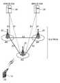
도 1은 무선 통신 시스템을 나타낸 블록도이다. 이는 E-UMTS(Evolved- Universal Mobile Telecommunications System)의 망 구조일 수 있다. E-UMTS 시스템은 LTE(Long Term Evolution) 시스템이라고 할 수도 있다. 무선 통신 시스템은 음성, 패킷 데이터 등과 같은 다양한 통신 서비스를 제공하기 위해 널리 배치된다.1 is a block diagram illustrating a wireless communication system. This may be a network structure of an Evolved-Universal Mobile Telecommunications System (E-UMTS). The E-UMTS system may be referred to as a Long Term Evolution (LTE) system. Wireless communication systems are widely deployed to provide various communication services such as voice, packet data, and the like.
도 1을 참조하면, E-UTRAN(Evolved-UMTS Terrestrial Radio Access Network)은 제어 평면(control plane)과 사용자 평면(user plane)을 제공하는 기지국(20; Base Station, BS)을 포함한다.Referring to FIG. 1, an Evolved-UMTS Terrestrial Radio Access Network (E-UTRAN) includes a base station (BS) 20 that provides a control plane and a user plane.
단말(10; User Equipment, UE)은 고정되거나 이동성을 가질 수 있으며, MS(Mobile station), UT(User Terminal), SS(Subscriber Station), 무선기기(Wireless Device) 등 다른 용어로 불릴 수 있다. 기지국(20)은 일반적으로 단 말(10)과 통신하는 고정된 지점(fixed station)을 말하며, eNB(evolved-NodeB), BTS(Base Transceiver System), 액세스 포인트(Access Point) 등 다른 용어로 불릴 수 있다. 하나의 기지국(20)은 적어도 하나의 셀에 대해 서비스를 제공할 수 있다. 셀은 기지국(20)이 통신 서비스를 제공하는 영역이다. 기지국(20) 간에는 사용자 트래픽 혹은 제어 트래픽 전송을 위한 인터페이스가 사용될 수도 있다. 이하에서 하향링크(downlink)는 기지국(20)에서 단말(10)로의 통신을 의미하며, 상향링크(uplink)는 단말(10)에서 기지국(20)으로의 통신을 의미한다.The UE 10 may be fixed or mobile and may be called by other terms such as a mobile station (MS), a user terminal (UT), a subscriber station (SS), a wireless device, and the like. The
기지국(20)들은 X2 인터페이스를 통하여 서로 연결될 수 있다. 기지국(20)은 S1 인터페이스를 통해 EPC(Evolved Packet Core), 보다 상세하게는 MME(Mobility Management Entity)/S-GW(Serving Gateway, 30)와 연결된다. S1 인터페이스는 기지국(20)과 MME/S-GW(30) 간에 다수-대-다수 관계(many-to-many-relation)를 지원한다.The
무선 통신 시스템은 셀룰러(cellular) 시스템으로, 단말이 속한 셀에 인접하는 다른 셀이 존재한다. 단말이 속한 셀을 서빙 셀(Serving Cell)이라 하고, 인접하는 다른 셀을 인접 셀(Neighbor Cell)이라 한다.The wireless communication system is a cellular system, and there are other cells adjacent to the cell to which the terminal belongs. The cell to which the UE belongs is called a serving cell, and another adjacent cell is called a neighbor cell.
단말과 네트워크 사이의 무선 인터페이스 프로토콜(radio interface protocol)의 계층들은 통신시스템에서 널리 알려진 개방형 시스템 간 상호접속 (Open System Interconnection, OSI) 모델의 하위 3개 계층을 바탕으로 제1 계층(L1), 제2 계층(L2), 제3 계층(L3)으로 구분될 수 있다. 제1 계층은 물리계층(PHY(physical) layer)이다. 제2 계층은 MAC(Medium Access Control) 계층, RLC(Radio Link Control) 계층 및 PCDP(Packet Data Convergence Protocol) 계층으로 분리될 수 있다. 제3 계층은 RRC(Radio Resource Control) 계층이다.Layers of the radio interface protocol between the terminal and the network are based on the lower three layers of the Open System Interconnection (OSI) model, which is well known in communication systems. It may be divided into a second layer L2 and a third layer L3. The first layer is a physical layer (PHY) layer. The second layer may be divided into a medium access control (MAC) layer, a radio link control (RLC) layer, and a packet data convergence protocol (PCDP) layer. The third layer is a Radio Resource Control (RRC) layer.
도 2는 사용자 평면(user plane)에 대한 무선 프로토콜 구조(radio protocol architecture)를 나타낸 블록도이다. 도 3은 제어 평면(control plane)에 대한 무선 프로토콜 구조를 나타낸 블록도이다. 이는 단말과 E-UTRAN 사이의 무선 인터페이스 프로토콜의 구조를 나타낸다. 사용자 평면은 사용자 데이터 전송을 위한 프로토콜 스택(protocol stack)이고, 제어 평면은 제어신호 전송을 위한 프로토콜 스택이다.FIG. 2 is a block diagram illustrating a radio protocol architecture for a user plane. 3 is a block diagram illustrating a radio protocol structure for a control plane. This shows the structure of the air interface protocol between the terminal and the E-UTRAN. The user plane is a protocol stack for user data transmission, and the control plane is a protocol stack for control signal transmission.
도 2 및 3을 참조하면, 서로 다른 물리계층 사이, 즉 송신 측과 수신 측의 물리계층 사이는 물리채널을 통해 데이터가 이동한다. 물리계층은 상위에 있는 MAC 계층과 전송채널(transport channel)을 통해 연결되어 있다. 전송채널을 통해 MAC 계층과 물리계층 사이의 데이터가 이동한다. 물리계층은 전송채널을 이용하여 MAC 계층 및 상위 계층에게 정보 전송 서비스(information transfer service)를 제공한다.2 and 3, data is moved through physical channels between different physical layers, that is, between physical layers of a transmitting side and a receiving side. The physical layer is connected to the upper MAC layer through a transport channel. Data is transferred between the MAC layer and the physical layer through a transport channel. The physical layer provides an information transfer service to a MAC layer and a higher layer using a transport channel.
MAC 계층은 논리채널(logical channel)을 통해 상위 계층인 RLC 계층에게 서비스를 제공한다. RLC 계층은 신뢰성 있는 데이터의 전송을 지원한다. PDCP 계층은 IP 패킷 헤더 사이즈를 줄여주는 헤더 압축(header compression) 기능을 수행한다.The MAC layer provides a service to an RLC layer, which is a higher layer, through a logical channel. The RLC layer supports the transmission of reliable data. The PDCP layer performs a header compression function that reduces the IP packet header size.
RRC 계층은 제어 평면에서만 정의된다. RRC 계층은 단말과 네트워크 간에 무선 자원을 제어하는 역할을 수행한다. 이를 위해 RRC 계층은 단말과 네트워크 간에 RRC 메시지를 서로 교환한다. RRC 계층은 무선 베어러(Radio Bearer, 이하 RB)들의 설정(configuration), 재설정(re-configuration) 및 해제(release)와 관련되어 논리채널, 전송채널 및 물리채널들의 제어를 담당한다. RB는 단말과 E-UTRAN 간의 데이터 전달을 위해 제2 계층에 의해 제공되는 서비스를 의미한다. 단말의 RRC와 네트워크의 RRC 사이에 RRC 연결(RRC Connection)이 있을 경우, 단말은 RRC 연결 모드(RRC Connected Mode)에 있게 되고, 그렇지 못할 경우 RRC 아이들 모드(RRC Idle Mode)에 있게 된다.The RRC layer is defined only in the control plane. The RRC layer serves to control radio resources between the terminal and the network. To this end, the RRC layer exchanges RRC messages between the UE and the network. The RRC layer is responsible for controlling logical channels, transport channels, and physical channels in connection with configuration, re-configuration, and release of radio bearers (hereinafter, RBs). RB means a service provided by the second layer for data transmission between the UE and the E-UTRAN. If there is an RRC connection (RRC Connection) between the RRC of the terminal and the RRC of the network, the terminal is in the RRC Connected Mode, otherwise it is in the RRC Idle Mode.
RRC 계층 상위에 위치하는 NAS(Non-Access Stratum) 계층은 연결 관리(Session Management)와 이동성 관리(Mobility Management) 등의 기능을 수행한다.The non-access stratum (NAS) layer located above the RRC layer performs functions such as session management and mobility management.
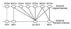
도 4는 하향링크 논리채널과 하향링크 전송채널 간의 맵핑(mapping)을 나타낸다. 이는 3GPP TS 36.300 V8.3.0 (2007-12) Technical Specification Group Radio Access Network; Evolved Universal Terrestrial Radio Access (E-UTRA) and Evolved Universal Terrestrial Radio Access Network (E-UTRAN); Overall description; Stage 2 (Release 8)의 6.1.3.2절을 참조할 수 있다.4 shows mapping between a downlink logical channel and a downlink transport channel. This includes 3GPP TS 36.300 V8.3.0 (2007-12) Technical Specification Group Radio Access Network; Evolved Universal Terrestrial Radio Access (E-UTRA) and Evolved Universal Terrestrial Radio Access Network (E-UTRAN); Overall description; See section 6.1.3.2 of Stage 2 (Release 8).
도 4를 참조하면, PCCH(Paging Control Channel)는 PCH(Paging Channel)에 맵핑되고, BCCH(Broadcast Control Channel)은 BCH(Broadcast Channel) 또는 DL-SCH(Downlink Shared Channel)에 맵핑된다. CCCH(Common Control Channel), DCCH(Dedicated Control Channel), DTCH(Dedicated Traffic Channel), MCCH(Multicast Control Channel) 및 MTCH(Multicast Traffic Channel)는 DL-SCH에 맵핑된다. MCCH와 MTCH는 MCH(Multicast Channel)에도 맵핑된다.Referring to FIG. 4, a paging control channel (PCCH) is mapped to a paging channel (PCH), and a broadcast control channel (BCCH) is mapped to a broadcast channel (BCH) or a downlink shared channel (DL-SCH). Common Control Channel (CCCH), Dedicated Control Channel (DCCH), Dedicated Traffic Channel (DTCH), Multicast Control Channel (MCCH) and Multicast Traffic Channel (MTCH) are mapped to DL-SCH. MCCH and MTCH are also mapped to MCH (Multicast Channel).
각 논리채널 타입은 어떤 종류의 정보가 전송되는가에 따라 정의된다. 논리채널은 제어채널과 트래픽 채널 2종류가 있다.Each logical channel type is defined by what kind of information is transmitted. There are two types of logical channels: control channels and traffic channels.
제어채널은 제어 평면 정보의 전송에 사용된다. BCCH는 시스템 제어정보를 브로드캐스팅하기 위한 하향링크 채널이다. PCCH는 페이징 정보를 전송하는 하향링크 채널로, 네트워크가 단말의 위치를 모를 때 사용한다. CCCH는 단말과 네트워크 간의 제어정보를 전송하는 채널로, 단말이 네트워크와 RRC 연결이 없을 때 사용한다. MCCH는 MBMS(Multimedia Broadcast Multicast Service) 제어정보를 전송하는 데 사용되는 점대다(point-to-multipoint) 하향링크 채널이며, MBMS를 수신하는 단말들에게 사용된다. DCCH는 단말과 네트워크 간의 전용 제어정보를 전송하는 점대점 양방향 채널이며, RRC 연결을 갖는 단말에 의해 사용된다.The control channel is used for transmission of control plane information. BCCH is a downlink channel for broadcasting system control information. PCCH is a downlink channel that transmits paging information and is used when the network does not know the location of the terminal. CCCH is a channel for transmitting control information between the terminal and the network, and is used when the terminal does not have an RRC connection with the network. The MCCH is a point-to-multipoint downlink channel used to transmit multimedia broadcast multicast service (MBMS) control information, and is used for terminals receiving MBMS. DCCH is a point-to-point bidirectional channel for transmitting dedicated control information between a terminal and a network, and is used by a terminal having an RRC connection.
트래픽 채널은 사용자 평면 정보의 전송에 사용된다. DTCH는 사용자 정보의 전송을 위한 점대점 채널이며, 상향링크와 하향링크 모두에 존재한다. MTCH는 트래픽 데이터의 전송을 위한 점대다 하향링크 채널이며, MBMS를 수신하는 단말에게 사용된다.The traffic channel is used for transmission of user plane information. DTCH is a point-to-point channel for transmitting user information and exists in both uplink and downlink. MTCH is a point-to-many downlink channel for transmission of traffic data, and is used for a terminal receiving an MBMS.
전송채널은 무선 인터페이스를 통해 데이터가 어떻게 어떤 특징으로 전송되는가에 따라 분류된다. BCH는 셀 전 영역에서 브로드캐스트되고 고정된 미리 정의된 전송 포맷을 가진다. DL-SCH는 HARQ(Hybrid Automatic Repeat reQuest)의 지원, 변조, 코딩 및 전송파워의 변화에 의한 동적 링크 적응의 지원, 브로드캐스트의 가능성, 빔포밍의 가능성, 동적/반정적(semi-static) 자원 할당 지원, 단말 파워 절약을 위한 DRX(Discontinuous Reception) 지원 및 MBMS 전송 지원으로 특징된다. PCH는 단말 파워 절약을 위한 DRX 지원, 셀 전 영역에의 브로드캐스트로 특징된다. MCH는 셀 전 영역에의 브로드캐스트 및 MBSFN(MBMS Single Frequency Network) 지원으로 특징된다.Transport channels are classified according to how and with what characteristics data is transmitted over the air interface. The BCH has a predefined transmission format that is broadcast and fixed in the entire cell area. DL-SCH supports HARQ (Hybrid Automatic Repeat reQuest), support for dynamic link adaptation by changing modulation, coding and transmission power, possibility of broadcast, possibility of beamforming, and dynamic / semi-static resources. It is characterized by support for allocation, support for DRX (Discontinuous Reception) for MB power saving, and support for MBMS transmission. PCH is characterized by DRX support for terminal power saving and broadcast to the entire cell area. The MCH is characterized by broadcast to the entire cell area and MBMSN (MBMS Single Frequency Network) support.
도 5는 하향링크 전송채널과 하향링크 물리채널 간의 맵핑을 나타낸다. 이는 3GPP TS 36.300 V8.3.0 (2007-12)의 5.3.1절을 참조할 수 있다.5 shows a mapping between a downlink transport channel and a downlink physical channel. This may be referred to Section 5.3.1 of 3GPP TS 36.300 V8.3.0 (2007-12).
도 5를 참조하면, BCH는 PBCH(Physical Broadcast Channel)에 맵핑되고, MCH는 PMCH(Physical Multicast Channel)에 맵핑되고, PCH와 DL-SCH는 PDSCH(Physical Downlink Shared Channel)에 맵핑된다. PBCH는 BCH 전송 블록(transport block)을 나르고, PMCH는 MCH를 나르고, PDSCH는 DL-SCH와 PCH를 나른다.Referring to FIG. 5, a BCH is mapped to a physical broadcast channel (PBCH), an MCH is mapped to a physical multicast channel (PMCH), and a PCH and a DL-SCH are mapped to a physical downlink shared channel (PDSCH). PBCH carries a BCH transport block, PMCH carries an MCH, and PDSCH carries a DL-SCH and a PCH.
물리계층에서 사용되는 몇몇 하향링크 물리 제어채널들이 있다. PDCCH(Physical Downlink Control Channel)는 단말에게 PCH와 DL-SCH의 자원 할당 및 DL-SCH와 관련된 HARQ 정보에 대해 알려준다. PDCCH는 단말에게 상향링크 전송의 자원 할당을 알려주는 상향링크 스케줄링 그랜트를 나를 수 있다. PCFICH(Physical Control Format Indicator Channel)는 단말에게 서브프레임 내에서 PDCCH들의 전송에 사용되는 OFDM(Orthogonal Frequency Division Multiplexing) 심벌의 수를 알려준다. PCFICH는 서브프레임마다 전송된다. PHICH(Physical Hybrid ARQ Indicator Channel)는 상향링크 전송의 응답으로 HARQ ACK/NAK 신호를 나른다.There are several downlink physical control channels used in the physical layer. The Physical Downlink Control Channel (PDCCH) informs the UE about resource allocation of the PCH and DL-SCH and HARQ information related to the DL-SCH. The PDCCH may carry an uplink scheduling grant informing the UE of resource allocation of uplink transmission. The Physical Control Format Indicator Channel (PCFICH) informs the UE of the number of Orthogonal Frequency Division Multiplexing (OFDM) symbols used for transmission of PDCCHs in a subframe. PCFICH is transmitted every subframe. The Physical Hybrid ARQ Indicator Channel (PHICH) carries HARQ ACK / NAK signals in response to uplink transmission.
도 6은 무선 프레임의 구조를 나타낸다.6 shows the structure of a radio frame.
도 6을 참조하면, 무선 프레임(Radio Frame)은 10개의 서브프레임(Subframe)으로 구성되고, 하나의 서브프레임은 2개의 슬롯(Slot)으로 구성된다. 무선 프레임 내 슬롯은 0번부터 19번까지 슬롯 번호가 매겨진다. 하나의 서브프레임이 전송되는 데 걸리는 시간을 TTI(transmission time interval)라 한다. TTI는 데이터 전송을 위한 스케줄링 단위라 할 수 있다. 예를 들어, 하나의 무선 프레임의 길이는 10ms이고, 하나의 서브프레임의 길이는 1ms이고, 하나의 슬롯의 길이는 0.5ms 일 수 있다.Referring to FIG. 6, a radio frame includes 10 subframes and one subframe includes two slots. Slots in a radio frame are numbered
무선 프레임의 구조는 예시에 불과하고, 무선 프레임에 포함되는 서브프레임의 수 또는 서브프레임에 포함되는 슬롯의 수는 다양하게 변경될 수 있다.The structure of the radio frame is only an example, and the number of subframes included in the radio frame or the number of slots included in the subframe may be variously changed.
도 7은 하나의 하향링크 슬롯에 대한 자원 그리드(resource grid)를 나타낸 예시도이다.7 is an exemplary diagram illustrating a resource grid for one downlink slot.
도 7을 참조하면, 하향링크 슬롯은 시간 영역(time domain)에서 복수의 OFDM 심벌을 포함하고, 주파수 영역(frequency domain)에서 NDL 자원블록(Resource Block, RB)을 포함한다. 하향링크 슬롯에 포함되는 자원블록의 수 NDL은 셀에서 설정되는 하향링크 전송 대역폭(bandwidth)에 종속한다. 예를 들어, LTE 시스템에서 NDL은 60 내지 110 중 어느 하나일 수 있다. 하나의 자원블록은 주파수 영역에서 복수의 부반송파를 포함한다.Referring to FIG. 7, a downlink slot includes a plurality of OFDM symbols in a time domain and NDL resource blocks (RBs) in a frequency domain. The number NDL of resource blocks included in the downlink slot depends on the downlink transmission bandwidth set in the cell. For example, in the LTE system, NDL may be any one of 60 to 110. One resource block includes a plurality of subcarriers in the frequency domain.
자원 그리드 상의 각 요소(element)를 자원요소(Resource Element)라 한다. 자원 그리드 상의 자원요소는 슬롯 내 인덱스 쌍(pair) (k, ℓ)에 의해 식별될 수 있다. 여기서, k(k=0,...,NDL×12-1)는 주파수 영역 내 부반송파 인덱스이고, ℓ(ℓ =0,...,6)은 시간 영역 내 OFDM 심벌 인덱스이다.Each element on the resource grid is called a resource element. Resource elements on the resource grid may be identified by an index pair (k, l) in the slot. Where k (k = 0, ..., NDL × 12-1) is the subcarrier index in the frequency domain, and l (l = 0, ..., 6) is the OFDM symbol index in the time domain.
여기서, 하나의 자원블록은 시간 영역에서 7 OFDM 심벌, 주파수 영역에서 12 부반송파로 구성되는 7×12 자원요소를 포함하는 것을 예시적으로 기술하나, 자원블록 내 OFDM 심벌의 수와 부반송파의 수는 이에 제한되는 것은 아니다. OFDM 심벌의 수와 부반송파의 수는 사이클릭 프리픽스(Cyclic Prefix, 이하 CP)의 길이, 주파수 간격(frequency spacing) 등에 따라 다양하게 변경될 수 있다. 예를 들어, 노멀(normal) CP의 경우 OFDM 심벌의 수는 7이고, 확장된(extended) CP의 경우 OFDM 심벌의 수는 6이다. 하나의 OFDM 심벌에서 부반송파의 수는 128, 256, 512, 1024, 1536 및 2048 중 하나를 선정하여 사용할 수 있다.Here, an example of one resource block includes 7 × 12 resource elements including 7 OFDM symbols in the time domain and 12 subcarriers in the frequency domain, but the number of OFDM symbols and the number of subcarriers in the resource block is equal to this. It is not limited. The number of OFDM symbols and the number of subcarriers may be variously changed according to the length of a cyclic prefix (CP), frequency spacing, and the like. For example, the number of OFDM symbols is 7 for a normal CP and the number of OFDM symbols is 6 for an extended CP. The number of subcarriers in one OFDM symbol may be selected and used among 128, 256, 512, 1024, 1536 and 2048.
도 8은 서브프레임의 구조를 나타낸다.8 shows a structure of a subframe.
도 8을 참조하면, 서브프레임은 2개의 연속적인(consecutive) 슬롯을 포함한다. 서브프레임 내의 첫 번째 슬롯의 앞선 최대 3 OFDM 심벌들이 PDCCH가 할당되는 제어영역(control region)이고, 나머지 OFDM 심벌들은 PDSCH가 할당되는 데이터영역(data region)이 된다. 제어영역에는 PDCCH 이외에도 PCFICH, PHICH 등의 제어채널이 할당될 수 있다. 단말은 PDCCH를 통해 전송되는 제어정보를 디코딩하여 PDSCH를 통해 전송되는 데이터 정보를 읽을 수 있다. 여기서, 제어영역이 3 OFDM 심벌을 포함하는 것은 예시에 불과하다. 서브프레임 내 제어영역이 포함하는 OFDM 심벌의 수는 PCFICH를 통해 알 수 있다.Referring to FIG. 8, a subframe includes two consecutive slots. The maximum 3 OFDM symbols of the first slot in the subframe are the control region to which the PDCCH is allocated, and the remaining OFDM symbols are the data region to which the PDSCH is allocated. In addition to the PDCCH, the control region may be allocated a control channel such as PCFICH and PHICH. The UE may read the data information transmitted through the PDSCH by decoding the control information transmitted through the PDCCH. Here, it is merely an example that the control region includes 3 OFDM symbols. The number of OFDM symbols included in the control region in the subframe can be known through the PCFICH.
도 9는 기지국이 하나의 안테나를 사용하는 경우, 참조신호(Reference Signal, RS) 구조의 예를 나타낸다.9 illustrates an example of a structure of a reference signal (RS) when a base station uses one antenna.
도 9를 참조하면, R0는 0번 안테나를 통한 참조신호 전송에 사용되는 자원요소를 나타낸다. 하나의 OFDM 심벌에서 R0는 6 부반송파 간격으로 위치한다. 자원블록 내 R0의 수는 일정하다.Referring to FIG. 9, R0 represents a resource element used for transmitting a reference signal through
이하, 참조신호 전송에 사용되는 자원요소를 참조심벌이라 한다. 참조심벌을 제외한 자원요소는 데이터 전송에 사용될 수 있다. 데이터 전송에 사용되는 자원요소를 데이터 심벌이라 한다. 안테나마다 하나의 참조신호가 전송된다. 각 안테나별 참조신호는 참조심벌들로 구성된다.Hereinafter, a resource element used for transmitting a reference signal is referred to as a reference symbol. Resource elements other than reference symbols may be used for data transmission. Resource elements used for data transmission are called data symbols. One reference signal is transmitted for each antenna. The reference signal for each antenna is composed of reference symbols.
그런데, 서빙 셀과 인접 셀이 사용하는 참조신호가 동일한 구조일 경우, 셀 간 참조신호 충돌이 발생할 수 있다. 이를 방지하기 위해, 참조심벌을 주파수 영역에서 부반송파 단위로 천이(shift)하거나, 시간 영역에서 OFDM 심벌 단위로 천이하여 참조신호를 보호할 수 있다.However, if the reference signals used by the serving cell and the adjacent cell have the same structure, a reference signal collision between cells may occur. In order to prevent this, the reference symbols may be shifted by the subcarriers in the frequency domain or by the OFDM symbols in the time domain to protect the reference signals.
도 10은 기지국이 하나의 안테나를 사용하는 경우, 주파수 영역에서 천이된 참조신호의 예를 나타낸다.10 shows an example of a reference signal that is transitioned in the frequency domain when the base station uses one antenna.
도 10을 참조하면, 제1 셀은 하나의 OFDM 심벌에서 6 부반송파 간격으로 위치한 참조심벌을 사용한다. 따라서, 주파수 영역에서 부반송파 단위의 천이를 통하여, 적어도 5개의 인접 셀(제2 셀 내지 제6 셀)은 각각 다른 자원요소에 위치한 참조심벌을 사용할 수 있다. 따라서, 제1 셀 내지 제6 셀 간 참조신호 충돌을 피할 수 있다. 예를 들어, 주파수 영역에서 참조심벌을 천이시킬 부반송파의 수를 나타내는 변수(variable)를 vshift라 할 경우, vshift는 다음 수학식과 같이 나타낼 수 있 다.Referring to FIG. 10, the first cell uses reference symbols located at 6 subcarrier intervals in one OFDM symbol. Accordingly, at least five neighboring cells (second to sixth cells) may use reference symbols located in different resource elements through the transition of the subcarrier unit in the frequency domain. Thus, reference signal collision between the first and sixth cells can be avoided. For example, if a variable (variable) representing the number of sub-carriers to shift the reference symbol in the frequency domain,shift d v, v is theshift it can be expressed as the following mathematical expression.

여기서, Ncell_ID는 셀 ID(identity)를 나타낸다.Here, Ncell_ID indicates a cell ID.
참조신호에 미리 정의된 참조신호 시퀀스를 곱하여 전송할 수 있다. 예를 들어, 참조신호 시퀀스는 PN(Pseudo-random) 시퀀스, m-시퀀스 등을 이용할 수 있다. 참조신호 시퀀스는 이진(binary) 시퀀스 또는 복소(complex) 시퀀스를 사용할 수 있다. 기지국이 참조신호 시퀀스를 곱해 전송할 경우, 단말은 인접 셀로부터 수신되는 참조신호의 간섭을 감소시켜 채널추정 성능을 향상시킬 수 있다. 참조신호 시퀀스는 하나의 서브프레임 내 OFDM 심벌 단위로 적용될 수 있다. 참조신호 시퀀스는 셀 ID, 하나의 무선 프레임 내 슬롯 번호, 슬롯 내 OFDM 심벌 인덱스, CP의 종류 등에 따라 달라질 수 있다.A reference signal may be transmitted by multiplying a predefined reference signal sequence. For example, the reference signal sequence may use a pseudo-random (PN) sequence, an m-sequence, or the like. The reference signal sequence may use a binary sequence or a complex sequence. When the base station multiplies and transmits the reference signal sequence, the terminal can improve the channel estimation performance by reducing the interference of the reference signal received from the adjacent cell. The reference signal sequence may be applied in units of OFDM symbols in one subframe. The reference signal sequence may vary according to a cell ID, a slot number in one radio frame, an OFDM symbol index in a slot, a type of CP, and the like.
도 9를 참조하면, 참조심벌을 포함하는 OFDM 심벌에서 각 안테나별 참조심벌의 개수는 2개이다. 서브프레임은 주파수 영역에서 NDL 자원블록을 포함하므로, 하나의 OFDM 심벌에서 각 안테나별 참조심벌의 개수는 2×NDL이다. 따라서, 참조신호 시퀀스의 길이는 2×NDL이다.Referring to FIG. 9, the number of reference symbols for each antenna in the OFDM symbol including the reference symbols is two. Since the subframe includes NDL resource blocks in the frequency domain, the number of reference symbols for each antenna in one OFDM symbol is 2 × NDL . Therefore, the length of the reference signal sequence is 2 x NDL .
다음 수학식은 참조신호 시퀀스 r(m)이라 할 때, r(m)으로 사용되는 복수 시퀀스의 일 예를 나타낸다.The following equation shows an example of a plurality of sequences used as r (m) when the reference signal sequence r (m).

여기서, m은 0,1,...,2Nmax,DL-1이다. Nmax,DL은 최대 대역폭에 해당하는 자원블록의 개수이다. 예를 들어, LTE 시스템에서 Nmax,DL은 110이다. c(i)는 PN 시퀀스로 길이-31의 골드(Gold) 시퀀스에 의해 정의될 수 있다. 다음 수학식은 2×Nmax,DL길이 시퀀스 c(i)의 일 예를 나타낸다.Where m is 0,1, ..., 2Nmax, DL -1. Nmax, DL is the number of resource blocks corresponding to the maximum bandwidth. For example, Nmax, DL is 110 in an LTE system. c (i) may be defined by a Gold sequence of length-31 as a PN sequence. The following equation shows an example of a 2 × Nmax, DL length sequence c (i).

여기서, NC=1600이고, x1(i)은 제1 m-시퀀스이고, x2(i)는 제2 m-시퀀스이다. 예를 들어, 제1 m-시퀀스 또는 제2 m-시퀀스는 매 OFDM 심벌마다 셀 ID, 하나의 무선 프레임 내 슬롯 번호, 슬롯 내 OFDM 심벌 인덱스, CP의 종류 등에 따라 초기화(initialization)될 수 있다.Wherein NC = 1600, x1 (i) is the first m-sequence and x2 (i) is the second m-sequence. For example, the first m-sequence or the second m-sequence may be initialized for each OFDM symbol according to a cell ID, a slot number in one radio frame, an OFDM symbol index in a slot, a type of CP, and the like.
Nmax,DL보다 작은 대역폭을 갖는 시스템의 경우, 2×Nmax,DL길이로 생성된 참조신호 시퀀스의 일정 부분만을 선택해서 사용할 수 있다.In the case of Nmax, the system has a smaller bandwidth than theDL, it can be used to select only a portion of the reference signal sequence generated by 2 × Nmax, DL length.
기지국이 복수의 안테나를 사용하는 다중 안테나 전송의 경우, 안테나마다 하나의 자원 그리드가 있다. 이하에서 설명할 도 11 및 12에서는 편의를 위해 동일한 자원 그리드 상에 모든 안테나에 대한 참조심벌을 나타낸다. Rp는 p번 안테나를 통한 참조신호 전송에 사용되는 자원요소를 나타낸다(p∈{0, 1, 2, 3}). Rp는 p번 안테나를 제외한 다른 안테나를 통해서는 어떤 전송에도 사용되지 않는다. 안테나 간 간섭을 주지 않기 위해서이다.In the case of multi-antenna transmission in which a base station uses a plurality of antennas, there is one resource grid for each antenna. 11 and 12 to be described below show reference symbols for all antennas on the same resource grid for convenience. Rp denotes a resource element used for transmitting a reference signal through antenna p (p ∈ {0, 1, 2, 3}). Rp is not used for any transmission through any antenna other than antenna p. This is to avoid interference between antennas.
도 11은 기지국이 2개의 안테나를 사용하는 경우, 서브프레임에 맵핑되는 참조신호의 예를 나타낸다.11 shows an example of a reference signal mapped to a subframe when the base station uses two antennas.
도 11을 참조하면, R0 및 R1은 서로 중복되지 않는다. 하나의 OFDM 심벌에서 각 Rp는 6 부반송파 간격으로 위치한다. 서브프레임 내 R0의 수와 R1의 수는 하다. 또한, 동일한 개수의 R0와 R1이 동일한 OFDM 심벌에 포함된다.Referring to FIG. 11, R0 and R1 do not overlap each other. Each Rp in one OFDM symbol is located at 6 subcarrier intervals. The number of R0 and the number of R1 in the subframe is the same. In addition, the same number of R0 and R1 are included in the same OFDM symbol.
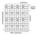
도 12는 기지국이 4개의 안테나를 사용하는 경우, 참조신호 구조의 예를 나타낸다.12 shows an example of a reference signal structure when the base station uses four antennas.
도 12를 참조하면, R0 내지 R3는 서로 중복되지 않는다. 하나의 OFDM 심벌에서 각 Rp는 6 부반송파 간격으로 위치한다. 서브프레임 내 R0의 수와 R1의 수는 동일하고, R2의 수와 R3의 수는 동일하다. 서브프레임 내 R2, R3의 수는 R0, R1의 수보다 적다.12, R0 to R3 do not overlap each other. Each Rp in one OFDM symbol is located at 6 subcarrier intervals. The number of R0 and the number of R1 in the subframe is the same, the number of R2 and the number of R3 is the same. The number of R2 and R3 in the subframe is less than the number of R0 and R1.
R0와 R1이 페어링(pairing)되고, R2와 R3가 페어링되어 각기 다른 OFDM 심벌에 포함된다. 따라서, 0번 안테나 및 1번 안테나의 참조신호가 페어링되어 동일한 OFDM 심벌에 전송된다. 예를 들어, 서브프레임 내 첫 번째 슬롯과 두 번째 슬롯 모두 OFDM 심벌 인덱스가 0, 4(ℓ=0, 4)인 OFDM 심벌에 0번 안테나 및 1번 안테나의 참조신호가 페어링되어 전송된다. 또, 2번 안테나 및 3번 안테나의 참조신호가 페어링되어 동일한 OFDM 심벌에 전송된다. 예를 들어, 서브프레임 내 첫 번째 슬롯과 두 번째 슬롯 모두 OFDM 심벌 인덱스가 1(ℓ=1)인 OFDM 심벌에 2번 안테나 및 3번 안테나의 참조신호가 페어링되어 전송된다.R0 and R1 are paired, and R2 and R3 are paired and included in different OFDM symbols. Accordingly, reference signals of
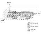
도 13은 OFDM 심벌 인덱스가 0(ℓ=0)인 경우, 자원요소당 전력 할당의 예를 나타낸 그래프이다. x축은 안테나 인덱스이고, y축은 자원블록 내 부반송파 인덱스이고, z축은 전력이다.FIG. 13 is a graph illustrating an example of power allocation per resource element when the OFDM symbol index is 0 (l = 0). The x-axis is the antenna index, the y-axis is the subcarrier index in the resource block, the z-axis is the power.
도 13을 참조하면, 0번 안테나 및 1번 안테나의 경우, 각각 2개의 참조심벌과 4개의 데이터 심벌이 있다. 2번 안테나 및 3번 안테나의 경우, 각각 4개의 데이터 심벌이 있다. OFDM 심벌 인덱스가 4인 경우, 안테나 인덱스를 변경하여 동일한 그래프를 적용할 수 있다.Referring to FIG. 13, in case of
도 14는 OFDM 심벌 인덱스가 1(ℓ=1)인 경우, 자원요소당 전력 할당의 예를 나타낸 그래프이다. x축은 안테나 인덱스이고, y축은 자원블록 내 부반송파 인덱스이고, z축은 전력이다.14 is a graph illustrating an example of power allocation per resource element when the OFDM symbol index is 1 (l = 1). The x-axis is the antenna index, the y-axis is the subcarrier index in the resource block, the z-axis is the power.
도 14를 참조하면, 0번 안테나 및 1번 안테나의 경우, 각각 4개의 데이터 심벌이 있다. 2번 안테나 및 3번 안테나의 경우, 각각 2개의 참조심벌과 4개의 데이터 심벌이 있다.Referring to FIG. 14, in case of
이와 같이, OFDM 심벌 인덱스가 0, 4(ℓ=0, 4)인 경우, 0번 안테나 및 1번 안테나의 페어링된 참조신호가 전송되고, 0번 안테나 및 1번 안테나에 전력이 많이 할당된다. OFDM 심벌 인덱스가 1(ℓ=1)인 경우, 2번 안테나 및 3번 안테나의 페어 링된 참조신호가 전송되고, 2번 안테나 및 3번 안테나에 전력이 많이 할당된다.As such, when the OFDM symbol index is 0 and 4 (L = 0, 4), paired reference signals of
즉, 서로 다른 페어링의 참조신호는 항상 각각 다른 OFDM 심벌을 통해 전송된다. 따라서, 참조심벌의 전력 부스팅(power boosting)이 적용될 때 하나의 OFDM 심벌에서는 특정 페어링에 대한 안테나들의 전력만 높이게 된다. 또, 각 안테나별 균등전력 전송이 어려워진다. 균등전력 전송은 다중 안테나 시스템에서 각 안테나별 송신 전력을 최대한 동일하게 하는 것을 말한다. 다중 안테나의 균등전력 전송은 구현비용을 감소시키고, 시스템 성능을 향상시킬 수 있다. 다중 안테나의 균등전력 전송이 가능하려면, 하나의 OFDM 심벌에서 모든 안테나 각각의 참조심벌의 개수가 동일한 것이 바람직하다.That is, reference signals of different pairings are always transmitted through different OFDM symbols. Therefore, when power boosting of a reference symbol is applied, only one antenna increases power of a specific pairing in one OFDM symbol. Moreover, equal power transmission by each antenna becomes difficult. Uniform power transmission refers to making transmission power of each antenna as same as possible in a multi-antenna system. Equal power transmission of multiple antennas can reduce implementation costs and improve system performance. In order to enable equal power transmission of multiple antennas, it is preferable that the number of reference symbols of each antenna is the same in one OFDM symbol.
하나의 서브프레임 내에서 R0와 R1 페어링이 R2와 R3 페어링보다 시간 영역에서 2배 더 많다. 2번 및 3번 안테나는 0번 및 1번 안테나에 비해 시간 선택적 채널(time selective channel)에서 낮은 채널추정성능을 보인다. 시간 선택적 채널인지 여부는 코히어런트 타임(coherent time)을 이용하여 알 수 있다. 코히어런트 타임은 도플러 확산(Doppler spread)에 반비례한다. 그런데, 각 안테나별 균등전력 전송을 하도록 설계된 다중안테나 기법을 사용하는 경우, 각 안테나별 균등하지 않은 채널추정 성능은 심각한 시스템의 성능을 저하시키는 문제가 있다. 따라서, 다중 안테나 시스템에서 각 안테나별 균등전력 전송을 위한 참조신호 전송 방법을 제공할 필요가 있다.In one subframe, R0 and R1 pairing are twice as many in the time domain as R2 and R3 pairing.
다중 안테나 시스템의 경우, 각 안테나별 참조신호를 구분할 수 있어야 데이터를 복원할 수 있다. 각 안테나별 참조신호 간 간섭을 방지하기 위해, FDM(Frequency Division Multiplexing), TDM(Time Division Multiplexing) 또는 CDM(Code Division Multiplexing) 등이 사용될 수 있다. FDM은 각 안테나별 참조신호가 주파수 영역에서 분리되어 전송되는 것이다. TDM은 각 안테나별 참조신호가 시간 영역에서 분리되어 전송되는 것이다. CDM은 각 안테나별 참조신호에 다른 시퀀스가 사용되어 전송되는 것이다. FDM, TDM을 사용하여 다중 안테나를 통해 참조신호를 전송하는 경우, 각 안테나별 참조심벌은 중복되지 않는다. CDM을 사용하는 경우, 각 안테나별 참조신호 전송에 사용되는 자원요소가 중복될 수 있다. 따라서, CDM을 사용하는 경우, 참조신호 오버헤드를 크게 증가시키지 않으면서도 다중 안테나를 통해 참조신호를 전송할 수 있다.In the case of a multi-antenna system, data can be restored only if reference signals for each antenna can be distinguished. In order to prevent interference between reference signals for each antenna, frequency division multiplexing (FDM), time division multiplexing (TDM), or code division multiplexing (CDM) may be used. In FDM, reference signals for each antenna are transmitted separately in the frequency domain. In TDM, reference signals for each antenna are transmitted separately in the time domain. CDM is transmitted by using a different sequence for each antenna reference signal. When a reference signal is transmitted through multiple antennas using FDM and TDM, reference symbols for each antenna do not overlap. In the case of using the CDM, resource elements used for transmission of reference signals for each antenna may overlap. Therefore, when using the CDM, the reference signal can be transmitted through multiple antennas without greatly increasing the reference signal overhead.
이하, CDM을 사용하여 다중 안테나 시스템에서 각 안테나별 균등전력 전송을 위한 참조신호 전송 방법을 설명한다.Hereinafter, a reference signal transmission method for equal power transmission for each antenna in a multi-antenna system using a CDM will be described.
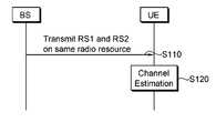
도 15는 다중 안테나 시스템에서 참조신호 전송 방법을 나타낸 흐름도이다.15 is a flowchart illustrating a method of transmitting a reference signal in a multi-antenna system.
도 15를 참조하면, 기지국은 단말로 동일한 무선자원을 사용하여 제1 안테나 그룹을 통해 제1 참조신호(RS1), 제2 안테나 그룹을 통해 제2 참조신호(RS2)를 전송한다(S110). 제1 참조신호는 제1 시퀀스를 사용하고, 제2 참조신호는 제2 시퀀스를 사용한다. 단말은 제1 참조신호와 제2 참조신호를 이용하여 채널을 추정한다(S120).Referring to FIG. 15, the base station transmits a first reference signal RS1 through a first antenna group and a second reference signal RS2 through a second antenna group by using the same radio resource to the terminal (S110). The first reference signal uses a first sequence and the second reference signal uses a second sequence. The terminal estimates a channel using the first reference signal and the second reference signal (S120).
이와 같이 CDM을 사용하면, 하나의 안테나에 대한 참조심벌이 사용되는 자원요소에 다른 안테나의 참조심벌이 다중화(multiplexing)될 수 있다. 하나의 안테나에 대한 제1 참조신호에는 제1 시퀀스가 사용되고, 다른 하나의 안테나에 대한 제2 참조신호에는 상기 제1 시퀀스에 직교(orthogonal)하는 제2 시퀀스가 사용될 수 있다. 제1 시퀀스와 제2 시퀀스가 직교하는 경우, 단말은 제1 시퀀스와 제2 시퀀스를 간섭 없이 복구할 수 있다. 또한, 제2 시퀀스는 제1 시퀀스와 상관도(correlation)가 낮은 시퀀스를 사용할 수도 있다.By using the CDM as described above, reference symbols of another antenna may be multiplexed to resource elements for which reference symbols for one antenna are used. A first sequence may be used for the first reference signal for one antenna, and a second sequence orthogonal to the first sequence may be used for the second reference signal for the other antenna. When the first sequence and the second sequence are orthogonal, the terminal may recover the first sequence and the second sequence without interference. In addition, the second sequence may use a sequence having a low correlation with the first sequence.
예를 들어, 4개의 안테나를 사용하는 경우, 제1 시퀀스를 사용하는 0번 안테나 및 1번 안테나의 참조신호가 페어링된 OFDM 심벌에서 2번 안테나 및 3번 안테나의 참조신호 페어링에 제2 시퀀스를 사용하여 CDM을 적용한다. 이를 통해, 참조심벌을 포함하는 각 OFDM 심벌은 모든 안테나의 참조신호를 동시에 전송할 수 있다. 하나의 OFDM 심벌에서 모든 안테나 각각의 참조심벌의 개수가 동일하므로 균등전력 전송이 가능해진다.For example, when four antennas are used, a second sequence is added to reference signal pairings of
제1 시퀀스와 제2 시퀀스가 서로 직교하면, 제1 시퀀스와 제2 시퀀스로 어떠한 시퀀스도 사용 가능하다. 일반적으로, 참조신호 시퀀스는 랜덤 시퀀스이다. 이하, 제1 시퀀스를 PN(Pseudo-random) 시퀀스라 한다. 예를 들어, 제2 시퀀스는 PN 시퀀스가 시간 영역에서 순환 천이(cyclic shift) 또는 지연(delay)된 것일 수 있다. 시간 영역에서 순환 천이(time-domain circular shift)를 적용하면, 제2 시퀀스는 주파수 영역에서 PN 시퀀스에 위상 천이(phase rotation) 시퀀스를 곱한 형태로 구성된다. 이하, 위상 천이 시퀀스를 OS(orthogonal sequence)라 한다.If the first sequence and the second sequence are orthogonal to each other, any sequence can be used as the first sequence and the second sequence. In general, the reference signal sequence is a random sequence. Hereinafter, the first sequence is called a pseudo-random (PN) sequence. For example, the second sequence may be a cyclic shift or delay in the PN sequence in the time domain. When a time-domain circular shift is applied in the time domain, the second sequence is configured by multiplying a PN sequence by a phase rotation sequence in the frequency domain. Hereinafter, the phase shift sequence is referred to as an orthogonal sequence (OS).
제1 시퀀스는 수학식 4의 참조신호 시퀀스일 수 있다. 참조신호 시퀀스 r(m)에서 순환 천이를 통해 얻어지는 제2 시퀀스를 ri(m)이라 하고, 다음 수학식과 같이 나타낼 수 있다.The first sequence may be a reference signal sequence of

여기서, i=1,2,...,N이다. i에 따라 N개의 제2 시퀀스를 생성할 수 있다. N은 채널 상황에 따라 달라질 수 있다. θi는 순환 천이값으로, θi의 예는 다음 수학식과 같이 나타낼 수 있다.Where i = 1,2, ..., N. According to i, N second sequences may be generated. N may vary depending on channel conditions. θi is a cyclic shift value, and an example of θi can be expressed by the following equation.

θi가 0인 경우, 제2 시퀀스는 제1 시퀀스와 동일하다. 즉, 참조신호에 사용되는 참조신호 시퀀스는 PN 시퀀스에 OS를 곱한 2계층 시퀀스(two-layered sequence)이다. 이하, 'PN+OS'는 PN 시퀀스에 OS를 곱한 참조신호 시퀀스를 의미한다. 예를 들어, 'PN0+OS0'와 'PN0+OS1'은 동일한 PN 시퀀스에 다른 순환천이를 적용한 것으로, 서로 직교한다. 즉, 서로 직교하는 참조신호 시퀀스들은 동일한 PN 시퀀스에 서로 다른 OS들을 곱하여 생성할 수 잇다. PN 시퀀스는 OFDM 심벌 위치에 따라 바뀔 수 있다. 참조신호 시퀀스는 항상 바뀐 PN 시퀀스의 순환 천이된 것이어야 한다.When θi is 0, the second sequence is the same as the first sequence. That is, the reference signal sequence used for the reference signal is a two-layered sequence obtained by multiplying the PN sequence by the OS. Hereinafter, 'PN + OS' means a reference signal sequence obtained by multiplying the PN sequence by the OS. For example, 'PN0 + OS0' and 'PN0 + OS1' apply different cyclic shifts to the same PN sequence and are orthogonal to each other. That is, orthogonal reference signal sequences may be generated by multiplying different OSs by the same PN sequence. The PN sequence may change depending on the OFDM symbol position. The reference signal sequence must always be a cyclic shift of the changed PN sequence.
순환 천이값 θi는 각 안테나에 대한 채널의 임펄스 응답을 구별하기 위해 충분한 간격을 갖고 있어야 한다. 무선 통신 시스템이 실효(effective) OFDM 심벌의 길이가 66.7㎲이고, 5㎲의 최대 지연 스프레드(delay spread)의 채널 환경에서 동작한다고 가정한다. 이 경우, 최소 5㎲ 단위로 순환 천이값을 가져야 한다. 따라서, 12개의 순환 천이를 구별할 수가 있다. 그런데, 하나의 OFDM 심벌에서 참조심벌이 6 부반송파 간격으로 위치할 경우, 가용 순환 천이 개수가 6배 감소한다. 즉, 12/6=2개의 순환 천이값을 가질 수 있다.The cyclic shift value θi must be sufficiently spaced to distinguish the impulse response of the channel for each antenna. Assume that a wireless communication system has an effective OFDM symbol length of 66.7 ms and operates in a channel environment of a maximum delay spread of 5 ms. In this case, the cyclic shift value should be at least 5 ms. Thus, 12 cyclic shifts can be distinguished. However, when a reference symbol is located at 6 subcarrier intervals in one OFDM symbol, the number of available cyclic shifts is reduced by 6 times. That is, 12/6 may have two cyclic shift values.
설명의 편의를 위해, 용어를 정의한다. 이하, Px는 참조신호가 맵핑되는 자원요소를 나타낸다. 하나의 안테나의 참조신호가 P1에 사용되면, 모든 P1에 해당 안테나에 대한 참조신호가 맵핑된다. Rp는 p번 안테나의 참조신호 전송에 사용되는 참조심벌이다. Rp에는 PN 시퀀스에 OS를 곱한(PN+OS) 참조신호 시퀀스가 대응된다.For convenience of explanation, terms are defined. Hereinafter, Px represents a resource element to which a reference signal is mapped. When a reference signal of one antenna is used for P1, reference signals for the corresponding antenna are mapped to all P1. Rp is a reference symbol used for transmitting a reference signal of antenna p. Rp corresponds to the reference signal sequence obtained by multiplying the PN sequence by the OS (PN + OS).
도 16은 참조신호 구조의 일 예를 나타낸다.16 shows an example of a reference signal structure.
도 16을 참조하면, 하나의 OFDM 심벌에 P1과 P2는 페어링되어 있고, 다른 OFDM 심벌에 P3와 P4가 페어링되어 있다. Px(x=0,1,2,3), Rp(p=0,1,2,3) 및 Rp에 대응하는 참조신호 시퀀스는 다양한 형태로 구성될 수 있다.Referring to FIG. 16, P1 and P2 are paired to one OFDM symbol, and P3 and P4 are paired to another OFDM symbol. Reference signal sequences corresponding to Px (x = 0,1,2,3), Rp (p = 0,1,2,3) and Rp may be configured in various forms.
다음 표는 자원요소의 위치(Px), 각 안테나별 참조심벌(Rp) 및 참조신호 시퀀스의 제 1 예를 나타낸다.The following table shows a first example of the position Px, the reference symbol Rp for each antenna, and the reference signal sequence.
P1에서는 0번 안테나의 참조신호만, P2에서는 1번 안테나의 참조신호만, P3에서는 2번 안테나의 참조신호만 그리고 P4에서는 3번 안테나의 참조신호만 전송된다. 이는 CDM이 사용되지 않은 것으로, 도 12의 4개의 안테나를 사용하는 경우의 참조신호 구조와 같은 형태를 가진다.Only the reference signal of
다음 표는 자원요소의 위치(Px), 각 안테나별 참조심벌(Rp) 및 참조신호 시퀀스의 제 2 예를 나타낸다.The following table shows a second example of the position Px, the reference symbol Rp for each antenna, and the reference signal sequence.
각 안테나별로 서로 다른 참조신호 시퀀스가 사용될 수 있다. P1 및 P2(또는 P3 및 P4)가 페어링된 OFDM 심벌에서 P1과 P2(또는 P3와 P4)에는 서로 다른 PN 시퀀스가 사용될 수 있다. P1, P3에서 R0와 R2는 서로 직교하는 참조신호 시퀀스를 사용하여 다중화된다. R0와 R2는 동일한 PN 시퀀스를 사용하고, 서로 다른 OS를 사용한다. P2, P4에서 R1와 R3는 서로 직교하는 참조신호 시퀀스를 사용하여 다중화된다. R1와 R3는 동일한 PN 시퀀스를 사용하고, 서로 다른 OS를 사용한다. 따라서, P1 및 P2(또는 P3 및 P4)가 페어링된 OFDM 심벌에서 모든 안테나 각각의 참조심벌이 동일한 개수로 포함된다. 이는 FDM과 CDM을 이용한 것이다. 이 경우, 안테나별 균등전력 전송이 가능하다.Different reference signal sequences may be used for each antenna. Different PN sequences may be used for P1 and P2 (or P3 and P4) in an OFDM symbol in which P1 and P2 (or P3 and P4) are paired. At P1 and P3, R0 and R2 are multiplexed using reference signal sequences orthogonal to each other. R0 and R2 use the same PN sequence and use different OS. At P2 and P4, R1 and R3 are multiplexed using reference signal sequences orthogonal to each other. R1 and R3 use the same PN sequence and use different OS. Accordingly, reference symbols of each antenna are included in the same number in the OFDM symbol in which P1 and P2 (or P3 and P4) are paired. This is done using FDM and CDM. In this case, equal power transmission for each antenna is possible.
표 2의 방식은 안테나별 균등전력 전송을 만족하는 한도에서 다양하게 변경될 수 있다. 즉, 균등전력 전송을 위해 FDM과 CDM을 이용하여, 안테나의 번호에 상관없이 P1 및 P2(또는 P3 및 P4)가 페어링된 OFDM 심벌에서 모든 안테나 각각의 참조심벌을 동일한 개수로 포함시키면 된다.The scheme of Table 2 can be changed in various ways as long as it satisfies the uniform power transmission for each antenna. That is, by using FDM and CDM for equal power transmission, the same number of reference symbols of each antenna may be included in the OFDM symbol in which P1 and P2 (or P3 and P4) are paired regardless of the number of antennas.
다음 표는 자원요소의 위치(Px), 각 안테나별 참조심벌(Rp) 및 참조신호 시퀀스의 제 3 예를 나타낸다.The following table shows a third example of the position Px, the reference symbol Rp for each antenna, and the reference signal sequence.
P1 및 P2(또는 P3 및 P4)가 페어링된 OFDM 심벌에서 P1과 P2(또는 P3와 P4)에는 동일한 PN 시퀀스가 사용될 수 있다. P1, P3에서 R1과 R3는 서로 직교하는 참조신호 시퀀스를 사용하여 다중화된다. R1과 R3는 동일한 PN 시퀀스를 사용하고, 서로 다른 OS를 사용한다. P2, P4에서 R0와 R2는 서로 직교하는 참조신호 시퀀스를 사용하여 다중화된다. R0와 R2는 동일한 PN 시퀀스를 사용하고, 서로 다른 OS를 사용한다. 따라서, P1 및 P2(또는 P3 및 P4)가 페어링된 OFDM 심벌에서 모든 안테나 각각의 참조심벌이 동일한 개수로 포함된다.The same PN sequence may be used for P1 and P2 (or P3 and P4) in an OFDM symbol in which P1 and P2 (or P3 and P4) are paired. In P1 and P3, R1 and R3 are multiplexed using reference signal sequences orthogonal to each other. R1 and R3 use the same PN sequence and use different OS. At P2 and P4, R0 and R2 are multiplexed using reference signal sequences orthogonal to each other. R0 and R2 use the same PN sequence and use different OS. Accordingly, reference symbols of each antenna are included in the same number in the OFDM symbol in which P1 and P2 (or P3 and P4) are paired.
예를 들어, P1에서 R3에 사용하는 OS1은 순환 천이에 상응하는 π/2의 위상을 가질 수 있다. 이때, 각 OFDM 심벌별로 시작 위상 옵셋(phase offset)을 다르게 하여 순환 천이를 정할 수 있다.For example, OS1 used for R3 at P1 may have a phase of π / 2 corresponding to a cyclic shift. In this case, a cyclic shift may be determined by changing a starting phase offset for each OFDM symbol.
도 17은 순환 천이된 참조신호 구조의 예를 나타낸다.17 shows an example of a cyclically shifted reference signal structure.
도 17을 참조하면, 하나의 OFDM 심벌 내의 순환 천이값 θi는 π/2이다. OFDM 심벌 인덱스가 0(ℓ=0)인 경우, P1의 시작 위상 옵셋은 0이다. OFDM 심벌 인덱스가 4(ℓ=4)인 경우, P1의 시작 위상 옵셋은 π/4이다.Referring to FIG. 17, the cyclic shift value θi in one OFDM symbol is π / 2. If the OFDM symbol index is 0 (l = 0), the starting phase offset of P1 is zero. If the OFDM symbol index is 4 (l = 4), the start phase offset of P1 is [pi] / 4.
다음 표는 자원요소의 위치(Px), 각 안테나별 참조심벌(Rp) 및 참조신호 시퀀스의 제 4 예를 나타낸다.The following table shows a fourth example of the position Px of the resource element, the reference symbol Rp for each antenna, and the reference signal sequence.
P1 및 P2(또는 P3 및 P4)가 페어링된 OFDM 심벌에서 P1과 P2(또는 P3와 P4)에는 서로 다른 PN 시퀀스가 사용될 수 있다. P1, P3에서 R0와 R2는 서로 직교하는 참조신호 시퀀스를 사용하여 다중화된다. P2, P4에서 R1와 R3는 서로 직교하는 참조신호 시퀀스를 사용하여 다중화된다. 따라서, P1 및 P2(또는 P3 및 P4)가 페어링된 OFDM 심벌에서 모든 안테나 각각의 참조심벌이 동일한 개수로 포함된다. 동일한 안테나를 통해 전송되는 참조신호이더라도 OFDM 심벌의 위치가 달라 Px의 x가 다른 경우, 다른 PN 시퀀스가 사용될 수 있다. 이 경우, 다중 셀 환경에서 셀 기반의 시퀀스를 랜덤화하는 효과를 얻을 수 있다.Different PN sequences may be used for P1 and P2 (or P3 and P4) in an OFDM symbol in which P1 and P2 (or P3 and P4) are paired. At P1 and P3, R0 and R2 are multiplexed using reference signal sequences orthogonal to each other. At P2 and P4, R1 and R3 are multiplexed using reference signal sequences orthogonal to each other. Accordingly, reference symbols of each antenna are included in the same number in the OFDM symbol in which P1 and P2 (or P3 and P4) are paired. Even if the reference signal is transmitted through the same antenna, if the position of the OFDM symbol is different and x of Px is different, another PN sequence may be used. In this case, an effect of randomizing a cell-based sequence in a multi-cell environment can be obtained.
CDM을 사용하여 다중 안테나의 참조신호를 다중화하는 경우, 다중화 이전의 전력을 균등하게 분할하여 사용할 수 있다. 하지만, CDM을 사용하지 않는 참조신호 구조를 사용하는 단말의 경우에는, 참조신호의 전력이 반으로 줄기 때문에 채널추정성능이 크게 저하될 수 있다. 따라서, CDM되는 각 안테나별 참조신호의 전력을 제어할 수 있다. 즉, 동일한 자원요소에 다중화되는 PN 시퀀스인 제1 시퀀스와 제1 시퀀스가 시간 영역에서 순환 천이된 제2 시퀀스는 서로 다른 비율의 전력을 가질 수 있다. 예를 들어, 특정 안테나의 채널추정 성능을 강인(robust)하게 하기 위해, 특정 안테나의 전력을 제어할 수 있다. 또, 제1 시퀀스에 순환 천이된 제2 시퀀스를 사용하는 안테나의 참조신호 전력을 상대적으로 작게 설정할 수 있다.When multiplexing reference signals of multiple antennas using a CDM, power before multiplexing may be divided and used evenly. However, in the case of a terminal using a reference signal structure not using the CDM, since the power of the reference signal is cut in half, the channel estimation performance may be greatly reduced. Therefore, the power of the reference signal for each antenna to be CDM can be controlled. That is, the first sequence, which is a PN sequence multiplexed on the same resource element, and the second sequence in which the first sequence is cyclically shifted in the time domain may have different ratios of power. For example, to robust the channel estimation performance of a particular antenna, the power of the particular antenna can be controlled. In addition, the reference signal power of the antenna using the second sequence cyclically shifted to the first sequence can be set relatively small.
P1에서 수신되는 신호는 다음 수학식과 같이 나타낼 수 있다.The signal received at P1 can be expressed as the following equation.

여기서, m은 0,1,...,2Nmax,DL-1이다. h1, h2는 채널 정보이고, α는 전력 제어 팩터(power control factor)이다. 총 송신 전력을 1이이라 하면, α는 0≤α≤1이다. 예를 들어, α=1로 하면, 표 1과 같이 Px마다 하나의 안테나가 맵핑된 것을 의미한다. α=0.5로 하는 경우, CDM되는 제1 시퀀스와 제2 시퀀스의 전력이 동일하다. α를 조정함으로써 각 안테나별 참조신호 시퀀스 전력을 조정할 수가 있다.Where m is 0,1, ..., 2Nmax, DL -1. h1 and h2 are channel information, and α is a power control factor. If the total transmission power is 1, α is 0 ≦ α ≦ 1. For example, when α = 1, it means that one antenna is mapped for each Px as shown in Table 1. When? = 0.5, the power of the first sequence and the second sequence to be CDM is the same. By adjusting α, the reference signal sequence power for each antenna can be adjusted.
지금까지 4개의 안테나를 사용하는 경우의 참조신호 구조를 예로 설명하였으나, CDM을 사용하는 참조신호 전송 방법은 4개 이상의 안테나의 경우에도 적용 가능하다.Although the reference signal structure using four antennas has been described as an example, the reference signal transmission method using the CDM can be applied to the case of four or more antennas.
이하, 8개의 안테나를 사용하는 경우, CDM을 사용하는 참조신호 전송 방법을 설명한다. 이하에서는 설명의 편의를 위해, 제1 시퀀스를 PN1(Pseudo-random sequence 1), 제2 시퀀스를 PN2(Pseudo-random sequence 2)라 한다. 위에서 설명한 바와 같이, PN2는 PN1이 시간 영역에서 순환 천이된 것일 수 있다. 시간 영역에서 순환 천이를 적용하면, PN2는 주파수 영역에서 PN1에 위상 천이 시퀀스를 곱한 형태로 구성된다. Rp는 p번 안테나의 참조심벌을 나타낸다. p는 0, 1, 2, …, 7 중 하나이다.Hereinafter, when eight antennas are used, a reference signal transmission method using a CDM will be described. Hereinafter, for convenience of description, the first sequence is referred to as pseudo-random sequence 1 (PN1) and the second sequence is referred to as pseudo-random sequence 2 (PN2). As described above, PN2 may be one in which PN1 is cyclically shifted in the time domain. When cyclic shift is applied in the time domain, PN2 is configured by multiplying PN1 by a phase shift sequence in the frequency domain. Rp represents a reference symbol of antenna p. p is 0, 1, 2,... , One of seven.
이하에서 설명될 도 18 내지 21에서는, P1에는 R0와 R4가 다중화되고, P2에는 R1과 R5가 다중화되고, P3에는 R2와 R6이 다중화되고, P4에는 R3과 R7이 다중화된다. R0, R1, R2, R3에는 각각 참조신호 시퀀스로 PN1이 사용되고, R4, R5, R6, R7에는 각각 참조신호 시퀀스로 PN2가 사용된다. 이를 다음 표와 같이 나타낼 수 있다.In FIGS. 18 to 21 to be described below, R0 and R4 are multiplexed at P1, R1 and R5 are multiplexed at P2, R2 and R6 are multiplexed at P3, and R3 and R7 are multiplexed at P4. PN1 is used as a reference signal sequence for R0, R1, R2, and R3, and PN2 is used as a reference signal sequence for R4, R5, R6, and R7, respectively. This can be expressed as the following table.
이와 같이, 서로 직교 특성을 만족하는 PN1과 PN2를 이용하여 8개의 안테나 각각의 참조신호를 전송할 수 있다.In this way, the reference signals of the eight antennas can be transmitted using PN1 and PN2 satisfying orthogonal characteristics.
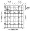
도 18은 CDM을 사용한 참조신호 구조의 제 1 예를 나타낸다.18 shows a first example of a reference signal structure using a CDM.
도 18을 참조하면, 4개의 안테나를 사용하는 참조신호 구조(도 12 참조)가 8개의 안테나를 사용하는 참조신호 구조로 확장된 것이다. 4 내지 7번 안테나 각각의 채널추정 성능은 순서대로 1 내지 4번 안테나 각각의 채널추정 성능과 같다. 참조심벌 오버헤드는 4개의 안테나를 사용하는 참조신호 구조(도 12 참조)와 같은 14%이다. 참조심벌을 포함하는 OFDM 심벌에서 데이터 심벌의 개수가 적절히 유지된다. 따라서, 참조심벌의 전력 부스팅이 용이하다. 특히, 제어영역 내 데이터 심벌 구조가 변경되지 않는다. 따라서, LTE 시스템과 호환 가능하다.Referring to FIG. 18, a reference signal structure using four antennas (see FIG. 12) is extended to a reference signal structure using eight antennas. The channel estimation performance of each of
그런데, 0, 1, 4, 5번 안테나 각각은 2, 3, 6, 7번 안테나 각각에 비해 참조심벌이 2배로 사용된다. 따라서, 2, 3, 6, 7번 안테나는 0, 1, 4, 5번 안테나에 비해 채널추정 성능이 좋지 않다. 특히, 2, 3, 6, 7번 안테나는 시간 선택적 채널에서 채널추정 성능이 열악할 수 있다.However, each of
도 19는 CDM을 사용한 참조신호 구조의 제 2 예를 나타낸다.19 shows a second example of a reference signal structure using a CDM.
도 19를 참조하면, 0 내지 7번 안테나 각각의 참조심벌의 개수가 모두 동일하다. 따라서, 0 내지 7번 안테나 각각의 채널추정 성능은 모두 동일하다. 참조심벌 오버헤드는 19%이다. 또, 하나의 OFDM 심벌에 모든 안테나의 참조심벌이 전송되고, 0 내지 7번 안테나 각각의 참조심벌의 개수가 동일하다. 따라서, 0 내지 7번 안테나 간 균등전력 전송이 가능하다.Referring to FIG. 19, the number of reference symbols of each of
그런데, 참조심벌을 포함하는 OFDM 심벌에서 데이터 심벌의 개수가 적다. 따라서, 참조심벌의 전력 부스팅이 제한된다. 특히, 제어영역 내 참조심벌의 전력 부스팅이 제한되어 제어채널의 신뢰도를 감소시킬 수 있다.However, the number of data symbols in an OFDM symbol including a reference symbol is small. Thus, power boosting of the reference symbol is limited. In particular, power boosting of the reference symbol in the control region is limited, thereby reducing the reliability of the control channel.
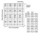
도 20은 CDM을 사용한 참조신호 구조의 제 3 예를 나타낸다.20 shows a third example of a reference signal structure using a CDM.
도 20을 참조하면, 제어영역으로 사용되는 영역에서는 CDM을 사용하지 않고, 4개의 안테나에 대한 참조심벌만 전송된다. 제어영역을 제외한 나머지 영역에서는 CDM을 사용하여 8개 안테나에 대한 참조심벌이 전송될 수 있다. 제어영역 및 제어영역 내 참조신호 구조가 LTE 시스템과 동일하게 유지되어, LTE 시스템과 호환성이 유지된다.Referring to FIG. 20, in the region used as the control region, only reference symbols for four antennas are transmitted without using the CDM. In the other regions except the control region, reference symbols for eight antennas may be transmitted using the CDM. The control area and the reference signal structure in the control area are kept the same as the LTE system, thereby maintaining compatibility with the LTE system.
도 21은 CDM을 사용한 참조신호 구조의 제 4 예를 나타낸다. 이는 도 19의 참조신호 구조의 특성을 유지하면서, 참조심벌 오버헤드를 14%로 감소시킨 참조신호 구조이다.21 shows a fourth example of a reference signal structure using a CDM. This is a reference signal structure in which the reference symbol overhead is reduced to 14% while maintaining the characteristics of the reference signal structure of FIG.
도 21을 참조하면, 0 내지 7번 안테나 각각의 참조심벌의 개수가 모두 동일하다. 따라서, 0 내지 7번 안테나 각각의 채널추정 성능은 모두 동일하다. 참조심벌 오버헤드는 14%이다. 또, 하나의 OFDM 심벌에 모든 안테나의 참조심벌이 전송되고, 0 내지 7번 안테나 각각의 참조심벌의 개수가 동일하다. 따라서, 0 내지 7번 안테나 간 균등전력 전송이 가능하다. 또한, 참조심벌을 포함하는 OFDM 심벌에서 데이터 심벌의 개수가 적절히 유지된다. 따라서, 참조심벌의 전력 부스팅이 용이하다.Referring to FIG. 21, the number of reference symbols of each of
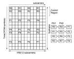
도 22는 CDM을 사용한 참조신호 구조의 제 5 예를 나타낸다.22 shows a fifth example of a reference signal structure using a CDM.
도 22를 참조하면, P1에는 R0와 R4가 다중화되고, P2에는 R1과 R5가 다중화되고, P3에는 R2와 R6이 다중화되고, P4에는 R3과 R7이 다중화된다. 이때, R0, R1, R2, R3에는 각각 참조신호 시퀀스로 PN1이 사용되고, R4, R5, R6, R7에는 각각 참조신호 시퀀스로 PN2가 사용된다. P5에는 PN1이 사용된 R0와 PN2가 사용된 R2가 다중화된다. P6에는 PN1이 사용된 R1과 PN2가 사용된 R3가 다중화된다. P7에는 PN1이 사용된 R2와 PN2가 사용된 R0가 다중화된다. P8에는 PN1이 사용된 R3와 PN2가 사용된 R1이 다중화된다. 이를 다음 표와 같이 나타낼 수 있다.Referring to FIG. 22, R0 and R4 are multiplexed at P1, R1 and R5 are multiplexed at P2, R2 and R6 are multiplexed at P3, and R3 and R7 are multiplexed at P4. At this time, PN1 is used as a reference signal sequence for R0, R1, R2, and R3, and PN2 is used as a reference signal sequence for R4, R5, R6, and R7, respectively. P5 multiplexes R0 with PN1 and R2 with PN2. In P6, R1 using PN1 and R3 using PN2 are multiplexed. In P7, R2 using PN1 and R0 using PN2 are multiplexed. P8 multiplexes R3 using PN1 and R1 using PN2. This can be expressed as the following table.
위 표와 같이, 동일한 안테나를 위한 모든 참조심벌에 동일한 시퀀스를 사용하는 것이 아니라 OFDM 심벌의 위치에 따라 다른 시퀀스를 사용할 수 있다.As shown in the above table, instead of using the same sequence for all reference symbols for the same antenna, different sequences may be used according to the position of the OFDM symbol.
도 23은 다중 안테나를 사용하는 전송기의 예를 나타내는 블록도이다. 전송기는 기지국이거나 단말일 수 있다.23 is a block diagram illustrating an example of a transmitter using multiple antennas. The transmitter may be a base station or a terminal.
도 23을 참조하면, 전송기(100)는 참조신호 생성기(110), 데이터 프로세서(120) 및 MIMO 프로세서(130)를 포함한다.Referring to FIG. 23, the
참조신호 생성기(110)는 지금까지 설명한 바와 같이 참조신호를 생성한다. 데이터 프로세서(120)는 데이터를 처리하여 데이터 심벌을 형성한다. 예를 들어, 데이터 처리에는 채널코딩, 변조(modultion) 등이 있다. MIMO 프로세서(130)는 데이터 심벌과 참조신호를 송신 안테나(190-1, …,190-Nt)에 따른 MIMO 방식으로 처리한다. 각 송신 안테나(190-1, …,190-Nt)별로 자원요소에 데이터 심벌과 참조신호를 맵핑하고, OFDM 신호를 생성한다. 생성된 OFDM 신호는 각 송신 안테나(190-1, …,190-Nt)별로 전송한다.The
도 24는 단말의 요소를 나타낸 블록도이다. 단말(50)은 프로세서(processor, 51), 메모리(memory, 52), RF부(RF(Radio Frequency) unit, 53), 디스플레이부(display unit, 54), 사용자 인터페이스부(user interface unit, 55)를 포함한다. 프로세서(51)는 무선 인터페이스 프로토콜의 계층들이 구현되어, 제어 평면과 사용자 평면을 제공한다. 각 계층들의 기능은 프로세서(51)를 통해 구현될 수 있다. 메모리(52)는 프로세서(51)와 연결되어, 단말 구동 시스템, 애플리케이션 및 일반적인 파일을 저장한다. 디스플레이부(54)는 단말의 여러 정보를 디스플레이하며, LCD(Liquid Crystal Display), OLED(Organic Light Emitting Diodes) 등 잘 알려진 요소를 사용할 수 있다. 사용자 인터페이스부(55)는 키패드나 터치 스크린 등 잘 알려진 사용자 인터페이스의 조합으로 이루어질 수 있다. RF부(53)는 프로세서와 연결되어, 무선 신호(radio signal)를 송신 및/또는 수신한다.24 is a block diagram illustrating elements of a terminal. The terminal 50 includes a
지금까지 설명된 참조신호 구조는 하향링크를 기준으로 한 것이나, 상향링크에도 적용될 수 있다.The reference signal structure described so far is based on downlink, but may also be applied to uplink.
이와 같이, CDM을 사용한 참조신호 구조를 이용하는 경우, 서로 다른 안테나가 동일한 자원요소를 사용하여 각각의 참조신호를 전송할 수 있다. 즉, 참조신호 오버헤드를 증가시키지 않으면서, 각 안테나별 참조심벌의 개수를 증가시킬 수 있다. 따라서, 각 안테나별 균등전력 전송이 가능하도록 참조신호 구조를 설계할 수 있다. 이를 통해 구현비용을 감소시키고, 시스템 성능을 향상시킬 수 있다.As such, when using the reference signal structure using the CDM, different antennas may transmit each reference signal using the same resource element. That is, the number of reference symbols for each antenna can be increased without increasing the reference signal overhead. Therefore, the reference signal structure can be designed to enable equal power transmission for each antenna. This can reduce implementation costs and improve system performance.
상술한 모든 기능은 상기 기능을 수행하도록 코딩된 소프트웨어나 프로그램 코드 등에 따른 마이크로프로세서, 제어기, 마이크로제어기, ASIC(Application Specific Integrated Circuit) 등과 같은 프로세서에 의해 수행될 수 있다. 상기 코드의 설계, 개발 및 구현은 본 발명의 설명에 기초하여 당업자에게 자명하다고 할 것이다.All of the above functions may be performed by a processor such as a microprocessor, a controller, a microcontroller, an application specific integrated circuit (ASIC), or the like according to software or program code coded to perform the function. The design, development and implementation of the code will be apparent to those skilled in the art based on the description of the present invention.
이상 본 발명에 대하여 실시예를 참조하여 설명하였지만, 해당 기술 분야의 통상의 지식을 가진 자는 본 발명의 기술적 사상 및 영역으로부터 벗어나지 않는 범위 내에서 본 발명을 다양하게 수정 및 변경시켜 실시할 수 있음을 이해할 수 있을 것이다. 따라서 상술한 실시예에 한정되지 않고, 본 발명은 이하의 특허청구범위의 범위 내의 모든 실시예들을 포함한다고 할 것이다.While the present invention has been particularly shown and described with reference to exemplary embodiments thereof, it will be understood by those skilled in the art that various changes and modifications may be made therein without departing from the spirit and scope of the invention. You will understand. Therefore, the present invention is not limited to the above-described embodiment, and the present invention will include all embodiments within the scope of the following claims.
도 1은 무선 통신 시스템을 나타낸 블록도이다.1 is a block diagram illustrating a wireless communication system.
도 2는 사용자 평면에 대한 무선 프로토콜 구조를 나타낸 블록도이다.2 is a block diagram illustrating a radio protocol structure for a user plane.
도 3은 제어 평면에 대한 무선 프로토콜 구조를 나타낸 블록도이다.3 is a block diagram illustrating a radio protocol architecture for a control plane.
도 4는 하향링크 논리채널과 하향링크 전송채널 간의 맵핑을 나타낸다.4 shows a mapping between a downlink logical channel and a downlink transport channel.
도 5는 하향링크 전송채널과 하향링크 물리채널 간의 맵핑을 나타낸다.5 shows a mapping between a downlink transport channel and a downlink physical channel.
도 6은 무선 프레임의 구조를 나타낸다.6 shows the structure of a radio frame.
도 7은 하나의 하향링크 슬롯에 대한 자원 그리드를 나타낸 예시도이다.7 is an exemplary diagram illustrating a resource grid for one downlink slot.
도 8은 서브프레임의 구조를 나타낸다.8 shows a structure of a subframe.
도 9는 기지국이 하나의 안테나를 사용하는 경우, 참조신호 구조의 예를 나타낸다.9 shows an example of a reference signal structure when the base station uses one antenna.
도 10은 기지국이 하나의 안테나를 사용하는 경우, 주파수 영역에서 천이된 참조신호 구조의 예를 나타낸다.10 illustrates an example of a reference signal structure transitioned in the frequency domain when the base station uses one antenna.
도 11은 기지국이 2개의 안테나를 사용하는 경우, 참조신호 구조의 예를 나타낸다.11 shows an example of a reference signal structure when the base station uses two antennas.
도 12는 기지국이 4개의 안테나를 사용하는 경우, 참조신호 구조의 예를 나타낸다.12 shows an example of a reference signal structure when the base station uses four antennas.
도 13은 OFDM 심벌 인덱스가 0인 경우, 자원요소당 전력 할당의 예를 나타낸 그래프이다.FIG. 13 is a graph illustrating an example of power allocation per resource element when the OFDM symbol index is 0. FIG.
도 14는 OFDM 심벌 인덱스가 1인 경우, 자원요소당 전력 할당의 예를 나타낸 그래프이다.14 is a graph illustrating an example of power allocation per resource element when the OFDM symbol index is one.
도 15는 다중 안테나 시스템에서 참조신호 전송 방법을 나타낸 흐름도이다.15 is a flowchart illustrating a method of transmitting a reference signal in a multi-antenna system.
도 16은 참조신호 구조의 일 예를 나타낸다.16 shows an example of a reference signal structure.
도 17은 순환 천이된 참조신호 구조의 예를 나타낸다.17 shows an example of a cyclically shifted reference signal structure.
도 18은 CDM을 사용한 참조신호 구조의 제 1 예를 나타낸다.18 shows a first example of a reference signal structure using a CDM.
도 19는 CDM을 사용한 참조신호 구조의 제 2 예를 나타낸다.19 shows a second example of a reference signal structure using a CDM.
도 20은 CDM을 사용한 참조신호 구조의 제 3 예를 나타낸다.20 shows a third example of a reference signal structure using a CDM.
도 21은 CDM을 사용한 참조신호 구조의 제 4 예를 나타낸다.21 shows a fourth example of a reference signal structure using a CDM.
도 22는 CDM을 사용한 참조신호 구조의 제 5 예를 나타낸다.22 shows a fifth example of a reference signal structure using a CDM.
도 23은 다중 안테나를 사용하는 전송기의 예를 나타내는 블록도이다.23 is a block diagram illustrating an example of a transmitter using multiple antennas.
도 24는 단말의 요소를 나타낸 블록도이다.24 is a block diagram illustrating elements of a terminal.
Claims (21)
Translated fromKoreanPriority Applications (7)
| Application Number | Priority Date | Filing Date | Title |
|---|---|---|---|
| KR1020080124417AKR101027233B1 (en) | 2008-07-23 | 2008-12-09 | Reference Signal Transmission Method in Multi-antenna System |
| EP09800537.4AEP2304882A4 (en) | 2008-07-23 | 2009-07-17 | Method and apparatus for transmitting reference signal in multiple antenna system |
| CN200980132620.8ACN102132503B (en) | 2008-07-23 | 2009-07-17 | Send the method and apparatus of reference signal in multi-antenna systems |
| US13/055,309US9054761B2 (en) | 2008-07-23 | 2009-07-17 | Method and apparatus for transmitting reference signal in multiple antenna system |
| JP2011519982AJP5496197B2 (en) | 2008-07-23 | 2009-07-17 | Reference signal transmission method in multi-antenna system |
| PCT/KR2009/003971WO2010011056A2 (en) | 2008-07-23 | 2009-07-17 | Method and apparatus for transmitting reference signal in multiple antenna system |
| US14/702,436US9325461B2 (en) | 2008-07-23 | 2015-05-01 | Method and apparatus for transmitting reference signal in multiple antenna system |
Applications Claiming Priority (3)
| Application Number | Priority Date | Filing Date | Title |
|---|---|---|---|
| US8316408P | 2008-07-23 | 2008-07-23 | |
| US61/083,164 | 2008-07-23 | ||
| KR1020080124417AKR101027233B1 (en) | 2008-07-23 | 2008-12-09 | Reference Signal Transmission Method in Multi-antenna System |
Publications (2)
| Publication Number | Publication Date |
|---|---|
| KR20100010890A KR20100010890A (en) | 2010-02-02 |
| KR101027233B1true KR101027233B1 (en) | 2011-04-06 |
Family
ID=41570709
Family Applications (1)
| Application Number | Title | Priority Date | Filing Date |
|---|---|---|---|
| KR1020080124417AActiveKR101027233B1 (en) | 2008-07-23 | 2008-12-09 | Reference Signal Transmission Method in Multi-antenna System |
Country Status (6)
| Country | Link |
|---|---|
| US (2) | US9054761B2 (en) |
| EP (1) | EP2304882A4 (en) |
| JP (1) | JP5496197B2 (en) |
| KR (1) | KR101027233B1 (en) |
| CN (1) | CN102132503B (en) |
| WO (1) | WO2010011056A2 (en) |
Cited By (1)
| Publication number | Priority date | Publication date | Assignee | Title |
|---|---|---|---|---|
| WO2021011198A1 (en)* | 2019-07-12 | 2021-01-21 | XCOM Labs, Inc. | Time-division duplex multiple‑input multiple‑output calibration |
Families Citing this family (36)
| Publication number | Priority date | Publication date | Assignee | Title |
|---|---|---|---|---|
| US8259825B2 (en)* | 2008-08-08 | 2012-09-04 | Motorola Mobility, Inc. | Mapping and signaling of common reference symbols for multiple antennas |
| US8634385B2 (en) | 2008-08-14 | 2014-01-21 | Samsung Electronics Co., Ltd. | Method and apparatus for supporting multiple reference signals in OFDMA communication systems |
| USRE47259E1 (en) | 2008-08-14 | 2019-02-26 | Samsung Electronics Co., Ltd | Method and apparatus for supporting multiple reference signals in OFDMA communication systems |
| US8428018B2 (en)* | 2008-09-26 | 2013-04-23 | Lg Electronics Inc. | Method of transmitting reference signals in a wireless communication having multiple antennas |
| US8295395B2 (en)* | 2008-09-30 | 2012-10-23 | Apple Inc. | Methods and apparatus for partial interference reduction within wireless networks |
| US20100097937A1 (en)* | 2008-10-16 | 2010-04-22 | Interdigital Patent Holdings, Inc. | Method and apparatus for wireless transmit/receive unit specific pilot signal transmission and wireless transmit/receive unit specific pilot signal power boosting |
| JP5189460B2 (en)* | 2008-10-30 | 2013-04-24 | 株式会社エヌ・ティ・ティ・ドコモ | Base station apparatus, user apparatus and method in mobile communication system |
| KR20100066255A (en)* | 2008-12-09 | 2010-06-17 | 엘지전자 주식회사 | Method of transmitting and receiving uplink reference signal in a wireless communication system having multiple antennas |
| KR20100069556A (en)* | 2008-12-15 | 2010-06-24 | 엘지전자 주식회사 | Method for pilot symbols in downlink multiple input multiple output |
| US8442569B2 (en)* | 2009-03-16 | 2013-05-14 | Panasonic Corporation | Radio reception apparatus, radio transmission apparatus, and radio communication method |
| WO2011019228A2 (en) | 2009-08-14 | 2011-02-17 | 엘지전자 주식회사 | Method and apparatus for transmitting downlink reference signal in wireless communication system that supports multiple antennas |
| US9137076B2 (en)* | 2009-10-30 | 2015-09-15 | Qualcomm Incorporated | Method and apparatus for mutiplexing reference signal and data in a wireless communication system |
| US8804686B2 (en) | 2010-02-16 | 2014-08-12 | Telefonaktiebolaget Lm Ericsson (Publ) | Signaling of precoder related information in a MIMO system |
| KR101498079B1 (en) | 2010-03-04 | 2015-03-03 | 엘지전자 주식회사 | Apparatus of transmitting and receiving signal in distributed antenna system |
| CN102404089B (en)* | 2010-09-08 | 2016-04-27 | 兰蒂克德国有限责任公司 | For the frame structure of multiple-input and multiple-output |
| KR101890419B1 (en) | 2012-01-16 | 2018-08-21 | 삼성전자주식회사 | Method and apparatus for transmitting and receiving reference signal |
| CN104126290B (en)* | 2012-02-27 | 2018-09-14 | 英特尔公司 | Manage the technology of the residence time of pilot tone rotation |
| US9647863B2 (en) | 2012-02-27 | 2017-05-09 | Intel Corporation | Techniques to manage dwell times for pilot rotation |
| US9726748B2 (en)* | 2012-09-21 | 2017-08-08 | Qualcomm Incorporated | Cyclic shift delay detection using signaling |
| KR101987232B1 (en)* | 2012-11-02 | 2019-09-30 | 주식회사 팬택 | Apparatus and method of transmitting reference signal in multiple antenna system |
| US9258161B2 (en)* | 2012-12-06 | 2016-02-09 | Broadcom Corporation | Reference signal design for massive MIMO communication |
| DE102013224871A1 (en)* | 2012-12-06 | 2014-06-12 | Broadcom Corporation | Transmitter for use in multi-antenna wireless communication system for multi-shed input multi-shed output communication, has symbol generator to generate reference symbols and applying phase shifts to reference symbols respectively |
| WO2015007304A1 (en)* | 2013-07-15 | 2015-01-22 | Huawei Technologies Co., Ltd. | Method for transmitting communication signals in a wireless communication system |
| CN105531959B (en)* | 2013-09-13 | 2019-07-26 | 瑞典爱立信有限公司 | For the reference signal distribution of flexible data length |
| JP2016536928A (en)* | 2013-09-25 | 2016-11-24 | エヌイーシー(チャイナ)カンパニー, リミテッドNEC(China)Co.,Ltd. | Method and apparatus for uplink data transmission in a wireless communication system |
| CN104506275B (en)* | 2014-12-08 | 2018-06-22 | 青岛农业大学 | A kind of LTE signal transmission systems based on automatic adjusument reference vector |
| US10158458B2 (en)* | 2015-05-29 | 2018-12-18 | Huawei Technologies Co., Ltd. | Systems and methods for partial collision multiple access |
| WO2017075749A1 (en)* | 2015-11-02 | 2017-05-11 | Nec Corporation | Method and device for signal transmission |
| WO2017078279A1 (en)* | 2015-11-04 | 2017-05-11 | 엘지전자 주식회사 | Method for transmitting synchronization signal using codebook in wireless communication system |
| US11570597B2 (en) | 2016-02-08 | 2023-01-31 | Qualcomm Incorporated | Pilot design for uplink (UL) narrow-band internet of things (NB-IoT) |
| WO2017214988A1 (en)* | 2016-06-17 | 2017-12-21 | Lenovo Innovations Limited (Hong Kong) | Apparatuses and methods for channel coefficient estimation |
| US10142070B1 (en) | 2016-08-12 | 2018-11-27 | Sprint Spectrum L.P. | Cell-specific reference signals |
| CN107733609B (en)* | 2016-08-12 | 2023-10-13 | 华为技术有限公司 | Reference signal transmission method and reference signal transmission device |
| CN112787967B (en) | 2017-12-11 | 2022-07-15 | 中兴通讯股份有限公司 | Transmission method and device of reference signal |
| CN117527128A (en)* | 2019-01-11 | 2024-02-06 | 中兴通讯股份有限公司 | Wireless communication method, device and storage medium |
| CN111865517B (en) | 2019-04-25 | 2022-06-14 | 华为技术有限公司 | Method and device for transmitting reference signal |
Citations (4)
| Publication number | Priority date | Publication date | Assignee | Title |
|---|---|---|---|---|
| US20070037519A1 (en) | 2005-08-08 | 2007-02-15 | Samsung Electronics Co., Ltd. | Apparatus and method for calibrating transmission paths in a multicarrier communication system using multiple antennas |
| KR20070089562A (en)* | 2006-02-28 | 2007-08-31 | 삼성전자주식회사 | Signal Transceiver and Method for Multiple Antenna System |
| US20070223681A1 (en) | 2006-03-22 | 2007-09-27 | Walden James M | Protocols for connecting intelligent service modules in a storage area network |
| US20070248113A1 (en) | 2006-04-12 | 2007-10-25 | Lg Electronics Inc. | Method for allocating reference signals in mimo system |
Family Cites Families (18)
| Publication number | Priority date | Publication date | Assignee | Title |
|---|---|---|---|---|
| JP3987229B2 (en)* | 1999-03-16 | 2007-10-03 | テレフオンアクチーボラゲット エル エム エリクソン(パブル) | Wireless communication system, base station thereof, and communication method thereof |
| US7548506B2 (en) | 2001-10-17 | 2009-06-16 | Nortel Networks Limited | System access and synchronization methods for MIMO OFDM communications systems and physical layer packet and preamble design |
| US7181167B2 (en)* | 2001-11-21 | 2007-02-20 | Texas Instruments Incorporated | High data rate closed loop MIMO scheme combining transmit diversity and data multiplexing |
| US7508798B2 (en)* | 2002-12-16 | 2009-03-24 | Nortel Networks Limited | Virtual mimo communication system |
| JP2007295549A (en)* | 2006-03-31 | 2007-11-08 | Matsushita Electric Ind Co Ltd | MIMO receiving apparatus and MIMO communication system |
| KR101052985B1 (en)* | 2006-04-13 | 2011-07-29 | 닛본 덴끼 가부시끼가이샤 | MIO receiver and receiving method |
| JP4924106B2 (en)* | 2006-04-27 | 2012-04-25 | ソニー株式会社 | Wireless communication system, wireless communication apparatus, and wireless communication method |
| CN101064546A (en)* | 2006-04-28 | 2007-10-31 | 华为技术有限公司 | Pilot multiplexing method and wireless communication system |
| JP5044165B2 (en)* | 2006-08-14 | 2012-10-10 | 株式会社東芝 | Transmitter, receiver and method in a multi-antenna wireless communication system |
| JP4964241B2 (en)* | 2006-08-17 | 2012-06-27 | パナソニック株式会社 | Wireless transmission apparatus and wireless transmission method |
| US8588171B2 (en)* | 2006-09-25 | 2013-11-19 | Panasonic Corporation | Radio communication device and pilot arrangement method |
| GB0619530D0 (en)* | 2006-10-03 | 2006-11-15 | Nokia Corp | Signalling |
| KR101355313B1 (en)* | 2006-10-12 | 2014-01-23 | 엘지전자 주식회사 | Method of allocating reference signals in MIMO system |
| KR101029676B1 (en)* | 2006-12-22 | 2011-04-15 | 후지쯔 가부시끼가이샤 | Wireless communication method, wireless communication system and user terminal |
| US20080200196A1 (en)* | 2007-02-19 | 2008-08-21 | Tarik Muharemovic | Transmission of prioritized information in the proximity of reference signals |
| WO2009022836A2 (en)* | 2007-08-10 | 2009-02-19 | Lg Electronics Inc. | A random access method for multimedia broadcast multicast service(mbms) |
| US8009701B2 (en)* | 2007-08-13 | 2011-08-30 | Qualcomm Incorporated | Secondary synchronization codebook for E-utran |
| US9246650B2 (en)* | 2008-06-04 | 2016-01-26 | Nokia Solutions And Networks Oy | Method, apparatus and computer program for open loop transmission diversity |
- 2008
- 2008-12-09KRKR1020080124417Apatent/KR101027233B1/enactiveActive
- 2009
- 2009-07-17EPEP09800537.4Apatent/EP2304882A4/ennot_activeWithdrawn
- 2009-07-17WOPCT/KR2009/003971patent/WO2010011056A2/enactiveApplication Filing
- 2009-07-17JPJP2011519982Apatent/JP5496197B2/enactiveActive
- 2009-07-17CNCN200980132620.8Apatent/CN102132503B/enactiveActive
- 2009-07-17USUS13/055,309patent/US9054761B2/enactiveActive
- 2015
- 2015-05-01USUS14/702,436patent/US9325461B2/enactiveActive
Patent Citations (4)
| Publication number | Priority date | Publication date | Assignee | Title |
|---|---|---|---|---|
| US20070037519A1 (en) | 2005-08-08 | 2007-02-15 | Samsung Electronics Co., Ltd. | Apparatus and method for calibrating transmission paths in a multicarrier communication system using multiple antennas |
| KR20070089562A (en)* | 2006-02-28 | 2007-08-31 | 삼성전자주식회사 | Signal Transceiver and Method for Multiple Antenna System |
| US20070223681A1 (en) | 2006-03-22 | 2007-09-27 | Walden James M | Protocols for connecting intelligent service modules in a storage area network |
| US20070248113A1 (en) | 2006-04-12 | 2007-10-25 | Lg Electronics Inc. | Method for allocating reference signals in mimo system |
Cited By (3)
| Publication number | Priority date | Publication date | Assignee | Title |
|---|---|---|---|---|
| WO2021011198A1 (en)* | 2019-07-12 | 2021-01-21 | XCOM Labs, Inc. | Time-division duplex multiple‑input multiple‑output calibration |
| US11411778B2 (en) | 2019-07-12 | 2022-08-09 | XCOM Labs, Inc. | Time-division duplex multiple input multiple output calibration |
| US11985010B2 (en) | 2019-07-12 | 2024-05-14 | Virewirx, Inc. | Time-division duplex multiple-input multiple-output calibration |
Also Published As
| Publication number | Publication date |
|---|---|
| US9325461B2 (en) | 2016-04-26 |
| JP5496197B2 (en) | 2014-05-21 |
| EP2304882A2 (en) | 2011-04-06 |
| CN102132503A (en) | 2011-07-20 |
| CN102132503B (en) | 2015-10-07 |
| KR20100010890A (en) | 2010-02-02 |
| WO2010011056A3 (en) | 2010-03-25 |
| WO2010011056A2 (en) | 2010-01-28 |
| JP2011528887A (en) | 2011-11-24 |
| EP2304882A4 (en) | 2017-07-05 |
| US20110134867A1 (en) | 2011-06-09 |
| US9054761B2 (en) | 2015-06-09 |
| US20150236775A1 (en) | 2015-08-20 |
Similar Documents
| Publication | Publication Date | Title |
|---|---|---|
| KR101027233B1 (en) | Reference Signal Transmission Method in Multi-antenna System | |
| KR101488028B1 (en) | A method of transmitting a reference signal in a multi-antenna system | |
| US11271700B2 (en) | Method for transmitting reference signal and device therefor in wireless communication system | |
| US8514768B2 (en) | Method and apparatus for transmitting reference signal performed by relay station in wireless communication system | |
| KR101730656B1 (en) | Method and apparatus of performing contention based uplink transmission in wireless communication system | |
| CN103402248B (en) | Method and apparatus for downlink PDSCH power setting | |
| US8428018B2 (en) | Method of transmitting reference signals in a wireless communication having multiple antennas | |
| CN102460991B (en) | Reference signal transmitting method and device in a multi-antenna system | |
| CN104272614B (en) | Method for allocating resources for downlink control channel in wireless communication system | |
| KR101654061B1 (en) | Method for receiving control information in wireless communication system and apparatus therefor | |
| US8514975B2 (en) | Method and apparatus for transmitting reference signal in wireless communication system | |
| EP2811663B1 (en) | Method and device for determining reference signal antenna port for downlink control channel in wireless communication system | |
| US8654714B2 (en) | Base station and user device | |
| US9509473B2 (en) | Method and device for sending and receiving a reference signal | |
| KR101546100B1 (en) | Method for transmitting power information in a wireless communication system | |
| KR101452516B1 (en) | A method of transmitting a reference signal in a multi-antenna system | |
| KR20100109836A (en) | Method and apparatus of transmitting reference signal in wireless communication system | |
| KR101513512B1 (en) | Method and apparatus for heterogeneous sub-frame transmission and reception in orthogonal frequency division multiple access systems | |
| JP2009273180A (en) | Transmission device and transmission method, and reception device and reception method | |
| KR20100058390A (en) | Method of transmitting reference signal in multiple antenna system |
Legal Events
| Date | Code | Title | Description |
|---|---|---|---|
| PA0109 | Patent application | Patent event code:PA01091R01D Comment text:Patent Application Patent event date:20081209 | |
| PG1501 | Laying open of application | ||
| A201 | Request for examination | ||
| A302 | Request for accelerated examination | ||
| PA0201 | Request for examination | Patent event code:PA02012R01D Patent event date:20110225 Comment text:Request for Examination of Application Patent event code:PA02011R01I Patent event date:20081209 Comment text:Patent Application | |
| PA0302 | Request for accelerated examination | Patent event date:20110225 Patent event code:PA03022R01D Comment text:Request for Accelerated Examination Patent event date:20081209 Patent event code:PA03021R01I Comment text:Patent Application | |
| E701 | Decision to grant or registration of patent right | ||
| PE0701 | Decision of registration | Patent event code:PE07011S01D Comment text:Decision to Grant Registration Patent event date:20110318 | |
| GRNT | Written decision to grant | ||
| PR0701 | Registration of establishment | Comment text:Registration of Establishment Patent event date:20110329 Patent event code:PR07011E01D | |
| PR1002 | Payment of registration fee | Payment date:20110329 End annual number:3 Start annual number:1 | |
| PG1601 | Publication of registration | ||
| FPAY | Annual fee payment | Payment date:20140224 Year of fee payment:4 | |
| PR1001 | Payment of annual fee | Payment date:20140224 Start annual number:4 End annual number:4 | |
| FPAY | Annual fee payment | Payment date:20150224 Year of fee payment:5 | |
| PR1001 | Payment of annual fee | Payment date:20150224 Start annual number:5 End annual number:5 | |
| FPAY | Annual fee payment | Payment date:20160224 Year of fee payment:6 | |
| PR1001 | Payment of annual fee | Payment date:20160224 Start annual number:6 End annual number:6 | |
| FPAY | Annual fee payment | Payment date:20170214 Year of fee payment:7 | |
| PR1001 | Payment of annual fee | Payment date:20170214 Start annual number:7 End annual number:7 | |
| FPAY | Annual fee payment | Payment date:20190214 Year of fee payment:9 | |
| PR1001 | Payment of annual fee | Payment date:20190214 Start annual number:9 End annual number:9 | |
| PR1001 | Payment of annual fee | Payment date:20210209 Start annual number:11 End annual number:11 | |
| PR1001 | Payment of annual fee | Payment date:20220209 Start annual number:12 End annual number:12 | |
| PR1001 | Payment of annual fee | Payment date:20230209 Start annual number:13 End annual number:13 | |
| PR1001 | Payment of annual fee | Payment date:20240207 Start annual number:14 End annual number:14 | |
| PR1001 | Payment of annual fee | Payment date:20250210 Start annual number:15 End annual number:15 |