KR101025743B1 - Artificial retina driving device using medium range wireless power transmission technology - Google Patents
Artificial retina driving device using medium range wireless power transmission technologyDownload PDFInfo
- Publication number
- KR101025743B1 KR101025743B1KR1020080100337AKR20080100337AKR101025743B1KR 101025743 B1KR101025743 B1KR 101025743B1KR 1020080100337 AKR1020080100337 AKR 1020080100337AKR 20080100337 AKR20080100337 AKR 20080100337AKR 101025743 B1KR101025743 B1KR 101025743B1
- Authority
- KR
- South Korea
- Prior art keywords
- coil
- power
- secondary coil
- primary coil
- artificial
- Prior art date
- Legal status (The legal status is an assumption and is not a legal conclusion. Google has not performed a legal analysis and makes no representation as to the accuracy of the status listed.)
- Active
Links
- 210000001525retinaAnatomy0.000titleclaimsabstractdescription37
- 230000005540biological transmissionEffects0.000titleclaimsdescription26
- 238000005516engineering processMethods0.000titleclaimsdescription11
- 230000002207retinal effectEffects0.000claimsabstractdescription24
- 210000005252bulbus oculiAnatomy0.000claimsdescription12
- 238000000034methodMethods0.000claimsdescription10
- 210000001508eyeAnatomy0.000claimsdescription7
- 238000004804windingMethods0.000claims1
- 239000011521glassSubstances0.000abstractdescription7
- 238000010586diagramMethods0.000description21
- 230000007423decreaseEffects0.000description4
- 230000006698inductionEffects0.000description3
- 210000001328optic nerveAnatomy0.000description3
- 238000006243chemical reactionMethods0.000description2
- 238000007796conventional methodMethods0.000description2
- 230000000694effectsEffects0.000description1
- 230000003287optical effectEffects0.000description1
- 108091008695photoreceptorsProteins0.000description1
- 108020003175receptorsProteins0.000description1
- 230000000638stimulationEffects0.000description1
Images


Classifications
- A—HUMAN NECESSITIES
- A61—MEDICAL OR VETERINARY SCIENCE; HYGIENE
- A61N—ELECTROTHERAPY; MAGNETOTHERAPY; RADIATION THERAPY; ULTRASOUND THERAPY
- A61N1/00—Electrotherapy; Circuits therefor
- A61N1/02—Details
- A61N1/04—Electrodes
- A61N1/05—Electrodes for implantation or insertion into the body, e.g. heart electrode
- A61N1/0526—Head electrodes
- A61N1/0543—Retinal electrodes
- A—HUMAN NECESSITIES
- A61—MEDICAL OR VETERINARY SCIENCE; HYGIENE
- A61N—ELECTROTHERAPY; MAGNETOTHERAPY; RADIATION THERAPY; ULTRASOUND THERAPY
- A61N1/00—Electrotherapy; Circuits therefor
- A61N1/18—Applying electric currents by contact electrodes
- A61N1/32—Applying electric currents by contact electrodes alternating or intermittent currents
- A61N1/36—Applying electric currents by contact electrodes alternating or intermittent currents for stimulation
- A61N1/36046—Applying electric currents by contact electrodes alternating or intermittent currents for stimulation of the eye
- A—HUMAN NECESSITIES
- A61—MEDICAL OR VETERINARY SCIENCE; HYGIENE
- A61N—ELECTROTHERAPY; MAGNETOTHERAPY; RADIATION THERAPY; ULTRASOUND THERAPY
- A61N1/00—Electrotherapy; Circuits therefor
- A61N1/18—Applying electric currents by contact electrodes
- A61N1/32—Applying electric currents by contact electrodes alternating or intermittent currents
- A61N1/36—Applying electric currents by contact electrodes alternating or intermittent currents for stimulation
- A61N1/372—Arrangements in connection with the implantation of stimulators
- A61N1/37211—Means for communicating with stimulators
- A61N1/37217—Means for communicating with stimulators characterised by the communication link, e.g. acoustic or tactile
- A61N1/37223—Circuits for electromagnetic coupling
- A61N1/37229—Shape or location of the implanted or external antenna
- A—HUMAN NECESSITIES
- A61—MEDICAL OR VETERINARY SCIENCE; HYGIENE
- A61N—ELECTROTHERAPY; MAGNETOTHERAPY; RADIATION THERAPY; ULTRASOUND THERAPY
- A61N1/00—Electrotherapy; Circuits therefor
- A61N1/18—Applying electric currents by contact electrodes
- A61N1/32—Applying electric currents by contact electrodes alternating or intermittent currents
- A61N1/36—Applying electric currents by contact electrodes alternating or intermittent currents for stimulation
- A61N1/372—Arrangements in connection with the implantation of stimulators
- A61N1/378—Electrical supply
- A61N1/3787—Electrical supply from an external energy source
Landscapes
- Health & Medical Sciences (AREA)
- General Health & Medical Sciences (AREA)
- Veterinary Medicine (AREA)
- Biomedical Technology (AREA)
- Nuclear Medicine, Radiotherapy & Molecular Imaging (AREA)
- Radiology & Medical Imaging (AREA)
- Life Sciences & Earth Sciences (AREA)
- Engineering & Computer Science (AREA)
- Animal Behavior & Ethology (AREA)
- Public Health (AREA)
- Ophthalmology & Optometry (AREA)
- Cardiology (AREA)
- Heart & Thoracic Surgery (AREA)
- Physics & Mathematics (AREA)
- Electromagnetism (AREA)
- Acoustics & Sound (AREA)
- Prostheses (AREA)
Abstract
Translated fromKoreanDescription
Translated fromKorean본 발명은 중거리 무선 전력 전송 기술을 이용한 인공 망막 구동 장치에 관한 것으로, 더 자세하게는 사용자의 허리와 안구 내에 각각 장착된 1차 코일과 2차 코일의 공진에 의하여 1m 정도의 중거리 내에서 인공 망막 회로에 무선으로 전력을 전송할 수 있는 인공 망막 구동 장치에 관한 것이다.The present invention relates to an artificial retinal driving apparatus using a medium-range wireless power transmission technology, and more particularly, to the artificial retinal circuit within a middle distance of about 1m by the resonance of the primary and secondary coils respectively mounted in the user's waist and eye. The present invention relates to an artificial retina driving apparatus capable of transmitting power wirelessly.
인공 망막은 시신경 중에서 빛을 전기적 신호로 바꾸어주는 광 수용체 층이 손상된 환자를 위해 고안된 것으로, 망막 부근에서 적절한 전기 신호를 시신경에 주어 시력을 되찾게 해주는 역할을 한다.The artificial retina is designed for a patient with a damaged optical receptor layer that converts light into an electrical signal in the optic nerve, and serves to restore vision by providing an appropriate electrical signal to the optic nerve near the retina.
이와 같은 인공 망막은 안구 내에 장착되기 때문에 기존의 유선 연결 방식으로는 인공 망막에 전력을 공급할 수 없으며, 따라서 인공 망막에 무선으로 전력을 공급하기 위한 방법이 연구되고 있다.Since the artificial retina is mounted in the eyeball, power cannot be supplied to the artificial retina by a conventional wired connection method. Therefore, a method for wirelessly supplying the artificial retina has been studied.
도 1은 인공 망막에 무선으로 전력을 공급하는 종래의 방법을 설명하기 위한 도면이다.1 is a view for explaining a conventional method for wirelessly powering the artificial retina.
도 1을 참조하면, 인공 안경(110)내에 1차 코일(111)이 장착되고, 안구의 수정체(L) 내에 2차 코일(131)이 삽입되어 있다. 외부로부터 인공 안경(110)을 통해 1차 코일(111)에 전력이 공급되면, 1차 코일(111)과 2차 코일(131)의 자기 유도에 의해 2차 코일(131)로 전력이 전송되며, 이에 따라 전선(133)을 통해 변환 회로(140)와 인공 망막 회로(150)에 전력이 공급된다.Referring to FIG. 1, the
이와 같은 자기 유도를 이용한 무선 전력 공급 방법에 있어서, 1차 코일(111)과 2차 코일(131)의 거리가 1mm 정도로 매우 가까워야만 무선 전력 전송이 가능하기 때문에, 1차 코일(111)과 2차 코일(131)이 최대한 밀접되도록 하기 위해서는 2차 코일(131)을 수정체(L) 안에 삽입해야만 한다.In the wireless power supply method using the magnetic induction, wireless power transmission is possible only when the distance between the
하지만, 수정체(L)의 두께가 4mm에 불과하기 때문에 2차 코일(131)을 수정체(L) 안에 삽입하는 것이 매우 어렵다는 문제점이 있다.However, since the thickness of the lens L is only 4 mm, it is very difficult to insert the
또한, 자기 유도를 이용한 무선 전력 공급 방법은 사용자가 인공 안경(110)을 반드시 착용해야 하는 불편함이 있으며, 인공 안경(110)이 흘러내려 인공 안경(110)과 수정체(L)의 정렬이 틀어진 경우에는 전력 전송 효율이 급격히 떨어지기 때문에 전력 공급이 매우 불안정해지는 문제점이 있다.In addition, the wireless power supply method using magnetic induction is inconvenient that the user must wear the
게다가, 2차 코일(131)에서 안구 뒤쪽의 인공 망막 회로(150)까지 전선(133)이 길게 연결되어야 하는데, 안구 내에서 전선(133)을 통해 2차 코일(131)과 인공 망막 회로(150)를 연결하는 것은 매우 어려울 뿐만 아니라 안정성면에서도 바람직 하지 않다는 문제점이 있다.In addition, the
본 발명은 상기와 같은 문제점을 해결하기 위해 안출한 것으로서, 본 발명의 목적은 1m 정도의 중거리 내에서 인공 망막 회로에 무선으로 전력을 전송할 수 있는 인공 망막 구동 장치를 제공하는 것이다.The present invention has been made to solve the above problems, an object of the present invention is to provide an artificial retina driving apparatus capable of wirelessly transmitting power to the artificial retina circuit within a medium distance of about 1m.
보다 구체적으로, 본 발명의 목적은 수정체 내에 코일을 삽입하는 어려움, 인공 안경 사용에 따른 사용자의 불편함, 인공 안경과 수정체간의 정렬 및 거리 문제에 따른 전력 공급의 불안정성, 안구 내에서 코일과 인공 망막 회로를 연결하는데 따른 어려움을 해결하는 것이다.More specifically, the object of the present invention is the difficulty of inserting the coil in the lens, the user's discomfort due to the use of artificial glasses, the instability of the power supply according to the alignment and distance between the artificial glasses and the lens, the coil and the artificial retina in the eye It is to solve the difficulty of connecting the circuit.
상기 목적을 달성하기 위하여 본 발명에 따른 중거리 무선 전력 전송 기술을 이용한 인공 망막 구동 장치는, 사용자 신체의 소정 부위에 장착된 제1 구동 회로와 사용자의 안구 내에 장착된 제2 구동 회로의 공진에 의해 안구 내의 인공 망막 회로에 무선으로 전력을 공급하는 것을 특징으로 한다.In order to achieve the above object, the artificial retina driving apparatus using the medium-range wireless power transmission technology according to the present invention is caused by the resonance of the first driving circuit mounted on a predetermined part of the user's body and the second driving circuit mounted in the user's eye. And wirelessly supplying power to the artificial retina circuit in the eyeball.
상기 제1 구동 회로는, 1차 코일과, 상기 1차 코일에 밀접하게 위치하는 파워 코일과, 상기 파워 코일에 전력을 공급하는 파워 공급부를 포함하며, 상기 제2 구동 회로는, 상기 1차 코일과 동일한 공진 주파수를 갖는 2차 코일과, 상기 2차 코일에 밀접하게 위치하여 상기 2차 코일로부터 전달받은 전력을 상기 인공 망막 회로에 공급하는 로드 코일을 포함한다.The first driving circuit includes a primary coil, a power coil positioned closely to the primary coil, and a power supply unit configured to supply power to the power coil, wherein the second driving circuit includes the primary coil. And a secondary coil having a resonance frequency equal to and a load coil positioned in close proximity to the secondary coil and supplying power received from the secondary coil to the artificial retinal circuit.
상기 1차 코일과 상기 2차 코일은 서로 반대방향의 나선도를 갖고, 상기 파워 코일은 상기 1차 코일과 동일방향의 나선도를 가지며, 상기 로드 코일은 상기 2차 코일과 동일방향의 나선도를 갖는 것이 바람직하다.The primary coil and the secondary coil have a spiral diagram opposite to each other, the power coil has a spiral diagram in the same direction as the primary coil, and the rod coil has a spiral diagram in the same direction as the secondary coil. It is preferable to have.
이와 같은 구조에 의해 상기 파워 공급부로부터 상기 파워 코일에 전력이 공급되면, 상기 파워 코일과 상기 1차 코일의 공진에 의해 상기 공급 전력이 상기 1차 코일로 전송되며, 상기 1차 코일과 상기 2차 코일의 공진에 의해 상기 1차 코일로 전송된 공급 전력이 상기 2차 코일로 무선 전송된다. 그리고, 상기 공급 전력이 상기 2차 코일로 무선 전송되면, 상기 2차 코일과 상기 로드 코일의 공진에 의해 상기 공급 전력이 상기 인공 망막 회로에 공급된다.When power is supplied to the power coil from the power supply by the structure as described above, the supply power is transmitted to the primary coil by resonance of the power coil and the primary coil, and the primary coil and the secondary The supply power transmitted to the primary coil by the resonance of the coil is wirelessly transmitted to the secondary coil. When the supply power is wirelessly transmitted to the secondary coil, the supply power is supplied to the artificial retinal circuit by resonance of the secondary coil and the load coil.
상기 1차 코일은 권선된 형태로 허리띠에 장착되는 것이 바람직하며, 상기 1차 코일의 직경은 20cm 내지 60cm 이고, 상기 2차 코일의 직경은 5cm 이하인 것이 바람직하다.The primary coil is preferably mounted on the belt in a wound form, the diameter of the primary coil is 20cm to 60cm, the diameter of the secondary coil is preferably 5cm or less.
상기 1차 코일과 상기 2차 코일이 동일한 공진 주파수를 갖도록 상기 1차 코일의 1턴당 높이 보다 상기 2차 코일의 1턴당 높이가 높은 것이 바람직하며, 상기 1차 코일과 상기 2차 코일이 동일한 공진 주파수를 갖도록 상기 1차 코일의 턴수 보다 상기 2차 코일의 턴수가 큰 것이 바람직하다.Preferably, the primary coil and the secondary coil have a higher height per turn of the secondary coil than the height of the primary coil so that the primary coil has the same resonance frequency, and the primary coil and the secondary coil have the same resonance. It is preferable that the number of turns of the secondary coil is larger than the number of turns of the primary coil to have a frequency.
본 발명에 따른 인공 망막 구동 장치는, 사용자의 허리와 안구 내에 각각 장착된 1차 코일과 2차 코일의 공진에 의하여 1m 정도의 중거리 내에서 인공 망막 회 로에 무선으로 전력을 전송할 수 있다.The artificial retinal driving apparatus according to the present invention may wirelessly transmit power to the artificial retinal circuit within a middle distance of about 1 m by resonance of the primary coil and the secondary coil mounted in the waist and the eye of the user, respectively.
따라서, 본 발명에 따르면, 수정체 내에 코일을 삽입하는 어려움을 해결할 수 있을 뿐만 아니라, 인공 안경을 사용하지 않아도 되므로 사용자에게 편리함을 제공할 수 있으며, 인공 망막 회로에 안정적으로 전력을 공급할 수 있다. 또한, 본 발명에 따르면, 2차 코일과 인공 망막 회로를 연결하는데 따른 어려움을 크게 감소시킬 수 있다.Therefore, according to the present invention, it is possible not only to solve the difficulty of inserting the coil into the lens, but also to provide convenience to the user since it is not necessary to use artificial glasses, and can stably supply power to the artificial retina circuit. In addition, according to the present invention, it is possible to greatly reduce the difficulty in connecting the secondary coil and the artificial retina circuit.
이하, 본 발명에 따른 중거리 무선 전력 전송 기술을 이용한 인공 망막 구동 장치에 대하여 첨부된 도면을 참조하여 상세히 설명하기로 한다.Hereinafter, an artificial retina driving apparatus using a medium-range wireless power transmission technology according to the present invention will be described in detail with reference to the accompanying drawings.
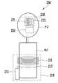
도 2는 본 발명에 따른 인공 망막 구동 장치(200)를 나타낸 도면이다.2 is a view showing the artificial
도 2를 참조하면, 본 발명에 따른 인공 망막 구동 장치(200)는, 사용자 신체의 소정 부위(예를 들면, 허리)에 장착된 제1 구동 회로(210)와 사용자의 안구 내에 장착된 제2 구동 회로(230)의 공진에 의해 안구 내의 인공 망막 회로(250)에 무선으로 전력을 공급할 수 있도록 구성되어 있다.Referring to FIG. 2, the artificial
상기 제1 구동 회로(210)는 1차 코일(211), 파워 코일(213) 및 파워 공급부(215)를 포함하며, 상기 제2 구동 회로(230)는 2차 코일(231) 및 로드 코일(233)을 포함한다.The
상기 1차 코일(211)은 사용자의 허리를 감싸는 형태로 감겨지는 것이 바람직 하며, 활동의 편리성을 위해 권선된 형태로 허리띠에 장착되는 것이 더 바람직하다.The
이 때, 상기 1차 코일(211)의 직경은 20cm 내지 60cm 정도인 것이 바람직하며, 턴수는 5 내지 10 정도가 적당하다.At this time, the diameter of the
상기 1차 코일(211)의 나선도(helicity)는 시계방향 또는 반시계방향이 될 수 있으며, 본 실시예에서 상기 1차 코일(211)은 반시계방향의 나선도를 갖는다.The helicity of the
상기 파워 코일(213)은 상기 1차 코일(211)에 최대한 밀접하게 위치하되, 상기 1차 코일(211)과의 공진을 위해 상기 1차 코일(211)에 완전히 접촉되지 않는 것이 바람직하다.The
상기 파워 코일(213)의 턴수는 1이면 충분하며, 상기 1차 코일(211)과 동일방향의 나선도를 갖는다. 여기에서, 상기 파워 코일(213)은 1턴 코일이므로, 신호 포트에서 접지 포트를 바라보는 방향을 기준으로 나선도를 정한다.The number of turns of the
즉, 상기 파워 공급부(215)로부터 상기 파워 코일(213)에 전력이 공급되면, 상기 파워 코일(213)과 상기 1차 코일(211)의 공진에 의해 상기 공급 전력이 상기 1차 코일(211)로 전송된다.That is, when electric power is supplied from the
상기 2차 코일(231)은 안구 뒤쪽의 시신경부에 장착되며, 상기 1차 코일(211)과 반대방향의 나선도를 갖는다. 본 실시예에서 상기 2차 코일(231)은 시계방향의 나선도를 갖는다.The
상기 로드 코일(233)은 상기 2차 코일(231)에 최대한 밀접하게 위치하되, 상기 2차 코일(231)과의 공진을 위해 상기 2차 코일(231)에 완전히 접촉되지 않는 것 이 바람직하다.The
상기 로드 코일(233)의 턴수는 1이면 충분하며, 상기 2차 코일(231)과 동일방향의 나선도를 갖는다.The number of turns of the
즉, 상기 1차 코일(211)과 상기 2차 코일(231)의 공진에 의해 상기 1차 코일(211)에 전송된 공급 전력이 상기 2차 코일(231)로 무선 전송되며, 상기 2차 코일(231)과 상기 로드 코일(233)의 공진에 의해 상기 공급 전력이 상기 로드 코일(233)을 통해 상기 인공 망막 회로(250)로 공급된다.That is, the supply power transmitted to the
상기 인공 망막 회로(250)는 정류회로, 광수용기(photoreceptor) 회로, 망막 자극 회로 등을 포함하며, 이와 같은 인공 망막 회로의 구조는 당업자에게 잘 알려진 기술이므로 이에 대한 자세한 설명은 생략한다.The artificial
본 발명에 따른 인공 망막 구동 장치(200)는 사용자의 허리와 안구 내에 각각 장착된 1차 코일(211)과 2차 코일(231)의 공진에 의하여 1m 정도의 중거리 내에서 인공 망막 회로(250)에 무선으로 전력을 전송할 수 있는 것에 가장 큰 특징이 있는 바, 이하의 설명에서 본 발명에 따른 중거리 무선 전력 전송 기술에 대하여 보다 상세히 설명한다.The
도 3은 도 2에서 파워 코일(213) 및 로드 코일(233)의 나선도에 따른 전력 전송 효율을 나타낸 도면이다.3 is a diagram illustrating power transmission efficiency according to spiral diagrams of the
도 3에 나타난 바와 같이, 파워 코일(213)이 1차 코일(211)과 동일방향의 나선도를 가지며, 로드 코일(233)이 2차 코일(231)과 동일방향의 나선도를 갖는 경우, 전력 전송 효율이 최대인 것을 알 수 있다.As shown in FIG. 3, when the
도 4a는 도 2에서 1차 코일(211)과 2차 코일(231)이 서로 동일방향의 나선도를 갖는 경우 두 코일의 회전축 각도에 따른 전력 전송 효율을 나타낸 도면이며, 도 4b는 도 2에서 1차 코일(211)과 2차 코일(231)이 서로 반대방향의 나선도를 갖는 경우 두 코일의 회전축 각도에 따른 전력 전송 효율을 나타낸 도면이다.FIG. 4A is a diagram illustrating power transmission efficiency according to rotation shaft angles of two coils when the
도 4a에 나타난 바와 같이, 1차 코일(211)과 2차 코일(231)이 서로 동일방향의 나선도를 갖는 경우, 두 코일의 회전축 각도가 증가함에 따라 전력 전송 효율이 감소하며, 두 코일의 회전축 각도의 변화에 따라 전력 전송 효율이 큰 폭으로 변화되는 것을 알 수 있다.As shown in FIG. 4A, when the
이에 비하여, 도 4b에 나타난 바와 같이, 1차 코일(211)과 2차 코일(231)이 서로 반대방향의 나선도를 갖는 경우, 두 코일의 회전축 각도가 증가함에 따라 전력 전송 효율이 증가하며, 두 코일의 회전축 각도의 변화에 따른 전력 전송 효율의 변화가 적은 것을 알 수 있다.On the contrary, as shown in FIG. 4B, when the
즉, 본 발명에서는 전력 전송 효율을 극대화시키기 위해 1차 코일(211)과 2차 코일(231)이 서로 반대방향의 나선도를 갖도록 하면서, 상기 파워 코일(213)은 상기 1차 코일(211)과 동일방향의 나선도를 갖도록 하고, 상기 로드 코일(233)은 상기 2차 코일(231)과 동일방향의 나선도를 갖도록 한다.That is, in the present invention, while the
따라서, 본 발명에 따른 인공 망막 구동 장치(200)에서는 상기 1차 코일(211)과 상기 2차 코일(231)의 회전축이 일치하지 않아도, 상기 1차 코일(211)과 상기 2차 코일(231)의 공진에 의해 1m 정도의 중거리 내에서 인공 망막 회로(250)에 무선으로 안정적인 전력을 공급할 수 있다.Therefore, in the artificial
한편, 상기 2차 코일(231)은 안구 내에 장착이 되므로, 상기 2차 코일(231)의 직경은 5cm 이하여야 한다.On the other hand, since the
즉, 상기 2차 코일(231)은 상기 1차 코일(211)에 비해 직경이 1/10 정도이면서 동일한 공진 주파수를 가져야 한다.That is, the
하지만, 코일의 직경이 작아지면 공진 주파수는 증가하게 되며, 이러한 결과는 도 5에서 확인할 수 있다.However, as the diameter of the coil decreases, the resonance frequency increases, which can be seen in FIG. 5.
도 5는 코일 직경에 따른 공진 주파수를 나타낸 도면으로, 도 5에 나타난 바와 같이 1턴당 높이가 3.8cm인 코일의 경우 코일 직경이 10cm 에서 5cm로 작아지면 공진 주파수는 40MHz 에서 100MHz로 증가하며, 1턴당 높이가 0.38cm인 코일의 경우 코일 직경이 10cm 에서 5cm로 작아지면 공진 주파수는 13MHz 에서 28MHz로 증가하는 것을 알 수 있다.5 is a diagram illustrating a resonant frequency according to a coil diameter. As shown in FIG. 5, in the case of a coil having a height of 3.8 cm per turn, when the coil diameter decreases from 10 cm to 5 cm, the resonant frequency increases from 40 MHz to 100 MHz. For coils with a height of 0.38 cm per turn, the resonant frequency increases from 13 MHz to 28 MHz as the coil diameter decreases from 10 cm to 5 cm.
따라서, 1차 코일(211) 보다 작은 직경을 갖는 2차 코일(231)이 1차 코일(211)과 동일한 공진 주파수를 갖도록 하기 위해서는 1차 코일(211)의 1턴당 높이 보다 2차 코일(231)의 1턴당 높이가 높아야 하며, 이에 대하여 도 6을 참조하여 더 자세히 설명하면 다음과 같다.Accordingly, in order for the
도 6은 도 2에서 2차 코일(231)의 직경과 1턴당 높이를 변화시킨 경우의 주파수 특성을 나타낸 도면이다.FIG. 6 is a diagram illustrating frequency characteristics when the diameter of the
도 6에 나타난 바와 같이, 2차 코일(231)의 직경은 줄이고 1턴당 높이를 증가시킨 경우 전력 전송 효율이 향상되는 것을 알 수 있다. 이 때, 2차 코일(231)의 턴수를 1차 코일(211)의 턴수 보다 크게 하여 2차 코일(231)이 1차 코일(211)과 동 일한 공진 주파수를 갖도록 하는 것도 가능하다.As shown in FIG. 6, it can be seen that the power transmission efficiency is improved when the diameter of the
상술한 바와 같이, 공진 주파수는 같으나 서로 반대방향의 나선도를 갖는 1차 코일(211)과 2차 코일(231)을 각각 허리와 안구에 장착한 상태에서, 파워 공급부(215)로부터 파워 코일(213)을 통해 1차 코일(211)에 전력이 공급되면, 1차 코일(211)과 2차 코일(231)의 공진에 의하여 상기 공급 전력이 2차 코일(231)로 무선 전송된다. 이렇게 상기 공급 전력이 2차 코일(231)로 무선 전송되면, 2차 코일(231)과 로드 코일(233)의 공진에 의해 상기 공급 전력이 로드 코일(233)을 통해 인공 망막 회로(250)에 공급되므로, 결과적으로 1m 정도의 중거리 내에서 인공 망막 회로(250)에 무선으로 전력을 공급할 수 있다.As described above, in the state where the
따라서, 본 발명에 따른 인공 망막 구동 장치(200)는, 수정체 내에 코일을 삽입하는 어려움을 해결할 수 있을 뿐만 아니라, 인공 안경을 사용하지 않아도 되므로 사용자에게 편리함을 제공할 수 있으며, 종래의 인공 안경과 수정체간의 정렬 및 거리 문제에 따른 불안정한 전력 공급 문제를 해결할 수 있다.Therefore, the artificial
게다가, 본 발명에 따른 인공 망막 구동 장치(200)는, 상기 인공 망막 회로(250)에 1턴의 로드 코일(233)을 연결하여 안구 내에 삽입한 다음 상기 로드 코일(233)과 인접한 위치에 2차 코일(231)을 배치하기만 하면 되므로, 2차 코일(231)과 인공 망막 회로(250)를 연결하는데 따른 어려움을 크게 감소시킬 수 있다.In addition, the artificial
이제까지 본 발명에 대하여 그 바람직한 실시예들을 중심으로 설명하였다. 그러나, 본 발명의 실시예는 당업계에서 통상의 지식을 가진 자에게 본 발명을 보다 완전하게 설명하기 위하여 제공되어지는 것으로, 본 발명의 범위가 상기의 실시 예에 한정되는 것은 아니며, 여러 가지 다른 형태로 변형이 가능함은 물론이다.So far, the present invention has been described based on the preferred embodiments. However, embodiments of the present invention is provided to more fully describe the present invention to those skilled in the art, the scope of the present invention is not limited to the above embodiments, various other Of course, the shape can be modified.
도 1은 인공 망막에 무선으로 전력을 공급하는 종래의 방법을 설명하기 위한 도면이다.1 is a view for explaining a conventional method for wirelessly powering the artificial retina.
도 2는 본 발명에 따른 인공 망막 구동 장치를 나타낸 도면이다.2 is a view showing the artificial retina driving apparatus according to the present invention.
도 3은 도 2에서 파워 코일 및 로드 코일의 나선도에 따른 전력 전송 효율을 나타낸 도면이다.3 is a diagram illustrating power transmission efficiency according to spiral diagrams of a power coil and a load coil in FIG. 2.
도 4a는 도 2에서 1차 코일과 2차 코일이 서로 동일방향의 나선도를 갖는 경우 두 코일의 회전축 각도에 따른 전력 전송 효율을 나타낸 도면이며, 도 4b는 도 2에서 1차 코일과 2차 코일이 서로 반대방향의 나선도를 갖는 경우 두 코일의 회전축 각도에 따른 전력 전송 효율을 나타낸 도면이다.FIG. 4A is a diagram illustrating power transmission efficiency according to rotation shaft angles of two coils when the primary coil and the secondary coil have the same spiral direction in FIG. 2, and FIG. 4B is the primary coil and the secondary coil in FIG. 2. In the case where the coils have opposite spirals, power transmission efficiency according to the rotation axis angle of the two coils is shown.
도 5는 코일 직경에 따른 공진 주파수를 나타낸 도면이다.5 is a diagram illustrating a resonance frequency according to a coil diameter.
도 6은 도 2에서 2차 코일의 직경과 1턴당 높이를 변화시킨 경우의 주파수 특성을 나타낸 도면이다.FIG. 6 is a diagram illustrating frequency characteristics when the diameter of the secondary coil and the height per turn are changed in FIG. 2.
* 도면의 주요부분에 대한 부호의 설명 *Explanation of symbols on the main parts of the drawings
110 : 인공 안경110: artificial glasses
111 : 1차 코일111: primary coil
131 : 2차 코일131: secondary coil
133 : 전선133: wires
140 : 변환 회로140: conversion circuit
150 : 인공 망막 회로150: artificial retina circuit
200 : 인공 망막 구동 장치200: artificial retina driving device
210 : 제1 구동 회로210: first driving circuit
211 : 1차 코일211: primary coil
213 : 파워 코일213: Power Coil
215 : 파워 공급부215: power supply
230 : 제2 구동 회로230: second driving circuit
231 : 2차 코일231: secondary coil
233 : 로드 코일233: load coil
250 : 인공 망막 회로250: artificial retina circuit
Claims (11)
Translated fromKoreanPriority Applications (2)
| Application Number | Priority Date | Filing Date | Title |
|---|---|---|---|
| KR1020080100337AKR101025743B1 (en) | 2008-10-13 | 2008-10-13 | Artificial retina driving device using medium range wireless power transmission technology |
| US12/477,908US20100094381A1 (en) | 2008-10-13 | 2009-06-04 | Apparatus for driving artificial retina using medium-range wireless power transmission technique |
Applications Claiming Priority (1)
| Application Number | Priority Date | Filing Date | Title |
|---|---|---|---|
| KR1020080100337AKR101025743B1 (en) | 2008-10-13 | 2008-10-13 | Artificial retina driving device using medium range wireless power transmission technology |
Publications (2)
| Publication Number | Publication Date |
|---|---|
| KR20100041244A KR20100041244A (en) | 2010-04-22 |
| KR101025743B1true KR101025743B1 (en) | 2011-04-04 |
Family
ID=42099599
Family Applications (1)
| Application Number | Title | Priority Date | Filing Date |
|---|---|---|---|
| KR1020080100337AActiveKR101025743B1 (en) | 2008-10-13 | 2008-10-13 | Artificial retina driving device using medium range wireless power transmission technology |
Country Status (2)
| Country | Link |
|---|---|
| US (1) | US20100094381A1 (en) |
| KR (1) | KR101025743B1 (en) |
Families Citing this family (98)
| Publication number | Priority date | Publication date | Assignee | Title |
|---|---|---|---|---|
| US7825543B2 (en) | 2005-07-12 | 2010-11-02 | Massachusetts Institute Of Technology | Wireless energy transfer |
| US9421388B2 (en) | 2007-06-01 | 2016-08-23 | Witricity Corporation | Power generation for implantable devices |
| US8115448B2 (en) | 2007-06-01 | 2012-02-14 | Michael Sasha John | Systems and methods for wireless power |
| CN102099958B (en) | 2008-05-14 | 2013-12-25 | 麻省理工学院 | Wireless power transfer including interference enhancement |
| US8933594B2 (en) | 2008-09-27 | 2015-01-13 | Witricity Corporation | Wireless energy transfer for vehicles |
| US8629578B2 (en) | 2008-09-27 | 2014-01-14 | Witricity Corporation | Wireless energy transfer systems |
| US8587153B2 (en) | 2008-09-27 | 2013-11-19 | Witricity Corporation | Wireless energy transfer using high Q resonators for lighting applications |
| US8461720B2 (en)* | 2008-09-27 | 2013-06-11 | Witricity Corporation | Wireless energy transfer using conducting surfaces to shape fields and reduce loss |
| US8692412B2 (en)* | 2008-09-27 | 2014-04-08 | Witricity Corporation | Temperature compensation in a wireless transfer system |
| US9544683B2 (en) | 2008-09-27 | 2017-01-10 | Witricity Corporation | Wirelessly powered audio devices |
| US9093853B2 (en) | 2008-09-27 | 2015-07-28 | Witricity Corporation | Flexible resonator attachment |
| US8686598B2 (en) | 2008-09-27 | 2014-04-01 | Witricity Corporation | Wireless energy transfer for supplying power and heat to a device |
| US9184595B2 (en) | 2008-09-27 | 2015-11-10 | Witricity Corporation | Wireless energy transfer in lossy environments |
| US8497601B2 (en) | 2008-09-27 | 2013-07-30 | Witricity Corporation | Wireless energy transfer converters |
| US8569914B2 (en) | 2008-09-27 | 2013-10-29 | Witricity Corporation | Wireless energy transfer using object positioning for improved k |
| US8410636B2 (en) | 2008-09-27 | 2013-04-02 | Witricity Corporation | Low AC resistance conductor designs |
| US8957549B2 (en) | 2008-09-27 | 2015-02-17 | Witricity Corporation | Tunable wireless energy transfer for in-vehicle applications |
| US9744858B2 (en) | 2008-09-27 | 2017-08-29 | Witricity Corporation | System for wireless energy distribution in a vehicle |
| US8552592B2 (en)* | 2008-09-27 | 2013-10-08 | Witricity Corporation | Wireless energy transfer with feedback control for lighting applications |
| US9105959B2 (en) | 2008-09-27 | 2015-08-11 | Witricity Corporation | Resonator enclosure |
| US8772973B2 (en)* | 2008-09-27 | 2014-07-08 | Witricity Corporation | Integrated resonator-shield structures |
| US8643326B2 (en)* | 2008-09-27 | 2014-02-04 | Witricity Corporation | Tunable wireless energy transfer systems |
| US8324759B2 (en)* | 2008-09-27 | 2012-12-04 | Witricity Corporation | Wireless energy transfer using magnetic materials to shape field and reduce loss |
| US8400017B2 (en) | 2008-09-27 | 2013-03-19 | Witricity Corporation | Wireless energy transfer for computer peripheral applications |
| US8937408B2 (en) | 2008-09-27 | 2015-01-20 | Witricity Corporation | Wireless energy transfer for medical applications |
| US8304935B2 (en)* | 2008-09-27 | 2012-11-06 | Witricity Corporation | Wireless energy transfer using field shaping to reduce loss |
| US9601261B2 (en) | 2008-09-27 | 2017-03-21 | Witricity Corporation | Wireless energy transfer using repeater resonators |
| US8461722B2 (en) | 2008-09-27 | 2013-06-11 | Witricity Corporation | Wireless energy transfer using conducting surfaces to shape field and improve K |
| US9515494B2 (en) | 2008-09-27 | 2016-12-06 | Witricity Corporation | Wireless power system including impedance matching network |
| US8487480B1 (en) | 2008-09-27 | 2013-07-16 | Witricity Corporation | Wireless energy transfer resonator kit |
| US9601266B2 (en) | 2008-09-27 | 2017-03-21 | Witricity Corporation | Multiple connected resonators with a single electronic circuit |
| US8901779B2 (en) | 2008-09-27 | 2014-12-02 | Witricity Corporation | Wireless energy transfer with resonator arrays for medical applications |
| US8901778B2 (en) | 2008-09-27 | 2014-12-02 | Witricity Corporation | Wireless energy transfer with variable size resonators for implanted medical devices |
| US8476788B2 (en) | 2008-09-27 | 2013-07-02 | Witricity Corporation | Wireless energy transfer with high-Q resonators using field shaping to improve K |
| US9601270B2 (en) | 2008-09-27 | 2017-03-21 | Witricity Corporation | Low AC resistance conductor designs |
| US8692410B2 (en)* | 2008-09-27 | 2014-04-08 | Witricity Corporation | Wireless energy transfer with frequency hopping |
| US9396867B2 (en) | 2008-09-27 | 2016-07-19 | Witricity Corporation | Integrated resonator-shield structures |
| US8461721B2 (en) | 2008-09-27 | 2013-06-11 | Witricity Corporation | Wireless energy transfer using object positioning for low loss |
| US8946938B2 (en) | 2008-09-27 | 2015-02-03 | Witricity Corporation | Safety systems for wireless energy transfer in vehicle applications |
| US8482158B2 (en) | 2008-09-27 | 2013-07-09 | Witricity Corporation | Wireless energy transfer using variable size resonators and system monitoring |
| US9065423B2 (en) | 2008-09-27 | 2015-06-23 | Witricity Corporation | Wireless energy distribution system |
| US8441154B2 (en) | 2008-09-27 | 2013-05-14 | Witricity Corporation | Multi-resonator wireless energy transfer for exterior lighting |
| US8587155B2 (en)* | 2008-09-27 | 2013-11-19 | Witricity Corporation | Wireless energy transfer using repeater resonators |
| US8723366B2 (en) | 2008-09-27 | 2014-05-13 | Witricity Corporation | Wireless energy transfer resonator enclosures |
| US8947186B2 (en) | 2008-09-27 | 2015-02-03 | Witricity Corporation | Wireless energy transfer resonator thermal management |
| US9035499B2 (en) | 2008-09-27 | 2015-05-19 | Witricity Corporation | Wireless energy transfer for photovoltaic panels |
| US8669676B2 (en) | 2008-09-27 | 2014-03-11 | Witricity Corporation | Wireless energy transfer across variable distances using field shaping with magnetic materials to improve the coupling factor |
| US9577436B2 (en) | 2008-09-27 | 2017-02-21 | Witricity Corporation | Wireless energy transfer for implantable devices |
| US8963488B2 (en) | 2008-09-27 | 2015-02-24 | Witricity Corporation | Position insensitive wireless charging |
| US8912687B2 (en) | 2008-09-27 | 2014-12-16 | Witricity Corporation | Secure wireless energy transfer for vehicle applications |
| EP3179640A1 (en)* | 2008-09-27 | 2017-06-14 | WiTricity Corporation | Wireless energy transfer systems |
| US8922066B2 (en) | 2008-09-27 | 2014-12-30 | Witricity Corporation | Wireless energy transfer with multi resonator arrays for vehicle applications |
| US8907531B2 (en) | 2008-09-27 | 2014-12-09 | Witricity Corporation | Wireless energy transfer with variable size resonators for medical applications |
| US9106203B2 (en) | 2008-09-27 | 2015-08-11 | Witricity Corporation | Secure wireless energy transfer in medical applications |
| US8928276B2 (en) | 2008-09-27 | 2015-01-06 | Witricity Corporation | Integrated repeaters for cell phone applications |
| US9160203B2 (en) | 2008-09-27 | 2015-10-13 | Witricity Corporation | Wireless powered television |
| US9246336B2 (en) | 2008-09-27 | 2016-01-26 | Witricity Corporation | Resonator optimizations for wireless energy transfer |
| US8471410B2 (en) | 2008-09-27 | 2013-06-25 | Witricity Corporation | Wireless energy transfer over distance using field shaping to improve the coupling factor |
| US8598743B2 (en) | 2008-09-27 | 2013-12-03 | Witricity Corporation | Resonator arrays for wireless energy transfer |
| US8466583B2 (en) | 2008-09-27 | 2013-06-18 | Witricity Corporation | Tunable wireless energy transfer for outdoor lighting applications |
| US9318922B2 (en) | 2008-09-27 | 2016-04-19 | Witricity Corporation | Mechanically removable wireless power vehicle seat assembly |
| US8362651B2 (en)* | 2008-10-01 | 2013-01-29 | Massachusetts Institute Of Technology | Efficient near-field wireless energy transfer using adiabatic system variations |
| US8690749B1 (en) | 2009-11-02 | 2014-04-08 | Anthony Nunez | Wireless compressible heart pump |
| KR101055560B1 (en)* | 2010-05-19 | 2011-08-08 | 삼성전기주식회사 | Stereoscopic image display for transmitting and receiving power wirelessly |
| US9602168B2 (en) | 2010-08-31 | 2017-03-21 | Witricity Corporation | Communication in wireless energy transfer systems |
| US9948145B2 (en) | 2011-07-08 | 2018-04-17 | Witricity Corporation | Wireless power transfer for a seat-vest-helmet system |
| KR101239289B1 (en)* | 2011-08-03 | 2013-03-06 | 한양대학교 산학협력단 | Wireless power transfer system |
| CN108110907B (en) | 2011-08-04 | 2022-08-02 | 韦特里西提公司 | Tunable wireless power supply architecture |
| EP2754222B1 (en) | 2011-09-09 | 2015-11-18 | Witricity Corporation | Foreign object detection in wireless energy transfer systems |
| US20130062966A1 (en) | 2011-09-12 | 2013-03-14 | Witricity Corporation | Reconfigurable control architectures and algorithms for electric vehicle wireless energy transfer systems |
| US9318257B2 (en) | 2011-10-18 | 2016-04-19 | Witricity Corporation | Wireless energy transfer for packaging |
| CA2853824A1 (en) | 2011-11-04 | 2013-05-10 | Witricity Corporation | Wireless energy transfer modeling tool |
| JP2015508987A (en) | 2012-01-26 | 2015-03-23 | ワイトリシティ コーポレーションWitricity Corporation | Wireless energy transmission with reduced field |
| US9343922B2 (en) | 2012-06-27 | 2016-05-17 | Witricity Corporation | Wireless energy transfer for rechargeable batteries |
| US9287607B2 (en) | 2012-07-31 | 2016-03-15 | Witricity Corporation | Resonator fine tuning |
| US9595378B2 (en) | 2012-09-19 | 2017-03-14 | Witricity Corporation | Resonator enclosure |
| EP2909912B1 (en) | 2012-10-19 | 2022-08-10 | WiTricity Corporation | Foreign object detection in wireless energy transfer systems |
| US9842684B2 (en) | 2012-11-16 | 2017-12-12 | Witricity Corporation | Systems and methods for wireless power system with improved performance and/or ease of use |
| US9857821B2 (en) | 2013-08-14 | 2018-01-02 | Witricity Corporation | Wireless power transfer frequency adjustment |
| US9780573B2 (en) | 2014-02-03 | 2017-10-03 | Witricity Corporation | Wirelessly charged battery system |
| US9952266B2 (en) | 2014-02-14 | 2018-04-24 | Witricity Corporation | Object detection for wireless energy transfer systems |
| US9892849B2 (en) | 2014-04-17 | 2018-02-13 | Witricity Corporation | Wireless power transfer systems with shield openings |
| US9842687B2 (en) | 2014-04-17 | 2017-12-12 | Witricity Corporation | Wireless power transfer systems with shaped magnetic components |
| US9837860B2 (en) | 2014-05-05 | 2017-12-05 | Witricity Corporation | Wireless power transmission systems for elevators |
| JP2017518018A (en) | 2014-05-07 | 2017-06-29 | ワイトリシティ コーポレーションWitricity Corporation | Foreign object detection in wireless energy transmission systems |
| US9954375B2 (en) | 2014-06-20 | 2018-04-24 | Witricity Corporation | Wireless power transfer systems for surfaces |
| US10574091B2 (en) | 2014-07-08 | 2020-02-25 | Witricity Corporation | Enclosures for high power wireless power transfer systems |
| CN107258046B (en) | 2014-07-08 | 2020-07-17 | 无线电力公司 | Resonator equalization in wireless power transfer systems |
| US9843217B2 (en) | 2015-01-05 | 2017-12-12 | Witricity Corporation | Wireless energy transfer for wearables |
| US10248899B2 (en) | 2015-10-06 | 2019-04-02 | Witricity Corporation | RFID tag and transponder detection in wireless energy transfer systems |
| US9929721B2 (en) | 2015-10-14 | 2018-03-27 | Witricity Corporation | Phase and amplitude detection in wireless energy transfer systems |
| WO2017070227A1 (en) | 2015-10-19 | 2017-04-27 | Witricity Corporation | Foreign object detection in wireless energy transfer systems |
| WO2017070009A1 (en) | 2015-10-22 | 2017-04-27 | Witricity Corporation | Dynamic tuning in wireless energy transfer systems |
| US10075019B2 (en) | 2015-11-20 | 2018-09-11 | Witricity Corporation | Voltage source isolation in wireless power transfer systems |
| WO2017136491A1 (en) | 2016-02-02 | 2017-08-10 | Witricity Corporation | Controlling wireless power transfer systems |
| CN114123540B (en) | 2016-02-08 | 2024-08-20 | 韦特里西提公司 | Variable capacitance device and high-power wireless energy transmission system |
| WO2019006376A1 (en) | 2017-06-29 | 2019-01-03 | Witricity Corporation | Protection and control of wireless power systems |
| CN108693650A (en)* | 2018-05-30 | 2018-10-23 | 哈尔滨工业大学 | A kind of Worn type glasses for wireless power |
Citations (3)
| Publication number | Priority date | Publication date | Assignee | Title |
|---|---|---|---|---|
| US20020193845A1 (en) | 1999-03-24 | 2002-12-19 | Second Sight, Llc. | Optical Communications System for an Implantable Device |
| JP2004089399A (en) | 2002-08-30 | 2004-03-25 | Nidek Co Ltd | Intraocular implantation device |
| JP2006068404A (en)* | 2004-09-03 | 2006-03-16 | Tohoku Univ | Artificial eye system |
Family Cites Families (98)
| Publication number | Priority date | Publication date | Assignee | Title |
|---|---|---|---|---|
| US6850252B1 (en)* | 1999-10-05 | 2005-02-01 | Steven M. Hoffberg | Intelligent electronic appliance system and method |
| US5493692A (en)* | 1993-12-03 | 1996-02-20 | Xerox Corporation | Selective delivery of electronic messages in a multiple computer system based on context and environment of a user |
| US6571279B1 (en)* | 1997-12-05 | 2003-05-27 | Pinpoint Incorporated | Location enhanced information delivery system |
| WO1997019415A2 (en)* | 1995-11-07 | 1997-05-29 | Cadis, Inc. | Search engine for remote object oriented database management system |
| US6014638A (en)* | 1996-05-29 | 2000-01-11 | America Online, Inc. | System for customizing computer displays in accordance with user preferences |
| US6021403A (en)* | 1996-07-19 | 2000-02-01 | Microsoft Corporation | Intelligent user assistance facility |
| US6047234A (en)* | 1997-10-16 | 2000-04-04 | Navigation Technologies Corporation | System and method for updating, enhancing or refining a geographic database using feedback |
| US6708203B1 (en)* | 1997-10-20 | 2004-03-16 | The Delfin Project, Inc. | Method and system for filtering messages based on a user profile and an informational processing system event |
| US6157924A (en)* | 1997-11-07 | 2000-12-05 | Bell & Howell Mail Processing Systems Company | Systems, methods, and computer program products for delivering information in a preferred medium |
| US6141010A (en)* | 1998-07-17 | 2000-10-31 | B. E. Technology, Llc | Computer interface method and apparatus with targeted advertising |
| US6317722B1 (en)* | 1998-09-18 | 2001-11-13 | Amazon.Com, Inc. | Use of electronic shopping carts to generate personal recommendations |
| US6845370B2 (en)* | 1998-11-12 | 2005-01-18 | Accenture Llp | Advanced information gathering for targeted activities |
| US6523172B1 (en)* | 1998-12-17 | 2003-02-18 | Evolutionary Technologies International, Inc. | Parser translator system and method |
| US6397307B2 (en)* | 1999-02-23 | 2002-05-28 | Legato Systems, Inc. | Method and system for mirroring and archiving mass storage |
| US6694316B1 (en)* | 1999-03-23 | 2004-02-17 | Microstrategy Inc. | System and method for a subject-based channel distribution of automatic, real-time delivery of personalized informational and transactional data |
| US7181438B1 (en)* | 1999-07-21 | 2007-02-20 | Alberti Anemometer, Llc | Database access system |
| US7010492B1 (en)* | 1999-09-30 | 2006-03-07 | International Business Machines Corporation | Method and apparatus for dynamic distribution of controlled and additional selective overlays in a streaming media |
| US6968313B1 (en)* | 1999-11-15 | 2005-11-22 | H Three, Inc. | Method and apparatus for facilitating and tracking personal referrals |
| US7822823B2 (en)* | 1999-12-14 | 2010-10-26 | Neeraj Jhanji | Systems for communicating current and future activity information among mobile internet users and methods therefor |
| US6845448B1 (en)* | 2000-01-07 | 2005-01-18 | Pennar Software Corporation | Online repository for personal information |
| US20020035605A1 (en)* | 2000-01-26 | 2002-03-21 | Mcdowell Mark | Use of presence and location information concerning wireless subscribers for instant messaging and mobile commerce |
| AU2001245447A1 (en)* | 2000-03-06 | 2001-09-17 | Kanisa Inc. | A system and method for providing an intelligent multi-step dialog with a user |
| US7320025B1 (en)* | 2002-03-18 | 2008-01-15 | Music Choice | Systems and methods for providing a broadcast entertainment service and an on-demand entertainment service |
| US7725523B2 (en)* | 2000-04-11 | 2010-05-25 | Bolnick David A | System, method and computer program product for gathering and delivering personalized user information |
| US6985839B1 (en)* | 2000-05-05 | 2006-01-10 | Technocom Corporation | System and method for wireless location coverage and prediction |
| US6957214B2 (en)* | 2000-06-23 | 2005-10-18 | The Johns Hopkins University | Architecture for distributed database information access |
| US6954778B2 (en)* | 2000-07-12 | 2005-10-11 | Microsoft Corporation | System and method for accessing directory service via an HTTP URL |
| GB0017380D0 (en)* | 2000-07-14 | 2000-08-30 | Mailround Com Limited | Information communication system |
| US6494457B2 (en)* | 2000-07-26 | 2002-12-17 | Shelly Conte | Enhanced hide and seek game and method of playing game |
| ATE236489T1 (en)* | 2000-09-11 | 2003-04-15 | Mediabricks Ab | METHOD FOR PROVIDING MEDIA CONTENT VIA A DIGITAL NETWORK |
| US7865306B2 (en)* | 2000-09-28 | 2011-01-04 | Michael Mays | Devices, methods, and systems for managing route-related information |
| US7925967B2 (en)* | 2000-11-21 | 2011-04-12 | Aol Inc. | Metadata quality improvement |
| US6701311B2 (en)* | 2001-02-07 | 2004-03-02 | International Business Machines Corporation | Customer self service system for resource search and selection |
| US20030032409A1 (en)* | 2001-03-16 | 2003-02-13 | Hutcheson Stewart Douglas | Method and system for distributing content over a wireless communications system |
| US7266085B2 (en)* | 2001-03-21 | 2007-09-04 | Stine John A | Access and routing protocol for ad hoc network using synchronous collision resolution and node state dissemination |
| US7039643B2 (en)* | 2001-04-10 | 2006-05-02 | Adobe Systems Incorporated | System, method and apparatus for converting and integrating media files |
| CA2452380A1 (en)* | 2001-05-08 | 2002-11-14 | Ipool Corporation | Privacy protection system and method |
| US7194512B1 (en)* | 2001-06-26 | 2007-03-20 | Palm, Inc. | Method and apparatus for wirelessly networked distributed resource usage for data gathering |
| US20030009495A1 (en)* | 2001-06-29 | 2003-01-09 | Akli Adjaoute | Systems and methods for filtering electronic content |
| US20030008661A1 (en)* | 2001-07-03 | 2003-01-09 | Joyce Dennis P. | Location-based content delivery |
| US20030009367A1 (en)* | 2001-07-06 | 2003-01-09 | Royce Morrison | Process for consumer-directed prescription influence and health care product marketing |
| EP1282054A1 (en)* | 2001-08-01 | 2003-02-05 | Alcatel | Method for implementing an appointment service for participants of a communication network, and a service processor and program module for such |
| US7284191B2 (en)* | 2001-08-13 | 2007-10-16 | Xerox Corporation | Meta-document management system with document identifiers |
| US7185286B2 (en)* | 2001-08-28 | 2007-02-27 | Nvidia International, Inc. | Interface for mobilizing content and transactions on multiple classes of devices |
| US20060069616A1 (en)* | 2004-09-30 | 2006-03-30 | David Bau | Determining advertisements using user behavior information such as past navigation information |
| US7680796B2 (en)* | 2003-09-03 | 2010-03-16 | Google, Inc. | Determining and/or using location information in an ad system |
| US20040015588A1 (en)* | 2002-07-22 | 2004-01-22 | Web.De Ag | Communications environment having multiple web sites |
| US7194463B2 (en)* | 2002-05-28 | 2007-03-20 | Xerox Corporation | Systems and methods for constrained anisotropic diffusion routing within an ad hoc network |
| US12299693B2 (en)* | 2002-06-14 | 2025-05-13 | Dizpersion Corporation | Method and system for providing network based target advertising and encapsulation |
| US7707317B2 (en)* | 2002-07-01 | 2010-04-27 | Prolifiq Software Inc. | Adaptive electronic messaging |
| US7363345B2 (en)* | 2002-08-27 | 2008-04-22 | Aol Llc, A Delaware Limited Liability Company | Electronic notification delivery mechanism selection based on recipient presence information and notification content |
| US7570943B2 (en)* | 2002-08-29 | 2009-08-04 | Nokia Corporation | System and method for providing context sensitive recommendations to digital services |
| US7657907B2 (en)* | 2002-09-30 | 2010-02-02 | Sharp Laboratories Of America, Inc. | Automatic user profiling |
| US20050015599A1 (en)* | 2003-06-25 | 2005-01-20 | Nokia, Inc. | Two-phase hash value matching technique in message protection systems |
| US7840892B2 (en)* | 2003-08-29 | 2010-11-23 | Nokia Corporation | Organization and maintenance of images using metadata |
| US7849103B2 (en)* | 2003-09-10 | 2010-12-07 | West Services, Inc. | Relationship collaboration system |
| US7984037B2 (en)* | 2004-07-16 | 2011-07-19 | Canon Kabushiki Kaisha | Method for evaluating xpath-like fragment identifiers of audio-visual content |
| US20080046298A1 (en)* | 2004-07-29 | 2008-02-21 | Ziv Ben-Yehuda | System and Method For Travel Planning |
| US7958115B2 (en)* | 2004-07-29 | 2011-06-07 | Yahoo! Inc. | Search systems and methods using in-line contextual queries |
| US20070043766A1 (en)* | 2005-08-18 | 2007-02-22 | Nicholas Frank C | Method and System for the Creating, Managing, and Delivery of Feed Formatted Content |
| US20060040719A1 (en)* | 2004-08-20 | 2006-02-23 | Jason Plimi | Fantasy sports league pre-draft logic method |
| US7865457B2 (en)* | 2004-08-25 | 2011-01-04 | International Business Machines Corporation | Knowledge management system automatically allocating expert resources |
| US20060053058A1 (en)* | 2004-08-31 | 2006-03-09 | Philip Hotchkiss | System and method for gathering consumer feedback |
| US20060047563A1 (en)* | 2004-09-02 | 2006-03-02 | Keith Wardell | Method for optimizing a marketing campaign |
| US20060069612A1 (en)* | 2004-09-28 | 2006-03-30 | Microsoft Corporation | System and method for generating an orchestrated advertising campaign |
| WO2006089994A1 (en)* | 2005-01-12 | 2006-08-31 | Nokia Corporation | Name service in a multihop wireless ad hoc network |
| US7343364B2 (en)* | 2005-02-04 | 2008-03-11 | Efunds Corporation | Rules-based system architecture and systems using the same |
| US7466244B2 (en)* | 2005-04-21 | 2008-12-16 | Microsoft Corporation | Virtual earth rooftop overlay and bounding |
| US7899469B2 (en)* | 2005-07-12 | 2011-03-01 | Qwest Communications International, Inc. | User defined location based notification for a mobile communications device systems and methods |
| US7259668B2 (en)* | 2005-07-12 | 2007-08-21 | Qwest Communications International Inc. | Mapping the location of a mobile communications device systems and methods |
| JP2009521014A (en)* | 2005-08-26 | 2009-05-28 | スポット ランナー インコーポレイテッド | System and method for media planning, advertisement production, advertisement placement, and content customization |
| GB2430507A (en)* | 2005-09-21 | 2007-03-28 | Stephen Robert Ives | System for managing the display of sponsored links together with search results on a mobile/wireless device |
| US20070072591A1 (en)* | 2005-09-23 | 2007-03-29 | Mcgary Faith | Enhanced directory assistance system and method including location search functions |
| US20070073641A1 (en)* | 2005-09-23 | 2007-03-29 | Redcarpet, Inc. | Method and system for improving search results |
| US7496548B1 (en)* | 2005-09-26 | 2009-02-24 | Quintura, Inc. | Neural network for electronic search applications |
| GB0608966D0 (en)* | 2006-05-05 | 2006-06-14 | Norwegian University Of Life S | Method and product |
| US20080005313A1 (en)* | 2006-06-29 | 2008-01-03 | Microsoft Corporation | Using offline activity to enhance online searching |
| WO2008007364A2 (en)* | 2006-07-10 | 2008-01-17 | Vringo, Inc. | Pushed media content delivery |
| US20080028031A1 (en)* | 2006-07-25 | 2008-01-31 | Byron Lewis Bailey | Method and apparatus for managing instant messaging |
| US8568236B2 (en)* | 2006-07-28 | 2013-10-29 | Yahoo! Inc. | Fantasy sports agent |
| US20080040283A1 (en)* | 2006-08-11 | 2008-02-14 | Arcadyan Technology Corporation | Content protection system and method for enabling secure sharing of copy-protected content |
| US8099105B2 (en)* | 2006-09-19 | 2012-01-17 | Telecommunication Systems, Inc. | Device based trigger for location push event |
| US7656851B1 (en)* | 2006-10-12 | 2010-02-02 | Bae Systems Information And Electronic Systems Integration Inc. | Adaptive message routing for mobile ad HOC networks |
| WO2008134595A1 (en)* | 2007-04-27 | 2008-11-06 | Pelago, Inc. | Determining locations of interest based on user visits |
| US8321794B2 (en)* | 2007-06-28 | 2012-11-27 | Microsoft Corporation | Rich conference invitations with context |
| US8332402B2 (en)* | 2007-06-28 | 2012-12-11 | Apple Inc. | Location based media items |
| US20090012965A1 (en)* | 2007-07-01 | 2009-01-08 | Decisionmark Corp. | Network Content Objection Handling System and Method |
| US20090012934A1 (en)* | 2007-07-03 | 2009-01-08 | Corbis Corporation | Searching for rights limited media |
| US20090043844A1 (en)* | 2007-08-09 | 2009-02-12 | International Business Machines Corporation | System and method for name conflict resolution |
| US9946975B2 (en)* | 2007-08-24 | 2018-04-17 | At&T Intellectual Property I, L.P. | Method and apparatus to identify influencers |
| US8001002B2 (en)* | 2007-09-07 | 2011-08-16 | Microsoft Corporation | Interactively presenting advertising content offline |
| US8626297B2 (en)* | 2007-09-20 | 2014-01-07 | Boston Scientific Neuromodulation Corporation | Apparatus and methods for charging an implanted medical device power source |
| US20100013009A1 (en)* | 2007-12-14 | 2010-01-21 | James Pan | Structure and Method for Forming Trench Gate Transistors with Low Gate Resistance |
| US7865308B2 (en)* | 2007-12-28 | 2011-01-04 | Yahoo! Inc. | User-generated activity maps |
| US20100016704A1 (en)* | 2008-07-16 | 2010-01-21 | Naber John F | Method and system for monitoring a condition of an eye |
| US8153498B2 (en)* | 2008-08-29 | 2012-04-10 | Taiwan Semiconductor Manufacturing Company, Ltd. | Downsize polysilicon height for polysilicon resistor integration of replacement gate process |
| US20100063993A1 (en)* | 2008-09-08 | 2010-03-11 | Yahoo! Inc. | System and method for socially aware identity manager |
| KR101024149B1 (en)* | 2008-09-11 | 2011-03-22 | 야후! 인크. | How to register an advertisement on the electronic map using the advertisement registration reference information |
- 2008
- 2008-10-13KRKR1020080100337Apatent/KR101025743B1/enactiveActive
- 2009
- 2009-06-04USUS12/477,908patent/US20100094381A1/ennot_activeAbandoned
Patent Citations (3)
| Publication number | Priority date | Publication date | Assignee | Title |
|---|---|---|---|---|
| US20020193845A1 (en) | 1999-03-24 | 2002-12-19 | Second Sight, Llc. | Optical Communications System for an Implantable Device |
| JP2004089399A (en) | 2002-08-30 | 2004-03-25 | Nidek Co Ltd | Intraocular implantation device |
| JP2006068404A (en)* | 2004-09-03 | 2006-03-16 | Tohoku Univ | Artificial eye system |
Non-Patent Citations (1)
| Title |
|---|
| Science (vol 317, 2007.7.6., Wireless Power Transfer via Strongly Coupled Magnetic Resonances, pp 83~86)* |
Also Published As
| Publication number | Publication date |
|---|---|
| US20100094381A1 (en) | 2010-04-15 |
| KR20100041244A (en) | 2010-04-22 |
Similar Documents
| Publication | Publication Date | Title |
|---|---|---|
| KR101025743B1 (en) | Artificial retina driving device using medium range wireless power transmission technology | |
| US9844677B2 (en) | External controller/charger system for an implantable medical device capable of automatically providing data telemetry through a charging coil during a charging session | |
| JP6181305B2 (en) | Orientation and placement of inductive components to minimize noise coupling to the communication coil of an implantable medical device | |
| US10080893B2 (en) | Varying the effective coil area for an inductive transcutaneous power link | |
| EP2968740B1 (en) | Systems and methods for regulating inductive energy transfer to an implantable system | |
| EP3875143B1 (en) | System for supplying energy to an implantable medical device | |
| JP2006006950A (en) | Low-frequency transcutaneous energy transfer to implanted medical device | |
| CN107148296A (en) | For the peripheral control unit with the implantable medical device system by the battery-powered external charging coil of external electrical | |
| US11844952B2 (en) | System for wirelessly coupling in vivo | |
| US20120119700A1 (en) | Coil system | |
| CN104582635A (en) | 3-coil wireless power transfer system for ocular implants | |
| KR20120110927A (en) | Apparatus and system for wireless power transmission using dual transmitter coils | |
| KR100869229B1 (en) | Endoscopic Microcapsules Powered by Endoscopic Microcapsule Wireless Power Transfer System and Wireless Power Transfer System | |
| CN113300478A (en) | Anti-deviation wireless power transmission system for implantable medical equipment | |
| JP5396634B2 (en) | Power transmission circuit and visual reproduction assisting device having the same | |
| KR102565744B1 (en) | Apparatus for transmitting power wirelessly using capacitive coupling | |
| US20240350816A1 (en) | Devices with integrated concave coils | |
| CN111064285B (en) | Wireless energy signal transmission system for implantable device | |
| EP3193960B1 (en) | Implanted device with wireless energy transfer and external alignment feature | |
| KR102215654B1 (en) | Complex therapeutic device | |
| WO2025050104A1 (en) | Migraine alleviation device | |
| KR20250140423A (en) | Wireless power charging system | |
| AU711002B2 (en) | Compact inductive arrangement |
Legal Events
| Date | Code | Title | Description |
|---|---|---|---|
| A201 | Request for examination | ||
| PA0109 | Patent application | Patent event code:PA01091R01D Comment text:Patent Application Patent event date:20081013 | |
| PA0201 | Request for examination | ||
| PG1501 | Laying open of application | ||
| E902 | Notification of reason for refusal | ||
| PE0902 | Notice of grounds for rejection | Comment text:Notification of reason for refusal Patent event date:20100928 Patent event code:PE09021S01D | |
| E90F | Notification of reason for final refusal | ||
| PE0902 | Notice of grounds for rejection | Comment text:Final Notice of Reason for Refusal Patent event date:20101211 Patent event code:PE09021S02D | |
| E701 | Decision to grant or registration of patent right | ||
| PE0701 | Decision of registration | Patent event code:PE07011S01D Comment text:Decision to Grant Registration Patent event date:20110321 | |
| GRNT | Written decision to grant | ||
| PR0701 | Registration of establishment | Comment text:Registration of Establishment Patent event date:20110323 Patent event code:PR07011E01D | |
| PR1002 | Payment of registration fee | Payment date:20110324 End annual number:3 Start annual number:1 | |
| PG1601 | Publication of registration | ||
| FPAY | Annual fee payment | Payment date:20130730 Year of fee payment:18 | |
| PR1001 | Payment of annual fee | Payment date:20130730 Start annual number:4 End annual number:18 |