KR101024739B1 - Image sensor and manufacturing method of image sensor - Google Patents
Image sensor and manufacturing method of image sensorDownload PDFInfo
- Publication number
- KR101024739B1 KR101024739B1KR1020080096029AKR20080096029AKR101024739B1KR 101024739 B1KR101024739 B1KR 101024739B1KR 1020080096029 AKR1020080096029 AKR 1020080096029AKR 20080096029 AKR20080096029 AKR 20080096029AKR 101024739 B1KR101024739 B1KR 101024739B1
- Authority
- KR
- South Korea
- Prior art keywords
- layer
- interlayer insulating
- forming
- metal
- insulating layer
- Prior art date
- Legal status (The legal status is an assumption and is not a legal conclusion. Google has not performed a legal analysis and makes no representation as to the accuracy of the status listed.)
- Expired - Fee Related
Links
Images


Classifications
- H—ELECTRICITY
- H10—SEMICONDUCTOR DEVICES; ELECTRIC SOLID-STATE DEVICES NOT OTHERWISE PROVIDED FOR
- H10F—INORGANIC SEMICONDUCTOR DEVICES SENSITIVE TO INFRARED RADIATION, LIGHT, ELECTROMAGNETIC RADIATION OF SHORTER WAVELENGTH OR CORPUSCULAR RADIATION
- H10F39/00—Integrated devices, or assemblies of multiple devices, comprising at least one element covered by group H10F30/00, e.g. radiation detectors comprising photodiode arrays
- H10F39/011—Manufacture or treatment of image sensors covered by group H10F39/12
- H10F39/024—Manufacture or treatment of image sensors covered by group H10F39/12 of coatings or optical elements
- H—ELECTRICITY
- H10—SEMICONDUCTOR DEVICES; ELECTRIC SOLID-STATE DEVICES NOT OTHERWISE PROVIDED FOR
- H10F—INORGANIC SEMICONDUCTOR DEVICES SENSITIVE TO INFRARED RADIATION, LIGHT, ELECTROMAGNETIC RADIATION OF SHORTER WAVELENGTH OR CORPUSCULAR RADIATION
- H10F39/00—Integrated devices, or assemblies of multiple devices, comprising at least one element covered by group H10F30/00, e.g. radiation detectors comprising photodiode arrays
- H10F39/80—Constructional details of image sensors
- H10F39/811—Interconnections
Landscapes
- Solid State Image Pick-Up Elements (AREA)
Abstract
Translated fromKoreanDescription
Translated fromKorean실시예는 이미지 센서 및 이미지 센서의 제조 방법에 관한 것이다.Embodiments relate to an image sensor and a method for manufacturing the image sensor.
이미지 센서(Image sensor)는 광학적 영상(optical image)을 전기적 신호로 변환시키는 반도체 소자로서, 크게, 전하 결합 소자(charge coupled device: CCD)와 씨모스(CMOS; Complementary Metal Oxide Silicon) 이미지 센서(Image Sensor)로 구분된다.An image sensor is a semiconductor device that converts an optical image into an electrical signal. The image sensor is largely a charge coupled device (CCD) and a complementary metal oxide silicon (CMOS) image sensor. Sensor).
상기 CMOS 이미지 센서는 제어회로 및 신호처리회로 등을 주변회로로 사용하는 씨모스 기술을 이용하여 단위 화소의 수량에 해당하는 모스 트랜지스터들을 반도체 기판에 형성함으로써 모스 트랜지스터들에 의해 각 단위 화소의 출력을 순차적으로 검출하는 스위칭 방식을 채용한 소자이다.The CMOS image sensor uses CMOS technology using a control circuit, a signal processing circuit, and the like as peripheral circuits to form MOS transistors corresponding to the number of unit pixels on a semiconductor substrate, thereby outputting each unit pixel by the MOS transistors. It is a device that employs a switching method that detects sequentially.
도 1은 적층형 이미지 센서의 구조를 도시한 측단면도이고, 도 2는 마이크로 렌즈가 형성된 후의 이미지 센서의 형태를 도시한 상면도이다.1 is a side cross-sectional view showing the structure of a stacked image sensor, and FIG. 2 is a top view showing the shape of an image sensor after a microlens is formed.
도 1을 참조하면, 적층형 이미지 센서는 기판(10)의 액티브 영역을 정의하는 소자분리영역(12), 기판(10) 내부에 적층형 구조로 형성된 다수의 포토 다이오드(11), 기판(10)에 형성된 게이트(13), 소스/드레인 영역(14) 및 컨택 플러그(16), 금속배선(17, 21), 비아(18)가 형성된 다층 구조의 층간절연층(15, 19, 20)을 포함한다.Referring to FIG. 1, a stacked image sensor may include a
상기 게이트(13)를 포함한 하부 구조물이 상기 기판(10)에 형성되면, 상기 기판(10) 위에 하부 층간절연층(15)을 형성하고, 상기 하부 층간절연층(15)에 컨택 플러그(16)를 형성한 후 상기 컨택 플러그와 연결되는 하부 금속배선(17)을 형성한다.When the lower structure including the
이후, 중간 금속배선 및 중간 금속배선 사이를 연결하는 비아(18)를 포함하는 중간 층간절연층(19)을 형성하고, 그 위에 상부 금속배선(21)을 포함하는 상부 층간절연층(20)을 형성한다.Thereafter, an intermediate
상기 상부 금속배선(top metal)(21)은 패키징 및 프로브 테스트를 위하여 포토 레지스트 패터닝 공정, 식각 공정에 의하여 오픈되는데, 이때, 오픈된 상기 상부 금속배선(21)과 주위의 상기 상부 층간절연층(20) 사이에 약 7000Å 내지 10000Å의 단차(T)가 발생된다.The
이후, 상기 포토 다이오드(11)에 수직하게 대응되는 상기 상부 층간절연층(20) 위에 포토레지스트 패턴을 형성하고, 이를 열처리하여 마이크로 렌즈(미도시)를 형성하는데, 상기 상부 금속배선(21)의 단차(T)에 형성된 포토레지스트 물질은 디포커싱 현상에 의하여 노광이 충분히 이루어지지 않게 된다.Subsequently, a photoresist pattern is formed on the upper
따라서, 상기 포토레지스트 패턴을 형성함에 있어서, 상기 단차(T) 상에도 포토레지스트 찌꺼기(Residue)가 남게 되고, 이는 전류 전달에 악영향을 미친다.Accordingly, in forming the photoresist pattern, photoresist residues remain on the step T, which adversely affects current transfer.
이러한 문제점을 해결하기 위하여, 마이크로 렌즈를 형성한 후 상기 단차(T) 상에 잔류된 포토레지스트 찌꺼기를 제거하기 위한 노광 공정이 추가로 진행되며, 추가 노광 공정을 위한 마스크가 별도로 제작되어야 한다. 따라서, 공정이 복잡하여지고, 생산 시간 및 비용이 증가되는 문제점이 있다.In order to solve this problem, an exposure process for removing the photoresist residue remaining on the step T after the formation of the microlens is further performed, and a mask for the additional exposure process must be manufactured separately. Therefore, there is a problem that the process becomes complicated, and production time and cost increase.
실시예는 이미지 센서의 상부 금속배선을 오픈하는 과정에서 발생된 단차의 영향을 배제함으로써, 마이크로 렌즈를 형성하는 과정에서 포토레지스트 찌꺼기가 발생되는 현상을 방지할 수 있는 이미지 센서 및 이미지 센서의 제조 방법을 제공한다.The embodiment eliminates the influence of the step generated in the process of opening the upper metal wiring of the image sensor, thereby preventing the phenomenon of photoresist residues in the process of forming the micro lens and the manufacturing method of the image sensor To provide.
실시예에 따른 이미지 센서는 포토 다이오드가 형성된 반도체 기판; 컨택 플러그, 금속배선, 비아를 포함하고, 상기 반도체 기판 위에 형성된 하나 이상의 층간절연층; 및 상기 층간절연층 중 상부 층간절연층의 상부 금속배선 위에 형성된 단차 내부에 형성된 금속매립층을 포함한다.An image sensor according to an embodiment includes a semiconductor substrate on which a photodiode is formed; At least one interlayer dielectric layer comprising contact plugs, metallization, and vias and formed over the semiconductor substrate; And a metal buried layer formed inside a step formed on the upper metal wiring of the upper interlayer insulating layer.
실시예에 따른 이미지 센서의 제조 방법은 반도체 기판 내부에 포토 다이오드를 형성하는 단계; 반도체 기판에 소자분리영역, 트랜지스터를 형성하는 단계; 상기 트랜지스터가 형성된 상기 반도체 기판 위에 컨택 플러그, 금속배선, 비아를 포함하는 하나 이상의 층간절연층을 형성하는 단계; 상기 층간절연층 중 상부 금속배선이 노출되도록 상부 층간절연층의 일부를 제거하는 단계; 상기 상부 층간절연층의 일부를 제거하는 과정에서 발생된 상기 상부 금속배선 위의 단차가 매립되도록 하여 상기 상부 층간절연층 위에 금속층을 형성하는 단계; 및 상기 상부 층간절연층의 표면이 드러나도록 상기 금속층을 연마하여 상기 단차 내부에 금속매립층을 형성하는 단계를 포함한다.In another aspect, a method of manufacturing an image sensor includes forming a photodiode inside a semiconductor substrate; Forming an isolation region and a transistor in the semiconductor substrate; Forming at least one interlayer insulating layer including a contact plug, a metal wiring, and a via on the semiconductor substrate on which the transistor is formed; Removing a portion of the upper interlayer insulating layer to expose the upper metal wiring of the interlayer insulating layer; Forming a metal layer on the upper interlayer insulating layer by filling the stepped portion on the upper metal wiring generated in the process of removing a portion of the upper interlayer insulating layer; And grinding the metal layer to expose the surface of the upper interlayer insulating layer to form a metal buried layer inside the step.
실시예에 의하면, 다음과 같은 효과가 있다.According to the embodiment, the following effects are obtained.
첫째, 이미지 센서의 상부 금속배선을 오픈하는 과정에서 발생된 단차의 여향을 배제함으로써, 마이크로 렌즈를 형성하는 과정에서 포토레지스트 찌꺼기가 발생되는 현상을 방지할 수 있다.First, by eliminating the influence of the step difference generated in the process of opening the upper metal wiring of the image sensor, it is possible to prevent the phenomenon of photoresist residues in the process of forming the micro lens.
둘째, 상부 금속배선에 포토레지스트 찌꺼기가 잔류되는 현상을 방지할 수 있으므로, 이미지 센서의 전기적 특성을 향상시킬 수 있다.Second, since the phenomenon of photoresist residue remaining on the upper metal wiring can be prevented, electrical characteristics of the image sensor can be improved.
셋째, 상부 금속배선에 잔류된 포토레지스트 찌꺼기를 제거하기 위한 별도의 노광 공정 및 마스크 제작이 필요없으므로 공정을 단순화할 수 있고, 생산 시간 및 비용을 절감할 수 있는 효과가 있다.Third, since there is no need for a separate exposure process and mask fabrication to remove the photoresist residues remaining on the upper metallization, the process can be simplified, and production time and cost can be reduced.
첨부된 도면을 참조하여, 실시예에 따른 이미지 센서 및 이미지 센서의 제조 방법에 대하여 상세히 설명한다.With reference to the accompanying drawings, it will be described in detail with respect to the image sensor and the manufacturing method of the image sensor according to the embodiment.
이하, 실시예를 설명함에 있어, 관련된 공지 기능 또는 구성에 대한 구체적인 설명은 본 발명의 요지를 불필요하게 흐릴 수 있다고 판단되므로 본 발명의 기술적 사상과 직접적인 관련이 있는 핵심적인 구성부만을 언급하기로 한다.Hereinafter, in describing the embodiments, detailed descriptions of related well-known functions or configurations are deemed to unnecessarily obscure the subject matter of the present invention, and thus only the essential components directly related to the technical spirit of the present invention will be referred to. .
본 발명에 따른 실시예의 설명에 있어서, 각 층(막), 영역, 패턴 또는 구조물들이 기판, 각 층(막), 영역, 패드 또는 패턴들의 "상/위(on)"에 또는 "아래(under)"에 형성되는 것으로 기재되는 경우에 있어, "상/위(on)"와 "아래(under)"는 "직접(directly)" 또는 "다른 층을 개재하여 (indirectly)" 형성되 는 것을 모두 포함한다. 또한 각 층의 상/위 또는 아래에 대한 기준은 도면을 기준으로 설명한다.In the description of an embodiment according to the present invention, each layer (film), region, pattern or structure is "on" or "under" the substrate, each layer (film), region, pad or patterns. "On" and "under" include both being formed "directly" or "indirectly" through another layer. do. Also, the criteria for top, bottom, or bottom of each layer will be described with reference to the drawings.
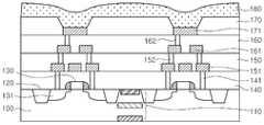
도 3은 실시예에 따른 금속층(180)이 형성된 후의 이미지 센서의 구조를 개략적으로 도시한 측단면도이다.3 is a side cross-sectional view schematically illustrating a structure of an image sensor after a
포토레지스트 패터닝 공정, 이온 주입 공정, 패턴 제거 공정 등을 차례대로 진행하여 반도체 기판, 가령 실리콘 웨이퍼 상태의 반도체 기판(100)에 포토 다이오드(110)를 형성한다.The photoresist patterning process, the ion implantation process, the pattern removal process, and the like are sequentially performed to form the
실시예에 따른 이미지 센서는 적층형 구조를 가지는 이미지 센서인 것으로 하며, 따라서 상기 포토 다이오드(110)는 다수개로서 기판 내부에 수직하게 차례대로 형성된다.The image sensor according to the embodiment may be an image sensor having a stacked structure, and thus, the
가령, 반도체 기판(100)의 광흡수 계수에 따라 밑으로부터 적색 포토 다이오드, 녹색 포토 다이오드, 청색 포토 다이오드의 순서로 형성될 수 있다.For example, it may be formed in the order of a red photodiode, a green photodiode, and a blue photodiode from the bottom according to the light absorption coefficient of the
이와 같은 적층형 이미지 센서는 반도체 기판이 컬러 필터의 기능을 수행하므로 별도의 컬러필터층을 형성할 필요가 없다.The stacked image sensor does not need to form a separate color filter layer because the semiconductor substrate performs a function of a color filter.
다음으로, 상기 반도체 기판(100)의 표면에 트랜치를 형성하고, 트랜치가 매립되도록 하여 기판 전면에 절연층을 형성한 후 기판 표면이 노출되도록 연마 공정을 진행한다. 따라서, 액티브 영역을 정의하는 소자분리영역(120)이 형성된다.Next, a trench is formed on the surface of the
이후, 트랜지스터를 구성하는 게이트(130), 게이트 절연막, 스페이서를 형성하고, 이온주입공정을 통하여 소스/드레인 영역(131)을 형성한다.Thereafter, the
상기 트랜지스터는 다수개로 형성되는데, 포토 다이오드에서 발생된 전기신 호를 축적하는 트랜스퍼 트랜지스터(Tx), 트랜스퍼 트랜지스터(Tx)에 축적된 전기신호를 저장하는 부유 확산(FD; Floating Diffusion)층, 부유 확산층(FD)으로 전원을 인가하는 리셋 트랜지스터(Rx), 부유확산층(FD)에 전기신호가 저장됨에 따라 게이트 전위가 변화되고, 전기신호를 인가하는 억세스 트랜지스터(Ax), 억세스 트랜지스터(Ax)에 의하여 인가된 전기신호를 출력하는 셀렉터 트랜지스터를 포함할 수 있다.A plurality of transistors are formed, a transfer transistor (Tx) that accumulates an electric signal generated in a photodiode, a floating diffusion (FD) layer, and a floating diffusion layer that stores an electrical signal accumulated in the transfer transistor (Tx). As the electrical signal is stored in the reset transistor Rx for applying power to the FD and the floating diffusion layer FD, the gate potential is changed, and the access transistor Ax and the access transistor Ax for applying the electric signal are applied. It may include a selector transistor for outputting an applied electrical signal.
상기 셀렉트 트랜지스터(Sx), 상기 억세스 트랜지스터(Ax), 상기 트랜스퍼 트랜지스터(Tx), 상기 리셋 트랜지스터(Rx)는 실질적으로 동일한 구성을 갖는다.The select transistor Sx, the access transistor Ax, the transfer transistor Tx, and the reset transistor Rx have substantially the same configuration.
다음으로, 트랜지스터를 포함한 상기 반도체 기판(100) 위에 제1 층간절연층(140)을 적층하고, 하부 구조물과 전기적으로 연결되는 컨택 플러그(141)를 상기 제1 층간절연층(140) 상에 형성한다.Next, a first
상기 제1 층간절연층(140) 위에 제2 층간절연층(150)을 형성하고, 상기 제2 층간절연층(150) 상에 상기 컨택 플러그(141)와 연결되는 제1 금속배선(151) 및 제1 비아(152)를 형성한다.A
상기 제2 층간절연층(150) 위에 제3 층간절연층(160)을 형성하고, 상기 제3 층간절연층(160) 상에 상기 제1 비아(152)와 연결되는 제2 금속배선(161) 및 제2 비아(162)를 형성한다.A
이어서, 상기 제3 층간절연층(160) 위에 제4 층간절연층(170)을 형성하고, 상기 제4 층간절연층(170) 상에 상기 제2 비아(162)와 연결되는 제3 금속배선(171)을 형성한다.Subsequently, a fourth
상기 층간절연층들(140, 150, 160, 170)은 가령, 옥사이드 계열의 물질로 형성될 수 있으며, 실시예보다 적거나 많은 층으로 형성될 수 있다.The
실시예에 따른 이미지 센서는 적층형 이미지 센서이므로, 컬러필터층, 평탄화 보호층 등을 필요로 하지 않으며, 패키징 및 프로브 테스트와 같은 후속 공정을 위하여 상기 제3 금속배선(171)을 노출시키기 위한 패터닝 공정 및 식각 공정이 진행된다.Since the image sensor according to the embodiment is a stacked image sensor, it does not require a color filter layer, a planarization protective layer, or the like, and a patterning process for exposing the
이때, 상기 제3 금속배선(171) 위의 상기 제4 층간절연층(170) 상에 단차가 발생된다.In this case, a step is generated on the fourth
실시예에서는, 상기 단차의 문제점을 극복하기 위하여 상기 단차가 매립되도록 하여 제4 층간절연층(170) 위에 금속층(180)을 증착한다.In an embodiment, in order to overcome the problem of the step, the
상기 금속층(180)은 텅스텐(W), 알루미늄(Al), 구리(Cu) 등의 금속을 CVD(Chemical Vapor Deposition) 방법으로 증착함으로써 형성될 수 있으며, 상기 금속층(180)을 형성하기 전에 상기 제4 층간절연층(170) 위에는 배리어금속층(미도시)이 더 형성될 수 있다.The
상기 배리어금속층은 Ti, TiN, Ti/TiN 등의 금속을 이용하여 형성될 수 있다.The barrier metal layer may be formed using a metal such as Ti, TiN, Ti / TiN.
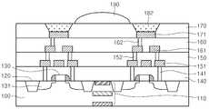
도 4는 실시예에 따른 마이크로 렌즈(190)가 형성된 후의 이미지 센서의 구조를 개략적으로 도시한 측단면도이다.4 is a side cross-sectional view schematically illustrating a structure of an image sensor after the
상기 금속층(180)이 형성되면, 상기 제4 층간절연층(170)의 표면이 드러나도록 상기 금속층(180)을 연마한다.When the
따라서, 상기 단차는 금속매립층(182)에 의하여 제거될 수 있다.Therefore, the step may be removed by the metal buried
이후, 상기 제4 층간절연층(170) 위에 네거티브 포토레지스트층을 형성하고, 패터닝 공정을 통하여 상기 포토 다이오드(110)에 수직하게 대응되는 포토레지스트 패턴을 형성한다.Thereafter, a negative photoresist layer is formed on the fourth
다음으로, 열처리 공정을 진행하여 상기 포토레지스트 패턴을 렌즈 형태로 가공함으로써, 마이크로 렌즈(190)를 형성한다.Next, the
상기 마이크로 렌즈(190)는 상기 포토레지스트 패턴의 식각 공정을 통해서도 형성될 수 있다.The
실시예에 의하면, 마이크로 렌즈(190)를 형성하기 위하여 포토 레지스트 공정을 진행하는 경우 상기 금속매립층(182)이 단자를 보완하므로, 포토 레지스트 끼꺼기가 잔류되는 등의 문제점을 해결할 수 있다.According to the embodiment, when the photoresist process is performed to form the
이상에서 본 발명에 대하여 그 바람직한 실시예를 중심으로 설명하였으나 이는 단지 예시일 뿐 본 발명을 한정하는 것이 아니며, 본 발명이 속하는 분야의 통상의 지식을 가진 자라면 본 발명의 본질적인 특성을 벗어나지 않는 범위에서 이상에 예시되지 않은 여러 가지의 변형과 응용이 가능함을 알 수 있을 것이다. 예를 들어, 본 발명의 실시예에 구체적으로 나타난 각 구성 요소는 변형하여 실시할 수 있는 것이다. 그리고 이러한 변형과 응용에 관계된 차이점들은 첨부된 청구 범위에서 규정하는 본 발명의 범위에 포함되는 것으로 해석되어야 할 것이다.While the present invention has been particularly shown and described with reference to exemplary embodiments thereof, it is to be understood that the invention is not limited to the disclosed exemplary embodiments, but, on the contrary, It will be understood that various modifications and applications other than those described above are possible. For example, each component specifically shown in the embodiments of the present invention can be modified and implemented. And differences relating to such modifications and applications will have to be construed as being included in the scope of the invention defined in the appended claims.
도 1은 적층형 이미지 센서의 구조를 도시한 측단면도.1 is a side cross-sectional view showing the structure of a stacked image sensor.
도 2는 마이크로 렌즈가 형성된 후의 이미지 센서의 형태를 도시한 상면도.Fig. 2 is a top view showing the shape of the image sensor after the microlens is formed.
도 3은 실시예에 따른 금속층이 형성된 후의 이미지 센서의 구조를 개략적으로 도시한 측단면도.3 is a side cross-sectional view schematically showing the structure of an image sensor after the metal layer according to the embodiment is formed;
도 4는 실시예에 따른 마이크로 렌즈가 형성된 후의 이미지 센서의 구조를 개략적으로 도시한 측단면도.4 is a side cross-sectional view schematically showing the structure of an image sensor after the microlens is formed according to the embodiment;
Claims (10)
Translated fromKoreanPriority Applications (1)
| Application Number | Priority Date | Filing Date | Title |
|---|---|---|---|
| KR1020080096029AKR101024739B1 (en) | 2008-09-30 | 2008-09-30 | Image sensor and manufacturing method of image sensor |
Applications Claiming Priority (1)
| Application Number | Priority Date | Filing Date | Title |
|---|---|---|---|
| KR1020080096029AKR101024739B1 (en) | 2008-09-30 | 2008-09-30 | Image sensor and manufacturing method of image sensor |
Publications (2)
| Publication Number | Publication Date |
|---|---|
| KR20100036686A KR20100036686A (en) | 2010-04-08 |
| KR101024739B1true KR101024739B1 (en) | 2011-03-24 |
Family
ID=42214158
Family Applications (1)
| Application Number | Title | Priority Date | Filing Date |
|---|---|---|---|
| KR1020080096029AExpired - Fee RelatedKR101024739B1 (en) | 2008-09-30 | 2008-09-30 | Image sensor and manufacturing method of image sensor |
Country Status (1)
| Country | Link |
|---|---|
| KR (1) | KR101024739B1 (en) |
Citations (3)
| Publication number | Priority date | Publication date | Assignee | Title |
|---|---|---|---|---|
| KR20070071025A (en)* | 2005-12-29 | 2007-07-04 | 매그나칩 반도체 유한회사 | Metal wire manufacturing method of CMOS image sensor |
| JP2007180542A (en) | 2005-12-28 | 2007-07-12 | Dongbu Electronics Co Ltd | Manufacturing method of CMOS image sensor |
| KR100840658B1 (en)* | 2006-08-23 | 2008-06-24 | 동부일렉트로닉스 주식회사 | CMOS image sensor and its manufacturing method |
- 2008
- 2008-09-30KRKR1020080096029Apatent/KR101024739B1/ennot_activeExpired - Fee Related
Patent Citations (3)
| Publication number | Priority date | Publication date | Assignee | Title |
|---|---|---|---|---|
| JP2007180542A (en) | 2005-12-28 | 2007-07-12 | Dongbu Electronics Co Ltd | Manufacturing method of CMOS image sensor |
| KR20070071025A (en)* | 2005-12-29 | 2007-07-04 | 매그나칩 반도체 유한회사 | Metal wire manufacturing method of CMOS image sensor |
| KR100840658B1 (en)* | 2006-08-23 | 2008-06-24 | 동부일렉트로닉스 주식회사 | CMOS image sensor and its manufacturing method |
Also Published As
| Publication number | Publication date |
|---|---|
| KR20100036686A (en) | 2010-04-08 |
Similar Documents
| Publication | Publication Date | Title |
|---|---|---|
| US7541212B2 (en) | Image sensor including an anti-reflection pattern and method of manufacturing the same | |
| US8035143B2 (en) | Semiconductor device and method for manufacturing the same | |
| KR100614793B1 (en) | Image Sensors and Methods of Manufacturing the Same. | |
| US11527564B2 (en) | Manufacturing method of image sensor | |
| US7129108B2 (en) | CMOS image sensor and manufacturing method thereof | |
| US20220310692A1 (en) | Charge release layer to remove charge carriers from dielectric grid structures in image sensors | |
| TW202042383A (en) | Image sensor and method for forming the same | |
| US20090090989A1 (en) | Image Sensor and Method of Manufacturing the Same | |
| KR101024739B1 (en) | Image sensor and manufacturing method of image sensor | |
| KR20090054159A (en) | CMOS image sensor and manufacturing method | |
| KR100958633B1 (en) | Image sensor and its manufacturing method | |
| JP2010118661A (en) | Image sensor and method of manufacturing the image sensor | |
| KR20110068679A (en) | Image sensor and its manufacturing method | |
| KR20060078356A (en) | Manufacturing Method of CMOS Image Sensor | |
| US8003505B2 (en) | Image sensor and method of fabricating the same | |
| US7745251B2 (en) | Method of fabricating CMOS image sensor | |
| KR20100079177A (en) | Cmos image sensor and its fabrication mehod | |
| CN113937117A (en) | image sensing device | |
| KR100897684B1 (en) | Manufacturing Method of Image Sensor | |
| KR100913326B1 (en) | Image sensor and its manufacturing method | |
| KR20100057237A (en) | Image sensor and method for manufacturing the sensor | |
| KR20060037145A (en) | Manufacturing method of CMOS image sensor having a capacitor | |
| KR20100036674A (en) | Image sensor and manufacturing method of image sensor | |
| KR20100078083A (en) | Image sensor, and method for fabricating thereof | |
| KR20100074446A (en) | Manufacturing method of image sensor |
Legal Events
| Date | Code | Title | Description |
|---|---|---|---|
| A201 | Request for examination | ||
| PA0109 | Patent application | St.27 status event code:A-0-1-A10-A12-nap-PA0109 | |
| PA0201 | Request for examination | St.27 status event code:A-1-2-D10-D11-exm-PA0201 | |
| R17-X000 | Change to representative recorded | St.27 status event code:A-3-3-R10-R17-oth-X000 | |
| PG1501 | Laying open of application | St.27 status event code:A-1-1-Q10-Q12-nap-PG1501 | |
| E902 | Notification of reason for refusal | ||
| PE0902 | Notice of grounds for rejection | St.27 status event code:A-1-2-D10-D21-exm-PE0902 | |
| E13-X000 | Pre-grant limitation requested | St.27 status event code:A-2-3-E10-E13-lim-X000 | |
| P11-X000 | Amendment of application requested | St.27 status event code:A-2-2-P10-P11-nap-X000 | |
| P13-X000 | Application amended | St.27 status event code:A-2-2-P10-P13-nap-X000 | |
| E701 | Decision to grant or registration of patent right | ||
| PE0701 | Decision of registration | St.27 status event code:A-1-2-D10-D22-exm-PE0701 | |
| GRNT | Written decision to grant | ||
| PR0701 | Registration of establishment | St.27 status event code:A-2-4-F10-F11-exm-PR0701 | |
| PR1002 | Payment of registration fee | St.27 status event code:A-2-2-U10-U11-oth-PR1002 Fee payment year number:1 | |
| PG1601 | Publication of registration | St.27 status event code:A-4-4-Q10-Q13-nap-PG1601 | |
| LAPS | Lapse due to unpaid annual fee | ||
| PC1903 | Unpaid annual fee | St.27 status event code:A-4-4-U10-U13-oth-PC1903 Not in force date:20140318 Payment event data comment text:Termination Category : DEFAULT_OF_REGISTRATION_FEE | |
| PC1903 | Unpaid annual fee | St.27 status event code:N-4-6-H10-H13-oth-PC1903 Ip right cessation event data comment text:Termination Category : DEFAULT_OF_REGISTRATION_FEE Not in force date:20140318 | |
| P22-X000 | Classification modified | St.27 status event code:A-4-4-P10-P22-nap-X000 | |
| P22-X000 | Classification modified | St.27 status event code:A-4-4-P10-P22-nap-X000 | |
| PN2301 | Change of applicant | St.27 status event code:A-5-5-R10-R13-asn-PN2301 St.27 status event code:A-5-5-R10-R11-asn-PN2301 | |
| R18-X000 | Changes to party contact information recorded | St.27 status event code:A-5-5-R10-R18-oth-X000 | |
| P22-X000 | Classification modified | St.27 status event code:A-4-4-P10-P22-nap-X000 |