KR101023366B1 - Apparatus and method for transmitting / receiving signals in a multiple input multiple output wireless communication system using a beamforming method - Google Patents
Apparatus and method for transmitting / receiving signals in a multiple input multiple output wireless communication system using a beamforming methodDownload PDFInfo
- Publication number
- KR101023366B1 KR101023366B1KR1020040086383AKR20040086383AKR101023366B1KR 101023366 B1KR101023366 B1KR 101023366B1KR 1020040086383 AKR1020040086383 AKR 1020040086383AKR 20040086383 AKR20040086383 AKR 20040086383AKR 101023366 B1KR101023366 B1KR 101023366B1
- Authority
- KR
- South Korea
- Prior art keywords
- receiver
- codes
- signal
- transmitter
- beamforming
- Prior art date
- Legal status (The legal status is an assumption and is not a legal conclusion. Google has not performed a legal analysis and makes no representation as to the accuracy of the status listed.)
- Expired - Lifetime
Links
Images


Classifications
- H—ELECTRICITY
- H04—ELECTRIC COMMUNICATION TECHNIQUE
- H04B—TRANSMISSION
- H04B7/00—Radio transmission systems, i.e. using radiation field
- H04B7/02—Diversity systems; Multi-antenna system, i.e. transmission or reception using multiple antennas
- H04B7/04—Diversity systems; Multi-antenna system, i.e. transmission or reception using multiple antennas using two or more spaced independent antennas
- H04B7/0413—MIMO systems
- H04B7/0426—Power distribution
- H04B7/043—Power distribution using best eigenmode, e.g. beam forming or beam steering
- H—ELECTRICITY
- H04—ELECTRIC COMMUNICATION TECHNIQUE
- H04L—TRANSMISSION OF DIGITAL INFORMATION, e.g. TELEGRAPHIC COMMUNICATION
- H04L1/00—Arrangements for detecting or preventing errors in the information received
- H04L1/02—Arrangements for detecting or preventing errors in the information received by diversity reception
- H04L1/06—Arrangements for detecting or preventing errors in the information received by diversity reception using space diversity
- H04L1/0618—Space-time coding
- H04L1/0637—Properties of the code
- H04L1/0643—Properties of the code block codes
- H—ELECTRICITY
- H04—ELECTRIC COMMUNICATION TECHNIQUE
- H04B—TRANSMISSION
- H04B7/00—Radio transmission systems, i.e. using radiation field
- H04B7/02—Diversity systems; Multi-antenna system, i.e. transmission or reception using multiple antennas
- H04B7/04—Diversity systems; Multi-antenna system, i.e. transmission or reception using multiple antennas using two or more spaced independent antennas
- H04B7/06—Diversity systems; Multi-antenna system, i.e. transmission or reception using multiple antennas using two or more spaced independent antennas at the transmitting station
- H04B7/0613—Diversity systems; Multi-antenna system, i.e. transmission or reception using multiple antennas using two or more spaced independent antennas at the transmitting station using simultaneous transmission
- H04B7/0615—Diversity systems; Multi-antenna system, i.e. transmission or reception using multiple antennas using two or more spaced independent antennas at the transmitting station using simultaneous transmission of weighted versions of same signal
- H04B7/0617—Diversity systems; Multi-antenna system, i.e. transmission or reception using multiple antennas using two or more spaced independent antennas at the transmitting station using simultaneous transmission of weighted versions of same signal for beam forming
- H—ELECTRICITY
- H04—ELECTRIC COMMUNICATION TECHNIQUE
- H04B—TRANSMISSION
- H04B7/00—Radio transmission systems, i.e. using radiation field
- H04B7/02—Diversity systems; Multi-antenna system, i.e. transmission or reception using multiple antennas
- H04B7/04—Diversity systems; Multi-antenna system, i.e. transmission or reception using multiple antennas using two or more spaced independent antennas
- H04B7/08—Diversity systems; Multi-antenna system, i.e. transmission or reception using multiple antennas using two or more spaced independent antennas at the receiving station
- H04B7/0868—Hybrid systems, i.e. switching and combining
- H04B7/088—Hybrid systems, i.e. switching and combining using beam selection
- H—ELECTRICITY
- H04—ELECTRIC COMMUNICATION TECHNIQUE
- H04L—TRANSMISSION OF DIGITAL INFORMATION, e.g. TELEGRAPHIC COMMUNICATION
- H04L1/00—Arrangements for detecting or preventing errors in the information received
- H04L1/02—Arrangements for detecting or preventing errors in the information received by diversity reception
- H04L1/06—Arrangements for detecting or preventing errors in the information received by diversity reception using space diversity
- H04L1/0618—Space-time coding
- H04L1/0625—Transmitter arrangements
Landscapes
- Engineering & Computer Science (AREA)
- Computer Networks & Wireless Communication (AREA)
- Signal Processing (AREA)
- Power Engineering (AREA)
- Radio Transmission System (AREA)
- Mobile Radio Communication Systems (AREA)
Abstract
Translated fromKorean
Description
Translated fromKorean도 1은 일반적인 STBC-빔 포밍 방식을 사용하는 MIMO 무선 통신 시스템의 구조를 개략적으로 도시한 도면1 schematically illustrates the structure of a MIMO wireless communication system using a typical STBC-beam forming scheme;
도 2는 일반적인 빔 스캐닝 방식과 STBC-빔 포밍 방식을 컴바이닝하여 사용하는 MIMO 무선 통신 시스템의 송신기 구조를 개략적으로 도시한 도면FIG. 2 schematically illustrates a transmitter structure of a MIMO wireless communication system using a combination of a general beam scanning method and an STBC-beam forming method.
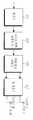
도 3은 본 발명의 실시예에서의 기능을 수행하는, STBC-빔 포밍 방식을 사용하는 MIMO 무선 통신 시스템의 구조를 개략적으로 도시한 도면3 is a schematic diagram illustrating a structure of a MIMO wireless communication system using the STBC-beam forming scheme, which performs a function in an embodiment of the present invention.
도 4는 MIMO 무선 통신 시스템에서 수신 방향에 따른 수신 신호의 에너지 레벨을 도시한 그래프4 is a graph illustrating energy levels of received signals according to reception directions in a MIMO wireless communication system.
도 5는 도 4의 에너지 레벨들중 최대 에너지 레벨을 가지는 빔을 도시한 그래프FIG. 5 is a graph showing a beam having the highest energy level of the energy levels of FIG.
도 6은 도 4의 32개의 빔들중 선택된 빔을 도시한 그래프6 is a graph showing a selected beam of the 32 beams of FIG.
도 7은 MIMO 무선 통신 시스템에서 STBC-빔 포밍 방식을 사용할 경우 선택되 는 최적 빔 및 준최적 빔을 도시한 그래프7 is a graph illustrating an optimal beam and a suboptimal beam selected when using the STBC-beam forming method in a MIMO wireless communication system.
도 8은 본 발명에서 제안하는 빔 포밍 방식과 일반적인 빔 포밍 방식들간의 성능을 비교 도시한 그래프8 is a graph showing a comparison between the performance of the beamforming scheme and the conventional beamforming scheme proposed by the present invention.
도 9는 송신기에서 적용 가능한 빔들 수에 따른 본 발명에서 제안하는 빔 포밍 방식의 성능을 비교 도시한 그래프9 is a graph illustrating the performance of the beamforming scheme proposed by the present invention according to the number of beams applicable to a transmitter
도 10은 본 발명에서 제안하는 빔 포밍 방식과 STBC 방식과 본 발명에서 제안하는 빔 포밍 방식을 컴바이닝한 방식간의 성능을 비교 도시한 그래프
10 is a graph comparing the performance between the beamforming method proposed in the present invention, the STBC method, and the combined method of the beamforming method proposed in the present invention.
본 발명은 다중 입력 다중 출력(MIMO: Multiple Input Multiple Output, 이하 'MIMO'라 칭하기로 한다) 또는 다중 입력 단일 출력 (MISO: Multiple Input Single Output, 이하 'MISO'라 칭하기로 한다.) 무선 통신 시스템(이하 'MIMO / MISO 무선 통신 시스템'이라 칭하기로 한다)에 관한 것으로서, 특히 빔 포밍(beam forming) 방식과 시공간 블록 부호화(STBC: Space Time Block Coding, 이하 'STBC'라 칭하기로 한다) 방식을 사용하는 MIMO/MISO 무선 통신 시스템에서 수신기 성능을 최대화시키는 최적 빔(optimum beam)에 상응하게 빔포밍하여 신호를 송수신하는 장치 및 방법에 관한 것이다.In the present invention, a multiple input multiple output (MIMO) or multiple input single output (MISO) will be referred to as a MISO. (Hereinafter referred to as a 'MIMO / MISO wireless communication system'), in particular, a beam forming method and a space time block coding (STBC) method (hereinafter referred to as 'STBC') The present invention relates to an apparatus and method for beamforming a signal by beamforming corresponding to an optimal beam that maximizes receiver performance in a MIMO / MISO wireless communication system.
차세대 무선 통신 시스템은 패킷 서비스 통신 시스템(packet service communication system) 형태로 발전되어 왔으며, 패킷 서비스 통신 시스템은 버스트(burst)한 패킷 데이터(packet data)를 다수의 사용자 단말기(user terminal)들로 전송하는 시스템으로서, 대용량 데이터 전송에 적합하도록 설계되어 왔다. 상기 패킷 서비스 통신 시스템은 고속 패킷 서비스를 위해 발전해나가고 있으며, 상기 고속 패킷 서비스를 제공하기 위해서는 평균 전송량(average throughput)뿐 아니라 최대 전송량(peak throughput)을 최적화하여 음성 서비스와 같은 서킷(circuit) 데이터 뿐만 아니라 패킷 데이터 전송을 원활하게 한다.The next generation wireless communication system has been developed in the form of a packet service communication system, and the packet service communication system transmits bursted packet data to a plurality of user terminals. As a system, it has been designed for large data transfer. The packet service communication system is evolving for high speed packet service, and in order to provide the high speed packet service, not only average throughput but also peak throughput are optimized to provide circuit data such as voice service. Rather, it facilitates packet data transmission.
또한, 상기 고속 패킷 서비스를 위해서는 데이터 레이트(data rate)를 증가시키고 송신 신뢰성을 향상시키는 것이 중요한 요인으로 작용하는데, 상기 데이터 레이트를 증가시키고 송신 신뢰성을 향상시키는 방식으로 활발하게 연구되고 있는 방식이 다중 안테나(multiple antenna) 방식이다. 상기 다중 안테나 방식은 공간 영역(space domain)을 활용하므로 주파수 영역의 대역폭 자원의 한계를 극복하는 방식이다.In addition, for the high-speed packet service, increasing the data rate and improving the transmission reliability are important factors, and a method that is being actively studied as a method of increasing the data rate and improving the transmission reliability is multiple. It is a multiple antenna method. Since the multi-antenna scheme uses a space domain, the multi-antenna scheme overcomes the limitation of bandwidth resources in the frequency domain.
한편, 스마트 안테나(smart antenna) 방식은 수신 안테나들간에 상관이 존재할 때 수신측에서 미리 설정되어 있는 수신 방향(DOA: Direction Of Arrival)에 상응하게 신호를 수신하여 빔 포밍(beam forming)을 수행하는 방식이다. 상기 스마트 안테나 방식은 수신 빔 포밍 방식으로서, 상기 스마트 안테나 방식은 상기 사용자 단말기보다는 기지국(BS: Base Station)에서 업링크(uplink) 신호, 즉 사용자 단말기로부터 상기 기지국으로 송신한 신호를 수신하는데 적합한 방식이다.In the smart antenna scheme, when a correlation exists between reception antennas, a signal is received by a signal corresponding to a reception direction (DOA) preset in the reception side to perform beamforming. That's the way. The smart antenna scheme is a reception beamforming scheme, and the smart antenna scheme is a scheme suitable for receiving an uplink signal from a base station (BS), that is, a signal transmitted from a user terminal to the base station, rather than the user terminal. to be.
즉, 상기 사용자 단말기의 경우 하드웨어 최소화 측면이나 혹은 제조 단가 등의 측면 등과 같은 여러 가지 측면에서 다수의 수신 안테나들을 구비한다는 것은 난이하지만, 이와는 반대로 상기 기지국의 경우 상기 하드웨어 최소화 측면이나 혹은 제조 단가 등의 측면 등에서 상기 사용자 단말기에 비해 다수의 수신 안테나들을 구비하는 것이 용이하기 때문에 상기 스마트 안테나 방식은 상기 기지국에 적용하는 것이 바람직하게 되는 것이다.That is, in the case of the user terminal, it is difficult to provide a plurality of receiving antennas in various aspects such as hardware minimization side or manufacturing unit cost, etc. It is preferable to apply the smart antenna scheme to the base station because it is easier to have a plurality of receiving antennas than the user terminal from the side.
한편, 신호대 간섭 잡음비(SINR: Signal to Interference and Noise Ratio, 이하 'SINR'이라 칭하기로 한다)를 최대화시키는 측면에서 최적인 방식으로는 최소 평균 제곱 에러(MMSE: Minimum Mean Square Error, 이하 'MMSE'라 칭하기로 한다) 방식이 존재한다. 또한, 최대비 컴바이닝(MRC: Maximum Ratio Combining, 이하 'MRC'라 칭하기로 한다) 방식은 신호대 잡음비(SNR: Signal to Noise Ratio, 이하 'SNR'이라 칭하기로 한다)를 최대화시키는 측면에서 최적인 방식이다.On the other hand, the optimal method in terms of maximizing the Signal to Interference and Noise Ratio (SINR) (hereinafter referred to as 'SINR') is the minimum mean square error (MMSE). There is a method). In addition, the Maximum Ratio Combining (MRC) method is optimal in terms of maximizing the Signal to Noise Ratio (SNR). That's the way.
또한, 송신 빔 포밍 방식은 송신기측에서 다수개의 송신 안테나들을 사용하여 신호를 송신할 때, 즉 기지국에서 사용자 단말기들로 다운링크(downlink) 신호를 송신할 때 송신 신뢰성을 향상시키기 위해 고려되고 있는 방식이다. 상기 MRC 방식을 기반으로 하는 송신 빔 포밍 방식을 사용할 경우 SNR 측면에서 최적이 되며, 채널의 중요 아이겐 벡터(principal eigen vector)에 의해 생성된 선-왜곡(pre-distortion) 필터와 동일한 효과를 가지게 된다.In addition, the transmission beamforming scheme is considered to improve transmission reliability when transmitting a signal using a plurality of transmission antennas at the transmitter side, that is, when transmitting a downlink signal from a base station to user terminals. to be. The transmission beamforming method based on the MRC method is optimal in terms of SNR, and has the same effect as the pre-distortion filter generated by the principal eigen vector of the channel. .
상기 송신 빔 포밍 방식은 수신기측에서 정확한 채널 추정을 수행하고, 상기 수신기측에서 송신기측으로 피드백하는 신호에 에러가 발생하지 않는다는 가정하에서만 다이버시티 이득과 어레이 이득을 제공하며, 데이터 송신의 신뢰성을 극대화 시키는 것이 가능하다. 그러나, 상기 송신 빔 포밍 방식은 상기 수신기측에서 정확한 채널 추정을 수행한다는 가정을 만족한다고 하더라도 송신기 또는 수신기측에서 복잡도가 높은 아이겐-분석(eigen-decomposition, 이하 'eigen-decomposition'라 칭하기로 한다)을 수행해야만 하며, 수신기로부터 채널 정보를 송신기로 피드백하여야만 한다는 문제점을 가진다.The transmit beamforming method performs accurate channel estimation at the receiver side, provides diversity gain and array gain only under the assumption that no error occurs in a signal fed back from the receiver side to the transmitter side, and maximizes reliability of data transmission. It is possible to let. However, even if the transmission beamforming scheme satisfies the assumption that the receiver performs accurate channel estimation, a high complexity eigen-decomposition (hereinafter, referred to as 'eigen-decomposition') at the transmitter or receiver side will be described. And must feed back channel information from the receiver to the transmitter.
한편, 채널 상호성(channel reciprocity)은 시분할 듀플렉스(TDD: Time Division Duplex, 이하 'TDD'라 칭하기로 한다) 통신 시스템에서 채널 상태 정보의 피드백을 방지하기 위해 사용되는 방법으로서 아이겐-빔 포밍(eigen-beam forming) 방식과 방향성-빔 포밍(directional-beam forming) 방식을 사용할 경우에 적용된다. 즉, 상기 TDD 통신 시스템과 같이 다운링크와 업링크의 채널 상태가 동일하다고 가정하는 것이 가능할 경우에는, 즉 상기 다운링크와 업링크가 채널 상호성을 가질 경우에는 다운링크 혹은 업링크 중 어느 한 링크의 채널 상태만을 가지고도 나머지 다른 한 링크의 채널 상태를 유추하는 것이 가능하므로 상기 아이겐-빔 포밍 방식과 방향성-빔 포밍 방식을 사용함에 있어 상기 채널 상태 정보 피드백으로 인한 복잡도를 최소화시킬 수 있는 것이다.Meanwhile, channel reciprocity is a method used to prevent feedback of channel state information in a time division duplex (TDD) communication system. It is applied to the case of using the beam forming method and the directional-beam forming method. That is, when it is possible to assume that the channel states of the downlink and the uplink are the same as in the TDD communication system, that is, when the downlink and the uplink have channel interactivity, the downlink or the uplink may be one of the downlink or the uplink. Since the channel state of the other link can be inferred only by using the channel state, the complexity due to the feedback of the channel state information can be minimized in using the eigen-beam forming method and the directional-beam forming method.
그러나, 상기 TDD 통신 시스템에서도 송신과 수신 디바이스 특성이 서로 다르기 때문에 상기 채널 상호성이 무너지게 되고, 따라서 상기 채널 상태를 고려하기 위한 효율적인 교정(calibration)이 필요하다.However, even in the TDD communication system, since the characteristics of the transmitting and receiving devices are different from each other, the channel interoperability is broken, and thus an efficient calibration is required to consider the channel condition.
한편, 상기 STBC 방식은 분산 채널(rich scattering channel) 환경을 고려한 송신 방식으로서, 상기 STBC 방식은 송신기측에서 2개의 송신 안테나들을 사용하는 경우를 고려한다. 상기 STBC 방식은 이미 잘 알려진바 있으므로 여기서는 그 상세한 설명을 생략하기로 한다(S. M. Alamouti, "A simple transmit diversity technique for wireless communications," IEEE Journal of Selected Areas in Communications, Vol. 16, pp 1451-1458, Oct. 1988).Meanwhile, the STBC scheme is a transmission scheme considering a rich scattering channel environment. The STBC scheme considers a case where two transmitter antennas are used at the transmitter side. Since the STBC scheme is well known, its detailed description will be omitted here (SM Alamouti, "A simple transmit diversity technique for wireless communications," IEEE Journal of Selected Areas in Communications, Vol. 16, pp 1451-1458, Oct. 1988).
상기 STBC 방식은 송신기측에서 비교적 간단하게 적용할 수 있으며, 수신기 구조 역시 간단하게 구현할 수 있어 3GPP(3rd Generation Partnership Project) 표준에서는 이미 옵션 규격으로 채택된바 있다. 그러나, 상기 STBC 방식은 송신 안테나들간의 상관이 매우 중요한 요소로 작용하기 때문에 그 성능에 제한적이라는 문제점을 가진다.The STBC scheme is relatively simple to be applied on the transmitter side, and the receiver structure can be simply implemented. Therefore, the 3rd Generation Partnership Project (3GPP) standard has already been adopted as an optional standard. However, the STBC method has a problem in that its performance is limited because the correlation between transmitting antennas is a very important factor.
한편, 채널 예측의 불완전성과 송신기측으로의 불완전한 정보 피드백을 보상하기 위해 상기 STBC 방식과 빔포밍 방식을 컴바이닝한 방식인 STBC-빔 포밍 방식이 제안된 바 있다(G. Jongren and M. Skoglund, 'Combining beamforming and orthogonal space-time block coding,'IEEE Trans. Information Theory, Vol. 48, No.3, pp. 611-627, March 200). 그러면 여기서 도 1을 참조하여 상기 STBC-빔 포밍 방식에 대해서 설명하기로 한다.On the other hand, the STBC-beam forming method, which combines the STBC method and the beamforming method, has been proposed to compensate for incomplete channel prediction and incomplete information feedback to the transmitter (G. Jongren and M. Skoglund, ' Combining beamforming and orthogonal space-time block coding, 'IEEE Trans.Information Theory, Vol. 48, No. 3, pp. 611-627, March 200). Next, the STBC-beam forming method will be described with reference to FIG. 1.
상기 도 1은 일반적인 STBC-빔 포밍 방식을 사용하는 MIMO 무선 통신 시스템의 구조를 개략적으로 도시한 도면이다.1 is a diagram schematically illustrating a structure of a MIMO wireless communication system using a general STBC-beam forming scheme.
상기 도 1을 참조하면, 상기 MIMO 무선 통신 시스템은 송신기(100)와 수신기(150)로 구성된다. 상기 송신기(100)는 시공간 블록 부호화기(space-time block encoder)(111)와, 빔 포밍기(beam former)(113)와, 복호화기(decoder)(115)와, 다 수의 송신 안테나(Tx. ANT)들(117-1, ... , 117-M)로 구성되며, 상기 수신기(150)는 다수의 수신 안테나(Rx. ANT)들(151-1, ... , 151-N)과, 수신 처리기(153)와, 부호화기(155)로 구성된다.Referring to FIG. 1, the MIMO wireless communication system includes a
먼저, 상기 송신기(100)에서 수신기(150)로 송신할 데이터가 발생하면, 상기 데이터는 상기 시공간 블록 부호화기(111)로 전달되고, 상기 시공간 블록 부호화기(111)는 상기 데이터를 STBC 방식으로 부호화한 후 상기 빔 포밍기(113)로 출력한다. 상기 빔 포밍기(113)는 상기 시공간 블록 부호화기(111)에서 출력한 신호를 입력하여 상기 복호화기(115)에서 출력하는 빔 정보에 상응하는 빔으로 빔 포밍을 수행한 후 상기 송신 안테나들(117-1, ... , 117-M)을 통해 상기 수신기(150)로 송신한다. 상기 복호화기(115)는 상기 수신기(150)로부터 피드백되는 빔 정보를 복호화한 후 상기 빔 포밍기(113)로 출력하며, 상기 피드백되는 빔 정보는 양자화 정보로서 이는 하기에서 구체적으로 설명할 것이므로 여기서는 그 상세한 설명을 생략하기로 한다. 또한, 상기 수신기(150)로부터 상기 복호화기(115)로의 신호 수신 경로에 대해서는 별도로 도시하지 않았음에 유의하여야만 한다.First, when data to be transmitted from the
한편, 상기 송신기(100)에서 송신한 신호는 다중 경로 채널(multipath channel)을 통한 후 백색 가산성 가우시안 잡음(AWGN: Additive White Gaussian Noise) 등과 같은 잡음이 가산된 형태로 상기 수신기(150)의 수신 안테나들(151-1, ... , 151-N)을 통해 수신된다. 상기 수신 안테나들(151-1, ... , 151-N)을 통해 수신된 신호는 상기 수신 처리기(153)로 전달되고, 상기 수신 처리기(153)는 상기 수신 안테나들(151-1, ... , 151-N)을 통해 수신된 신호를 수신 신호 처리하고, 상 기 수신 신호 처리 결과 획득된 채널 정보를 상기 부호화기(155)로 출력한다.On the other hand, the signal transmitted from the
상기 부호화기(155)는 상기 수신 처리기(153)에서 출력한 채널 정보를 미리 설정되어 있는 양자화 방식으로 양자화한 후 상기 송신기(100)로 송신하도록 한다. 또한, 상기 부호화기(155)에서 상기 송신기(100)로의 신호 송신 경로에 대해서는 별도로 도시하지 않았음에 유의하여야만 한다.The
상기 도 1에서 설명한 바와 같은 STBC-빔 포밍 방식이 제안된 후 상기 STBC 방식과 빔 포밍 방식을 개선시켜 상기 STBC-빔 포밍 방식의 성능 개선을 위한 연구들이 활발하게 진행되었다. 그 결과 상기 시공간 블록 부호화기를 위한 최적 선 부호화기(pre-encoder)가 제안되었으며, 상기 최적 선 부호화기는 직교(orthogonal) 시공간 블록 부호화기를 위한 아이겐-빔 포밍기로 구현될 수 있음이 증명된 바 있다(H. Sampath and A. Paulraj, "Linear precoding for space-time coded systems with known fading correlations," IEEE Communications Letters, Vol. 6, No 6, pp. 239-241, June 2002).After the STBC-beam forming method as described in FIG. 1 is proposed, studies have been actively conducted to improve the performance of the STBC-beam forming method by improving the STBC method and the beam forming method. As a result, an optimal pre-encoder for the space-time block coder has been proposed, and it has been proved that the optimal line coder can be implemented as an eigen-beam forming machine for an orthogonal space-time block coder. Sampath and A. Paulraj, "Linear precoding for space-time coded systems with known fading correlations," IEEE Communications Letters, Vol. 6, No 6, pp. 239-241, June 2002).
상기 STBC-빔 포밍 방식에 대한 활발한 연구가 진행되었음에도 불구하고 상기 STBC-빔 포밍 방식을 사용하기 위해서는 송신기는 여전히 수신기로부터 채널 정보를 피드백 받아야 할 뿐 아니라 채널 정보에 대한 아이겐 분석(eigen-analysis)을 필요로 한다.Despite the active research on the STBC-beam forming method, the transmitter still needs to feed back channel information from the receiver to perform the eigen-analysis of the channel information in order to use the STBC-beam forming method. in need.
그러면 여기서 도 2를 참조하여 상기 빔 스캐닝 방식과 STBC-빔 포밍 방식을 컴바이닝한 방식에 대해서 설명하기로 한다.Next, a method of combining the beam scanning method and the STBC-beam forming method will be described with reference to FIG. 2.
상기 도 2는 일반적인 빔 스캐닝 방식과 STBC-빔 포밍 방식을 컴바이닝하여 사용하는 MIMO 무선 통신 시스템의 송신기 구조를 개략적으로 도시한 도면이다.FIG. 2 is a diagram schematically illustrating a transmitter structure of a MIMO wireless communication system using a combination of a general beam scanning method and an STBC-beam forming method.
상기 도 2를 참조하면, 상기 MIMO 무선 통신 시스템의 송신기는 변조기(modulator)(211)와, 시공간 블록 부호화기(213)와, 직렬/병렬 변환기(serial to parallel converter)(215)와, 빔 포밍기(217)와, 다수의 송신 안테나들(219-1, ... , 219-M)로 구성된다.Referring to FIG. 2, a transmitter of the MIMO wireless communication system includes a
먼저, 상기 송신기에서 수신기로 송신할 데이터가 발생하면, 상기 데이터는 상기 변조기(211)로 전달되고, 상기 변조기(211)는 상기 데이터를 미리 설정되어 있는 변조 방식으로 변조한 후 상기 시공간 블록 부호화기(213)로 출력한다. 상기 시공간 블록 부호화기(213)는 상기 변조기(211)에서 출력한 신호를 STBC 방식으로 부호화한 후 상기 직렬/병렬 변환기(215)로 출력한다. 상기 직렬/병렬 변환기(215)는 상기 시공간 블록 부호화기(213)에서 출력한 신호를 병렬 변환한 후 상기 빔 포밍기(217)로 출력한다. 상기 빔 포밍기(217)는 상기 직렬/병렬 변환기(215)에서 출력한 신호를 입력하여 미리 설정되어 있는 빔 정보에 상응하는 빔으로 빔 포밍을 수행한 후 상기 송신 안테나들(219-1, ... , 219-M)을 통해 상기 수신기로 송신한다. 여기서, 상기 빔 정보는 상기 빔 스캐닝 방식을 적용한, 즉 상기 송신기측에서 수신된 신호의 채널 공간 이득 패턴(GSGP: Channel Spatial Gain Pattern)을 고려한 정보로서 미리 설정한 임계값 이상의 에너지를 가지는 빔들을 고려하여 생성된다.First, when data to be transmitted from the transmitter to the receiver is generated, the data is transferred to the
그러나, 상기 빔 스캐닝 방식을 함께 사용한다고 하더라도 상기 STBC-빔 포밍 방식은 임계값 이상의 에너지를 가지는 여러 빔들로부터 불필요한 간섭 신호에 대한 빔을 제외시켜야 하고 상기 채널 상호성과 같은 비현실적인 가정들이 만족 될 경우에만 우수한 성능을 보장받는다는 문제점을 가지고 있다.
However, even when the beam scanning method is used together, the STBC-beam forming method should exclude a beam for unnecessary interference signals from several beams having energy above a threshold value and is excellent only when unrealistic assumptions such as the channel interactivity are satisfied. The problem is that performance is guaranteed.
따라서, 본 발명의 목적은 빔 포밍 방식과 STBC 방식을 사용하는 MIMO/MISO 무선 통신 시스템에서 수신기 성능을 최대화시키는 최적 빔에 상응하게 빔포밍하여 신호를 송수신하는 장치 및 방법을 제공함에 있다.Accordingly, an object of the present invention is to provide an apparatus and method for beamforming and transmitting a signal corresponding to an optimal beam for maximizing receiver performance in a MIMO / MISO wireless communication system using a beamforming scheme and an STBC scheme.
본 발명의 다른 목적은 빔 포밍 방식과 STBC 방식을 사용하는 MIMO 무선 통신 시스템에서 방향성을 갖는 최적 빔과 준최적 빔(이하에서는 최적 조건인'방향성를 갖는'을 생략하여 최적 빔과 준최적 빔을 사용한다)을 사용하여 신호를 송수신하여 연산 복잡도를 최소화시키는 장치 및 방법을 제공함에 있다.Another object of the present invention is to use an optimal beam and a suboptimal beam by omitting the optimal beam having a directivity and a suboptimal beam in the MIMO wireless communication system using the beamforming method and the STBC method. The present invention provides an apparatus and method for minimizing computational complexity by transmitting and receiving signals.
상기한 목적들을 달성하기 위한 본 발명의 장치는; 다중 입력 다중 출력 또는 다중 입력 단일 출력 무선 통신 시스템의 송신기에서 빔 포밍 방식을 사용하여 신호를 송신하는 장치에 있어서, 기준 신호를 상기 송신기에서 사용 가능한 빔들 각각에 미리 설정되어 있는 코드들 각각을 일대일로 매핑시켜 빔포밍한 후 수신기로 송신하고, 소정 제어에 따라 제공되는 최적 빔 정보에 상응한 빔으로 데이터 신호를 빔 포밍하여 상기 수신기로 송신하는 빔 포밍기와, 상기 수신기로부터 신호를 수신하면 상기 수신 신호를 복호화하여 상기 빔들중 수신 성능을 최대화하는 최적 빔 정보를 상기 빔 포밍기로 제공하는 복호화기를 포함함을 특징으로 한다.The apparatus of the present invention for achieving the above objects; An apparatus for transmitting a signal using a beamforming scheme in a transmitter of a multiple input multiple output or multiple input single output wireless communication system, the reference signal being one-to-one with each of the codes preset in each of the beams available in the transmitter. A beamformer for mapping and beamforming and transmitting to a receiver, and a beamformer for beamforming a data signal with a beam corresponding to optimal beam information provided according to a predetermined control, and transmitting the signal to the receiver; And a decoder which provides optimal beam information for maximizing reception performance among the beams to the beamformer by decoding.
상기한 목적들을 달성하기 위한 본 발명의 다른 장치는; 다중 입력 다중 출 력 또는 다중 입력 단일 출력 무선 통신 시스템의 송신기에서 빔 포밍 방식과 시공간 블록 부호화 방식을 사용하여 신호를 송신하는 장치에 있어서, 송신할 데이터 신호가 발생하면, 상기 데이터 신호를 시공간 블록 부호화 방식으로 부호화하는 시공간 블록 부호화기와, 기준 신호를 상기 송신기에서 사용 가능한 빔들 각각에 미리 설정되어 있는 코드들 각각을 일대일로 매핑시켜 빔포밍한 후 수신기로 송신하고, 소정 제어에 따라 제공되는 최적 빔 정보 및 준최적 빔 정보에 상응하는 빔들로 상기 시공간 블록 부호화된 데이터 신호를 빔 포밍하여 상기 수신기로 송신하는 빔 포밍기와, 상기 수신기로부터 신호를 수신하면 상기 수신 신호를 복호화하여 상기 빔들중 수신 성능을 최대화하는 최적 빔 및 준최적 빔 정보를 상기 빔 포밍기로 제공하는 복호화기를 포함함을 특징으로 한다.Another apparatus of the present invention for achieving the above objects; An apparatus for transmitting a signal by using a beamforming method and a space-time block coding method in a transmitter of a multi-input multiple output or multi-input single output wireless communication system, wherein, when a data signal to be transmitted is generated, the data signal is space-time block encoded. A space-time block coder that encodes by a method, and maps a reference signal to each of the beams available in the transmitter in a one-to-one manner, beamforms the beamforms, and transmits them to a receiver, and provides optimal beam information according to a predetermined control And a beamformer for beamforming the space-time block-coded data signal with beams corresponding to sub-optimal beam information to the receiver, and when receiving the signal from the receiver, decode the received signal to maximize reception performance among the beams. Beamforming the optimal beam and suboptimal beam information It characterized in that it comprises a decoder provided by the group.
상기한 목적들을 달성하기 위한 본 발명의 또 다른 장치는; 다중 입력 다중 출력 또는 다중 입력 단일 출력 무선 통신 시스템의 수신기에서 빔 포밍 방식을 사용하여 송신한 신호를 수신하는 장치에 있어서, 기준 신호가 수신되면, 상기 기준 신호를 송신기에서 사용 가능한 빔들 각각에 일대일로 미리 매핑되어 있는 코드들 각각으로 상관하고, 상기 코드들 각각에 대해 상관한 상관값들중 최대 상관값을 가지는 코드에 매핑되어 있는 빔을 최적 빔으로 선택하는 수신 처리기와, 상기 선택된 최적 빔을 나타내는 정보를 상기 송신기로 피드백하는 부호화기를 포함함을 특징으로 한다.Another apparatus of the present invention for achieving the above objects is; 1. An apparatus for receiving a signal transmitted using a beamforming scheme at a receiver of a multiple input multiple output or multiple input single output wireless communication system, the reference signal being received one to one on each of the beams available at the transmitter. A reception processor for correlating to codes mapped in advance and selecting a beam mapped to a code having a maximum correlation value among correlation values correlated for each of the codes as an optimal beam, and indicating the selected optimal beam And an encoder for feeding back information to the transmitter.
상기한 목적들을 달성하기 위한 본 발명의 또 다른 장치는; 다중 입력 다중 출력 또는 다중 입력 단일 출력 무선 통신 시스템의 수신기에서 빔 포밍 방식과 시 공간 블록 부호화 방식을 사용하여 송신한 신호를 수신하는 장치에 있어서, 기준 신호가 수신되면, 상기 기준 신호를 송신기에서 사용 가능한 빔들 각각에 일대일로 미리 매핑되어 있는 코드들 각각으로 상관하고, 상기 코드들 각각에 대해 상관한 상관값들중 최대 상관값을 가지는 제1코드에 매핑되어 있는 빔을 최적 빔으로 선택하고, 상기 최대 상관값을 제외한 상관값들중 피크 상관값을 나타내며, 상기 제1코드와 미리 설정한 임계 상관값 미만의 상관값을 가지는 제2 코드에 매핑되는 빔을 준최적 빔으로 선택하는 수신 처리기와, 상기 선택된 최적 빔 및 준최적 빔을 나타내는 정보를 상기 송신기로 피드백하는 부호화기를 포함함을 특징으로 한다.Another apparatus of the present invention for achieving the above objects is; An apparatus for receiving a signal transmitted using a beamforming scheme and a space-time block coding scheme in a receiver of a multiple input multiple output or multiple input single output wireless communication system, wherein the reference signal is used by the transmitter when a reference signal is received. Correlates to each of the codes that are previously mapped to each of the possible beams one-to-one, and selects a beam mapped to the first code having the maximum correlation value among the correlation values correlated for each of the codes as the optimal beam, and A reception processor which represents a peak correlation value among the correlation values excluding the maximum correlation value, and selects a beam mapped to the second code having a correlation value less than a predetermined threshold correlation value as a suboptimal beam; And an encoder for feeding back information indicating the selected optimal beam and the suboptimal beam to the transmitter.
상기한 목적들을 달성하기 위한 본 발명의 방법은; 다중 입력 다중 출력 또는 다중 입력 단일 출력 무선 통신 시스템의 송신기에서 빔 포밍 방식을 사용하여 신호를 송신하는 방법에 있어서, 기준 신호를 상기 송신기에서 사용 가능한 빔들 각각에 미리 설정되어 있는 코드들 각각을 일대일로 매핑시켜 빔포밍한 후 수신기로 송신하는 과정과, 이후 상기 수신기로부터 상기 빔들중 수신 성능을 최대화하는 최적 빔을 나타내는 정보를 수신하면, 상기 최적 빔 정보에 상응한 빔으로 데이터 신호를 빔 포밍하여 상기 수신기로 송신하는 과정을 포함함을 특징으로 하는 한다.The method of the present invention for achieving the above objects; A method of transmitting a signal using a beamforming scheme in a transmitter of a multi-input multi-output or multi-input single-output wireless communication system, wherein the reference signal is one-to-one with each of the codes preset in each of the beams available in the transmitter. After mapping and beamforming and transmitting to the receiver, and after receiving information indicating the optimal beam among the beams to maximize the reception performance, the data signal is beamformed into a beam corresponding to the optimal beam information. It characterized in that it comprises the step of transmitting to the receiver.
상기한 목적들을 달성하기 위한 본 발명의 다른 방법은; 다중 입력 다중 출력 또는 다중 입력 단일 출력 무선 통신 시스템의 송신기에서 빔 포밍 방식과 시공간 블록 부호화 방식을 사용하여 신호를 송신하는 방법에 있어서, 기준 신호를 상기 송신기에서 사용 가능한 빔들 각각에 미리 설정되어 있는 코드들 각각을 일대일로 매핑시켜 빔포밍한 후 수신기로 송신하는 과정과, 상기 수신기로부터 상기 빔들 중 수신 성능을 최대화하는 최적 빔 및 준최적 빔 정보를 수신하는 과정과, 이후 송신할 데이터 신호가 발생하면, 상기 데이터 신호를 시공간 블록 부호화 방식으로 부호화한 후 상기 최적 빔 및 준최적 빔 정보에 상응한 빔들로 빔 포밍하여 상기 수신기로 송신하는 과정을 포함함을 특징으로 한다.Another method of the present invention for achieving the above objects is; A method of transmitting a signal using a beamforming scheme and a space-time block coding scheme in a transmitter of a multiple input multiple output or multiple input single output wireless communication system, the method in which a reference signal is preset to each of the beams available in the transmitter Mapping each of the beams one-to-one to beamforming and transmitting to the receiver, receiving optimal beam and sub-optimal beam information for maximizing reception performance among the beams from the receiver, and then generating a data signal to be transmitted. And encoding the data signal by using a space-time block encoding method and beamforming the beams into beams corresponding to the optimal beam and sub-optimal beam information and transmitting the beams to the receiver.
상기한 목적들을 달성하기 위한 본 발명의 또 다른 방법은; 다중 입력 다중 출력 또는 다중 입력 단일 출력 무선 통신 시스템의 수신기에서 빔 포밍 방식을 사용하여 송신한 신호를 수신하는 방법에 있어서, 기준 신호가 수신되면, 상기 기준 신호를 송신기에서 사용 가능한 빔들 각각에 일대일로 미리 매핑되어 있는 코드들 각각으로 상관하는 과정과, 상기 코드들 각각에 대해 상관한 상관값들중 최대 상관값을 가지는 코드에 매핑되어 있는 빔을 최적 빔으로 선택하고, 상기 최적 빔을 나타내는 정보를 상기 송신기로 피드백하는 과정을 포함함을 특징으로 한다.Another method of the present invention for achieving the above objects is; A method for receiving a signal transmitted using a beamforming scheme at a receiver of a multiple input multiple output or multiple input single output wireless communication system, wherein when a reference signal is received, the reference signal is one-to-one to each of the beams available at the transmitter. Correlating to codes mapped in advance, selecting a beam mapped to a code having a maximum correlation value among correlation values correlated for each of the codes as an optimal beam, and providing information indicating the optimal beam. And feeding back to the transmitter.
상기한 목적들을 달성하기 위한 본 발명의 또 다른 방법은; 다중 입력 다중 출력 또는 다중 입력 단일 출력 무선 통신 시스템의 수신기에서 빔 포밍 방식과 시공간 블록 부호화 방식을 사용하여 송신한 신호를 수신하는 방법에 있어서, 기준 신호가 수신되면, 상기 기준 신호를 송신기에서 사용 가능한 빔들 각각에 일대일로 미리 매핑되어 있는 코드들 각각으로 상관하는 과정과, 상기 코드들 각각에 대해 상관한 상관값들중 최대 상관값을 가지는 제1코드에 매핑되어 있는 빔을 최적 빔으로 선택하고, 상기 최대 상관값을 제외한 상관값들중 피크 상관값을 나타내며, 상기 제1코드와 미리 설정한 임계 상관값 미만의 상관값을 가지는 제2 코드에 매핑되는 빔을 준최적 빔으로 선택하고, 상기 최적 빔 및 준최적 빔을 나타내는 정보를 상기 송신기로 피드백하는 과정을 포함함을 특징으로 한다.
Another method of the present invention for achieving the above objects is; A method for receiving a signal transmitted using a beamforming method and a space-time block coding method in a receiver of a multi-input multi-output or multi-input single-output wireless communication system, the reference signal being available to the transmitter when a reference signal is received. Correlating to each of the codes pre-mapped one-to-one to each of the beams, selecting a beam mapped to the first code having the maximum correlation value among the correlation values correlated for each of the codes as an optimal beam, Among the correlation values excluding the maximum correlation value, a peak correlation value is represented, and a beam mapped to the second code having a correlation value less than a predetermined threshold correlation value is selected as a suboptimal beam, and the optimal And feeding back information indicating the beam and the suboptimal beam to the transmitter.
이하, 본 발명에 따른 바람직한 실시예를 첨부한 도면을 참조하여 상세히 설명한다. 하기의 설명에서는 본 발명에 따른 동작을 이해하는데 필요한 부분만이 설명되며 그 이외 부분의 설명은 본 발명의 요지를 흩트리지 않도록 생략될 것이라는 것을 유의하여야 한다.Hereinafter, exemplary embodiments of the present invention will be described in detail with reference to the accompanying drawings. It should be noted that in the following description, only parts necessary for understanding the operation according to the present invention will be described, and descriptions of other parts will be omitted so as not to distract from the gist of the present invention.
본 발명은 다중 입력 다중 출력(MIMO: Multiple Input Multiple Output, 이하 'MIMO'라 칭하기로 한다) 또는 다중 입력 단일 출력 (MISO: Multiple Input Single Output, 이하 'MISO'라 칭하기로 한다) 방식을 사용하는 무선 통신 시스템(이하 'MIMO/MISO 무선 통신 시스템' 이라 칭하기로 한다)에서 빔 포밍(beam forming) 방식과 시공간 블록 부호화(STBC: Space Time Block Coding) 방식을 사용할 경우 송신기, 일 예로 기지국(BS: base Station)에서 수신기, 일 예로 사용자 단말기(user terminal)로부터 피드백되는 최적 빔(optimum beam) 정보에 상응하는 빔을 사용하여 상기 사용자 단말기로 송신할 신호를 빔 포밍하여 송신하는 방안을 제안한다. 특히, 본 발명은 상기 기지국에서 사용하는 모든 빔들 각각에 직교 코드(orthogonal code)들을 일대일로 매핑하여 송신함으로써 상기 사용자 단말기에서 상기 사용자 단말기 자신이 신호를 수신함에 있어 최적인 빔을 선택하도록 하여 수신 성능을 최대화시킨다. 또한, 본 발명은 상기 빔 포밍 방식과 STBC 방식을 컴바이닝한 방식인 STBC-빔 포밍 방식을 사용함에 있어 상기 최적 빔 및 준최적 빔 (sub-optimum beam)을 사용하여 상기 사용자 단말기로 송신할 신호를 빔 포밍하여 송신하는 방안을 제안한다.The present invention uses a multiple input multiple output (MIMO) or multiple input single output (MISO) scheme. In a wireless communication system (hereinafter, referred to as a 'MIMO / MISO wireless communication system'), a beam forming method and a space time block coding (STBC) method are used. A method of beamforming and transmitting a signal to be transmitted to a user terminal using a beam corresponding to optimal beam information fed back from a receiver, for example, a user terminal, in a base station is proposed. In particular, the present invention by mapping orthogonal codes (orthogonal codes) to each of all the beams used in the base station in one-to-one transmission so that the user terminal in the user terminal itself selects the optimal beam in receiving the signal reception performance Maximize. The present invention also provides a signal to be transmitted to the user terminal using the optimal beam and sub-optimum beam in using the STBC-beam forming method, which is a combination of the beam forming method and the STBC method. The present invention proposes a method of beamforming and transmitting.
먼저, 도 3을 참조하여 본 발명의 실시예에서의 기능을 수행하는, STBC-빔 포밍 방식을 사용하는 MIMO 무선 통신 시스템의 구조에 대해서 설명하기로 한다.First, a structure of a MIMO wireless communication system using the STBC-beam forming method, which performs a function in an embodiment of the present invention, will be described with reference to FIG.
상기 도 3은 본 발명의 실시예에서의 기능을 수행하는, STBC-빔 포밍 방식을 사용하는 MIMO 무선 통신 시스템의 구조를 개략적으로 도시한 도면이다.3 is a diagram schematically illustrating a structure of a MIMO wireless communication system using the STBC-beam forming scheme, which performs a function in an embodiment of the present invention.
상기 도 3을 설명하기에 앞서, 일반적으로 무선 통신 시스템에서 고속으로 데이터를 송신하기 위해서 기지국 및 사용자 단말기 중 어느 한 측에, 혹은 상기 기지국 및 사용자 단말기 모두에 다수의 안테나들을 구비하도록 하는 방식이 고려되고 있다. 또한, 상기 다수의 안테나들을 구비하여 상기 고속 데이터를 송신하기 위해서 사용자 단말기의 요구 및 채널 특성에 상응하도록 안테나 처리 방식을 정의하고 있다. 일 예로, 기지국 및 사용자 단말기 모두가 다수의 안테나들을 구비하고, 상기 사용자 단말기가 고속 데이터 전송을 타겟으로 할 경우에는 상기 안테나 처리 방식으로서 상기 MIMO 방식을 사용하는 것이 바람직하다. 그러나, 상기 사용자 단말기가 구비하고 있는 안테나들의 개수에 상관없이 안정적인 데이터 전송을 타겟으로 할 경우에는 상기 안테나 처리 방식으로 빔 포밍 방식 및 송신 다이버시티(transmit diversity) 방식 등을 사용하는 것이 바람직하다. 즉, 상기 무선 통신 시스템에서 사용자 단말기가 타겟으로 하는 데이터 전송의 특성에 상응하게 상기 안테나 처리 방식을 선택하여 사용함으로써 상기 무선 통신 시스템 전체 성능을 향상시킬 수 있는 것이다.Before describing FIG. 3, in general, a scheme of providing a plurality of antennas on either side of a base station and a user terminal or both the base station and a user terminal in order to transmit data at high speed in a wireless communication system is considered. It is becoming. In addition, in order to transmit the high-speed data with the plurality of antennas, an antenna processing scheme is defined to correspond to a request and channel characteristics of a user terminal. As an example, when both the base station and the user terminal are provided with a plurality of antennas, and the user terminal targets high-speed data transmission, it is preferable to use the MIMO scheme as the antenna processing scheme. However, when a stable data transmission is targeted regardless of the number of antennas included in the user terminal, it is preferable to use a beamforming method and a transmit diversity method as the antenna processing method. That is, the overall performance of the wireless communication system can be improved by selecting and using the antenna processing method corresponding to the characteristics of data transmission targeted by the user terminal in the wireless communication system.
상기 도 3을 참조하면, 상기 MIMO 무선 통신 시스템은 송신기(300)와 수신기(350)로 구성된다. 상기 송신기(300)는 부호화기(encoder)(311)와, 변조기(modulator)(313)와, 시공간 블록 부호화기(space-time block encoder)(315)와, 빔 포밍기(beam former)(317)와, 복호화기(decoder)(319)와, 다수의 송신 안테나(Tx. ANT)들(321-1, ... , 321-MT), 즉 제1송신 안테나(Tx.ANT 1)(321-1) 내지 제MT 송신 안테나(321-MT)의 MT개의 송신 안테나들로 구성되며, 상기 수신기(350)는 다수의 수신 안테나(Rx. ANT)들, 즉 즉 제1수신 안테나(Rx.ANT 1)(351-1) 내지 제MR 수신 안테나(351-NR)의 MR개의 수신 안테나들과, 수신 처리기(353)와, 부호화기(355)로 구성된다.Referring to FIG. 3, the MIMO wireless communication system includes a
먼저, 상기 송신기(300)에서 수신기(350)로 송신할 데이터가 발생하면, 상기 데이터는 상기 부호화기(311)로 전달되고, 상기 부호화기(311)는 상기 데이터를 미리 설정되어 있는 부호화 방식으로 부호화한 후 상기 변조기(313)로 출력한다. 상기 변조기(313)는 상기 부호화기(311)에서 출력한 신호를 입력하여 미리 설정되어 있는 변조 방식으로 변조한 후 상기 시공간 블록 부호화기(315)로 출력한다. 상기 시공간 블록 부호화기(315)는 상기 데이터를 STBC 방식으로 부호화한 후 상기 빔 포밍기(317)로 출력한다. 상기 빔 포밍기(317)는 상기 시공간 블록 부호화기(315)에서 출력한 신호를 입력하여 상기 복호화기(319)에서 출력하는 빔 정보에 상응하는 빔으로 빔 포밍을 수행한 후 상기 송신 안테나들(321-1, ... , 321-MT)을 통해 상기 수신기(350)로 송신한다.First, when data to be transmitted from the
본 발명에서는 상기 빔 포밍기(317)가 최초 송신시에는 일종의 기준 신호(reference signal), 즉 트레이닝 신호(training signal) 등과 같은 기준 신호를 상기 송신기(300)에서 적용 가능한 모든 빔들 각각을 적용하여 송신한다. 즉, 상기 송신기(300)에서 적용 가능한 모든 빔들 각각에는 직교 코드(orthogonal code)들 각각이 일대일로 매핑되어 있으며, 따라서 상기 빔 포밍기(317)는 상기 모든 빔들 각각에 대해서 상기 기준 신호를 해당 빔과 상기 해당 빔에 매핑되어 있는 직교 코드를 적용하여 빔 포밍한 후 송신한다. 그러면, 상기 수신기(350)는 상기 모든 직교 코드들 각각을 적용하여 수신 신호를 처리함으로써 상기 수신기(350)에 최적인 직교 코드를 검출할 수 있고, 따라서 상기 직교 코드에 상응하는 빔을 최적 빔으로 선택하게 되는 것이다. 여기서, 상기 해당 빔과 해당 직교 코드간의 매핑 관계는 상기 송신기(300)와 수신기(350)간에 미리 규약되어 있음은 물론이다. 그래서, 상기 수신기(350)는 상기 최적 빔을 나타내는 빔 인덱스(beam index) 정보를 상기 송신기(300)로 피드백하고, 이에 상기 송신기(300)는 상기 최적 빔 정보를 획득할 수 있게 되는 것이다.In the present invention, when the
상기 복호화기(319)는 상기 수신기(350)로부터 피드백되는 빔 정보를 복호화한 후 상기 빔 포밍기(317)로 출력하며, 상기 피드백되는 빔 정보는 빔 인덱스 정보로서 이는 하기에서 구체적으로 설명할 것이므로 여기서는 그 상세한 설명을 생략하기로 한다. 또한, 상기 수신기(350)로부터 상기 복호화기(319)로의 신호 수신 경로에 대해서는 별도로 도시하지 않았음에 유의하여야만 한다.The
한편, 상기에서는 상기 변조기(313)에서 출력한 신호를 상기 시공간 블록 부호화기(315)에서 상기 STBC 방식으로 부호화하는 동작을 필수적으로 설명하였으나, 상기 최적 빔이 선택될 경우 상기 변조기(313)에서 출력한 신호는 상기 시공간 블록 부호화기(315)로 출력되지 않고 바로 상기 빔 포밍기(317)로 출력될 수 있다. 즉, 상기 최적 빔이 선택될 경우 상기 STBC 방식을 적용하지 않아도 상기 MIMO 무선 통신 시스템의 성능이 충분하게 개선되므로 상기 STBC 방식 사용으로 인한 연산 복잡도를 제거하기 위해서 상기 STBC 방식을 사용하지 않을수도 있음은 물론인 것이다.Meanwhile, in the above, the operation of encoding the signal output from the
또한, 상기 변조기(313)에서 출력한 신호를 상기 시공간 블록 부호화기(315)에서 상기 STBC 방식으로 부호화하는 동작이 필수적일 경우에는 상기 수신기(350)는 상기 최적빔 뿐만 아니라 상기 준최적 빔, 즉 최대 상관값 이외의 상관값들중에서 피크(peak) 상관값을 가지면서도 상기 최대 상관값을 가지는 직교 코드와 미리 설정한 임계값 미만의 상관값을 가지는 직교 코드에 상응하는 빔을 준최적 빔으로 선택하여 상기 최적 빔과 준최적 빔을 나타내는 빔 인덱스들을 상기 송신기(300)로 피드백시킨다. 상기 최적 빔 및 준최적 빔을 선택하는 동작에 대해서는 하기에서 구체적으로 설명할 것이므로 여기서는 그 상세한 설명을 생략하기로 한다. 그러면, 상기 빔 포밍기(317)는 상기 최적 빔 인덱스와 준최적 빔 인덱스에 상응하는 빔들을 적용하여 상기 시공간 블록 부호화기(315)에서 출력한 신호를 빔포밍하여 상기 송신 안테나들(321-1, ... , 321-MT)을 통해 상기 수신기(350)로 송신한다.In addition, when an operation of encoding the signal output from the
한편, 상기 송신기(300)에서 송신한 신호는 다중 경로 채널(multipath channel)을 통한 후 백색 가산성 가우시안 잡음(AWGN: Additive White Gaussian Noise) 등과 같은 잡음이 가산된 형태로 상기 수신기(350)의 수신 안테나들(351-1, ... , 351-MR)을 통해 수신된다. 상기 수신 안테나들(351-1, ... , 351-MR)을 통해 수신된 신호는 상기 수신 처리기(353)로 전달되고, 상기 수신 처리기(353)는 상기 수신 안테나들(351-1, ... , 351-MR)을 통해 수신된 신호를 수신 신호 처리하고, 상기 수신 신호 처리 결과 획득된 최적 빔 및 준최적 빔 정보를 상기 부호화기(355)로 출력한다. 여기서, 상기 수신 처리기(353)는 상기 송신기(300)에서 적용 가능한 모든 빔들중 최적 빔을 선택하기 위해 미리 설정되어 있는 직교 코드들을 각각 적용하여 수신 신호 처리하여 최대 상관값(maximum correlation value)을 가지는 직교 코드를 검출한다. 상기 수신 처리기(353)는 상기에서 설명한 바와 같이 상기 최대 상관값을 가지는 직교 코드에 매핑되어 있는 빔을 최적 빔으로 선택한다. 또한, 상기 최대 상관값 이외의 상관값들중 피크 상관값을 가지면서도, 상기 최대 상관값을 가지는 직교 코드와 미리 설정한 임계값 미만의 상관값을 가지는 직교 코드에 매핑되어 있는 빔을 준최적 빔으로 선택한다.On the other hand, the signal transmitted from the
상기 부호화기(355)는 상기 수신 처리기(353)에서 출력한 최적 빔 및 준최적 정보를 미리 설정되어 있는 빔 인덱스와 매핑시켜 상기 송신기(300)로 송신하도록 한다. 또한, 상기 부호화기(355)에서 상기 송신기(300)로의 신호 송신 경로에 대해서는 별도로 도시하지 않았음에 유의하여야만 한다.The
그러면 여기서 상기 최적 빔 및 준최적 빔을 선택하는 동작 및 상기 최적 빔 및 준최적 빔에 상응하게 신호를 빔 포밍 방식 및 STBC 방식으로 처리하여 송신하는 동작에 대해서 구체적으로 설명하기로 한다.Next, an operation of selecting the optimal beam and the suboptimal beam and an operation of processing the signal according to the optimal beam and the suboptimal beam by using the beamforming method and the STBC method will be described in detail.
먼저, 상기 송신기(300)와 수신기(350)간의 채널은 플랫 페이딩(flat-fading) 채널로서, 하기 수학식 1과 같은 채널 행렬(channel matrix) H와 같은 채널 응답(channel response) 특성을 가진다고 가정하기로 한다.First, it is assumed that a channel between the

상기 수학식 1에서, 는 제MT송신 안테나(321-MT)를 통해 송신한 신호가 제MR수신 안테나(351-MR)를 통해 수신될 경우의 채널 응답 특성을 나타낸다.In
그리고, 상기 시공간 블록 부호화기(315)는 2개의 직렬 심벌들 s0 = s(t), s1 = s(t + T)이 입력될 경우 하기 수학식 2와 같은 사이즈의 블록 코드(block code) S로 생성한다고 가정하기로 한다.In addition, the space-

상기 수학식 2에서 *은 복소 컨쥬게이트(complex conjugate) 연산을 나타내며, 상기 블록 코드 S의 각 열(column)의 엘리먼트(element)들은 해당 시구간에서의 입력 심벌 시퀀스들을 나타내며, 각 행(row)의 엘리먼트들은 상기 빔 포밍기(317)에 의해 정의되는 임의의 2개의 서로 다른 빔들 각각에 대응된다. 여기서, 사이즈 빔 포밍기, 즉 빔 포밍기(317)는 하기 수학식 3과 같은 빔 포밍 행렬 F로 나타낼 수 있다.In

상기 수학식 3에서 는 임의의 t 시점에서 제MT송신 안테나(321-MT)를 통해 송신되는 신호에 적용되는 가중치로 첫 번째 빔을 만드는데 사용되며,
또한, 상기 수신기(350)가 상기 MR개의 수신 안테나들을 통해 수신하는 수신 신호는 하기 수학식 4와 같은

상기 수학식 4에서, N은


상기 수학식 5에서


특히,


한편, 상기 수신기(350)에서의 최대 근사 추정값(maximum likelihood estimator)은 하기 수학식 7과 같이 나타낼 수 있다.Meanwhile, the maximum likelihood estimator in the

여기서, 상기 빔 설계를 위해 상기 채널 행렬 H를 추정할 필요가 없을 경우에는 상기 채널 추정의 복잡도는 현저하게 줄어든다. 또한, 상기 수학식 7에 나타낸 바와 같은 최대 근사 추정값은 하기 수학식 8과 같이 다시 나타낼 수 있다.Here, the complexity of the channel estimation is significantly reduced when it is not necessary to estimate the channel matrix H for the beam design. In addition, the maximum approximation estimate as shown in Equation 7 may be represented again as shown in Equation 8 below.

상기 수학식 8에서
한편, 신호 송수신상에 손실이 없음을 가정할 경우 비용 함수(cost function)를 추정함에 있어 상기 AWGN vk1과 vk2는 고려할 필요가 없으며, 상기 최대 근사 추정값들을 위한 비용 함수는 하기 수학식 9와 같이 나타낼 수 있다.On the other hand, assuming that there is no loss in signal transmission and reception, the AWGN vk1 and vk2 need not be considered in estimating the cost function, and the cost function for the maximum approximation estimates is represented by Equation 9 below. Can be represented as:

상기 수학식 9에서


상기 수학식 10에서 채널 행렬 H는 singular value decomposition(이하 'SVD'라 칭하기로 한다) 방식에 의해


따라서, 본 발명에서는 상기 ideal 빔 포밍 행렬 Fideal과 유사한 성능을 가지면서도 연산 복잡도를 최소화시키면서도 피드백 채널 정보의 양을 최소화시키는 최적 빔 포밍 행렬 FOPT를 제안하기로 한다. 그리고, 송신기(300)에서의 최적 아이겐 벡터들을 간략화시키기 위해 미리 정의된 다수의 f 벡터들을 검사하여 수신기(350)로 최대 에너지를 송신할 수 있는 1개의 벡터를 선택한다고 가정하기로 한다. 즉, 상기 MIMO 무선 통신 시스템의 무선 채널을 송신기(300)에서 dominant steering vector로 근사화시킴으로써 최적 빔 포밍 행렬 FOPT이 생성되는 것이다.Accordingly, the present invention proposes an optimal beamforming matrix FOPT that has a performance similar to theideal beamforming matrix Fideal and minimizes the amount of feedback channel information while minimizing computational complexity. In order to simplify the optimal eigenvectors at the
먼저, 채널에 상응하는 조정 벡터(steering vector, 이하 'steering vector'라 칭하기로 한다) 셋을 정의하기로 한다. 또한, 다중 입력 단일 출력(MISO: Multiple Input Single Output, 이하 'MISO'라 칭하기로 한다) 채널의 임펄스 응답(impulse response) 벡터는 복소 가중되고 지연된 steering vector들의 중첩들로 주어진다. 상기 steering vector들의 집합 행렬을 W라고 칭하기로 하며, 상기 steering vector 집합 행렬 W는 미리 결정된 시나리오로부터 수집되는


상기 수학식 11에서는 송신하기를 원하는 방향, 즉 상기 DOD 이외의 방향으로 송신된 신호들에 대한 steering vector들은 전혀 고려하지 않았음에 유의하여야만 한다. 또한, DOD 이외의 방향, 즉

다음으로 상기 steering vector 셋 행렬 W에서 최적 steering vector를 선택하는 방안에 대해서 설명하기로 한다.Next, a method of selecting an optimal steering vector from the steering vector set matrix W will be described.
상기 steering vector 셋 행렬 W에서 최적 steering vector를 선택하기 위해서는 수신기(350)측에서 송신기(300)에서 각 송신 빔을 적용하여 송신한 신호들 각각에 대한 신호 에너지들을 측정해야만 한다. 이렇게 수신기(350)측에서 상기 송신기(300)에서 적용하는 각 송신 빔을 구별하기 위해서 본 발명에서는 직교 코드를 사용하는 방안을 제안한다. 즉, 본 발명에서는 상기 송신기(300)에서 적용하는 각 송신 빔에 서로 상이한 직교 코드를 곱해서 송신함으로써 수신기(350)가 각 송신 빔을 구별할 수 있도록 한다. 여기서, 상기 직교 코드는

상기 수학식 12에서 G는 제l 빔과 제k 수신 안테나간의 유효 채널을 나타내는 gkl을 가지는 HW를 나타내고(G = HW), N은

상기 수학식 13에서 G는 유효 채널 행렬을 나타내며, V는 연관되는 가우시안 잡음 행렬을 나타낸다. 결과적으로, 최대 에너지를 전달하는 최적 빔 fOPT는 하기 수학식 14와 같이 나타낼 수 있다.In Equation 13, G represents an effective channel matrix, and V represents an associated Gaussian noise matrix. As a result, the optimal beam fOPT that delivers the maximum energy can be expressed by Equation 14 below.

상기 수학식 14에서 tkj는 제k송신 빔을 통해 송신되고 제j수신 안테나를 통해 수신된 신호의 에너지를 나타내며, m은 빔 인덱스를 나타낸다.In Equation 14, tkj represents energy of a signal transmitted through a kth transmission beam and received through a jth reception antenna, and m represents a beam index.
상기 수신기(350)는 상기 수학식 14와 같은 방식으로 최적 빔을 결정하고, 상기 최적 빔을 나타내는 빔 인덱스 m을 상기 송신기(300)로 피드백시켜, 상기 송신기(300)가 상기 수신기(350)에 상기 최적 빔을 나타내는 빔 인덱스 m에 상응하는 빔을 적용하여 신호를 송신하도록 제어하는 것이다. 일 예로, 임의의 빔 포밍 벡터 f를 적용하였을 경우의 수신 신호를 r이라고 할 경우 상기 수신 신호 벡터 r은 하기 수학식 15와 같이 나타낼 수 있다.The

상기 수학식 15에서 상기 수신 신호 벡터 r은
또한, 최대 근사 추정값은 하기 수학식 16과 같이 나타낼 수 있다.In addition, the maximum approximation estimate may be expressed as in Equation 16 below.

상기 수학식 16에 나타낸 바와 같이 상기 최대 근사 추정값은 상기 유효 채널 벡터 g를 위한 채널 추정 복잡도가 상기 송신 안테나들의 개수에 의해 감소된다.As shown in Equation 16, the maximum approximation estimate is reduced in the channel estimation complexity for the effective channel vector g by the number of transmit antennas.
그리고, 상기 피드백되는 정보, 즉 빔 인덱스 정보의 사이즈는 상기 steering vector들의 집합을 감소시킴으로써 최소화시킬 수 있다. 일 예로, 상기 송신기에서 적용하는 빔들의 개수가 32개에서 16개로 감소되면, 상기 빔 인덱스 정보를 피드백시키기 위해 필요한 비트들의 개수는 5비트에서 4비트로 감소된다. 그러나, 상기 빔 인덱스 정보를 피드백시키기 위해 필요한 비트들의 개수를 감소시킨다는 것은 결과적으로 상기 송신기에서 적용하는 빔들의 개수를 감소시키는 것과 동일하므로 상기 빔 인덱스 정보를 피드백시키기 위해 필요한 비트들의 개수와 상기 송신기에서 적용하는 빔들의 개수간에는 일 종의 역관계가 성립하여 상기 무선 MIMO 통신 시스템의 상황에 적합하게 선택하는 것이 바람직하다.In addition, the size of the feedback information, that is, beam index information, may be minimized by reducing the set of steering vectors. For example, when the number of beams applied by the transmitter is reduced from 32 to 16, the number of bits required to feed back the beam index information is reduced from 5 bits to 4 bits. However, reducing the number of bits required to feed back the beam index information is the same as reducing the number of beams applied by the transmitter as a result, so that the number of bits required to feed back the beam index information and at the transmitter It is preferable that a kind of inverse relationship is established between the number of beams to be applied and selected according to the situation of the wireless MIMO communication system.
상기에서는 수신기(350)가 상기 수신기(350) 자신이 신호를 수신함에 최적인 빔을 선택하고, 상기 선택한 빔을 나타내는 빔 인덱스를 기지국으로 피드백시킴으로써 송신기(300)가 상기 수신기(350)로 상기 선택한 빔 인덱스에 상응하는 빔을 적용하여 신호를 송신하는 경우에 대해서 설명하였다.In the above, the
그런데, 상기에서도 설명한 바와 같이 송신기(300)와 수신기(350)간의 데이 터 전송의 신뢰성을 향상시키기 위한 또 다른 방식으로는 STBC 방식이 존재하고, 어떤 이유에서 상기 빔포밍 방식이 충분한 성능을 못 내었을 때 상기 빔 포밍 방식과 상기 STBC 방식을 컴바이닝하여 사용할 경우 상기 데이터 전송의 신뢰성은 향상된다. 상기에서 설명한 바와 같이 상기 STBC 방식은 적어도 2개의 빔들을 필요로하므로 상기 사용자 단말기는 상기 최적 빔뿐만 아니라 상기 최적 빔 다음으로 수신 성능이 좋은 빔, 즉 준 최적 빔을 결정하고, 상기 준 최적 빔에 대한 빔 인덱스 역시 상기 기지국으로 피드백 해주어야만 한다. 여기서, 상기 준최적 빔을 선택하는 방법은 상기에서 설명한 최적빔 선택 방법과 동일하지만, 상기 최적빔과 상관이 거의 존재하지 않아서 공간 다이버시티(spatial diversity)를 제공할 수 있도록 선택해야만 한다. 상기 STBC 방식과의 컴바이닝을 위한 준최적 빔포밍 행렬 FSUB-OPT는 하기 수학식 17과 같이 나타낼 수 있다.However, as described above, another method for improving the reliability of data transmission between the

상기 수학식 17에서,


상기 수학식 19에서

상기 도 3에서는 본 발명의 실시예에서의 기능을 수행하는, STBC-빔 포밍 방식을 사용하는 MIMO 무선 통신 시스템의 구조에 대해서 설명하였으며, 다음으로 도 4를 참조하여 수신 방향(DOA: Direction Of Arrival)에 따른 수신 신호의 에너지 레벨에 대해서 설명하기로 한다.In FIG. 3, a structure of a MIMO wireless communication system using the STBC-beam forming scheme, which performs a function of an embodiment of the present invention, has been described. Next, a direction of arrival (DOA) is described with reference to FIG. 4. ) Will be described with respect to the energy level of the received signal.
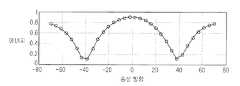
상기 도 4는 MIMO 무선 통신 시스템에서 수신 방향에 따른 수신 신호의 에너지 레벨을 도시한 그래프이다.4 is a graph illustrating energy levels of received signals according to reception directions in a MIMO wireless communication system.
상기 도 4에 도시되어 있는 수신 방향에 따른 수신 신호의 에너지 레벨은 송신기에서 4개의 송신 안테나들을 사용하고, 32개의 빔(
상기 도 4에서는 MIMO 무선 통신 시스템에서 수신 방향에 따른 수신 신호의 에너지 레벨에 대해서 설명하였으며, 다음으로 도 5를 참조하여 도 4의 에너지 레벨들중 최대 에너지 레벨을 가지는 빔에 대해서 설명하기로 한다.In FIG. 4, the energy level of the received signal according to the reception direction in the MIMO wireless communication system has been described. Next, a beam having the maximum energy level among the energy levels of FIG. 4 will be described with reference to FIG. 5.
상기 도 5는 도 4의 에너지 레벨들중 최대 에너지 레벨을 가지는 빔을 도시한 그래프이다.FIG. 5 is a graph illustrating a beam having a maximum energy level among the energy levels of FIG. 4.
상기 도 5에 도시되어 있는 빔은 상기 도 4의 에너지 레벨들중 최대 에너지 레벨을 가지는 빔이며, 상기 도 5에 도시되어 있는 빔은 송신 방향이
상기 도 5에서는 도 4의 에너지 레벨들중 최대 에너지 레벨을 가지는 빔에 대해서 설명하였으며, 다음으로 도 6을 참조하여 도 4의 32개의 빔들중 선택된 빔에 대해서 설명하기로 한다.In FIG. 5, a beam having the maximum energy level among the energy levels of FIG. 4 has been described. Next, a beam selected among the 32 beams of FIG. 4 will be described with reference to FIG. 6.
상기 도 6은 채널의 아이겐 빔과 도 4의 32개 빔들과의 상관값을 도시한 그래프이다. 상기 도 5에서 선택된 두개의 빔의 방향이 도 6에 도시한 그래프의 최대값에 가까운 것을 볼 수 있다. 상기 도 5에 도시되어 있는 빔은 상기 도 4에서 최대 에너지 레벨을 가지는 빔과 동일한 빔이다.FIG. 6 is a graph illustrating a correlation between an eigen beam of a channel and 32 beams of FIG. 4. It can be seen that the directions of the two beams selected in FIG. 5 are close to the maximum values of the graph shown in FIG. 6. The beam shown in FIG. 5 is the same beam as the beam having the maximum energy level in FIG. 4.
상기 도 5에서는 도 4의 32개의 빔들중 선택된 빔에 대해서 설명하였으며, 다음으로 도 7을 참조하여 상기 MIMO 무선 통신 시스템에서 STBC-빔 포밍 방식을 사용할 경우 선택되는 최적 빔 및 준최적 빔에 대해서 설명하기로 한다.In FIG. 5, a selected beam of the 32 beams of FIG. 4 is described. Next, an optimal beam and a suboptimal beam selected when the STBC-beam forming method is used in the MIMO wireless communication system will be described with reference to FIG. 7. Let's do it.
상기 도 7은 MIMO 무선 통신 시스템에서 STBC-빔 포밍 방식을 사용할 경우 선택되는 최적 빔 및 준최적 빔을 도시한 그래프이다.7 is a graph illustrating an optimal beam and a suboptimal beam selected when using the STBC-beam forming method in a MIMO wireless communication system.
상기 도 7에서는 송신기에서 4개의 송신 안테나들을 사용하고, 32개의 빔(


상기 도 7에서는 상기 MIMO 무선 통신 시스템에서 STBC-빔 포밍 방식을 사용할 경우 선택되는 최적 빔 및 준최적 빔에 대해서 설명하였으며, 다음으로 도 8을 참조하여 본 발명에서 제안하는 빔 포밍 방식과 일반적인 빔 포밍 방식들간의 성능을 비교하여 설명하기로 한다.In FIG. 7, an optimal beam and a suboptimal beam selected when the STBC-beam forming method is used in the MIMO wireless communication system have been described. Next, the beam forming method and the general beam forming method proposed by the present invention will be described with reference to FIG. 8. The performance of the methods will be compared and described.
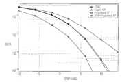
상기 도 8은 본 발명에서 제안하는 빔 포밍 방식과 일반적인 빔 포밍 방식들간의 성능을 비교 도시한 그래프이다.8 is a graph illustrating a comparison between the performance of the beamforming scheme and the conventional beamforming scheme proposed by the present invention.
상기 도 8에 도시되어 있는 성능 그래프들은 안테나 시스템이 0.5λ 이격되어 있는 균일 선형 어레이(ULA: Uniform Linear Array)이고, 채널 환경이 분산 채널 환경인 경우를 가정한 경우의 성능 그래프들이다. 여기서, 상기 분산 채널 환경을 고려하므로 상기 도 8에서는 채널 환경이 LOS가 존재하지 않고 high angular spread 특성을 가지는 저속 플랫 페이딩 채널 환경인 경우를 가정한다. 또한, 상기 도 8에서는 변조 방식으로서 BPSK(Binary Phase Shift Keying) 방식을 사용하고, 송신 안테나들의 개수가 4개이고 수신 안테나의 개수가 1개인 경우를 가정하기로 한다.The performance graphs shown in FIG. 8 are performance graphs assuming that the antenna system is a uniform linear array (ULA) in which 0.5 λ is spaced apart from each other, and the channel environment is a distributed channel environment. Since the distributed channel environment is taken into consideration, it is assumed in FIG. 8 that the channel environment is a low-speed flat fading channel environment in which the LOS does not exist and has a high angular spread characteristic. In FIG. 8, it is assumed that a binary phase shift keying (BPSK) scheme is used as a modulation scheme, and that the number of transmission antennas is four and the number of reception antennas is one.
상기 도 8에는 일반적인 STBC 방식만을 사용하는 경우의 성능 그래프와, 아이겐 빔 포밍(eigen-BF) 방식을 사용하는 경우의 성능 그래프와, 본 발명에서 제안하는 빔 포밍(propose BF) 방식을 사용하는 경우의 성능 그래프와, 상기 STBC 방식과 본 발명에서 제안하는 빔 포밍 방식을 컴바이닝한 방식(STBC + propose BF)을 사용하는 경우의 성능 그래프가 도시되어 있다. 상기 도 8에 도시되어 있는 바와 같이 본 발명에서 제안하는 빔 포밍 방식은 일반적인 STBC 방식에 비해서 더 높은 다이버시티 이득을 획득할 수 있지만, 상기 아이겐 빔 포밍 방식에 비해서는 어레이 이득면에서 손실을 가져온다. 이는 본 발명에서 제안하는 빔 포밍 방식이 빔 설계시 다른 중요 빔들을 무시하고 빔을 설계하기 때문이며, 상기 LOS 채널 모델을 고려할 경우 상기 어레이 이득면에서의 손실을 최소화될 수 있다. 한편, 상기 아이겐 빔 포밍 방식은 어레이 이득면에서 본 발명에서 제안하는 빔 포밍 방식보다 높은 성능을 나타내지만, 연산 복잡도 및 데이터 전송 신뢰성면에서는 본 발명에서 제안하는 빔 포밍 방식이 상기 아이겐 빔 포밍 방식에 대하여 훌륭한 대안임을 알 수 있다.8 illustrates a performance graph when using only a general STBC method, a performance graph when using an eigen-BF method, and a beam forming method proposed by the present invention. The performance graph of Fig. 2 and the performance graph when the STBC method and the beamforming method proposed in the present invention are combined (STBC + propose BF) are shown. As shown in FIG. 8, the beamforming scheme proposed in the present invention can obtain higher diversity gain than the general STBC scheme, but has a loss in array gain compared to the eigen beamforming scheme. This is because the beamforming method proposed in the present invention designes the beam while ignoring other important beams, and the loss in the array gain can be minimized when considering the LOS channel model. On the other hand, the eigen beamforming method exhibits higher performance than the beamforming method proposed by the present invention in terms of array gain. However, in terms of computational complexity and data transmission reliability, the beamforming method proposed by the present invention is more effective than the eigen beamforming method. It's a great alternative.
또한, 상기 도 8에 도시되어 있는 바와 같이 본 발명에서 제안하는 빔 포밍 방식과 STBC 방식과 본 발명에서 제안하는 빔 포밍 방식을 컴바이닝한 방식간의 성능 차는 거의 존재하지 않는다. 이는, 상기 STBC 방식을 사용하기 위해 선택되는 2개의 빔들, 즉 최적 빔과 준최적 빔간의 에너지가 거의 동일하기 때문이다.As shown in FIG. 8, there is almost no difference in performance between the beamforming method proposed by the present invention, the STBC method, and the method of combining the beamforming method proposed by the present invention. This is because the energy between the two beams selected for using the STBC scheme, that is, the optimal beam and the suboptimal beam, is almost the same.
상기 도 8에서는 본 발명에서 제안하는 빔 포밍 방식과 일반적인 빔 포밍 방 식들간의 성능을 비교 설명하였으며, 다음으로 도 9를 참조하여 송신기에서 적용 가능한 빔들 수에 따른, 즉 피드백 비트수에 따른 본 발명에서 제안하는 빔 포밍 방식의 성능을 비교 설명하기로 한다.In FIG. 8, the performance of the beamforming scheme and the conventional beamforming schemes proposed by the present invention are compared and explained. Next, the present invention is described according to the number of beams applicable to the transmitter, that is, the number of feedback bits. The performance of the beamforming scheme proposed in the following will be described in comparison.
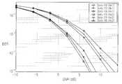
상기 도 9는 송신기에서 적용 가능한 빔들 수에 따른 본 발명에서 제안하는 빔 포밍 방식의 성능을 비교 도시한 그래프이다.9 is a graph illustrating the performance of the beamforming scheme proposed by the present invention according to the number of beams applicable to the transmitter.
상기 도 9에는 송신 안테나들의 개수가 4개이고, 수신 안테나의 개수가 1개인 경우의 빔들 수에 따른 성능 그래프들과, 송신 안테나들의 개수가 4개이고, 수신 안테나들의 개수가 2개인 경우의 빔들 수에 따른 성능 그래프들이 도시되어 있다. 상기 도 9에 도시되어 있는 바와 같이 송신 안테나들의 개수와 송신 안테나들의 개수가 동일하다는 가정하에서는 상기 송신기에서 적용 가능한 빔들의 개수가 많을수록 성능이 향상됨을 알 수 있다.9 shows performance graphs according to the number of beams when the number of transmitting antennas is four and the number of receiving antennas is one, and the number of beams when the number of transmitting antennas is four and the number of receiving antennas is two. Performance graphs are shown. As shown in FIG. 9, it can be seen that the greater the number of beams applicable to the transmitter, the better the performance under the assumption that the number of transmitting antennas and the number of transmitting antennas are the same.
상기 도 9에서는 송신기에서 적용 가능한 빔들 수에 따른 본 발명에서 제안하는 빔 포밍 방식의 성능을 비교 설명하였으며, 다음으로 도 10을 참조하여 본 발명에서 제안하는 빔 포밍 방식과 STBC 방식과 본 발명에서 제안하는 빔 포밍 방식을 컴바이닝한 방식간의 성능을 비교 설명하기로 한다.In FIG. 9, the performance of the beamforming scheme proposed by the present invention is compared according to the number of beams applicable to the transmitter. Next, the beamforming scheme, the STBC scheme, and the proposed scheme are proposed by the present invention with reference to FIG. The performance of the combined method of the beam forming method will be described.
상기 도 10은 본 발명에서 제안하는 빔 포밍 방식과 STBC 방식과 본 발명에서 제안하는 빔 포밍 방식을 컴바이닝한 방식간의 성능을 비교 도시한 그래프이다.10 is a graph illustrating the performance comparison between the beamforming method proposed in the present invention, the STBC method, and the combined method of the beamforming method proposed by the present invention.
상기 도 10에서는 수신기에서의 빔 선정에 심각한 오류가 발생할 경우를 가정할 경우 본 발명에서 제안하는 빔 포밍 방식의 성능을 나타내는 그래프들과 STBC 방식과 본 발명에서 제안하는 빔 포밍 방식을 컴바이닝한 방식간의 성능을 나타내 는 그래프들이 도시되어 있다. 상기 도 10에 도시되어 있는 바와 같이, 수신기에서의 빔 선정에 오류가 발생할 경우에는 본 발명에서 제안하는 빔 포밍 방식만을 사용하는 것보다는 STBC 방식과 본 발명에서 제안하는 빔 포밍 방식을 컴바이닝한 방식을 사용할 경우 그 성능이 향상됨을 알 수 있다. 여기서, 상기 STBC 방식과 본 발명에서 제안하는 빔 포밍 방식을 컴바이닝한 방식을 사용할 경우에는 본 발명에서 제안하는 빔 포밍 방식만을 사용할 경우에 비해서는 피드백 비트수가 증가함은 물론이다.In FIG. 10, assuming that a serious error occurs in beam selection in a receiver, graphs showing the performance of the beamforming scheme proposed by the present invention, a method of combining the STBC scheme and the beamforming scheme proposed by the present invention. Graphs showing liver performance are shown. As shown in FIG. 10, when an error occurs in beam selection in a receiver, a method of combining the STBC method and the beam forming method proposed by the present invention rather than using only the beam forming method proposed by the present invention. It can be seen that the performance is improved when using. In this case, the combination of the STBC method and the beamforming method proposed by the present invention increases the number of feedback bits compared with the case of using only the beamforming method proposed by the present invention.
한편 본 발명의 상세한 설명에서는 구체적인 실시예에 관해 설명하였으나, 본 발명의 범위에서 벗어나지 않는 한도내에서 여러 가지 변형이 가능함은 물론이다. 그러므로 본 발명의 범위는 설명된 실시예에 국한되어 정해져서는 안되며 후술하는 특허청구의 범위뿐만 아니라 이 특허청구의 범위와 균등한 것들에 의해 정해져야 한다.
Meanwhile, in the detailed description of the present invention, specific embodiments have been described, but various modifications are possible without departing from the scope of the present invention. Therefore, the scope of the present invention should not be limited to the described embodiments, but should be defined not only by the scope of the following claims, but also by the equivalents of the claims.
상술한 바와 같은 본 발명은, MIMO/MISO 무선 통신 시스템에서 수신기에서 수신 성능을 최대화할 수 있는 최적 빔에 상응하게 송신기에서 신호를 빔포밍하여 송신함으로써 수신기의 수신 성능을 최대화할 수 있다는 이점을 가진다. 또한, 본 발명은 MIMO 무선 통신 시스템에서 직교 코드를 사용하여 송신 빔들을 구별하도록 하여 비교적 간단한 연산만으로도 최적 빔을 검출할 수 있다는 이점을 가진다. 또한, 본 발명은 상기 빔 포밍 방식과 함께 STBC 방식을 컴바이닝한 방식을 사용함에 있어 상기 최적 빔뿐만 아니라 준최적 빔을 사용함으로써 수신기의 수신 성능을 최대화할 수 있다는 이점을 가진다.As described above, the present invention has the advantage that the reception performance of the receiver can be maximized by beamforming and transmitting a signal at the transmitter corresponding to an optimal beam that can maximize the reception performance at the receiver in a MIMO / MISO wireless communication system. . In addition, the present invention has the advantage that the optimal beam can be detected by a relatively simple operation by using the orthogonal code to distinguish the transmission beams in the MIMO wireless communication system. In addition, the present invention has an advantage in that the reception performance of the receiver can be maximized by using the sub-optimal beam as well as the optimal beam in using the combination of the STBC method together with the beam forming method.
Claims (22)
Translated fromKoreanPriority Applications (2)
| Application Number | Priority Date | Filing Date | Title |
|---|---|---|---|
| KR1020040086383AKR101023366B1 (en) | 2004-10-27 | 2004-10-27 | Apparatus and method for transmitting / receiving signals in a multiple input multiple output wireless communication system using a beamforming method |
| US11/260,852US7711330B2 (en) | 2004-10-27 | 2005-10-27 | Method and apparatus for transmitting/receiving signals in multiple input multiple output wireless communication system employing beam forming scheme |
Applications Claiming Priority (1)
| Application Number | Priority Date | Filing Date | Title |
|---|---|---|---|
| KR1020040086383AKR101023366B1 (en) | 2004-10-27 | 2004-10-27 | Apparatus and method for transmitting / receiving signals in a multiple input multiple output wireless communication system using a beamforming method |
Publications (2)
| Publication Number | Publication Date |
|---|---|
| KR20060037194A KR20060037194A (en) | 2006-05-03 |
| KR101023366B1true KR101023366B1 (en) | 2011-03-18 |
Family
ID=36386251
Family Applications (1)
| Application Number | Title | Priority Date | Filing Date |
|---|---|---|---|
| KR1020040086383AExpired - LifetimeKR101023366B1 (en) | 2004-10-27 | 2004-10-27 | Apparatus and method for transmitting / receiving signals in a multiple input multiple output wireless communication system using a beamforming method |
Country Status (2)
| Country | Link |
|---|---|
| US (1) | US7711330B2 (en) |
| KR (1) | KR101023366B1 (en) |
Cited By (1)
| Publication number | Priority date | Publication date | Assignee | Title |
|---|---|---|---|---|
| KR20200036014A (en)* | 2017-08-11 | 2020-04-06 | 차이나 아카데미 오브 텔레커뮤니케이션즈 테크놀로지 | Method and apparatus for indicating and determining beam information, and communication system |
Families Citing this family (50)
| Publication number | Priority date | Publication date | Assignee | Title |
|---|---|---|---|---|
| US7081597B2 (en)* | 2004-09-03 | 2006-07-25 | The Esab Group, Inc. | Electrode and electrode holder with threaded connection |
| KR101023366B1 (en)* | 2004-10-27 | 2011-03-18 | 삼성전자주식회사 | Apparatus and method for transmitting / receiving signals in a multiple input multiple output wireless communication system using a beamforming method |
| US8724740B2 (en)* | 2005-03-11 | 2014-05-13 | Qualcomm Incorporated | Systems and methods for reducing uplink resources to provide channel performance feedback for adjustment of downlink MIMO channel data rates |
| US8995547B2 (en)* | 2005-03-11 | 2015-03-31 | Qualcomm Incorporated | Systems and methods for reducing uplink resources to provide channel performance feedback for adjustment of downlink MIMO channel data rates |
| US8073068B2 (en) | 2005-08-22 | 2011-12-06 | Qualcomm Incorporated | Selective virtual antenna transmission |
| US20070041457A1 (en) | 2005-08-22 | 2007-02-22 | Tamer Kadous | Method and apparatus for providing antenna diversity in a wireless communication system |
| US7917176B2 (en)* | 2006-02-14 | 2011-03-29 | Nec Laboratories America, Inc. | Structured codebook and successive beamforming for multiple-antenna systems |
| CN101094022B (en)* | 2006-06-19 | 2012-12-19 | 联想(北京)有限公司 | Transmitter, communication system, and communication method |
| US7720470B2 (en)* | 2006-06-19 | 2010-05-18 | Intel Corporation | Reference signals for downlink beamforming validation in wireless multicarrier MIMO channel |
| EP2547003B1 (en)* | 2006-09-06 | 2014-10-15 | Qualcomm Incorporated | Codeword permutation and reduced feedback for grouped antennas |
| US8112038B2 (en)* | 2006-09-15 | 2012-02-07 | Futurewei Technologies, Inc. | Beamforming with imperfect channel state information |
| KR100834631B1 (en)* | 2006-10-25 | 2008-06-02 | 삼성전자주식회사 | Adaptive Transmit Power Allocation Method for Orthogonal Space-Time Block Code Cumbeam Formation in Distributed Wireless Communication Systems |
| KR100842619B1 (en)* | 2006-11-22 | 2008-06-30 | 삼성전자주식회사 | Adaptive Transmission Power Allocation Method for Orthogonal Space-Time Block Code and Beamforming Based on Symbol Error Rate in Distributed Wireless Communication Systems |
| KR20090087907A (en)* | 2006-12-06 | 2009-08-18 | 톰슨 라이센싱 | Reduction of Overhead in Multiple-Input Multiple-Output (MIMO) Systems |
| JP2008211462A (en)* | 2007-02-26 | 2008-09-11 | Fujitsu Ltd | Beam weight detection control method and receiver |
| US7898478B2 (en)* | 2007-02-28 | 2011-03-01 | Samsung Electronics Co., Ltd. | Method and system for analog beamforming in wireless communication systems |
| KR101402290B1 (en)* | 2007-03-26 | 2014-06-02 | 재단법인서울대학교산학협력재단 | Apparatus and method for downlink transmit beamforming considering neighbor cell interference in wireless communication system |
| US8379778B2 (en) | 2007-06-28 | 2013-02-19 | Qualcomm Incorporated | Bursty interference suppression for communications receivers |
| WO2009004768A1 (en)* | 2007-07-05 | 2009-01-08 | Panasonic Corporation | Radio communication device, radio communication system, radio communication method |
| US7714783B2 (en)* | 2007-08-02 | 2010-05-11 | Samsung Electronics Co., Ltd. | Method and system for analog beamforming in wireless communications |
| US7929918B2 (en)* | 2007-08-13 | 2011-04-19 | Samsung Electronics Co., Ltd. | System and method for training the same type of directional antennas that adapts the training sequence length to the number of antennas |
| US7714781B2 (en)* | 2007-09-05 | 2010-05-11 | Samsung Electronics Co., Ltd. | Method and system for analog beamforming in wireless communication systems |
| CN101399637B (en)* | 2007-09-27 | 2012-01-25 | 联想(上海)有限公司 | Method for correcting signal in radio frequency link and pre-corrector |
| KR101386065B1 (en)* | 2007-10-25 | 2014-04-16 | 재단법인서울대학교산학협력재단 | Device for channel information feedback using mmse receiving scheme and method using the same |
| US20090121935A1 (en)* | 2007-11-12 | 2009-05-14 | Samsung Electronics Co., Ltd. | System and method of weighted averaging in the estimation of antenna beamforming coefficients |
| KR101207570B1 (en)* | 2008-01-16 | 2012-12-03 | 삼성전자주식회사 | Method of mitigating inter-cell interference |
| US8051037B2 (en)* | 2008-01-25 | 2011-11-01 | Samsung Electronics Co., Ltd. | System and method for pseudorandom permutation for interleaving in wireless communications |
| US8165595B2 (en)* | 2008-01-25 | 2012-04-24 | Samsung Electronics Co., Ltd. | System and method for multi-stage antenna training of beamforming vectors |
| US8280445B2 (en)* | 2008-02-13 | 2012-10-02 | Samsung Electronics Co., Ltd. | System and method for antenna training of beamforming vectors by selective use of beam level training |
| US8417191B2 (en)* | 2008-03-17 | 2013-04-09 | Samsung Electronics Co., Ltd. | Method and system for beamforming communication in high throughput wireless communication systems |
| KR101507088B1 (en)* | 2008-03-21 | 2015-03-30 | 삼성전자주식회사 | Aparatus and method for uplink baemforming and space-division multiple access in multi-input multi-output wireless communication systems |
| KR101408938B1 (en)* | 2008-04-02 | 2014-06-17 | 보드 오브 리전츠, 더 유니버시티 오브 텍사스 시스템 | Beamforming apparatus and method using generalized eigen analysis in MIMO wireless communication system |
| CN101594176B (en)* | 2008-05-27 | 2012-10-10 | 电信科学技术研究院 | Dual-layer beam forming method and device and equipment supporting dual-layer beam forming transmission |
| US8478204B2 (en)* | 2008-07-14 | 2013-07-02 | Samsung Electronics Co., Ltd. | System and method for antenna training of beamforming vectors having reuse of directional information |
| CN101808357B (en)* | 2009-02-13 | 2012-11-28 | 中兴通讯股份有限公司 | Signal to interference and noise ratio (SINR) estimating method and device |
| US8364193B1 (en)* | 2009-05-04 | 2013-01-29 | Sprint Communications Company L.P. | Forward link power control |
| US9444577B1 (en) | 2010-04-05 | 2016-09-13 | Marvell International Ltd. | Calibration correction for implicit beamformer using an explicit beamforming technique in a wireless MIMO communication system |
| US8971178B1 (en)* | 2010-04-05 | 2015-03-03 | Marvell International Ltd. | Calibration correction for implicit beamformer using an explicit beamforming technique in a wireless MIMO communication system |
| JP5938737B2 (en)* | 2011-06-01 | 2016-06-22 | パナソニックIpマネジメント株式会社 | Radar equipment |
| US9154969B1 (en) | 2011-09-29 | 2015-10-06 | Marvell International Ltd. | Wireless device calibration for implicit transmit |
| US9184806B2 (en) | 2012-03-07 | 2015-11-10 | Lg Electronics Inc. | Method for performing hierarchical beamforming in wireless access system and device therefor |
| CN104335500B (en)* | 2012-05-25 | 2018-11-06 | 三星电子株式会社 | Method and apparatus for transmitting and receiving a reference signal in a mobile communication system using beamforming |
| CN105027461B (en)* | 2013-03-29 | 2019-06-28 | 英特尔Ip公司 | Orthogonal beams for multi-user's multiple-input and multiple-output (MU-MIMO) shape |
| KR102079590B1 (en)* | 2013-05-03 | 2020-02-21 | 삼성전자주식회사 | A method and apparatus for measuring channel information and feedback in a communication system using beamforming |
| US20150341105A1 (en)* | 2014-05-23 | 2015-11-26 | Mediatek Inc. | Methods for efficient beam training and communications apparatus and network control device utilizing the same |
| US10142068B2 (en)* | 2015-05-22 | 2018-11-27 | Futurewei Technologies, Inc. | Methods and device for communications of OFDM signals over wideband carrier |
| CN105743559B (en)* | 2016-04-21 | 2019-01-15 | 西安交通大学 | A kind of Massive MIMO mixed-beam is formed and Space Time Coding multiuser downstream transmission method |
| EP3535859B1 (en) | 2016-11-02 | 2024-04-10 | Telefonaktiebolaget LM Ericsson (PUBL) | Mechanism for switching between uplink and downlink training in hybrid beamforming systems |
| US10509093B2 (en)* | 2016-12-30 | 2019-12-17 | Futurewei Technologies, Inc. | System and method for fast system acquisition and channel estimation |
| KR20220107610A (en) | 2021-01-25 | 2022-08-02 | 삼성전자주식회사 | Method and apparatus of communicaiton in beamformaing based wireless communication system supporting mutiple frequency bands |
Citations (3)
| Publication number | Priority date | Publication date | Assignee | Title |
|---|---|---|---|---|
| US20040002364A1 (en) | 2002-05-27 | 2004-01-01 | Olav Trikkonen | Transmitting and receiving methods |
| KR20040039109A (en)* | 2002-11-01 | 2004-05-10 | 삼성전자주식회사 | Code reuse method and apparatus in CDMA wireless communication system using beam forming by array antenna |
| KR20040041191A (en)* | 2002-11-08 | 2004-05-17 | 한국전자통신연구원 | wireless transmitting and receiving system, and method thereof |
Family Cites Families (15)
| Publication number | Priority date | Publication date | Assignee | Title |
|---|---|---|---|---|
| US7139324B1 (en)* | 2000-06-02 | 2006-11-21 | Nokia Networks Oy | Closed loop feedback system for improved down link performance |
| US6891813B2 (en)* | 2000-12-12 | 2005-05-10 | The Directv Group, Inc. | Dynamic cell CDMA code assignment system and method |
| US6870515B2 (en)* | 2000-12-28 | 2005-03-22 | Nortel Networks Limited | MIMO wireless communication system |
| US6662024B2 (en)* | 2001-05-16 | 2003-12-09 | Qualcomm Incorporated | Method and apparatus for allocating downlink resources in a multiple-input multiple-output (MIMO) communication system |
| RU2316119C2 (en)* | 2002-01-04 | 2008-01-27 | Нокиа Корпорейшн | High speed transmission in mode of transmission and receipt with diversion |
| US6850741B2 (en)* | 2002-04-04 | 2005-02-01 | Agency For Science, Technology And Research | Method for selecting switched orthogonal beams for downlink diversity transmission |
| US8320301B2 (en)* | 2002-10-25 | 2012-11-27 | Qualcomm Incorporated | MIMO WLAN system |
| EP1709752B1 (en)* | 2004-01-20 | 2016-09-14 | LG Electronics, Inc. | Method for transmitting/receiving signals in a mimo system |
| EP1766806B1 (en)* | 2004-06-22 | 2017-11-01 | Apple Inc. | Closed loop mimo systems and methods |
| KR101023366B1 (en)* | 2004-10-27 | 2011-03-18 | 삼성전자주식회사 | Apparatus and method for transmitting / receiving signals in a multiple input multiple output wireless communication system using a beamforming method |
| US8320499B2 (en)* | 2005-03-18 | 2012-11-27 | Qualcomm Incorporated | Dynamic space-time coding for a communication system |
| US8392927B2 (en)* | 2005-05-19 | 2013-03-05 | Hewlett-Packard Development Company, L. P. | System and method for determining a partition of a consumer's resource access demands between a plurality of different classes of service |
| US20070223402A1 (en)* | 2006-03-21 | 2007-09-27 | Shai Waxman | Device, system and method of extended-range wireless communication |
| US7697906B2 (en)* | 2006-03-31 | 2010-04-13 | Intel Corporation | Link performance prediction presence of co-channel interference |
| KR100834631B1 (en)* | 2006-10-25 | 2008-06-02 | 삼성전자주식회사 | Adaptive Transmit Power Allocation Method for Orthogonal Space-Time Block Code Cumbeam Formation in Distributed Wireless Communication Systems |
- 2004
- 2004-10-27KRKR1020040086383Apatent/KR101023366B1/ennot_activeExpired - Lifetime
- 2005
- 2005-10-27USUS11/260,852patent/US7711330B2/enactiveActive
Patent Citations (3)
| Publication number | Priority date | Publication date | Assignee | Title |
|---|---|---|---|---|
| US20040002364A1 (en) | 2002-05-27 | 2004-01-01 | Olav Trikkonen | Transmitting and receiving methods |
| KR20040039109A (en)* | 2002-11-01 | 2004-05-10 | 삼성전자주식회사 | Code reuse method and apparatus in CDMA wireless communication system using beam forming by array antenna |
| KR20040041191A (en)* | 2002-11-08 | 2004-05-17 | 한국전자통신연구원 | wireless transmitting and receiving system, and method thereof |
Cited By (2)
| Publication number | Priority date | Publication date | Assignee | Title |
|---|---|---|---|---|
| KR20200036014A (en)* | 2017-08-11 | 2020-04-06 | 차이나 아카데미 오브 텔레커뮤니케이션즈 테크놀로지 | Method and apparatus for indicating and determining beam information, and communication system |
| KR102305717B1 (en) | 2017-08-11 | 2021-09-27 | 차이나 아카데미 오브 텔레커뮤니케이션즈 테크놀로지 | Method and apparatus for indicating and determining beam information, and communication system |
Also Published As
| Publication number | Publication date |
|---|---|
| US7711330B2 (en) | 2010-05-04 |
| US20060104382A1 (en) | 2006-05-18 |
| KR20060037194A (en) | 2006-05-03 |
Similar Documents
| Publication | Publication Date | Title |
|---|---|---|
| KR101023366B1 (en) | Apparatus and method for transmitting / receiving signals in a multiple input multiple output wireless communication system using a beamforming method | |
| US10630427B2 (en) | Method and apparatus for implementing space frequency block coding in an orthogonal frequency division multiplexing wireless communication system | |
| US10135574B2 (en) | Space-frequency block coding and spatial multiplexing for wireless communications | |
| USRE45203E1 (en) | Apparatus and method for transmitting/receiving data in a mobile communication system using multiple antennas | |
| US7697625B2 (en) | Method and system for transmitting and receiving data streams | |
| US8290539B2 (en) | Beam selection in open loop MU-MIMO | |
| US7764744B2 (en) | Apparatus and method for extending number of antennas in a wireless communication system using multiple antennas | |
| JP5361870B2 (en) | Method and apparatus for preprocessing data transmitted in a multiple input communication system | |
| EP1983781B1 (en) | Wireless communication system using multiantenna transmission technique | |
| US8059771B2 (en) | Method and system for transmitting and receiving data streams | |
| KR100961887B1 (en) | Device and method for channel sounding of a terminal in a wireless communication system | |
| US20050213682A1 (en) | Apparatus and method for transmitting and receiving data in a mobile communication system using an array antenna | |
| KR20070108304A (en) | Method and apparatus for transmitting / receiving channel quality information in multiple transmit / receive antenna system | |
| WO2003023995A1 (en) | A closed-loop signaling method for controlling multiple transmit beams and correspondingy adapted transceiver device | |
| US9008008B2 (en) | Method for communicating in a MIMO context | |
| KR20100053417A (en) | Method of signals transmission and signals reception in the multi-imput multi-output systems | |
| KR20120010235A (en) | Communication method in multi-user MIO network using precoding and precoding device | |
| KR20110127272A (en) | Method and device for communicating in a multi-user network using precoding | |
| KR20070005883A (en) | Transmission Method and Apparatus Using Multiple Antenna Transmission Technology Combining Beamforming, MIMO, and Diversity Techniques | |
| US8942305B2 (en) | Method for communicating in a network | |
| US8477859B2 (en) | System and method for wireless communications with codebook quantization | |
| KR100968118B1 (en) | Device and method for transmitting channel sounding signal in wireless communication system | |
| KR100975730B1 (en) | Random Beamforming Method for Multiple Input and Output Systems | |
| KR20090043174A (en) | Transmission data generation method using precoding, transmission data generation method, generated transmission data reception method, and transmission device | |
| JP4485530B2 (en) | Method and apparatus for wireless communication |
Legal Events
| Date | Code | Title | Description |
|---|---|---|---|
| PA0109 | Patent application | Patent event code:PA01091R01D Comment text:Patent Application Patent event date:20041027 | |
| PG1501 | Laying open of application | ||
| A201 | Request for examination | ||
| PA0201 | Request for examination | Patent event code:PA02012R01D Patent event date:20091026 Comment text:Request for Examination of Application Patent event code:PA02011R01I Patent event date:20041027 Comment text:Patent Application | |
| E701 | Decision to grant or registration of patent right | ||
| PE0701 | Decision of registration | Patent event code:PE07011S01D Comment text:Decision to Grant Registration Patent event date:20110221 | |
| GRNT | Written decision to grant | ||
| PR0701 | Registration of establishment | Comment text:Registration of Establishment Patent event date:20110310 Patent event code:PR07011E01D | |
| PR1002 | Payment of registration fee | Payment date:20110310 End annual number:3 Start annual number:1 | |
| PG1601 | Publication of registration | ||
| FPAY | Annual fee payment | Payment date:20140221 Year of fee payment:4 | |
| PR1001 | Payment of annual fee | Payment date:20140221 Start annual number:4 End annual number:4 | |
| FPAY | Annual fee payment | Payment date:20150212 Year of fee payment:5 | |
| PR1001 | Payment of annual fee | Payment date:20150212 Start annual number:5 End annual number:5 | |
| FPAY | Annual fee payment | Payment date:20160218 Year of fee payment:6 | |
| PR1001 | Payment of annual fee | Payment date:20160218 Start annual number:6 End annual number:6 | |
| FPAY | Annual fee payment | Payment date:20170220 Year of fee payment:7 | |
| PR1001 | Payment of annual fee | Payment date:20170220 Start annual number:7 End annual number:7 | |
| FPAY | Annual fee payment | Payment date:20180220 Year of fee payment:8 | |
| PR1001 | Payment of annual fee | Payment date:20180220 Start annual number:8 End annual number:8 | |
| FPAY | Annual fee payment | Payment date:20190220 Year of fee payment:9 | |
| PR1001 | Payment of annual fee | Payment date:20190220 Start annual number:9 End annual number:9 | |
| FPAY | Annual fee payment | Payment date:20200225 Year of fee payment:10 | |
| PR1001 | Payment of annual fee | Payment date:20200225 Start annual number:10 End annual number:10 | |
| PR1001 | Payment of annual fee | Payment date:20210216 Start annual number:11 End annual number:11 | |
| PR1001 | Payment of annual fee | Payment date:20220221 Start annual number:12 End annual number:12 | |
| PR1001 | Payment of annual fee | Payment date:20230220 Start annual number:13 End annual number:13 | |
| PR1001 | Payment of annual fee | Payment date:20240222 Start annual number:14 End annual number:14 | |
| PC1801 | Expiration of term | Termination date:20250427 Termination category:Expiration of duration |