KR101022763B1 - Meter that stores data, wireless remote meter reading system and control method using same - Google Patents
Meter that stores data, wireless remote meter reading system and control method using sameDownload PDFInfo
- Publication number
- KR101022763B1 KR101022763B1KR1020080086506AKR20080086506AKR101022763B1KR 101022763 B1KR101022763 B1KR 101022763B1KR 1020080086506 AKR1020080086506 AKR 1020080086506AKR 20080086506 AKR20080086506 AKR 20080086506AKR 101022763 B1KR101022763 B1KR 101022763B1
- Authority
- KR
- South Korea
- Prior art keywords
- meter
- data
- metering
- storing
- unique code
- Prior art date
- Legal status (The legal status is an assumption and is not a legal conclusion. Google has not performed a legal analysis and makes no representation as to the accuracy of the status listed.)
- Expired - Fee Related
Links
Images


Classifications
- G—PHYSICS
- G08—SIGNALLING
- G08C—TRANSMISSION SYSTEMS FOR MEASURED VALUES, CONTROL OR SIMILAR SIGNALS
- G08C17/00—Arrangements for transmitting signals characterised by the use of a wireless electrical link
- G—PHYSICS
- G08—SIGNALLING
- G08C—TRANSMISSION SYSTEMS FOR MEASURED VALUES, CONTROL OR SIMILAR SIGNALS
- G08C19/00—Electric signal transmission systems
- G—PHYSICS
- G08—SIGNALLING
- G08C—TRANSMISSION SYSTEMS FOR MEASURED VALUES, CONTROL OR SIMILAR SIGNALS
- G08C25/00—Arrangements for preventing or correcting errors; Monitoring arrangements
- G08C25/04—Arrangements for preventing or correcting errors; Monitoring arrangements by recording transmitted signals
Landscapes
- Physics & Mathematics (AREA)
- General Physics & Mathematics (AREA)
- Engineering & Computer Science (AREA)
- Computer Networks & Wireless Communication (AREA)
- Arrangements For Transmission Of Measured Signals (AREA)
Abstract
Translated fromKoreanDescription
Translated fromKorean본 발명은 무선원격 검침시스템에 관한 것으로, 자세하게는 계량기 내에서 검침데이타를 자체 저장 및 이를 검침기에 송신하는 전자식계량기로부터 근거리 통신을 통하여 원격으로 계량데이타를 수신하므로 가정이나 공장 사무실 등에 있는 가스, 수도, 전기 계량기 등의 사용량을 검침원의 직접방문에 의한 검침 없이 원격 검침을 할 수 있는 무선원격검침시스템 및 그 제어방법에 관한 것이다.The present invention relates to a wireless remote meter reading system, and in detail, since the meter data is remotely received from the electronic meter which stores the metering data in the meter and transmits the metering data to the meter through remote communication, gas, water in a home or factory office, etc. The present invention relates to a wireless remote meter reading system and a control method thereof capable of remote meter reading without a meter reading by a meter visitor.
현재 가스, 전기, 수도와 같은 공공 에너지를 검침하는 방법은 각각의 계량기를 검침원이 직접 방문하여 검침하는 방법이 일반적이다. 구체적인 검침 방법을 설명하자면 검침원의 눈으로 직접 계량기의 변화량 표시부를 보고 그 검침량을 점검표에 적거나 PDA 등의 통신수단에 검침량을 직접 검침 후 기록하여 사용량에 다른 비용을 청구하는 각각의 공급자에게 유무선으로 전송하여 공급자가 사용량을 통합적으로 계산하게 하는 방식이 일반적이다.Currently, the method of reading public energy such as gas, electricity, and water is generally the method of reading each meter in person. To explain the specific metering method, look at the indicator of change of the meter with the eyes of the meter reader, write down the metering amount on the checklist, or record the metering amount directly on the communication means such as PDA, and record it to each supplier who charges a different amount of usage. It is common to transfer by wire or wireless so that the supplier can calculate the usage in an integrated manner.
하지만 이와 같은 종래의 수단은 계량기가 부적정한 장소에 있을 때에는 정 확한 검침이 어렵고 계량기가 있는 가정이나 공장 사무실 등에 사람이 없을 때에는 검침을 할 수가 없다는 단점이 있다.However, such a conventional means has a disadvantage that it is difficult to accurately read when the meter is in an inappropriate place, and can not be read when there is no person in the home or factory office with the meter.
또한 상기 PDA를 이용한 방식도 검침원의 수작업에 의한 검침 없이는 그 정보를 입력할 방법이 없어서 이전 방법의 문제점인 계량기가 부적정한 장소에 있을 때에는 정확한 검침이 어렵고 계량기가 있는 가정이나 공장 사무실 등에 사람이 없을 때에는 검침을 할 수가 없다는 단점이 재현되고 있는 실정이다.In addition, the method using the PDA does not have a method of inputting the information without the manual inspection of the meter reader, so when the meter, which is a problem of the previous method, is in an inappropriate place, it is difficult to accurately read the meter, and there are no people in the home or factory office with the meter. The disadvantage of not being able to read the time is being reproduced.
상기와 같은 종래의 검침방법과 같은 공간적 문제점을 해결하기 위한 해결책으로 유·무선 검침 즉, 원격 검침방법이 기업이나 연구소 등에서 시범사업으로 진행하고 있지만 그 설치비용이 고가라는 문제점과 이를 구현하기 위한 장치 및 방법이 복잡하여 현실적이지 않다는 문제점이 있다.As a solution for solving the spatial problems like the conventional meter reading method as described above, the wired / wireless meter reading, that is, the remote meter reading method is being carried out as a pilot project by companies or research institutes, but the installation cost is expensive and an apparatus for implementing the same. And the method is complex and not realistic.
구체적인 이와 같은 유무선 검침에 대한 종래 기술을 살펴보면 대한민국 공개특허 공개번호 94-25377호가 있는데, 이는 원격검침시스템의 미터기 적산 방법에 관한 것으로, 그 주된 내용은 미터기로부터 발생 된 디지털신호 등의 신호를 분석하여 유효한 정보를 추출하고 이를 적산하는 방법에 관한 것이다. 하지만 이와 같은 종래 특허에서는 구체적인 미터기의 정보를 수집하는 수단이나 정보가 개시되어 있지 않아 원격검침 시스템을 이루기 위한 구체적 방법이 결여되었다는 단점이 있다.Looking at the prior art for the wired and wireless metering in detail, there is a Republic of Korea Patent Publication No. 94-25377, which relates to the meter integration method of the remote meter reading system, the main content is to analyze the signals such as digital signals generated from the meter A method of extracting valid information and integrating it. However, such a conventional patent does not disclose a means or information for collecting specific meter information has a disadvantage in that a specific method for achieving a remote meter reading system is lacking.
또한 대한민국 공개특허 공개번호 92-10524호가 있는데, 이는 무선원격검침시스템과 그 제어방법에 관한 것이다. 그 주된 내용은 검침센터와 검침대상 미터기를 보유한 가입자간의 정보 교환을 무선페이징 및 전선을 복합적으로 사용한다는 것이 주된 내용이다. 하지만 이와 같은 구성에는 필수적으로 페이징 송신수단과 이를 수신하는 수단이 필요하고 또한 기존의 전선망이 연결되도록 하는 수단이 필요하며, 검침뿐 아니라 기타 상황에 따른 정보교환이 가능하도록 하는 수단을 구비해야 하므로 매우 복잡한 시스템으로 구현되어야 한다는 문제점과, 또한 상기와 같이 구체적인 미터기의 정보를 수집하는 수단이나 정보가 개시되어 있지 않아 원격검침 시스템을 이루기 위한 구체적 방법이 결여되었다는 단점이 있다.In addition, there is Republic of Korea Patent Publication No. 92-10524, which relates to a wireless remote meter reading system and its control method. Its main content is the combination of wireless paging and wires for the exchange of information between meter readers and subscribers with bedside meters. However, such a configuration necessitates a paging transmission means and a means for receiving the same, and a means for connecting the existing wire network, and a means for exchanging information according to other situations as well as meter reading. There is a problem in that it must be implemented in a very complex system, and there is also a disadvantage in that a specific method for achieving a telemetering system is lacked because no means or information for collecting specific meter information is disclosed as described above.
또한 대한민국 등록실용신안공보 20-213126호가 있는데, 이는 무선원격검침장치에 관한 것으로, 그 기본적인 구성은 수용가의 가스, 전력, 수도 등의 사용량을 누적시켜 저장하고 있다가 검침원의 요구에 따라 누적된 계량데이타를 즉시 무선으로전송하여 주기 위한 계량기와, 상기 계량기가 설치되어 있는 집과 일정한 거리를 유지하면서 무선주파수 통신으로 계량데이타를 검침할 수 있도록 하는 휴대용 검침단말기와, 상기 휴대용 검침단말기로부터 검침된 데이터를 수집하여 통합 관리할 수 있도록 키 입력장치 및 모니터가 구비되어 검침대상의 수용가의 정보를 제공하는 운용 PC가 연결된 구성을 특징으로 한다.In addition, there is Korea Registered Utility Model Publication No. 20-213126, which relates to a wireless remote meter reading device, the basic configuration of which accumulates and stores the consumption of gas, power, water, etc. of the consumer, and accumulated the measurement according to the meter reading request A meter for transmitting data wirelessly immediately, a portable meter terminal for reading meter data by radio frequency communication while maintaining a constant distance from a house where the meter is installed, and data read from the portable meter terminal A key input device and a monitor are provided to collect and manage the integrated management device.
하지만 상기와 같은 구성을 가진 종래 일반적인 무선주파수 통신방식에 의한 검침은 무선검침을 이루기 위한 구성이 복잡할 뿐만 아니라 계량기의 작동을 유지시키기 위한 전력이 과도하게 소요되는 문제점이 있다. 즉, 상기 무선시스템에서의 가장 큰 단점은 전력을 많이 소모한다는 것과 시스템 제작 비용이 든다는 것이다. 따라서 상기와 같은 시스템이 구현된다 할지라도 시스템을 유지하기 위한 전력비 및 제작비용의 과다로 인해 경제성이 없다는 문제점이 있다.However, the conventional meter reading by the conventional radio frequency communication method having the configuration as described above is a complicated configuration to achieve a radio meter, and there is a problem that excessive power is required to maintain the operation of the meter. In other words, the major disadvantages of the wireless system is that it consumes a lot of power and costs a system. Therefore, even if such a system is implemented, there is a problem in that it is not economical due to excessive power and manufacturing costs for maintaining the system.
또한 상기 특허는 수도, 가스, 전기 검침시 계량기의 성격이 아날로그식, 펄스형, 디지털 형식에 따라 상기 계량기의 구성이 달라지게 되는데 이에 대한 아무 언급도 없어 범용의 구조인지 아닌지가 개시되어 있지 않아 실제 실시하기가 어려운 구성이라는 단점이 있다.In addition, the patent is that the nature of the meter when the meter, water, gas, electricity meter is different depending on the analog, pulse, digital format configuration of the meter, there is no mention of whether it is a general purpose structure or not disclosed There is a disadvantage that the configuration is difficult to implement.
여기서 종래의 계량기를 일예로서 도 1에 도시되었다.Here, a conventional meter is shown in FIG. 1 as an example.
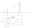
도 1은 종래의 펄스식 계량기를 포함한 검침시스템에서 펄스식 계량기를 도시한 내부측면도이다.1 is an internal side view illustrating a pulsed meter in a meter reading system including a conventional pulsed meter.
도 1을 참조하면, 종래의 펄스식 계량기는 검침기(3)와 전선을 통해 연결되며, 상기 펄스식 계량기는 유량의 흐름에 따라 회전되는 회전마그네트(11)와, 상기 회전마그네트(11)의 회전수를 감지하는 센서(12)와, 상기 센서(12)의 감지신호를 수신하여 검침기(3)에 송신하는 씨피유(2)를 포함한다.Referring to Figure 1, the conventional pulse meter is connected to the
상기 회전마그네트(11)는 N, S극을 갖고 형성되며 물이나 가스등의 계량대상물이 흐르는 통로의 내측에 설치되어 관을 따라서 흐르는 물이나 가스등의 유압에 의해 회전된다.The rotating
상기 센서(12)는 상기 회전마그네트(11)의 회전에 따라서 N극 또는 S극이 정면에 위치되는 순간에 감지신호를 출력한다. 즉 상기 센서(12)는 상기 회전마그네트가 1회전마다 감지신호를 상기 씨피유(2)에 출력한다.The
상기 씨피유(2)는 상기 센서의 출력신호를 수신하고, 이를 인터페이스하여 상기 검침기(3)에 송신한다. 여기서 상기 센서(12)의 출력신호는 펄스식으로서, 상기 씨피유(2)는 상기 센서(12)의 감지신호를 수신하여 근거리 전선통신신호로서 변 환시켜 상기 검침기(3)에 송신한다.The
이와 같은 종래의 검침시스템은 상기 계량기와 검침기간에 전선으로 연결됨에 따라, 연결된 전선이 단선되면 상기 검침기에서 상기 계량기에서 감지된 신호를 수신하지 못하기 때문에 계측신호를 수신하지 못한다. 아울러 상기 계량기는 자체 저장수단이 없이 상기 센서의 감지신호를 수신하면 상기 검침기에 송신하기 때문에 상기 전선이 단선된다 하더라도 이를 감지하여 감지데이타를 저장하거나 또는 단선 이후의 데이타를 송신하지 않기 때문에 전선이 단선 후의 계량데이타가 모두 소실되는 문제점이 있다.As the conventional meter reading system is connected to the meter and the wire during the meter reading period, when the connected wire is disconnected, the meter does not receive the measurement signal because the meter does not receive the signal detected by the meter. In addition, since the meter transmits to the meter when receiving the detection signal of the sensor without its own storage means, even if the wire is disconnected, the meter does not detect and store the sensing data or transmit the data after disconnection, so the wire is disconnected. There is a problem that all of the subsequent weighing data is lost.
본 발명은 상술한 종래의 문제점을 해결하고자 안출된 것으로서, 본 발명의 목적은 계량기 자체에서 계량데이타가 저장됨에 따라 검침기와 계량기간에 통신이 이루어지지 않더라도 측정된 계량데이타가 보존될 수 있는 계량기를 포함하는 계량데이타가 저장되는 계량기를 제공함에 있다.The present invention has been made to solve the above-mentioned conventional problems, an object of the present invention is that the meter is capable of preserving the measured metering data even if communication is not made in the metering period with the metering data is stored in the meter itself It is to provide a meter in which the metering data to be stored.
본 발명의 다른 목적은 각 검침기마다 고유코드를 갖고, 계량데이타를 무선송신하므로 관리자가 직접 검침기를 조작하지 않더라도 일정거리 이내에 접근되면 자동으로 계량 데이타를 원격수신할 수 있는 계량데이타가 저장되는 계량기 및 이를 이용한 무선원격검침시스템 및 그 제어방법을 제공함에 있다.Another object of the present invention has a unique code for each meter, wireless transmission of the weighing data, so that even if the administrator does not operate the meter directly, when the meter is stored within the metering data that can be automatically received remotely weighing data and within a certain distance and The present invention provides a wireless remote meter reading system and a control method thereof.
본 발명은 상기와 같은 목적을 달성하기 위하여 하기와 같은 실시예를 포함한다.The present invention includes the following embodiments in order to achieve the above object.
본 발명의 제1실시예에 따르면, 본 발명의 데이타가 저장되는 계량기에 있어서, 관로를 통하여 이송되는 유량을 감지하는 유량센서와; 상기 유량센서에서 감지된 계량신호를 검침기에 송신하는 제1근거리통신부와; 상기 계량데이타를 저장하는 메모리와; 상기 유량센서에서 감지된 감지신호를 연산하여 계량데이타를 연산하고, 상기 계량데이타를 상기 제1근거리통신부를 통하여 송신 및 상기 메모리에 저장하도록 제어하는 계량제어부를 포함한다.According to a first embodiment of the present invention, a meter in which data of the present invention is stored, comprising: a flow rate sensor for sensing a flow rate transferred through a conduit; A first near field communication unit which transmits the metering signal detected by the flow sensor to the meter; A memory for storing the weighing data; And a weighing control unit configured to calculate weighing data by calculating a sensing signal sensed by the flow sensor, and to control the weighing data to be transmitted and stored in the memory through the first near field communication unit.
본 발명의 제2실시예에 따르면, 제1실시예의 계량데이타가 저장되는 계량기 에 있어서, 상기 계량제어부는 상기 제1근거리통신부의 송수신여부를 확인하고, 상기 제1근거리통신부의 통신장애가 발생됨이 감지되면, 이후에 감지되는 상기 계량데이타를 상기 메모리에 누적저장시키는 것을 특징으로 한다.According to the second embodiment of the present invention, in the meter in which the metering data of the first embodiment is stored, the metering control unit checks whether the first local area communication unit transmits and receives, and detects that a communication failure occurs in the first local area communication unit. If so, it is characterized by accumulating and storing the weighing data detected later in the memory.
본 발명의 제3실시예에 따르면, 제1실시예의 계량데이타가 저장되는 계량기에 있어서, 상기 계량제어부는 상기 유량센서로부터 감지된 계량데이타를 실시간적으로 상기 메모리에 저장하는 것을 특징으로 한다.According to a third embodiment of the present invention, in the meter in which the weighing data of the first embodiment is stored, the weighing control unit stores the weighing data detected from the flow sensor in the memory in real time.
본 발명의 제4실시예에 따르면, 본 발명에 따른 무선원격검침시스템에 있어서, 관로에 흐르는 전기 또는 유류의 양을 감지하고 이를 송신하는 계량기와; 상기 계량기로부터 수신된 계량데이타를 저장하고, 자체 설정된 고유코드를 무선신호로서 발신하는 검침기와; 고유코드 발신지를 스캔하고, 스캔된 검침기로부터 계량데이타를 자동수신하는 휴대용 단말기를 포함한다.According to a fourth embodiment of the present invention, there is provided a wireless remote meter reading system according to the present invention, comprising: a meter for sensing and transmitting an amount of electricity or oil flowing in a pipeline; A meter reader for storing weighing data received from the meter and transmitting a unique code set as a radio signal; And a portable terminal that scans the unique code source and automatically receives metering data from the scanned meter.
본 발명의 제5실시예에 따르면, 제4실시예의 무선원격검침시스템에 있어서, 상기 검침기는 고유코드정보를 저장하는 검침저장부와; 상기 계량기로부터 계량데이타를 수신하는 제2근거리통신부와; 상기 제2근거리통신부로부터 수신된 계량데이타를 저장하는 검침저장부와; 설정된 주기별로 고유코드를 발신하고, 상기 휴대용 단말기로부터 계량데이타요청신호가 수신되면 상기 검침저장부에 저장된 계량데이타를 송신하도록 제어하는 검침제어부와; 상기 검침제어부의 제어신호에 따라서 상기 계량데이타를 원거리 무선신호로 변환시켜 송신하는 검침통신부를 포함한다.According to a fifth embodiment of the present invention, in the wireless remote meter reading system of the fourth embodiment, the meter reading device comprises: a meter reading unit for storing unique code information; A second near field communication unit which receives the metering data from the meter; A meter reading unit for storing metering data received from the second near field communication unit; A meter reading control unit which transmits a unique code for each set period and transmits the metering data stored in the meter reading storage unit when a metering data request signal is received from the portable terminal; And a meter reading communication unit converting the weighing data into a remote radio signal according to a control signal of the meter reading control unit and transmitting the measured data.
본 발명의 제6실시예에 따르면, 제4실시예의 무선원격검침시스템에 있어서, 상기 휴대용 단말기는 상기 스캔부로부터 수신된 고유코드를 확인하고, 상기 고유 코드별로 수신되는 계량데이타를 저장하도록 제어하는 단말기제어부와; 상기 단말기제어부의 제어에 따라서 상기 검침기에서 송신된 계량데이타를 수신하는 데이타송수신부와; 상기 단말기제어부의 제어에 따라서 상기 데이타통신부에서 수신된 계량데이타를 상기 고유코드별로 분류하여 저장하는 데이타저장부를 더 포함한다.According to a sixth embodiment of the present invention, in the wireless remote meter reading system of the fourth embodiment, the portable terminal checks the unique code received from the scanning unit and controls to store the weighing data received for each unique code. A terminal controller; A data transmitter / receiver for receiving weighing data transmitted from the meter under the control of the terminal controller; According to the control of the terminal control unit further comprises a data storage unit for storing the classification data received by the data communication unit by the unique code.
본 발명의 제7실시예에 따르면, 제6실시예의 무선원격검침시스템에 있어서, 상기 휴대용 단말기는 현재 휴대용 단말기의 위치와 검색된 검침기의 위치를 표시하는 네비게이터를 더 포함한다.According to the seventh embodiment of the present invention, in the wireless remote meter reading system of the sixth embodiment, the portable terminal further includes a navigator which displays the position of the current portable terminal and the position of the retrieved meter.
본 발명의 제8실시예에 따르면, 제4실시예의 무선원격검침시스템에 있어서, 상기 무선원격검침시스템은 상기 휴대용 단말기로부터 인터넷 또는 CDMA 통신을 통해 계량데이타를 수신 및 저장하는 중앙서버를 더 포함하고, 상기 휴대용 단말기는 상기 중앙서버에 무선인터넷 또는 CDMA 통신방식으로 송신하는 원거리통신부를 더 포함하는 것을 특징으로 하는 무선원격검침시스템.According to an eighth embodiment of the present invention, in the wireless remote meter reading system of the fourth embodiment, the wireless remote meter reading system further includes a central server for receiving and storing weighing data from the portable terminal through the Internet or CDMA communication. And the portable terminal further comprises a remote communication unit for transmitting to the central server through a wireless internet or a CDMA communication method.
본 발명의 제9실시예에 따르면, 본 발명의 무선원격검침시스템의 제어방법에 있어서, 계량기에서 감지 및 연산된 계량데이타를 저장 및 송신하는 계량기의 감지단계와; 상기 계량기로부터 수신된 계량데이타를 누적 저장하고, 설정된 고유코드에 일치되는 송신요청신호가 수신되면, 계량데이타를 무선송신하는 검침기의 송신단계와; 구획별 영역에서 고유코드 송신신호를 검색하고, 검색된 고유코드에 일치되는 송신요청신호를 송신하여 상기 검침기로부터 계량데이타를 자동수신 및 저장하는 휴대용 단말기의 수신단계를 포함하는 것을 특징으로 하는 한다.According to a ninth embodiment of the present invention, there is provided a control method of a wireless remote meter reading system of the present invention, comprising: a sensing step of storing and transmitting weighing data sensed and calculated by a meter; A metering step of accumulating and storing the metering data received from the meter, and wirelessly transmitting the metering data when a transmission request signal matching the set unique code is received; And a receiving step of the portable terminal for retrieving the unique code transmission signal in each section and transmitting and receiving the transmission request signal corresponding to the retrieved unique code and automatically receiving and storing the weighing data from the meter.
본 발명의 제10실시예에 따르면, 제9실시예의 무선원격검침시스템의 제어방 법에 있어서, 상기 검침기의 송신단계는 설정된 시간주기별로 고유코드를 송신하여, 이후 상기 휴대용 단말기로부터 고유코드에 일치되는 계량데이타요청신호가 수신되면, 저장된 계량데이타를 상기 휴대용 단말기에 송신하는 것을 특징으로 한다.According to a tenth embodiment of the present invention, in the control method of the wireless remote meter reading system of the ninth embodiment, the transmitting step of the meter reading unit transmits a unique code for each set time period, and then matches the unique code from the portable terminal. When the weighing data request signal is received, the stored weighing data may be transmitted to the portable terminal.
본 발명의 제11실시예에 따르면, 제9실시예의 무선원격검침시스템의 제어방법에 있어서, 상기 검침기의 송신단계는 자체 설정된 고유코드에 일치되는 상기 휴대용 단말기의 스캔신호가 수신되면, 상기 고유코드를 포함하는 계량데이타를 송신하는 것을 특징으로 한다.According to an eleventh embodiment of the present invention, in the method for controlling a wireless remote meter reading system according to a ninth embodiment, the transmitting step of the meter is received when the scan signal of the portable terminal matching the unique code is set. Characterized in that for transmitting the weighing data comprising a.
본 발명의 제12실시예에 따르면, 제9실시예의 무선원격검침시스템의 제어방법에 있어서, 상기 계량기의 감지단계는 관로 또는 전선을 통하여 유류, 물 또는 전기의 사용량을 감지하는 감지단계와; 상기 계량데이타를 검침기에 송신하는 송신단계와; 검침기와의 통신유무를 판단하는 통신가능판단단계와; 상기 통신가능판단단계에서 상기 검침기와의 통신이 불가능하면, 감지된 계량데이타를 저장하는 저장단계와; 상기 저장단계이후, 상기 검침기와의 통신가능하면, 상기 저장단계에서 저장된 계량데이타를 상기 검침기에 송신하는 저장데이타송신단계를 포함한다.According to a twelfth embodiment of the present invention, there is provided a control method of a wireless remote meter reading system of a ninth embodiment, wherein the detecting step of the meter comprises: a sensing step of detecting an amount of oil, water or electricity through a pipe or a wire; A transmission step of transmitting the weighing data to a meter reading device; A communication determining step of determining whether or not there is communication with the meter; A storage step of storing the detected weighing data if communication with the meter cannot be made in the communication determining step; After the storing step, if possible to communicate with the meter, the storage data transmission step of transmitting the metering data stored in the storage step to the meter.
본 발명의 제13실시예에 따르면, 제12실시예의 무선원격검침시스템의 제어방법에 있어서, 상기 저장단계는 상기 검침기와 설정된 주기별로 설정된 통신신호가 수신되지 않으면, 통신장애가 발생되었음을 판단하고, 이후부터 감지되는 계량데이타를 누적시켜 저장하는 것을 특징으로 한다.According to a thirteenth embodiment of the present invention, in the control method of the wireless remote meter reading system of the twelfth embodiment, the storing step determines that a communication failure occurs if a communication signal set at the set period with the meter is not received. Accumulate and store the weighing data detected from.
본 발명의 제14실시예에 따르면, 제9실시예의 무선원격검침시스템의 제어방법에 있어서, 상기 휴대용 단말기의 수신단계는 설정된 구획내에서 고유코드를 갖 는 검침기를 검색하는 스캔단계와; 상기 스캔단계에서 검색된 적어도 하나 이상의 검침기에서 선택적으로 계량데이타요청신호를 송신하는 송신하는 계량데이타요청신호송신단계와; 상기 검침기로부터 수신된 계량데이타를 저장하고, 각 검침기별 고유코드로서 분류하여 저장하는 저장단계를 포함한다.According to a fourteenth embodiment of the present invention, in the control method of the wireless remote meter reading system of the ninth embodiment, the receiving step of the portable terminal comprises: a scanning step of searching for a meter having a unique code in a set section; A weighing data request signal transmitting step of selectively transmitting a weighing data request signal from at least one meter read in the scanning step; And a storing step of storing the weighing data received from the meter and classifying and storing the metering data as a unique code for each meter.
본 발명의 제15실시예에 따르면, 제14실시예의 무선원격검침시스템의 제어방법에 있어서, 상기 스캔단계는 상기 검침기로부터 주기적으로 송신되는 고유코드신호를 수신하면, 상기 고유코드를 갖는 검침기에 계량데이타 요청신호를 송신하는 것을 특징으로 한다.According to a fifteenth embodiment of the present invention, in the control method of the wireless remote meter reading system of the fourteenth embodiment, the scanning step is performed by metering to a meter having the unique code when receiving a unique code signal periodically transmitted from the meter. And transmitting a data request signal.
본 발명의 제16실시예에 따르면, 제14실시예의 무선원격검침시스템의 제어방법에 있어서, 상기 스캔단계는 입력된 명령어에 의해 설정된 구획 내에서 각각의 검침기의 고유코드를 요청하는 스캔신호를 출력하는 것을 특징으로 한다.According to a sixteenth embodiment of the present invention, in the control method of the wireless remote meter reading system of the fourteenth embodiment, the scanning step outputs a scan signal for requesting a unique code of each meter in a section set by an input command. Characterized in that.
본 발명의 제17실시예에 따르면, 제14실시예의 무선원격검침시스템의 제어방법에 있어서, 상기 휴대용 단말기의 수신단계는 CDMA 또는 무선인터넷을 통하여 중앙서버에 상기 검침기로부터 수신된 계량데이타를 중앙서버에 송신하는 것을 특징으로 한다.According to a seventeenth embodiment of the present invention, in the control method of the wireless remote meter reading system of the fourteenth embodiment, the receiving step of the portable terminal comprises the central server storing the metering data received from the meter to the central server via CDMA or wireless Internet. It is characterized by transmitting to.
본 발명은 상술한 바와 같이 계량기를 디지털화하여 검침기와의 통신상태를 감지하여 통신장애가 발생되면, 데이타를 자체적으로 누적저장하여 통신재개후 송신함에 따라 계량기와 검침기간의 통신장애로 인한 계량데이타의 소실이 발생되지 않어 더욱 정확한 계량이 가능한 효과가 있다.According to the present invention, when a communication failure occurs by sensing a communication state with a meter by digitizing the meter as described above, data is accumulated and stored by itself and lost after loss of measurement data due to communication failure between the meter and the meter reading period. This does not occur, there is an effect capable of more accurate weighing.
또한 본 발명은 휴대용 단말기를 통하여 무선원격으로 계량데이타를 송수신하므로 검침원이 일일이 검침기를 찾아다녀야 되는 번거로움이 없어서 작업의 용이함과 검침에 따른 시간 및 인력절감이 가능한 효과가 있다.In addition, since the present invention transmits and receives the measurement data wirelessly through the portable terminal, there is no hassle that the meter reader has to visit the meter one by one, thereby reducing the time and manpower according to the ease of operation and meter reading.
이하에서는 본 발명에 따른 계량데이타가 저장가능한 계량기과 이를 이용한 무선원격검침시스템 및 그 제어방법의 바람직한 실시예를 첨부된 도면을 참조하여 상세히 설명한다.Hereinafter, with reference to the accompanying drawings, a preferred embodiment of the meter and the wireless remote meter reading system and control method using the same can store the weighing data according to the present invention will be described in detail.
도 2는 본 발명에 따른 계량데이타가 저장가능한 계량기 및 이를 이용한 무선원격검침시스템의 개념설명을 위한 간략도이다.Figure 2 is a simplified diagram for explaining the concept of a meter and a wireless remote meter reading system using the same can store the weighing data according to the present invention.
도 2를 참조하면, 본 발명에 따른 계량데이타가 저장가능한 계량기(100)를 이용한 무선원격검침시스템은 공급관내의 유량을 감지하여 이를 수치적으로 연산하는 계량기(100)와, 상기 계량기(100)에서 수신된 계량데이타를 표시 및 유 무선통신을 이용하여 송신하는 검침기(200)와, 상기 검침기에서 송신되는 계량데이타를 수신하여 이를 저장하는 휴대용 단말기(300)와, 상기 휴대용 단말기(300)로부터 송신된 데이타를 중계하는 중계기(400)와, 상기 휴대용 단말기(300)로부터 수신되는 계량데이타를 저장 및 이를 근거로 하여 고지서를 발행하는 중앙서버(500)를 포함한다.Referring to Figure 2, the wireless remote meter reading system using a
상기 계량기(100)는 관로내에 흐르는 유량을 감지하여 그 감지된 값을 상기 검침기(200)에 송신한다. 이때 상기 계량기(100)는 상기 검침기(200)와 통신가능여부를 판단하여 통신이 불가능할 경우에는 자체적으로 감지된 계량데이타를 연산하 여 통신재개시까지 계량데이타를 누적시켜 저장한다.The
상기 검침기(200)는 상기 계량기(100)와 유선 또는 무선으로 연결되며, 상기 계량기(100)로부터 수신된 계량데이타를 저장하여 상기 휴대용 단말기(300)로부터 계량데이타 요청신호가 수신되면 상기 휴대용 단말기(300)에 송신한다. 여기서 상기 검침기(200)는 자체 고유코드를 저장하고 있으며 주기적으로 고유코드정보를 송신하여 상기 휴대용 단말기(300)로부터 계량데이타요청신호가 수신되면 계량데이타를 송신한다.The
상기 휴대용 단말기(300)는 상기 검침기(200)와 무선통신을 통하여 원격으로 계량데이타를 수신하여 검침하여 각 검침기별 고유코드로서 분류하여 각각의 계량데이타를 저장한다. 이때 상기 휴대용 단말기(300)는 일정구획내의 검침기(200)에서 송신하는 주기적인 코드발생신호를 검색하거나 또는 무작위로 스캔신호를 송신하여 해당 구역내의 검침기(200)가 상기 스캔신호에 응답하면, 계량데이타를 요청하여 저장한다. 여기서 상기 휴대용 단말기(300)는 PDA, 노트북, 휴대용 피씨와 같이 무선인터넷 또는 CDMA통신이 가능한 구성에 해당된다. 또한 상기 휴대용단말기는 적외선무선통신(IrDA)과, 지그비(Zigbee), RF통신모듈(Radio frequency)와, 불루투스(Bluetooth) 중 적어도 어느 하나를 구비하여 상기 검침기(200)와 통신한다.The
상기 중앙서버(500)는 상기 휴대용 단말기(300)로부터 무선인터넷 또는 CDMA이동통신을 통하여 수신된 각 검침기(200) 별 계량데이타를 수신 및 저장하고, 수신된 계량데이타에 근거하여 사용량에 대한 비용을 청구하는 고지서를 출력한다.The
이와 같은 본 발명의 구성은 계량기(100)와 검침기(200)간의 통신가능여부에 따라서 상기 계량기(100)내에 자체적으로 저장된 데이타를 저장하므로 통신불가능한 시간동안에 계량데이타가 소실되는 경우를 방지할 수 있다.Such a configuration of the present invention stores data stored in the
아울러 상기 검침기(200)와 휴대용 단말기(300)는 무선신호로서 원격 검침이 가능하기 때문에 검침원들이 일일이 가정이나 건물을 방문하여 검침기(200)를 확인하지 않더라도 무선신호로써 상기 검침기(200)에 저장된 계량데이타를 휴대용 단말기(300)로 수신할 수 있어 검침시간 및 인력을 줄일 수 있어 매우 경제적이다.In addition, since the
도 3은 본 발명에 따른 계량데이타가 저장가능한 계량기(100) 및 이를 이용한 무선원격검침시스템에서 계량기(100) 및 검침기(200)를 도시한 블럭도이다.3 is a block diagram illustrating a
도 3을 참조하면, 본 발명에 따른 계량기(100)는 계량데이타를 저장하는 메모리(110)와, 관로내의 유량값을 감지하는 유량센서(120)와, 상기 유량센서(120)에서 감지된 신호를 수치적으로 연산 및 변환하는 계량제어부(130)와, 상기 계량제어부(130)의 제어에 따라서 상기 검침기(200)에 계량데이타를 송신하는 제1근거리통신부(140)를 포함한다.Referring to FIG. 3, the
상기 메모리(110)는 상기 계량제어부(130)로부터 연산된 계량데이타가 송신되며, 송신되는 계량데이타를 누적시켜 저장한다. 아울러 상기 메모리(110)는 상기 계량제어부(130)의 제어에 의해 저장된 계량데이타를 독출하여 상기 계량제어부(130)에 송신한다.The
상기 유량센서(120)는 관로내에서 흐르는 유량을 감지하여 상기 계량제어부(130)에 송신한다. 이때 상기 유량센서(120)는 광센서 또는 압력센서를 적용함이 가능하다.The
상기 제1근거리통신부(140)는 상기 검침기(200)와 주기적으로 송수신하여 상기 계량제어부(130)에 상기 검침기(200)와의 통신가능여부를 확인할 수 있도록 한다. 아울러 상기 제1근거리통신부(140)는 상기 검침기(200)와 유선 또는 무선통신으로서 연결된다.The first short
상기 계량제어부(130)는 상기 유량센서(120)로부터 인가되는 감지신호를 수치적으로 연산하여 계량데이타를 연산하고, 상기 제1근거리통신부(140)를 제어하여 연산된 계량데이타를 상기 검침기(200)에 송신한다. 이때 상기 계량제어부(130)는 상기 제1근거리통신부(140)를 제어하여 상기 검침기(200)와 주기적인 통신을 갖는다. 따라서 상기 계량제어부(130)는 상기 제1근거리통신부(140)를 통하여 상기 검침기(200)로부터 발신된 신호가 설정된 시간간격만큼 인가되지 않으면, 상기 검침기(200)와의 통신 장애가 발생된것을 인지한다. 그러므로 상기 계량제어부(130)는 감지신호를 연산하여 수치적으로 변환된 계량데이타를 상기 메모리(110)에 누적시켜 저장한다. 이후 상기 계량제어부(130)는 상기 제1근거리통신부(140)를 통하여 상기 검침기(200)와의 통신이 재개되면, 상기 메모리(110)에 저장된 계량데이타를 상기 검침기(200)에 일시에 송신하므로 그동안의 사용량에 따른 계량데이타를 정확히 송신하게 된다. 따라서 본 발명은 종래의 문제점으로 지적되었던 상기 계량기(100)에서 검침기(200)로 송신되는 계량데이타가 통신장애로 인하여 통신되지 못하므로 그 시간동안 연산되는 계량데이타가 손실되는 문제점을 해결하였다.The
상기 검침기(200)는 상기 제1근거리통신부(140)와 통신하는 제2근거리통신부(220)와, 상기 휴대용 단말기(300)와 통신하는 검침통신부(230)와, 상기 계량 기(100)로부터 수신된 계량데이타를 누적 저장시키는 검침저장부(210)와, 상기 제2근거리통신부(220)와 검침통신부(230)를 제어하여 수신된 계량데이타를 상기 검침저장부(210)에 저장 및 독출하여 송신하도록 제어하는 검침제어부(240)를 포함한다.The
상기 제2근거리통신부(220)는 상기 제1근거리통신부(140)와 유선 또는 무선으로 연결되어 상기 제1근거리통신부(140)로부터 수신되는 계량데이타를 상기 검침제어부(240)에 인가하고, 상기 검침제어부(240)에서 인가되는 주기적인 송신신호를 상기 제1근거리통신부(140)에 송신한다.The second near
상기 검침저장부(210)는 상기 계량기(100)로부터 수신된 계량데이타를 상기 계량제어부(130)의 제어에 의해 저장 및 독출한다. 이때 상기 검침저장부(210)는 상기 계량데이타의 수치신호를 누적하여 저장한다.The
상기 검침통신부(230)는 RF통신모듈, 불루투스(Bluetooth), 지그비(Zigbee)와 같은 근거리 무선통신방식중 어느 하나로서 상기 휴대용 단말기와 통신을 수행한다. 여기서 상기 검침통신부(230)는 일정구역내에 위치한 휴대용 단말기(300)의 무선신호를 수신 및 상기 검침저장부(210)에 저장된 계량데이타를 송신한다. 여기서 상기 검침통신부(230)는 상기 휴대용 단말기(300)의 스캔신호를 수신하여 상기 검침제어부(240)에 인가하거나 상기 검침제어부(240)의 제어에 의해 일정시간주기별로 고유코드를 송신한다.The
상기 검침제어부(240)는 상기 제2근거리통신부(220)를 통하여 상기 일정시간 주기별로 상기 제1근거리통신부(140)에 통신가능여부를 확인하기 위한 신호를 송신 하도록 제어하고, 아울러 상기 제1근거리통신부(140)로부터 수신된 계량데이타를 상기 검침저장부(210)에 누적되어 저장하도록 제어한다. 또한 상기 검침제어부(240)는 상기 검침통신부(230)로부터 상기 휴대용 단말기(300)의 스캔신호가 수신되면, 자제 저장된 고유코드를 상기 검침통신부(230)를 통하여 송신한다. 여기서 상기 고유코드는 각 검침기(200)별로 서로 다른 코드로서 해당 정보를 통하여 상기 휴대용 단말기(300) 또는 중앙서버에서 주소지 및 등록자를 확인할 수 있다.The meter reading control unit 240 controls to transmit a signal for checking whether communication is possible to the first local
또는 본 발명의 타 실시예로서 상기 검침제어부(240)는 상기의 일실시예와 달리 상기 검침통신부(230)를 제어하여 일정시간주기별로 상기 고유코드를 송신토록 제어한다. 이는 상기 휴대용 단말기(300)에서 상기 고유코드신호를 수신하여 그 정보를 확인하여 상기 검침기(200)에 계량데이타를 요청하게 된다.Alternatively, as another embodiment of the present invention, the meter reading control unit 240 controls the meter
도 4는 본 발명에 따른 계량데이타가 저장가능한 계량기 및 이를 이용한 무선원격검침시스템에서 휴대용 단말기를 도시한 블럭도이다.4 is a block diagram illustrating a portable terminal in a meter capable of storing weighing data and a wireless remote meter reading system using the same according to the present invention.
도 4를 참조하면, 상기 휴대용 단말기(300)는 상기 검침기(200)와 통신하는 데이타송수신부(310)와, 상기 검침기(200)에서 수신된 계량데이타를 저장하는 데이타저장부(320)와, 중앙서버와 통신하는 원거리통신부(330)와, 각 구성을 제어하는 단말기제어부(340)와, 사용자의 조작신호를 출력하는 입력부(350)와, 소정의 화면을 출력하는 디스플레이(360)와, 현재 위치를 추적 및 표시하는 네비게이터(370)와, 위성위치신호를 송수신하는 지피에스안테나(380)를 포함한다.Referring to FIG. 4, the
상기 데이타송수신부(310)는 상기 검침기(200)에서 수신되는 계량데이타 및 고유코드를 수신하여 상기 단말기제어부(340)에 인가하고, 상기 단말기제어부(340) 에 인가하는 스캔신호를 출력한다. 상기 데이타송수신부(310)는 RF통신모듈, 불루투스, 지그비, 적외선데이타통신장치와 같은 근거리무선통신장치 중 어느 하나로서 상기 검침통신부와 통신을 수행한다.The data transmitter /
상기 데이타저장부(320)는 상기 검침기(200)에서 수신된 계량데이타를 각 고유코드별로 분류하여 저장하고, 각 고유코드별 확인정보를 저장한다. 여기서 상기 고유코드별 확인정보는 해당 고유코드의 발신지 주소 및 등록자의 개인정보가 포함된다.The
상기 원거리통신부(330)는 상기 중앙서버와 통신하는 구성으로서, 바람직하게는 CDMA모듈 또는 무선인터넷모뎀 중에서 어느 하나가 선택된다. 상기 원거리통신부(330)는 상기 단말기제어부(340)의 제어에 의해 상기 중앙서버(500)에 측정된 계량데이타와 고유코드확인정보를 송신한다.The
상기 네비게이터(370)는 상기 지피에스안테나(380)를 통한 위성신호에 의해 현재 위치와 상기 검침기(200)에서 포함된 고유코드를 통하여 해당 주소지의 위치를 표시한다. 따라서 상기 휴대용 단말기(300)를 소지한 검침원은 도보로서 상기 디스플레이(360)에서 출력되는 네비게이션 맵을 보면서 현재위치와 검침기(200)의 위치를 육안으로 확인할 수 있다.The
상기 단말기제어부(340)는 상기 데이타송수신부(310)를 제어하여 스캔신호를 송신토록 제어하고, 상기 스캔신호에 따라서 상기 검침기(200)로부터 고유코드신호가 수신되면, 해당 검침기(200)에 계량데이타요청신호를 송신한다. 이후에 상기 단말기제어부(340)는 상기 데이타송수신부(310)를 통하여 수신된 계량데이타를 데이 타저장부(320)에 저장하거나 또는 상기 원거리통신부(330)를 제어하여 상기 중앙서버에 송신한다.The
본 발명은 상기와 같은 구성으로 포함하여 구성되었으며, 이하에서는 본 발명의 작용설명을 하기의 순서도를 이용하여 상세히 설명한다.The present invention was configured to include the configuration as described above, hereinafter will be described in detail using the following flowchart illustrating the operation of the present invention.
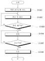
도 5는 본 발명에 따른 계량데이타가 저장가능한 계량기 및 이를 이용한 무선원격검침시스템의 제어방법을 도시한 순서도이다.5 is a flowchart illustrating a control method of a meter and a wireless remote meter reading system using the same according to the present invention.
도 5를 참조하면, 본 발명에 따른 계량기 및 이를 이용한 무선원격검침시스템의 제어방법은 관로내에 흐르는 유량의 감지하는 계량기(100)의 감지단계(S100)와, 상기 계량기(100)에서 수신된 계량데이타를 누적저장하고, 저장된 계량데이타를 휴대용 단말기(300)에 송신하는 검침기(200)의 송신단계(S200)와, 검침기(200)를 검색하여 계량데이타를 수신하고, 이를 중앙서버(500)에 송신하는 휴대용 단말기(300)의 수신단계(S300)를 포함한다.Referring to Figure 5, the meter according to the present invention and a method for controlling the wireless remote meter reading system using the same, the sensing step (S100) of the
상기 계량기(100)의 유량감지단계(S100)는 도 6, 상기 검침기(200)의 데이타송신단계는 도 7, 상기 휴대용 단말기(300)의 수신단계는 도 8을 참조하여 설명한다.The flow rate detecting step S100 of the
도 6은 본 발명에 따른 계량데이타가 저장가능한 계량기 및 이를 이용한 무선원격검침시스템의 제어방법에서 계량데이타가 저장가능한 계량기의 감지단계를 도시한 순서도이다.FIG. 6 is a flowchart illustrating a sensing step of a meter capable of storing meter data in a meter capable of storing meter data and a method of controlling a wireless remote meter reading system using the meter.
도 6을 참조하면, 상기 계량기(100)의 유량감지단계는 관로내에 흐르는 유량감지신호를 수신하는 계량감지신호수신단계(S101)와, 수신된 계량기(100)의 감지신 호를 연산하여 일정수치로 환산되는 계량데이타를 연산하여 상기 검침기(200)에 송신하는 연산 및 송신단계(S102)와, 상기 검침기(200)와의 통신가능여부를 판단하는 송신불가능판단단계(S103)와, 상기 검침기(200)와의 송신이 불가능하면 감지된 계량데이타를 누적시켜 저장하는 저장단계(S104)와, 송신가능여부를 판단하는 송신가능판단단계(S105)와, 송신이 가능하면 누적 저장된 계량데이타를 송신하는 송신단계(S106)를 포함한다.Referring to FIG. 6, the flow rate sensing step of the
상기 계량감지신호 수신단계(S101)는 상기 계량제어부(130)에서 상기 유량센서(120)로부터 감지되는 유량감지신호를 수신하는 단계이다. 여기서 상기 유량센서(120)는 종래의 마그네틱의 회전 횟수에 따른 계량데이타의 연산이 아니라 광센서 또는 압력센서를 통하여 관로내의 유량을 측적하는 것으로서 디지탈신호를 출력한다. 즉, 본 발명은 종래처럼 마그네틱의 회전수를 감지하여 이를 통한 계량데이타를 연산하는 것이 아니라 유량센서(120)를 통한 디지탈신호를 통하여 수치적으로 연산하므로 더욱 정확한 유량의 측정 및 그 측정데이타를 저장함이 가능한다.The weighing detection signal receiving step S101 is a step of receiving a flow rate detection signal detected from the
상기 연산 및 송신단계(S102)는 상기 계량감지부에서 상기 계랑감지신호수신단계에서 수신된 감지신호를 수치적으로 연산하여 상기 검침기(200)에 송신하는 단계이다. 여기서 상기 계량제어부(130)는 상기 유량센서(120)로부터 수신된 감지신호를 수치적으로 연산하여 상기 제1근거리통신부(140)를 제어하여 상기 검침기(200)에 송신한다.The calculating and transmitting step (S102) is a step of numerically calculating the detection signal received in the metering detection signal receiving step in the weighing sensor to transmit to the
여기서 바람직하게로는 상기 메모리(110)에 실시간적으로 누적시켜 저장함이 가능하나, 이때는 상기 메모리(110)의 하드디스크용량이 대용량을 차지해야되거나 또는 일정기간(예를들면, 1년에 한번)에 하드디스크정리를 해야되므로 유지관리의 문제가 발생한다. 따라서 상기 메모리(110)는 소규모 용량으로도 가능하도록 상기 제1근거리통신부(140)와 제2근거리통신부(220)간의 통신이 불가능한 시점에만 상기 계량데이타를 저장하는 것이 바람직하다.Here, preferably, the
상기 송신불가능판단단계(S103)는 상기 계량제어부(130)에서 상기 제1근거리통신부(140)와 제2근거리통신부(220)의 송수신 여부를 판단하여 송신불가능사태가 발생되는 지를 판단하는 단계이다. 상기 계량제어부(130)는 상기 제1근거리통신부(140)로부터 상기 제2근거리통신부(220)에서 일정시간주기별로 송신하는 통신가능코드가 수신되는 지를 확인한다. 이때 상기 계량제어부(130)는 상기 제1근거리통신부(140)로부터 상기 통신가능코드가 수신되지 못한다면, 상기 제1근거리통신부(140) 또는 제2근거리통신부(220)에 이상이 생겨서 통신 불가능함을 판단한다.In the non-transmissible determining step (S103), the weighing
상기 저장단계(S104)는 상기 계량제어부(130)에서 상기 제1근거리통신부(140)와 제2근거리통신부(220)의 통신이 불가능하다고 판단되어 상기 유량센서(120)로부터 수신된 계량데이타를 상기 메모리(110)에 누적시켜 저장하는 단계이다.The storing step (S104) is determined that the communication between the first short-
상기 송신가능판단단계(S105)는 상기 계량제어부(130)에서 상기 제1근거리통신부(140)가 상기 제2근거리통신부(220)에서 송신한 통신가능코드가 인가되는 것을 확인하여 상기 검침기(200)와의 통신이 재개됨을 판단하는 단계이다. 여기서 상기 제1근거리부통신부(140)는 상기 제2근거리통신부(220)로부터 통신가능코드를 수신하여 상기 계량제어부(130)에 인가한다. 따라서 상기 계량제어부(130)는 수신된 통 신가능코드가 설정된 정보(예를들면 상기 검침기(200)의 고유코드정보)를 포함하고 있다면 상기 제1근거리통신부(140)에서 수신한 통신신호가 통신가능코드로 확인하여 통신가능한 것으로 판단한다.The transmittable determination step (S105) confirms that the communication code available from the first short-
상기 송신단계(S106)는 상기 계량제어부(130)에서 상기 저장단계에서 누적저장된 계량데이타를 상기 검침기(200)에 송신하는 단계이다. 이때 상기 메모리(110)에서 저장된 상기 계량데이타는 상기 검침기(200)와의 통신이 불가능한 시점에서부터 누적된 데이타이다. 따라서 상기 계량제어부(130)가 상기 메모리(110)에 저장된 누적계량데이타를 상기 검침기(200)에 송신하면, 상기 검침기(200)에서는 통신불가능 직전의 계량데이타에 누적시켜 저장한다.The transmitting step S106 is a step in which the
도 7은 본 발명에 따른 계량데이타가 저장가능한 계량기 및 이를 이용한 무선원격검침시스템의 제어방법에서 검침기의 송신단계를 도시한 순서도이다.FIG. 7 is a flowchart illustrating a transmission step of a meter in a meter capable of storing weighing data and a method of controlling a wireless remote meter reading system using the meter according to the present invention.
도 7을 참조하면, 상기 검침기(200)의 송신단계(S200)는 상기 계량기(100)로부터 계량데이타를 수신하는 계량데이타수신단계(S201)와, 상기 계량데이타수신단계(S201)에서 수신된 계량데이타를 누적저장시키는 저장단계(S202)와, 일정시간을 주기로 하여 고유코드를 송신하는 고유코드송신단계(S203)와, 상기 휴대용 단말기(300)로부터 스캔신호가 수신되기까지 대기하는 대기단계(S204)와, 상기 고유코드송신단계(S203) 이후 또는 상기 대기단계(S204)에서 상기 휴대용 단말기(300)의 스캔신호가 수신되는 지를 판단하는 스캔신호 수신판단단계(S205)와, 상기 스캔신호 수신판단단계(S205)에서 상기 휴대용 단말기(300)의 스캔신호가 수신되면 저장된 계량데이타를 송신하는 송신단계(S206)를 포함한다.Referring to FIG. 7, the transmitting step S200 of the
상기 계량데이타수신단계(S201)는 상기 검침제어부(240)에서 상기 제2근거리통신부(220)를 통하여 상기 계량기(100)에서 송신하는 계량데이타를 수신하는 단계이다. 여기서 상기 검침제어부(240)는 상기 제2근거리통신부(220)에서 수신된 계량데이타를 일정 수치로 연산한다. 아울러 상기 검침제어부(240)는 상기 제2근거리통신부(220)를 제어하여 일정시간주기별로 통신가능코드를 송신하도록 하며, 이는 상술한 바와 같은 계량기(100)와 검침기(200)간의 통신가능여부를 판단하도록 한다.The metering data receiving step (S201) is a step of receiving metering data transmitted from the
상기 저장단계(S202)는 상기 검침제어부(240)에서 상기 계량데이타수신단계(S201)에서 수신된 계량데이타를 이전저장된 계량데이타에 누적시켜서 상기 검침저장부(210)에 저장시킨다.The storing step (S202) accumulates the weighing data received in the metering data receiving step (S201) in the metering control unit 240 in the metering data stored previously stored in the
상기 고유코드송신단계(S203)와 대기단계(S204)는 본 발명에 따른 검침기(200)의 일실시예와 타실시예로 구분하여 설명한다. 본 발명은 휴대용 단말기(300)의 원격검침을 위하여 상기 휴대용 단말기(300)에서 먼저 송신하면 이를 수신한 검침기(200)에서 상기 계량데이타를 송신함도 가능하며 이는 대기단계에서 설명한다. 또한 본 발명은 상기 검침기(200)에서 먼저 일정시간주기별로 고유코드를 송신하면, 이를 수신한 휴대용 단말기(300)에서 계량데이타요청신호를 수신하는 실시예를 모두 포함한다. 이하에서는 상기 두 가지 실시예를 상기 고유코드송신단계(S203)와 대기단계(S204)로 각각 분류하여 설명한다.The unique code transmission step (S203) and the waiting step (S204) will be described by dividing into one embodiment and another embodiment of the
상기 고유코드송신단계(S203)는 상기 검침제어부(240)에서 상기 검침통신부(230)를 제어하여 검침기(200) 자체에 부여된 고유코드를 일정시간주기별로 송신토록 제어한다. 이는 상기 검침통신부(230)의 통신영역 내에 있는 휴대용 단말 기(300)에서 수신할 수 있다. 따라서 상기 휴대용 단말기(300)를 갖고 이동중인 검침원이 상기 검침통신부(230)의 통신가능 영역 내에 위치되면 상기 검침기(200)에서 송신되는 고유코드정보를 수신하여 해당 검침기(200)에 계량데이타를 요청하는 계량데이타요청신호를 송신하는 단계이다.In the unique code transmission step (S203), the meter reading control unit 240 controls the meter
상기 대기 단계(S204)는 상기 검침제어부(240)에서 상기 검침통신부(230)를 상기 휴대용 단말기(300)의 스캔신호를 수신하기 이전까지 대기하는 단계이다.The waiting step (S204) is a step in which the meter reading control unit 240 waits until the
상기 스캔신호수신단계(S205)는 상술한 바와 같이 상기 고유코드송신(S203) 및 대기단계(S204) 이후에 상기 검침제어부(240)에서 상기 검침통신부(230)를 통하여 상기 휴대용 단말기(300)의 스캔신호가 수신되는 지를 판단하는 단계이다.The scan signal receiving step S205 is performed by the meter reading control unit 240 through the
상기 송신단계(S206)는 상기 검침제어부(240)에서 상기 휴대용 단말기(300)로부터 스캔신호가 인가되면, 상기 스캔신호에 포함된 자체 고유코드에 일치되는 확인정보가 포함되었는지를 확인 후 상기 검침저장부(210)에 저장된 계량데이타를 송신하는 단계이다. 여기서 상기 검침제어부(240)는 상기 고유코드 송신단계(S203) 이후, 또는 대기 중에서 상기 고유코드에 일치되는 코드확인정보가 포함된 스캔신호 또는 계량데이타요청신호가 수신되면, 상기 검침저장부(210)에 저장된 계량데이타를 상기 휴대용 단말기(300)에 송신한다.In the transmitting step (S206), when the scan signal is applied from the
도 8은 본 발명에 따른 계량데이타가 저장가능한 계량기 및 이를 이용한 무선원격검침시스템의 제어방법에서 휴대용 단말기의 수신단계를 도시한 순서도이다.8 is a flowchart illustrating a receiving step of a portable terminal in a meter capable of storing weighing data and a method of controlling a wireless remote meter reading system using the meter according to the present invention.
도 8을 참조하면, 상기 휴대용 단말기(300)의 수신단계(S300)는 상기 설정된 구역내의 검침기(200)를 스캔하는 스캔단계(S301)와, 상기 스캔단계(S301)에서 검 색된 검침기(200)로부터 계량데이타를 수신 및 저장하는 수신단계(S302)와, 저장된 계량데이타를 중앙서버에 송신하는 서버송신단계(S303)를 포함한다.Referring to FIG. 8, the reception step S300 of the
상기 스캔단계(S301)는 상기 단말기제어부(340)가 상기 입력부(350)에서 인가되는 사용자의 명령신호에 따라서 설정된 구역내에 스캔신호를 출력하는 단계이다. 여기서 상기 단말기제어부(340)는 상기 데이타송수신부(310)를 제어하여 스캔신호를 송신한다.The scanning step (S301) is a step in which the
이때 상기 휴대용 단말기(300)는 앞서 설명한 바와 같이 상기 검침기(200)가 일정시간주기별로 고유코드를 송신하도록 설정되면(S203), 무작위 스캔신호의 출력이 아니라 상기 검침기(200)로부터의 고유코드를 수신한 이후에 해당 검침기(200)에 스캔신호 또는 계량데이타요청신호를 송신한다.In this case, when the
또는 상기 검침기(200)가 상기와 같은 대기단계(S204)를 유지하도록 설정되었다면, 상기 휴대용 단말기(300)는 스캔신호를 송신하여, 상기 스캔신호를 수신한 검침기(200)로부터 고유코드가 수신되면 상기 검침기(200)에 계량데이타요청신호를 송신한다.Alternatively, if the
또한 상기 단말기제어부(340)는 상기 검침기(200)로부터 고유코드가 수신되면, 상기 고유코드로서 분류되는 주소지와 등록자의 개인정보를 상기 디스플레이(360)에 출력한다. 아울러 상기 단말기제어부(340)는 상기 네비게이터(370)를 제어하여 현재위치와 상기 검침기(200)의 위치를 출력하여 표시한다.In addition, when a unique code is received from the
즉 본 발명은 검침원이 상기 휴대용 단말기(300)를 소지하고 설정된 구획영역내에 존재한다면, 상기 휴대용 단말기(300)가 먼저 스캔신호를 송신하여 검색된 검침기(200)에 계량데이타를 요청하거나 또는 상기 검침기(200)에서 주기별로 자동송신되는 고유코드를 수신하여 설정된 구획내에 존재하는 휴대용 단말기(300)가 이를 수신하여 계량데이타 요청신호를 해당 검침기(200)에 송신한다.That is, in the present invention, if the meter reader has the
상기 수신단계(S302)는 상기 단말기제어부(340)에서 상기 데이타송수신부(310)를 제어하여 상기 검침기(200)로부터 계량데이타를 수신 및 저장하는 단계이다. 상기 단말기제어부(340)는 상기 데이타송수신부(310)를 통하여 수신된 검침기(200)의 계량데이타를 상기 데이타저장부(320)에 저장한다. 이때 상기 데이타저장부(320)에 저장되는 계량데이타는 상기 고유코드로서 분류되어 저장된다.In the receiving step S302, the
상기 서버송신단계(S303)는 상기 단말기제어부(340)에서 상기 입력부(350)에서 인가되는 명령신호에 의해 상기 휴대용단말기에 저장된 계량데이타를 상기 중앙서버(500)에 송신하는 단계이다. 여기서 상기 단말기 제어부(340)는 상기 입력부(350)에 의해 선택된 고유코드로 분류되는 계량데이타를 송신하거나 일괄적으로 상기 검침기(200)로 부터 수신과 동시에 상기 중앙서버에 송신함이 가능하다. 여기서 상기 단말기제어부(340)는 상기 원거리통신부(330)를 통하여 중계소(400)를 거쳐서 상기 중앙서버(500)에 송신되도록 CDMA 또는 무선인터넷신호를 송신한다. 그러므로 상기 중앙서버(500)는 각각의 고유코드별로 분류되는 계량데이타를 수신하여 해당 검침기(200)의 등록자에게 사용요금에 대한 청구서를 발행할 수 있다.The server transmitting step (S303) is a step in which the
또는 본 발명은 상술한 바와 같이 휴대용 단말기(300)에서 중앙서버에 송신하지 않고, 자체 저장된 상태로 갖고 있다가 유선인터넷을 통하여 상기 중앙서버에 송신함도 가능하다. 바람직하게로는 상기 휴대용 단말기(300)는 유무선인터넷이 모 두 가능한 휴대용 피씨(PC) 또는 노트북, PDA중에 어느 하나가 바람직하다.Alternatively, as described above, the
이상에서 설명한 본 발명은 전술한 실시예 및 도면에 한정되는 것이 아니고, 본 발명의 기술적 사상을 벗어나지 않는 범위 내에서 여러 가지 변형 및 변경이 가능이 본 고안이 속하는 기술분야에서 통상의 지식을 가진 자에게 있어 명백할 것이다.The present invention described above is not limited to the above-described embodiments and drawings, and various modifications and changes can be made without departing from the technical spirit of the present invention. It will be obvious to you.
도 1은 종래의 계량기를 도시한 설명도,1 is an explanatory diagram showing a conventional meter;
도 2는 본 발명에 따른 계량데이타가 저장가능한 계량기 및 이를 이용한 무선원격검침시스템의 개념설명을 위한 간략도,Figure 2 is a simplified view for explaining the concept of a meter and a wireless remote meter reading system using the same to store the weighing data according to the present invention,
도 3은 본 발명에 따른 계량데이타가 저장가능한 계량기 및 이를 이용한 무선원격검침시스템에서 계량기 및 검침기를 도시한 블럭도,3 is a block diagram illustrating a meter and a meter in a meter capable of storing weighing data and a wireless remote meter reading system using the meter according to the present invention;
도 4는 본 발명에 따른 계량데이타가 저장가능한 계량기 및 이를 이용한 무선원격검침시스템에서 휴대용 단말기를 도시한 블럭도,4 is a block diagram showing a portable terminal in a meter capable of storing weighing data and a wireless remote meter reading system using the same according to the present invention;
도 5는 본 발명에 따른 계량데이타가 저장가능한 계량기 및 이를 이용한 무선원격검침시스템의 제어방법을 도시한 순서도,5 is a flow chart showing a control method of a meter and a wireless remote meter reading system using the same to store the weighing data according to the present invention,
도 6은 본 발명에 따른 계량데이타가 저장가능한 계량기 및 이를 이용한 무선원격검침시스템의 제어방법에서 계량데이타가 저장가능한 계량기의 감지단계를 도시한 순서도,FIG. 6 is a flowchart illustrating a sensing step of a meter capable of storing weighing data and a meter capable of storing weighing data in a control method of a wireless remote meter reading system using the meter according to the present invention;
도 7은 본 발명에 따른 계량데이타가 저장가능한 계량기 및 이를 이용한 무선원격검침시스템의 제어방법에서 검침기의 송신단계를 도시한 순서도,7 is a flowchart illustrating a transmission step of a meter in a meter capable of storing weighing data and a method of controlling a wireless remote meter reading system using the same according to the present invention;
도 8은 본 발명에 따른 계량데이타가 저장가능한 계량기 및 이를 이용한 무선원격검침시스템의 제어방법에서 휴대용 단말기의 수신단계를 도시한 순서도이다.8 is a flowchart illustrating a receiving step of a portable terminal in a meter capable of storing weighing data and a method of controlling a wireless remote meter reading system using the meter according to the present invention.
*도면의 주요부분을 표시한 부호의 설명** Description of Symbols Marking Major Parts of Drawings *
100 : 계량기 110 : 메모리100: meter 110: memory
120 : 유량센서 130 : 계량제어부120: flow sensor 130: weighing control unit
140 : 제1근거리통신부 200 : 검침기140: first short-range communication unit 200: meter reading
210 : 검침저장부 220 : 제2근거리통신부210: meter reading unit 220: second short-range communication unit
230 : 검침통신부 240 : 검침제어부230: meter reading communication unit 240: meter reading control unit
250 : 검침안테나 300 : 휴대용 단말기250: meter reading antenna 300: portable terminal
310 : 데이타송수신부 320 : 데이타저장부310: data transmission and reception unit 320: data storage unit
330 : 원거리통신부 340 : 단말기제어부330: telecommunication unit 340: terminal control unit
350 : 입력부 360 : 디스플레이350: input unit 360: display
370 : 네비게이터 380 : 지피에스안테나370: Navigator 380: GPS antenna
Claims (17)
Translated fromKoreanPriority Applications (1)
| Application Number | Priority Date | Filing Date | Title |
|---|---|---|---|
| KR1020080086506AKR101022763B1 (en) | 2008-09-02 | 2008-09-02 | Meter that stores data, wireless remote meter reading system and control method using same |
Applications Claiming Priority (1)
| Application Number | Priority Date | Filing Date | Title |
|---|---|---|---|
| KR1020080086506AKR101022763B1 (en) | 2008-09-02 | 2008-09-02 | Meter that stores data, wireless remote meter reading system and control method using same |
Publications (2)
| Publication Number | Publication Date |
|---|---|
| KR20100027557A KR20100027557A (en) | 2010-03-11 |
| KR101022763B1true KR101022763B1 (en) | 2011-03-17 |
Family
ID=42178504
Family Applications (1)
| Application Number | Title | Priority Date | Filing Date |
|---|---|---|---|
| KR1020080086506AExpired - Fee RelatedKR101022763B1 (en) | 2008-09-02 | 2008-09-02 | Meter that stores data, wireless remote meter reading system and control method using same |
Country Status (1)
| Country | Link |
|---|---|
| KR (1) | KR101022763B1 (en) |
Cited By (1)
| Publication number | Priority date | Publication date | Assignee | Title |
|---|---|---|---|---|
| KR20230004164A (en)* | 2021-06-30 | 2023-01-06 | 부경엔지니어링주식회사 | Water Electric Gas Integrated Telecalibration System |
Families Citing this family (7)
| Publication number | Priority date | Publication date | Assignee | Title |
|---|---|---|---|---|
| KR100989712B1 (en)* | 2010-08-05 | 2010-10-26 | 주식회사 하이텍이피씨 | Recovering method after communication failure in automatic meter reading terminal |
| KR101321004B1 (en)* | 2013-03-19 | 2013-10-23 | 신민철 | Manhole with display unit of digital water meter |
| KR101616257B1 (en)* | 2014-03-17 | 2016-04-28 | 송창석 | A Device for Checking Water Meter without Power and a System for Checking Water Meter Having the Same |
| KR102198252B1 (en)* | 2019-02-19 | 2021-01-04 | 유명규 | Read meter, reading method thereof, and computer program performing the method |
| KR102269254B1 (en)* | 2019-02-19 | 2021-06-29 | 유명규 | Read meter |
| KR102450079B1 (en)* | 2022-03-15 | 2022-09-30 | 최석준 | LoRaman-based remote meter reading system |
| KR102765476B1 (en)* | 2022-05-25 | 2025-02-07 | 곽영민 | Gas and chemical pipe identification device |
Citations (4)
| Publication number | Priority date | Publication date | Assignee | Title |
|---|---|---|---|---|
| KR20010025432A (en)* | 2000-12-27 | 2001-04-06 | 전주범 | An integrated-measurement method using remote measuring instrument |
| JP2004020278A (en) | 2002-06-13 | 2004-01-22 | Kawamura Electric Inc | Power monitor system |
| KR100434656B1 (en)* | 2001-11-28 | 2004-06-07 | (주)누리텔레콤 | Integrated Automatic Meter Reading System using Wire/Wireless Multiple Communication |
| KR100612069B1 (en)* | 2005-11-14 | 2006-08-11 | (주) 테크윈 | Wireless remote meter reading system using Zigbee RF module and its reading method |
- 2008
- 2008-09-02KRKR1020080086506Apatent/KR101022763B1/ennot_activeExpired - Fee Related
Patent Citations (4)
| Publication number | Priority date | Publication date | Assignee | Title |
|---|---|---|---|---|
| KR20010025432A (en)* | 2000-12-27 | 2001-04-06 | 전주범 | An integrated-measurement method using remote measuring instrument |
| KR100434656B1 (en)* | 2001-11-28 | 2004-06-07 | (주)누리텔레콤 | Integrated Automatic Meter Reading System using Wire/Wireless Multiple Communication |
| JP2004020278A (en) | 2002-06-13 | 2004-01-22 | Kawamura Electric Inc | Power monitor system |
| KR100612069B1 (en)* | 2005-11-14 | 2006-08-11 | (주) 테크윈 | Wireless remote meter reading system using Zigbee RF module and its reading method |
Cited By (2)
| Publication number | Priority date | Publication date | Assignee | Title |
|---|---|---|---|---|
| KR20230004164A (en)* | 2021-06-30 | 2023-01-06 | 부경엔지니어링주식회사 | Water Electric Gas Integrated Telecalibration System |
| KR102499618B1 (en)* | 2021-06-30 | 2023-02-14 | 부경엔지니어링주식회사 | Water Electric Gas Integrated Telecalibration System |
Also Published As
| Publication number | Publication date |
|---|---|
| KR20100027557A (en) | 2010-03-11 |
Similar Documents
| Publication | Publication Date | Title |
|---|---|---|
| KR101022763B1 (en) | Meter that stores data, wireless remote meter reading system and control method using same | |
| KR101037433B1 (en) | Wireless communication system for underground facility management | |
| US9338411B2 (en) | System and method for remote utility meter reading | |
| CA2624033C (en) | Method and system for collecting meter readings in wireless transmissions from unlisted customers | |
| EP0948781B1 (en) | System for measuring domestic consumption of electricity, heat, water and gas | |
| US8878690B2 (en) | AMR transmitter and method using multiple radio messages | |
| JP2008516234A (en) | Tracking vibrations in pipeline networks. | |
| KR101768679B1 (en) | Wireless remote meter reading system capable of real-time monitoring | |
| KR20080112692A (en) | Remote meter reading system | |
| US7605717B2 (en) | AMR transmitter with programmable operating mode parameters | |
| KR20190026305A (en) | Home automation automatic meter reading wall-pad and home automation automatic meter reading and advabced metering infrastructure system including the same | |
| Farah et al. | Smart water technology for leakage detection: feedback of large-scale experimentation | |
| JP5476602B2 (en) | Portable information terminal used in gas meter remote management system | |
| JP2001222785A (en) | Radio meter inspection system | |
| KR101003918B1 (en) | Automatic remote meter reading system using pulse output meter and RF, CDMA communication | |
| KR101972650B1 (en) | remote water leakage detecting system and method of remote detecting water leakage | |
| KR100681490B1 (en) | Remote metering system for LPI storage tank | |
| CN202931564U (en) | Mobile internet technology based terminal of Internet of Things | |
| KR101192745B1 (en) | Wireless remote meter reading system | |
| KR20050012572A (en) | Method and System for Reducing Power Consumption of Wireless Modem for Use in Telemetering System | |
| KR20030030594A (en) | A System for position recognition of underground facilities | |
| WO2018128538A1 (en) | Fluid meter with supplementary wireless communication module | |
| KR20140119139A (en) | Sensor device | |
| KR100363838B1 (en) | apartment control system utilizing internet | |
| Fabian-Manuel et al. | Sniffer. Testing the radio function of water and heat meters |
Legal Events
| Date | Code | Title | Description |
|---|---|---|---|
| A201 | Request for examination | ||
| PA0109 | Patent application | St.27 status event code:A-0-1-A10-A12-nap-PA0109 | |
| PA0201 | Request for examination | St.27 status event code:A-1-2-D10-D11-exm-PA0201 | |
| PG1501 | Laying open of application | St.27 status event code:A-1-1-Q10-Q12-nap-PG1501 | |
| D13-X000 | Search requested | St.27 status event code:A-1-2-D10-D13-srh-X000 | |
| D14-X000 | Search report completed | St.27 status event code:A-1-2-D10-D14-srh-X000 | |
| E902 | Notification of reason for refusal | ||
| PE0902 | Notice of grounds for rejection | St.27 status event code:A-1-2-D10-D21-exm-PE0902 | |
| R17-X000 | Change to representative recorded | St.27 status event code:A-3-3-R10-R17-oth-X000 | |
| T11-X000 | Administrative time limit extension requested | St.27 status event code:U-3-3-T10-T11-oth-X000 | |
| E13-X000 | Pre-grant limitation requested | St.27 status event code:A-2-3-E10-E13-lim-X000 | |
| P11-X000 | Amendment of application requested | St.27 status event code:A-2-2-P10-P11-nap-X000 | |
| P13-X000 | Application amended | St.27 status event code:A-2-2-P10-P13-nap-X000 | |
| E701 | Decision to grant or registration of patent right | ||
| PE0701 | Decision of registration | St.27 status event code:A-1-2-D10-D22-exm-PE0701 | |
| GRNT | Written decision to grant | ||
| PR0701 | Registration of establishment | St.27 status event code:A-2-4-F10-F11-exm-PR0701 | |
| PR1002 | Payment of registration fee | St.27 status event code:A-2-2-U10-U11-oth-PR1002 Fee payment year number:1 | |
| PG1601 | Publication of registration | St.27 status event code:A-4-4-Q10-Q13-nap-PG1601 | |
| PN2301 | Change of applicant | St.27 status event code:A-5-5-R10-R13-asn-PN2301 St.27 status event code:A-5-5-R10-R11-asn-PN2301 | |
| FPAY | Annual fee payment | Payment date:20140219 Year of fee payment:4 | |
| PR1001 | Payment of annual fee | St.27 status event code:A-4-4-U10-U11-oth-PR1001 Fee payment year number:4 | |
| LAPS | Lapse due to unpaid annual fee | ||
| PC1903 | Unpaid annual fee | St.27 status event code:A-4-4-U10-U13-oth-PC1903 Not in force date:20150310 Payment event data comment text:Termination Category : DEFAULT_OF_REGISTRATION_FEE | |
| PC1903 | Unpaid annual fee | St.27 status event code:N-4-6-H10-H13-oth-PC1903 Ip right cessation event data comment text:Termination Category : DEFAULT_OF_REGISTRATION_FEE Not in force date:20150310 | |
| P22-X000 | Classification modified | St.27 status event code:A-4-4-P10-P22-nap-X000 | |
| P22-X000 | Classification modified | St.27 status event code:A-4-4-P10-P22-nap-X000 |