KR101020247B1 - Screwdriver for pedicle screw - Google Patents
Screwdriver for pedicle screwDownload PDFInfo
- Publication number
- KR101020247B1 KR101020247B1KR1020100106006AKR20100106006AKR101020247B1KR 101020247 B1KR101020247 B1KR 101020247B1KR 1020100106006 AKR1020100106006 AKR 1020100106006AKR 20100106006 AKR20100106006 AKR 20100106006AKR 101020247 B1KR101020247 B1KR 101020247B1
- Authority
- KR
- South Korea
- Prior art keywords
- housing
- rod
- pedicle screw
- pedicle
- screw
- Prior art date
- Legal status (The legal status is an assumption and is not a legal conclusion. Google has not performed a legal analysis and makes no representation as to the accuracy of the status listed.)
- Expired - Fee Related
Links
Images


Classifications
- A—HUMAN NECESSITIES
- A61—MEDICAL OR VETERINARY SCIENCE; HYGIENE
- A61B—DIAGNOSIS; SURGERY; IDENTIFICATION
- A61B17/00—Surgical instruments, devices or methods
- A61B17/56—Surgical instruments or methods for treatment of bones or joints; Devices specially adapted therefor
- A61B17/58—Surgical instruments or methods for treatment of bones or joints; Devices specially adapted therefor for osteosynthesis, e.g. bone plates, screws or setting implements
- A61B17/68—Internal fixation devices, including fasteners and spinal fixators, even if a part thereof projects from the skin
- A61B17/70—Spinal positioners or stabilisers, e.g. stabilisers comprising fluid filler in an implant
- A61B17/7074—Tools specially adapted for spinal fixation operations other than for bone removal or filler handling
- A61B17/7076—Tools specially adapted for spinal fixation operations other than for bone removal or filler handling for driving, positioning or assembling spinal clamps or bone anchors specially adapted for spinal fixation
- A61B17/7082—Tools specially adapted for spinal fixation operations other than for bone removal or filler handling for driving, positioning or assembling spinal clamps or bone anchors specially adapted for spinal fixation for driving, i.e. rotating, screws or screw parts specially adapted for spinal fixation, e.g. for driving polyaxial or tulip-headed screws
- A—HUMAN NECESSITIES
- A61—MEDICAL OR VETERINARY SCIENCE; HYGIENE
- A61B—DIAGNOSIS; SURGERY; IDENTIFICATION
- A61B17/00—Surgical instruments, devices or methods
- A61B17/56—Surgical instruments or methods for treatment of bones or joints; Devices specially adapted therefor
- A61B17/58—Surgical instruments or methods for treatment of bones or joints; Devices specially adapted therefor for osteosynthesis, e.g. bone plates, screws or setting implements
- A61B17/68—Internal fixation devices, including fasteners and spinal fixators, even if a part thereof projects from the skin
- A61B17/70—Spinal positioners or stabilisers, e.g. stabilisers comprising fluid filler in an implant
- A61B17/7001—Screws or hooks combined with longitudinal elements which do not contact vertebrae
- A61B17/7035—Screws or hooks, wherein a rod-clamping part and a bone-anchoring part can pivot relative to each other
Landscapes
- Health & Medical Sciences (AREA)
- Neurology (AREA)
- Orthopedic Medicine & Surgery (AREA)
- Life Sciences & Earth Sciences (AREA)
- Surgery (AREA)
- Heart & Thoracic Surgery (AREA)
- Engineering & Computer Science (AREA)
- Biomedical Technology (AREA)
- Nuclear Medicine, Radiotherapy & Molecular Imaging (AREA)
- Medical Informatics (AREA)
- Molecular Biology (AREA)
- Animal Behavior & Ethology (AREA)
- General Health & Medical Sciences (AREA)
- Public Health (AREA)
- Veterinary Medicine (AREA)
- Surgical Instruments (AREA)
Abstract
Translated fromKoreanDescription
Translated fromKorean본 발명은 척추를 교정하도록 설치되는 척추경 나사못을 척추경에 체결하는 척추경 나사못 체결용 드라이버에 관한 것이다.The present invention relates to a screwdriver for pedicle screw fastening to the pedicle screw pedicle screw installed to correct the spine.
척추는 신체를 지지하는 부분으로서, 통상 24개의 뼈로 구성되며 뼈와 인접한 뼈의 사이에는 디스크가 구비되고, 뼈의 중앙으로는 신경이 지나가도록 구성된다.The spine is a part that supports the body, and usually consists of 24 bones, with a disk between the bones and the adjacent bones, and a nerve passing through the center of the bones.
이러한 척추는 신체를 지탱할 뿐만 아니라, 모든 내장을 보호하며 신체가 움직일 수 있는 근원이 되는 부분으로 중요한 기능을 한다.These vertebrae not only support the body, but also protect all the internal organs and play an important role as the source from which the body can move.
그러나, 척추가 인위적으로 손상되거나 퇴행성 또는 잘못된 자세로 인해 척추가 손상되거나 틀어질 경우 척추를 지나가는 신경을 압박함으로써, 심한 통증을 유발하게 된다.However, if the spine is damaged or twisted due to artificial injury, degenerative or incorrect posture, the nerve passing through the spine is compressed, causing severe pain.
통증이 경미한 경우에는 물리치료를 통한 치료방법을 사용하고 있지만 통증이 심한 경우에는 척추경을 고정하는 고정장치를 삽입하여 척추의 위치를 바로잡거나 신경을 압박하는 부분을 압박하지 않도록 교정을 해야 한다.If the pain is mild, physical therapy is used. However, if the pain is severe, the fixation device to fix the pedicle should be inserted to correct the position of the spine or to compress the pressure so as not to press the nerve.
일반적으로 척추 교정 시술은 복수의 척추경에 척추경 나사못을 체결하고, 척추경과 인접한 척추경을 가로지르는 로드를 결합하여 척추의 교정을 수행한다.In general, the chiropractic procedure is to perform vertebrae correction by fastening pedicle screws to a plurality of pedicles, and combining rods across the pedicle and adjacent pedicles.
척추 교정 시술은 신경을 압박하는 척추경과 인접한 척추경의 사이를 로드에 의해 벌어지도록 척추를 교정함으로써, 척추경이 신경을 압박하는 것을 방지할 수 있다.The chiropractic procedure can prevent the pedicle from compressing the nerve by correcting the spine so as to be opened by the rod between the pedicle that compresses the nerve and the adjacent pedicle.
한편, 척추 교정 시술에 사용되는 척추경 나사못은 컵형상으로 형성되고 로드가 안착될 수 있도록 상부가 개방된 안착홈이 형성된 헤드와, 상기 헤드의 하부로 회동 가능하게 결합되며 척추경에 나사체결될 수 있도록 나사산이 형성된 몸체로 구성된다.On the other hand, the pedicle screw used in the chiropractic procedure is formed in a cup shape and the head is formed with a seating groove with an open upper portion so that the rod can be seated, rotatably coupled to the lower portion of the head and screwed to the pedicle It is made up of a threaded body.
그리고, 헤드의 상부 내주 면에는 안착홈에 안착된 로드가 헤드에 고정될 수 있도록 멈춤나사가 결합되는 나사산이 형성되고, 몸체의 상단에는 체결공구가 안착되는 안착홈이 형성된다.Then, the upper inner circumferential surface of the head is formed with a screw thread to which the stop screw is coupled so that the rod seated in the seating groove is fixed to the head, and a seating groove for seating the fastening tool is formed at the top of the body.
이러한 구성을 가지는 척추경 나사못은 드라이버라고 일컫는 체결공구를 사용하여 척추경에 체결되는데, 이 드라이버는 일반적인 스크류 드라이버와 원리는 유사하지만 상기와 같은 척추경 나사못을 체결하기 위해 일반적인 스크류 드라이버와는 다른 구성을 가진다.Pedicle screws having such a configuration are fastened to the pedicle using a fastening tool called a screwdriver, which is similar in principle to a conventional screw driver but is different from a conventional screw driver to fasten the pedicle screw as described above. Has
종래의 척추경 나사못 체결용 드라이버는 일단에는 손잡이가 구비되고 타단에는 헤드를 고정하여 회전시키는 팁이 구비된 메인로드와, 메인로드의 외면을 감싸는 로드 하우징으로 구성된다.Conventional pedicle screw fastening screwdriver is provided with a main rod having a handle at one end and a tip for rotating and fixing the head at the other end, and a rod housing surrounding the outer surface of the main rod.
그리고, 로드 하우징의 끝단에는 척추경 나사못의 헤드부와 나사체결되는 나사산이 형성된다.And, the end of the rod housing is formed with a thread screwed to the head of the pedicle screw.
이렇게 구성된 종래의 척추경 나사못 체결용 드라이버는 메인로드의 팁을 몸체에 형성된 안착홈에 안착시키고, 척추경 나사못의 몸체에서 헤드가 회동되지 않도록 로드 하우징의 끝단에 형성된 나사산을 헤드에 형성된 나사산에 나사체결하는 형태로 척추경 나사못을 결합한다.The conventional pedicle screw fastening driver configured as described above seats the tip of the main rod in the seating groove formed in the body, and screw the thread formed at the end of the rod housing to the thread formed in the head so that the head is not rotated in the body of the pedicle screw. Join the pedicle screw in the form of fastening.
이 후, 척추경 나사못이 결합된 드라이버를 회전시키면서 척추경에 척추경에 척추경 나사못을 체결한다.Afterwards, the pedicle screw is fastened to the pedicle while the screwdriver is coupled to the pedicle screw.
하지만, 종래의 척추경 나사못 체결용 드라이버는 척추경 나사못을 척추에 체결 시 척추경 나사못과 로드 하우징이 나사체결되는 반대방향으로 드라이버를 회전시킬 경우 나사체결이 용이하게 풀린다.However, in the conventional pedicle screw fastening driver, when the pedicle screw is fastened to the spine, the screwing is easily loosened when the screwdriver is rotated in the opposite direction in which the pedicle screw and the rod housing are screwed.
이와 같이, 나사체결이 풀리면 드라이버의 회전 시 팁이 안착홈에서 쉽게 이탈되어 팁의 마모 또는 팁의 파손 등이 발생하고, 이로 인해 드라이버를 교체해야 하는 문제점이 있었다.As such, when the screw is loosened, the tip is easily detached from the seating groove during rotation of the driver, causing wear of the tip or breakage of the tip, which causes a problem in that the driver needs to be replaced.
본 발명은 전술한 바와 같은 문제점을 해결하기 위한 것으로서, 본 발명이 해결하고자 하는 과제는 척추경 나사못을 척추에 시술 시 척추경 나사못이 드라이버에서 이탈되어 팁의 마모 또는 파손되는 것을 방지할 수 있는 척추경 나사못 체결용 드라이버를 제공하는 것이다.The present invention is to solve the problems as described above, the problem to be solved by the present invention is a spine that can prevent the wear or breakage of the tip of the pedicle screw is detached from the driver when the pedicle screw on the spine It is to provide a screwdriver for tightening a light screw.
상기한 과제를 해결하기 위한 본 발명의 실시예에 따른 척추경 나사못 체결용 드라이버는 나사산이 형성된 몸체와 상기 몸체를 지지하는 헤드부로 구성되는 척추경 나사못을 척추경에 체결하는 척추경 나사못 체결용 드라이버에 있어서, 상기 몸체를 지지하는 팁부가 일단에 형성되고, 손잡이가 타단에 결합되는 메인로드, 상기 메인로드가 중앙에 삽입되어 상기 메인로드를 중심으로 회전 가능하게 설치되며, 상기 헤드부와 나사체결되는 나사부가 형성된 로드 하우징, 및 상기 메인로드에 구비되어 상기 로드 하우징이 상기 헤드부와 나사체결되는 반대방향으로의 회전을 제한 및 해제하는 잠금부를 포함한다.Driver for fastening the pedicle screw according to an embodiment of the present invention for solving the above problems is a screwdriver for pedicle screw fastening to the pedicle pedicle screw consisting of a screw thread formed body and the head portion for supporting the body to the pedicle In the end, the tip portion for supporting the body is formed at one end, the main rod handle is coupled to the other end, the main rod is inserted into the center rotatably installed around the main rod, screwed with the head portion A rod housing having a screw portion formed therein, and a lock portion provided on the main rod to limit and release rotation in an opposite direction in which the rod housing is screwed with the head portion.
상기 잠금부는 상기 로드 하우징의 둘레에 톱니 형상으로 형성되는 래칫 기어, 상기 메인로드에 회전가능하게 지지되어 상기 래칫 기어를 감싸는 래칫 다이얼,및 상기 래칫 다이얼의 회전에 따라 상기 래칫 기어에 걸쳐지거나 걸쳐지는 것이 해제되는 스토퍼를 포함할 수 있다.The locking portion is a ratchet gear formed in the shape of a saw tooth around the rod housing, a ratchet dial rotatably supported on the main rod to enclose the ratchet gear, and the ratchet gear is over or spanned according to the rotation of the ratchet dial. It may include a stopper to be released.
상기 메인로드에는 틸트볼이 설치되고, 상기 래칫 다이얼에는 상기 틸트볼이 안착되는 볼 안착홈이 형성되어 상기 래칫 다이얼의 회전각도를 제한할 수 있다.A tilt ball is installed on the main rod, and a ball seating groove in which the tilt ball is seated is formed in the ratchet dial to limit the rotation angle of the ratchet dial.
상기 로드 하우징은 길이가 신축 가능하도록 상기 헤드부와 나사체결되는 나사부가 끝단에 형성된 제1 하우징과, 상기 제1 하우징이 슬라이딩 이동가능하도록 내부에 삽입되는 제2 하우징을 포함할 수 있다.The rod housing may include a first housing having a threaded portion screwed to the head portion so that the length thereof is stretchable and a second housing inserted therein to allow the first housing to slide.
상기 로드 하우징의 외부에서 슬라이딩 이동가능하도록 상기 로드 하우징이 내부에 삽입되며, 시술자가 파지하는 핸들 커버를 더 포함할 수 있다.The rod housing may be inserted into the rod housing so as to be slidably movable from the outside of the rod housing, and may further include a handle cover held by an operator.
상기 핸들 커버에는 상기 로드 하우징이 상기 메인로드의 하단 방향으로 탄성력이 발생하도록 상기 로드 하우징을 탄성적으로 지지하는 탄성부재가 더 구비될 수 있다.The handle cover may further include an elastic member for elastically supporting the rod housing such that the rod housing generates an elastic force in a lower direction of the main rod.
상기 핸들커버의 하부에는 상기 핸들커버의 내부로 슬라이딩 이동가능하며, 상기 로드 하우징의 하단에 걸쳐져 상기 탄성부재를 지지하는 스프링 푸셔가 구비될 수 있다.A lower portion of the handle cover may be slidably moved into the handle cover and may be provided with a spring pusher that covers the lower end of the rod housing to support the elastic member.
본 발명에 따르면, 잠금부가 척추경 나사못의 헤드부와 로드 하우징이 나사체결되는 방향의 반대방향으로 로드 하우징이 회전하는 방지할 수 있어 척추경 나사못을 척추에 시술 시 드라이버와 척추경 나사못의 나사체결이 풀려 팁부의 마모 또는 팁부가 파손되는 것을 방지할 수 있는 효과가 있다.According to the present invention, the locking portion can prevent the rod housing from rotating in a direction opposite to the direction in which the head portion and the rod housing of the pedicle screw is screwed, screwing the screwdriver and the pedicle screw when performing the pedicle screw on the spine This loosening has the effect of preventing the tip portion from being worn or breaking the tip portion.
또한, 로드 하우징의 나사부가 탄성부재에 의해 나사체결되는 방향으로 탄성적으로 지지되기 때문에 드라이버와 척추경 나사못을 용이하게 체결할 수 있다.In addition, since the screw portion of the rod housing is elastically supported in the direction of screwing by the elastic member, it is possible to easily fasten the driver and the pedicle screw.
또한, 그립부가 구비되어 시술자가 척추경 나사못을 척추에 용이하게 체결할 수 있다.In addition, the grip is provided so that the operator can easily fasten the pedicle screw to the spine.
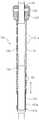
도 1은 본 발명의 실시예에 따른 척추경 나사못 체결용 드라이버를 도시한 측면도이다.
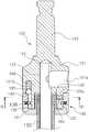
도 2는 본 발명의 실시예에 따른 척추경 나사못 체결용 드라이버를 도시한 측단면도이다.
도 3은 본 발명의 실시예에 따른 척추경 나사못 체결용 드라이버의 메인로드의 측단면도이다.
도 4는 도 3의 A-A선을 따라 절개한 단면도이다.
도 5는 본 발명의 실시예에 따른 척추경 나사못 체결용 드라이버의 로드 하우징을 도시한 측면도이다.
도 6은 본 발명의 실시예에 따른 척추경 나사못 체결용 드라이버의 그립부를 도시한 단면도이다.
도 7는 본 발명의 실시예에 따른 척추경 나사못 체결용 드라이버의 래칫 다이얼을 도시한 사시도이다.
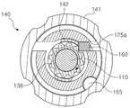
도 8은 본 발명의 실시예에 따른 척추경 나사못 체결용 드라이버의 잠금부를 도시한 단면도이다.
도 9은 도 7에 B-B선을 따라 절개한 단면도로서, 본 발명의 실시예에 따른 척추경 나사못 체결용 드라이버의 잠금부를 나타낸 단면도이다.
도 10은 본 발명의 실시예에 따른 척추경 나사못 체결용 드라이버의 래칫 다이얼이 잠금 위치에 위치된 상태를 나타낸 단면도이다.1 is a side view showing a screwdriver for pedicle screw fastening according to an embodiment of the present invention.
Figure 2 is a side cross-sectional view showing a screwdriver for pedicle screw fastening according to an embodiment of the present invention.
Figure 3 is a side cross-sectional view of the main rod of the screwdriver for pedicle screw fastening according to an embodiment of the present invention.
4 is a cross-sectional view taken along line AA of FIG. 3.
Figure 5 is a side view showing a rod housing of the screwdriver for pedicle screw fastening according to an embodiment of the present invention.
Figure 6 is a cross-sectional view showing the grip of the screwdriver for pedicle screw fastening according to an embodiment of the present invention.
Figure 7 is a perspective view of the ratchet dial of the screwdriver for pedicle screw fastening according to an embodiment of the present invention.
8 is a cross-sectional view showing a locking portion of the screwdriver for pedicle screw fastening according to an embodiment of the present invention.
9 is a cross-sectional view taken along the line BB in FIG.
10 is a cross-sectional view showing a state in which the ratchet dial of the pedicle screw fastening driver according to the embodiment of the present invention is located in the locked position.
이하, 첨부된 도면을 참조하여 본 발명의 실시예를 상세히 설명하도록 한다.Hereinafter, embodiments of the present invention will be described in detail with reference to the accompanying drawings.
도 1에 도시된 바와 같이, 본 발명의 실시예에 따른 척추경 나사못 체결용 드라이버(100)는 척추를 교정하도록 척추경에 척추경 나사못(200)을 체결하는 드라이버에 관한 것이다.As shown in Figure 1, the pedicle
여기서, 척추경 나사못(200)은 헤드부(210)와 손잡이(300)로 구성되며, 손잡이(300)는 하부로 갈수록 좁아지는 막대 형상으로 외면에는 척추경 나사못(200)이 척추경에 고정될 수 있도록 나사산이 형성될 수 있다.Here, the
또한, 손잡이(300)의 상단부분에는 척추경 나사못 체결용 드라이버(100)가 결합될 수 있도록 육각, 십자, 일자, 또는 별 모양 등의 다각 형상의 팁 안착홈(231)이 형성될 수 있다.In addition, the upper portion of the
그리고, 헤드부(210)는 상부가 개방된 컵형상으로 하단 중앙에는 손잡이(300)의 상단이 회동 가능하도록 결합되고, 헤드부(210)의 측면에는 상부로 개방된 안착홈(211)이 형성될 수 있다. 이때, 컵 형상의 헤드부(210)의 내주 면에는 외면에 나사산이 형성된 멈춤나사가 체결될 수 있는 나사산(213)이 형성될 수 있다.In addition, the
이러한 척추경 나사못(200)은 각각의 척추경에 척추경 나사못(200)을 설치한 후 막대형상의 로드를 어느 하나의 척추경 나사못(200)의 안착홈(211)과 인접한 척추경 나사못(200)의 안착홈(211)을 가로지르도록 안착시키고, 각각의 헤드부(210)의 상부로 멈춤나사(미도시)를 체결하여 로드(미도시)를 고정시킴으로써, 복수의 척추경의 사이 간격을 조절하는 형태로 척추를 교정시킬 수 있다.The
도 2 및 도 3에 도시된 바와 같이, 본 발명의 실시예에 따른 척추경 나사못 체결용 드라이버(100)는 메인로드(110)를 포함할 수 있다. 이 메인로드(110)는 막대형상으로 형성되고, 일단에는 척추경 나사못(200)이 결합되도록 팁부(111)가 형성되며, 타단에는 손잡이(300)가 결합될 수 있다.As shown in Figure 2 and 3, the pedicle
한편, 팁부(111)는 척추경 나사못(200)의 손잡이(300)에 형성되는 팁 안착홈(231)과 대응되는 형상으로 형성되어 팁부(111)가 팁 안착홈(231)에 끼워질 수 있다.On the other hand, the
그리고, 메인로드(110)는 손잡이(300)가 착탈 가능하게 결합될 수 있도록 손잡이 아답터(120)를 포함할 수 있다.And, the
이 손잡이 아답터(120)는 메인로드(110)의 팁부(111)가 설치되는 메인로드(110)의 반대방향 끝단에 결합되며, 손잡이 아답터(120)는 메인로드(110)의 둘레보다 큰 둘레를 가지는 본체(121)와, 본체(121)의 상부로 돌출되어 손잡이(300)가 착탈가능하게 결합되는 착탈부(123)와, 그리고 본체(121)의 착탈부(123)가 형성되는 반대방향으로는 즉, 본체(121)의 하부로 돌출되는 다이얼 안착부(125)를 포함할 수 있다.The
여기서, 착탈부(123)는 착탈부(123)에 착탈 가능하게 결합되는 손잡이(300)의 구성에 따라 다양하게 형성될 수 있으므로 그 형상을 한정하지 않으며, 착탈 가능한 손잡이(300)는 공지의 기술로 다양하게 개시되어 있으므로 그 상세한 설명은 생략한다.Here, the
다만, 본 발명의 실시예에서의 손잡이(300)는 손으로 파지하기가 용이한 "T"자 형상으로 형성된 손잡이(300)를 적용하여 도면에 도시하였다(도 1 참조).However, the
그리고, 다이얼 안착부(125)의 하단 중앙에는 하기에 설명될 로드 하우징(130)의 끝단이 일부 삽입되는 하우징 삽입홈(126)이 형성되고, 하우징 삽입홈(126)의 하단 중앙에는 본체(121)까지 메인로드(110)가 삽입되어 고정될 수 있는 로드 삽입홈(122)이 형성될 수 있다.In addition, a
이때, 로드 삽입홈(122)으로 삽입된 메인로드(110)는 본체(121)의 측면에 형성된 관통공(121a)을 통해 나사체결되는 멈춤나사에 의해 손잡이 아답터(120)에 고정될 수 있다.In this case, the
도 4의 도시된 바와 같이, 손잡이 아답터(120)의 다이얼 안착부(125)에는 커버 안착부의 중앙에서 일측으로 편심되어 다이얼 안착부(125)의 측면을 관통하는 스토퍼 삽입홈(125a)이 형성될 수 있다. 이 스토퍼(160) 홈은 하기에 설명될 스토퍼(160)가 슬라이딩 이동 가능하도록 설치되며, 하우징 삽입홈(126)과 연통된다.As shown in FIG. 4, the
또한, 본체(121)의 하단 더 구체적으로는 다이얼 안착부(125)의 상단 둘레의 본체(121)에는 틸트볼(165)이 설치될 수 있는 볼 삽입홈(121b)이 형성되고, 이 볼 삽입홈(121b)에는 구형상의 틸트볼(165)이 본체(121)의 하단으로 일부 돌출되도록 탄성부재(166)에 의해 볼 삽입홈(121b)에서 탄성적으로 지지될 수 있다. 여기서, 탄성부재(166)는 코일 스프링인 것이 바람직하다.In addition, the lower end of the
더불어, 손잡이 아답터(120)는 메인로드(110)와 일체로 형성될 수 있음은 물론이다.In addition, the
도 5에 도시된 바와 같이, 본 발명의 실시예에 따른 척추경 나사못 체결용 드라이버(100)는 로드 하우징(130)을 포함할 수 있다.As shown in FIG. 5, the pedicle
이 로드 하우징(130)은 메인로드(110)가 삽입되어 회전할 수 있도록 메인로드(110)를 감싸는 형태의 관형상으로 형성될 수 있으며, 로드 하우징(130)의 끝단 더 구체적으로는 메인로드(110)의 팁부(111)가 위치되는 끝단에는 헤드부(210)의 내주면에 형성된 나사산과 나사체결되는 나사부(132)가 형성될 수 있다.The
한편, 로드 하우징(130)은 길이 조절이 가능하도록 제1 하우징(135)과 제2 하우징(131)을 포함할 수 있다.Meanwhile, the
제1 하우징(135)은 관 형상으로 형성되어 메인로드(110)의 상단 부분 더 구체적으로는 메인로드(110)의 상단에 결합된 손잡이 아답터(120)의 하우징 삽입홈(126)에 끝단이 일부 삽입된다.The
그리고, 제1 하우징(135)의 내부에는 제2 하우징(131)의 상단 부분이 걸쳐질 수 있는 하우징 걸림턱(131b)이 형성될 수 있으며, 하우징 삽입홈(126)으로 삽입된 제1 하우징(135)의 반대방향 끝단으로는 제1 하우징(135)의 서로 대향되는 양 측면을 각각 관통하여 설치되는 결합핀(139)이 삽입될 수 있는 핀 삽입공(137)이 형성될 수 있다.In addition, a
또한, 제1 하우징(135) 상부의 측면에는 슬라이딩 키홈(136)이 형성될 수 있다.In addition, a sliding
제2 하우징(131)은 메인로드(110)가 관통되도록 관 형상으로 형성되고, 제1 하우징(135)의 하단 내부로 제2 하우징(131)의 상단의 일부가 삽입되도록 위치된다.The
한편, 제2 하우징(131) 상부의 서로 마주보는 양측 면에는 제1 하우징(135)과 제2 하우징(131)을 서로 연결하도록 제1 하우징(135)을 관통하는 결합핀(139)이 삽입되는 가이드공(133)이 상하로 길게 형성될 수 있다.Meanwhile, coupling pins 139 penetrating the
가이드공(133)은 제2 하우징(131)이 제1 하우징(135)의 내부로 삽입될 때, 결합핀(139)에 가이드 되어 이동하도록 제2 하우징(131)의 이동을 가이드하며, 제1 하우징(135)이 회전할 때, 제1 하우징(135)이 회전하면 결합핀(139)이 가이드공(133)에 걸쳐져 제2 하우징(131)도 함께 회전될 수 있다.The
여기서, 가이드공(133)의 길이는 제1 하우징(135)의 내부로 제2 하우징(131)의 삽입되었을 때, 제2 하우징(131)의 상단부분이 하우징 걸림턱(131b)에 걸쳐질 때까지 삽입될 수 있는 길이로 형성될 수 있다.Here, the length of the
그리고, 제1 하우징(135)으로 삽입된 제2 하우징(131)의 반대방향의 끝단에는 헤드부(210)와 나사체결되도록 나사산이 형성된 나사부(132)가 형성될 수 있다.In addition, a threaded
이렇게 구성된 로드 하우징(130)은 메인로드(110)의 팁부(111)를 척추경 나사못(200)에 팁 안착홈(231)에 끼우고, 제2 하우징(131)을 제1 하우징(135)의 하부로 가압하면서 로드 하우징(130)을 회전시키면 척추경 나사못(200)이 척추경 나사못 체결용 드라이버(100)에 견고하게 체결되어 척추경에 척추경 나사못(200)을 용이하게 체결할 수 있다.The
여기서, 제2 하우징(131)을 제1 하우징(135)의 하부로 가압할 때에는 탄성부재(156)의 탄성력에 의해 가압할 수 있다.Here, when pressing the
도 6에 도시된 바와 같이, 본 발명의 실시예에 따른 척추경 나사못 체결용 드라이버(100)는 그립부(150)을 더 포함할 수 있다.As shown in FIG. 6, the pedicle
이 그립부(150)는 시술자가 파지하여 시술을 용이하게 할 뿐만 아니라, 로드 하우징(130)의 끝단, 더 구체적으로는 제2 하우징(131)의 나사부(132)를 헤드부(210)가 위치되는 방향으로 가압하여 헤드부(210)에 나사부(132)의 체결을 용이하게 할 수 있다.The
그립부(150)는 핸들커버(151)를 포함할 수 있다. 핸들커버(151)는 시술자가 파지하여 로드 하우징(130)이 헤드부(210)에 용이하게 체결될 수 있도록 헤드부(210)가 위치되는 방향으로 가압할 수 있을 뿐만 아니라, 척추경 나사못(200)을 척추경에 체결 시 척추경이 위치되는 방향으로 척추경 나사못 체결용 드라이버(100)를 용이하게 가압할 수 있다.The
한편, 핸들커버(151)는 로드 하우징(130)이 내부에 삽입될 수 있도록 관형상으로 형성되어 핸들커버(151)의 중앙을 중심으로 로드 하우징(130)이 회전할 수 있으며, 핸들커버(151)는 로드 하우징(130)의 길이보다 짧게 형성하여 로드 하우징(130)의 외면에서 로드 하우징(130)의 상부 또는 하부로 슬라이딩 이동할 수 있다.On the other hand, the
또한, 핸들커버(151)의 외면에는 복수의 살균제 공급공(151a)이 형성될 수 있다. 이 살균제 공급공(151a)은 핸들커버(151)가 척추경 나사못 체결용 드라이버(100)의 가장 외측에 위치되어 신체와 닿기 때문에 살균제 공급공(151a)에 살균제를 충전시켜 척추교정 시술을 수행함으로써, 외부 병균에 의한 2차 감염을 방지할 수 있다.In addition, a plurality of
그리고, 그립부(150)는 탄성부재(156)를 포함할 수 있다. 이 탄성부재(156)는 핸들커버(151)를 로드 하우징(130)의 하부로 이동 시 로드 하우징(130), 더 구체적으로 제2 하우징(131)의 나사부(132)가 헤드부(210)에 탄성력에 의해 밀착되도록 가압할 수 있다.In addition, the
이때, 탄성부재(156)는 핸들커버(151)와 제2 하우징(131)의 사이에 위치될 수 있으며, 탄성부재(156)는 로드 하우징(130)이 중앙으로 삽입될 수 있는 코일 스프링인 것이 바람직하다.At this time, the
아울러, 그립부(150)는 스프링 푸셔(153, spring pusher)를 더 포함할 수 있다.In addition, the
이 스프링 푸셔(153)는 핸들커버(151)를 로드 하우징(130)의 하부로 이동 시 탄성부재(156)의 탄성력을 제2 하우징(131)에 전달할 수 있다. 즉, 핸들커버(151)를 로드 하우징(130)의 하부로 이동시키면 탄성부재(156)가 탄성력에 의해 스프링 푸셔(153)를 밀고, 스프링 푸셔(153)가 제2 하우징(131)의 나사부(132)를 헤드부(210)가 위치된 방향으로 가압하도록 탄성력을 전달할 수 있다.The
한편, 스프링 푸셔(153)는 로드 하우징(130)이 관통되어 삽입될 수 있도록 관 형상으로 형성되며, 스프링 푸셔(153)의 상단의 일부분이 핸들커버(151)의 하단으로 삽입되어 핸들커버(151)의 내부로 슬라이딩 이동할 수 있다.On the other hand, the
이때, 탄성부재(156)의 일단은 스프링 푸셔(153)의 상단부분에 지지되고, 탄성부재(156)의 타단은 핸들커버(151)에 지지될 수 있으며, 스프링 푸셔(153)가 핸들커버(151)의 내부로 완전히 삽입되는 것을 방지하도록 스프링 푸셔(153)의 하부의 외면에는 핸들커버(151)의 하단이 걸쳐지는 커버 걸림턱(153a)이 돌출 형성될 수 있다.At this time, one end of the
또한, 스프링 푸셔(153)가 제2 하우징(131)을 메인로드(110)의 팁부(111)가 위치되는 방향으로 탄성력에 의해 지지할 수 있도록 스프링 푸셔(153)의 하단이 걸쳐지는 푸셔 걸림턱(131a)이 제2 하우징(131)의 하단 부분, 더 구체적으로는 나사부(132)의 상부에 돌출 형성될 수 있다.In addition, the pusher latching jaw that the lower end of the
그립부(150)는 노브(157, knob)를 포함할 수 있다. 이 노브(157)는 링 형상으로 형성되고, 내주 면으로는 로드 하우징(130), 더 구체적으로는 제1 하우징(135)이 삽입되어 핸들커버(151)의 상단을 지지할 수 있다.The
한편, 노브(157)는 제1 하우징(135)의 상부 또는 하부로 슬라이딩 이동하여 핸들커버(151)를 상부 또는 하부로 이동시킬 수 있고, 노브(157)는 시술자가 파지하기 용이하도록 핸들커버(151)의 둘레보다 더 큰 둘레를 가지도록 형성될 수 있다.On the other hand, the
그리고, 노브(157)는 슬라이딩 키홈(136)이 형성되는 제1 하우징(135)의 부분에 위치되어 상부 또는 하부로의 이동이 제한되는데, 이때, 노브(157)의 측면에는 노브(157)의 내주 면까지 관통된 관통공(158)이 형성된다.And, the
노브(157)에 형성된 관통공(158)으로 통해 슬라이딩 키홈(136)으로 삽입되는 롤러 핀(158)이 설치되어 롤러 핀(158)이 슬라이딩 키홈(136)의 상부 또는 하부에 걸쳐지는 형태로 노브(157)의 이동을 제한 및 노브(157)가 제1 하우징(135)에서 이탈되는 것을 방지할 수 있다.The
도 8 내지 10에 도시된 바와 같이 본 발명의 실시예에 따른 척추경 나사못 체결용 드라이버(100)는 잠금부(140)를 포함할 수 있다.As illustrated in FIGS. 8 to 10, the pedicle
이 잠금부(140)는 메인로드(110)를 중심으로 로드 하우징(130)이 일방향으로 회전하는 것을 방지할 수 있다. 즉, 잠금부(140)는 로드 하우징(130)의 나사부(132)가 척추경 나사못(200)의 헤드부(210)에 나사체결되는 방향의 반대방향으로 회전되는 것을 방지하여 척추경 나사못 체결용 드라이버(100)에 나사체결된 척추경 나사못(200)의 나사체결이 풀리는 것을 방지할 수 있다.The
한편, 잠금부(140)는 래칫 기어(ratchet gear, 138)를 포함할 수 있다.Meanwhile, the
이 래칫 기어(138)는 톱니 형상으로 로드 하우징(130)의 상단부분, 더 구체적으로는 제1 하우징(135)의 상단 부분의 둘레에 형성될 수 있다. 이때, 래칫 기어(138)는 손잡이 아답터(120)에 형성되는 하우징 삽입홈(126)으로 삽입될 수 있다.The
그리고, 도 7에 도시된 바와 같이, 잠금부(140)는 래칫 다이얼(141)을 포함할 수 있다.And, as shown in Figure 7, the locking
이 래칫 다이얼(141)은 메인로드(110) 더 구체적으로 메인로드(110)에 결합되는 손잡이 아답터(120)를 구성하는 커버 안착부의 하부 둘레를 감싸도록 형성될 수 있으며, 커버 안착부를 중심으로 회전할 수 있다.The
이때, 래칫 다이얼(141)은 손잡이 아답터(120)와 노브(157)의 사이에 위치될 수 있다.At this time, the
한편, 래칫 다이얼(141)에는 래칫 다이얼(141)의 하부에서 상향 돌출되어 하우징 삽입홈(126)으로 삽입되며, 래칫 다이얼(141)의 회전 시 함께 회전하여 스토퍼 삽입홈(125a)을 개방 및 폐쇄하는 개폐돌기(142)가 형성될 수 있다.On the other hand, the
여기서, 개폐돌기(142)는 하우징 삽입홈(126)과 래칫 기어(138)의 사이에서 위치되어 래칫 다이얼(141)의 회전 시 래칫 기어(138)에 방해 받지 않고 회전하여 스토퍼 삽입홈(125a)을 개방 및 폐쇄할 수 있다.Here, the opening and closing
아울러, 잠금부(140)는 스토퍼(160)를 포함할 수 있다. 이 스토퍼(160)는 막대형상으로 스토퍼 삽입홈(125a)으로 삽입되고 스토퍼 삽입홈(125a)에서 슬라이딩 이동할 수 있다.In addition, the
여기서, 스토퍼(160)는 스토퍼 삽입홈(125a)에서 래칫 기어(138)가 위치된 방향으로 탄성력에 의해 돌출되도록 탄성부재(미도시)에 의해 지지될 수 있다.Here, the
이렇게 구성된 잠금부(140)는 래칫 다이얼(141)을 회전시켜 풀림 위치에 놓으면 래칫 다이얼(141)에 구비된 개폐돌기(142)가 스토퍼 삽입홈(125a)을 폐쇄하여 스토퍼(160)가 래칫 기어(138)의 톱니 사이로 지지되는 것을 방지함으로써, 로드 하우징(130)이 메인로드(110)를 중심으로 회전 방향의 제약 없이 자유롭게 회전이 가능하다(도 9 참조).The
반면, 래칫 다이얼(141)을 회전시켜 잠금 위치에 놓으면 래칫 다이얼(141)에 구비된 개폐돌기(142)가 스토퍼 삽입홈(125a)을 개방하여 스토퍼(160)가 래칫 기어(138)가 위치되는 방향으로 슬라이딩 이동하여 래칫 기어(138)의 톱니 사이에 지지됨으로써, 로드 하우징(130)이 메인로드(110)를 중심으로 일 방향으로만 회전하도록 회전을 제한할 수 있다(도 10 참조).On the other hand, when the
예컨대, 도면에 도시된 바와 같이, 로드 하우징(130)을 중심으로 메인로드(110)가 회전한다고 가정하면, 스토퍼 삽입홈(125a)의 위치가 메인로드(110)의 상부로 편심되어 있기 때문에, 메인로드(110)가 시계방향(로드 하우징(130)은 반시계 방향)으로 회전할 때 래칫 기어(138)가 스토퍼(160)를 스토퍼 삽입홈(125a) 의 외측 방향으로 밀어내 회전이 가능하다.For example, as shown in the figure, assuming that the
하지만, 반시계 방향으로 회전할 때에는 래칫 기어(138)가 스토퍼(160)에 걸려 회전하지 못하기 때문에 로드 하우징(130)이 메인로드(110)를 중심으로 일 방향으로만 회전하도록 회전 방향을 제한할 수 있다.However, since the
즉, 래칫 다이얼(141)을 잠금 위치로 회전시키면 척추경 나사못(200)과 로드 하우징(130)의 나사부(132)가 서로 나사체결되는 방향으로만 회전이 가능하고, 나사체결이 풀리는 반대방향으로의 회전을 제한할 수 있다.That is, when the
한편, 로드 하우징(130)의 회전 방향의 제한은 메인로드(110)에 형성되는 스토퍼 삽입홈(125a)의 편심위치, 돌출되는 스토퍼(160)의 모서리 각도, 또는 래칫 기어(138)의 톱니의 각도에 따라 변경시킴으로써, 다양하게 변형이 가능하다.On the other hand, the limit of the rotational direction of the
아울러, 래칫 다이얼(141)에는 래칫 다이얼(141)의 회전을 제한하는 볼 안착홈(143)이 형성될 수 있다.In addition, the
볼 안착홈(143)은 손잡이 아답터(120)에 구비되는 틸트볼(165)이 안착될 수 있는 홈으로 틸트볼(165)과 대응되는 위치에 형성될 수 있으며, 래칫 다이얼(141)이 스토퍼 삽입홈(125a)을 개방 또는 폐쇄할 때, 틸트볼(165)이 걸쳐져 래칫 다이얼(141)의 회전을 제한하도록 래칫 다이얼(141)의 상면에 원주방향으로 복수 개가 형성될 수 있다(도 8 참조).The
아울러, 본 발명의 실시예에 따른 척추경 나사못 체결용 드라이버(100)를 구성하는 모든 구성품들은 무게를 경량화시키기 위해 티타늄, 알루미늄, 스테인리스 등으로 형성될 수 있다.
In addition, all the components constituting the
이상에서 설명한 각 구성 간의 작용과 효과를 설명한다.The operation and effects between the components described above will be described.
본 발명의 실시예에 따른 척추경 나사못 체결용 드라이버(100)는 메인로드(110)의 일단에는 팁부(111)가 형성되고, 타단에는 손잡이(300)가 착탈가능하게 결합될 수 있도록 손잡이 아답터(120)가 구비된다.Pedicle
그리고, 손잡이 아답터(120)를 구성하는 다이얼 안착부(125)에 형성된 하우징 삽입홈(126)으로는 로드 하우징(130)의 끝단이 삽입된다.The end of the
여기서, 로드 하우징(130)은 길이가 신축 가능하도록 결합핀(139)에 의해 제1 하우징(135)과 제2 하우징(131)의 양측 면에 형성된 핀 삽입공(137)과 가이드공(133)을 각각 관통하는 형태로 설치되어 제1 하우징(135)과 제2 하우징(131)을 서로 연결하여 구성되며, 이렇게 연결된 제1 하우징(135)의 상단 부분이 하우징 삽입홈(126)에 삽입될 수 있다.Here, the
그리고, 로드 하우징(130)의 상단 더 구체적으로는 제1 하우징(135)의 상단에는 래칫 기어(138)가 구비되어 이 래칫 기어(138)의 부분이 하우징 삽입홈(126)으로 삽입된다.In addition, a
한편, 로드 하우징(130)의 하단에는 척추경 나사못(200)과 나사체결되는 나사부(132)가 형성될 수 있는데, 로드 하우징(130)의 길이가 신축 가능하게 구성된 경우 제2 하우징(131)의 하단에 형성될 수 있다.On the other hand, the lower end of the
그리고, 로드 하우징(130)은 핸들커버(151)의 내부로 삽입되며, 핸들커버(151)의 상단에는 노브(157)가 핸들커버(151)를 로드 하우징(130)의 외면에서 상부 또는 하부로 이동시킬 수 있도록 롤러 핀(158)에 의해 로드 하우징(130)에 결합 된다.In addition, the
또한, 핸들커버(151)의 하부에는 스프링 푸셔(153)가 로드 하우징(130)의 외면에서 슬라이딩 이동하도록 설치되며, 핸들커버(151)와 스프링 푸셔(153)의 사이에는 탄성부재(156,166)가 설치되고, 스프링 푸셔(153)는 제2 하우징(131)의 걸림턱에 걸쳐져 스프링 푸셔(153)가 제2 하우징(131)을 탄성력으로 메인로드(110)의 팁부(111)가 위치되는 방향으로 밀착시키는 형태로 구성된다.In addition, the
한편, 손잡이 아답터(120)의 스토퍼 삽입홈(125a)으로는 스토퍼(160)가 슬라이딩 이동 가능하도록 삽입되며, 손잡이 아답터(120)의 다이얼 안착부(125)에는 래칫 다이얼(141)이 회전 가능하게 설치된다.Meanwhile, the
여기서, 래칫 다이얼(141)에는 상향 돌출되어 스토퍼 삽입홈(125a)을 래칫 다이얼(141)에 회전에 따라 개방 및 폐쇄하는 개폐돌기(142)가 구비된다.Here, the
아울러, 손잡이 아답터(120)의 하부 둘레에는 틸트볼(165)이 탄성부재(156,166)에 의해 탄성적으로 지지되고, 래칫 다이얼(141)의 상면에는 틸트볼(165)이 안착될 수 있는 볼 안착홈(143)이 형성되어 래칫 다이얼(141)의 회전 시 회전 각도를 제한하도록 구성된다.In addition, a
이렇게 구성된 본 발명의 실시예에 따른 척추경 나사못 체결용 드라이버(100)는 먼저, 손잡이 아답터의 상부에 착탈 가능한 손잡이(300)를 결합시키고, 메인로드(110)의 팁부(111)를 척추경 나사못(200)의 헤드부(210)에 형성된 팁 안착홈(231)에 끼운다.The pedicle
그리고 래칫 다이얼(141)이 잠금 위치에 있는지 확인하여 잠금 위치에 위치하도록 회전시킨다.Then, the
여기서, 래칫 다이얼(141)을 잠금 위치로 회전시키면 래칫 다이얼(141)의 개폐돌기(142)가 스토퍼 삽입홈(125a)을 개방하고, 개방된 스토퍼 삽입홈(125a)에서 스토퍼(160)가 돌출되어 래칫 기어(138)에 지지되기 때문에 로드 하우징(130)이 헤드부(210)와 나사 체결되는 반대방향으로의 회전을 제한할 수 있다.Here, when the
이 후, 노브(157)를 회전시켜 나사부(132)를 척추경 나사못(200)의 헤드부(210)에 나사체결시킨다.Thereafter, the
이때, 스프링 푸셔(153)가 탄성력에 의해 제2 하우징(131)을 밀어 하우징(131)의 나사부(132)가 헤드부(210)에 자연스럽게 밀착되는 상태이므로, 노브(157)를 회전시키면 나사부(132)가 헤드부(210)에 용이하게 나사체결된다.At this time, since the
따라서, 시술자가 손잡이(300)를 회전시키면 파지부가 로드 하우징(130)에서 회전 가능하게 구비되기 때문에 파지부의 내부에서 로드 하우징(130)과 메인로드(110)만 회전하게 되어 척추경에 척추경 나사못(200)을 나사체결 할 수 있다.Therefore, when the operator rotates the
그리고, 잠금부(140)에 의해 로드 하우징(130)이 척추경 나사못(200)과 나사체결되는 반대방향으로의 회전을 방지하여 로드 하우징(130)에 체결된 척추경 나사못(200)의 체결이 풀리는 것을 방지할 수 있다.In addition, the
아울러, 척추경 나사못(200)이 척추경에 체결되어 척추경 나사못 체결용 드라이버(100)와 척추경을 분리할 때에는 로드 하우징(130)이 메인로드(110)를 중심으로 나사체결되는 반대방향으로 회전 가능하도록 래칫 다이얼(141)을 최초의 위치 즉, 풀림 위치로 회전시킨다.In addition, when the
이때, 래칫 다이얼(141)을 최초 위치로 회전시키면 개폐돌기(142)가 스토퍼(160)를 스토퍼 삽입홈(125a)으로 밀어 넣는 동시에 스토퍼 삽입홈(125a)을 폐쇄하여 래칫 기어(138)가 스토퍼(160)에 의해 지지되는 것을 해제한다.At this time, when the
이 후, 노브(157)를 척추경 나사못(200)과 로드 하우징(130)의 나사부(132)의 나사체결되는 반대방향으로 회전시켜 척추경 나사못(200)과 로드 하우징(130)을 분리하고, 팁부(111)를 팁 안착홈(231)에서 이탈시켜 척추경 나사못(200)과 척추경 나사못 체결용 드라이버(100)를 분리하게 된다.Thereafter, the
따라서, 척추경 나사못(200)과 나사체결되는 로드 하우징(130)이 척추경 나사못(200)과 체결되는 반대방향으로의 회전을 방지하여 로드 하우징(130)과 척추경 나사못(200)의 체결이 풀려 팁부(111)가 파손되는 것을 방지함으로써, 척추경 나사못 체결용 드라이버(100)의 내구성 및 수명을 향상시키고, 팁부(111)의 파손으로 인한 척추경 나사못 체결용 드라이버(100)의 교체비용을 감소시킬 수 있다.
Therefore, the
이상에서는 본 발명의 바람직한 실시예를 설명하였으나, 본 발명의 범위는 이 같은 특정 실시예에만 한정되지 않으며, 해당분야에서 통상의 지식을 가진 자라면 본 발명의 특허청구범위 내에 기재된 범주 내에서 적절하게 변경이 가능할 것이다.Although the preferred embodiment of the present invention has been described above, the scope of the present invention is not limited only to this specific embodiment, and those skilled in the art are appropriately within the scope described in the claims of the present invention. Changes will be possible.
100: 척추경 나사못 체결용 드라이버110: 메인로드
111: 팁부120: 손잡이 아답터
121: 본체121a, 158: 관통공
121b: 볼 삽입홈122: 로드 삽입홈
123: 착탈부125: 다이얼 안착부
125a: 스토퍼 삽입홈126: 하우징 삽입홈
130: 로드 하우징131: 제2 하우징
131a: 푸셔 걸림턱131b: 하우징 걸림턱
132: 나사부133: 가이드공
135: 제1 하우징136: 슬라이딩 키홈
137: 핀 삽입공138: 래칫 기어
139: 결합핀140: 잠금부
141: 래칫 다이얼142: 개폐돌기
143: 볼 안착홈150: 그립부
151: 핸들커버151a: 살균제 공급공
153: 스프링 푸셔153a: 커버 걸림턱
156,166: 탄성부재157: 노브
158: 롤러 핀160: 스토퍼
165: 틸트볼200: 척추경 나사못
210: 헤드부211: 안착홈
213: 나사산230: 몸체
231: 팁 안착홈300: 손잡이100: screwdriver for pedicle screw fastening 110: main rod
111: tip portion 120: handle adapter
121:
121b: ball insertion groove 122: rod insertion groove
123: detachable part 125: dial seat
125a: stopper insertion groove 126: housing insertion groove
130: rod housing 131: second housing
131a:
132: screw portion 133: guide ball
135: first housing 136: sliding keyway
137: pin hole 138: ratchet gear
139: coupling pin 140: locking portion
141: ratchet dial 142: opening and closing protrusions
143: ball seating groove 150: grip
151: handle
153:
156, 166: elastic member 157: knob
158: roller pin 160: stopper
165: tilt ball 200: pedicle screw
210: head portion 211: seating groove
213: thread 230: body
231: tip seat groove 300: handle
Claims (7)
Translated fromKorean상기 몸체를 지지하는 팁부가 일단에 형성되고, 손잡이가 타단에 결합되는 메인로드,
상기 메인로드가 중앙에 삽입되어 상기 메인로드를 중심으로 회전 가능하게 설치되며, 상기 헤드부와 나사체결되는 나사부가 형성된 로드 하우징, 및
상기 메인로드에 구비되어 상기 로드 하우징이 상기 헤드부와 나사체결되는 반대방향으로의 회전을 제한 및 해제하는 잠금부를 포함하며,
상기 잠금부는,
상기 로드 하우징의 둘레에 톱니 형상으로 형성되는 래칫 기어,
상기 메인로드에 회전가능하게 지지되어 상기 래칫 기어를 감싸는 래칫 다이얼, 및
상기 래칫 다이얼의 회전에 따라 상기 래칫 기어에 걸쳐지거나 걸쳐지는 것이 해제되는 스토퍼를 포함하는 것을 특징으로 하는 척추경 나사못 체결용 드라이버.In the screwdriver for pedicle screw fastening the pedicle screw consisting of a threaded body and the head supporting the body to the pedicle,
The main part for supporting the body is formed at one end, the handle is coupled to the other end,
A rod housing in which the main rod is inserted into the center and rotatably installed around the main rod, and has a screw portion screwed to the head portion;
A lock part provided on the main rod to limit and release rotation in an opposite direction in which the rod housing is screwed with the head part;
The locking portion,
Ratchet gears are formed in a sawtooth shape around the rod housing,
A ratchet dial rotatably supported by the main rod to wrap the ratchet gear;
A screwdriver for pedicle screw fastening, comprising: a stopper which is released from being caught or spanned by the ratchet gear as the ratchet dial is rotated.
상기 메인로드에는 틸트볼이 설치되고, 상기 래칫 다이얼에는 상기 틸트볼이 안착되는 볼 안착홈이 형성되어 상기 래칫 다이얼의 회전각도를 제한하는 것을 특징으로 하는 척추경 나사못 체결용 드라이버.The method of claim 1,
A tilt ball is installed on the main rod, and a ball seating groove is formed in the ratchet dial to seat the tilt ball, thereby limiting the rotation angle of the ratchet dial.
상기 로드 하우징은
길이가 신축 가능하도록 상기 헤드부와 나사체결되는 나사부가 끝단에 형성된 제1 하우징과, 상기 제1 하우징이 슬라이딩 이동가능하도록 내부에 삽입되는 제2 하우징을 포함하는 것을 특징으로 하는 척추경 나사못 체결용 드라이버.The method of claim 1,
The rod housing
For pedicle screw fastening, characterized in that it comprises a first housing formed at the end of the screw portion screwed to the head portion so that the length is stretchable, and a second housing inserted therein so that the first housing is slidably movable. driver.
상기 로드 하우징의 외부에서 슬라이딩 이동가능하도록 상기 로드 하우징이 내부에 삽입되며, 시술자가 파지하는 핸들 커버를 더 포함하는 것을 특징으로 하는 척추경 나사못 체결용 드라이버.The method of claim 1,
The rod housing is inserted therein so as to be slidably movable from the outside of the rod housing, the screw driver for pedicle screw tightening, characterized in that it further comprises a handle cover.
상기 핸들 커버에는 상기 로드 하우징이 상기 메인로드의 하단 방향으로 탄성력이 발생하도록 상기 로드 하우징을 탄성적으로 지지하는 탄성부재가 더 구비되는 것을 특징으로 하는 척추경 나사못 체결용 드라이버.The method of claim 5,
The handle cover screw driver for pedicle screw, characterized in that the rod housing is further provided with an elastic member for elastically supporting the rod housing so that the elastic force is generated in the lower direction of the main rod.
상기 핸들커버의 하부에는 상기 핸들커버의 내부로 슬라이딩 이동가능하며, 상기 로드 하우징의 하단에 걸쳐져 상기 탄성부재를 지지하는 스프링 푸셔가 구비되는 것을 특징으로 하는 척추경 나사못 체결용 드라이버.The method of claim 6,
A screw driver for pedicle screw fastening, characterized in that the lower portion of the handle cover is slidably movable into the handle cover, and is provided with a spring pusher for supporting the elastic member across the lower end of the rod housing.
Priority Applications (2)
| Application Number | Priority Date | Filing Date | Title |
|---|---|---|---|
| KR1020100106006AKR101020247B1 (en) | 2010-10-28 | 2010-10-28 | Screwdriver for pedicle screw |
| PCT/KR2010/007700WO2012057386A1 (en) | 2010-10-28 | 2010-11-03 | Driver for fixing pedicle screw |
Applications Claiming Priority (1)
| Application Number | Priority Date | Filing Date | Title |
|---|---|---|---|
| KR1020100106006AKR101020247B1 (en) | 2010-10-28 | 2010-10-28 | Screwdriver for pedicle screw |
Publications (1)
| Publication Number | Publication Date |
|---|---|
| KR101020247B1true KR101020247B1 (en) | 2011-03-07 |
Family
ID=43938554
Family Applications (1)
| Application Number | Title | Priority Date | Filing Date |
|---|---|---|---|
| KR1020100106006AExpired - Fee RelatedKR101020247B1 (en) | 2010-10-28 | 2010-10-28 | Screwdriver for pedicle screw |
Country Status (2)
| Country | Link |
|---|---|
| KR (1) | KR101020247B1 (en) |
| WO (1) | WO2012057386A1 (en) |
Cited By (10)
| Publication number | Priority date | Publication date | Assignee | Title |
|---|---|---|---|---|
| CN105033915A (en)* | 2015-07-09 | 2015-11-11 | 吴江市三达五金工具厂 | Novel hardware screwdriver |
| KR101573774B1 (en)* | 2013-10-15 | 2015-12-02 | 김창수 | Screw driver for medical treatments having guide member |
| KR101575948B1 (en) | 2014-03-26 | 2015-12-10 | 경북대학교 산학협력단 | Medical current test apparatus |
| KR20190053510A (en) | 2017-11-10 | 2019-05-20 | 경북대학교 산학협력단 | Medical screw |
| KR20190074069A (en) | 2017-12-19 | 2019-06-27 | 부산대학교 산학협력단 | Drill device for veltebra with auto sensor for escaping of tip |
| JP2019517853A (en)* | 2016-05-18 | 2019-06-27 | クラリアンス | Self-locking orthopedic driver |
| KR20190126511A (en)* | 2018-05-02 | 2019-11-12 | 고려대학교 산학협력단 | Surgical curette |
| KR20190126512A (en)* | 2018-05-02 | 2019-11-12 | 고려대학교 산학협력단 | Surgical awl |
| WO2020204445A3 (en)* | 2019-04-02 | 2021-01-28 | 연세대학교 산학협력단 | Surgical guide wire clamp device |
| KR102377047B1 (en)* | 2021-11-26 | 2022-03-22 | 알앤엑스(주) | Spine surgical instrument |
Families Citing this family (4)
| Publication number | Priority date | Publication date | Assignee | Title |
|---|---|---|---|---|
| DE202013004369U1 (en)* | 2013-04-29 | 2014-07-30 | Silony Medical International AG | Screwdrivers for bone screws |
| US10575881B2 (en)* | 2016-05-18 | 2020-03-03 | Clariance | Self-locking screwdriver |
| US11534223B2 (en) | 2016-11-04 | 2022-12-27 | Orthopedic Renovation Technologies, Llc | Pedicle screw removal tool and method of use |
| US10820936B2 (en) | 2016-11-04 | 2020-11-03 | Orthopedic Renovation Technologies, Llc | Pedicle screw removal tool and method of use |
Citations (3)
| Publication number | Priority date | Publication date | Assignee | Title |
|---|---|---|---|---|
| KR20090005316A (en)* | 2006-04-11 | 2009-01-13 | 신세스 게엠바하 | Minimally invasive fixation system |
| KR20090116760A (en)* | 2007-02-08 | 2009-11-11 | 워쏘우 오르쏘페딕 인코포레이티드 | Multiple Implant Distribution Drivers |
| KR100930369B1 (en) | 2009-05-04 | 2009-12-08 | 김영우 | Electric screw driver for spine |
Family Cites Families (1)
| Publication number | Priority date | Publication date | Assignee | Title |
|---|---|---|---|---|
| US5196015A (en)* | 1992-04-30 | 1993-03-23 | Neubardt Seth L | Procedure for spinal pedicle screw insertion |
- 2010
- 2010-10-28KRKR1020100106006Apatent/KR101020247B1/ennot_activeExpired - Fee Related
- 2010-11-03WOPCT/KR2010/007700patent/WO2012057386A1/enactiveApplication Filing
Patent Citations (3)
| Publication number | Priority date | Publication date | Assignee | Title |
|---|---|---|---|---|
| KR20090005316A (en)* | 2006-04-11 | 2009-01-13 | 신세스 게엠바하 | Minimally invasive fixation system |
| KR20090116760A (en)* | 2007-02-08 | 2009-11-11 | 워쏘우 오르쏘페딕 인코포레이티드 | Multiple Implant Distribution Drivers |
| KR100930369B1 (en) | 2009-05-04 | 2009-12-08 | 김영우 | Electric screw driver for spine |
Cited By (14)
| Publication number | Priority date | Publication date | Assignee | Title |
|---|---|---|---|---|
| KR101573774B1 (en)* | 2013-10-15 | 2015-12-02 | 김창수 | Screw driver for medical treatments having guide member |
| KR101575948B1 (en) | 2014-03-26 | 2015-12-10 | 경북대학교 산학협력단 | Medical current test apparatus |
| CN105033915A (en)* | 2015-07-09 | 2015-11-11 | 吴江市三达五金工具厂 | Novel hardware screwdriver |
| JP7160687B2 (en) | 2016-05-18 | 2022-10-25 | クラリアンス | self-locking orthopedic screwdriver |
| JP2019517853A (en)* | 2016-05-18 | 2019-06-27 | クラリアンス | Self-locking orthopedic driver |
| KR20190053510A (en) | 2017-11-10 | 2019-05-20 | 경북대학교 산학협력단 | Medical screw |
| KR102007430B1 (en)* | 2017-12-19 | 2019-10-01 | 부산대학교 산학협력단 | Drill device for veltebra with auto sensor for escaping of tip |
| KR20190074069A (en) | 2017-12-19 | 2019-06-27 | 부산대학교 산학협력단 | Drill device for veltebra with auto sensor for escaping of tip |
| KR20190126511A (en)* | 2018-05-02 | 2019-11-12 | 고려대학교 산학협력단 | Surgical curette |
| KR20190126512A (en)* | 2018-05-02 | 2019-11-12 | 고려대학교 산학협력단 | Surgical awl |
| KR102089782B1 (en)* | 2018-05-02 | 2020-03-16 | 고려대학교 산학협력단 | Surgical awl |
| KR102118034B1 (en) | 2018-05-02 | 2020-06-02 | 고려대학교 산학협력단 | Surgical curette |
| WO2020204445A3 (en)* | 2019-04-02 | 2021-01-28 | 연세대학교 산학협력단 | Surgical guide wire clamp device |
| KR102377047B1 (en)* | 2021-11-26 | 2022-03-22 | 알앤엑스(주) | Spine surgical instrument |
Also Published As
| Publication number | Publication date |
|---|---|
| WO2012057386A1 (en) | 2012-05-03 |
Similar Documents
| Publication | Publication Date | Title |
|---|---|---|
| KR101020247B1 (en) | Screwdriver for pedicle screw | |
| US20210298796A1 (en) | Tool system for dynamic spinal implants | |
| US10292736B2 (en) | Rod reduction device and method of use | |
| US8864767B2 (en) | Rod reducer instrument for spinal surgery | |
| US7914559B2 (en) | Locking device and method employing a posted member to control positioning of a stabilization member of a bone stabilization system | |
| EP2964159B1 (en) | Elastic member clamps | |
| JP6650758B2 (en) | Rod coupling systems and devices, and methods of making and using the same | |
| CA2713982C (en) | Pelvic cable solution | |
| US20060025768A1 (en) | Top loading spinal fixation device and instruments for loading and handling the same | |
| TW201500030A (en) | Bone anchoring device | |
| KR20070025887A (en) | Multi-axis spinal screw | |
| KR101643961B1 (en) | Pedicle screw devices | |
| KR101001539B1 (en) | Chiropractic rod insertion device and chiropractic device | |
| KR20060113318A (en) | Spinal fixation screw | |
| US10932824B2 (en) | Dynamically stabilizing intervertebral implant and tool for positioning same | |
| KR101253663B1 (en) | Rod holder for minimal invasive surgery | |
| AU2011211374B2 (en) | Tool system for dynamic spinal implants |
Legal Events
| Date | Code | Title | Description |
|---|---|---|---|
| A201 | Request for examination | ||
| PA0109 | Patent application | St.27 status event code:A-0-1-A10-A12-nap-PA0109 | |
| PA0201 | Request for examination | St.27 status event code:A-1-2-D10-D11-exm-PA0201 | |
| A302 | Request for accelerated examination | ||
| PA0302 | Request for accelerated examination | St.27 status event code:A-1-2-D10-D17-exm-PA0302 St.27 status event code:A-1-2-D10-D16-exm-PA0302 | |
| P11-X000 | Amendment of application requested | St.27 status event code:A-2-2-P10-P11-nap-X000 | |
| P13-X000 | Application amended | St.27 status event code:A-2-2-P10-P13-nap-X000 | |
| E902 | Notification of reason for refusal | ||
| PE0902 | Notice of grounds for rejection | St.27 status event code:A-1-2-D10-D21-exm-PE0902 | |
| E13-X000 | Pre-grant limitation requested | St.27 status event code:A-2-3-E10-E13-lim-X000 | |
| P11-X000 | Amendment of application requested | St.27 status event code:A-2-2-P10-P11-nap-X000 | |
| P13-X000 | Application amended | St.27 status event code:A-2-2-P10-P13-nap-X000 | |
| E701 | Decision to grant or registration of patent right | ||
| PE0701 | Decision of registration | St.27 status event code:A-1-2-D10-D22-exm-PE0701 | |
| GRNT | Written decision to grant | ||
| PR0701 | Registration of establishment | St.27 status event code:A-2-4-F10-F11-exm-PR0701 | |
| PR1002 | Payment of registration fee | St.27 status event code:A-2-2-U10-U11-oth-PR1002 Fee payment year number:1 | |
| PG1601 | Publication of registration | St.27 status event code:A-4-4-Q10-Q13-nap-PG1601 | |
| R17-X000 | Change to representative recorded | St.27 status event code:A-5-5-R10-R17-oth-X000 | |
| FPAY | Annual fee payment | Payment date:20131210 Year of fee payment:4 | |
| PR1001 | Payment of annual fee | St.27 status event code:A-4-4-U10-U11-oth-PR1001 Fee payment year number:4 | |
| FPAY | Annual fee payment | Payment date:20150227 Year of fee payment:5 | |
| PR1001 | Payment of annual fee | St.27 status event code:A-4-4-U10-U11-oth-PR1001 Fee payment year number:5 | |
| PR1001 | Payment of annual fee | St.27 status event code:A-4-4-U10-U11-oth-PR1001 Fee payment year number:6 | |
| PN2301 | Change of applicant | St.27 status event code:A-5-5-R10-R13-asn-PN2301 St.27 status event code:A-5-5-R10-R11-asn-PN2301 | |
| PN2301 | Change of applicant | St.27 status event code:A-5-5-R10-R13-asn-PN2301 St.27 status event code:A-5-5-R10-R11-asn-PN2301 | |
| PR1001 | Payment of annual fee | St.27 status event code:A-4-4-U10-U11-oth-PR1001 Fee payment year number:7 | |
| P14-X000 | Amendment of ip right document requested | St.27 status event code:A-5-5-P10-P14-nap-X000 | |
| P16-X000 | Ip right document amended | St.27 status event code:A-5-5-P10-P16-nap-X000 | |
| Q16-X000 | A copy of ip right certificate issued | St.27 status event code:A-4-4-Q10-Q16-nap-X000 | |
| FPAY | Annual fee payment | Payment date:20180108 Year of fee payment:8 | |
| PR1001 | Payment of annual fee | St.27 status event code:A-4-4-U10-U11-oth-PR1001 Fee payment year number:8 | |
| FPAY | Annual fee payment | Payment date:20190102 Year of fee payment:9 | |
| PR1001 | Payment of annual fee | St.27 status event code:A-4-4-U10-U11-oth-PR1001 Fee payment year number:9 | |
| FPAY | Annual fee payment | Payment date:20200302 Year of fee payment:10 | |
| PR1001 | Payment of annual fee | St.27 status event code:A-4-4-U10-U11-oth-PR1001 Fee payment year number:10 | |
| PR1001 | Payment of annual fee | St.27 status event code:A-4-4-U10-U11-oth-PR1001 Fee payment year number:11 | |
| PC1903 | Unpaid annual fee | St.27 status event code:A-4-4-U10-U13-oth-PC1903 Not in force date:20220301 Payment event data comment text:Termination Category : DEFAULT_OF_REGISTRATION_FEE | |
| K11-X000 | Ip right revival requested | St.27 status event code:A-6-4-K10-K11-oth-X000 | |
| PC1903 | Unpaid annual fee | St.27 status event code:N-4-6-H10-H13-oth-PC1903 Ip right cessation event data comment text:Termination Category : DEFAULT_OF_REGISTRATION_FEE Not in force date:20220301 | |
| PR0401 | Registration of restoration | St.27 status event code:A-6-4-K10-K13-oth-PR0401 | |
| PR1001 | Payment of annual fee | St.27 status event code:A-4-4-U10-U11-oth-PR1001 Fee payment year number:12 | |
| R401 | Registration of restoration | ||
| PR1001 | Payment of annual fee | St.27 status event code:A-4-4-U10-U11-oth-PR1001 Fee payment year number:13 | |
| PN2301 | Change of applicant | St.27 status event code:A-5-5-R10-R13-asn-PN2301 St.27 status event code:A-5-5-R10-R11-asn-PN2301 | |
| PC1903 | Unpaid annual fee | St.27 status event code:A-4-4-U10-U13-oth-PC1903 Not in force date:20240301 Payment event data comment text:Termination Category : DEFAULT_OF_REGISTRATION_FEE | |
| R18-X000 | Changes to party contact information recorded | St.27 status event code:A-5-5-R10-R18-oth-X000 | |
| PC1903 | Unpaid annual fee | St.27 status event code:N-4-6-H10-H13-oth-PC1903 Ip right cessation event data comment text:Termination Category : DEFAULT_OF_REGISTRATION_FEE Not in force date:20240301 |