KR101019762B1 - Forming method and apparatus for forming two-dimensional code - Google Patents
Forming method and apparatus for forming two-dimensional codeDownload PDFInfo
- Publication number
- KR101019762B1 KR101019762B1KR1020067001771AKR20067001771AKR101019762B1KR 101019762 B1KR101019762 B1KR 101019762B1KR 1020067001771 AKR1020067001771 AKR 1020067001771AKR 20067001771 AKR20067001771 AKR 20067001771AKR 101019762 B1KR101019762 B1KR 101019762B1
- Authority
- KR
- South Korea
- Prior art keywords
- size
- dimensional code
- information
- code
- laser marking
- Prior art date
- Legal status (The legal status is an assumption and is not a legal conclusion. Google has not performed a legal analysis and makes no representation as to the accuracy of the status listed.)
- Expired - Fee Related
Links
Images


Classifications
- G—PHYSICS
- G05—CONTROLLING; REGULATING
- G05B—CONTROL OR REGULATING SYSTEMS IN GENERAL; FUNCTIONAL ELEMENTS OF SUCH SYSTEMS; MONITORING OR TESTING ARRANGEMENTS FOR SUCH SYSTEMS OR ELEMENTS
- G05B19/00—Programme-control systems
- G05B19/02—Programme-control systems electric
- G05B19/418—Total factory control, i.e. centrally controlling a plurality of machines, e.g. direct or distributed numerical control [DNC], flexible manufacturing systems [FMS], integrated manufacturing systems [IMS] or computer integrated manufacturing [CIM]
- G05B19/4183—Total factory control, i.e. centrally controlling a plurality of machines, e.g. direct or distributed numerical control [DNC], flexible manufacturing systems [FMS], integrated manufacturing systems [IMS] or computer integrated manufacturing [CIM] characterised by data acquisition, e.g. workpiece identification
- G—PHYSICS
- G06—COMPUTING OR CALCULATING; COUNTING
- G06K—GRAPHICAL DATA READING; PRESENTATION OF DATA; RECORD CARRIERS; HANDLING RECORD CARRIERS
- G06K1/00—Methods or arrangements for marking the record carrier in digital fashion
- G06K1/12—Methods or arrangements for marking the record carrier in digital fashion otherwise than by punching
- G06K1/121—Methods or arrangements for marking the record carrier in digital fashion otherwise than by punching by printing code marks
- G—PHYSICS
- G06—COMPUTING OR CALCULATING; COUNTING
- G06K—GRAPHICAL DATA READING; PRESENTATION OF DATA; RECORD CARRIERS; HANDLING RECORD CARRIERS
- G06K15/00—Arrangements for producing a permanent visual presentation of the output data, e.g. computer output printers
- G—PHYSICS
- G05—CONTROLLING; REGULATING
- G05B—CONTROL OR REGULATING SYSTEMS IN GENERAL; FUNCTIONAL ELEMENTS OF SUCH SYSTEMS; MONITORING OR TESTING ARRANGEMENTS FOR SUCH SYSTEMS OR ELEMENTS
- G05B2219/00—Program-control systems
- G05B2219/30—Nc systems
- G05B2219/31—From computer integrated manufacturing till monitoring
- G05B2219/31304—Identification of workpiece and data for control, inspection, safety, calibration
- Y—GENERAL TAGGING OF NEW TECHNOLOGICAL DEVELOPMENTS; GENERAL TAGGING OF CROSS-SECTIONAL TECHNOLOGIES SPANNING OVER SEVERAL SECTIONS OF THE IPC; TECHNICAL SUBJECTS COVERED BY FORMER USPC CROSS-REFERENCE ART COLLECTIONS [XRACs] AND DIGESTS
- Y02—TECHNOLOGIES OR APPLICATIONS FOR MITIGATION OR ADAPTATION AGAINST CLIMATE CHANGE
- Y02P—CLIMATE CHANGE MITIGATION TECHNOLOGIES IN THE PRODUCTION OR PROCESSING OF GOODS
- Y02P90/00—Enabling technologies with a potential contribution to greenhouse gas [GHG] emissions mitigation
- Y02P90/02—Total factory control, e.g. smart factories, flexible manufacturing systems [FMS] or integrated manufacturing systems [IMS]
Landscapes
- Engineering & Computer Science (AREA)
- Physics & Mathematics (AREA)
- General Physics & Mathematics (AREA)
- Theoretical Computer Science (AREA)
- General Engineering & Computer Science (AREA)
- Manufacturing & Machinery (AREA)
- Quality & Reliability (AREA)
- Automation & Control Theory (AREA)
- Laser Beam Processing (AREA)
- Laser Beam Printer (AREA)
- Design And Manufacture Of Integrated Circuits (AREA)
- Superconductors And Manufacturing Methods Therefor (AREA)
Abstract
Description
Translated fromKorean본 발명은 레이저·마킹(laser-marking)에 의해 형성되는 2차원코드의 형성방법 및 형성장치에 관한 것으로, 특히 단일의 제품 혹은 복수의 부품을 조합하여 제조된 전자·전기기기, 기계, 차량, 주택부재, 이들의 부품을 포함하는 모든 제품의 추적가능성(traceability)관리에 적용한, 2차원코드의 형상방법 및 형성장치에 관한 것이다.BACKGROUND OF THE
제품의 품질관리를 하는데 있어서, 제조에 사용한 부품이나 원료의 품질 데이터, 혹은 온도·시간·길이 등의 제조조건, 제품을 조정했을 때의 조정데이터, 제품을 검사한 때에 얻어진 검사데이터 등의 제조이력정보를 제품메이커의 데이터베이스(database)에서 관리하는 것이 행해진다.In product quality control, manufacturing history such as quality data of parts and raw materials used in manufacturing, manufacturing conditions such as temperature, time and length, adjustment data when the product is adjusted, and inspection data obtained when the product is inspected. The information is managed in a product maker's database.
그 데이터베이스에 기록된 개개의 제품의 제조이력에 접근하기 위해서, 제품에는 제품번호 등이 부여된다. 예를 들면, 전기기기 등의 제품에는 명판이 부착되어 있고, 그 명판에는 제조회사의 명칭이나 제품의 명칭이나 품번(serial number) 등이 인쇄된다.In order to access the manufacturing history of the individual products recorded in the database, a product number is assigned to the product. For example, a name plate is attached to a product such as an electric device, and the name plate of the manufacturer, the name and serial number of the product, etc. are printed on the name plate.
그리고, 제품이 출하되고 그것을 구입한 사용자로부터 품질에 관한 문의가 있을 경우에는 제조번호 등을 근거로 데이터베이스를 검색하는 것에 의해 그 제품의 제조이력정보에 접근하는 것이 가능하고, 그 정보를 제공하는 것이 가능하다.When the product is shipped and there is a question about the quality from the user who purchased it, it is possible to access the manufacturing history information of the product by searching the database based on the manufacturing number and the like, and providing the information. It is possible.
또한, 이상정보·클레임(claim) 등을 집계하여 그 정보를 개발·제조부 사이에 피드백(feeback)하는 것에 의해, 그 정보를 제조공정에 반영시키고 불량품의 제조를 미연에 방지하는 것이 가능하다.In addition, by collecting abnormality information, claims and the like and feedback the information between the development and production departments, it is possible to reflect the information in the manufacturing process and prevent the manufacture of defective products in advance.
또한, 데이터베이스에 접근하지 않고 제조이력정보를 2차원코드로 변환하여, 그 변환한 2차원코드를 인쇄한 것을 제품에 첨부하거나 부착하여, 그 2차원코드에서 직접 제조이력정보를 얻는 기술이 알려져 있다.(예를 들면, 특허공개2003-140726호 공보참조).Also, a technique for converting manufacturing history information into a two-dimensional code without accessing a database, attaching or attaching a printed version of the converted two-dimensional code to a product, and directly obtaining the manufacturing history information from the two-dimensional code is known. (See, eg, Japanese Patent Application Laid-Open No. 2003-140726).
그러나, 상술한 바와 같이 제조이력정보를 데이터베이스나 2차원코드에 격납(格納)하는 방법으로는 그 제품의 이력정보를 얻는 것은 가능하더라도, 그 제품을 구성하는 개개의 부품의 이력정보를 얻는 것은 불가능했다.However, as described above, although the history information of the product can be obtained by storing the manufacturing history information in a database or a two-dimensional code, it is impossible to obtain the history information of the individual parts constituting the product. did.
따라서, 이상정보·클레임 등의 정보로부터 불량부품을 산출해 내더라도, 그 불량부품의 제조이력을 얻는 것이 불가능하기 때문에, 혹은 불량부품의 제조이력정보에 접근하는데 시간이 걸리기 때문에, 불량품의 제조를 효과적으로 방지할 수 없거나, 불량품의 제조를 방지하기까지 시간이 걸리는 좋지 않은 점이 있었다. 또한, 소비자로부터 품질에 관한 문의나 클레임 등에 대한 회답에 많은 시간을 필요로 했다.Therefore, even if a defective part is calculated from information such as an abnormality information or a claim, it is impossible to obtain a manufacturing history of the defective part, or it takes time to access the manufacturing history information of the defective part. There were some disadvantages that could not be prevented or that it would take time to prevent the manufacture of defective products. In addition, it required a lot of time to respond to inquiries and claims about quality from consumers.
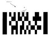
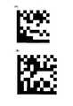
또한, 2차원코드는 정보량에 따라 코드사이즈(code size)가 변경된다. 예를 들면, 셀사이즈(cell size)가 1㎜이고, 코드화한 데이터가 「01234」인 경우, 생성된 2차원코드는 도 28(A)에 나타낸 것이 된다. 도 28(A)에 나타낸 2차원코드는 세로 10셀 × 가로 10셀이고, 전체 사이즈는 10㎜ × 10㎜가 된다. 한편, 코드화한 데이터가 「0123456789」인 경우, 생성된 2차원코드는 도 28(B)에 나타낸 것이 된다. 도 28(B)에 나타낸 2차원코드는 세로 12셀× 가로 12셀이고, 전체 사이즈는 12㎜ × 12㎜가 된다. 이처럼, 2차원코드는 격납된 정보량에 따라 사이즈가 달라지는 것이다.In addition, the code size of the two-dimensional code is changed according to the amount of information. For example, when the cell size is 1 mm and the coded data is "01234", the generated two-dimensional code is shown in Fig. 28A. The two-dimensional code shown in Fig. 28A is 10 cells in length by 10 cells in width, and the overall size is 10 mm by 10 mm. On the other hand, when the coded data is "0123456789", the generated two-dimensional code is shown in Fig. 28B. The two-dimensional code shown in Fig. 28B is 12 cells long x 12 cells wide, and the total size is 12 mm x 12 mm. In this way, the two-dimensional code is sized according to the amount of information stored.
다른 데이터를 같은 사이즈로 마킹하기 위해서 우선 코드사이즈를 지정하고, 원하는 크기의 2차원코드를 형성하는 것을 가능하게 한 기술이 제안되었다.(예를 들면, 특허공개 평11-167602호 공보참조)In order to mark different data in the same size, a technique has been proposed that makes it possible to first specify a code size and to form a two-dimensional code having a desired size (see, for example, Japanese Patent Application Laid-Open No. 11-167602).
그러나, 상기 특허문헌 1의 기술에서는 흑셀(black cell)이 되는 셀에 대해서, 소용돌이꼴의 묘화패턴으로 레이저·마킹을 하기 위해, 레이저장치의 동작제어가 복잡해지는 문제가 있었다. 또한, 코드사이즈를 지정하는 것에 의해 원하는 크기의 2차원코드가 형성가능하지만, 소용돌이꼴의 레이저·마킹을 하기 위해, 지정된 사이즈로 하기 위해서는 레이저의 동작제어를 높은 정밀도로 행할 필요가 있다. 더욱이, 소용돌이꼴의 묘화패턴으로 레이저·마킹을 하기 위해서 초미세한 2차원코드에는 작성이 어려워지는 문제가 있었다.However, the technique of the said
본 발명의 목적은 코드에 기입된 문자나 화상등의 정보량의 많고 적음에 관계없이, 원하는 사이즈의 2차원코드를 간단한 장치구성으로, 높은 정밀도로 형성하는 것이 가능한 2차원코드의 형성방법 및 형성장치를 제공하는 것이다.SUMMARY OF THE INVENTION An object of the present invention is a method and apparatus for forming a two-dimensional code that can form a two-dimensional code having a desired size with a high precision, regardless of a large or small amount of information such as a character or an image written in the code. To provide.
또한, 본 발명의 목적은, 단일의 제품이나, 제품을 구성하는 개개의 부품에 2차원코드를 부여하고, 그 2차원코드를 제조공정에 반영시키는 것에 의해, 불량품의 제조를 효과적으로 방지하는 것이 가능하고, 또한 소비자로부터 품질에 관한 문의나 클레임 등에 대한 회답에 신속히 대응하는 것이 가능한 2차원코드의 형성방법 및 형성장치를 제공하는 것이다.In addition, an object of the present invention is to provide a two-dimensional code to a single product or to individual components constituting the product, and reflect the two-dimensional code in the manufacturing process, thereby effectively preventing the manufacture of defective products. In addition, the present invention provides a method and apparatus for forming a two-dimensional code capable of responding promptly to a customer's inquiries and claims about quality.
상기 과제는 본 발명의 청구항 1에 관련된 2차원코드의 형성방법에 의하면, 2차원코드의 코드사이즈가 지정되는 공정과, 상기 2차원코드에 기입된 격납정보(格納情報)가 지정되는 공정과, 상기 2차원코드를 구성하는 단위셀(unit cell)의 셀사이즈(cell size)가 결정되는 공정과, 상기 단위셀 내 n × n 또는 m × n에 종횡(縱橫)으로 배열된 도트(dot)의 스텝사이즈(step size) 또는 도트개수가 지정되는 공정과, 상기 코드사이즈, 상기 격납정보, 상기 셀사이즈, 상기 스텝사이즈 또는 도트개수에 근거하여 레이저·마킹(laser-marking)정보가 생성되는 공정과, 그 레이저·마킹정보에 근거하여, 2차원코드가 레이저·마킹되는 공정을 구비한 것에 의해 해결된다.According to the method for forming a two-dimensional code according to
상기 단위셀의 셀사이즈는 상기 코드사이즈 및 격납정보에 따라 변화되는 구성이도 좋다.The cell size of the unit cell may vary depending on the code size and the storage information.
또한, 상기 단위셀의 셀사이즈는 미리 결정된 셀수에 근거하여 산출되도록 해도 좋다.The cell size of the unit cell may be calculated based on a predetermined number of cells.
본 발명의 2차원코드의 형성방법에 의하면, 지정된 코드사이즈와, 지정된 정보에 따라 셀사이즈가 결정되고, 그것에 의해 정보량의 대소에 관계없이 지정된 크기의 2차원코드를 형성하는 것이 가능하다. 그리고, 본 발명의 2차원코드의 형성방법으로는, 지정된 스텝사이즈 또는 도트개수에 따라 레이저·마킹되야 할 셀 내를 n행 n열 또는 m행 n열의 방안으로 구획하고, 그 방안내에 도트가 레이저·마킹된다. 이처럼, 단위셀의 레이저·마킹이 도트마킹(dot marking)에 의해 되기 때문에, 마킹부분이 좌우로 튀어나가거나 공백부분이 생기는 등의 마킹오류가 방지된다. 더욱이, 셀사이즈가 변경되는 것에 의해, 같은 크기의 2차원코드에 다른 양의 정보를 격납하는 것이 가능하기 때문에, 마킹부분의 면적에 제한되지 않고, 원하는 정보를 2차원코드로 부여하는 것이 가능하다. 또한, 레이저·마킹이 도트로 되기 때문에 예를 들면, 1셀 1도트로 하면, 극소(極小)사이즈의 2차원코드를 작성하는 것이 가능하다.According to the method for forming a two-dimensional code of the present invention, the cell size is determined in accordance with the designated code size and the designated information, whereby it is possible to form a two-dimensional code having a specified size regardless of the magnitude of the information amount. In the method for forming a two-dimensional code of the present invention, the cell to be laser-marked according to the designated step size or the number of dots is divided into n rows n columns or m rows n columns in which the dots are lasered. Marked. As described above, since the laser marking of the unit cell is performed by dot marking, marking errors such as the marking portion protruding from side to side or the blank portion are generated are prevented. Furthermore, by changing the cell size, it is possible to store different amounts of information in two-dimensional codes of the same size, so that the desired information can be given in two-dimensional code without being limited to the area of the marking portion. . In addition, since the laser marking becomes a dot, it is possible to create a very small two-dimensional code, for example, if one cell is one dot.
또한, 코드사이즈와 셀수를 지정하는 것에 의해, 2차원코드를 구성하는 단위셀이 크기가 통일되기 때문에 독해기는 항상 같은 크기의 셀을 읽어내면 되고, 확실하게 읽어내는 것이 가능하다.In addition, by specifying the code size and the number of cells, the unit cells constituting the two-dimensional code are unified in size, so that the reader can always read cells of the same size and can reliably read them.
또한, 본 발명의 2차원코드의 형성방법은, 단일 혹은 복수의 부품에 의해 구성된 제품에 2차원코드를 형성하는 방법이고, 상기 부품에 대하여 제조이력정보를 취득하는 제조이력정보 취득공정과, 상기 부품에 대한 제조이력정보를 특정하는 식별번호 또는 제조이력정보를 포함한 데이터를 2차원코드화하는 2차원코드화공정과 2차원코드화된 2차원코드의 크기를 상기 부품에 따라 설정하는 파라미터(parameter)설정공정과, 설정된 크기의 2차원코드를 레이저마커(laser marker)에 의해 상기 부품에 직접 레이저·마킹하는 레이저·마킹공정을 구비한 것을 특징으로 한다.The method for forming a two-dimensional code of the present invention is a method for forming a two-dimensional code in a product composed of a single or a plurality of parts, the manufacturing history information acquiring step of acquiring manufacturing history information for the parts, and Two-dimensional encoding process for two-dimensional encoding data including identification number or manufacturing history information specifying manufacturing history information for a part, and parameter setting process for setting the size of two-dimensional coded two-dimensional code according to the part. And a laser marking process for laser-marking the two-dimensional code having a predetermined size directly on the part by means of a laser marker.
이처럼, 단일 혹은 복수의 부품을 조합하여 제조된 제품에 대하여, 그 구성부품에 대한 제조이력정보를 취득하고, 그 제조이력정보에 접근하기 위한 식별번호 또는 제조이력정보를 포함한 데이터를 2차원코드화한 2차원코드의 크기를 부품에 따라 설정하고, 그 설정된 2차원코드를 부품에 직접 레이저마커로 레이저·마킹하고, 마킹된 부품을 조합하여 제품을 제조하기 때문에, 제품에 이상이 있거나 불량부품이 특정되면 그 불량부품에 부여된 2차원코드를 읽는 것에 의해 식별번호를 아는 것이 가능하다.In this way, for a product manufactured by combining a single or a plurality of parts, manufacturing history information on the component is obtained, and data including an identification number or manufacturing history information for accessing the manufacturing history information is two-dimensional coded. Since the size of the 2D code is set according to the part, the set 2D code is laser-marked directly on the part with a laser marker, and the product is manufactured by combining the marked parts. In this case, the identification number can be known by reading the two-dimensional code assigned to the defective part.
그 식별번호를 근거로 제조이력정보에 접근하는 것이 가능하게 된다. 또한, 재료나 제조조건, 완성품질에 관한 대량의 정보를 포함하여 2차원코드로 마킹하는 것에 의해, 별도로 기억된 제조이력정보에 접근하는 일 없이, 직접 그 2차원코드를 읽어내어 품질에 관한 문의나 클레임(claim) 등에 신속히 대응가능하게 된다.It is possible to access manufacturing history information based on the identification number. In addition, by marking a large amount of information on materials, manufacturing conditions, and finished quality with a two-dimensional code, the two-dimensional code can be read directly without access to separately stored manufacturing history information and inquiries about quality. Respond quickly to claims or claims.
그리고, 부품에는 그 크기 등에 따라 2차원코드가 설정되기 때문에, 부품의 크기에 관계없이 2차원코드를 마킹하는 것이 가능하다. 극소(極小)한 사이즈의 부품에 대해서는 2차원코드의 크기를 극소하게 하여 마킹하고, 극대(極大)한 사이즈의 부품에 대해서는 2차원코드의 크기를 자유롭게 설정하여 마킹하면 거의 모든 부품에 대하여 2차원코드를 부여하는 것이 가능하고, 그 코드로부터 제조이력정보로 접근가능하게 된다.Since the two-dimensional code is set according to the size and the like of the part, the two-dimensional code can be marked regardless of the size of the part. For parts of very small size, mark the two-dimensional code with the minimum size, and for parts of the very large size, freely setting and marking the size of the two-dimensional code, it is two-dimensional for almost all parts. It is possible to assign a code, which makes it accessible to manufacturing history information.
또한, 재료나 제조조건, 완성품질에 관한 대량의 정보를 포함하여 2차원코드로 마킹하는 것에 의해, 별도로 기억된 제조이력정보에 접근하는 일 없이, 직접 그 2차원코드를 읽어내어 품질에 관한 문의나 클레임 등에 신속히 대응가능하게 된다.In addition, by marking a large amount of information on materials, manufacturing conditions, and finished quality with a two-dimensional code, the two-dimensional code can be read directly without access to separately stored manufacturing history information and inquiries about quality. It will be possible to respond promptly to claims and claims.
또한 상기 레이저·마킹공정에서는 상기 파라미터설정공정에서 설정된 2차원코드의 크기에 근거하여 상기 2차원코드를, 레이저 빔(laser beam)의 조사(照射)에 의해 형성된 도트를 n × m(단, n, m은 자연수)에 종횡으로 배치하는 단위셀, 레이저 빔의 연속적인 조사에 의해 직사각형상으로 빈틈없이 칠하여 형성하는 단위셀,혹은 레이저 빔의 연속적인 조사에 의해 직사각형상으로 둘러싸이게 형성하는 단위 셀의 어느 것에 의해서도 형성하는 것이 가능하다.In the laser marking process, the dot formed by irradiating a laser beam with the two-dimensional code based on the size of the two-dimensional code set in the parameter setting process is n × m (n m is a unit cell arranged vertically and horizontally in a natural number), a unit cell formed by painting in a rectangular shape by continuous irradiation of a laser beam, or a unit cell formed by being enclosed in a rectangular shape by continuous irradiation of a laser beam. It is possible to form by any of.
이처럼, 2차원코드의 마킹은, 수법의 종류에 따라 행하는 것이 가능하다. 특히, 도트에 의한 마킹(이른바, 도트마킹)은, 셀 내에 도트를 종횡으로 배열하는 것에 의해 균일한 깊이의 셀을 형성하는 것이 가능하기 때문에, 2차원코드의 독해 정밀도를 양호하게 하는 것이 가능하다.In this way, the marking of the two-dimensional code can be performed according to the type of technique. In particular, since marking by dots (so-called dot marking) can form cells of uniform depth by arranging the dots vertically and horizontally in the cells, it is possible to improve reading accuracy of two-dimensional code. .
또한, 상기 레이저·마킹공정에서는, 레이저·마킹한 상기 2차원코드를 읽어내어 상기 2차원코드가 올바르게 마킹되었는지 아닌지를 확인하는 공정을 포함하도록 하면 바람직하다.The laser marking step preferably includes a step of reading the laser-marked two-dimensional code to confirm whether or not the two-dimensional code is correctly marked.
상기 2차원코드의 형성방법을 실현하는 장치는, 2차원코드의 코드사이즈와 상기 2차원코드에 기입된 격납정보와, 상기 2차원코드를 구성하는 단위셀 내 n × m(단, n, m은 자연수)에 종횡으로 배열된 도트의 스텝사이즈 또는 도트개수를 취득하는 정보취득수단과, 상기 코드사이즈 및 격납정보에 근거하여 상기 단위셀의 셀사이즈를 산출하는 처리와, 상기 코드사이즈, 상기 격납정보, 상기 셀사이즈, 상기 스텝사이즈 또는 도트개수에 근거하여 레이저·마킹정보를 생성하는 처리를 행하는 연산수단과, 상기 레이저·마킹정보에 근거하여 2차원코드를 레이저·마킹하는 레이저·마킹수단을 구비한 것을 특징으로 한다.An apparatus for realizing the two-dimensional code forming method includes a code size of a two-dimensional code, storage information written in the two-dimensional code, and n x m in a unit cell constituting the two-dimensional code. Information acquisition means for acquiring the step size or the number of dots of vertically and horizontally arranged dots; processing for calculating the cell size of the unit cell based on the code size and storage information; Calculation means for performing processing for generating laser marking information based on the information, the cell size, the step size or the number of dots; and laser marking means for laser marking two-dimensional codes based on the laser marking information. Characterized in that provided.
상기 연산수단에 있어서, 상기 정보취득수단이 취득한 상기 격납정보의 변경정보에 근거하여, 상기 단위셀의 셀사이즈를 변경하는 처리가 행하여지면, 격납정보가 변경된 경우에 있어서도, 단위셀의 셀사이즈를 변경하는 것에 의해 같은 크기의 2차원코드를 형성하는 것이 가능하게 되어 바람직하다.In the calculation means, if the processing for changing the cell size of the unit cell is performed based on the change information of the storage information acquired by the information acquisition means, the cell size of the unit cell is determined even when the storage information is changed. It is preferable to form a two-dimensional code having the same size by changing it.
또한, 상기 연산수단은, 상기 정보취득수단이 취득한 상기 스텝사이즈 또는 도트개수의 변경정보에 근거하여, 다른 레이저·마킹를 생성하는 처리를 행한다.The calculating means performs processing for generating another laser marking based on the change information of the step size or the number of dots acquired by the information acquiring means.
또한, 2차원코드의 형성장치는, 2차원코드의 코드사이즈와, 상기 2차원코드에 기입된 격납정보와, 상기 2차원코드를 구성하는 단위셀의 셀수와, 상기 2차원코드를 구성하는 단위셀 내 n × m(단, n, m은 자연수)에 종횡으로 배열된 도트의 스텝사이즈 또는 도트개수를 취득하는 정보취득수단과, 상기 코드사이즈 및 셀수에 근거하여 셀사이즈를 산출하는 처리와, 상기 코드사이즈, 상기 격납정보, 상기 셀사이즈, 상기 스텝사이즈 또는 도트개수에 근거하여 레이저·마킹정보를 생성하는 처리를 행하는 연산수단과, 상기 레이저·마킹정보에 근거하여 2차원코드를 레이저·마킹하는 레이저·마킹수단을 구비한 것을 특징으로 한다.The apparatus for forming a two-dimensional code includes a code size of a two-dimensional code, storage information written in the two-dimensional code, the number of cells in a unit cell constituting the two-dimensional code, and a unit constituting the two-dimensional code. Information acquisition means for acquiring the step size or the number of dots arranged vertically and horizontally in n x m (where n and m are natural numbers) in the cell, processing for calculating a cell size based on the code size and the number of cells; Calculation means for performing processing for generating laser marking information based on the code size, the storing information, the cell size, the step size or the number of dots, and laser marking a two-dimensional code based on the laser marking information. And laser marking means.
이때, 상기 연산수단은, 상기 정보취득수단이 취득한 상기 셀수의 변경정보에 근거하여, 상기 단위셀의 셀사이즈를 변경하는 처리를 행하면 셀수가 변경된 경우에 있어서도, 단위셀의 셀사이즈를 변경하는 것에 의해 같은 크기의 2차원코드를 형성하는 것이 가능하게 되어 바람직하다.At this time, the calculating means may change the cell size of the unit cell even when the number of cells is changed if the processing for changing the cell size of the unit cell is performed based on the change information of the number of cells acquired by the information acquiring means. This makes it possible to form two-dimensional codes of the same size.
또한, 상기 연산수단에 있어서, 상기 정보취득수단이 취득한 상기 스텝사이즈 또는 도트개수의 변경정보에 근거하여, 다른 레이저·마킹정보를 생성하는 처리를 행하고, 스텝사이즈 또는 도트개수가 변경된 경우에는, 다른 농도의 2차원코드가 작성된다.Further, in the calculating means, processing for generating other laser marking information based on the change information of the step size or the number of dots acquired by the information acquiring means, and if the step size or the number of dots is changed, Two-dimensional code of density is created.
또한, 본 발명의 2차원코드 형성장치는 단일 혹은 복수의 부품에 의해 구성된 제품에 2차원코드를 형성하는 장치이고, 제품을 구성하는 부품에 대한 제조이력정보를 취득하는 수단과, 취득된 제조이력정보를 기억하는 수단과, 상기 제조이력정보를 특정하는 식별번호 또는 제조이력정보를 포함한 데이터를 2차원코드화하는 수단과, 부품에 따라 설정된 2차원코드의 크기에 근거하여 2차원코드를 부품에 직접 레이저·마킹하는 수단을 구비하는 것을 특징으로 한다.In addition, the two-dimensional code forming apparatus of the present invention is a device for forming a two-dimensional code in a product composed of a single or a plurality of parts, means for acquiring the manufacturing history information for the parts constituting the product, and the acquired manufacturing history Means for storing information, means for two-dimensional coding of data including an identification number or manufacturing history information specifying the manufacturing history information, and a two-dimensional code directly based on the size of the two-dimensional code set in accordance with the component. And a means for laser marking.
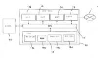
도 1은, 본 발명의 한 실시형태에 관한 레이저·마킹장치의 전체구성을 나타내는 설명도이고,1 is an explanatory diagram showing an overall configuration of a laser marking apparatus according to an embodiment of the present invention.
도 2는, 본 발명의 한 실시형태에 관한 레이저마커의 구성을 나타내는 설명도이고,2 is an explanatory diagram showing a configuration of a laser marker according to an embodiment of the present invention.
도 3은, 2차원코드의 일례를 나타내는 설명도이고,3 is an explanatory diagram showing an example of a two-dimensional code;
도 4는, 2차원코드의 일례를 나타내는 설명도이고,4 is an explanatory diagram showing an example of a two-dimensional code;
도 5는, 도트마킹된 셀의 설명도이고,5 is an explanatory diagram of a dot-marked cell,
도 6은, 벡터마킹(vector marking)된 셀의 설명도이고,6 is an explanatory diagram of a cell marked with vector marking,
도 7은, 도트마킹된 셀의 설명도이고,7 is an explanatory diagram of a dot-marked cell,
도 8은, 벡터마킹된 셀의 설명도이고,8 is an explanatory diagram of a vector marked cell,
도 9는, 2차원코드에 부호화된(encode) 정보의 설명도이고,9 is an explanatory diagram of information encoded in a two-dimensional code,
도 10은, 입력된 정보에 근거하여 작성된 2차원코드의 일례를 나타내는 설명도이고,10 is an explanatory diagram showing an example of a two-dimensional code created based on the inputted information;
도 11은, 같은 코드사이즈에 셀수와 격납정보가 다른 2차원코드를 나타내는 설명도이고,11 is an explanatory diagram showing a two-dimensional code in which the number of cells and the storage information differ in the same code size;
도 12는, 같은 코드사이즈에 셀수와 격납정보가 다른 2차원코드를 나타내는 설명도이고,12 is an explanatory diagram showing a two-dimensional code in which the number of cells and the storage information differ in the same code size;
도 13은, 코드사이즈와 격납정보가 같고 셀수가 다른 2차원코드를 나타내는 설명도이고,13 is an explanatory diagram showing a two-dimensional code having the same code size and storage information and different cell numbers;
도 14는, 2차원코드 작성을 위해 설정입력처리의 흐름을 나타내는 순서도이고,14 is a flowchart showing the flow of setting input processing for creating two-dimensional code;
도 15는, 2차원코드 작성을 위해 설정입력처리의 흐름을 나타내는 순서도이고,15 is a flowchart showing the flow of setting input processing for creating two-dimensional code;
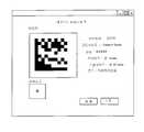
도 16은, 2차원코드 작성을 위해 정보입력화면의 일례를 나타내는 설명도이고,16 is an explanatory diagram showing an example of an information input screen for creating a two-dimensional code;
도 17은, 작성된 2차원코드의 확인화면의 일례를 나타내는 설명도이고,17 is an explanatory diagram showing an example of a confirmation screen of the created two-dimensional code;
도 18은, 작성된 2차원코드의 수정정보입력화면의 일례를 나타내는 설명도이고,18 is an explanatory diagram showing an example of a correction information input screen of a created two-dimensional code;
도 19는, 도트마킹처리를 나타내는 설명도이고,19 is an explanatory diagram showing a dot marking process;
도 20은, 본 발명에 관한 제조이력정보와 부품의 흐름의 설명도이고,20 is an explanatory diagram of the manufacturing history information and the flow of parts according to the present invention;
도 21은, 본 발명에 관한 추적가능성 관리시스템의 설명도이고,21 is an explanatory diagram of a traceability management system according to the present invention;
도 22는, 본 발명에 관한 2차원코드의 설명도이고,22 is an explanatory diagram of a two-dimensional code according to the present invention;
도 23은, 본 발명에 관한 작업공정을 나타내는 설명도이고,23 is an explanatory diagram showing a work process according to the present invention,
도 24는, 본 발명에 관한 다른 추적가능성 관리시스템의 설명도이고,24 is an explanatory diagram of another traceability management system according to the present invention;
도 25는, 본 발명에 관한 셀의 설명도이고,25 is an explanatory diagram of a cell according to the present invention;
도 26은, 본 발명에 관한 2차원코드의 설명도이고,26 is an explanatory diagram of a two-dimensional code according to the present invention;
도 27은, 본 발명에 관한 다른 추적가능성 관리시스템의 설명도이고,27 is an explanatory diagram of another traceability management system according to the present invention;
도 28은, 종래의 예를 나타내는 설명도이다.28 is an explanatory diagram showing a conventional example.
이하, 본 발명의 실시예를 도면에 근거하여 설명한다. 또한, 이하 설명하는 부재, 배치 등은 본 발명을 한정하는 것이 아니고, 본 발명의 취지의 범위 내에서 종류를 개변(改變)하는 것이 가능한 것이다.EMBODIMENT OF THE INVENTION Hereinafter, the Example of this invention is described based on drawing. In addition, the member, arrangement | positioning, etc. which are demonstrated below do not limit this invention, It is possible to change a kind within the range of the meaning of this invention.
본 실시형태에 관련된 2차원코드는, 도트마킹방식에 의해 밝은색 또는 어두운색의 단위셀이 매트릭스상(matrix)으로 배열되어 형성된 것이다. 2차원코드의 형식으로는 데이터매트릭스, QR코드 등을 사용하는 것이 가능하다.In the two-dimensional code according to the present embodiment, light or dark unit cells are formed in a matrix by a dot marking method. It is possible to use a data matrix, QR code, etc. as the format of the two-dimensional code.
도트마킹방식이라는 것은, 피마킹체에 복수의 도트를 형성하는 것에 의해 2차원코드를 작성하는 방식을 나타내고, 본 명세서에 있어서는 레이저·마킹방식 및 인쇄방식의 쌍방을 포함한 것으로 한다.The dot marking method refers to a method of creating a two-dimensional code by forming a plurality of dots on a marked body, and includes both a laser marking method and a printing method in this specification.
도 3 및 도 4에, 2차원코드의 일례를 나타낸다. 2차원코드는 매트릭스상에 배치된 백(白) 또는 흑(黑)의 셀 조합에 의해 명암무늬를 나타내어 데이터를 표시한다. 본 예의 2차원코드 형성장치는 2차원코드를 구성하는 검은셀의 형성에 있어서, 이른바 도트마킹의 수법을 채용한다.3 and 4 show an example of a two-dimensional code. The two-dimensional code expresses the data by expressing the contrast pattern by a combination of white or black cells arranged on the matrix. The two-dimensional code forming apparatus of this example adopts a so-called dot marking method in forming black cells constituting the two-dimensional code.
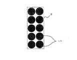
도 3에 나타낸 2차원코드를 도트마킹하는 것에 의해 작성하는 경우는, 단위셀이 정방형(正方形)이기 때문에, 도 5에 나타낸 바와 같이, 검은셀이 되는 단위셀에 대해서, 원형의 도트를 n × m(단, n, m은 자연수)에 종횡으로 레이저·마킹한다. 원형도트는 레이저 빔(laser beam)의 조사위치를 제어하면서 간헐적으로 레이저 빔을 조사는 것에 의해, 셀 내에 도트를 배치해 가는 것이 가능하다. 도트는 평면에서 보아 거의 원형이 아니어도 좋고, 평면에서 보아 거의 직사각형이어도 좋다.In the case where the two-dimensional code shown in FIG. 3 is produced by dot marking, since the unit cells are square, as shown in FIG. Laser marking is carried out vertically and horizontally to m (where n and m are natural numbers). A circular dot can arrange dots in a cell by intermittently irradiating a laser beam, controlling the irradiation position of a laser beam. The dot may be almost circular in plan view or may be almost rectangular in plan view.
또한, 1셀 내에 1개 또는 복수의 도트를 배치하는 것이 아니라, 1셀 내에 들어간 수 이상의 도트를 설정하고, 이른바 벡터마킹(vector mariking)의 수법에 의해 마킹을 하여도 좋다. 벡터마킹은 도 6에 나타낸 바와 같이 도트가 겹쳐지도록 레이저를 조사(照射)하는 것에 의해 형성된다. 혹은 레이저 빔을 연속적으로 조사하면서 레이저 빔의 조사위치를 셀 내에 세로 또는 가로방향으로 조사하는 것에 의해 빔폭을 갖는 선으로 셀을 빈틈없이 칠하는 것에 의해 형성된다.In addition, instead of arranging one or a plurality of dots in one cell, a number of dots or more entered in one cell may be set and marked by a so-called vector mariking method. Vector marking is formed by irradiating a laser so that dots overlap as shown in FIG. Alternatively, by irradiating the laser beam with a vertical or horizontal direction while irradiating the laser beam continuously, the cell is formed by seamlessly painting the cell with a line having a beam width.
또한, 도 4에 나타낸 2차원코드를 도트마킹에 의해 작성하는 경우는 단위셀이 장방형(長方形)이기 때문에, 도 7에 나타낸 바와 같이 검은셀이 되는 단위셀에 대해서, 원형도트를 n × m(단, n, m은 자연수)에 종횡으로 레이저·마킹한다. 이때, 도 8에 나타낸 바와 같이, 벡터마킹을 하여도 좋다.In addition, when the two-dimensional code shown in FIG. 4 is produced by dot marking, since the unit cells are rectangular, as shown in FIG. However, n and m are laser-marked vertically and horizontally to a natural number). At this time, as shown in FIG. 8, vector marking may be performed.
도 1은, 본 실시형태에 관한 레이저·마킹장치의 전체구성을 나타낸 설명도이다.1 is an explanatory diagram showing an overall configuration of a laser marking apparatus according to the present embodiment.
그 레이저·마킹장치는 2차원코드, 문자, 도형, 신호, 화상등의 마킹패턴(marking pattern)을 워크(work, 피마킹체, W)에 마킹하는 것에 바람직하게 사용되는 것이고, 주로 데이터제어장치(10)와 레이저마커(40)로 구성된다.The laser marking apparatus is suitably used for marking marking patterns such as two-dimensional codes, characters, graphics, signals, and images on a work (marked body) W, and mainly a data control apparatus. 10 and the
데이터제어장치(10)는 각종 제어를 행하는 CPU(11)와 키보드나 마우스 등으로 구성되는 입력부(12)와, 모니터나 액정화면 등으로 구성되는 표시부(13)와, 프린터나 전자기억매체로의 입출력장치 등으로 구성되는 출력부(14)와 모뎀 등으로 구성된 입출력부(15)와, HDD나 메모리 등으로 구성되는 기억부(16)를 구비하고 있다. 기억부(16)에는 제어프로그램(16a), 작업영역으로 사용되는 RAM(16b), 다음에 서술하는 추적가능성 관리에 있어서 부품(72)의 제조이력정보를 기억하는 데이터베이스(16c), 레이저·마킹할 때의 각종 파라미터(parameter)를 기억하는 파라미터정보(16d)가 격납된다.The data control
또한, 데이터베이스(16c)를 별도의 장치 내에 격납하고, 데이터제어장치(10)에서 데이터베이스(16c)에 접근가능하게 하는 구성으로도 좋다. 또한, 품질이나 클레임 등의 문의에 대응할 때 데이터베이스(16c)를 다시 복제해서 도시하지 않은 외부장치에 기억시키는 구성으로 하는 것도 가능하다.It is also possible to store the
더욱이, 기억부(16)에는 입출력부(15)에서 입력된 정보로서, 코드사이즈, 코드에 기입한 격납정보, 코드를 구성하는 단위셀에 배열된 도트의 스텝사이즈, 피마킹재의 정보 등의 정보가 격납된다. 스텝사이즈라는 것은 마킹재에 레이저·마킹된 도트의 중심간거리(中心間距離)이다. 또한, 셀수가 일정하게 된 경우에는, 입출력부(15)에 셀수에 관한 정보가 입력된다. 또한, 입력정보에 대해서는 2차원코드 작성을 위한 설정입력의 설명에 있어서 상세히 설명한다.Further, the information input from the input /
또한, 입출력부(15)는 통신회로망(I)과 접속되어 있고, 데이터제어장치(10)는 외부의 통신단말에서 통신회로망(I)을 통해서 부품의 제조이력정보 등의 각종 정보를 수신하는 것이 가능하다. 또한, 데이터제어장치(10)에서 통신회로망(I)을 통해 상기 통신단말에 접근하여 제조이력정보를 다운로드하고, 데이터베이스(16c)에 격납해도 좋다.In addition, the input /
CPU(11)는 제어프로그램(16a)에 근거하여, 입출력부(15)를 통하여 수신한 부품(72)의 제조이력정보를 기억부(16)의 데이터베이스(16c)에 격납한다. 또한, CPU(11)는 손으로 입력된 데이터나 전자매체에 기억된 데이터를 입력부(12)로 부터 받아들여, 데이터베이스(16c)에 격납하는 것이 가능하다. CPU(11)는 조작자의 조작입력에 근거하여, 데이터베이스(16c)에서 기억하고 있는 데이터를 2차원코드화 하고 순서단말(sequence terminal, 20)을 통해 데이터제어장치(10)에 대하여 마킹하기 위한 제어신호를 송신한다.The
도 2에, 레이저마커(laser marker, 40)의 구성을 나타낸다. 레이저마커(40)는 데이터제어장치(10)로부터의 제어신호에 따라 소정의 깊이를 유지하면서 동시에, 예를 들면 평면상에서 보아 원형의 도트를 부품(72)에 마킹하기 위해 컨트롤러(42)가 초음파 Q스위치소자(43), 내부셔터(44), 외부셔터(45), 광감쇠기(attenuator, 46) 및 갈바노미러(Galrvanomirror, 47)를 제어하고, 1개의 도트에 대해서 1회 또는 복수회 Q스위치펄스(Q switch pulse)로 마킹한다.2 shows the configuration of a
또한, 같은 도면 중의 부호(51)는 모두 반사경, 부호(52)는 내부 애퍼추어(aperture, 모드셀렉터), 부호(53)는 램프하우스(lamp house), 부호(54)는 출력경(出力鏡), 부호(55)는 애퍼추어, 부호(56)는 레벨링미러(leveling mirror), 부호(57)는 갈릴레오식 익스팬더(expander), 부호(58)는 애퍼추어, 부호(59)는 f-θ렌즈, 부호(50)는 레이저발진기이다.In the same drawing, all the
CPU(11)는 프로그램에 따라 소요 데이터처리를 행하고, 장치 내의 각 부분을 제어한다. 본 예의 CPU(11)는 지정된 코드사이즈와 격납정보, 또는 지정된 코드사이즈와 셀수에 근거하여 셀사이즈를 산출하는 처리를 행한다. 또한, 지정된 코드사이즈, 격납정보, 셀사이즈, 스텝사이즈에 근거하여, 레이저마커(40)가 레이저·마킹을 하기 위한 레이저·마킹정보를 작성하는 처리를 행한다. 더욱이, 격납정보나 스텝사이즈에 변경이 있는 경우에는 변경정보에 근거하여 레이저·마킹정보의 변경처리를 행한다.The
CPU(11)는 지정된 사이즈로 2차원코드를 작성하기 위한 연산을 행한다. CPU(11)는 지정된 코드사이즈와 격납된 정보량, 또는 지정된 코드사이즈와 셀수에 근거하여, 2차원코드를 구성하는 셀의 사이즈를 산출한다. 지정된 코드사이즈와 격납된 정보량으로부터 셀사이즈를 산출하는 경우, 셀사이즈는 지정된 코드사이즈를, 격납정보를 2차원코드에 부호화한 때의 코드수로 나누는 것에 의해 구해진다.The
예를 들면, 코드사이즈가 5㎜ × 5㎜로 지정되고, 격납된 정보가 「01234」이라고 한다. 이 경우, 「01234」를 2차원코드에 부호화하면, 도면 9에 나타낸 바 와 같이, 세로 10개 × 가로 10개의 0 또는 1의 숫자로 표시된다. 이때의 셀사이즈는 세로 5㎜/10개=0.5㎜, 가로 5㎜/10개=0.5㎜로 구해진다.For example, the code size is designated 5 mm x 5 mm, and the stored information is "01234". In this case, when " 01234 " is encoded in a two-dimensional code, as shown in Fig. 9, it is represented by a number of 10 or 10 horizontal 0 or 1 numerals. The cell size at this time is calculated | required as 5 mm / 10 pieces = 0.5 mm, and 5 mm / 10 pieces = 0.5 mm.
코드사이즈와 셀수가 지정된 경우, 셀사이즈는 지정된 코드사이즈를 셀수로 나누는 것에 의해 구해진다. 예를 들면, 코드사이즈는 5㎜ × 5㎜로 지정되고, 셀수가 세로 20개 × 가로 20개로 지정된 경우, 셀사이즈는 세로 5㎜/20개=0.25㎜, 가로 5㎜/20개=0.25㎜로 구해진다.If the code size and the number of cells are specified, the cell size is obtained by dividing the specified code size by the number of cells. For example, when the code size is specified as 5 mm x 5 mm, and the number of cells is specified as 20 by 20 by 20 cells, the cell size is 5 mm / 20 pieces = 0.25 mm and 5 mm / 20 pieces = 0.25 mm Obtained by
더욱이, CPU(11)는 각 셀에 레이저·마킹된 도트의 스텝사이즈에 관한 정보를 취득하고, 코드사이즈, 격납정보, 셀사이즈, 스텝사이즈에 근거하여, 레이저·마킹정보를 생성한다. 레이저·마킹정보라는 것은 레이저마커(40)에 대하여, 피마킹재에 대해 어떻게 마킹하는가를 지시하는 정보이고, 도트의 좌표정보와, 레이저파장, Q스위치주파수, 레이저의 파워, 도트밀도, 도트조사시간, 마킹횟수 등의 파라미터정보를 포함한 것이다.Further, the
CPU(11)에서 작성된 레이저·마킹정보는 레이저마커(40)로 송부된다. 레이저마커(40)측에서는 송부된 레이저·마킹정보에 근거하여, 컨트롤러에 의해 각 부위의 제어가 이루어지고, 레이저·마킹정보에 따른 레이저·마킹이 된다. 레이저마커(40)는 수신한 레이저·마킹정보로부터 각 도트의 좌표정보를 읽어내고, 그 좌표정보에 근거하여, 피마킹재에 대하여 레이저·마킹을 한다.The laser marking information generated by the
도 10은, 사용자에 의해 입력된 정보에 근거하여 작성된 2차원 코드의 예를 나타낸다. 도시된 2차원코드는 사용자에 의해 지시된 코드사이즈가 세로 5㎜ × 가로 5㎜이고, 입력된 정보량에 따라 산출된 셀사이즈가 0.5㎜ × 0.5㎜이고, 레이저 ·마킹에 의해 형성된 도트지름이 0.05㎜이고, 사용자에 의해 지시된 스텝사이즈가 0.1㎜라는 것이다.10 shows an example of a two-dimensional code created based on information input by a user. In the illustrated two-dimensional code, the code size instructed by the user is 5 mm long x 5 mm long, the cell size calculated according to the input information amount is 0.5 mm x 0.5 mm, and the dot diameter formed by laser marking is 0.05. Mm, and the step size indicated by the user is 0.1 mm.
또한, 본 발명의 2차원 코드의 형성방법에 의하면, 도 11(A), (B), (C)에 나타낸 바와 같이, 2차원코드에 포함된 데이터량의 대소에 상관없이, 2차원코드의 사이즈를 일정하게 하는 것이 가능하다. 즉, 도 11(A)과 같이 데이터량이 작은 경우에는, 2차원코드를 구성하는 전체의 셀수는 적어지지만 단위셀의 사이즈는 커진다. 이 경우, 단위셀은 6 × 6에 배열된 도트에 의해 구성된다. 한편, 도 11(B)과 같이 데이터량이 큰 경우에는, 2차원코드를 구성하는 전체의 셀수는 많아지지만 단위셀의 사이즈는 작아진다. 이 경우, 단위셀은 3 × 3에 배열된 도트에 의해 구성된다. 또한, 도 11(A), (B)에서, 각 도트의 사이즈 및 스텝사이즈는 동일하게 설정된다.According to the method for forming a two-dimensional code of the present invention, as shown in Figs. 11A, 11B and 11C, regardless of the magnitude of the data amount included in the two-dimensional code, It is possible to make the size constant. In other words, when the data amount is small as shown in Fig. 11A, the total number of cells constituting the two-dimensional code is small, but the size of the unit cell is large. In this case, the unit cell is composed of dots arranged in 6x6. On the other hand, when the data amount is large as shown in Fig. 11B, the total number of cells constituting the two-dimensional code increases, but the size of the unit cell decreases. In this case, the unit cell is composed of dots arranged in 3x3. 11 (A) and (B), the size and step size of each dot are set the same.
이처럼, 데이터량의 대소에 관계없이 2차원코드의 사이즈를 일정하게 하는 것이 가능하기 때문에, 한정된 마킹스페이스(marking space) 밖에 없는 경우에도, 데이터량에 의해 2차원코드의 사이즈가 커질 일이 없어서, 필요한 데이터를 확실하게 2차원코드에 포함하는 것이 가능하다. 또한, 상기 실시형태는 도트사이즈 및 스텝사이즈를 일정하게 한 예이지만, 도트사이즈 및 스텝사이즈를 변경하여 단위셀을 적절하게 설정하는 것은 물론 가능하다. 예를 들면, 도 12(A)에 나타낸 바와 같이, 1셀에 3 × 3의 도트가 배치된 경우에 있어서, 스텝사이즈를 작게 하는 것에 의해, 도 12(B)에 나타낸 바와 같이, 셀사이즈를 작은 것으로 하는 것이 가능하다. 이처럼, 스텝사이즈를 변경하는 것에 의해 단위셀 수의 증감에 대응하는 것이 가능하다.In this way, since the size of the two-dimensional code can be made constant regardless of the magnitude of the data amount, even if there is only a limited marking space, the size of the two-dimensional code does not increase, It is possible to reliably include the necessary data in the two-dimensional code. The above embodiment is an example in which the dot size and the step size are made constant, but it is of course possible to set the unit cell appropriately by changing the dot size and the step size. For example, as shown in Fig. 12 (A), in the case where 3x3 dots are arranged in one cell, the cell size is reduced as shown in Fig. 12B by decreasing the step size. It is possible to make small. In this way, it is possible to cope with the increase or decrease of the number of unit cells by changing the step size.
또한, 스텝사이즈를 변경하면, 스텝사이즈가 커짐에 따라, 도트밀도가 거칠어지기 때문에 코드의 농도를 엷게 하는 것이 가능하다. 또한, 스텝사이즈가 작아짐에 따라 도트밀도는 빽빽해지기 때문에, 코드의 농도를 높이는 것이 가능하다. 이처럼, 같은 2차원코드에 있어서도, 스텝사이즈의 대소에 의해, 코드농도의 조정을 행하는 것이 가능하다.In addition, if the step size is changed, the dot density becomes coarse as the step size increases, so that the code density can be reduced. In addition, as the step size becomes smaller, the dot density becomes dense, so that the code density can be increased. In this way, even in the same two-dimensional code, the code concentration can be adjusted by the size of the step size.
또한, 스텝사이즈를 0(zero)으로 한 경우, 즉, 도 11(C)에 나타낸 바와 같이 1셀 1도트로 한 경우는, 셀사이즈를 작게 하는 것에 의해 단위셀 수를 증가시키는 것이 가능하고, 2차원 코드에 의해 많은 정보를 격납하는 것을 가능하다. 이 상태에서 도트사이즈를 작게 하면, 단위셀 수를 더욱 증가하는 것이 가능하고, 많은 정보를 격납하는 것이 가능하게 된다. 그리고 1셀에 1도트로 레이저·마킹을 하는 것에 의해, 2차원코드의 형성을 고속으로 행하는 것이 가능하게 된다.In addition, when the step size is 0 (zero), that is, when one cell is one dot as shown in Fig. 11C, the number of unit cells can be increased by reducing the cell size. It is possible to store a lot of information by two-dimensional code. When the dot size is reduced in this state, the number of unit cells can be further increased, and a large amount of information can be stored. By laser marking at one dot per cell, formation of a two-dimensional code can be performed at high speed.
또한, 1셀 1도트로 한 경우는, 단위셀을 인식가능할 정도로 단위셀 내에 도트마킹될 필요가 있다. 즉, 셀사이즈가 커짐에 따라, 단위셀 내에 형성된 도트도 커질 필요가 있다. 이렇기 때문에 피마킹재의 소재 및 셀사이즈에 따라, 레이저파장, 레이저의 파워, Q스위치주파수, 도트조사시간, 마킹횟수 등의 최적값를 지정하거나, 혹은 레이저마커(40)에 있는 렌즈를 교환하여, 단위셀 내에 적정한 크기의 도트가 형성되도록 하여도 좋다.In addition, in the case where one cell is one dot, it is necessary to dot mark the unit cells to the extent that the unit cells can be recognized. That is, as the cell size increases, the dots formed in the unit cell also need to increase. For this reason, depending on the material and cell size of the marked material, an optimum value such as laser wavelength, laser power, Q switch frequency, dot irradiation time, marking frequency, or the like is replaced, or the lens in the
도 13은, 도트사이즈와 셀수가 미리 결정된 2차원코드를 나타낸 설명도이다. 도 13(a)와 도 13(b), 도13(c)와 도 13(d)는, 코드사이즈와 격납정보가 같지만, 셀수가 다르다. 즉, 도 13(a)와 도 13(b)에는 「01234」라는 같은 정보가 격납되어 있는데, 도 13(a)의 셀수는 세로 10개× 가로 10개, 도 13(b)의 셀수는 세로 22개× 가로 22개이다. 또한, 도 13(c)와 도 13(d)에는 「0123456789」라는 같은 정보가 격납되어 있는데, 도 13(c)의 셀수는 세로 10개× 가로 10개, 도 13(d)의 셀수는 세로 22개× 가로 22개이다. 이처럼, 2차원코드는, 셀수가 미리 정해진 경우, 지정된 셀수의 범위에서 같은 정보에 관한 표시를 행하는 것이 가능하다. 단, 셀수가 지정된 경우, 격납된 정보량의 상한(上限)에 제약이 발생한다.13 is an explanatory diagram showing a two-dimensional code in which the dot size and the number of cells are predetermined. 13 (a), 13 (b), 13 (c) and 13 (d) have the same code size and stored information, but differ in the number of cells. That is, the same information " 01234 " is stored in Figs. 13A and 13B, and the number of cells in Fig. 13A is 10 x 10 times, and the number of cells in Fig. 13B is vertical. 22 pieces x 22 pieces. In addition, the same information "0123456789" is stored in Figs. 13 (c) and 13 (d), and the number of cells in Fig. 13 (c) is 10 vertical × 10 horizontal, and the number of cells in Fig. 13 (d) is vertical. 22 pieces x 22 pieces. In this way, when the number of cells is predetermined, the two-dimensional code can display the same information in the range of the specified number of cells. However, when the number of cells is specified, a restriction is placed on the upper limit of the amount of stored information.
2차원코드를 형성할 때에 셀수를 지정하는 것에 의해, 정보량의 많고 적음에 상관없이, 항상 같은 셀수의 2차원코드로 하는 것이 가능하다. 따라서, 2차원코드를 읽어낼 때에 독해기 측에서 항상 같은 셀사이즈의 코드를 읽어내면 좋고, 읽기를 행할 때의 조정이 용이함과 동시에, 확실하게 데이터를 읽어내는 것이 가능하게 된다.By specifying the number of cells when forming the two-dimensional code, it is possible to always make the two-dimensional code of the same number of cells irrespective of the large or small amount of information. Therefore, when reading the two-dimensional code, the reader should always read the code having the same cell size, making it easy to adjust the reading and making it possible to read the data reliably.
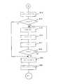
여기서, 본 예에 있는 2차원코드 작성을 위한 설정입력에 대하여 설명한다. 도 14 및 도 15는, 설정입력에서 CPU(11)의 처리를 순서도로 나타낸다. 설정입력을 할 때는, 데이터제어장치(10)의 표시부(13)에 도 16에 나타낸 입력화면이 표시된다. 입력화면에는 피마킹재의 소재에 관한 정보입력부(N1), 코드사이즈 및 셀수에 관한 정보입력부(N2), 격납정보에 관한 정보입력부(N3), 스텝사이즈에 관한 정보입력부(N4)가 설치되어 있고, 각각의 정보가 입력된다. 정보입력부(N4)에는 피마킹재의 소재와 레이저·마킹을 할 때의 조건에 따라, 스텝사이즈의 적정값이 표시된다. 스텝사이즈로, 예를 들면 금속면에 0.003㎜ 지름의 도트가 형성되는 레이저·마킹인 경우, 세라믹이면 0.005㎜ ~ 0.01㎜, 수지(樹脂)이면 0.01㎜ ~ 0.02㎜, 페인트의 도장면(塗裝面)이면 0.01㎜ ~ 0.02㎜, 알루미늄이면 0.003㎜ ~ 0.01㎜, 스테인리스(stainless steel)이면 0.003㎜ ~ 0.01㎜, 유리이면 0.006㎜ ~ 0.02㎜, 종이이면0.006㎜ ~ 0.02㎜가 적정값으로 제시된다. 사용자는 적정값을 참조하면서 소정의 스텝사이즈를 입력한다.Here, setting input for creating two-dimensional code in this example will be described. 14 and 15 show a flowchart of the processing of the
예를 들면, 피마킹재가 세라믹인 경우, 도트의 밀도를 높게 하여 진하게 마킹을 하고 싶은 경우는, 스텝사이즈 0.005㎜가 지정되고, 도트의 밀도를 낮게 하여 엷게 마킹하고 싶은 경우에는 스텝사이즈 0.01㎜가 지정된다. 스텝사이즈는, 적정값의 범위 내에 한정하지 않고, 범위 외의 수치도 지정가능하다. 예를 들면, 스텝사이즈가 0(zero)인 경우는 도 8(C)에 나타낸 바와 같이, 1셀에 1도트로 레이저·마킹이 이루어진다.For example, in the case where the marked material is ceramic, when the density of the dots is to be increased and the marking is made thick, a step size of 0.005 mm is specified, and when the density of the dots is to be reduced and lightly marked, the step size is 0.01 mm. Is specified. Step size is not limited to the range of an appropriate value, The numerical value outside a range can also be specified. For example, when the step size is 0 (zero), as shown in Fig. 8C, laser marking is performed with one dot in one cell.
피마킹재의 소재로는, 세라믹, 수지(樹脂), 도장면(塗裝面), 알루미늄, 실리콘, 유리, 스테인리스, 종이, 목재, 피혁, 직물, 보석 등이 있다. 우선 단계(S1)에서 소정의 소재가 선택되었는지 아닌지가 판정된다. 소정의 소재가 선택된 것이 확인되면(단계 S1 ; 예), CPU(11)는 기억부(16)에 격납된 파라미터정보로부터 레이저·마킹을 할 때의 조건을 읽는다(단계 S2). 소정의 소재가 선택된 것이 확인되지 않은 경우(단계 S1 ; 아니오), 확인될 때까지 처리를 반복한다.Examples of the material for the marked material include ceramics, resins, painted surfaces, aluminum, silicon, glass, stainless steel, paper, wood, leather, textiles, and jewelry. First, in step S1, it is determined whether or not a predetermined material is selected. If it is confirmed that the predetermined material is selected (step S1; YES), the
이어서, 단계(S3)에서 코드사이즈가 지정되었는지 아닌지가 판정된다. 코드사이즈를 지정하기 위해서는 사용자에 의해, 도 13에 나타낸 표시화면에 있어서, 코드사이즈에 관한 정보입력부(N2)에 폭과 높이의 수치가 각각 입력된다. 코드사이즈가 지정된 경우(단계 S3 ; 예), 입력된 데이터는 데이터제어장치(10)로 받아들여지고, 기억부(16)에 격납됨과 동시에 CPU(11)에 의해 인식된다(단계 S4). 코드사이즈의 지정이 확인되지 않은 경우(단계 S3 ; 아니오), 확인될 때까지 처리를 반복한다.Then, it is determined whether or not the code size is specified in step S3. In order to designate the code size, the user inputs numerical values of the width and the height into the information input section N2 relating to the code size on the display screen shown in FIG. If the code size is specified (step S3; yes), the input data is received by the
그리고, 단계(S5)에서 2차원코드에 기입된 정보가 입력되었는지 아닌지가 확인된다. 격납정보가 입력된 경우(단계 S5 ; 예), 입력된 데이터는 데이터제어장치(10)로 받아들여지고, 기억부(16)에 격납됨과 동시에 CPU(11)에 의해 확인된다(단계 S6).Then, in step S5, it is checked whether or not the information written in the two-dimensional code has been input. When the storage information is input (step S5; YES), the input data is received by the
이어서, 단계(S7)에서, 셀수가 지정되었는지 아닌지가 확인된다. 셀수가 지정된 경우(단계 S7 ; 예), 입력된 데이터는 데이터제어장치(10)로 받아들여지고, 기억부(16)에 격납됨과 동시에 CPU(11)에 의해 확인된다(단계 S8). 셀수가 지정되지 않은 경우(단계 S7 ; 아니오), 단계(S9)로 진행한다.Next, in step S7, it is checked whether or not the number of cells is specified. If the number of cells is specified (step S7; YES), the input data is received by the
단계(S9)에서는 2차원코드를 구성하는 셀수를 산출한다. 단계(S7)에서 셀수가 지정된 경우에는, 코드사이즈와 셀수에 근거하여 셀사이즈를 산출한다. 단계(S7)에서 셀수가 지정되지 않은 경우는, 코드사이즈와 격납정보에 근거하여 셀사이즈를 산출한다.In step S9, the number of cells constituting the two-dimensional code is calculated. If the number of cells is specified in step S7, the cell size is calculated based on the code size and the number of cells. If the number of cells is not specified in step S7, the cell size is calculated based on the code size and the storing information.
이어서, 단계(S10)에서는 스텝사이즈가 지정되었는지 아닌지가 판정된다(단계 S10). 스텝사이즈가 지정된 경우(단계 S10 ; 예), 그 정보가 데이터제어장치(10)로 받아들여지고, 기억부(16)에 격납됨과 동시에 CPU(11)에 의해 확인된다(단계 S11). 또한, 스텝사이즈가 지정되지 않은 경우(단계 S10 ; 아니오), 표준의 농도로 형성하는 것으로 판정되어 적정범위의 중간값이 설정되어 단계(S12)로 진행한다.Next, in step S10, it is determined whether or not the step size is designated (step S10). If the step size is specified (step S10; yes), the information is received by the
단계(S12)에서 CPU(11)는, 코드사이즈, 격납정보, 셀사이즈, 스텝사이즈에 따라 레이저마커(40)가 레이저·마킹을 하기 위한 레이저·마킹정보를 형성한다.In step S12, the
단계(S13)에서는, 상기 공정에 의해 결정된 2차원코드가 데이터제어장치(10)의 표시부(13)에 표시된다. 이때, 표시부(13)에는 예를 들면, 도 17에 나타낸 바와 같은 화면이 표시된다. 이러한 표시부(13)로의 표시는 설정이 종료된 시점에서 자동적으로 행해져도 좋고, 혹은 사용자로부터 미리보기(preview)의 요청이 있는 경우에만 표시하도록 하여도 좋다. 사용자는 표시부(13)를 보고, 이 2차원코드로 좋은지 아닌지를 검토한다. 단계(S14)에서는 격납정보 또는 스텝사이즈에 대하여 수정이 필요한지 아닌지가 판정된다. 수정 등이 없이 사용자에 의해 OK버튼이 클릭된 경우는(단계 S14 : 아니오), 단계(S20)로 진행한다. 한편, 사용자에 의해 수정요청이 있어(단계 S14 : 예), 격납정보 또는 스텝사이즈에 대하여 수정정보가 입력된 경우는 그 수정정보가 데이터제어장치(10)로 인식되고, 도 18에 나타낸 수정화면이 표시된다(단계 S15).In step S13, the two-dimensional code determined by the above process is displayed on the
수정화면에서는 격납정보나 스텝사이즈의 수정정보가 입력된다. 수정정보가 입력되면, 그 정보가 데이터제어장치(10)로 받아들어지고, 기억부(16)에 격납됨과 동시에 CPU(11)에 의해 확인된다(단계 S16).In the correction screen, the storage information and the correction information of the step size are input. When the correction information is input, the information is received by the
수정화면에는 사용자로부터 변경지시가 있을 때마다 표시된 2차원코드가 변경되도록 하면, 사용자는 2차원코드의 상태를 확인하면서 수정처리가 가능하게 되어 바람직하다.If the displayed two-dimensional code is changed every time there is a change instruction from the user, the user can preferably perform a modification process while checking the state of the two-dimensional code.
그리고, 수정처리가 이루어지고(단계 S17), 수정이 완료되었는지 아닌지가 판정된다(단계 S18). 수정이 완료되지 않은 경우는(단계 S18 ;아니오), 단계(S15) ~ 단계(S17)의 처리를 반복한다. 수정이 완료되었다고 판정된 때에는(단계 S18 ; 예), CPU(11)는 단계(S19)에서 변경된 격납정보 및 스텝사이즈에 근거하여, 레이저·마킹정보를 수정한다. 그리고, 단계(S20)에서 상기 레이저·마킹정보가 레이저마커측으로 송출된다. 레이저마커(40)의 컨트롤러(42)는 송부된 정보에 근거하여, 초음파 Q스위치소자(43), 내부셔터(44), 외부셔터(45), 광감쇠기(46), 갈바노미러(47)를 제어하고, 피마킹재의 위에 소정의 2차원코드를 레이저·마킹에 의해 형성한다. 레이저·마킹을 할 때에는 도 19(A)에 나타낸 순서로 마킹을 한다. 또한 각 셀 내의 마킹은 도 19(B)에 나타낸 방향으로 도트마킹을 한다.Then, a correction process is made (step S17), and it is determined whether or not the correction is completed (step S18). If the correction is not completed (step S18; no), the processing of steps S15 to S17 is repeated. When it is determined that the correction is completed (step S18; YES), the
이처럼, 본 발명의 2차원코드의 형성방법에 의하면, 소정의 코드사이즈로, 예를 들면, 셀수를 10 × 10으로 한 경우, 숫자면 6문자, 영숫자이면 3문자, 2진법(binary)의 경우는 1문자를 격납하는 것이 가능하다. 그리고 같은 코드사이즈라도 셀수를 144 × 144로 한 경우, 숫자면 3116문자, 영숫자이면 2335문자, 2진법(binary)의 경우는 1556문자처럼 확대한 정보를 격납하는 것이 가능하다. 따라서 마킹하는 공간이 한정되는 장소라도, 작은 공간에 많은 정보를 기입하는 것이 가능하다. 또한, 단위셀 안에 검은셀이 되는 것이 도트마킹에 의해 형성되기 때문에, 도트간거리인 스텝사이즈를 조정하는 것에 의해, 어떠한 크기의 셀에도 대응하는것이 가능하다. 또한 스텝사이즈를 조정하는 것에 의해, 원하는 농도로 2차원코드를 형성하는 것이 가능하다.Thus, according to the formation method of the two-dimensional code of the present invention, in the case of a predetermined code size, for example, the number of cells is 10 × 10, 6 characters if the number, 3 characters if the alphanumeric, binary case (binary) Can contain one character. Even in the same code size, it is possible to store expanded information such as 3116 characters for numbers, 2335 characters for alphanumeric characters, and 1556 characters for binary numbers. Therefore, even in a place where the marking space is limited, it is possible to write a lot of information in a small space. Further, since black cells in the unit cells are formed by dot marking, it is possible to correspond to cells of any size by adjusting the step size which is the distance between dots. By adjusting the step size, it is possible to form a two-dimensional code at a desired density.
또한, 본 예에서 2차원코드는 피마킹재에 직접 양호한 상태로 레이저·마킹된다. 그래서, 별도의 부재에 인쇄된 2차원코드를 부착하거나, 인쇄에 의해 형성하는 경우에 비하여, 몇 년이 지나 벗겨지거나 흐려지거나 하는 일이 발생하지 않고, 장기간동안 이동정보를 보호 유지하는 것이 가능하다.In this example, the two-dimensional code is laser-marked in a good state directly on the marked material. Therefore, compared to the case where the printed two-dimensional code is attached to a separate member or formed by printing, it is possible to protect the moving information for a long time without causing peeling or blurring after several years. .
또한, 도트마킹이기 때문에 피마킹재에 연속적으로 레이저·마킹되는 벡터마킹에 비하여, 레이저·마킹을 할 때에 마킹부분에 연속적으로 미세한 흠 등이 발생하는 일 없이, 대기후성(對候性), 내식성(耐蝕性), 대충격성(對衝擊性)에 뛰어나고, 어떠한 소재라도 바람직하게 2차원코드를 부여하는 것이 가능하다. 특히, 유리 등의 투명소재에 레이저·마킹을 하는 경우, 투명소재에 마킹을 했을 때에 발생하는 갈라진 금(crack)이 도트 흔적 안에 봉해져 도트마킹으로 형성된 2차원코드의 범위 외에 갈라진 금이 발생하지 않아 바람직하다. 또한 금속소재로 마킹을 할 때에는 도트 흔적의 심도(深度)를 1㎛에서 20㎛의 사이로 하고, 도장면에 마킹을 할 때에는 도트 흔적의 심도를 1㎛에서 10㎛의 사이로 하는 것에 의해, 피마킹재의 열화(劣化)를 방지하는 것이 바람직하다.In addition, since it is a dot marking, compared with the vector marking which is laser-marked continuously to a marked material, it does not generate | occur | produce minute flaws etc. continuously in a marking part at the time of laser marking, and it has a weather resistance and corrosion resistance. It is excellent in stiffness and impact resistance, and any material can be preferably given a two-dimensional code. In particular, when laser marking a transparent material such as glass, cracks generated when the transparent material is marked are sealed in a dot trace so that cracks do not occur outside the range of a two-dimensional code formed by dot marking. desirable. In addition, when marking with a metal material, the depth of the dot trace is set to 1 micrometer-20 micrometers, and when marking a coating surface, the depth of a dot trace is set to 1 micrometer-10 micrometers, and is marked. It is desirable to prevent deterioration of the ash.
상기 실시예에는 도트의 밀도를 결정하기 위해 스텝사이즈를 지정하는 방법을 나타냈지만, 스텝사이즈가 아니라 도트의 개수를 지정하는 방법으로도 좋다. 스텝사이즈와 도트수는 상관관계에 있고, 어떤 것이 일단 정해지면 다른 것도 결정된다.In the above embodiment, a method of designating a step size for determining the density of dots is shown. However, the method may be used to designate the number of dots instead of the step size. The step size and the number of dots are correlated, and once something is determined, another is determined.
더욱이, 상기 실시예에는 정보량의 많고 적음에 따라 셀사이즈가 변화하는 경우, 단위셀 내의 도트의 스텝사이즈를 변경하는 것에 의해 대응하는 예를 나타냈 다. 또한, 도트마킹이 아니라, 세로로 n개 가로로 m개의 직선으로 마킹하는 벡터마킹이 이루어진 경우는, 직선의 길이를 변경하거나, 혹은 직선의 개수를 변경하는 것에 의해 셀의 크기를 조종하는 것도 좋다.Furthermore, in the above embodiment, when the cell size changes due to the large or small amount of information, a corresponding example is shown by changing the step size of the dot in the unit cell. In addition, when the vector marking is performed to mark m straight lines n horizontally instead of dot markings, the size of the cells may be controlled by changing the length of the straight lines or by changing the number of straight lines. .
다음으로, 상기 2차원코드를 사용하여 제품의 추적가능성 관리를 행하는 구성에 대하여 설명한다.Next, a configuration for performing traceability management of a product using the two-dimensional code will be described.
본 실시형태에서는, 제품으로서 전기기기(70)를 예를 들어 설명한다. 또한, 본 발명에 있어서 제품은 단일 혹은 복수의 부품을 조합하여 제조된 전자·전기기기, 기계, 차량, 주택부재, 이들 부품을 포함하는 모든 제품을 지칭하는 것을 뜻한다. 전기기기(70)는 복수의 부품(72, 72a, 72b…)을 조합하여 제조된 것이다. 도 20에 나타낸 바와 같이 제품메이커(A)가 발주(發注)한 부품(72)은 각각의 부품메이커(B)에서 제품메이커(A)로 배송된다.In this embodiment, the
또한 제품(72)이 제품메이커(A)로 배송되면 부품메이커(B)에서 제품메이커(A)로 인터넷 등의 통신회선망(I)를 통해 그 부품(72)에 대하여 제조이력정보가 송신된다. 이 제조이력정보는 배송된 부품(72)에 부여된 배송번호 등에 의해 특정하는 것이 가능하다.In addition, when the
제품메이커(A)에는 데이터제어장치(10)에 의해 제조이력정보를 수신하고, 수신된 제조이력정보는 배송번호 등에 의해 부품(72)과 대응 부여되어 특정된다. 제조이력정보에는 제조일시, 제조라인번호, 품번, 제조담당자번호, 부품사용 로트(lot)번호, 검사판정결과, 출하트레이(tray)번호, 재료의 내용이나 제조조건에 관한 정보 등이 포함된다.The product maker A receives the manufacturing history information by the data control
그리고, 부품(72)은 식별번호에 의해 구분되고, 배송번호 등에 의해 특정된 제조이력정보는 후술하는 데이터제어장치(10) 내의 데이터베이스(16c)에서 식별번호에 근거하여 격납된다. 이때, 데이터베이스(16c)에는 부품메이커코드, 품목코드, 배송번호 등이 부가된다. 결국, 같은 부품(72)에 있어서도 제조일시나 제조라인 번호가 다른 것에 대해서는 다른 식별번호가 부여되고, 같은 식별번호가 부여된 부품(72)은 동일한 것으로 간주된다. 따라서, 식별번호를 특정하면, 데이터베이스(16c) 내의 그 부품(72)의 제조이력정보에 접근하는 것이 가능하다.The
또한, 본 예에서 제조이력정보는 통신회선망(I)을 통하여 데이터제어장치(10)에 의해 수신되고 데이터베이스(16c)에 격납되는데, 이것에 한정되지 않고, 배송된 부품의 수용패키지(package)에 부여된 품번 등의 데이터를 데이터베이스(16c)에 손으로 입력하거나, 수용패키지에 부여된 바코드, 2차원코드, IC태그(Integrated Circuit Tag) 내의 정보를 리더(reader) 등으로 읽어내어 데이터베이스(16c)로 입력하거나, 부품메이커(B)에서 제조이력정보가 기억된 전자매체를 받아들여 데이터베이스(16c)로 입력하여도 좋다.In addition, in this example, the manufacturing history information is received by the
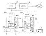
본 예의 추적가능성 관리시스템(S, 이하, 시스템(S)라고 한다)의 구성에 대해서 설명한다. 본 시스템(S)은 도 21에 나타낸 바와 같이 통신회선망(I)에 접속된 데이터제어장치(10)와 복수의 반송라인(81, 81a, 81b…)에서 행해지는 레이저·마킹의 순서(sequence)를 제어하는 순서단말(20)과, 반송라인(81)마다 배치된 제어단말(30, 30a, 30b…)과 각 제어단말(30)에 의해 제어되는 레이저마커(40, 40a, 40b…)와 레이저마커(40)에 의해 마킹된 2차원코드를 읽기 위한 리더(reader, 60, 60a, 60b…)를 구비하여 구성된다.The configuration of the traceability management system S (hereinafter, referred to as system S) of this example will be described. As shown in Fig. 21, the system S is a sequence of laser marking performed on the
전기기기(70)는 메인 반송라인(80) 위를 반송되어 오는 작업(work)에 대하여 반송라인(81, 81a, 81b…)에 의해 반송되어 온 부품(72)을 도시하지 않은 로봇암 (robot arm) 등에 의해 순차조합을 행하고, 검사를 행하는 것에 의해 제조된다.The
또한, 이하의 실시형태에는 복수의 부품에 의해 구성된 전기기기(70)를 제품의 예를 들어 설명하는데, 단일의 부품· 재료로 구성된 제품·부품에 본 발명을 적용하는 것 또한 물론 가능하다.In addition, although the
부품(72)은 반송라인(81)에 의해 순차반송된다. 그리고, 반송된 부품(72)에 2차원코드(1)를 마킹하기 위한 레이저마커(40)가 각 반송라인(81)에 배설된다. 그 레이저마커(40)는 제조이력정보에 접근하기 위한 식별번호를 포함하는 2차원코드(1)를 반송라인(81)에서 반송되어 온 부품(72)의 소정위치에 순차로 마킹한다.The
또한, 각 반송라인(81)에는 레이저마커(40)의 하류측에 리더(60)가 배설된다. 그 리더(60)는 제어단말(30)의 제어신호에 따라, 레이저마커(40)에 의해 마킹된 2차원코드(1)를 읽어내고, 읽어낸 2차원코드(1)를 제어단말(30)로 송신한다. 제어단말(30)에는, 리더(60)로부터 송신되어 온 2차원코드(1)가 레이저마커(40)로 마킹시킨 2차원코드(1)과 일치하는지 아닌지를 확인한다. 확인결과 일치하지 않았다고 판단된 경우, 그 2차원코드(1)가 마킹된 부품(72)은 도시하지 않은 로봇암에 의해 반송라인(81)에서 제거되도록 구성된다.In addition, the reader 60 is arranged in each conveying line 81 downstream of the
또한, 본 예의 순서단말(20)은 복수의 반송라인(81)에서 행해지는 레이저·마킹의 순서를 제어하는데, 그 기능을 데이터제어장치(10)가 행하도록 구성해도 좋다.In addition, the
본 예의 2차원코드(1)는 레이저마커(40)에 의한 도트마킹으로 형성되기 때문에 극소한 길이의 부품(72)에서 극대한 길이의 부품(72)에 대하여도 정밀도 있게 형성하는 것이 가능하다. 또한, 레이저·마킹방식이기 때문에 제품이나 부품에 직접마킹하는 것이 가능하다.Since the two-
종래의 방법으로는, 극소부품에 대하여 식별번호나 재료의 내용·제조조건에 관한 정보 등을 부여하는 것이 불가능했지만, 본 발명에 의하면 극소부품에 대해서도 식별번호를 포함한 2차원코드를 마킹하는 것이 가능하다. 따라서, 전기기기(70)를 구성하는 거의 모든 부품(72)의 추적가능성을 관리하는 것이 가능하다.In the conventional method, it is not possible to give an identification number, information on the contents, manufacturing conditions, etc. of a micro component, but according to the present invention, it is possible to mark a two-dimensional code including an identification number for a micro component. Do. Thus, it is possible to manage the traceability of almost all of the
또한, 본 발명에서는 부품(72)에 대하여 직접 레이저·마킹을 하기 때문에 인쇄된 2차원코드(1)를 부착하거나, 2차원코드(1)를 직접 인쇄하거나 하는 경우에 비하여, 몇 년이 지나 인쇄가 벗겨지거나, 인자부분이 흐릿해져 인식 불가능하게 되거나 하는 일이 없기 때문에 바람직하다. 또한, 레이저 빔에 의한 마킹이기 때문에 인쇄 등을 부착하는 경우와 같이 소모품이 없어서 바람직하다.Further, in the present invention, since the laser marking is performed on the
다음으로, 도 23에 근거하여 본 시스템에 의한 작업공정에 대하여 설명한다. 우선, 제조이력정보 취득공정에는, 통신회선망(I) 등에서 얻어진 부품(72)의 제조이력정보를 데이터베이스(16c)에 격납한다(단계 S21). 그리고 조작자는 각 반송라인(81)에 대하여, 반송된 부품(72)의 제조이력정보를 특정하기 위한 식별번호를 입력부(12)에 의해 지정한다(단계 S22). 반송된 부품(72)에 대응하는 제조이력정보의 특정은 배송번호 등에 의해 행해진다.Next, the operation process by this system is demonstrated based on FIG. First, in the manufacturing history information acquisition step, the manufacturing history information of the
2차원코드화공정에서 데이터제어장치(10)는, 각 반송라인(81)에 대해 지정된 식별번호를 교환하여 2차원코드(1)를 형성하고, 도 22(A)에 나타낸 바와 같이 2차원코드(1)의 명암무늬를 구성하는 검은셀(2a)과 흰셀(2b)의 단위셀을 각각 0, 1에 대응시켜 도 22(B)에 나타낸 바와 같이 1셀 1비트(bit)로 한 2차원배열 데이터(3)를 형성한다(단계 S23).In the two-dimensional coding process, the
다음으로, 파라미터 설정공정에서는 부품(72)의 마킹영역 사이즈를 고려하여 2차원코드(1)의 크기를 입력부(12)에 입력해서 설정하고, 2차원코드(1)의 크기에 근거하여 도 25에 나타낸 바와 같이 1셀의 크기와 가공하는 소재에 맞춘 빔스폿(beam spot)의 가공지름 및 1셀에 들어간 빔스폿의 수 등의 크기정보를 부가해, 레이저의 파워, Q스위치주파수, 도트조사시간, 회수, 레이저파장 등의 최적값을 파라미터정보(16d)에 근거하여 지정한다(S24).Next, in the parameter setting step, the size of the two-
결국, 마킹가공하는 소재에 의해 레이저의 반응값이 다르기 때문에 같은 직경에서 같은 출력의 빔스폿을 조사해도, 형성된 도트(5)의 직경이 다르기 때문에 가공된 소재의 종류와 형성된 도트(5)의 크기로부터 미리 빔스폿의 가공지름을 설정하고, 그것에 근거하여 1셀에 배치된 도트(5)의 종횡의 수(n, m) 및 도트(5) 사이의 거리 등이 설정된다. 즉, 후술하는 바와 같이 같은 데이터를 포함한 2차원코드(1)를 마킹하는 경우에, 부품(72)의 마킹영역의 크기에 맞추어 2차원코드(1)의 크기를 적절하게 설정하는 것이 가능하다.As a result, since the response value of the laser varies depending on the material to be processed, even if the beam spots of the same output are irradiated at the same diameter, the diameter of the formed
다음으로, 1셀 1비트화 한 2차원배열 데이터(3)에 상기 1셀의 크기정보를 조합하여 스캐닝(scanning)하는 순서로 빔스폿 좌표가 보존되어 있는 가공데이터로 변환한다. 여기까지의 공정을 데이터제어장치(10)에서 행하고, 변환된 가공데이터 및 제어신호는 순서단말(20)로 송신된다(단계 S25). 이때, 도트(5)를 빔조사에 의해 형성하는 각 좌표데이터가 특정된다.Next, the beam spot coordinates are converted into processed data in the order of scanning by combining the size information of the one cell with the two-
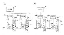
그리고, 마킹공정(단계 S26)에 있어서 순서단말(20)에서는 가공데이터의 가공순서를 배열한다. 결국, 가공데이터를 도 21에 나타낸 바와 같이 제어단말(30a, 30b…)에 병렬로 운송하고 동시에 마킹가공하든지, 또는 도 24에 나타낸 바와 같이 가공데이터의 운송을 직렬로 하여 가공을 대기하는 제어단말(30b…)로 순차적으로 보낼 것인가를 결정한다. 즉, 도 21에 나타낸 구성에서, 제어단말(30)은 순서단말(20)과 직접 접속되어 있고, 각 제어단말(30)은 병행하여 마킹제어를 행한다. 한편, 도 24에 나타낸 구성에서 제어단말(30)은 직렬로 접속되어 있고, 레이저마커(40)에 의한 레이저·마킹은 소정의 시간간격으로 행해진다.In the marking step (step S26), the
이처럼 제어단말(30a, 30b…)에 스캐닝하는 순서로 빔스폿 좌표가 보존되어 있는 데이터를 병렬로 운송하면, 각 레이저마커(40a, 40b…)로 레이저 빔이 소재의 표시면에 조사되어, 도 26(A)에 나타낸 바와 같이 도트(5)를 종횡으로 배치하여 검은셀(2a)이 형성되고, 레이저 빔이 조사되지 않은 부분은 흰셀(2b)로 되어 2차원코드(1)가 형성된다. 이 검은셀(2a)은 셀(2)의 크기가 규정되고, 셀(2)의 외곽을 따라 도트(5)가 배치되고, 그 안에 배치되는 수도 규정되어 있기 때문에, 정확한 검은셀(2a)을 구성하는 것이 가능하다.In this way, when data in which the beam spot coordinates are stored is transported in parallel in the order of scanning to the
이렇게 레이저마킹된 2차원코드(1)는 레이저마커(40)의 하류측에 배설된 리더(60)에 의해 읽히고, 읽혀진 2차원코드(1)는 제어단말(30)에 송신된다. 제어단말 (30)에서는 올바르게 마킹되었는지 아닌지가 확인된다. 즉, 제어단말(30)에서는 리더(60)에서 송신되어 온 2차원코드(1)가 레이저마커(40)로 마킹시킨 2차원코드(1)와 일치하는지 아닌지를 확인한다. 그리고, 일치한다고 판단된 경우, 그 부품(72)은 제조공정의 반송라인(80) 위의 작업에서 부착되고(S26), 일치하지 않는다고 판단된 경우에는 그 부품(72)은 도시하지 않은 로봇암 등에 의해 반송라인(81)에서 제거된다.The laser-marked two-
도 26(A)는 도트(5)를 4 × 4로 배열한 것을 1셀에 설정한 2차원코드(1)의 예이다. 이것에 대하여, 도 26(B)는 1셀 1도트로 설정하여 같은 2차원코드(1)를 형성한 예이다. 같은 도면(B)에는 같은 도면(A)과 같은 가공지름의 도트(5)가 사용된다. 즉, 같은 도면(B)의 2차원코드(1)의 종횡의 길이는, 같은 도면(A)의 2차원코드(1)의 종횡의 길이의 약 1/4배가 된다. 이처럼 같은 정보를 다른 사이즈의 2차원코드(1)에 나타내는 것이 가능하다.Fig. 26A is an example of the two-
또한, 빔스폿 좌표를 정확히 제어하는 것에 의해, 도트(5)의 배치 정밀도가 높은 2차원코드(1)를 마킹하는 것이 가능하기 때문에, 미세한 사이즈의 2차원코드(1)에 설정한 경우에 있어서도 높은 독해 정밀도를 확보하는 것이 가능하다.In addition, since it is possible to mark the two-
또한, 상기 실시형태에는 2차원코드화된 데이터를 부품(72)의 식별번호로 했지만, 이것에 한정되지 않고 극대(極大)한 부품 등 넓은 마킹영역을 확보하는 것이 가능한 것에 대해서는, 제조이력정보 그 자체를 2차원코드화하여 마킹해도 좋다. 그렇게 하면, 불량부품을 특정하고 그 부품에 부여된 2차원코드(1)를 읽어내는 것에 의해 직접제조이력정보를 아는 것이 가능하고, 품질에 관한 문의나 클레임 등에 신속하게 대응하는 것이 가능하게 된다. 또한, 전기기기(70)를 구성하는 거의 모든 부품(72)에 대하여 2차원코드(1)를 레이저·마킹해도 좋고, 중요한 부품에만 2차원코드(1)를 레이저·마킹해도 좋다.In the above embodiment, although the two-dimensional coded data is used as the identification number of the
이상과 같이, 전기기기(70)의 구성부품(72)에는 식별번호를 나타내는 2차원코드(1)를 직접 레이저·마킹하기 때문에 전기기기(70)에 이상이 발생한 경우에, 이상의 원인이되는 부품(72)을 특정하면, 그 부품(72)에 부여된 2차원코드(1)로부터 데이터(16c)에 기억된 제조이력정보로 바로 그리고 확실하게 접근하는 것이 가능하다.As described above, since the two-
이것에 의해, 이상의 원인이 되는 부품(72)의 제조일시, 제조라인번호, 품번, 제조담당자번호, 부품사용로트번호, 검사판정결과, 출하트레이번호 등을 아는 것이 가능하고, 그 부품(72)의 생성, 유통경력, 제조공정 등을 신속하게 추적조사하는 것이 가능하게 된다. 그리고 고장부분의 발생원인을 정확히 알아내고, 다음번 제품공정에 있어서, 상기의 제조장치 등의 이상을 조정, 수리, 개선을 도모하고, 불량품을 일소(一掃)하는 것이 가능하여 전기기기(70)의 제조비용을 전체적으로 저감하는 것이 가능하게 된다. 또한 클레임비용, 고객대응 서비스비용의 저감이 가능하게 된다.As a result, it is possible to know the manufacturing date and time, the manufacturing line number, the part number, the manufacturing person number, the part use lot number, the inspection judgment result, the shipping tray number, and the like of the
또한, 미세한 2차원코드(1)를 레이저·마킹에 의해 부품(72)에 부여하는 것이 가능하기 때문에, 극소한 사이즈의 부품(72)에서 극대한 사이즈의 부품(72)에 이르기까지 거의 모든 부품(72)에 대하여 2차원코드(1)를 마킹하는 것이 가능하다.이것에 의해, 종래에는 신속한 추적조사가 어려웠던 극소한 사이즈의 부품(72)에 대해서도 제조이력정보를 바로 취득하는 것이 가능하다.In addition, since the fine two-
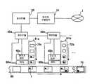
또한, 상기 실시형태에는 메인의 반송라인(80)으로 부품(72)을 공급하는 각반속라인(81)에 레이저마커(40) 및 리더(60)를 배설하고 있는데, 이것에 한정하지 않고, 도 27에 나타낸 바와 같이 마킹전용의 반송라인(82)에 레이저마커(40) 및 리더(60)를 배설하는 구성도 좋다.In addition, although the
이 경우, 부품메이커(B)에서 배송된 부품(72)은 반송라인(82)에 설치되고, 데이터제어장치(10)에서 순서단말(20)을 통해 송신된 2차원코드(1)를 레이저마커(40)에 의해 마킹된다. 그리고, 레이저·마킹된 2차원코드(1)는 리더(60)로 읽혀지고, 제어단말(30)에서 올바르게 마킹되었는지 아닌지가 판단된다. 또한, 순서단말(20)과 각 제어단말(30)의 접속은, 같은 도면(A)에 나타낸 바와 같이 병렬로 접속하여도 좋고, 같은 도면(B)에 나타낸 바와 같이 직렬로 접속해도 좋다.In this case, the
이상과 같이 본 발명에 의하면, 간단한 장치구성에 의해, 코드에 기입한 문자나 화상 등의 정보량의 많고 적음에 관계없이 지정된 코드사이즈로 2차원코드를 형성하는 것이 가능하다. 따라서 피마킹물에 따라 적절한 크기의 2차원코드를 부여하는 것이 가능하다.As described above, according to the present invention, it is possible to form a two-dimensional code with a designated code size regardless of the large or small amount of information such as characters or images written in the code. Therefore, it is possible to give a two-dimensional code of appropriate size according to the marked object.
또한, 셀 사이즈가 변경된 경우는, 같은 크기의 2차원코드에 다른 양의 정보를 격납하는 것이 가능하기 때문에, 마킹부분의 면적에 제한되지 않고, 원하는 정보를 2차원코드로 부여하는 것이 가능하다.In addition, when the cell size is changed, it is possible to store different amounts of information in two-dimensional code of the same size, so that the desired information can be given in two-dimensional code without being limited to the area of the marking portion.
더욱이, 코드사이즈와 셀수가 지정된 경우는, 정보량의 대소에 관계없이 지 정된 코드사이즈 및 셀사이즈의 2차원코드가 형성되고, 독해 정밀도를 향상시키는 것이 가능하다.Furthermore, when the code size and the number of cells are designated, two-dimensional codes of the specified code size and cell size are formed regardless of the magnitude of the information amount, and it is possible to improve the reading accuracy.
본 발명에 의하면, 레이저·마킹이 도트로 되기 때문에 마킹부분이 좌우로 튀어나가거나 공백부분이 생기거나 하는 등의 마킹오류가 방지되어, 고품질의 2차원코드를 작성하는 것이 가능하다. 또한 레이저·마킹이 도트로 되기 때문에 예를 들면, 1셀 1도트로 하면, 초미세한 2차원코드를 작성하는 것이 가능하고, 극소한 전자부품 등에도 2차원코드를 부여하는 것이 가능하다.According to the present invention, since the laser marking becomes a dot, a marking error such that the marking portion protrudes from side to side or a blank portion is prevented, and high quality two-dimensional code can be produced. In addition, since the laser marking becomes a dot, for example, if one cell is one dot, it is possible to create an ultra-fine two-dimensional code, and to give a two-dimensional code to an extremely small electronic component or the like.
더욱이, 레이저·마킹이 도트로 되기 때문에, 스텝사이즈 또는 도트개수를 지정하는 것에 의해 원하는 농도의 2차원코드를 작성하는 것이 가능하다. 또한, 레이저·마킹이 도트로 되기 때문에, 피마킹재에 연속적으로 레이저·마킹이 되는 벡터마킹에 비하여 소재에 주는 영향을 적게 하는 것이 가능하고, 대기후성(對候性), 내식성(耐蝕性), 대충격성(對衝擊性)에 뛰어난 마킹을 완성하는 것이 가능하다.Furthermore, since laser marking becomes a dot, it is possible to create a two-dimensional code having a desired density by specifying a step size or the number of dots. In addition, since the laser marking becomes a dot, it is possible to reduce the influence on the material as compared with the vector marking which is continuously laser-marked on the marked material, and the atmospheric and corrosion resistance It is possible to complete the marking with excellent impact resistance.
또한, 본 발명에서는 제품을 구성하는 개개의 부품에 대하여 제조이력정보로 접근하는 것이 가능한 식별번호를 포함하는 2차원코드, 또는 재료나 제조조건, 완성품질 등의 대량의 정보(제조이력정보)를 포함하는 2차원코드가 직접 레이저·마킹된다. 개개의 부품은 각각 크기나 마킹가능한 영역이 다르기 때문에, 그에 따라 2차원코드의 크기가 설정된다. 이것에 의해 극소한 사이즈를 갖는 부품에서 극대한 사이즈를 갖는 부품까지 거의 모든 부품에 대하여 2차원코드를 레이저·마킹하는 것이 가능하다.In addition, in the present invention, a two-dimensional code including an identification number that allows access to the manufacturing history information for each component constituting the product, or a large amount of information (manufacturing history information) such as materials, manufacturing conditions, and finished quality, etc. The two-dimensional code included is directly laser-marked. Since individual parts differ in size or markable area, the size of the two-dimensional code is set accordingly. As a result, it is possible to laser-mark two-dimensional codes for almost all parts, from parts having a very small size to parts having a very large size.
따라서, 제품의 이상이 부품에 기인한 경우에는, 부품에 부여된 2차원코드를 읽어내는 것에 의해, 바로 그 제품의 제조이력정보로 접근하는 것이 가능하다. 이러한 이유로 제조이력정보로 접근하기 위한 추적시간이 대폭으로 단축되고, 또한 확실하게 제조이력정보로 접근하는 것이 가능하다. 그리고, 이렇게 얻어진 부품의 제조이력정보를 제품의 제조공정에 반영시키는 것에 의해 불량품의 제조를 효과적으로 방지하는 것이 가능하다. 또한 재료나 제조조건, 완성품질 등의 대량의 정보를 포함한 2차원코드를 마킹하는 경우에는 별도로 기억된 제조이력정보에 접근하지 않고, 직접 그 2차원코드를 읽어내는 것에 의해 제조이력정보를 아는 것이 가능하고, 품질에 관한 문의나 클레임 등에 신속하게 대응하는 것이 가능하다.Therefore, when the abnormality of the product is caused by the part, it is possible to access the manufacturing history information of the product by reading the two-dimensional code applied to the part. For this reason, the tracking time for accessing the manufacturing history information is greatly shortened, and it is possible to reliably access the manufacturing history information. In addition, it is possible to effectively prevent the manufacture of defective products by reflecting the manufacturing history information of the parts thus obtained in the manufacturing process of the product. In addition, when marking two-dimensional codes containing a large amount of information such as materials, manufacturing conditions, and finished quality, it is necessary to know the manufacturing history information by directly reading the two-dimensional codes without accessing the separately stored manufacturing history information. It is possible to respond quickly to inquiries and claims about quality.
Claims (13)
Translated fromKoreanApplications Claiming Priority (4)
| Application Number | Priority Date | Filing Date | Title |
|---|---|---|---|
| JPJP-P-2003-00291400 | 2003-08-11 | ||
| JP2003291400AJP4433374B2 (en) | 2003-08-11 | 2003-08-11 | Traceability management method and management apparatus |
| JP2003292391AJP4454264B2 (en) | 2003-08-12 | 2003-08-12 | Two-dimensional code forming method and two-dimensional code forming apparatus |
| JPJP-P-2003-00292391 | 2003-08-12 |
Publications (2)
| Publication Number | Publication Date |
|---|---|
| KR20060038463A KR20060038463A (en) | 2006-05-03 |
| KR101019762B1true KR101019762B1 (en) | 2011-03-04 |
Family
ID=34137951
Family Applications (1)
| Application Number | Title | Priority Date | Filing Date |
|---|---|---|---|
| KR1020067001771AExpired - Fee RelatedKR101019762B1 (en) | 2003-08-11 | 2006-01-25 | Forming method and apparatus for forming two-dimensional code |
Country Status (5)
| Country | Link |
|---|---|
| US (1) | US7594613B2 (en) |
| EP (2) | EP2386979B1 (en) |
| KR (1) | KR101019762B1 (en) |
| AT (1) | ATE529818T1 (en) |
| WO (1) | WO2005015478A1 (en) |
Families Citing this family (26)
| Publication number | Priority date | Publication date | Assignee | Title |
|---|---|---|---|---|
| JP4570389B2 (en)* | 2004-04-26 | 2010-10-27 | アライ株式会社 | Method for forming two-dimensional code by laser marking and laser marking apparatus |
| US20070289956A1 (en)* | 2006-06-19 | 2007-12-20 | Andriy Knysh | Laser marking device and method |
| US8387983B2 (en)* | 2007-11-27 | 2013-03-05 | Angel Playing Cards Co., Ltd. | Shuffled playing cards and manufacturing method thereof |
| US8919777B2 (en) | 2007-11-27 | 2014-12-30 | Angel Playing Cards Co., Ltd. | Shuffled playing cards and manufacturing method thereof |
| US8552336B2 (en)* | 2008-12-23 | 2013-10-08 | Triune Ip Llc | Micro matrix data marking |
| JP5720155B2 (en)* | 2009-10-19 | 2015-05-20 | 株式会社リコー | Drawing control method, laser irradiation apparatus, drawing control program, and recording medium recording the same |
| US10543704B2 (en)* | 2012-11-01 | 2020-01-28 | Owens-Brockway Glass Container Inc. | Particle-coded container |
| GB201221184D0 (en)* | 2012-11-24 | 2013-01-09 | Spi Lasers Uk Ltd | Method for laser marking a metal surface with a desired colour |
| KR101976854B1 (en)* | 2013-03-04 | 2019-05-09 | 현대자동차주식회사 | System for recognizing information of vehicle using the QR code and method thereof |
| JP2015005835A (en)* | 2013-06-19 | 2015-01-08 | シャープ株式会社 | Image processing device, image forming device, and recording medium |
| JP2015087998A (en)* | 2013-10-31 | 2015-05-07 | セイコーエプソン株式会社 | Printing control apparatus, program, printing method, |
| CN103794135B (en)* | 2014-02-17 | 2016-01-20 | 立德高科(北京)数码科技有限责任公司 | Carry out generating to the mark formed by dot matrix and Quick Response Code and know method for distinguishing |
| US9594937B2 (en) | 2014-02-28 | 2017-03-14 | Electro Scientific Industries, Inc. | Optical mark reader |
| US9269035B2 (en) | 2014-02-28 | 2016-02-23 | Electro Scientific Industries, Inc. | Modified two-dimensional codes, and laser systems and methods for producing such codes |
| US10921788B2 (en)* | 2015-07-24 | 2021-02-16 | Schemaport, Llc | Route based manufacturing system analysis, apparatuses, systems, and methods |
| CN105160854B (en) | 2015-09-16 | 2019-01-11 | 小米科技有限责任公司 | Apparatus control method, device and terminal device |
| JP6843686B2 (en) | 2017-04-14 | 2021-03-17 | 株式会社三井ハイテック | Manufacturing method of metal products and metal products |
| CN107133809A (en)* | 2017-06-28 | 2017-09-05 | 山西讯龙科技有限公司 | The Quick Response Code quality tracing system and method and two-dimensional code printing apparatus of Internet of Things |
| CN111328413A (en) | 2017-09-11 | 2020-06-23 | 特瑞堡密封系统美国有限公司 | Sealing detection system and method |
| US11660899B2 (en)* | 2017-11-07 | 2023-05-30 | Sumitomo Electric Sintered Alloy. Ltd. | Iron-based sintered body, method for laser-marking the same, and method for manufacturing the same |
| IT201800003770A1 (en)* | 2018-03-20 | 2019-09-20 | Mecc Pi Erre S R L Di Pederzoli Ruggero & C | PLANT FOR THE EXECUTION OF OPERATIONS FOR THE REALIZATION OF A PIECE STARTING FROM A CAST |
| US11738409B2 (en) | 2018-05-25 | 2023-08-29 | Laserax Inc. | Metal workpieces with shot blast resistant identifiers, methods and systems for laser-marking such identifiers |
| CN109948389A (en)* | 2019-03-28 | 2019-06-28 | 尤尼泰克(嘉兴)信息技术有限公司 | A kind of drafting of extension two dimensional code and recognition methods accommodating large capacity |
| CN110059783A (en)* | 2019-04-30 | 2019-07-26 | 蒙娜丽莎集团股份有限公司 | Ceramic Tiles laser bar code management system |
| FR3146528A1 (en) | 2023-03-10 | 2024-09-13 | Saint-Gobain Glass France | Device for reading a matrix code on a sheet of glass |
| EP4435376A1 (en) | 2023-03-23 | 2024-09-25 | Saint-Gobain Glass France | Method and system for measuring the position of a data matrix code from the reference edges of a rectangular glass sheet |
Citations (2)
| Publication number | Priority date | Publication date | Assignee | Title |
|---|---|---|---|---|
| JP2000222516A (en)* | 1999-01-28 | 2000-08-11 | Kazuo Sato | Method for forming two-dimensional code |
| JP2003140726A (en)* | 2001-10-30 | 2003-05-16 | Denso Corp | Manufacture history information recording device for product and manufacture history information recording device for parts |
Family Cites Families (15)
| Publication number | Priority date | Publication date | Assignee | Title |
|---|---|---|---|---|
| JPS62212176A (en)* | 1986-03-14 | 1987-09-18 | Nec Corp | Bar code printing system |
| JPH04284272A (en)* | 1991-03-14 | 1992-10-08 | Mitsubishi Electric Corp | print control device |
| AU661205B2 (en)* | 1992-11-25 | 1995-07-13 | Eastman Kodak Company | Multi-user digital laser imaging system |
| US6000614A (en)* | 1996-12-20 | 1999-12-14 | Denso Corporation | Two-dimensional code reading apparatus |
| US5922593A (en)* | 1997-05-23 | 1999-07-13 | Becton, Dickinson And Company | Microbiological test panel and method therefor |
| JP3557512B2 (en) | 1997-12-03 | 2004-08-25 | ミヤチテクノス株式会社 | Laser marking method for 2D barcode |
| JP2913475B1 (en)* | 1998-02-17 | 1999-06-28 | 一男 佐藤 | 2D code formation method |
| JP3716615B2 (en)* | 1998-04-22 | 2005-11-16 | 株式会社デンソー | Two-dimensional code printing data creation device and recording medium |
| CN100458763C (en)* | 1999-12-28 | 2009-02-04 | 松下电器产业株式会社 | Information storage medium, non-contact IC tag, access device, access system, life cycle management system, input/output method, and access method |
| US6533181B1 (en)* | 2000-07-22 | 2003-03-18 | Roboric Vision Systems, Inc. | Direct marking of parts with encoded symbology method, apparatus and symbolody |
| JP3927388B2 (en)* | 2000-09-27 | 2007-06-06 | 株式会社リコー | Image processing apparatus, image processing method, and recording medium |
| EP1316924A1 (en)* | 2001-11-28 | 2003-06-04 | Agfa-Gevaert | Security marking method and items provided with security marks |
| JP4076343B2 (en)* | 2001-12-05 | 2008-04-16 | 株式会社小松製作所 | Positioning method and positioning apparatus for dot mark forming position of semiconductor wafer |
| ATE377776T1 (en)* | 2002-04-15 | 2007-11-15 | Fujifilm Corp | LASER MARKING ON LIGHT SENSITIVE MATERIAL AND LIGHT SENSITIVE MATERIAL INCLUDING SAID MARKING |
| JP3923866B2 (en)* | 2002-07-19 | 2007-06-06 | 株式会社キーエンス | Two-dimensional code reading device setting method, two-dimensional code reading setting device, two-dimensional code reading device setting program, and computer-readable recording medium |
- 2004
- 2004-08-11USUS10/565,775patent/US7594613B2/ennot_activeExpired - Fee Related
- 2004-08-11WOPCT/JP2004/011799patent/WO2005015478A1/enactiveApplication Filing
- 2004-08-11EPEP11006167.8Apatent/EP2386979B1/ennot_activeExpired - Lifetime
- 2004-08-11ATAT04771760Tpatent/ATE529818T1/ennot_activeIP Right Cessation
- 2004-08-11EPEP04771760Apatent/EP1655683B1/ennot_activeExpired - Lifetime
- 2006
- 2006-01-25KRKR1020067001771Apatent/KR101019762B1/ennot_activeExpired - Fee Related
Patent Citations (2)
| Publication number | Priority date | Publication date | Assignee | Title |
|---|---|---|---|---|
| JP2000222516A (en)* | 1999-01-28 | 2000-08-11 | Kazuo Sato | Method for forming two-dimensional code |
| JP2003140726A (en)* | 2001-10-30 | 2003-05-16 | Denso Corp | Manufacture history information recording device for product and manufacture history information recording device for parts |
Also Published As
| Publication number | Publication date |
|---|---|
| US7594613B2 (en) | 2009-09-29 |
| EP2386979B1 (en) | 2014-10-08 |
| ATE529818T1 (en) | 2011-11-15 |
| KR20060038463A (en) | 2006-05-03 |
| EP1655683A4 (en) | 2009-06-10 |
| EP2386979A1 (en) | 2011-11-16 |
| WO2005015478A1 (en) | 2005-02-17 |
| EP1655683A1 (en) | 2006-05-10 |
| US20070038464A1 (en) | 2007-02-15 |
| EP1655683B1 (en) | 2011-10-19 |
Similar Documents
| Publication | Publication Date | Title |
|---|---|---|
| KR101019762B1 (en) | Forming method and apparatus for forming two-dimensional code | |
| CN100378740C (en) | Method and device for forming two-dimensional bar code | |
| US11878540B2 (en) | Flexographic printing plate with persistent markings | |
| CN104249217A (en) | Apparatusand method for accurate structure marking and marking-assisted structure locating | |
| US20140263674A1 (en) | Systems, Methods, and Apparatus for Integrating Scannable Codes in Medical Devices | |
| US20200016916A1 (en) | System and process for persistent marking of flexo plates and plates marked therewith | |
| CN113330368B (en) | System and method for durable marking of flexographic plates and plates marked therewith | |
| CN114730141B (en) | System and method for permanent marking of flexographic plates and plates marked therewith | |
| CN113348088B (en) | Printing system, printing device, printing method, and storage medium | |
| JPH11232369A (en) | Two-dimensional code forming method | |
| MY122961A (en) | Chip scale marker and marking method | |
| KR101079606B1 (en) | Apparatus and method for stamping a JR code on jewelry using a laser beam | |
| JP2004259004A (en) | Data processing device using three-dimensional code, data processing method using three-dimensional code, data processing program using three-dimensional code, article, tag, and package having three-dimensional code | |
| JP2005063094A (en) | Traceability management method and management apparatus | |
| JP4454264B2 (en) | Two-dimensional code forming method and two-dimensional code forming apparatus | |
| JP4540397B2 (en) | Two-dimensional code, two-dimensional code forming apparatus and forming method, and two-dimensional code reading apparatus and reading method | |
| JP4394469B2 (en) | ROOF MATERIAL, LASER MARKING METHOD, AND LASER MARKING DEVICE | |
| WO2023281923A1 (en) | Printed image inspection device and printed image inspection method | |
| JP2005165660A (en) | Building information management method and device | |
| Canu et al. | Die-Level Serialization Platform Demonstration | |
| Jong | Developing guidelines for embedding codes onto products produced using Selective Laser Sintering | |
| JP7248170B2 (en) | Printing system, printing device, printing method and program | |
| KR102770645B1 (en) | Laser machining system for manufacturing display device using carrier glass | |
| Uyan et al. | Additively Manufactured Tags for Cast Part Traceability Using Two-Dimensional Digital Code Direct-Part-Marking | |
| WO2023195507A1 (en) | Printing system |
Legal Events
| Date | Code | Title | Description |
|---|---|---|---|
| PA0105 | International application | St.27 status event code:A-0-1-A10-A15-nap-PA0105 | |
| P11-X000 | Amendment of application requested | St.27 status event code:A-2-2-P10-P11-nap-X000 | |
| P13-X000 | Application amended | St.27 status event code:A-2-2-P10-P13-nap-X000 | |
| PG1501 | Laying open of application | St.27 status event code:A-1-1-Q10-Q12-nap-PG1501 | |
| N231 | Notification of change of applicant | ||
| PN2301 | Change of applicant | St.27 status event code:A-3-3-R10-R13-asn-PN2301 St.27 status event code:A-3-3-R10-R11-asn-PN2301 | |
| A201 | Request for examination | ||
| PA0201 | Request for examination | St.27 status event code:A-1-2-D10-D11-exm-PA0201 | |
| E902 | Notification of reason for refusal | ||
| PE0902 | Notice of grounds for rejection | St.27 status event code:A-1-2-D10-D21-exm-PE0902 | |
| E13-X000 | Pre-grant limitation requested | St.27 status event code:A-2-3-E10-E13-lim-X000 | |
| P11-X000 | Amendment of application requested | St.27 status event code:A-2-2-P10-P11-nap-X000 | |
| P13-X000 | Application amended | St.27 status event code:A-2-2-P10-P13-nap-X000 | |
| E701 | Decision to grant or registration of patent right | ||
| PE0701 | Decision of registration | St.27 status event code:A-1-2-D10-D22-exm-PE0701 | |
| GRNT | Written decision to grant | ||
| PR0701 | Registration of establishment | St.27 status event code:A-2-4-F10-F11-exm-PR0701 | |
| PR1002 | Payment of registration fee | St.27 status event code:A-2-2-U10-U12-oth-PR1002 Fee payment year number:1 | |
| PG1601 | Publication of registration | St.27 status event code:A-4-4-Q10-Q13-nap-PG1601 | |
| FPAY | Annual fee payment | Payment date:20140127 Year of fee payment:4 | |
| PR1001 | Payment of annual fee | St.27 status event code:A-4-4-U10-U11-oth-PR1001 Fee payment year number:4 | |
| FPAY | Annual fee payment | Payment date:20141212 Year of fee payment:5 | |
| PR1001 | Payment of annual fee | St.27 status event code:A-4-4-U10-U11-oth-PR1001 Fee payment year number:5 | |
| LAPS | Lapse due to unpaid annual fee | ||
| PC1903 | Unpaid annual fee | St.27 status event code:A-4-4-U10-U13-oth-PC1903 Not in force date:20160226 Payment event data comment text:Termination Category : DEFAULT_OF_REGISTRATION_FEE | |
| PC1903 | Unpaid annual fee | St.27 status event code:N-4-6-H10-H13-oth-PC1903 Ip right cessation event data comment text:Termination Category : DEFAULT_OF_REGISTRATION_FEE Not in force date:20160226 |