KR101018626B1 - Ultrasonic Probe with Heat Sink - Google Patents
Ultrasonic Probe with Heat SinkDownload PDFInfo
- Publication number
- KR101018626B1 KR101018626B1KR1020080071290AKR20080071290AKR101018626B1KR 101018626 B1KR101018626 B1KR 101018626B1KR 1020080071290 AKR1020080071290 AKR 1020080071290AKR 20080071290 AKR20080071290 AKR 20080071290AKR 101018626 B1KR101018626 B1KR 101018626B1
- Authority
- KR
- South Korea
- Prior art keywords
- heat sink
- ultrasonic probe
- heat
- layer
- ultrasonic
- Prior art date
- Legal status (The legal status is an assumption and is not a legal conclusion. Google has not performed a legal analysis and makes no representation as to the accuracy of the status listed.)
- Active
Links
- 239000000523sampleSubstances0.000titleclaimsabstractdescription96
- 238000003780insertionMethods0.000claimsdescription15
- 230000037431insertionEffects0.000claimsdescription15
- 238000000034methodMethods0.000claimsdescription6
- 230000017525heat dissipationEffects0.000claimsdescription3
- 230000001154acute effectEffects0.000claimsdescription2
- 230000015556catabolic processEffects0.000abstractdescription23
- 238000006731degradation reactionMethods0.000abstractdescription23
- 239000000463materialSubstances0.000abstractdescription8
- 230000006866deteriorationEffects0.000abstractdescription7
- 230000020169heat generationEffects0.000abstractdescription5
- 238000002604ultrasonographyMethods0.000description11
- 238000003384imaging methodMethods0.000description3
- 230000005540biological transmissionEffects0.000description2
- 239000010949copperSubstances0.000description2
- 230000008878couplingEffects0.000description2
- 238000010168coupling processMethods0.000description2
- 238000005859coupling reactionMethods0.000description2
- 238000009792diffusion processMethods0.000description2
- 230000005855radiationEffects0.000description2
- 230000001225therapeutic effectEffects0.000description2
- 230000003313weakening effectEffects0.000description2
- RYGMFSIKBFXOCR-UHFFFAOYSA-NCopperChemical compound[Cu]RYGMFSIKBFXOCR-UHFFFAOYSA-N0.000description1
- 206010028980NeoplasmDiseases0.000description1
- 230000002411adverseEffects0.000description1
- 229910052782aluminiumInorganic materials0.000description1
- XAGFODPZIPBFFR-UHFFFAOYSA-NaluminiumChemical compound[Al]XAGFODPZIPBFFR-UHFFFAOYSA-N0.000description1
- 201000011510cancerDiseases0.000description1
- 238000006243chemical reactionMethods0.000description1
- 229910052802copperInorganic materials0.000description1
- 238000003745diagnosisMethods0.000description1
- 230000000694effectsEffects0.000description1
- 238000010438heat treatmentMethods0.000description1
- 208000021760high feverDiseases0.000description1
- 230000004130lipolysisEffects0.000description1
- 229910052751metalInorganic materials0.000description1
- 239000002184metalSubstances0.000description1
- 238000012986modificationMethods0.000description1
- 230000004048modificationEffects0.000description1
- 238000000465mouldingMethods0.000description1
- 230000000452restraining effectEffects0.000description1
- SBEQWOXEGHQIMW-UHFFFAOYSA-NsiliconChemical compound[Si].[Si]SBEQWOXEGHQIMW-UHFFFAOYSA-N0.000description1
- 229910052710siliconInorganic materials0.000description1
- 239000010703siliconSubstances0.000description1
- 238000009210therapy by ultrasoundMethods0.000description1
- 238000012285ultrasound imagingMethods0.000description1
Images


Classifications
- A—HUMAN NECESSITIES
- A61—MEDICAL OR VETERINARY SCIENCE; HYGIENE
- A61B—DIAGNOSIS; SURGERY; IDENTIFICATION
- A61B8/00—Diagnosis using ultrasonic, sonic or infrasonic waves
- G—PHYSICS
- G01—MEASURING; TESTING
- G01N—INVESTIGATING OR ANALYSING MATERIALS BY DETERMINING THEIR CHEMICAL OR PHYSICAL PROPERTIES
- G01N29/00—Investigating or analysing materials by the use of ultrasonic, sonic or infrasonic waves; Visualisation of the interior of objects by transmitting ultrasonic or sonic waves through the object
- G01N29/22—Details, e.g. general constructional or apparatus details
- G01N29/24—Probes
- A—HUMAN NECESSITIES
- A61—MEDICAL OR VETERINARY SCIENCE; HYGIENE
- A61B—DIAGNOSIS; SURGERY; IDENTIFICATION
- A61B8/00—Diagnosis using ultrasonic, sonic or infrasonic waves
- A61B8/44—Constructional features of the ultrasonic, sonic or infrasonic diagnostic device
- A61B8/4483—Constructional features of the ultrasonic, sonic or infrasonic diagnostic device characterised by features of the ultrasound transducer
- A—HUMAN NECESSITIES
- A61—MEDICAL OR VETERINARY SCIENCE; HYGIENE
- A61B—DIAGNOSIS; SURGERY; IDENTIFICATION
- A61B8/00—Diagnosis using ultrasonic, sonic or infrasonic waves
- A61B8/54—Control of the diagnostic device
- A61B8/546—Control of the diagnostic device involving monitoring or regulation of device temperature
- G—PHYSICS
- G01—MEASURING; TESTING
- G01N—INVESTIGATING OR ANALYSING MATERIALS BY DETERMINING THEIR CHEMICAL OR PHYSICAL PROPERTIES
- G01N29/00—Investigating or analysing materials by the use of ultrasonic, sonic or infrasonic waves; Visualisation of the interior of objects by transmitting ultrasonic or sonic waves through the object
- G—PHYSICS
- G10—MUSICAL INSTRUMENTS; ACOUSTICS
- G10K—SOUND-PRODUCING DEVICES; METHODS OR DEVICES FOR PROTECTING AGAINST, OR FOR DAMPING, NOISE OR OTHER ACOUSTIC WAVES IN GENERAL; ACOUSTICS NOT OTHERWISE PROVIDED FOR
- G10K11/00—Methods or devices for transmitting, conducting or directing sound in general; Methods or devices for protecting against, or for damping, noise or other acoustic waves in general
- G10K11/004—Mounting transducers, e.g. provided with mechanical moving or orienting device
Landscapes
- Health & Medical Sciences (AREA)
- Life Sciences & Earth Sciences (AREA)
- Physics & Mathematics (AREA)
- General Health & Medical Sciences (AREA)
- Engineering & Computer Science (AREA)
- Pathology (AREA)
- Nuclear Medicine, Radiotherapy & Molecular Imaging (AREA)
- Veterinary Medicine (AREA)
- Public Health (AREA)
- Animal Behavior & Ethology (AREA)
- Surgery (AREA)
- Biophysics (AREA)
- Molecular Biology (AREA)
- Radiology & Medical Imaging (AREA)
- Medical Informatics (AREA)
- Biomedical Technology (AREA)
- Heart & Thoracic Surgery (AREA)
- Chemical & Material Sciences (AREA)
- Analytical Chemistry (AREA)
- Gynecology & Obstetrics (AREA)
- Biochemistry (AREA)
- Immunology (AREA)
- General Physics & Mathematics (AREA)
- Acoustics & Sound (AREA)
- Multimedia (AREA)
- Ultra Sonic Daignosis Equipment (AREA)
- Transducers For Ultrasonic Waves (AREA)
Abstract
Translated fromKoreanDescription
Translated fromKorean본 발명은 압전체의 특성 저하를 억제하여 초음파 프로브의 성능 저하 및 내구성 약화를 방지하고, 음향렌즈의 발열을 방지함으로써 환자와의 접촉면 온도를 낮추도록 하는 히트 싱크를 가지는 초음파 프로브에 관한 것이다.The present invention relates to an ultrasonic probe having a heat sink to reduce the temperature of the contact surface with a patient by suppressing the degradation of the piezoelectric property to prevent degradation of performance and deterioration of durability of the ultrasonic probe and to prevent heat generation of the acoustic lens.
일반적으로, 초음파 영상장치는 크게 전기 및 초음파 신호의 변환을 담당하는 초음파 프로브, 송.수신되는 신호를 처리하는 신호처리부, 그리고 초음파 프로브와 신호처리부에서 얻은 신호를 이용하여 영상을 표시하는 디스플레이부로 이루어진다.In general, an ultrasound imaging apparatus generally includes an ultrasonic probe that is responsible for converting electrical and ultrasonic signals, a signal processor that processes transmitted and received signals, and a display unit that displays an image using signals obtained from the ultrasonic probe and the signal processor. .
이중에서 초음파 프로브는 신호를 변환시키는 역할을 하는 부분으로서, 초음파 영상의 질을 좌우하는 중요한 부분이다. 즉, 초음파 프로브는 전기 에너지와 음향 에너지를 상호 변환시키는 작용을 한다. 이러한 초음파 프로브가 갖추어야 할 기본 조건으로서, 전기-음향 변환효율(전기기계 결합계수), 초음파 펄스(pulse) 특성, 및 초음파 빔(beam)의 초점 특성 또는 집속성이 좋아야 한다.Among them, the ultrasonic probe converts a signal and is an important part that determines the quality of an ultrasound image. That is, the ultrasonic probe functions to convert electrical energy and acoustic energy into mutual. As a basic condition to be equipped with such an ultrasonic probe, the electro-acoustic conversion efficiency (electromechanical coupling coefficient), the ultrasonic pulse pulse characteristics, and the focus characteristic or focusing property of the ultrasonic beam should be good.
종래의 의료용으로 사용되는 초음파 프로브를 첨부된 도면을 참조하여 설명 하면 다음과 같다.Referring to the accompanying drawings, a conventional ultrasonic probe for medical purposes is as follows.
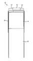
도 1은 종래의 기술에 따른 의료용 초음파 프로브를 도시한 단면도이다. 도시된 바와 같이, 종래의 기술에 따른 의료용 초음파 프로브(10)는, 환자와 접촉하는 전면부부터 음향렌즈(Acoustic lens; 11), 정합층(12), 압전체(13) 및 후면층(14)이 배열된다.1 is a cross-sectional view showing a medical ultrasound probe according to the prior art. As shown, the
음향렌즈(11)는 정합층(12)의 전면에 덮여지도록 형성되어 초음파를 집속한다.The
정합층(12)은 압전체(13)의 초음파 송/수신면의 전극상에 형성되어 초음파의 반사율과 효율을 증가시킨다.The matching layer 12 is formed on the electrode of the ultrasonic transmission / reception surface of the
압전체(13)는 후면층(14)의 전면에 접합되고, FPCB(Flexible Printed Circuit Board; 15)에 의해 메인 PCB에 연결되며, 전기적 신호를 음향신호인 초음파로 변환시켜 공기중으로 내보내고, 공기중에서 반사되어 돌아오는 초음파 반사신호를 다시 전기적 신호로 변환시켜서 장치로 보낸다.The
후면층(14)은 케이스(16)에 위치한 상태에서 실리콘(Silicon)의 메움에 의해 고정되며, 후방으로 방출되는 불필요한 초음파를 흡수한다.The
이와 같은, 종래의 의료용 초음파 프로브(10)는 용도에 따라 크게 두 가지로 나뉘는데, 첫째는 영상진단기에 사용되는 이미지용 프로브이고, 둘째는 암치료, 지방 분해 등의 HiFU(High Intensity Focused Ultrasound) 치료용 시스템에 사용되는 치료용 프로브이다.As such, the conventional
이미지용 초음파 프로브는 최근에 해상도 증가를 위해 점점 좁은 면적에 더 많은 소자를 장착하게 되므로 그 소자의 크기가 점점 작아지고 있는데, 작은 크기의 소자는 영상 진단기와 프로브 소자 사이의 전기 임피던스의 차이를 크게 만들게 됨으로써 초음파로 변환되지 못한 전기에너지는 열에너지로 바뀌어 손실된다.Ultrasonic probes for imaging have become smaller and smaller in size as more and more devices have been mounted in recent years to increase resolution. Smaller devices have large differences in electrical impedance between the imaging device and the probe device. As a result, electrical energy that cannot be converted into ultrasonic waves is converted into thermal energy and lost.
치료용 초음파 프로브는 이미지용 초음파 프로브와 다르게 높은 출력이 요구되므로 프로브에 사용되는 소자 자체의 발열이 증가하게 된다.Unlike the ultrasound probe for imaging, the therapeutic ultrasound probe requires a high output, thereby increasing the heating of the device itself.
이와 같은 의료용 초음파 프로브에서의 발열 현상은 두 가지의 이유로 인해서 억제되어야 한다.The exothermic phenomenon in such a medical ultrasonic probe should be suppressed for two reasons.
첫째, 초음파 프로브에 사용되는 압전체는 열에 약한 특성을 가지므로 계속적으로 높은 온도에 노출될 경우 특성 저하를 나타낸다. 이것은 프로브 자체의 성능 저하, 프로브의 내구성 약화 등의 원인이 된다.First, since the piezoelectric material used for the ultrasonic probe has a weak characteristic to heat, it exhibits deterioration when continuously exposed to high temperature. This causes the degradation of the performance of the probe itself and the durability of the probe.
둘째, 초음파 프로브는 환자와 접촉되어 사용되는 제품이므로 환자와의 접촉면의 온도가 제한된다. 초음파 프로브 자체의 발열에 의해서 환자와의 접촉면 온도가 상승하여 제한온도를 넘으면 안되므로 발열이 많은 초음파 프로브의 경우에는 초음파 프로브에 인가되는 전압을 낮추어서 사용되어야 한다. 이것은 초음파 프로브의 출력을 저하시키므로 이것 역시 성능 저하의 원인이 된다.Second, since the ultrasound probe is a product used in contact with the patient, the temperature of the contact surface with the patient is limited. Since the temperature of the contact surface with the patient rises due to the heat generated by the ultrasonic probe itself, the temperature should not exceed the limit temperature. Therefore, in the case of an ultrasonic probe having a high fever, the voltage applied to the ultrasonic probe should be lowered. Since this lowers the output of the ultrasonic probe, this also causes a decrease in performance.
상기한 바와 같이, 종래의 기술에 따른 의료용 초음파 프로브는 성능 및 내구성 저하를 방지하기 위하여 열 발생을 억제시키는 방법으로 유전율이 큰 압전소자를 사용하는 방법과 초음파 프로브의 방열 효율을 높이는 방법이 있을 수 있겠다.As described above, the medical ultrasonic probe according to the related art may be a method of using a piezoelectric element having a high dielectric constant and a method of increasing the heat radiation efficiency of the ultrasonic probe as a method of suppressing heat generation in order to prevent performance and durability degradation. I will.
유전율이 큰 압전소자를 사용할 경우 압전소자와 시스템 사이의 전기임피던스 차이가 줄어들어 프로브 자체의 발열을 줄일 수 있다. 그러나, 이를 위해 적층형 압전소자나 고유전율 압전소자를 사용하는 경우 사용할 수 있는 압전소자의 제한, 적층형 압전소자를 만드는 공정의 어려움 등의 이유 때문에 그 효과에 한계가 있다는 문제점을 가진다.Using a piezoelectric element with a high dielectric constant reduces the electric impedance difference between the piezoelectric element and the system, thereby reducing the heat generation of the probe itself. However, when using a stacked piezoelectric element or a high dielectric constant piezoelectric element for this purpose, there is a problem in that the effect is limited because of the limitation of the piezoelectric element that can be used, the difficulty of the process of making the stacked piezoelectric element.
또한, 후면층이 열확산을 증대시키기 위해서 열전도도가 높은 재료를 사용할 경우 후면층이 초음파의 감쇄 특성을 만족시키기 위해서는 이러한 열전도도가 높은 재료를 사용하는 것에 한계가 있다는 문제점을 가진다. 특히, 초음파 프로브의 방열 효율을 높이고자 하는 경우 환자와의 접촉면으로의 발열을 최대한 억제하면서도 이러한 방열 구조가 초음파 프로브의 성능에 악영향을 미쳐서는 안되는 제약이 따르게 된다.In addition, when the back layer uses a material having high thermal conductivity to increase thermal diffusion, there is a problem in that the back layer uses a material having a high thermal conductivity in order to satisfy the attenuation characteristics of ultrasonic waves. In particular, in order to increase the heat radiation efficiency of the ultrasound probe, while restraining heat generation to the contact surface with the patient as much as possible, such a heat dissipation structure is not limited to adversely affect the performance of the ultrasound probe.
본 발명은 상기한 문제점들을 해결하기 위하여 안출된 것으로서, 초음파 프로브가 환자와의 접촉면으로부터 방출되는 열을 억제하도록 후면으로 방열되도록 하고, 이러한 방열 구조가 초음파 프로브의 성능을 저하시키지 않도록 한다.The present invention has been made to solve the above problems, the ultrasonic probe is to be radiated to the rear to suppress the heat emitted from the contact surface with the patient, and such a radiating structure does not degrade the performance of the ultrasonic probe.
본 발명에 따른 히트 싱크를 가지는 초음파 프로브는 초음파 프로브에 있어서, 후면층에 방열을 위한 히트 싱크가 설치되는 것을 특징으로 한다.The ultrasonic probe having a heat sink according to the present invention is characterized in that a heat sink for radiating heat is installed on a rear surface of the ultrasonic probe.
본 발명은 압전체로부터 발생하는 열이 후면층을 통해서 히트 싱크로 신속하게 방출되도록 함으로써 압전체의 특성 저하를 억제하여 초음파 프로브의 성능 저하 및 내구성 약화를 방지하고, 음향렌즈의 발열을 방지함으로써 환자와의 접촉면 온도를 낮추도록 하며, 후면층이 흡수한 초음파가 전면으로 재반사되지 않도록 하여 초음파 프로브의 성능을 유지시키는 효과를 가지고 있다.According to the present invention, the heat generated from the piezoelectric material is quickly discharged to the heat sink through the back layer, thereby suppressing the degradation of the piezoelectric characteristics, thereby preventing the degradation of the ultrasonic probe and the deterioration of durability. The temperature is lowered, and the ultrasonic waves absorbed by the rear layer are not reflected back to the front surface, thereby maintaining the performance of the ultrasonic probe.
이하, 본 발명의 바람직한 실시예를 첨부된 도면을 참조하여 상세히 설명하기로 한다. 아울러 본 발명을 설명함에 있어서, 관련된 공지 구성 또는 기능에 대한 구체적인 설명이 본 발명의 요지를 흐릴 수 있다고 판단되는 경우에는 그 상세한 설명을 생략한다.Hereinafter, preferred embodiments of the present invention will be described in detail with reference to the accompanying drawings. In addition, in describing the present invention, when it is determined that the detailed description of the related known configuration or function may obscure the gist of the present invention, the detailed description thereof will be omitted.
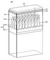
도 2는 본 발명의 제 1 실시예에 따른 히트 싱크를 가지는 초음파 프로브를 도시한 사시도이고, 도 3은 본 발명의 제 1 실시예에 따른 히트 싱크를 가지는 초음파 프로브를 도시한 측단면도이다. 도시된 바와 같이, 본 발명의 제 1 실시예에 따른 히트 싱크를 가지는 초음파 프로브(100)는 환자와 접촉하는 전면부부터 음향렌즈(Acoustic lens; 110), 정합층(120), 압전체(130) 및 후면층(140)이 배열되고, 후면층(140)에 히트 싱크(Heat sink; 150)가 마련된다.2 is a perspective view illustrating an ultrasonic probe having a heat sink according to a first embodiment of the present invention, and FIG. 3 is a side cross-sectional view illustrating an ultrasonic probe having a heat sink according to a first embodiment of the present invention. As shown, the
음향렌즈(110)는 정합층(120)의 전면에 덮여지도록 형성되어 초음파를 집속한다.The
정합층(120)은 압전체(130)의 초음파 송/수신면의 전극상에 형성되어 초음파의 반사율과 효율을 증가시킨다.The matching
압전체(130)는 후면층(140)의 전면에 접합되고, FPCB(Flexible Printed Circuit Board; 160)에 의해 메인 PCB(미도시)에 연결되는 1차 전극과 2차 전극이 양측면에 각각 마련되며, 전기적 신호를 음향신호인 초음파로 변환시켜 공기 중으로 내보내고, 공기 중에서 반사되어 돌아오는 초음파 반사신호를 다시 전기적 신호로 변환시켜서 장치로 보내는 역할을 한다.The
후면층(140)은 방열을 위한 히트 싱크(150)와 결합되고, 후방으로 방출되는 불필요한 초음파를 흡수하는데, 히트 싱크(150)와의 결합을 위하여 히트 싱크(150)에 몰딩으로 성형 제작될 수 있다.The
히트 싱트(150)는 열전도도가 높은 재질, 예컨대 알루미늄(Al), 구리(Cu) 등의 금속으로 제작되고, 후면층(140)의 후면(141), 즉 후면층(140)에서 압전체(130)가 접합되는 측의 반대면에 고정되며, 케이스(170)에 위치한 상태에서 실리콘(Silicon)의 메움에 의해 고정된다.The
히트 싱트(150)는 후면층(140)으로부터 열전도성을 높이기 위하여 후면층(140)의 후면에 요철 결합됨이 바람직하며, 이를 위해 몸체(151)의 일측면에 후면층(140)으로부터 열이 전도되기 위한 열전도돌기(152)가 다수로 형성됨으로써 열 전도돌기(152)와 상응하는 형상을 가지도록 후면층(140)에 형성되는 열전도홈(142)에 열전도돌기(152)가 각각 삽입된다. 따라서, 후면층(140)은 열전도홈(142)이 열전도돌기(152)와 상응하는 형상을 가짐으로써 열전도홈(142)과 열전도돌기(152)의 밀착도를 높이며, 이로 인해 열전도 효율을 높이게 된다.
열전도돌기(152)는 도 4에 도시된 바와 같이, 바(Bar) 형상으로 이루어지며, 열전도홈(142)을 통해 접속되는 후면층(140)과의 접촉면적을 극대화시킨다.As shown in FIG. 4, the
이와 같은 구성을 가지는 본 발명의 제 1 실시예에 따른 히트 싱크를 가지는 초음파 프로브(100)는 압전체(130)로부터 발생한 열이 후면층(140)을 통해서 히트 싱크(150)로 전도되어 방출됨으로써 후면층(140)으로의 열 확산 속도를 높이게 된다. 특히, 후면층(140)의 열전도홈(142) 각각에 히트 싱크(150)의 열전도돌기(152)가 결합되는 구조를 가짐으로써 후면층(140)과 히트 싱크(150)간의 접촉 면적이 확대됨으로써 후면층(140)으로부터 히트 싱크(150)로의 열전도 효율을 높인다.In the
이와 같이, 압전체(130)로부터 발생한 열이 히트 싱크(150)를 통해 신속하게 방출됨으로써 압전체(130)를 열로부터 보호하여 특성 저하를 방지함과 아울러 후면층(140)이 초음파 감쇄 특성을 그대로 유지하도록 하고, 이로 인해 초음파 프로브(100) 자체의 성능 저하 및 내구성 약화를 방지하며, 음향렌즈(110)로의 열전도를 감소시킴으로써 환자와의 접촉면 온도를 감소시킨다.As such, the heat generated from the
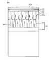
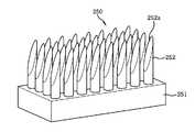
도 5는 본 발명의 제 2 실시예에 따른 히트 싱크를 가지는 초음파 프로브를 도시한 사시도이고, 도 6은 본 발명의 제 2 실시예에 따른 히트 싱크를 가지는 초음파 프로브를 도시한 측단면도이다. 도시된 바와 같이, 본 발명의 제 2 실시예에 따른 히트 싱크를 가지는 초음파 프로브(200)는 환자와 접촉하는 전면부부터 음향렌즈(210), 정합층(220), 압전체(230) 및 후면층(240)이 배열되고, 후면층(240)에 히트 싱크(250)가 마련된다. 본 실시예에서 히트 싱크(250)를 제외한 구성은 제 1 실시예에 따른 히트 싱크를 가지는 초음파 프로브(100)와 동일하므로 그 설명을 생략하기로 하겠다.5 is a perspective view illustrating an ultrasonic probe having a heat sink according to a second embodiment of the present invention, and FIG. 6 is a side cross-sectional view illustrating an ultrasonic probe having a heat sink according to a second embodiment of the present invention. As shown, the
히트 싱크(250)는 후면층(240)에 요철 결합되기 위하여 몸체(251)의 일측면에 열전도돌기(252)가 다수로 수직되게 형성됨으로써 후면층(240)의 열전도홈(242)에 각각 삽입되어 결합되는데, 도 7에 도시된 바와 같이, 열전도돌기(252)는 바(Bar) 형상으로 이루어지되, 끝단이 예각을 형성하도록 경사면(252a)을 가진다.The
한편, 후면층(240)은 열전도홈(242)이 열전도돌기(252)와 상응하는 형상을 가짐으로써 열전도돌기(252)의 전체 표면과 접속되는 구조를 가진다.On the other hand, the
이와 같은 구성을 가지는 본 발명의 제 2 실시예에 따른 히트 싱크를 가지는 초음파 프로브(200)는 압전체(230)로부터 발생한 열이 후면층(240)을 통해서 히트 싱크(250)로 신속하게 전도되어 방출됨으로써 압전체(230)의 특성 저하를 방지하여 초음파 프로브(200) 자체의 성능 저하 및 내구성 약화를 방지하며, 음향렌즈(210)의 온도 감소에 따른 환자와의 접촉면 온도를 낮추게 된다.In the
또한, 도 6에 도시된 바와 같이, 후면층(240)이 흡수한 초음파가 히트 싱크(250)의 열전도돌기(252)에 형성되는 경사면(252a)에 의해 측방향의 후면층(240)으로 반사됨으로써 전면으로 재반사되는 것을 억제시켜서 후면층(240) 내에 흡수되어 소멸되도록 한다. 따라서, 초음파의 후면반사음의 흡수라는 후면층(240) 본래의 목적을 달성하도록 하여 초음파 프로브(200)의 성능 저하를 방지한다.In addition, as illustrated in FIG. 6, ultrasonic waves absorbed by the
도 8은 본 발명의 제 3 실시예에 따른 히트 싱크를 가지는 초음파 프로브를 도시한 측단면도이고, 도 9는 본 발명의 제 3 실시예에 따른 히트 싱크를 가지는 초음파 프로브의 히트 싱크를 도시한 사시도이다. 도시된 바와 같이, 본 발명의 제 3 실시예에 따른 히트 싱크를 가지는 초음파 프로브(300)는 환자와 접촉하는 전면부부터 음향렌즈(310), 정합층(320), 압전체(330) 및 후면층(340)이 배열되고, 후면층(340)에 히트 싱크(350)가 마련된다. 본 실시예에서 히트 싱크(350)를 제외한 구성은 제 1 실시예에 따른 히트 싱크를 가지는 초음파 프로브(100)와 동일하므로 그 설명을 생략하기로 하겠다.8 is a side cross-sectional view illustrating an ultrasonic probe having a heat sink according to a third embodiment of the present invention, and FIG. 9 is a perspective view illustrating a heat sink of an ultrasonic probe having a heat sink according to a third embodiment of the present invention. to be. As shown, the
히트 싱크(350)는 후면층(340)에 요철 결합되기 위하여 몸체(351)의 일측면에 열전도돌기(352)가 다수로 수직되게 형성됨으로써 후면층(340)의 열전도홈(342)에 각각 삽입되어 결합되는데, 열전도돌기(352)는 바(Bar) 형상으로 이루어지되, 끝단으로부터 내측까지 연장되는 삽입홈(352a)이 형성된다.The
삽입홈(352a)은 후면층(340)이 흡수한 초음파가 히트 싱크(350)에 의해 전면으로 재반사되는 것을 방지하기 위하여 원뿔 형상으로 이루어진다.The
한편, 후면층(340)은 열전도홈(342)이 열전도돌기(352)와 상응하는 형상을 가짐으로써 열전도돌기(352)의 전체 표면과 접속되는 구조를 가진다. 즉 열전도홈(342)은 열전도돌기(352)가 삽입되는 형상을 가짐과 아울러 삽입홈(352a)에 삽입되기 위한 삽입돌기(342a)가 내측에 형성된다.On the other hand, the
이와 같은 구성을 가지는 본 발명의 제 3 실시예에 따른 히트 싱크를 가지는 초음파 프로브(300)는 압전체(330)로부터 발생한 열이 후면층(340)을 통해서 히트 싱크(350)로 신속하게 전도되어 방출됨으로써 압전체(330)의 특성 저하를 방지하여 초음파 프로브(300) 자체의 성능 저하 및 내구성 약화를 방지하며, 음향렌즈(310)의 온도 감소에 따른 환자와의 접촉면 온도를 낮추게 된다.In the
또한, 후면층(340)이 흡수한 초음파가 히트 싱크(350)의 삽입홈(352a) 내에서 반사를 반복하여 상쇄됨으로써 소멸되어 전면으로 재반사되는 것을 감소시키고, 이로 인해 초음파 프로브(300)의 성능 저하를 방지한다.In addition, the ultrasonic wave absorbed by the
도 10은 본 발명의 제 4 실시예에 따른 히트 싱크를 가지는 초음파 프로브를 도시한 측단면도이고, 도 11은 본 발명의 제 4 실시예에 따른 히트 싱크를 가지는 초음파 프로브의 히트 싱크를 도시한 사시도이다. 도시된 바와 같이, 본 발명의 제 4 실시예에 따른 히트 싱크를 가지는 초음파 프로브(400)는 환자와 접촉하는 전면부부터 음향렌즈(410), 정합층(420), 압전체(430) 및 후면층(440)이 배열되고, 후면층(440)에 히트 싱크(450)가 마련된다. 본 실시예에서 히트 싱크(450)를 제외한 구성은 제 1 실시예에 따른 히트 싱크를 가지는 초음파 프로브(100)와 동일하므로 그 설명을 생략하기로 하겠다.10 is a side cross-sectional view illustrating an ultrasonic probe having a heat sink according to a fourth embodiment of the present invention, and FIG. 11 is a perspective view illustrating a heat sink of an ultrasonic probe having a heat sink according to a fourth embodiment of the present invention. to be. As shown, the
히트 싱크(450)는 후면층(440)에 요철 결합되기 위하여 몸체(451)의 일측면에 열전도돌기(452)가 다수로 수직되게 형성됨으로써 후면층(440)에 열전도돌기(452)와 상응하는 형상을 가지는 열전도홈(442)에 각각 삽입되어 결합되는데, 열전도돌기(452)는 후면층(440)이 흡수한 초음파를 전면으로 재반사하는 것을 억제하기 위하여 원뿔 형상으로 이루어진다.The
한편, 후면층(440)은 열전도홈(442)이 열전도돌기(452)와 상응하는 형상, 즉 원뿔 형상을 가짐으로써 열전도돌기(452)의 전체 표면과 접속되는 구조를 가진다.On the other hand, the
이와 같은 구성을 가지는 본 발명의 제 4 실시예에 따른 히트 싱크를 가지는 초음파 프로브(400)는 이전의 실시예들과 마찬가지로 압전체(430)로부터 발생한 열이 후면층(440)을 통해서 히트 싱크(450)로 신속하게 전도되어 방출되도록 함으로써 압전체(430)의 특성 저하를 방지하여 초음파 프로브(400) 자체의 성능 저하 및 내구성 약화를 방지하며, 음향렌즈(410)의 온도 감소에 따른 환자와의 접촉면 온도를 낮추게 된다.In the
또한, 후면층(440)이 흡수한 초음파가 히트 싱크(450)의 원뿔형 열전도돌기(452)에 반사됨으로써 전면으로 재반사되지 않고 열전도돌기(452)의 측방향에 위치하는 후면층(440)으로 재흡수됨으로써 상쇄에 의해 소멸되고, 이로 인해 초음파 프로브(400)의 성능 저하를 방지한다.In addition, the ultrasonic wave absorbed by the
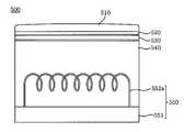
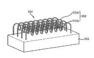
도 12는 본 발명의 제 5 실시예에 따른 히트 싱크를 가지는 초음파 프로브를 도시한 측단면도이고, 도 13은 본 발명의 제 5 실시예에 따른 히트 싱크를 가지는 초음파 프로브의 히트 싱크를 도시한 사시도이다. 도시된 바와 같이, 본 발명의 제 5 실시예에 따른 히트 싱크를 가지는 초음파 프로브(500)는 환자와 접촉하는 전면부부터 음향렌즈(510), 정합층(520), 압전체(530) 및 후면층(540)이 배열되고, 후면층(540)에 히트 싱크(550)가 마련된다. 본 실시예에서 후면층(540)과 히트 싱크(550)를 제외한 구성은 제 1 실시예에 따른 히트 싱크를 가지는 초음파 프로브(100)와 동일하므로 그 설명을 생략하기로 하겠다.12 is a side cross-sectional view illustrating an ultrasonic probe having a heat sink according to a fifth embodiment of the present invention, and FIG. 13 is a perspective view illustrating a heat sink of an ultrasonic probe having a heat sink according to a fifth embodiment of the present invention. to be. As shown, the
히트 싱크(550)는 후면층(540)과의 결합을 위하여 후면층(540)의 후면(541)에 삽입되어 고정되기 위한 삽입부(552)가 몸체(551)의 일측면에 형성된다.The
삽입부(552)는 후면층(540)으로부터 열전도율을 높이도록 코일 형상으로 이루어지는 와이어(552a)임이 바람직하다.The
코일 형태의 와이어(552a)는 다수로 이루어져서 일 예로 몸체(551)에 병렬로 배열되는데, 각각의 양단이 몸체(551)에 일체를 이루도록 형성되거나, 몸체(551)에 억지 끼워짐으로써 일체를 이루게 된다. 또한, 코일 형태의 와이어(552a)는 히트 싱크(550)의 몸체(551) 상에 후면층(540)이 몰딩으로 성형 제작됨으로써 후면층(540) 내측에 고정되고, 이로 인해 히트 싱크(550)의 몸체(551)와 후면층(540)이 서로 결합되도록 하며, 후면층(540)이 흡수한 초음파와의 간섭을 최소화하여 후면층(540)의 전면으로 초음파가 재반사하는 것을 억제한다.Coil-shaped
이와 같은 구성을 가지는 본 발명의 제 5 실시예에 따른 히트 싱크를 가지는 초음파 프로브(500)는 이전의 실시예들과 마찬가지로 압전체(530)로부터 발생한 열이 후면층(540)을 통해서 히트 싱크(550)로 신속하게 전도되어 방출되도록 함으로써 압전체(530)의 특성 저하를 방지하여 초음파 프로브(500) 자체의 성능 저하 및 내구성 약화를 방지하며, 음향렌즈(510)의 온도를 감소시킨다. 특히, 후면층(540)에 삽입된 코일 형태의 와이어(552a)가 후면층(540)으로부터 히트 싱크(550)로의 열전도 통로를 확대시키는 역할을 함으로써 열전도 효율을 높인다.In the
또한, 후면층(540)이 흡수한 초음파가 코일 형태의 와이어(552a) 사이를 통과하게 됨으로써 초음파가 후면층(540)의 전면으로 재반사됨을 억제하여 초음파 프 로브(500)의 성능 저하를 방지한다.In addition, the ultrasonic wave absorbed by the
이상과 같이, 본 발명의 바람직한 실시예들에 따르면, 압전체로부터 발생하는 열이 후면층을 통해서 히트 싱크로 신속하게 방출되도록 함으로써 압전체의 특성 저하를 억제하여 초음파 프로브의 성능 저하 및 내구성 약화를 방지하고, 음향렌즈의 발열을 방지함으로써 환자와의 접촉면 온도를 낮추도록 한다.As described above, according to preferred embodiments of the present invention, the heat generated from the piezoelectric material is quickly discharged to the heat sink through the rear layer, thereby suppressing the degradation of the piezoelectric property to prevent degradation of the ultrasonic probe and deterioration of durability. The temperature of the contact surface with the patient is lowered by preventing the acoustic lens from generating heat.
또한, 후면층이 흡수한 초음파가 전면으로 재반사되지 않도록 하여 초음파 프로브의 성능을 유지시키도록 하며, 열전도돌기가 흡수한 초음파를 전면으로 재반사하지 않는 형상을 가짐으로써 전면으로의 재반사 가능성으로 인해 압전체에 가까이 장착하지 못하는 단점을 극복하여 후면층으로의 열전도를 극대화할 수 있다.In addition, the ultrasonic wave absorbed by the rear layer is prevented from being reflected back to the front to maintain the performance of the ultrasonic probe. Due to this, it is possible to maximize the thermal conductivity to the rear layer by overcoming the disadvantage of not being mounted close to the piezoelectric body.
이상에서와 같이, 본 발명의 상세한 설명에서 구체적인 실시예에 관해 설명하였으나, 본 발명의 기술이 당업자에 의하여 용이하게 변형 실시될 가능성이 자명하며, 이러한 변형된 실시예들은 본 발명의 특허청구범위에 기재된 기술사상에 포함된다할 것이다.While the present invention has been particularly shown and described with reference to exemplary embodiments thereof, it is evident that many alternatives, modifications and variations will be apparent to those skilled in the art. And will be included in the described technical idea.
도 1은 종래의 기술에 따른 의료용 초음파 프로브를 도시한 단면도이고,1 is a cross-sectional view showing a medical ultrasound probe according to the prior art,
도 2는 본 발명의 제 1 실시예에 따른 히트 싱크를 가지는 초음파 프로브를 도시한 사시도이고,2 is a perspective view illustrating an ultrasonic probe having a heat sink according to a first embodiment of the present invention;
도 3은 본 발명의 제 1 실시예에 따른 히트 싱크를 가지는 초음파 프로브를 도시한 측단면도이고,3 is a side cross-sectional view showing an ultrasonic probe having a heat sink according to a first embodiment of the present invention,
도 4는 본 발명의 제 1 실시예에 따른 히트 싱크를 가지는 초음파 프로브의 히트 싱크를 도시한 사시도이고,4 is a perspective view illustrating a heat sink of an ultrasonic probe having a heat sink according to a first embodiment of the present invention;
도 5는 본 발명의 제 2 실시예에 따른 히트 싱크를 가지는 초음파 프로브를 도시한 사시도이고,5 is a perspective view illustrating an ultrasonic probe having a heat sink according to a second embodiment of the present invention;
도 6은 본 발명의 제 2 실시예에 따른 히트 싱크를 가지는 초음파 프로브를 도시한 측단면도이고,6 is a side cross-sectional view showing an ultrasonic probe having a heat sink according to a second embodiment of the present invention;
도 7은 본 발명의 제 2 실시예에 따른 히트 싱크를 가지는 초음파 프로브의 히트 싱트를 도시한 사시도이고,7 is a perspective view illustrating a heat sink of an ultrasonic probe having a heat sink according to a second embodiment of the present invention;
도 8은 본 발명의 제 3 실시예에 따른 히트 싱크를 가지는 초음파 프로브를 도시한 측단면도이고,8 is a side cross-sectional view showing an ultrasonic probe having a heat sink according to a third embodiment of the present invention;
도 9는 본 발명의 제 3 실시예에 따른 히트 싱크를 가지는 초음파 프로브의 히트 싱크를 도시한 사시도이고,9 is a perspective view illustrating a heat sink of an ultrasonic probe having a heat sink according to a third embodiment of the present invention;
도 10은 본 발명의 제 4 실시예에 따른 히트 싱크를 가지는 초음파 프로브를 도시한 측단면도이고,10 is a side cross-sectional view showing an ultrasonic probe having a heat sink according to a fourth embodiment of the present invention,
도 11은 본 발명의 제 4 실시예에 따른 히트 싱크를 가지는 초음파 프로브의 히트 싱크를 도시한 사시도이고,11 is a perspective view illustrating a heat sink of an ultrasonic probe having a heat sink according to a fourth embodiment of the present invention;
도 12는 본 발명의 제 5 실시예에 따른 히트 싱크를 가지는 초음파 프로브를 도시한 측단면도이고,12 is a side cross-sectional view showing an ultrasonic probe having a heat sink according to a fifth embodiment of the present invention;
도 13은 본 발명의 제 5 실시예에 따른 히트 싱크를 가지는 초음파 프로브의 히트 싱크를 도시한 사시도이다.13 is a perspective view illustrating a heat sink of an ultrasonic probe having a heat sink according to a fifth embodiment of the present invention.
<도면의 주요 부분에 대한 부호의 설명><Explanation of symbols for the main parts of the drawings>
110,210,310,410,510 : 음향렌즈 120,220,320,420,520 : 정합층110,210,310,410,510: Acoustic lens 120,220,320,420,520: Matching layer
130,230,330,430,530 : 압전체 140,240,340,440,540 : 후면층130,230,330,430,530: Piezoelectric 140,240,340,440,540: Back layer
141,541 : 후면 142,242,342,442, : 열전도홈141,541: Rear 142,242,342,442,: Thermally conductive groove
150,250,350,450,550 : 히트 싱크 151,251,351,451,551 : 몸체150,250,350,450,550: Heat sink 151,251,351,451,551: Body
152,252,352,452 : 열전도돌기 160 : FPCB152,252,352,452: heat conduction protrusion 160: FPCB
170 : 케이스 252a : 경사면170:
342a : 삽입돌기 352a : 삽입홈342a:
552 : 삽입부 552a : 와이어552:
Claims (10)
Translated fromKoreanPriority Applications (6)
| Application Number | Priority Date | Filing Date | Title |
|---|---|---|---|
| KR1020080071290AKR101018626B1 (en) | 2008-07-22 | 2008-07-22 | Ultrasonic Probe with Heat Sink |
| CN2009801285123ACN102098965A (en) | 2008-07-22 | 2009-07-06 | Ultrasonic probe having heat sink |
| EP09800515AEP2309930A4 (en) | 2008-07-22 | 2009-07-06 | Ultrasonic probe having heat sink |
| PCT/KR2009/003677WO2010011034A1 (en) | 2008-07-22 | 2009-07-06 | Ultrasonic probe having heat sink |
| JP2011519975AJP2011528929A (en) | 2008-07-22 | 2009-07-06 | Ultrasonic probe with heat sink |
| US13/054,092US20110114303A1 (en) | 2008-07-22 | 2009-07-06 | Ultrasonic probe having heat sink |
Applications Claiming Priority (1)
| Application Number | Priority Date | Filing Date | Title |
|---|---|---|---|
| KR1020080071290AKR101018626B1 (en) | 2008-07-22 | 2008-07-22 | Ultrasonic Probe with Heat Sink |
Publications (2)
| Publication Number | Publication Date |
|---|---|
| KR20100010358A KR20100010358A (en) | 2010-02-01 |
| KR101018626B1true KR101018626B1 (en) | 2011-03-03 |
Family
ID=41570461
Family Applications (1)
| Application Number | Title | Priority Date | Filing Date |
|---|---|---|---|
| KR1020080071290AActiveKR101018626B1 (en) | 2008-07-22 | 2008-07-22 | Ultrasonic Probe with Heat Sink |
Country Status (6)
| Country | Link |
|---|---|
| US (1) | US20110114303A1 (en) |
| EP (1) | EP2309930A4 (en) |
| JP (1) | JP2011528929A (en) |
| KR (1) | KR101018626B1 (en) |
| CN (1) | CN102098965A (en) |
| WO (1) | WO2010011034A1 (en) |
Cited By (1)
| Publication number | Priority date | Publication date | Assignee | Title |
|---|---|---|---|---|
| WO2015194733A1 (en)* | 2014-06-19 | 2015-12-23 | 주식회사 휴먼스캔 | Ultrasonic wave-dissipation block and ultrasonic probe having same |
Families Citing this family (23)
| Publication number | Priority date | Publication date | Assignee | Title |
|---|---|---|---|---|
| JPWO2011132531A1 (en)* | 2010-04-23 | 2013-07-18 | 株式会社日立メディコ | Ultrasonic probe, method for manufacturing the same, and ultrasonic diagnostic apparatus |
| CN103069844B (en)* | 2010-08-20 | 2016-01-06 | 株式会社日立医疗器械 | Ultrasonic probe and its diagnostic ultrasound equipment of use |
| DE102010062593A1 (en)* | 2010-12-08 | 2012-06-14 | Robert Bosch Gmbh | Ultrasonic sensor with a damping device and use thereof |
| US8841823B2 (en)* | 2011-09-23 | 2014-09-23 | Ascent Ventures, Llc | Ultrasonic transducer wear cap |
| US9072487B2 (en)* | 2012-05-11 | 2015-07-07 | General Electric Company | Ultrasound probe thermal drain |
| KR20150025066A (en)* | 2013-08-28 | 2015-03-10 | 삼성메디슨 주식회사 | Ultrasonic probe and manufacturing method thereof |
| KR101613413B1 (en)* | 2013-12-09 | 2016-04-19 | 삼성메디슨 주식회사 | Ultrasonic diagnostic instrument and manufacturing method thereof |
| JP5923539B2 (en)* | 2014-03-20 | 2016-05-24 | 富士フイルム株式会社 | Ultrasonic probe |
| KR102373132B1 (en)* | 2014-12-26 | 2022-03-11 | 삼성메디슨 주식회사 | An ultrasonic probe apparatus and an ultrasonic imaging apparatus using the same |
| JP6564615B2 (en)* | 2015-05-22 | 2019-08-21 | スタンレー電気株式会社 | Lighting device |
| US20180028159A1 (en)* | 2016-07-29 | 2018-02-01 | Butterfly Network, Inc. | Rearward acoustic diffusion for ultrasound-on-a-chip transducer array |
| CN110049728A (en)* | 2016-12-13 | 2019-07-23 | 蝴蝶网络有限公司 | Acoustic lens and its application |
| US10797221B2 (en)* | 2017-02-24 | 2020-10-06 | Baker Hughes, A Ge Company, Llc | Method for manufacturing an assembly for an ultrasonic probe |
| WO2019237256A1 (en)* | 2018-06-12 | 2019-12-19 | 深圳市理邦精密仪器股份有限公司 | Ultrasound transducer, ultrasonic probe, and ultrasonic detection apparatus |
| WO2020062259A1 (en)* | 2018-09-30 | 2020-04-02 | 深圳迈瑞生物医疗电子股份有限公司 | Ultrasound probe and surface array ultrasound probe |
| WO2020062272A1 (en)* | 2018-09-30 | 2020-04-02 | 深圳迈瑞生物医疗电子股份有限公司 | Ultrasound probe and area array ultrasound probe |
| WO2020062274A1 (en)* | 2018-09-30 | 2020-04-02 | 深圳迈瑞生物医疗电子股份有限公司 | Ultrasonic probe |
| CN110960253B (en)* | 2018-09-30 | 2025-09-16 | 深圳迈瑞生物医疗电子股份有限公司 | Ultrasonic probe and area array ultrasonic probe |
| WO2020062270A1 (en)* | 2018-09-30 | 2020-04-02 | 深圳迈瑞生物医疗电子股份有限公司 | Ultrasonic probe |
| CN110960257A (en)* | 2018-09-30 | 2020-04-07 | 深圳迈瑞生物医疗电子股份有限公司 | Ultrasonic probe and area array ultrasonic probe |
| CN114555247B (en)* | 2019-10-10 | 2023-09-01 | 新宁研究院 | System and method for cooling ultrasound transducers and ultrasound transducer arrays |
| JP7403358B2 (en)* | 2020-03-16 | 2023-12-22 | テルモ株式会社 | ultrasonic probe |
| KR20220133355A (en) | 2021-03-24 | 2022-10-05 | 삼성전자주식회사 | Probe for semiconductor device test and probe card including the same |
Citations (4)
| Publication number | Priority date | Publication date | Assignee | Title |
|---|---|---|---|---|
| JPH01293851A (en)* | 1988-05-23 | 1989-11-27 | Yokogawa Medical Syst Ltd | Ultrasonic probe |
| JPH08140973A (en)* | 1994-11-25 | 1996-06-04 | Toshiba Ceramics Co Ltd | Ultrasonic generator |
| JP2007244583A (en)* | 2006-03-15 | 2007-09-27 | Aloka Co Ltd | Ultrasonic diagnostic equipment |
| KR20080061012A (en)* | 2006-12-27 | 2008-07-02 | 주식회사 하이닉스반도체 | Semiconductor package |
Family Cites Families (18)
| Publication number | Priority date | Publication date | Assignee | Title |
|---|---|---|---|---|
| US5545942A (en)* | 1994-11-21 | 1996-08-13 | General Electric Company | Method and apparatus for dissipating heat from a transducer element array of an ultrasound probe |
| US6208513B1 (en)* | 1995-01-17 | 2001-03-27 | Compaq Computer Corporation | Independently mounted cooling fins for a low-stress semiconductor package |
| US5629906A (en)* | 1995-02-15 | 1997-05-13 | Hewlett-Packard Company | Ultrasonic transducer |
| US5602718A (en)* | 1995-09-29 | 1997-02-11 | Hewlett-Packard Company | Thermal sink for a transducer assembly |
| US5622175A (en)* | 1995-09-29 | 1997-04-22 | Hewlett-Packard Company | Miniaturization of a rotatable sensor |
| US5721463A (en)* | 1995-12-29 | 1998-02-24 | General Electric Company | Method and apparatus for transferring heat from transducer array of ultrasonic probe |
| AT413163B (en)* | 2001-12-18 | 2005-11-15 | Fotec Forschungs Und Technolog | COOLING DEVICE FOR A CHIP AND METHOD OF MANUFACTURE |
| US20040002655A1 (en)* | 2002-06-27 | 2004-01-01 | Acuson, A Siemens Company | System and method for improved transducer thermal design using thermo-electric cooling |
| JP2004063898A (en)* | 2002-07-30 | 2004-02-26 | Hitachi Cable Ltd | Heat radiating material and method of manufacturing the same |
| JP2005026248A (en)* | 2003-06-30 | 2005-01-27 | Enplas Corp | Heat radiating member for electric component |
| JP4624659B2 (en)* | 2003-09-30 | 2011-02-02 | パナソニック株式会社 | Ultrasonic probe |
| TWI381494B (en)* | 2004-01-07 | 2013-01-01 | Jisouken Co Ltd | Cooling device |
| JP4643227B2 (en)* | 2004-11-04 | 2011-03-02 | 株式会社東芝 | Ultrasonic probe and ultrasonic diagnostic apparatus |
| EP1825814B1 (en)* | 2004-12-09 | 2013-02-20 | Hitachi Medical Corporation | Ultrasonic probe |
| WO2007032056A1 (en)* | 2005-09-13 | 2007-03-22 | Mitsubishi Denki Kabushiki Kaisha | Heat sink |
| JP5065593B2 (en)* | 2005-11-30 | 2012-11-07 | 株式会社東芝 | Ultrasonic probe and ultrasonic imaging device |
| US7281573B2 (en)* | 2005-12-14 | 2007-10-16 | Hua-Hsin Tsai | Cooler |
| JP2008084965A (en)* | 2006-09-26 | 2008-04-10 | Seiko Epson Corp | Electronic device, heat dissipation substrate and electronic device |
- 2008
- 2008-07-22KRKR1020080071290Apatent/KR101018626B1/enactiveActive
- 2009
- 2009-07-06USUS13/054,092patent/US20110114303A1/ennot_activeAbandoned
- 2009-07-06JPJP2011519975Apatent/JP2011528929A/enactivePending
- 2009-07-06CNCN2009801285123Apatent/CN102098965A/enactivePending
- 2009-07-06EPEP09800515Apatent/EP2309930A4/ennot_activeWithdrawn
- 2009-07-06WOPCT/KR2009/003677patent/WO2010011034A1/enactiveApplication Filing
Patent Citations (4)
| Publication number | Priority date | Publication date | Assignee | Title |
|---|---|---|---|---|
| JPH01293851A (en)* | 1988-05-23 | 1989-11-27 | Yokogawa Medical Syst Ltd | Ultrasonic probe |
| JPH08140973A (en)* | 1994-11-25 | 1996-06-04 | Toshiba Ceramics Co Ltd | Ultrasonic generator |
| JP2007244583A (en)* | 2006-03-15 | 2007-09-27 | Aloka Co Ltd | Ultrasonic diagnostic equipment |
| KR20080061012A (en)* | 2006-12-27 | 2008-07-02 | 주식회사 하이닉스반도체 | Semiconductor package |
Cited By (3)
| Publication number | Priority date | Publication date | Assignee | Title |
|---|---|---|---|---|
| WO2015194733A1 (en)* | 2014-06-19 | 2015-12-23 | 주식회사 휴먼스캔 | Ultrasonic wave-dissipation block and ultrasonic probe having same |
| KR101607245B1 (en)* | 2014-06-19 | 2016-03-30 | 주식회사 휴먼스캔 | Block for dissipating ultrasonic and ultra sonic probe having the same |
| US10231699B2 (en) | 2014-06-19 | 2019-03-19 | Humanscan Co., Ltd | Ultrasonic wave-dissipation block and ultrasonic probe having same |
Also Published As
| Publication number | Publication date |
|---|---|
| CN102098965A (en) | 2011-06-15 |
| US20110114303A1 (en) | 2011-05-19 |
| JP2011528929A (en) | 2011-12-01 |
| WO2010011034A1 (en) | 2010-01-28 |
| EP2309930A4 (en) | 2011-10-05 |
| EP2309930A1 (en) | 2011-04-20 |
| KR20100010358A (en) | 2010-02-01 |
Similar Documents
| Publication | Publication Date | Title |
|---|---|---|
| KR101018626B1 (en) | Ultrasonic Probe with Heat Sink | |
| JP5904732B2 (en) | Ultrasonic probe and ultrasonic diagnostic apparatus | |
| JP4843395B2 (en) | Ultrasonic probe | |
| CN104755032B (en) | Ultrasonic probe | |
| KR101196214B1 (en) | Probe for ultrasonic diagnostic apparatus | |
| CN1897876B (en) | Ultrasonic probe | |
| KR101457666B1 (en) | Ultrasound Transducer with cooling function | |
| JP2000184497A (en) | Ultrasonic probe | |
| JP2005103078A (en) | Ultrasonic probe | |
| CN115038938A (en) | Ultrasound transducer, backing structure, and related methods | |
| TW201815353A (en) | Rearward acoustic diffusion for ultrasound-on-a-chip transducer array | |
| JP2007209699A (en) | Ultrasonic probe | |
| JP4602013B2 (en) | Ultrasonic probe | |
| CN108451544B (en) | Ultrasonic imaging diagnosis array probe and its manufacturing method and equipment | |
| JP2011229976A (en) | Ultrasonic probe and ultrasonic imaging apparatus | |
| JP4632800B2 (en) | Ultrasonic probe | |
| US8237335B2 (en) | Thermally enhanced ultrasound transducer means | |
| JPH1094540A (en) | Ultrasonic probe | |
| CN110960253B (en) | Ultrasonic probe and area array ultrasonic probe | |
| JP2000165995A (en) | Ultrasonic probe | |
| JP6608532B2 (en) | Ultrasonic probe and ultrasonic endoscope | |
| CN210170072U (en) | Ultrasonic probe | |
| KR20160101144A (en) | Heat radiation structure of ultrasonic transducer | |
| JP6122090B1 (en) | Ultrasonic probe | |
| JP2004329495A (en) | Ultrasonic probe |
Legal Events
| Date | Code | Title | Description |
|---|---|---|---|
| A201 | Request for examination | ||
| PA0109 | Patent application | Patent event code:PA01091R01D Comment text:Patent Application Patent event date:20080722 | |
| PA0201 | Request for examination | ||
| PG1501 | Laying open of application | ||
| E902 | Notification of reason for refusal | ||
| PE0902 | Notice of grounds for rejection | Comment text:Notification of reason for refusal Patent event date:20100531 Patent event code:PE09021S01D | |
| E701 | Decision to grant or registration of patent right | ||
| PE0701 | Decision of registration | Patent event code:PE07011S01D Comment text:Decision to Grant Registration Patent event date:20101129 | |
| GRNT | Written decision to grant | ||
| PR0701 | Registration of establishment | Comment text:Registration of Establishment Patent event date:20110223 Patent event code:PR07011E01D | |
| PR1002 | Payment of registration fee | Payment date:20110224 End annual number:3 Start annual number:1 | |
| PG1601 | Publication of registration | ||
| FPAY | Annual fee payment | Payment date:20140124 Year of fee payment:4 | |
| PR1001 | Payment of annual fee | Payment date:20140124 Start annual number:4 End annual number:4 | |
| FPAY | Annual fee payment | Payment date:20150212 Year of fee payment:5 | |
| PR1001 | Payment of annual fee | Payment date:20150212 Start annual number:5 End annual number:5 | |
| FPAY | Annual fee payment | Payment date:20160119 Year of fee payment:6 | |
| PR1001 | Payment of annual fee | Payment date:20160119 Start annual number:6 End annual number:6 | |
| FPAY | Annual fee payment | Payment date:20180220 Year of fee payment:8 | |
| PR1001 | Payment of annual fee | Payment date:20180220 Start annual number:8 End annual number:8 | |
| PR1001 | Payment of annual fee | Payment date:20210106 Start annual number:11 End annual number:11 | |
| PR1001 | Payment of annual fee | Payment date:20230106 Start annual number:13 End annual number:13 | |
| PR1001 | Payment of annual fee | Payment date:20240118 Start annual number:14 End annual number:14 |