KR101013873B1 - Integrated hybrid heat exchanger using head head - Google Patents
Integrated hybrid heat exchanger using head headDownload PDFInfo
- Publication number
- KR101013873B1 KR101013873B1KR1020080111177AKR20080111177AKR101013873B1KR 101013873 B1KR101013873 B1KR 101013873B1KR 1020080111177 AKR1020080111177 AKR 1020080111177AKR 20080111177 AKR20080111177 AKR 20080111177AKR 101013873 B1KR101013873 B1KR 101013873B1
- Authority
- KR
- South Korea
- Prior art keywords
- radiator
- internal combustion
- combustion engine
- heat exchanger
- tube
- Prior art date
- Legal status (The legal status is an assumption and is not a legal conclusion. Google has not performed a legal analysis and makes no representation as to the accuracy of the status listed.)
- Active
Links
Images


Classifications
- F—MECHANICAL ENGINEERING; LIGHTING; HEATING; WEAPONS; BLASTING
- F28—HEAT EXCHANGE IN GENERAL
- F28D—HEAT-EXCHANGE APPARATUS, NOT PROVIDED FOR IN ANOTHER SUBCLASS, IN WHICH THE HEAT-EXCHANGE MEDIA DO NOT COME INTO DIRECT CONTACT
- F28D1/00—Heat-exchange apparatus having stationary conduit assemblies for one heat-exchange medium only, the media being in contact with different sides of the conduit wall, in which the other heat-exchange medium is a large body of fluid, e.g. domestic or motor car radiators
- F28D1/02—Heat-exchange apparatus having stationary conduit assemblies for one heat-exchange medium only, the media being in contact with different sides of the conduit wall, in which the other heat-exchange medium is a large body of fluid, e.g. domestic or motor car radiators with heat-exchange conduits immersed in the body of fluid
- F28D1/04—Heat-exchange apparatus having stationary conduit assemblies for one heat-exchange medium only, the media being in contact with different sides of the conduit wall, in which the other heat-exchange medium is a large body of fluid, e.g. domestic or motor car radiators with heat-exchange conduits immersed in the body of fluid with tubular conduits
- F28D1/0408—Multi-circuit heat exchangers, e.g. integrating different heat exchange sections in the same unit or heat exchangers for more than two fluids
- F28D1/0426—Multi-circuit heat exchangers, e.g. integrating different heat exchange sections in the same unit or heat exchangers for more than two fluids with units having particular arrangement relative to the large body of fluid, e.g. with interleaved units or with adjacent heat exchange units in common air flow or with units extending at an angle to each other or with units arranged around a central element
- F28D1/0443—Combination of units extending one beside or one above the other
- F—MECHANICAL ENGINEERING; LIGHTING; HEATING; WEAPONS; BLASTING
- F01—MACHINES OR ENGINES IN GENERAL; ENGINE PLANTS IN GENERAL; STEAM ENGINES
- F01P—COOLING OF MACHINES OR ENGINES IN GENERAL; COOLING OF INTERNAL-COMBUSTION ENGINES
- F01P5/00—Pumping cooling-air or liquid coolants
- F01P5/10—Pumping liquid coolant; Arrangements of coolant pumps
- F—MECHANICAL ENGINEERING; LIGHTING; HEATING; WEAPONS; BLASTING
- F01—MACHINES OR ENGINES IN GENERAL; ENGINE PLANTS IN GENERAL; STEAM ENGINES
- F01P—COOLING OF MACHINES OR ENGINES IN GENERAL; COOLING OF INTERNAL-COMBUSTION ENGINES
- F01P11/00—Component parts, details, or accessories not provided for in, or of interest apart from, groups F01P1/00 - F01P9/00
- F—MECHANICAL ENGINEERING; LIGHTING; HEATING; WEAPONS; BLASTING
- F01—MACHINES OR ENGINES IN GENERAL; ENGINE PLANTS IN GENERAL; STEAM ENGINES
- F01P—COOLING OF MACHINES OR ENGINES IN GENERAL; COOLING OF INTERNAL-COMBUSTION ENGINES
- F01P3/00—Liquid cooling
- F01P3/18—Arrangements or mounting of liquid-to-air heat-exchangers
- F—MECHANICAL ENGINEERING; LIGHTING; HEATING; WEAPONS; BLASTING
- F28—HEAT EXCHANGE IN GENERAL
- F28F—DETAILS OF HEAT-EXCHANGE AND HEAT-TRANSFER APPARATUS, OF GENERAL APPLICATION
- F28F9/00—Casings; Header boxes; Auxiliary supports for elements; Auxiliary members within casings
- F28F9/02—Header boxes; End plates
- F28F9/0202—Header boxes having their inner space divided by partitions
- F28F9/0204—Header boxes having their inner space divided by partitions for elongated header box, e.g. with transversal and longitudinal partitions
- F28F9/0209—Header boxes having their inner space divided by partitions for elongated header box, e.g. with transversal and longitudinal partitions having only transversal partitions
- F—MECHANICAL ENGINEERING; LIGHTING; HEATING; WEAPONS; BLASTING
- F28—HEAT EXCHANGE IN GENERAL
- F28F—DETAILS OF HEAT-EXCHANGE AND HEAT-TRANSFER APPARATUS, OF GENERAL APPLICATION
- F28F9/00—Casings; Header boxes; Auxiliary supports for elements; Auxiliary members within casings
- F28F9/02—Header boxes; End plates
- F28F9/026—Header boxes; End plates with static flow control means, e.g. with means for uniformly distributing heat exchange media into conduits
- F28F9/027—Header boxes; End plates with static flow control means, e.g. with means for uniformly distributing heat exchange media into conduits in the form of distribution pipes
- F—MECHANICAL ENGINEERING; LIGHTING; HEATING; WEAPONS; BLASTING
- F01—MACHINES OR ENGINES IN GENERAL; ENGINE PLANTS IN GENERAL; STEAM ENGINES
- F01P—COOLING OF MACHINES OR ENGINES IN GENERAL; COOLING OF INTERNAL-COMBUSTION ENGINES
- F01P3/00—Liquid cooling
- F01P3/18—Arrangements or mounting of liquid-to-air heat-exchangers
- F01P2003/185—Arrangements or mounting of liquid-to-air heat-exchangers arranged in parallel
- F—MECHANICAL ENGINEERING; LIGHTING; HEATING; WEAPONS; BLASTING
- F01—MACHINES OR ENGINES IN GENERAL; ENGINE PLANTS IN GENERAL; STEAM ENGINES
- F01P—COOLING OF MACHINES OR ENGINES IN GENERAL; COOLING OF INTERNAL-COMBUSTION ENGINES
- F01P2050/00—Applications
- F01P2050/24—Hybrid vehicles
- F—MECHANICAL ENGINEERING; LIGHTING; HEATING; WEAPONS; BLASTING
- F28—HEAT EXCHANGE IN GENERAL
- F28D—HEAT-EXCHANGE APPARATUS, NOT PROVIDED FOR IN ANOTHER SUBCLASS, IN WHICH THE HEAT-EXCHANGE MEDIA DO NOT COME INTO DIRECT CONTACT
- F28D21/00—Heat-exchange apparatus not covered by any of the groups F28D1/00 - F28D20/00
- F28D2021/0019—Other heat exchangers for particular applications; Heat exchange systems not otherwise provided for
- F28D2021/0028—Other heat exchangers for particular applications; Heat exchange systems not otherwise provided for for cooling heat generating elements, e.g. for cooling electronic components or electric devices
- F28D2021/0031—Radiators for recooling a coolant of cooling systems
- F—MECHANICAL ENGINEERING; LIGHTING; HEATING; WEAPONS; BLASTING
- F28—HEAT EXCHANGE IN GENERAL
- F28D—HEAT-EXCHANGE APPARATUS, NOT PROVIDED FOR IN ANOTHER SUBCLASS, IN WHICH THE HEAT-EXCHANGE MEDIA DO NOT COME INTO DIRECT CONTACT
- F28D21/00—Heat-exchange apparatus not covered by any of the groups F28D1/00 - F28D20/00
- F28D2021/0019—Other heat exchangers for particular applications; Heat exchange systems not otherwise provided for
- F28D2021/008—Other heat exchangers for particular applications; Heat exchange systems not otherwise provided for for vehicles
- F28D2021/0091—Radiators
- F28D2021/0094—Radiators for recooling the engine coolant
Landscapes
- Engineering & Computer Science (AREA)
- Mechanical Engineering (AREA)
- General Engineering & Computer Science (AREA)
- Physics & Mathematics (AREA)
- Thermal Sciences (AREA)
- Chemical & Material Sciences (AREA)
- Combustion & Propulsion (AREA)
- Cooling, Air Intake And Gas Exhaust, And Fuel Tank Arrangements In Propulsion Units (AREA)
- Heat-Exchange Devices With Radiators And Conduit Assemblies (AREA)
- Hybrid Electric Vehicles (AREA)
Abstract
Translated fromKoreanDescription
Translated fromKorean본 발명은 하이브리드 차량에서 전장계 냉각 시스템과 내연기관 냉각 시스템을 하나로 통합하고, 또 시스템 내부의 기포를 용이하게 제거하여 냉각 효율을 향상시킨 수두차를 이용한 통합형 하이브리드 열교환기에 관한 것이다.The present invention relates to an integrated hybrid heat exchanger using a water head vehicle that integrates an electric field system cooling system and an internal combustion engine cooling system into a hybrid vehicle and easily removes bubbles in the system to improve cooling efficiency.
일반적으로 하이브리드 차량은 엔진과 모터를 탑재하여 이를 동시에 구동하거나, 선택적으로 구동하여 구동력을 얻는 차량이다.In general, a hybrid vehicle is a vehicle equipped with an engine and a motor to drive them simultaneously or selectively drive them to obtain driving force.
이러한 하이브리드 차량은 정속 주행 및 초기 구동시에는 모터에 의해 구동되며, 등판로 주행 또는 배터리 방전 모드시 내연기관에 의해 작동되어 연비를 향상시키는 장치이다.The hybrid vehicle is driven by a motor during constant speed driving and initial driving, and is operated by an internal combustion engine during driving on a climbing road or in a battery discharge mode to improve fuel efficiency.
여기서, 모터를 포함한 전기 부품은 작동시 열이 발생되고, 부품들의 입출력 특성을 최상의 상태로 유지하기 위하여 부품의 온도 상승을 억제하는 냉각장치를 설치할 필요가 있다.In this case, the electric parts including the motor generate heat during operation, and in order to maintain the input / output characteristics of the parts in the best state, it is necessary to install a cooling device that suppresses the temperature rise of the parts.
특히, 배터리의 경우에는 전체적인 충방전 효율을 최상으로 유지하기 위해서는 적정온도를 유지하여야 한다.In particular, in the case of a battery, in order to maintain the best overall charging and discharging efficiency, an appropriate temperature should be maintained.
그러므로 배터리의 충방전에 의해 발생되는 열은 냉각장치를 이용하여 냉각시켜 적정온도를 유지한다.Therefore, the heat generated by the charging and discharging of the battery is cooled by using a cooling device to maintain an appropriate temperature.
예를 들면, 하이브리드 차량의 경우, 모터 구동에 의한 주행시 인버터에서 전류의 상변화(교류→직류)에 의한 열과, 모터 및 발전기의 작동에 의한 열이 발생하는데, 이러한 전장계의 냉각을 위해 모터 구동시 전동 펌프→인버터→인버터 리저버 탱크→라디에이터로 냉각수가 순환되는 형태의 전장계 냉각 시스템을 구비하고 있다.For example, in the case of a hybrid vehicle, the inverter generates heat due to a phase change of current (alternating to direct current) in the inverter and a heat generated by the operation of the motor and the generator. An electric field-type cooling system is provided in which a coolant is circulated through a municipal electric pump, an inverter, an inverter reservoir tank, and a radiator.
따라서, 하이브리드 냉각 시스템은 구동원에 따라 전장계 냉각 시스템과 내연기관 냉각 시스템 등 2개의 냉각 시스템으로 운용된다.Therefore, the hybrid cooling system is operated by two cooling systems, an electric field system cooling system and an internal combustion engine cooling system, depending on the driving source.
이러한 하이브리드 냉각 시스템의 경우 내연기관 및 전장 모터 구동 유무, 워터 펌프의 유량, 냉각수의 온도에 따라 유체적으로 분리된 일체형 라디에이터의 내부 압력은 상호 다를 수가 있으며, 전압은 같더라도 동압은 다를 수 있다.In the hybrid cooling system, the internal pressures of the integrated radiator fluidically separated according to the presence or absence of the internal combustion engine and the electric motor, the flow rate of the water pump, and the temperature of the cooling water may be different, and the dynamic pressure may be different even though the voltage is the same.
최근에는 냉각효율의 향상, 레이아웃 설계의 유리함, 부품수 및 비용의 절감 등의 이점을 제공하는 통합형 냉각 시스템, 즉 전장계 냉각 시스템과 내연기관 냉각 시스템을 하나로 통합한 냉각 시스템이 제시되고 있다.Recently, an integrated cooling system that provides advantages of improved cooling efficiency, layout design advantages, reduced parts count and cost, that is, a cooling system integrating an electric field system cooling system and an internal combustion engine cooling system into one.
예를 들면, 일본 공개특허공보 특개평10-259721호와 미국 특허 US 6,124,644호에는 기존의 내연기관 라디에이터를 내연기관용과 전장용으로 분할 사용하고 있는 방식이 개시되어 있다.For example, Japanese Patent Application Laid-Open Nos. Hei 10-259721 and US Pat. No. 6,124,644 disclose a method in which an existing internal combustion engine radiator is divided into internal combustion engines and electric equipments.
그러나, 위의 일본 공개특허공보 특개평10-259721호의 경우, 전장용 라디에이터 내부에 석출된 기포가 탱크 상부로 포집되나, 배출구는 아래쪽 방향에 있어 리저버 탱크로 기포를 제거하는데 불리한 점이 있고, 이로 인해 냉각효율이 떨어지는 단점이 있다.However, in Japanese Unexamined Patent Application Publication No. 10-259721, bubbles deposited inside the electric radiator are collected to the upper part of the tank, but the discharge port is in a downward direction, which is disadvantageous in removing bubbles from the reservoir tank. There is a disadvantage of low cooling efficiency.
또한, 내연기관용 라디에이터와 전장용 라디에이터의 사용 온도 및 압력을 상이하게 설정하여 사용하고 있고, 내연기관용 라디에이터 또는 전장용 라디에이터의 어느 한쪽에 과도한 압력이 발생하는 경우, 두 라디에이터 사이의 압력 차이로 인해 코어부 변형 및 피로 파손 등이 발생하는 등 내구성 측면에서 불리한 점이 있다.In addition, when the operating temperature and pressure of the radiator for internal combustion engine and the electric radiator are set differently and used, and if excessive pressure is generated in either the radiator for internal combustion engine or the radiator for electric equipment, the core is caused by the pressure difference between the two radiators. There are disadvantages in terms of durability, such as negative deformation and fatigue failure.
그리고, 위의 미국 특허 US 6,124,644호의 경우, 라디에이터의 상부 탱크에 포집된 기포는 라디에이터 캡 오픈시에만 제거되는 대기 개방식으로 되어 있는데, 두 개의 섹션으로 분리된 라디에이터 중 크기가 작은 전장용 라디에이터의 탱크부는 포집공간의 부족으로 기포가 냉각수 유동을 방해하게 되어 냉각효율이 저하되는 단점이 있다.In addition, in the US Patent No. 6,124,644 above, the air bubbles collected in the upper tank of the radiator are air-opening type which is removed only when the radiator cap is opened, and the tank part of the small sized electric radiator among the radiators divided into two sections is The lack of a collecting space has a disadvantage that the bubbles interfere with the flow of cooling water, the cooling efficiency is lowered.
또한, 이것 역시 내연기관용 라디에이터와 전장용 라디에이터의 사용 온도 및 압력을 상이하게 설정하여 사용하고 있는 관계로, 위와 마찬가지로 내연기관용 라디에이터 또는 전장용 라디에이터의 어느 한쪽에 과도한 압력이 발생하는 경우, 두 라디에이터 사이의 압력 차이로 인해 코어부 변형 및 피로 파손 등이 발생하는 등 내구성 측면에서 불리한 점이 있다.In addition, this also uses a different setting temperature and pressure of the radiator for internal combustion engine and the electric radiator for use, and, as in the above, if excessive pressure is generated on either the internal combustion engine radiator or the electric radiator, between the two radiators Due to the pressure difference, there is a disadvantage in terms of durability, such as deformation of the core portion and fatigue failure.
따라서, 본 발명은 이와 같은 점을 감안하여 안출한 것으로서, 전장용 라디에이터와 내연기관용 라디에이터 간의 내부 압력 차이에 의해 유체 이동을 줄여 냉각수가 혼합되지 않고 각각 독립 유동이 가능한 구조를 유지하면서 일체형으로 통합하고, 각 라디에이터 내부를 연통하는 튜브를 구비하여 라디에이터 탱크 내의 기포를 효율적으로 배출시킬 수 있는 새로운 개념의 기포 제거 방식을 포함하는 냉각 시스템을 구현함으로써, 라디에이터 운전시 발생하는 기포를 효과적으로 제거할 수 있으며, 이에 따라 냉각 효율 향상을 도모할 수 있는 수두차를 이용한 통합형 하이브리드 열교환기를 제공하는데 그 목적이 있다.Therefore, the present invention has been devised in view of the above, by reducing the fluid movement by the internal pressure difference between the radiator for the electric field and the radiator for the internal combustion engine to integrate integrally while maintaining the structure that can be flowed independently without cooling water mixture, respectively In addition, by implementing a cooling system including a new concept of bubble elimination method for efficiently discharging bubbles in the radiator tank by having a tube communicating with each inside of the radiator, it is possible to effectively remove bubbles generated during the operation of the radiator, Accordingly, an object of the present invention is to provide an integrated hybrid heat exchanger using a head difference that can improve cooling efficiency.
상기 목적을 달성하기 위하여 본 발명에서 제공하는 수두차를 이용한 통합형 하이브리드 열교환기는 내연기관용 라디에이터부와 전장용 라디에이터부가 각각 냉각수의 독립 유동이 가능한 구조를 유지하면서 일체형으로 조합되고, 상기 내연기관용 라디에이터부 및 전장용 라디에이터부의 양쪽에 연결 설치되는 2개의 라디에이터 탱크는 내부가 적어도 1개 이상의 배플로 구획되는 동시에 각 라디에이터 탱크에는 내연기관용 냉각수 유입구 및 전장용 냉각수 유입구와 내연기관용 냉각수 배출구 및 전장용 냉각수 배출구가 설치되며, 상기 배플에는 상부로 연장되는 일정높이의 튜브가 설치되어 배플로 구획되어 있던 라디에이터 탱크 위아래 공간이 서 로 연통되는 구조로 이루어진 것을 특징으로 한다.In order to achieve the above object, the integrated hybrid heat exchanger using the water head provided by the present invention is integrally combined while maintaining a structure in which the radiator portion for the internal combustion engine and the radiator portion for the electric field are capable of independent flow of cooling water, respectively, and the radiator portion for the internal combustion engine and The two radiator tanks connected to both sides of the electric radiator unit are partitioned with at least one baffle inside, and each radiator tank is provided with a coolant inlet for the internal combustion engine and a coolant inlet for the internal combustion engine, a coolant outlet for the internal combustion engine, and a coolant outlet for the electric engine. The baffle is characterized in that the tube of a predetermined height extending upwardly is installed is made of a structure in which the space above and below the radiator tank partitioned baffle is in communication with each other.
이에 따라, 상기 수두차를 이용한 통합형 하이브리드 열교환기는 라디에이터 탱크의 아래쪽 공간에서 포집된 기포를 라디에이터 탱크의 윗쪽 공간을 통해 용이하게 제거할 수 있는 특징이 있다.Accordingly, the integrated hybrid heat exchanger using the water head can easily remove bubbles collected in the lower space of the radiator tank through the upper space of the radiator tank.
여기서, 상기 튜브는 기포는 배출하나 액상 유체의 이동을 최소화하며, 어느 한쪽 라디에이터부의 과도한 압력 상승시 바이패스 통로 역할을 수행하여 압력조절수단으로 이용될 수 있도록 하는 것이 바람직하다.Here, it is preferable that the tube discharges bubbles but minimizes movement of the liquid fluid, and serves as a bypass passage when excessive pressure rises in one of the radiator portions so as to be used as a pressure regulating means.
본 발명에서 제공하는 수두차를 이용한 통합형 하이브리드 열교환기는 다음과 같은 장점이 있다.Integrated hybrid heat exchanger using the water head provided by the present invention has the following advantages.
① 냉각 성능의 향상 - 라디에이터 탱크의 상부, 특히 전장계 라디에이터측 탱크의 상부에 포집된 기포 제거가 용이하여 시스템 내부의 기포 배출 기능을 개선할 수 있고, 따라서 냉각수 유동저항 개선과 열전도 효율을 증대할 수 있어 냉각 효율을 향상시킬 수 있다.① Improved cooling performance-It is easy to remove bubbles trapped in the upper part of the radiator tank, especially the upper part of the electric field radiator side tank, so that it is possible to improve the bubble discharge function inside the system, thus improving the cooling water flow resistance and the heat conduction efficiency. It can improve the cooling efficiency.
② 내연기관과 전장계 냉각 시스템 내 상이한 압력캡 사용이 가능 - 튜브의 수두차를 이용함으로써 기포는 쉽게 배출시킬 수 있으나, 냉각수의 유동은 주어진 조건 내에서 한시적으로 발생한다.② Different pressure caps can be used in internal combustion engine and electric field cooling system.-By using the tube head difference, bubbles can be easily discharged, but the flow of cooling water occurs for a limited time under given conditions.
③ 내구성 향상 - 튜브 연통 구조를 통해 기포는 배출하나 액상 유체의 이동을 최소화함과 동시에 일측의 과도한 압력을 수용하여 양측의 압력을 균일하게 할 수 있고, 이에 따라 두 라디에이터 사이의 압력 차이에 의한 코어부 변형 및 피로 파손을 방지할 수 있다.③ Improved durability-Through the tube communication structure, bubbles are discharged but the movement of liquid fluid can be minimized, while the excessive pressure on one side can be accommodated to equalize the pressure on both sides, and thus the core due to the pressure difference between the two radiators Negative deformation and fatigue breakage can be prevented.
④ 비용 감소 - 각각의 2개의 열교환기 적용시보다 1개의 헤더와 탱크에 전장 시스템 냉각용 코어부와 내연기관 냉각용 코어부를 적용함으로써 원가를 절감할 수 있다.④ Cost Reduction-Cost savings can be achieved by applying core system cooling cores and internal combustion engine cooling cores to one header and tank compared to two heat exchangers.
⑤ 공정 단축 - 클린칭 공정 1개소 삭제, 한번에 2개 이상의 코어부를 용접할 수 있다.⑤ Shortening process-One clinching process can be deleted, and two or more cores can be welded at a time.
⑥ 중량 감소 및 구조 단순화 - 2개의 열교환기 적용시보다 탱크와 헤더 각 1개씩 폐지로 중량을 줄일 수 있고 구조를 단순화할 수 있다.⑥ Weight reduction and structure simplification-It is possible to reduce weight and simplify the structure by scrapping one tank and one header each than two heat exchangers.
이하, 첨부한 도면을 참조하여 본 발명을 상세히 설명하면 다음과 같다.Hereinafter, the present invention will be described in detail with reference to the accompanying drawings.
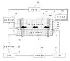
도 1은 본 발명의 일 실시예에 따른 수두차를 이용한 통합형 하이브리드 열교환기를 나타내는 개략도이다.1 is a schematic diagram showing an integrated hybrid heat exchanger using a head head according to an embodiment of the present invention.
도 1에 도시한 바와 같이, 전장계 냉각 시스템과 내연기관 냉각 시스템의 2개의 냉각 시스템을 채택하고 있는 하이브리드 냉각 시스템에서 통합형 열교환기는 각각의 독립된 유동구조를 갖는 전장용 라디에이터와 내연기관용 라디에이터를 하나의 일체형 구조로 조합하고, 여기에 라디에이터 간의 연통구조를 더 겸비함으로써, 냉각 시스템 가동시 발생하는 기포의 제거를 용이하게 할 수 있고, 기포는 배출하나 액상 유체의 이동을 최소화함과 동시에 라디에이터 내의 과도 압력 발생시 이를 적절히 수용하여 양측의 압력을 균일하게 할 수 있는 등 냉각 효율 향상과 코어부 변형이나 파손을 방지할 수 있도록 한 것이다.As shown in FIG. 1, in a hybrid cooling system employing two cooling systems, an electric field radiator and an internal combustion engine radiator, in a hybrid cooling system employing two cooling systems of an electric field cooling system and an internal combustion engine cooling system. By combining it into an integral structure and further combining the communication structure between the radiators, it is possible to facilitate the removal of air bubbles generated during operation of the cooling system, and to discharge the air bubbles while minimizing the movement of the liquid fluid, while at the same time the excessive pressure in the radiator When it occurs, it is appropriately accommodated so that the pressure on both sides can be uniformed, thereby improving the cooling efficiency and preventing the core part from being deformed or damaged.
이를 위하여, 내연기관용 라디에이터부(10)와 전장용 라디에이터부(11)가 위아래로 나란하게 배치되면서 각각 독립적인 냉각수의 유동 경로를 갖는 형태로 조합되고, 상기 내연기관용 라디에이터부(10) 및 전장용 라디에이터부(11)의 양쪽에는 각 라디에이터부측과 연통되는 라디에이터 탱크(12a),(12b)가 각각 설치되며, 특히 2개의 라디에이터 탱크(12a),(12b)의 내부에는 배플(13)이 설치되어 탱크 내부 공간은 위아래로 구획된다.To this end, the
이에 따라, 상기 라디에이터 탱크(12a),(12b)의 내부는 배플(13)을 기준하여 윗쪽으로는 내연기관용 라디에이터부(10)측과 통하게 되고, 아래쪽으로는 전장용 라디에이터부(11)측과 통하게 된다.Accordingly, the inside of the
냉각수의 유입과 배출을 위하여, 탱크 내부가 배플(13)로 구획되어 있는 라디에이터 탱크(12a),(12b)의 상부 공간측으로는 내연기관용 냉각수 유입구(14)와 내연기관용 냉각수 배출구(16)가 양편에 각각 설치되고, 하부 공간측으로는 전장용 냉각수 유입구(15)와 전장용 냉각수 배출구(17)가 양편에 각각 설치된다.For the inlet and outlet of the coolant, the upper space of the
여기서, 각 유입구의 위치는 배출구의 위치보다 높은 위치를 갖도록 하는 것이 바람직하다.Here, it is preferable that the position of each inlet is higher than the position of the outlet.
이러한 냉각수 유입구 및 배출구를 이용하여 내연기관 계통 및 전장 계통의 2가지 냉각회로를 구성할 수 있다.These cooling water inlets and outlets can be used to configure two cooling circuits, an internal combustion engine system and an electric field system.
예를 들면, 내연기관용 냉각수 배출구(16)→엔진 워터펌프(22)→내연기 관(23)→내연기관용 냉각수 유입구(15)로 이어지는 내연기관 계통의 냉각회로를 구성할 수 있고, 또 전장용 냉각수 배출구(17)→전동 워터펌프(25)→인버터(26)→리저버 탱크(24b)→ISG(25)→전장용 냉각수 유입구(14)로 이어지는 전장 계통의 냉각회로를 구성할 수 있다.For example, a cooling circuit of an internal combustion engine system that extends from the
또한, 상기 라디에이터 탱크(12a)의 상부에 설치되어 있는 캡(20)의 일측으로부터 연장되는 라인은 리저버(24a)측으로 연결된다.In addition, a line extending from one side of the
또한, 상기 내연기관용 라디에이터부(10)와 전장용 라디에이터부(11)는 필요한 열용량에 따라 코어의 두께를 다르게 설정할 수 있다.In addition, the
예를 들면, 전장 계통의 전장용품들이 대용량화되는 경우 전장용 라디에이터부(11)의 내부에 들어가는 코어들의 두께를 대용량 열교환에 적합한 크기로 설정할 수 있다.For example, when the electric equipment of the electric system is large in capacity, the thicknesses of the cores that enter the inside of the
특히, 본 발명에서는 배플(13)에 의해 구획되어 있는 라디에이터 탱크(12a),(12b)의 상하부 공간을 서로 연통시켜주는 구조를 제공한다.In particular, the present invention provides a structure in which the upper and lower spaces of the
이를 위하여, 상기 배플(13)에는 상부로 연장되는 일정높이의 튜브(18)가 적어도 1개 이상이 설치되며, 이에 따라 라디에이터 탱크(12a),(12b)의 위아래 공간이 서로 연통되므로서, 아래쪽 공간에서 포집된 기포가 윗쪽 공간으로 이동될 수 있다.To this end, the
여기서, 상기 튜브(18)의 높이는 라디에이터에 적용되는 압력, 유량 등을 고려한 캘리브레이션을 통해 적절히 설정할 수 있다.Here, the height of the
이때, 상기 튜브(18)는 배플(13)의 성형시 배플과 함께 일체형으로 형성할 수 있거나, 또 별도 제작 후 배플(13)에 끼워 삽입하는 방식으로 조립 설치할 수 있다.In this case, the
여기서, 상기 튜브(18)는 기포를 배출시키는 역할 이외에도 라디에이터 간의 압력차를 완충시키는 역할도 수행할 수 있다.Here, the
예를 들면, 내연기관용 라디에이터부(10)와 전장용 라디에이터부(11) 중에서 어느 한쪽의 압력이 과도하게 상승하는 경우, 튜브(18)가 양측을 연결하는 바이패스 통로의 역할을 수행하면서 기포는 배출하나 액상 유체의 이동을 최소화함과 동시에 압력조절수단의 기능을 발휘할 수 있으므로, 양측의 압력을 균일하게 해줄 수 있고, 결국 이러한 압력에 따른 부하를 수용할 수 있어 내구성을 높일 수 있다.For example, when the pressure of either of the
즉, 유체적으로 분리된 라디에이터는 일측에 과도한 압력 발생시, 두 라디에이터 사이의 압력 차이에 의한 코어부 변형 및 피로 파손이 발생할 수 있는데, 튜브의 통로는 양측의 압력차에 의한 소량의 순간적인 냉각수 유동 및 기포 유동으로 양측의 압력이 균일하게 되어 내구성을 확보할 수 있다.That is, the fluid separated radiator may cause core deformation and fatigue failure due to the pressure difference between the two radiators when excessive pressure is generated on one side, the passage of the tube is a small amount of instantaneous coolant flow due to the pressure difference between the two sides And by the bubble flow it is possible to ensure the pressure on both sides to be durable.
한편, 본 발명에서 제공하는 열교환기의 경우 내연기관 냉각 시스템과 전장계 냉각 시스템의 압력캡을 다르게 설정하여 사용할 수 있다.On the other hand, in the case of the heat exchanger provided by the present invention can be used by setting the pressure cap of the internal combustion engine cooling system and the electric field system cooling system differently.
예를 들면, 내연기관 냉각 시스템의 압력캡은 1.1bar로 설정하고, 전장계 냉각 시스템의 압력캡은 0.4bar로 설정할 수 있다.For example, the pressure cap of the internal combustion engine cooling system may be set to 1.1 bar, and the pressure cap of the electric field cooling system may be set to 0.4 bar.
이와 같은 조건을 갖는 열교환기에서 튜브(18)를 적용하는 경우, 만일 내연기관 냉각 시스템의 압력이 크다면, 압력차에 의해 내연기관용 라디에이터부의 상측에 포집된 기포가 라디에이터 탱크(12a)의 상측까지 연결된 튜브(18)를 통해 전 장용 라디에이터 탱크(12b)로 잠시 유동이 발생할 수도 있으나, 기포의 부력에 의해 다시 내연기관용 라디에이터부로 액상 냉각수 대비 먼저 재이동됨으로써 액상 냉각수의 유동을 최소화할 수 있고, 반대로 전장계 냉각 시스템의 압력이 클 경우에는 튜브(18)의 상단부 위치 에너지 차(비중량×높이차)보다 상하단부의 압력차가 클 경우에 한하여 순간적으로 냉각수가 내연기관용 라디에이터부로 이동이 가능할 수 있으나, 통상적으로 내연기관용 워터펌프 대비 전장용 워터펌프가 작고, 내연기관 냉각 시스템과 전장계 냉각 시스템 간의 압력차, 즉 양측 라디에이터 간의 압력차가 수두차보다 작기 때문에 양측 라디에이터의 압력을 다르게 설정하여 사용하는 경우에도 냉각수의 이동은 순간적으로만 발생하게 되고, 결국 냉각수의 이동이 제한적이므로 냉각수 유동과 관련한 문제는 크게 우려할 필요가 없다.In the case where the
즉, 압력차를 다르게 설정한 라디에이터에 튜브를 적용하여 연통시킨 경우에도 기포는 용이하게 제거할 수 있으며, 냉각수의 압력에 따른 유동은 제한적이고 순간적으로만 발생하게 되므로, 냉각수 유동과 관련한 문제는 완전히 배제할 수 있다.In other words, even when the tube is connected to a radiator with a different pressure difference, bubbles can be easily removed, and the flow of the coolant is limited and instantaneously generated. Can be excluded.
예를 들면, "(P2/γ-P1/γ)<h/γ" 의 경우 냉각수의 유동이 없게 된다.For example, in the case of "(P2 / γ-P1 / γ) <h / γ", there is no flow of cooling water.
반대의 경우 튜브의 길이가 극단적으로 짧은 경우이나 대다수의 경우에 내연기관용 라디에이터가 전장용 라디에이터에 비해 2배 정도 크다.In the opposite case, the tube length is extremely short, but in most cases the radiator for an internal combustion engine is about twice as large as a radiator for an electric vehicle.
또, "(P1/γ-P2/γ)<기포의 부력" 의 경우에도 냉각수의 유동이 없게 된다.Also, in the case of "(P1 / γ-P2 / γ) <buoyancy of bubbles", there is no flow of cooling water.
반대의 경우 기포의 유동이 하측으로 발생하다 다시 상측으로 이동하거나, 튜브 끝단 대비 상측에 위치한 냉각 일부분만 이동한다.In the opposite case, the bubble flows downward and then moves upwards, or only a portion of the cooling located above the tube end.
여기서, P1은 내연기관용 라디에이터부 압력, P2는 전장용 라디에이터부 압력, h는 위치에너지(튜브의 길이), γ는 냉각수의 비중량을 각각 나타낸다.Here, P1 represents the radiator portion pressure for the internal combustion engine, P2 represents the radiator portion pressure for the electric field, h represents potential energy (length of the tube), and γ represents the specific weight of the cooling water.
따라서, 이와 같이 구성된 수두차를 이용한 통합형 하이브리드 열교환기에서 운전 조건에 따른 냉각수의 흐름을 살펴보면 다음과 같다.Therefore, the flow of the cooling water according to the operating conditions in the integrated hybrid heat exchanger using the water head configured as described above is as follows.
도 2는 본 발명의 일 실시예에 따른 수두차를 이용한 통합형 하이브리드 열교환기에서 전장 구동시 냉각수 흐름을 나타내는 개략도이다.Figure 2 is a schematic diagram showing the coolant flow in the electric field driving in the integrated hybrid heat exchanger using the head head according to an embodiment of the present invention.
도 2에 도시한 바와 같이, 여기서는 차량의 속도가 40KPH 이하인 조건에서 전장 구동시의 냉각수 흐름을 보여준다.As shown in FIG. 2, the flow of coolant during full length driving is shown here under the condition that the speed of the vehicle is 40 KPH or less.
이때에는 엔진 워터펌프(22)의 미구동으로 내연기관 계통의 냉각회로에는 냉각수의 유동이 없다.At this time, there is no flow of cooling water in the cooling circuit of the internal combustion engine system due to the non-driving of the
전장 계통의 전동 워터펌프(25)로부터 송수된 비교적 고온의 냉각수는 전장용 냉각수 유입구(15)를 통해 라디에이터 탱크(12a)의 하측 공간으로 유입되고, 이렇게 유입된 냉각수는 전장용 라디에이터부(11)를 경유하면서 된 후, 계속해서 라디에이터 탱크(12b)에 있는 전장용 냉각수 배출구(17)를 통해 배출되어 전장 계통으로 보내진다.The relatively high temperature coolant flowed from the
이때, 라디에이터 탱크(12a),(12b)의 하측, 즉 배플(13)의 저면쪽에 포집된 기포는 튜브(18)를 통해 상측으로 이동되고, 최종적으로 리저버(24a)를 통해 제거될 수 있다.At this time, bubbles collected below the
물론, 일부의 기포는 리저버(24b)를 통해 제거될 수 있다.Of course, some bubbles can be removed through the
도 3은 본 발명의 일 실시예에 따른 수두차를 이용한 통합형 하이브리드 열 교환기에서 내연기관 구동시 냉각수 흐름을 나타내는 개략도이다.Figure 3 is a schematic diagram showing the coolant flow when driving the internal combustion engine in the integrated hybrid heat exchanger using the head difference according to an embodiment of the present invention.
도 3에 도시한 바와 같이, 내연기관 구동시에는 전동 워터펌프(25)의 미구동으로 전장 계통의 냉각회로에는 냉각수의 유동이 없다.As shown in Fig. 3, when the internal combustion engine is driven, there is no flow of cooling water in the cooling circuit of the electric system because the
내연기관 계통의 엔진 워터펌프(22)로부터 송수된 고온의 냉각수는 내연기관용 냉각수 유입구(14)를 통해 라디에이터 탱크(12a)의 상측 공간으로 유입되고, 이렇게 유입된 냉각수는 내연기관용 라디에이터부(10)를 경유하면서 냉각되며, 계속해서 냉각된 냉각수는 라디에이터 탱크(12b)에 있는 내연기관용 냉각수 배출구(16)를 통해 유입량 만큼 다시 내연기관측으로 보내진다.The high temperature coolant returned from the
이때에도 라디에이터 탱크(12a),(12b)의 상측 공간쪽에 포집된 기포는 최종적으로 리저버(24a)를 통해 제거될 수 있다.In this case, bubbles collected in the upper space of the
이와 같이, 내연기관 라디에이터와 전장계 라디에이터 간에 튜브를 이용한 연통 구조를 적용함으로써, 라디에이터 탱크의 하측에 포집된 기포의 제거가 용이하고, 결국 냉각 시스템 내의 기포 배출 기능을 향상시켜 내연기관 냉각 시스템 뿐만 아니라 전장계 냉각 시스템의 냉각성능을 크게 향상시킬 수 있다.In this way, by adopting a communication structure using a tube between the internal combustion engine radiator and the electric field radiator, it is easy to remove bubbles trapped in the lower side of the radiator tank, thereby improving the bubble discharge function in the cooling system to improve the internal combustion engine cooling system as well. The cooling performance of the electric field cooling system can be greatly improved.
도 1은 본 발명의 일 실시예에 따른 수두차를 이용한 통합형 하이브리드 열교환기를 나타내는 개략도1 is a schematic diagram showing an integrated hybrid heat exchanger using water head according to an embodiment of the present invention
도 2는 본 발명의 일 실시예에 따른 수두차를 이용한 통합형 하이브리드 열교환기에서 전장 구동시 냉각수 흐름을 나타내는 개략도Figure 2 is a schematic diagram showing the coolant flow during the electric field driving in the integrated hybrid heat exchanger using the head head according to an embodiment of the present invention
도 3은 본 발명의 일 실시예에 따른 수두차를 이용한 통합형 하이브리드 열교환기에서 내연기관 구동시 냉각수 흐름을 나타내는 개략도Figure 3 is a schematic diagram showing the coolant flow when driving the internal combustion engine in the integrated hybrid heat exchanger using the head head according to an embodiment of the present invention
<도면의 주요부분에 대한 부호의 설명><Description of the symbols for the main parts of the drawings>
10 : 내연기관용 라디에이터부 11 : 전장용 라디에이터부10: radiator part for internal combustion engine 11: radiator part for electric equipment
12a,12b : 라디에이터 탱크 13 : 배플12a, 12b: Radiator tank 13: Baffle
14 : 내연기관용 냉각수 유입구 15 : 전장용 냉각수 유입구14: Cooling water inlet for the internal combustion engine 15: Cooling water inlet for the electric
16 : 내연기관용 냉각수 배출구 17 : 전장용 냉각수 배출구16: Coolant outlet for internal combustion engine 17: Coolant outlet for electrical equipment
18 : 튜브 19 : 모세관18: tube 19: capillary tube
20 : 캡 21 : 헤더20: Cap 21: Header
22 : 엔진 워터펌프 23 : 내연기관22: engine water pump 23: internal combustion engine
24a,24b : 리저버 탱크 25 : 전동 워터펌프24a, 24b: Reservoir tank 25: Electric water pump
26 : 인버터 27 : ISG26: inverter 27: ISG
Claims (5)
Translated fromKoreanPriority Applications (3)
| Application Number | Priority Date | Filing Date | Title |
|---|---|---|---|
| KR1020080111177AKR101013873B1 (en) | 2008-11-10 | 2008-11-10 | Integrated hybrid heat exchanger using head head |
| US12/488,185US8430151B2 (en) | 2008-11-10 | 2009-06-19 | Integrated hybrid heat exchanger using water head difference |
| CN2009101495000ACN101738098B (en) | 2008-11-10 | 2009-06-25 | Integrated hybrid heat exchanger using water head differential |
Applications Claiming Priority (1)
| Application Number | Priority Date | Filing Date | Title |
|---|---|---|---|
| KR1020080111177AKR101013873B1 (en) | 2008-11-10 | 2008-11-10 | Integrated hybrid heat exchanger using head head |
Publications (2)
| Publication Number | Publication Date |
|---|---|
| KR20100052245A KR20100052245A (en) | 2010-05-19 |
| KR101013873B1true KR101013873B1 (en) | 2011-02-14 |
Family
ID=42164119
Family Applications (1)
| Application Number | Title | Priority Date | Filing Date |
|---|---|---|---|
| KR1020080111177AActiveKR101013873B1 (en) | 2008-11-10 | 2008-11-10 | Integrated hybrid heat exchanger using head head |
Country Status (3)
| Country | Link |
|---|---|
| US (1) | US8430151B2 (en) |
| KR (1) | KR101013873B1 (en) |
| CN (1) | CN101738098B (en) |
Families Citing this family (21)
| Publication number | Priority date | Publication date | Assignee | Title |
|---|---|---|---|---|
| FR2944235B1 (en)* | 2009-04-09 | 2012-10-19 | Renault Sas | COOLING DEVICE FOR MOTOR VEHICLE |
| ITBO20100012A1 (en)* | 2010-01-13 | 2011-07-14 | Ferrari Spa | COOLING SYSTEM FOR A VEHICLE WITH HYBRID PROPULSION |
| DE102010060319B4 (en)* | 2010-11-03 | 2012-05-31 | Ford Global Technologies, Llc. | cooling system |
| US20120168138A1 (en)* | 2010-12-30 | 2012-07-05 | Hyundai Motor Company | Integrated pump, coolant flow control and heat exchange device |
| US8459389B2 (en)* | 2010-12-30 | 2013-06-11 | Hyundai Motor Company | Integrated pump, coolant flow control and heat exchange device |
| JP5594197B2 (en)* | 2011-03-16 | 2014-09-24 | コベルコ建機株式会社 | Construction machine cooling structure |
| KR101353413B1 (en)* | 2011-09-22 | 2014-01-22 | 한라비스테온공조 주식회사 | Automotive Cooling Module |
| KR101283887B1 (en)* | 2011-12-07 | 2013-07-08 | 현대자동차주식회사 | Radiator for vehicle |
| KR101316268B1 (en)* | 2011-12-09 | 2013-10-08 | 현대자동차주식회사 | Variable Capacity Core type Heat Exchanger Unit |
| CN103322617A (en)* | 2012-03-22 | 2013-09-25 | 廖雨林 | Multifunctional heat tube type fan coil |
| DE102013114872B4 (en)* | 2013-06-07 | 2023-09-21 | Halla Visteon Climate Control Corp. | Radiator for vehicle |
| CN104340041B (en)* | 2013-07-24 | 2018-02-27 | 比亚迪汽车有限公司 | hybrid vehicle |
| TWI584973B (en)* | 2014-01-29 | 2017-06-01 | Kwang Yang Motor Co | Vehicle dual power cooling system |
| KR101588767B1 (en)* | 2014-09-05 | 2016-01-26 | 현대자동차 주식회사 | Air conditioner system control method for vehicle |
| KR102408712B1 (en)* | 2015-12-30 | 2022-06-15 | 한온시스템 주식회사 | Cooling module for vehicle |
| CN108146223A (en)* | 2017-12-22 | 2018-06-12 | 东风汽车集团有限公司 | A kind of automobile high/low temperature integrated heat spreader |
| US10981699B2 (en) | 2018-01-19 | 2021-04-20 | Ford Global Technologies, Llc | Coolant cap mix-up prevention system for motor vehicle |
| EP3778286B1 (en)* | 2018-04-10 | 2022-08-03 | Nissan Motor Co., Ltd. | Cooling method and cooling device of electric motor |
| KR102568852B1 (en)* | 2019-03-08 | 2023-08-21 | 한온시스템 주식회사 | Heat management system of vehicle |
| KR102783402B1 (en)* | 2019-12-16 | 2025-03-19 | 현대자동차주식회사 | Integrated type riservour for a car |
| SE544074C2 (en) | 2020-04-29 | 2021-12-07 | Scania Cv Ab | Thermal Management System, and Vehicle |
Citations (4)
| Publication number | Priority date | Publication date | Assignee | Title |
|---|---|---|---|---|
| JPH10259721A (en) | 1997-03-18 | 1998-09-29 | Toyota Motor Corp | Power cooling system for hybrid vehicles |
| JPH10266855A (en) | 1997-03-21 | 1998-10-06 | Toyota Motor Corp | Power cooling system for hybrid vehicles |
| JP2001073765A (en) | 1999-08-31 | 2001-03-21 | Suzuki Motor Corp | Cooling device of hybrid vehicle |
| JP2004224089A (en) | 2003-01-20 | 2004-08-12 | Nissan Motor Co Ltd | Hybrid vehicle cooling system |
Family Cites Families (20)
| Publication number | Priority date | Publication date | Assignee | Title |
|---|---|---|---|---|
| US5526873A (en)* | 1989-07-19 | 1996-06-18 | Valeo Thermique Moteur | Heat exchanger apparatus for a plurality of cooling circuits using the same coolant |
| JP3422036B2 (en) | 1992-07-13 | 2003-06-30 | 株式会社デンソー | Vehicle cooling system |
| CN2165399Y (en)* | 1993-07-21 | 1994-05-18 | 熊育铭 | Heat-exchanger |
| CA2113519C (en)* | 1994-01-14 | 1999-06-08 | Allan K. So | Passive by-pass for heat exchangers |
| JP4078766B2 (en)* | 1999-08-20 | 2008-04-23 | 株式会社デンソー | Heat exchanger |
| US6793012B2 (en)* | 2002-05-07 | 2004-09-21 | Valeo, Inc | Heat exchanger |
| FR2844041B1 (en)* | 2002-08-28 | 2005-05-06 | Valeo Thermique Moteur Sa | HEAT EXCHANGE MODULE FOR A MOTOR VEHICLE AND SYSTEM COMPRISING SAID MODULE |
| FR2844224B1 (en)* | 2002-09-06 | 2004-11-19 | Renault Sa | SYSTEM FOR COOLING A HYBRID DRIVE CHAIN FOR A MOTOR VEHICLE. |
| FR2852678B1 (en)* | 2003-03-21 | 2005-07-15 | Valeo Thermique Moteur Sa | LOW TEMPERATURE COOLING SYSTEM OF EQUIPMENT, IN PARTICULAR A MOTOR VEHICLE EQUIPMENT, AND RELATED HEAT EXCHANGERS |
| JP4222137B2 (en)* | 2003-07-22 | 2009-02-12 | 株式会社デンソー | Radiator |
| US6997143B2 (en)* | 2003-12-12 | 2006-02-14 | Visteon Global Technologies, Inc. | Integrated heat exchange and fluid control device |
| US7096932B2 (en)* | 2003-12-22 | 2006-08-29 | Modine Manufacturing Company | Multi-fluid heat exchanger and method of making same |
| US7506683B2 (en)* | 2004-05-21 | 2009-03-24 | Valeo, Inc. | Multi-type fins for multi-exchangers |
| JP4232750B2 (en) | 2004-06-10 | 2009-03-04 | 株式会社デンソー | Hybrid vehicle cooling system |
| DE102005012082A1 (en)* | 2005-03-16 | 2006-09-21 | Modine Manufacturing Co., Racine | Heat exchangers, in particular cooling liquid coolers |
| US7306030B2 (en)* | 2005-04-20 | 2007-12-11 | Dana Canada Corporation | Snap-in baffle insert for fluid devices |
| US20080034767A1 (en)* | 2006-08-14 | 2008-02-14 | Gm Global Technology Operations, Inc. | Methods of Optimizing Vehicular Air Conditioning Control Systems |
| US7779893B2 (en)* | 2006-08-22 | 2010-08-24 | Delphi Technologies, Inc. | Combination heat exchanger having an improved end tank assembly |
| US7669558B2 (en)* | 2007-07-16 | 2010-03-02 | Gm Global Technology Operations, Inc. | Integrated vehicle cooling system |
| CN201145487Y (en)* | 2007-11-09 | 2008-11-05 | 张广厚 | Integral oil hybrid power radiator for car |
- 2008
- 2008-11-10KRKR1020080111177Apatent/KR101013873B1/enactiveActive
- 2009
- 2009-06-19USUS12/488,185patent/US8430151B2/enactiveActive
- 2009-06-25CNCN2009101495000Apatent/CN101738098B/enactiveActive
Patent Citations (4)
| Publication number | Priority date | Publication date | Assignee | Title |
|---|---|---|---|---|
| JPH10259721A (en) | 1997-03-18 | 1998-09-29 | Toyota Motor Corp | Power cooling system for hybrid vehicles |
| JPH10266855A (en) | 1997-03-21 | 1998-10-06 | Toyota Motor Corp | Power cooling system for hybrid vehicles |
| JP2001073765A (en) | 1999-08-31 | 2001-03-21 | Suzuki Motor Corp | Cooling device of hybrid vehicle |
| JP2004224089A (en) | 2003-01-20 | 2004-08-12 | Nissan Motor Co Ltd | Hybrid vehicle cooling system |
Also Published As
| Publication number | Publication date |
|---|---|
| US8430151B2 (en) | 2013-04-30 |
| CN101738098A (en) | 2010-06-16 |
| KR20100052245A (en) | 2010-05-19 |
| CN101738098B (en) | 2013-04-24 |
| US20100116458A1 (en) | 2010-05-13 |
Similar Documents
| Publication | Publication Date | Title |
|---|---|---|
| KR101013873B1 (en) | Integrated hybrid heat exchanger using head head | |
| KR101013871B1 (en) | Multi-compartment hybrid heat exchanger | |
| CN101245962B (en) | Low flow rate cooling systems | |
| JP4569096B2 (en) | Fuel cell cooling system | |
| CN102447146B (en) | For integrated form heat and the structure management of rechargeable energy storage system assembly | |
| JP5381872B2 (en) | Hybrid vehicle cooling system | |
| KR101283887B1 (en) | Radiator for vehicle | |
| KR20070102025A (en) | Automotive Heat Exchanger | |
| WO2012011501A1 (en) | Fuel cell system and operating method thereof | |
| KR101283601B1 (en) | Radiator for vehicle | |
| JP7498869B2 (en) | Expansion tanks, cooling systems, and automobiles | |
| US20240429785A1 (en) | Drive device | |
| CN103811782A (en) | Cooling Apparatus For Fuel Cell | |
| JP2013124049A (en) | Cooling device for hybrid vehicle | |
| CN115742672B (en) | Degassing method and vehicle thermal management system | |
| CN111591127A (en) | Automobile water storage bottle | |
| KR20100047620A (en) | Variable cooling integrated heat exchanger for hybrid vehicle | |
| KR101745183B1 (en) | Cooling Apparatus Of Engine for Vehicle | |
| CN110126610B (en) | Extended-range hybrid power cooling system and cooling control method | |
| KR100534895B1 (en) | Structure of radiator for automobile | |
| JP4685656B2 (en) | Vehicle cooling device | |
| KR101526428B1 (en) | Radiator for vehicle | |
| CN216120475U (en) | Car, battery package and module support thereof | |
| CN222296355U (en) | Engine cooling system and vehicle | |
| JP2007120361A (en) | Liquid circulation device |
Legal Events
| Date | Code | Title | Description |
|---|---|---|---|
| A201 | Request for examination | ||
| PA0109 | Patent application | Patent event code:PA01091R01D Comment text:Patent Application Patent event date:20081110 | |
| PA0201 | Request for examination | ||
| PG1501 | Laying open of application | ||
| E701 | Decision to grant or registration of patent right | ||
| PE0701 | Decision of registration | Patent event code:PE07011S01D Comment text:Decision to Grant Registration Patent event date:20101215 | |
| GRNT | Written decision to grant | ||
| PR0701 | Registration of establishment | Comment text:Registration of Establishment Patent event date:20110201 Patent event code:PR07011E01D | |
| PR1002 | Payment of registration fee | Payment date:20110207 End annual number:3 Start annual number:1 | |
| PG1601 | Publication of registration | ||
| FPAY | Annual fee payment | Payment date:20140129 Year of fee payment:4 | |
| PR1001 | Payment of annual fee | Payment date:20140129 Start annual number:4 End annual number:4 | |
| FPAY | Annual fee payment | Payment date:20150130 Year of fee payment:5 | |
| PR1001 | Payment of annual fee | Payment date:20150130 Start annual number:5 End annual number:5 | |
| FPAY | Annual fee payment | Payment date:20160129 Year of fee payment:6 | |
| PR1001 | Payment of annual fee | Payment date:20160129 Start annual number:6 End annual number:6 | |
| FPAY | Annual fee payment | Payment date:20180130 Year of fee payment:8 | |
| PR1001 | Payment of annual fee | Payment date:20180130 Start annual number:8 End annual number:8 | |
| FPAY | Annual fee payment | Payment date:20190130 Year of fee payment:9 | |
| PR1001 | Payment of annual fee | Payment date:20190130 Start annual number:9 End annual number:9 | |
| FPAY | Annual fee payment | Payment date:20191219 Year of fee payment:10 | |
| PR1001 | Payment of annual fee | Payment date:20191219 Start annual number:10 End annual number:10 | |
| PR1001 | Payment of annual fee | Payment date:20210127 Start annual number:11 End annual number:11 | |
| PR1001 | Payment of annual fee | Payment date:20220126 Start annual number:12 End annual number:12 | |
| PR1001 | Payment of annual fee | Payment date:20250124 Start annual number:15 End annual number:15 |