KR101012939B1 - Dispensing method of liquid body, manufacturing method of color filter, manufacturing method of organic EL element - Google Patents
Dispensing method of liquid body, manufacturing method of color filter, manufacturing method of organic EL elementDownload PDFInfo
- Publication number
- KR101012939B1 KR101012939B1KR1020080072299AKR20080072299AKR101012939B1KR 101012939 B1KR101012939 B1KR 101012939B1KR 1020080072299 AKR1020080072299 AKR 1020080072299AKR 20080072299 AKR20080072299 AKR 20080072299AKR 101012939 B1KR101012939 B1KR 101012939B1
- Authority
- KR
- South Korea
- Prior art keywords
- discharging
- liquid
- discharge
- nozzles
- film formation
- Prior art date
- Legal status (The legal status is an assumption and is not a legal conclusion. Google has not performed a legal analysis and makes no representation as to the accuracy of the status listed.)
- Expired - Fee Related
Links
Images


Classifications
- B—PERFORMING OPERATIONS; TRANSPORTING
- B41—PRINTING; LINING MACHINES; TYPEWRITERS; STAMPS
- B41J—TYPEWRITERS; SELECTIVE PRINTING MECHANISMS, i.e. MECHANISMS PRINTING OTHERWISE THAN FROM A FORME; CORRECTION OF TYPOGRAPHICAL ERRORS
- B41J2/00—Typewriters or selective printing mechanisms characterised by the printing or marking process for which they are designed
- B41J2/005—Typewriters or selective printing mechanisms characterised by the printing or marking process for which they are designed characterised by bringing liquid or particles selectively into contact with a printing material
- B41J2/01—Ink jet
- B41J2/015—Ink jet characterised by the jet generation process
- B41J2/04—Ink jet characterised by the jet generation process generating single droplets or particles on demand
- B41J2/045—Ink jet characterised by the jet generation process generating single droplets or particles on demand by pressure, e.g. electromechanical transducers
- B41J2/04501—Control methods or devices therefor, e.g. driver circuits, control circuits
- B41J2/04588—Control methods or devices therefor, e.g. driver circuits, control circuits using a specific waveform
- B—PERFORMING OPERATIONS; TRANSPORTING
- B41—PRINTING; LINING MACHINES; TYPEWRITERS; STAMPS
- B41J—TYPEWRITERS; SELECTIVE PRINTING MECHANISMS, i.e. MECHANISMS PRINTING OTHERWISE THAN FROM A FORME; CORRECTION OF TYPOGRAPHICAL ERRORS
- B41J2/00—Typewriters or selective printing mechanisms characterised by the printing or marking process for which they are designed
- B41J2/005—Typewriters or selective printing mechanisms characterised by the printing or marking process for which they are designed characterised by bringing liquid or particles selectively into contact with a printing material
- B41J2/01—Ink jet
- B41J2/015—Ink jet characterised by the jet generation process
- B41J2/04—Ink jet characterised by the jet generation process generating single droplets or particles on demand
- B41J2/045—Ink jet characterised by the jet generation process generating single droplets or particles on demand by pressure, e.g. electromechanical transducers
- B41J2/04501—Control methods or devices therefor, e.g. driver circuits, control circuits
- B41J2/04525—Control methods or devices therefor, e.g. driver circuits, control circuits reducing occurrence of cross talk
- B—PERFORMING OPERATIONS; TRANSPORTING
- B41—PRINTING; LINING MACHINES; TYPEWRITERS; STAMPS
- B41J—TYPEWRITERS; SELECTIVE PRINTING MECHANISMS, i.e. MECHANISMS PRINTING OTHERWISE THAN FROM A FORME; CORRECTION OF TYPOGRAPHICAL ERRORS
- B41J2/00—Typewriters or selective printing mechanisms characterised by the printing or marking process for which they are designed
- B41J2/005—Typewriters or selective printing mechanisms characterised by the printing or marking process for which they are designed characterised by bringing liquid or particles selectively into contact with a printing material
- B41J2/01—Ink jet
- B41J2/015—Ink jet characterised by the jet generation process
- B41J2/04—Ink jet characterised by the jet generation process generating single droplets or particles on demand
- B41J2/045—Ink jet characterised by the jet generation process generating single droplets or particles on demand by pressure, e.g. electromechanical transducers
- B41J2/04501—Control methods or devices therefor, e.g. driver circuits, control circuits
- B41J2/04543—Block driving
- B—PERFORMING OPERATIONS; TRANSPORTING
- B41—PRINTING; LINING MACHINES; TYPEWRITERS; STAMPS
- B41J—TYPEWRITERS; SELECTIVE PRINTING MECHANISMS, i.e. MECHANISMS PRINTING OTHERWISE THAN FROM A FORME; CORRECTION OF TYPOGRAPHICAL ERRORS
- B41J2/00—Typewriters or selective printing mechanisms characterised by the printing or marking process for which they are designed
- B41J2/005—Typewriters or selective printing mechanisms characterised by the printing or marking process for which they are designed characterised by bringing liquid or particles selectively into contact with a printing material
- B41J2/01—Ink jet
- B41J2/015—Ink jet characterised by the jet generation process
- B41J2/04—Ink jet characterised by the jet generation process generating single droplets or particles on demand
- B41J2/045—Ink jet characterised by the jet generation process generating single droplets or particles on demand by pressure, e.g. electromechanical transducers
- B41J2/04501—Control methods or devices therefor, e.g. driver circuits, control circuits
- B41J2/04573—Timing; Delays
- B—PERFORMING OPERATIONS; TRANSPORTING
- B41—PRINTING; LINING MACHINES; TYPEWRITERS; STAMPS
- B41J—TYPEWRITERS; SELECTIVE PRINTING MECHANISMS, i.e. MECHANISMS PRINTING OTHERWISE THAN FROM A FORME; CORRECTION OF TYPOGRAPHICAL ERRORS
- B41J2/00—Typewriters or selective printing mechanisms characterised by the printing or marking process for which they are designed
- B41J2/005—Typewriters or selective printing mechanisms characterised by the printing or marking process for which they are designed characterised by bringing liquid or particles selectively into contact with a printing material
- B41J2/01—Ink jet
- B41J2/015—Ink jet characterised by the jet generation process
- B41J2/04—Ink jet characterised by the jet generation process generating single droplets or particles on demand
- B41J2/045—Ink jet characterised by the jet generation process generating single droplets or particles on demand by pressure, e.g. electromechanical transducers
- B41J2/04501—Control methods or devices therefor, e.g. driver circuits, control circuits
- B41J2/0458—Control methods or devices therefor, e.g. driver circuits, control circuits controlling heads based on heating elements forming bubbles
- B—PERFORMING OPERATIONS; TRANSPORTING
- B41—PRINTING; LINING MACHINES; TYPEWRITERS; STAMPS
- B41J—TYPEWRITERS; SELECTIVE PRINTING MECHANISMS, i.e. MECHANISMS PRINTING OTHERWISE THAN FROM A FORME; CORRECTION OF TYPOGRAPHICAL ERRORS
- B41J2/00—Typewriters or selective printing mechanisms characterised by the printing or marking process for which they are designed
- B41J2/005—Typewriters or selective printing mechanisms characterised by the printing or marking process for which they are designed characterised by bringing liquid or particles selectively into contact with a printing material
- B41J2/01—Ink jet
- B41J2/015—Ink jet characterised by the jet generation process
- B41J2/04—Ink jet characterised by the jet generation process generating single droplets or particles on demand
- B41J2/045—Ink jet characterised by the jet generation process generating single droplets or particles on demand by pressure, e.g. electromechanical transducers
- B41J2/04501—Control methods or devices therefor, e.g. driver circuits, control circuits
- B41J2/04581—Control methods or devices therefor, e.g. driver circuits, control circuits controlling heads based on piezoelectric elements
- B—PERFORMING OPERATIONS; TRANSPORTING
- B41—PRINTING; LINING MACHINES; TYPEWRITERS; STAMPS
- B41J—TYPEWRITERS; SELECTIVE PRINTING MECHANISMS, i.e. MECHANISMS PRINTING OTHERWISE THAN FROM A FORME; CORRECTION OF TYPOGRAPHICAL ERRORS
- B41J2/00—Typewriters or selective printing mechanisms characterised by the printing or marking process for which they are designed
- B41J2/005—Typewriters or selective printing mechanisms characterised by the printing or marking process for which they are designed characterised by bringing liquid or particles selectively into contact with a printing material
- B41J2/01—Ink jet
- B41J2/135—Nozzles
- B41J2/145—Arrangement thereof
- B—PERFORMING OPERATIONS; TRANSPORTING
- B41—PRINTING; LINING MACHINES; TYPEWRITERS; STAMPS
- B41J—TYPEWRITERS; SELECTIVE PRINTING MECHANISMS, i.e. MECHANISMS PRINTING OTHERWISE THAN FROM A FORME; CORRECTION OF TYPOGRAPHICAL ERRORS
- B41J29/00—Details of, or accessories for, typewriters or selective printing mechanisms not otherwise provided for
- B41J29/38—Drives, motors, controls or automatic cut-off devices for the entire printing mechanism
- B41J29/393—Devices for controlling or analysing the entire machine ; Controlling or analysing mechanical parameters involving printing of test patterns
- H—ELECTRICITY
- H05—ELECTRIC TECHNIQUES NOT OTHERWISE PROVIDED FOR
- H05K—PRINTED CIRCUITS; CASINGS OR CONSTRUCTIONAL DETAILS OF ELECTRIC APPARATUS; MANUFACTURE OF ASSEMBLAGES OF ELECTRICAL COMPONENTS
- H05K3/00—Apparatus or processes for manufacturing printed circuits
- H05K3/10—Apparatus or processes for manufacturing printed circuits in which conductive material is applied to the insulating support in such a manner as to form the desired conductive pattern
- H05K3/12—Apparatus or processes for manufacturing printed circuits in which conductive material is applied to the insulating support in such a manner as to form the desired conductive pattern using thick film techniques, e.g. printing techniques to apply the conductive material or similar techniques for applying conductive paste or ink patterns
- H05K3/1241—Apparatus or processes for manufacturing printed circuits in which conductive material is applied to the insulating support in such a manner as to form the desired conductive pattern using thick film techniques, e.g. printing techniques to apply the conductive material or similar techniques for applying conductive paste or ink patterns by ink-jet printing or drawing by dispensing
- H05K3/125—Apparatus or processes for manufacturing printed circuits in which conductive material is applied to the insulating support in such a manner as to form the desired conductive pattern using thick film techniques, e.g. printing techniques to apply the conductive material or similar techniques for applying conductive paste or ink patterns by ink-jet printing or drawing by dispensing by ink-jet printing
- H—ELECTRICITY
- H10—SEMICONDUCTOR DEVICES; ELECTRIC SOLID-STATE DEVICES NOT OTHERWISE PROVIDED FOR
- H10K—ORGANIC ELECTRIC SOLID-STATE DEVICES
- H10K71/00—Manufacture or treatment specially adapted for the organic devices covered by this subclass
- H10K71/10—Deposition of organic active material
- H10K71/12—Deposition of organic active material using liquid deposition, e.g. spin coating
- H10K71/13—Deposition of organic active material using liquid deposition, e.g. spin coating using printing techniques, e.g. ink-jet printing or screen printing
- H10K71/135—Deposition of organic active material using liquid deposition, e.g. spin coating using printing techniques, e.g. ink-jet printing or screen printing using ink-jet printing
- B—PERFORMING OPERATIONS; TRANSPORTING
- B41—PRINTING; LINING MACHINES; TYPEWRITERS; STAMPS
- B41J—TYPEWRITERS; SELECTIVE PRINTING MECHANISMS, i.e. MECHANISMS PRINTING OTHERWISE THAN FROM A FORME; CORRECTION OF TYPOGRAPHICAL ERRORS
- B41J2202/00—Embodiments of or processes related to ink-jet or thermal heads
- B41J2202/01—Embodiments of or processes related to ink-jet heads
- B41J2202/09—Ink jet technology used for manufacturing optical filters
Landscapes
- Engineering & Computer Science (AREA)
- Manufacturing & Machinery (AREA)
- Microelectronics & Electronic Packaging (AREA)
- Application Of Or Painting With Fluid Materials (AREA)
- Electroluminescent Light Sources (AREA)
- Optical Filters (AREA)
Abstract
Translated fromKoreanDescription
Translated fromKorean본 발명은 기능성 재료를 포함하는 액상체의 토출 방법, 이것을 이용한 컬러 필터의 제조 방법, 유기 EL 소자의 제조 방법에 관한 것이다.The present invention relates to a method for discharging a liquid containing a functional material, a method for producing a color filter using the same, and a method for producing an organic EL element.
기능성 재료를 포함하는 액상체의 토출 방법으로서, 컬러 필터 재료를 포함하는 액상체를 기판 상에 토출하여 컬러 필터를 제조하는 방법이 알려져 있다(특허 문헌 1).As a method of discharging a liquid containing a functional material, a method of manufacturing a color filter by discharging a liquid containing a color filter material on a substrate is known (Patent Document 1).
상기 컬러 필터의 제조 방법에서는, 액상체를 액적으로서 토출 가능한 복수의 노즐을 갖는 복수의 액적 토출 헤드를 노즐열이 소정 방향으로 배열되도록 기판에 대하여 대향시킨다. 그리고, 노즐열의 양 단부의 소정 영역에 위치하는 노즐(미사용 노즐)로부터는 액상체를 토출시키지 않는 상태로, 기판과 액적 토출 헤드를 상대적으로 이동시키면서, 노즐(사용 노즐)로부터 액상체를 기판 상의 소정 위치로 적절히 토출하여 컬러 필터를 형성하는 방법을 채용하고 있다. 이것에 의해, 노즐열의 양 단부의 소정 영역에 위치하는 토출량이 비교적 많은 노즐을 사용하지 않고서 액상체의 토출을 행하기 때문에, 보다 균일하게 액상체가 토출되는 것으로 되어 있다.In the method of manufacturing the color filter, a plurality of droplet ejection heads having a plurality of nozzles capable of ejecting the liquid body as droplets are opposed to the substrate so that the nozzle rows are arranged in a predetermined direction. Then, the liquid is transferred from the nozzle (used nozzle) onto the substrate while the substrate and the droplet ejection head are relatively moved while the liquid is not discharged from the nozzles (unused nozzle) positioned at predetermined regions at both ends of the nozzle row. The method of discharging to a predetermined position suitably and forming a color filter is employ | adopted. As a result, since the liquid is discharged without using a nozzle having a relatively large amount of discharge located at both ends of the nozzle row, the liquid is more uniformly discharged.
그런데, 상기 액적 토출 헤드의 복수의 노즐로부터 토출되는 액적의 토출량은 실제로는 노즐간에 편차를 갖고 있었다. 이 편차가 크면, 토출 후에 형성된 박막에 불균일이 생겨, 예컨대, 컬러 필터이면 색 불균일로 된다고 하는 과제가 있었다.By the way, the discharge amount of the droplet discharged from the some nozzle of the said droplet discharge head actually varied between nozzles. If this deviation is large, a nonuniformity arises in the thin film formed after discharge, for example, there existed a subject that a color nonuniformity would be a color filter.
이 노즐간의 토출량의 편차의 원인으로서, 노즐로부터 액상체를 액적으로서 토출시키기 위한 에너지 발생 수단(예컨대, 압전 소자나 가열 소자 등)에 구동 전압을 인가했을 때에, 구동 전압이 불규칙해지는 소위 전기적 크로스 토크를 들 수 있다. 또한, 노즐마다 액상체가 공급되는 유로가 다른 것에 의해, 액적을 토출하는 압력이나 속도가 노즐간에 서로 다른, 소위 기계적 크로스 토크를 들 수 있다.As a cause of the variation in the discharge amount between the nozzles, when a driving voltage is applied to energy generating means (for example, a piezoelectric element or a heating element) for discharging the liquid body as droplets from the nozzle, so-called electrical cross talk becomes irregular. Can be mentioned. Moreover, since the flow path through which a liquid body is supplied for each nozzle differs, what is called a mechanical crosstalk in which the pressure and speed which discharge a liquid droplet differ from nozzle to nozzle are mentioned.
이러한 크로스 토크 현상의 발생을 방지하는 방법으로는, 인접하는 노즐(에너지 발생 수단)마다 다른 구동 파형을 입력하고, 시기를 다르게 하여 구동하는 잉크젯식 인쇄 방법이 알려져 있다(특허 문헌 2).As a method for preventing the occurrence of such a crosstalk phenomenon, an inkjet printing method is known in which different driving waveforms are input for each adjacent nozzle (energy generating means) and driven at different timings (Patent Document 2).
(특허 문헌 1) 일본 공개 특허 공보 제2003-159787호(Patent Document 1) Japanese Unexamined Patent Publication No. 2003-159787
(특허 문헌 2) 일본 공개 특허 공보 평10-193587호(Patent Document 2) Japanese Unexamined Patent Publication No. Hei 10-193587
그러나 크로스 토크 현상을 고려하여, 인접하는 노즐(에너지 발생 수단)마다 다른 구동 파형을 입력했다고 해도, 구동 파형이 인가되는 에너지 발생 수단의 수가 구동 파형마다 변동하는 경우가 있었다. 그러므로, 액적의 토출에 관한 전기적 부하가 구동 파형마다 변동하고, 구동 파형의 꺽임 쪽이 변화되었다. 따라서, 구동 파형마다의 꺽임 쪽에 기인하여, 토출되는 액적의 토출량의 기울기가 노즐사이에서 발생한다고 하는 과제가 있었다. 때문에, 소망의 영역에 필요량의 액상체를 안정적으로 토출하는 것이 어렵다고 하는 과제가 있었다.However, in consideration of the crosstalk phenomenon, even if different drive waveforms are input for each adjacent nozzle (energy generating means), the number of energy generating means to which the drive waveform is applied may vary for each drive waveform. Therefore, the electrical load related to the discharge of the droplets varies for each drive waveform, and the bending side of the drive waveform is changed. Accordingly, there has been a problem that the inclination of the discharge amount of the discharged droplets is generated between the nozzles due to the bending of each drive waveform. Therefore, there existed a problem that it was difficult to stably discharge the required amount of liquid in the desired area.
본 발명은 상술한 과제의 적어도 일부를 해결하기 위해 이루어진 것이고, 이하의 형태 또는 적용예로서 실현하는 것이 가능하다.This invention is made | formed in order to solve at least one part of the above-mentioned subject, and can be implement | achieved as the following forms or application examples.
[적용예 1] 본 적용예의 액상체의 토출 방법은, 복수의 노즐과 막 형성 영역을 갖는 피토출물을 대향 배치하여 상대 이동시키는 주사에 동기하여, 상기 노즐마다 설치된 에너지 발생 수단에, 시분할로 발생시킨 복수의 구동 파형의 일부를 인가하여, 상기 복수의 노즐로부터 기능성 재료를 포함하는 액상체를 액적으로서 상기 막 형성 영역에 토출하는 토출 공정을 갖는 액상체의 토출 방법이고, 상기 토출 공정에서는, 상기 주사에 있어서, 상기 복수의 노즐로 이루어지는 노즐열 중, 상기 막 형성 영역에 걸친 이웃하는 노즐의 상기 에너지 발생 수단에, 상기 복수의 구동 파형 중 서로 다른 토출 타이밍의 구동 파형을 인가함과 아울러, 인가되는 상기 에너지 발생 수단의 수가, 상기 구동 파형마다 동수로 되도록, 상기 다른 토출 타이밍의 구동 파형의 조합을 설정하는 것을 특징으로 한다. [Application Example 1] The method for discharging a liquid body according to the present application example is time-divisionally generated in the energy generating means provided for each nozzle in synchronization with a scan in which a plurality of nozzles and a target object having a film-forming region are disposed to be relatively moved. A liquid ejection method comprising a ejection step of applying a part of a plurality of drive waveforms, and ejecting a liquid body containing a functional material from the plurality of nozzles as droplets to the film formation region. In scanning, a drive waveform of different discharge timings among the plurality of drive waveforms is applied to the energy generating means of a neighboring nozzle across the film forming region among the nozzle rows formed of the plurality of nozzles, and is applied. The set of drive waveforms at the different discharge timings is such that the number of the energy generating means to be equal is the same for each drive waveform. It is characterized by setting the sum.
이 방법에 의하면, 액적의 토출에 있어서, 막 형성 영역에 걸친 이웃하는 노즐의 에너지 발생 수단에 있어서의 전기적인 크로스 토크를 회피하고, 또한, 구동 파형이 인가되는 에너지 발생 수단의 수가 구동 파형마다 동수이기 때문에, 전기적인 부하에 의한 구동 파형마다의 꺽임을 균일화할 수 있다. 즉, 이러한 다른 토출 타이밍의 구동 파형의 조합에 의하면, 노즐사이의 토출 특성 편차에 기인하는 액적의 토출량의 기울기를 저감하여, 막 형성 영역에 액상체를 안정한 토출량으로 토출할 수 있다.According to this method, in the discharge of the droplets, the electrical crosstalk in the energy generating means of the neighboring nozzles over the film forming region is avoided, and the number of energy generating means to which the driving waveform is applied is equal to each driving waveform. For this reason, the bending of every drive waveform by an electrical load can be made uniform. That is, according to the combination of the drive waveforms at the different discharge timings, the inclination of the discharge amount of the droplet due to the variation in the discharge characteristics between the nozzles can be reduced, and the liquid can be discharged to the film formation region at a stable discharge amount.
[적용예 2] 상기 적용예의 액상체의 토출 방법에 있어서, 상기 토출 공정에서는, 상기 주사에 있어서, 상기 다른 토출 타이밍의 구동 파형의 조합을 적어도 1회는 바꾸는 것이 바람직하다.[Application Example 2] In the method for discharging the liquid body of the application example, it is preferable that the combination of the drive waveforms of the different discharge timings is changed at least once in the scanning in the discharge step.
이 방법에 의하면, 막 형성 영역에 걸린 노즐의 에너지 발생 수단에, 동일의 구동 파형의 조합을 적용하여, 반복하여 액적을 토출하는 경우에 비교하여, 다른 토출 타이밍의 구동 파형의 조합을 적어도 1회 바꾸기 때문에, 노즐사이의 토출 특성 편차에 기인하는 액적의 토출량의 기울기가 주사의 도중에 변화하게 된다. 따라서, 토출된 액적의 토출량의 기울기에 기인하는 주사 방향의 줄무늬 형상의 토출 불균일을 저감할 수 있다.According to this method, the combination of the same drive waveforms is applied to the energy generating means of the nozzles caught in the film forming region, and the combination of the drive waveforms at different discharge timings is at least once compared with the case of repeatedly ejecting the droplets. As a result, the inclination of the discharge amount of the droplet due to the variation in the discharge characteristics between the nozzles is changed during the scanning. Therefore, the stripe-shaped discharge nonuniformity in the scanning direction resulting from the inclination of the discharge amount of the discharged droplet can be reduced.
[적용예 3] 상기 적용예의 액상체의 토출 방법에 있어서, 상기 토출 공정에서는, 복수회의 상기 주사를 행하여, 상기 복수의 노즐로부터 상기 막 형성 영역에 상기 액적을 토출하여, 상기 주사마다 상기 막 형성 영역에 걸친 이웃하는 노즐의 상기 에너지 발생 수단에 인가하는 상기 다른 토출 타이밍의 구동 파형의 조합을 다르게 하더라도 좋다.[Application Example 3] In the method for discharging the liquid body of the above application example, in the discharging step, the scanning is performed a plurality of times, and the droplets are discharged from the plurality of nozzles to the film formation region to form the film for each scanning. The combination of the drive waveforms of the different discharge timings applied to the energy generating means of the neighboring nozzles over the area may be different.
이 방법에 의하면, 복수회의 주사마다, 막 형성 영역에 걸친 이웃하는 노즐의 에너지 발생 수단에 인가하는 다른 토출 타이밍의 구동 파형의 조합이 다르기때문에, 주사 방향에서의 줄무늬 형상의 토출 불균일을 보다 저감할 수 있다.According to this method, since the combination of the drive waveforms of the different discharge timings applied to the energy generating means of the neighboring nozzles across the film formation region is different for each of a plurality of scans, the stripe-shaped discharge unevenness in the scanning direction can be further reduced. Can be.
[적용예 4] 상기 적용예의 액상체의 토출 방법에 있어서, 상기 피토출물은, 적어도 상기 주사의 방향에 배열한 복수의 상기 막 형성 영역을 갖고, 상기 토출 공정에서는, 상기 이웃하는 노즐의 상기 에너지 발생 수단에 인가하는 상기 다른 토출 타이밍의 구동 파형의 조합을, 토출하는 이종의 상기 액상체마다 다르게 하여도 좋다.Application Example 4 In the liquid discharge method of the application example, the discharged object has a plurality of the film formation regions arranged at least in the scanning direction, and in the discharge step, the energy of the neighboring nozzles is used. The combination of the drive waveforms of the different discharge timings applied to the generating means may be different for each of the different kinds of liquid bodies to be discharged.
이 방법에 의하면, 이종의 액상체를 대응하는 막 형성 영역에 토출하는 경우, 액상체의 종류마다 막 형성 영역에 걸친 이웃하는 노즐의 에너지 발생 수단에 인가하는 다른 토출 타이밍의 구동 파형의 조합을 다르게 하기 때문에, 주사 방향에 토출되는 액적의 토출량의 기울기를 이종의 액상체마다 분산할 수 있다. 즉, 이종의 액상체를 복수의 노즐로부터 토출하더라도, 주사의 방향에서의 줄무늬 형상의 토출 불균일이 강조되지 않는다.According to this method, in the case of discharging heterogeneous liquid bodies to the corresponding film forming region, the combination of driving waveforms of different discharge timings applied to the energy generating means of the neighboring nozzles across the film forming region differs for each kind of liquid body. Therefore, the inclination of the discharge amount of the droplets discharged in the scanning direction can be dispersed for each of the different liquids. That is, even when discharging heterogeneous liquids from a plurality of nozzles, stripe-shaped discharge unevenness in the scanning direction is not emphasized.
[적용예 5] 상기 적용예의 액상체의 토출 방법에 있어서, 상기 피토출물은, 적어도 상기 주사의 방향으로 배열한 복수의 상기 막 형성 영역과, 상기 막 형성 영역을 구획하는 구획 영역을 갖고, 상기 토출 공정에서는, 상기 주사에 있어서, 상기 구획 영역에 걸린 노즐 및/또는 액적을 토출했을 때에 상기 구획 영역에 액적의 일부가 착탄하는 것을 상정하는 노즐을 사용하지 않음으로서, 사용하는 노즐만을 상기 다른 토출 타이밍의 구동 파형의 조합이 대상으로 되는 것이 바람직하다.[Application Example 5] In the method for discharging the liquid body of the application example, the discharged object has a plurality of the film formation regions arranged in at least the direction of the scanning, and a partition region that partitions the film formation region. In the discharging step, only the nozzle to be used is discharged by not using a nozzle that assumes that a part of the droplet hits the divided area when the nozzle and / or the droplet applied to the divided area are discharged in the scanning. It is preferable that the combination of the drive waveforms of the timing be the target.
이 방법에 의하면, 액상체를 액적으로서 막 형성 영역에 토출할 때에, 사용하는 노즐에 대하여 복수의 구동 파형과의 관련성을 토출 데이터의 일부로서 생성하면 바람직하기때문에, 모든 노즐에 대하여 관련있는 경우에 비교하여, 토출 데이터를 간략화할 수 있다.According to this method, it is preferable to generate as a part of the discharge data the relation with the plurality of drive waveforms for the nozzle to be used when discharging the liquid body into the film formation region as droplets. In comparison, the discharge data can be simplified.
[적용예 6] 상기 적용예의 액상체의 토출 방법에 있어서, 상기 피토출물은, 적어도 상기 주사의 방향에 배열한 복수의 상기 막 형성 영역을 갖고, 상기 토출 공정에서는, 상기 이웃하는 노즐의 상기 에너지 발생 수단에 인가하는 상기 다른 토출 타이밍의 구동 파형의 조합을, 상기 막 형성 영역마다 다르게 하여도 좋다.[Application Example 6] In the method for discharging the liquid body of the application example, the discharged object has a plurality of the film formation regions arranged at least in the direction of the scanning, and in the discharge step, the energy of the neighboring nozzles is used. The combination of the drive waveforms of the different discharge timings applied to the generating means may be different for each of the film formation regions.
이 방법에 의하면, 다른 토출 타이밍의 구동 파형의 조합의 선택에 따른, 주사 방향에서의 액적의 토출량의 기울기를 막 형성 영역마다 분산할 수 있다. 즉, 주사 방향에서의 줄무늬 형상의 토출 불균일을 막 형성 영역마다 억제하여, 눈에 띄지 않게 할 수 있다.According to this method, the inclination of the discharge amount of the droplet in the scanning direction can be dispersed for each film formation region in accordance with the selection of a combination of drive waveforms at different discharge timings. That is, the stripe-shaped discharge nonuniformity in a scanning direction can be suppressed for every film formation area, and can be made inconspicuous.
[적용예 7] 상기 적용예의 액상체의 토출 방법에 있어서, 상기 토출 공정에서는, 상기 막 형성 영역마다, 상기 이웃하는 노즐의 각각으로부터 상기 주사의 방향으로 복수의 상기 액적을 토출하고, 상기 이웃하는 노즐의 상기 에너지 발생 수 단에 인가하는 상기 다른 토출 타이밍의 구동 파형의 조합을, 상기 액적의 토출마다 다르게 하여도 좋다.[Application Example 7] In the method for discharging the liquid body in the application example, in the discharging step, a plurality of the liquid droplets are discharged from each of the neighboring nozzles in the direction of the scanning for each of the film formation regions, and the adjacent The combination of the drive waveforms of the different discharge timings applied to the energy generation means of the nozzle may be different for each discharge of the droplets.
이 방법에 의하면, 구동 파형의 조합의 선택에 따른, 주사 방향에서의 액적의 토출량의 기울기를 액적의 토출마다 분산할 수 있다. 즉, 주사 방향에서의 줄무늬 형상의 토출 불균일을 액적의 토출마다 억제하여, 보다 눈에 띄지 않게 할 수 있다.According to this method, the inclination of the discharge amount of the droplet in the scanning direction according to the selection of the combination of the drive waveforms can be dispersed for each discharge of the droplet. That is, the stripe-shaped discharge unevenness in the scanning direction can be suppressed for each discharge of the droplets, making it less noticeable.
[적용예 8] 상기 적용예의 액상체의 토출 방법에 있어서, 상기 에너지 발생 수단에, 소정의 주기로 발생하는 상기 복수의 구동 파형 중의 일부를 인가하는 것을 특징으로 한다.[Application Example 8] In the method for discharging the liquid body of the application example, a part of the plurality of drive waveforms generated at predetermined cycles is applied to the energy generating means.
이 방법에 의하면, 막 형성 영역에 걸친 이웃하는 노즐에 소정의 주기로 토출 타이밍이 다른 구동 파형이 인가된다. 따라서, 전기적인 크로스 토크를 회피하는 동시에, 토출 타이밍 사이에서의 토출 조건이 마찬가지로 되어, 주사 방향에서, 액적의 토출량을 안정화시킬 수 있다.According to this method, drive waveforms having different discharge timings are applied to neighboring nozzles over the film forming region at predetermined cycles. Therefore, the electrical crosstalk is avoided and the discharge conditions between the discharge timings are similar, and the discharge amount of the droplets can be stabilized in the scanning direction.
[적용예 9] 상기 적용예의 액상체의 토출 방법에 있어서, 상기 에너지 발생 수단에, 1주기 내에서 발생하는 상기 복수의 구동 파형 중의 일부를 인가하여도 좋다.Application Example 9 In the method for discharging the liquid body in the application example, a part of the plurality of drive waveforms generated within one cycle may be applied to the energy generating means.
이 방법에 의하면, 전기적인 크로스 토크를 회피하는 동시에, 1주기 내에서, 이웃하는 노즐로부터 복수의 액적을 막 형성 영역에 토출할 수 있다. 즉, 보다 단시간에 막 형성 영역에 소정량의 액상체를 토출할 수 있다.According to this method, electrical crosstalk can be avoided and a plurality of droplets can be discharged to the film formation region from neighboring nozzles within one cycle. That is, a predetermined amount of liquid can be discharged to the film formation region in a shorter time.
[적용예 10] 상기 적용예의 액상체의 토출 방법에 있어서, 상기 에너지 발생 수단에, 비주기적으로 발생하는 상기 복수의 구동 파형 중의 일부를 인가하여도 좋다.[Application Example 10] In the method for discharging a liquid body in the above application example, a part of the plurality of drive waveforms generated aperiodically may be applied to the energy generating means.
이 방법에 의하면, 토출 타이밍마다 토출 조건이 다르기 때문에, 주사 방향에서, 액적의 토출량의 변동이 발생한다. 이것에 의해, 노즐사이의 토출 특성의 편차에 기인하는 토출량의 변동에 더하여, 주사 방향의 토출량의 변동이 부가되고, 2차원적으로 토출량의 변동을 분산시킬 수 있다. 이러한 2차원적으로 분산된 토출 불균일은, 줄무늬 형상의 (1차원적인) 토출 불균일에 비교하여 시인성이 낮아, 결과적으로 토출 불균일을 눈에 띄지 않게 하는 효과를 발휘한다.According to this method, since the discharge conditions differ for each discharge timing, variations in the discharge amount of the droplets occur in the scanning direction. Thereby, in addition to the variation in the discharge amount caused by the variation in the discharge characteristic between the nozzles, the variation in the discharge amount in the scanning direction is added, and the variation in the discharge amount can be dispersed two-dimensionally. This two-dimensionally distributed discharge nonuniformity has low visibility compared to the stripe-shaped (uniform one-dimensional) discharge nonuniformity, resulting in the effect which makes the discharge nonuniformity inconspicuous.
[적용예 11] 본 적용예의 컬러 필터의 제조 방법은, 기판상에 구획 형성된 복수의 막 형성 영역에 적어도 3색의 착색층을 갖는 컬러 필터의 제조 방법이고, 상기 액상체의 토출 방법을 이용하여, 착색 재료를 포함하는 적어도 3색의 액상체를 상기 복수의 막 형성 영역에 토출하는 토출 공정과, 토출된 상기 액상체를 고화하여, 상기 적어도 3색의 착색층을 형성하는 고화 공정을 구비한 것을 특징으로 한다.[Application Example 11] The manufacturing method of the color filter of the present application example is a method of manufacturing a color filter having at least three color layers in a plurality of film forming regions partitioned on a substrate, using the liquid ejecting method. And a discharging step of discharging at least three color liquids containing a coloring material to the plurality of film forming regions, and a solidifying step of solidifying the discharged liquid body to form the at least three color layers. It is characterized by.
이 방법에 의하면, 착색 재료를 포함하는 적어도 3색의 액상체를 소망의 막 형성 영역에 안정한 토출량으로 토출하고, 토출 불균일에 기인하는 색불균일 등의 불량을 저감하여, 컬러 필터를 수율 좋게 제조할 수 있다.According to this method, at least three color liquids containing a coloring material are discharged to a desired film forming area with a stable discharge amount, and defects such as color unevenness caused by discharge unevenness can be reduced to produce a color filter with good yield. Can be.
[적용예 12] 본 적용예의 유기 EL 소자의 제조 방법은, 기판상에 구획 형성된 복수의 막 형성 영역에 적어도 발광층을 갖는 유기 EL 소자의 제조 방법이고, 상기 액상체의 토출 방법을 이용하여, 발광층 형성 재료를 포함하는 액상체를 상기 복수의 막 형성 영역에 토출하는 토출 공정과, 토출된 상기 액상체를 고화하여, 상기 발광층을 형성하는 고화 공정을 구비한 것을 특징으로 한다.Application Example 12 The manufacturing method of the organic EL element of the present application example is a method of manufacturing an organic EL element having at least a light emitting layer in a plurality of film formation regions partitioned on a substrate, and using the liquid discharge method, the light emitting layer. And a solidifying step of discharging the liquid body containing the forming material to the plurality of film forming regions and solidifying the discharged liquid body to form the light emitting layer.
이 방법에 의하면, 발광층 형성 재료를 포함하는 액상체를 상기 복수의 막 형성 영역에 안정한 토출량으로 토출하고, 토출 불균일에 기인하는 발광 불균일, 휘도 불균일 등의 불량을 저감하여, 유기 EL 소자를 수율 좋게 제조할 수 있다.According to this method, the liquid body containing the light emitting layer forming material is discharged to the plurality of film forming regions with a stable discharge amount, and defects such as light emission unevenness and luminance unevenness due to discharge unevenness are reduced, and the organic EL element is yielded with good yield. It can manufacture.
본 발명에 따르면, 막 형성 영역마다 필요량의 액상체를 안정하게 토출하는 것이 가능하다.According to the present invention, it is possible to stably discharge the liquid in the required amount for each film formation region.
이하, 본 발명의 실시예에 대하여 도면을 참조하여 설명한다. 또, 이하의 설명에 이용하는 각 도면에서는, 각 부(部)를 인식 가능한 크기로 하기 때문에, 각부의 축척을 적절히 변경하고 있다.Best Mode for Carrying Out the Invention Embodiments of the present invention will be described below with reference to the drawings. In addition, in each drawing used for the following description, since each part is made into the magnitude | size which can be recognized, the scale of each part is changed suitably.
(실시예 1)(Example 1)
<액적 토출 장치><Droplet ejection device>
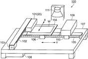
우선, 본 실시예에 따른 액적 토출 장치의 구성에 대하여, 도 1 내지 도 3을 참조하여 설명한다. 도 1은 액적 토출 장치의 구성을 나타내는 개략 사시도이다. 도 1에 나타내는 바와 같이, 액적 토출 장치(100)는 피토출물로서의 워크피스(W) 상에 액상체를 액적으로서 토출하여, 액상체로 이루어지는 막을 형성하는 것이다. 워크피스(W)가 탑재되는 스테이지(104)와, 탑재된 워크피스(W)에 액상체를 액적으로서 토출하는 복수의 액적 토출 헤드(20)(도 2 참조)가 탑재된 헤드 유닛(101)을 구비하고 있다.First, the configuration of the droplet ejection apparatus according to the present embodiment will be described with reference to FIGS. 1 to 3. 1 is a schematic perspective view showing the configuration of a droplet ejection apparatus. As shown in FIG. 1, the
그리고, 헤드 유닛(101)을 부주사 방향(X 방향)으로 구동하기 위한 X 방향 가이드 축(102)과, X 방향 가이드 축(102)을 회전시키는 X 방향 구동 모터(103)를 구비하고 있다. 또한, 스테이지(104)를 부주사 방향에 대하여 직교하는 주주사 방향(Y방향)으로 가이드하기 위한 Y방향 가이드 축(105)과, Y방향 가이드 축(105)에 걸어맞춰 회전하는 Y방향 구동 모터(106)를 구비하고 있다. 이들 X 방향 가이드 축(102)과 Y방향 가이드 축(105)이 상부에 마련된 기대(107)를 갖고, 그 기대(107)의 하부에, 제어 장치(108)를 구비하고 있다.And the X direction guide
또한, 헤드 유닛(101)의 복수의 액적 토출 헤드(20)를 클리닝(회복 처리)하기 위해, Y방향 가이드 축(105)을 따라 이동하는 클리닝 기구(109)와, 토출된 액상체를 가열하여 용매를 증발·건조시키기 위한 히터(111)를 구비하고 있다. 클리닝 기구(109)는 Y방향 가이드 축(105)에 걸어맞춰 회전하는 Y방향 구동 모터(110)를 갖고 있다.In addition, in order to clean (recover) the plurality of droplet ejection heads 20 of the
헤드 유닛(101)에는, 액상체를 워크피스(W)에 도포하는 복수의 액적 토출 헤드(20)(도 2 참조)를 구비하고 있다. 그리고, 이들 복수의 액적 토출 헤드(20)에 의해, 제어 장치(108)로부터 공급되는 토출용 제어 신호에 따라, 개별적으로 액상체를 토출할 수 있게 되어 있다. 이 액적 토출 헤드(20)에 대해서는 후술한다.The
X 방향 구동 모터(103)는 이것에 한정되는 것은 아니지만, 예컨대, 스테핑 모터 등이며, 제어 장치(108)로부터 구동 펄스 신호가 공급되면, X 방향 가이드 축(102)을 회전시켜, X 방향 가이드 축(102)에 걸어 맞춘 헤드 유닛(101)을 X 방향으로 이동시킨다.Although the X direction drive
마찬가지로 Y방향 구동 모터(106, 110)는 이것에 한정되는 것은 아니지만, 예컨대, 스테핑 모터 등이며, 제어 장치(108)로부터 구동 펄스 신호가 공급되면, Y방향 가이드 축(105)에 걸어 맞춰 회전하고, Y방향 구동 모터(106, 110)를 구비한 스테이지(104) 및 클리닝 기구(109)를 Y방향으로 이동시킨다.Similarly, the Y-
클리닝 기구(109)는 액적 토출 헤드(20)를 클리닝할 때에는, 헤드 유닛(101)을 면하는 위치로 이동하고, 액적 토출 헤드(20)의 노즐면에 밀착하여 불필요한 액상체를 흡인하는 캐핑(capping), 액상체 등이 부착된 노즐면을 닦아내는 와이핑(wipping), 액적 토출 헤드(20)의 전체 노즐로부터 액상체를 토출하는 예비 토출 또는 불필요하게 된 액상체를 받아 배출시키는 처리를 행한다. 클리닝 기구(109)의 상세에 대해서는 생략한다.When the
히터(111)는 이것에 한정되는 것은 아니지만, 예컨대, 램프 어닐링에 의해 워크피스(W)를 열처리하는 수단이며, 워크피스(W) 상에 토출된 액상체를 가열하여, 용매를 증발시켜 막으로 변환하기 위한 열처리를 행한다. 이 히터(111)의 전원의 투입 및 차단도 제어 장치(108)에 의해 제어된다.The
액적 토출 장치(100)의 도포 동작은 제어 장치(108)로부터 소정의 구동 펄스 신호를 X 방향 구동 모터(103) 및 Y방향 구동 모터(106)로 보내어, 헤드 유닛(101)을 부주사 방향(X 방향)으로, 스테이지(104)를 주주사 방향(Y방향)으로 상대 이동 시킨다. 그리고, 이 상대 이동 동안에 제어 장치(108)로부터 토출용 제어 신호를 공급하고, 각 액적 토출 헤드(20)로부터 워크피스(W)의 소정 영역에 액상체를 액적으로서 토출하여 도포를 행한다.The application operation of the
도 2는 액적 토출 헤드의 구조를 나타내는 개략도이다. 동도 (a)는 액적 토출 헤드의 구조를 나타내는 개략 사시도, 동도 (b)는 액적 토출 헤드의 복수 노즐의 배치를 나타내는 개략 평면도이다. 한편, 동도는 구성을 명확히 하기 위해 적절히 확대 또는 축소하고 있다.2 is a schematic view showing the structure of a droplet ejection head. (A) is a schematic perspective view which shows the structure of a droplet discharge head, and FIG. (B) is a schematic plan view which shows arrangement | positioning of the some nozzle of a droplet discharge head. On the other hand, the same is expanded or reduced appropriately to clarify the configuration.
도 2(a)에 나타내는 바와 같이, 액적 토출 헤드(20)는 복수의 노즐(22)을 갖는 노즐 플레이트(21)와 각 노즐(22)에 대응하여 이것을 구획하는 구획부(24)를 포함하는 액상체의 유로가 형성된 레저버 플레이트(reservoir plate)(23)와, 에너지 발생 수단으로서의 압전 소자(피에조)(29)를 갖는 진동판(28)으로 이루어지는 3층 구조의 소위 피에조 방식 잉크젯 헤드이다. 노즐 플레이트(21)와 레저버 플레이트(23)의 구획부(24) 및 진동판(28)에 의해 복수의 압력 발생실(25)이 구성되어 있다. 각 노즐(22)은 각 압력 발생실(25)에 각각 연결되어 있다. 또한, 압전 소자(29)는 각 압력 발생실(25)에 대응하도록 진동판(28)에 복수 마련되어 있다.As shown in FIG. 2 (a), the
레저버 플레이트(23)에는, 진동판(28)에 형성된 공급 구멍(28a)을 통하여 탱크(도시하지 않음)로부터 공급되는 액상체가 일시적으로 저장되는 공통 유로(27)가 마련되어 있다. 또한 공통 유로(27)에 충전된 액상체는 공급구(26)를 통하여 각 압력 발생실(25)에 공급된다.The
도 2(b)에 나타내는 바와 같이, 액적 토출 헤드(20)는 2개의 노즐열(22a, 22b)을 갖고 있고, 각각 복수(180개)의 직경이 약 28㎛인 노즐(22)이 피치 P1로 배열되어 있다. 그리고, 2개의 노즐열(22a, 22b)은 서로 피치 P1에 대하여 반인 노즐 피치 P2 어긋난 상태로 노즐 플레이트(21)에 마련되어 있다. 이 경우, 피치 P1은 약 140㎛이다. 따라서, 노즐열(22a, 22b)에 직교하는 방향에서 보면 360개의 노즐(22)이 약 70㎛의 노즐 피치 P2로 배열된 상태로 되어 있다. 따라서, 2개의 노즐열(22a, 22b)을 갖는 액적 토출 헤드(20)의 유효 노즐의 전장은 노즐 피치 P2×359(약 25㎜)이다. 또한, 노즐열(22a, 22b)의 간격은 약 2.54㎜이다.As shown in Fig. 2 (b), the
액적 토출 헤드(20)는 전기 신호로서의 구동 파형이 압전 소자(29)에 인가되면 압전 소자(29) 자체가 비뚤어져 진동판(28)을 변형시킨다. 이것에 의해, 압력 발생실(25)의 부피 변동이 일어나, 이것에 의한 펌프 작용으로 압력 발생실(25)에 충전된 액상체가 가압되어, 노즐(22)로부터 액상체가 액적(30)으로서 토출될 수 있다.When the drive waveform as an electrical signal is applied to the
한편, 본 실시예의 액적 토출 헤드(20)는, 소위 2열의 노즐열(22a, 22b)을 갖고 있지만, 이것에 한정되지 않고 1열이라도 좋다. 그 위에, 노즐(22)로부터 액상체를 액적(30)으로서 토출시키는 에너지 발생 수단은 압전 소자(29)에 한정되지 않고, 전기 열변환 소자로서의 히터나 전기 기계 변환 소자로서의 정전 액츄에이터 등이라도 좋다.On the other hand, the
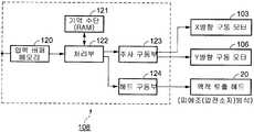
도 3은 제어 장치 및 제어 장치에 관련되는 각 부와의 전기적인 구성을 나타 내는 블록도이다. 도 3에 나타내는 바와 같이, 제어 장치(108)는 액상체의 토출 데이터를 외부 정보 처리 장치로부터 수취하는 입력 버퍼 메모리(120)와, 입력 버퍼 메모리(120)에 일시적으로 기억된 토출 데이터를 기억 수단(RAM)(121)에 전개하여 관련되는 각 부에 제어 신호를 보내는 처리부(122)를 구비하고 있다. 또한, 처리부(122)로부터의 제어 신호를 받아 X 방향 구동 모터(103)와 Y방향 구동 모터(106)에 위치 제어 신호를 보내는 주사 구동부(123)와, 마찬가지로 처리부(122)로부터의 제어 신호를 받아 액적 토출 헤드(20)에 구동 전압 펄스(구동 파형)를 보내는 헤드 구동부(124)를 구비하고 있다.3 is a block diagram showing the electrical configuration of the controller and the respective parts related to the controller. As shown in FIG. 3, the
입력 버퍼 메모리(120)에 수취되는 토출 데이터는 워크피스(W) 상의 막 형성 영역의 상대 위치를 나타내는 데이터와, 막 형성 영역에 액상체의 액적을 도트로서 어떻게 배치하는가를 나타내는 데이터와, 액적 토출 헤드(20)의 노즐열(22a, 22b) 중, 어떤 노즐(22)을 구동(ON-OFF)할지를 지정하는 데이터를 포함하고 있다.The discharge data received by the
처리부(122)는 기억 수단으로서의 RAM(121)에 저장된 토출 데이터 중에서 막 형성 영역에 관한 위치의 제어 신호를 주사 구동부(123)로 보낸다. 주사 구동부(123)는 이 제어 신호를 받아 X 방향 구동 모터(103)에 위치 제어 신호를 보내어 액적 토출 헤드(20)를 부주사 방향(X 방향)으로 이동시킨다. 또한 Y방향 구동 모터(106)에 위치 제어 신호를 보내어 워크피스(W)가 유지된 스테이지(104)를 주주사 방향(Y방향)으로 이동시킨다. 이것에 의해 워크피스(W)의 소망의 위치에 액적 토출 헤드(20)로부터 액상체의 액적(30)이 토출되도록 액적 토출 헤드(20)와 워크피스(W)를 상대 이동시킨다.The
또 처리부(122)는 RAM(121)에 저장된 토출 데이터 중에서 막 형성 영역에 액상체의 액적(30)을 도트로서 어떻게 배치하는지를 나타내는 데이터를, 노즐(22)마다의 4bit의 토출 비트맵 데이터로 변환하여 헤드 구동부(124)로 보낸다. 또한, 액적 토출 헤드(20)의 노즐열(22a, 22b) 중, 어떤 노즐(22)을 구동(ON-OFF)할지를 지정하는 데이터에 근거하여, 액적 토출 헤드(20)의 압전 소자(29)에 인가하는 구동 전압 펄스(구동 파형)를 언제 발신하는지의 「타이밍 검출 신호」인 래치(LAT) 신호와 채널(CH) 신호를 헤드 구동부(124)로 보낸다. 헤드 구동부(124)는 이들 제어 신호를 받아 액적 토출 헤드(20)에 적정한 구동 전압 펄스(구동 파형)를 보내어, 노즐(22)로부터 액상체의 액적(30)을 토출시킨다.In addition, the
도 2에 나타낸 바와 같이, 각 노즐열(22a, 22b)은 각각 독립된 공통 유로(27)에 연결되어 있다. 따라서, 각 노즐열(22a, 22b)을 구성하는 각각 180개의 노즐(22)의 압전 소자(29)에 동시에 구동 파형을 인가하면, 이웃하는 노즐(22) 사이에서, 액적의 토출량(부피 또는 중량)이나 토출 속도가 변동하는 전기적, 기계적인 크로스 토크가 생기기 쉽다.As shown in FIG. 2, each
그러므로, 본 실시예에서는, 처리부(122)는 막 형성 영역에 걸친 이웃하는 노즐(22)로부터는 동시에 액적을 토출하지 않도록 헤드 구동부(124)에 LAT 신호와 CH 신호를 보낸다. 구체적으로는, 헤드 구동부(124)는 LAT 신호에 대응하여 소정 주기로 구동 전압 펄스(구동 파형)를 발생시킨다. 그리고, 처리부(122)는 워크피스(W)와 액적 토출 헤드(20)의 상대 이동에 동기하여, 시계열적으로 다른 구동 파형이 상기 이웃하는 노즐(22)에 대응하는 압전 소자(29)에 인가되도록, CH 신호를 헤드 구동부(124)로 보낸다. 또한, 주주사에 있어서, 구동 파형이 인가되는 압전 소자(29)의 수가 구동 파형마다 동수로 되도록, 막 형성 영역에 걸친 이웃하는 노즐(22)에 인가하는 서로 다른 토출 타이밍의 구동 파형의 조합을 설정하고 있다. 상세하게는, 후술하는 액상체의 도출 방법에서 설명한다. 이것에 의해 적어도 전기적인 크로스 토크를 회피함과 아울러, 전기적인 부하에 의한 구동 파형마다의 꺽임을 균일화하여, 안정한 토출량으로 액적을 토출하는 것을 실현하고 있다.Therefore, in the present embodiment, the
<컬러 필터><Color filter>
다음에 본 실시예에 따른 컬러 필터에 대하여 설명한다. 도 4는 컬러 필터를 나타내는 평면도이다.Next, a color filter according to the present embodiment will be described. 4 is a plan view illustrating a color filter.
도 4에 나타내는 바와 같이, 컬러 필터(10)는 투명한 기판으로서의 유리 기판(1)의 표면에 복수의 막 형성 영역(2)을 구획하는 격벽부(4)를 갖고 있다. 환언하면, 격벽부(4)는, 복수의 막 형성 영역(2)을 구획하는 구획 영역을 구성하고 있다. 각 막 형성 영역(2)에는, 3색(R;적색, G;녹색, B; 청색)의 착색층(3)이 형성되어 있다. 각 착색층(3R, 3G, 3B)은 동색의 착색층(3)끼리가 직선적으로 배치되어 있다. 즉, 컬러 필터(10)는 스트라이프 방식의 착색층(3)을 구비하고 있다.As shown in FIG. 4, the
<컬러 필터의 제조 방법><Method of manufacturing color filter>
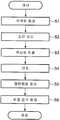
다음에 본 실시예의 컬러 필터의 제조 방법에 대하여 도 5 및 도 6을 참조하여 설명한다. 도 5는 컬러 필터의 제조 방법을 나타내는 흐름도, 도 6(a) 내지 도 6(f)는 컬러 필터의 제조 방법을 나타내는 개략 단면도이다. 또한, 본 실시예의 컬러 필터(10)의 제조 방법은 상술한 액적 토출 장치(100)와 후술하는 액상체의 토출 방법을 이용한 것이다.Next, the manufacturing method of the color filter of a present Example is demonstrated with reference to FIG. 5 is a flowchart showing a method for manufacturing a color filter, and FIGS. 6 (a) to 6 (f) are schematic cross-sectional views showing a method for manufacturing a color filter. In addition, the manufacturing method of the
도 5에 나타내는 바와 같이, 본 실시예의 컬러 필터(10)의 제조 방법은 유리 기판(1)에 격벽부(4)를 형성하는 공정(단계 S1)과, 격벽부(4)가 형성된 유리 기판(1)의 표면을 처리하는 공정(단계 S2)을 구비하고 있다. 그리고, 표면 처리된 유리 기판(1)에 기능성 재료로서의 착색 재료를 포함하는 3색의 액상체를 토출하는 공정(단계 S3)과, 토출된 액상체를 건조하고 고화해서 착색층(3)을 형성하는 공정(단계 S4)을 구비하고 있다. 또한, 형성된 격벽부(4)와 착색층(3)을 덮도록 평탄화층을 형성하는 공정(단계 S5)과, 평탄화층 상에 투명 전극을 형성하는 공정(단계 S6)을 구비하고 있다.As shown in FIG. 5, the manufacturing method of the
도 5의 단계 S1은 격벽부 형성 공정이다. 단계 S1에서는, 도 6(a)에 나타내는 바와 같이, 우선, 유리 기판(1)의 표면에, 막 형성 영역(2)을 구획하도록 제 1 격벽부(4a)를 형성한다. 형성 방법으로는, 진공 증착법이나 스퍼터법에 의해, Cr이나 Al 등의 금속막 또는 금속 화합물의 막을 유리 기판(1)의 표면에 차광성을 갖도록 성막한다. 그리고 포토리소그라피법에 의해, 감광성 수지(포토레지스트)를 도포하여 막 형성 영역(2)이 개구하도록 노광·현상·에칭한다. 계속해서 포토리소그라피법에 의해, 감광성의 격벽부 형성 재료를 약 2㎛의 두께로 도포하여 노광·현상하고, 제 2 격벽부(4b)를 제 1 격벽부(4a) 상에 형성한다. 격벽부(4)는 제 1 격벽부(4a)와 제 2 격벽부(4b)로 이루어지는 소위 2층 뱅크 구조로 되어 있다. 또, 격벽부(4)는 이것에 한정되지 않고, 차광성을 갖는 감광성의 격벽부 형성 재료를 이용하여 형성한 제 2 격벽부(4b)만의 일층 구조로 하여도 좋다. 그리고, 단계 S2로 진행한다.Step S1 of FIG. 5 is a partition wall forming process. In Step S1, as shown in FIG. 6A, first, the first
도 5의 단계 S2는 표면 처리 공정이다. 단계 S2에서는, 이후의 액상체의 토출 공정에서, 토출된 액상체가 막 형성 영역(2)에 탄착되어 스며들어 퍼지도록 유리 기판(1)의 표면을 친액 처리한다. 또한, 토출된 액상체의 일부가 제 2 격벽부(4b)에 탄착되었다고 해도 막 형성 영역(2) 내에 들어가도록 제 2 격벽부(4b)의 적어도 정부를 발액 처리한다.Step S2 of FIG. 5 is a surface treatment process. In step S2, in the subsequent discharging step of the liquid body, the surface of the
표면 처리 방법으로는 격벽부(4)가 형성된 유리 기판(1)에 대하여, O2를 처리 가스로 하는 플라즈마 처리와 불소계 가스를 처리 가스로 하는 플라즈마 처리를 행한다. 즉, 막 형성 영역(2)이 친액 처리되고, 그 후 감광성 수지로 이루어지는 제 2 격벽부(4b)의 표면(벽면을 포함함)이 발액 처리된다. 한편, 제 2 격벽부(4b)를 형성하는 재료 자체가 발액성을 갖고 있으면 후자의 처리를 생략하는 할 수도 있다. 그리고, 단계 S3으로 진행한다.Surface treatment methods include a plasma treatment is carried out to the plasma treatment with fluorine gas a, O2 with respect to the
도 5의 단계 S3은 액상체의 토출 공정이다. 단계 S3에서는, 도 6(b)에 나타내는 바와 같이, 액적 토출 장치(100)의 스테이지(104)에 표면 처리된 유리 기판(1)을 탑재한다. 그리고, 유리 기판(1)이 탑재된 스테이지(104)와 액적 토출 헤드(20)의 주주사 방향으로의 상대 이동에 동기하여, 착색 재료를 포함하는 액상체가 충전된 액적 토출 헤드(20)의 복수의 노즐(22)로부터 액적(30)을 막 형성 영 역(2)에 토출한다. 막 형성 영역(2)에 토출되는 액상체의 총 토출량은 이후의 건조 공정(단계 S4)에서 소정의 막 두께가 얻어지도록, 미리 토출 회수 등이 설정된 토출 데이터에 근거해서, 제어 장치(108)의 처리부(122)로부터 적정한 제어 신호가 헤드 구동부(124)로 보내져 제어된다. 자세한 액상체의 토출 방법은 후술한다. 그리고, 단계 S4로 진행한다.Step S3 of FIG. 5 is a discharging process of the liquid body. In step S3, as shown in FIG. 6B, the
도 5의 단계 S4는 건조 공정이다. 단계 S4에서는, 도 6(c)에 나타내는 바와 같이, 액적 토출 장치(100)에 구비된 히터(111)에 의해 유리 기판(1)이 가열되고, 토출된 액상체로부터 용매 성분이 증발하여 고화되고, 착색 재료로 이루어지는 착색층(3)이 형성된다. 그리고, 단계 S5로 진행된다.Step S4 of FIG. 5 is a drying process. In step S4, as shown in FIG. 6C, the
도 5의 단계 S5는 평탄화층 형성 공정이다. 단계 S5에서는, 도 6(e)에 나타내는 바와 같이, 착색층(3)과 제 2 격벽부(4b)를 덮도록 평탄화층(6)을 형성한다. 형성 방법으로는, 스핀 코팅법, 롤코팅법 등에 의해 아크릴계 수지를 코팅하여 건조시키는 방법을 들 수 있다. 또한, 감광성 아크릴 수지를 코팅하고 나서 자외광을 조사하여 경화시키는 방법도 채용할 수 있다. 막 두께는 약 100㎚이다. 한편, 착색층(3)이 형성된 유리 기판(1)의 표면이 비교적 평탄하면, 평탄화층 형성 공정을 생략하여도 좋다. 그리고, 단계 S6으로 진행한다.Step S5 of FIG. 5 is a planarization layer forming process. In step S5, as shown to FIG. 6 (e), the
도 5의 스텝 S6은 투명 전극 형성 공정이다. 단계 S6에서는, 도 6(f)에 나타내는 바와 같이, 평탄화층(6) 위에 ITO(Indium Tin Oxide) 등으로 이루어지는 투명 전극(7)을 성막한다. 성막 방법으로는, ITO 등의 도전 재료를 타깃으로 하여 진공 중에서 증착 또는 스퍼터링하는 방법을 들 수 있다. 막 두께는 약 10㎚이다. 형성된 투명 전극(7)은 컬러 필터(10)가 사용되는 전기 광학 장치에 의해 적절히 필요한 형상(패턴)으로 가공된다.Step S6 of FIG. 5 is a transparent electrode formation process. In step S6, as shown in FIG. 6F, a
본 실시예에서는, 우선 R(적색)의 착색 재료를 포함하는 액상체를 막 형성 영역(2)으로 토출하여 건조시키는 것에 의해 착색층(3R)을 형성하고, 계속해서 G(녹색), B(청색)의 순서로 다른 착색 재료를 포함하는 액상체를 순차 토출하여 건조함으로써, 도 6(d)에 나타내는 바와 같이, 3색의 착색층(3R, 3G, 3B)을 형성했다. 한편, 이것에 한정되지 않고, 예컨대, 단계 S3의 액상체의 토출 공정에서 다른 착색 재료를 포함하는 3색의 액상체를 각각 다른 액적 토출 헤드(20)에 충전하고, 각 액적 토출 헤드(20)를 헤드 유닛(101)에 장착하여, 각 액적 토출 헤드(20)로부터 소망의 막 형성 영역(2)으로 액상체를 토출한다. 그리고, 용매의 증기압을 일정하게 하여 건조하는 것이 가능한 감압 건조 장치에 유리 기판(1)을 세팅하여 감압 건조하는 방법을 사용할 수도 있다.In the present embodiment, first, the liquid layer containing the coloring material of R (red) is discharged into the
<액상체의 토출 방법><Discharge Method of Liquid Body>
본 실시예의 액상체의 토출 방법에 대하여 실시예에 근거하여, 더욱 자세히 설명한다.The discharge method of the liquid body of the present embodiment will be described in more detail based on the examples.
우선, 본 실시예에 따른 구동 파형에 대하여 도 7을 참조하여 설명한다. 도 7은 구동 파형과 제어 신호의 관계를 나타내는 타이밍 차트이다.First, the driving waveform according to the present embodiment will be described with reference to FIG. 7 is a timing chart showing a relationship between a drive waveform and a control signal.
도 7에 나타내는 바와 같이, 각 노즐(22)에 대응하여 마련된 압전 소자(29)(도 2 참조)에는, 제어 신호 LAT의 타이밍에서 래치된 노즐(22)마다의 ON/OFF 데이터(토출 데이터)에 따라, 구동 파형 A1, B1, C1, A2, B2, C2, …의 일부가 선택되어 공급된다. 그리고, 구동 파형이 공급되는 타이밍에, 노즐(22)로부터 액적(30)이 토출된다. 또, 각 구동 파형은 압전 소자(29)에 공급되는 것에 의해 규정량의 액적(30)이 토출되도록 설계된 동일 형상, 크기의 것이다.As shown in FIG. 7, the piezoelectric element 29 (see FIG. 2) provided corresponding to each
구동 파형의 선택은 구동 파형의 공급 타이밍을 규정하는 제어 신호 CH1 내지 CH3에 의해 실시된다. 즉, 제어 신호 CH1에 의해 제 1 계통의 타이밍의 구동 파형 A1, A2, …가, 제어 신호 CH2에 의해 제 2 계통의 타이밍의 구동 파형 B1, B2, …가 제어 신호 CH3에 의해 제 3 계통의 타이밍의 구동 파형 C1, C2, …가 각각 선택된다.Selection of the drive waveform is performed by control signals CH1 to CH3 that define the timing of supply of the drive waveform. That is, the drive waveforms A1, A2,... Of the timing of the first system are controlled by the control signal CH1. The driving waveforms B1, B2,... Drive waveforms C1, C2,... Are selected respectively.
본 실시예에서는, 막 형성 영역(2)에 걸친 이웃하는 노즐(22)에 대응하는 압전 소자(29)에, 구동 파형의 공급 타이밍의 계통(제어 신호 LAT를 기준으로 한 상대적인 서열)을 개개에 대응시키는 것에 의해, 토출 타이밍의 중복이 일어나지 않도록 되어 있다. 이것에 의해, 적어도 전기적인 크로스 토크가 적합하게 감소되어, 크로스 토크에 기인하는 노즐간의 토출 특성(토출량이나 토출 속도 등)의 편차가 상대적으로 완화되어 있다. 또한, 각 계통의 타이밍은 주기적으로 되어있기 때문에, 토출 조건이 각 토출 타이밍 동안에 일정하게 되어, 액적(30)의 토출량을 주주사 방향에 대하여 안정화시킬 수 있다. 또한, 제어 신호 LAT의 1주기(1래치) 내에 있어서, 3개의 구동 파형이 발생하므로, 동일한 압전 소자(29)에 1래치 내에서 3개의 구동 파형을 인가하면, 동일 노즐(22)로부터 토출 타이밍을 변경하여 3 방울의 액적(30)을 토출할 수 있다. 또한, 1래치 내의 3개의 구동 파형을 각각 별도의 압전 소자(29)에 인가하면, 3개의 노즐(22)로부터 액적(30)을 다른 토출 타이밍에서 토출할 수 있다. 이후, 노즐(22)의 압전 소자(29)에 구동 파형을 인가하는 것을 노즐(22)에 구동 파형을 인가한다고 표현한다.In this embodiment, the
액적 토출 장치(100)에 있어서, 예컨대, 액적 토출 헤드(20)(복수의 노즐(22))와 유리 기판(1)의 주주사에 있어서의 상대 이동 속도를 200㎜/초로 한다. 또한, 제어 신호 LAT의 주기, 즉 구동 주파수를 20㎑로 한다. 이 토출 조건에서는, 주주사에서 1회의 토출에 따른 토출 분해능은 1래치를 기준으로 하여 3개의 구동 파형 중 하나를 사용하는 노즐(22)에 인가하면, 약 10㎛로 된다. 환언하면, 3개의 구동 파형을 연속적으로 사용하는 노즐(22)에 인가했을 때에는, 토출 타이밍을 변경하여 주주사 방향에 약 3.3㎛의 최소 피치로 액적을 토출하는 것이 가능하다.In the
(실시예 1)(Example 1)
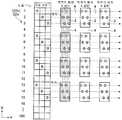
도 8은 실시예 1의 액상체의 토출 방법을 나타내는 개략도이다. 자세하게는, 노즐열에서의 구동 파형의 선택과 막 형성 영역에서의 액적의 배치를 나타내는 개략도이다.8 is a schematic view showing a method of discharging a liquid body of Example 1; In detail, it is a schematic diagram which shows selection of the drive waveform in a nozzle row, and arrangement | positioning of the droplet in a film formation area.
도 8에 나타내는 바와 같이, 노즐열(22a)의 180개의 노즐(22)에 노즐 번호가 부여되고 있다. 또한, 각 노즐(22)에 인가하는 구동 파형의 파형 선택의 방법이 예시되어 있다. 파형 선택에 있어서의 번호 1은 도 7의 제 1 계통의 타이밍에서 발생하는 구동 파형 A1, A2, …를 가리킨다. 마찬가지로, 번호 2는 제 2 계통의 타이밍에서 발생하는 구동 파형 B1, B2, …를 가리키고, 번호 3은 제 3 계통의 타이밍에 발생하는 구동 파형 C1, C2, …을 가리킨다. 이하, 그림에서 ○표의 번호 1 내지 3을 파형 선택의 계통 번호 1 내지 3이라 한다.As shown in FIG. 8, the nozzle number is attached to 180
막 형성 영역(2)의 크기나 X 방향 및 Y방향에서의 배치 피치는, 설계 사항이지만, 실시예 1에서는, 노즐(22)의 배치 피치(약 140㎛)에 대하여 1회의 주주사로 2개의 노즐(22)이 각각의 막 형성 영역(2)에 걸친 상태로 되어 있다. 환언하면, 도 4에 나타내는 컬러 필터(10)의 스트라이프 방향과 노즐열 방향이 일치하도록, 액적 토출 헤드(20)와 유리 기판(1)이 상대 배치되어 있다.Although the size of the
주주사에 있어서, 막 형성 영역(2)을 구획하는 격벽부(4)를 통과하는 노즐(22) 및 토출된 액적의 적어도 일부가 격벽부(4)에 착탄한다고 상정되는 노즐(22)은 사용하지 않는다. 즉, 비토출로 하고 있다. 그리고, 각 막 형성 영역(2)에서 이웃하는 노즐(22)(사용 노즐)로부터 주주사 방향에 각각 2방울의 액적을 토출한다. 막 형성 영역(2)에서 X 방향으로 그어진 쇄선은 제 1 내지 제 3 계통의 구동 파형을 인가했을 때의 액적의 주주사 방향(Y방향)의 위치를 나타내는 것이다. 한편, 도 8은 동종의 액상체가 토출되는 막 형성 영역(2)에 대하여, 선택 파형의 조합과 이것에 대한 액적의 배치 패턴을 나타내는 것이다.In the main scanning, the
실시예 1의 액상체의 토출 방법은, 도 8에 나타낸 노즐열(22a)에서의 파형 선택을 전제로 한다. 즉, 막 형성 영역(2)에 걸친 이웃하는 노즐(22)에, 동일 타이밍으로 구동 파형이 인가되지 않도록, 제 1 내지 제 3 계통의 구동 파형을 차차 선택하여 인가한다.The discharge method of the liquid body of Example 1 presupposes waveform selection in the
파형 선택 1은, 180개의 노즐(22)에 대하여, 노즐 번호 1 내지 180의 순서로, 계통 번호 1 내지 3을 반복하여 할당하고 있다. 단, 불토출로 한 노즐(22)에는, 구동 파형의 계통을 할당하지 않고 있다. 예컨대, 동 도면에서는, 노즐 번호4, 8, 12, 16을 불토출로 하고, 계통 번호를 할당하고 있지 않다. 즉, 사용하는 노즐(22)(이하, 사용 노즐이라 한다)에만 계통 번호를 할당하고 있다. 이와 같이 할당함으로써 토출 데이타 생성시의 부하를 경감하고 있다.
파형 선택 1을 적용하면, 예컨대, 노즐 번호 1의 노즐(22)에는, 제 1 계통의 구동 파형 A1, A2가 인가된다. 노즐 번호 2의 노즐(22)에는, 제 2 계통의 구동 파형 B1, B2가 인가된다. 노즐 번호 3의 노즐(22)에는, 제 3 계통의 구동 파형 C1, C2이 인가된다. 이것에 의해, 노즐 번호 1, 2, 3의 각 노즐(22)로부터 막 형성 영역(2)에 토출된 액적의 배치는, A 패턴과 같이 6개의 액적이 서로 주주사 방향으로 어긋난다. 주주사 방향(Y 방향)으로 배열한 막 형성 영역(2)에는, 동일 파형 선택1이 적용되고, 반복 A 패턴과 같이 액적이 배치된다. 따라서, 동종의 액상체가 토출되는 막 형성 영역(2)에 걸친 이웃하는 3개의 노즐(22)에는, 각각 토출 타이밍이 다른 구동 파형이 인가되어, 노즐사이의 전기적인 크로스 토크가 회피된다. 또한, 제어 신호 LAT의 1 래치에 있어서, 사용 노즐의 수가 구동 파형마다 동수로 되기 때문에, 구동 파형마다의 전기적인 부하가 평준화되어, 구동 파형마다의 꺽임이 균일화된다. 따라서, 소망의 막 형성 영역(2)에 안정한 토출량으로 액상체가 토출된다. 또한, 막 형성 영역(2)마다 액적의 배치가 동일하게 된다. 환언하면, 각 막 형성 영역(2)에 있어서의 액적의 배치가 균질화된다.When
(실시예 2)(Example 2)
다음에 실시예 2의 액상체의 토출 방법에 대하여, 실시예 1과의 상위점을 중심으로 설명한다. 도 9는 실시예 2의 액상체의 토출 방법을 나타내는 개략도이다.Next, the discharge method of the liquid body of Example 2 is demonstrated centering on difference with Example 1. FIG. 9 is a schematic view showing a method of discharging a liquid body of Example 2;
도 9에 나타내는 바와 같이, 실시예 2의 액상체의 토출 방법은 실시예 1에 대하여 파형 선택 1에 있어서의 노즐 번호에의 제 1 내지 제 3 계통의 구동 파형의 할당이 다르다. 구체적으로는, 노즐열(22a)에서의 구동 파형의 계통의 나열 순서를 말하면, 계통 번호 1, 2, 3, 2, 3, 1, 3, 1, 2, …(이하 그 반복)으로 되어 있다. 이러한 파형 선택에 의해, 이웃하는 노즐(22)에는, 같은 계통의 구동 파형이 인가되지 않는다. 또한, 같은 계통의 구동 파형이 인가되는 노즐(22)의 수(사용하는 노즐(22)의 수)가 각 계통에서 거의 같게 되도록 설정되어 있다. 이것에 의해, 액적 토출 시의 각 구동 파형의 꺽임 쪽을 거의 균일화하여, 구동 파형의 꺽임에 의한 액적의 토출량의 치우침을 억제하고 있다. 다른 토출 조건(파형 선택의 방법)은 실시예 1과 마찬가지이다.As shown in FIG. 9, in the discharge method of the liquid body of Example 2, the assignment of the drive waveform of the 1st-3rd system to the nozzle number in
즉, 막 형성 영역(2)마다 파형 선택 1, 2, 3 중 어느 하나를 적용하므로, 액적의 배치는 D패턴, E패턴, F패턴의 어느 하나가 된다.That is, since any one of
(실시예 3)(Example 3)
다음에 실시예 3의 액상체의 토출 방법에 대하여, 실시예 2와의 상위점을 중심으로 설명한다. 도 10은 실시예 3의 액상체의 토출 방법을 나타내는 개략도이다.Next, the discharge method of the liquid body of Example 3 is demonstrated centering on difference with Example 2. As shown in FIG. 10 is a schematic view showing a method of discharging a liquid body of Example 3. FIG.
도 10에 나타내는 바와 같이, 실시예 3의 액상체의 토출 방법은 실시예 2에 대하여 파형 선택 1에 있어서의 노즐 번호에의 제 1 내지 제 3 계통의 구동 파형의 할당 방법은 동일하지만, 동일 노즐(22)로부터의 액적의 토출 시마다, 파형 선택 1 내지 6을 순차적으로 변경하고 있다. 파형 선택 2 내지 6은, 파형 선택 1에 대하여 제 1 내지 제 3 계통의 구동 파형의 선택을 1노즐씩 순차적으로 어긋나게 한 것이다. 따라서, 액적의 배치는 G패턴, H패턴, J패턴 중 어느 하나가 된다. 이것에 따르면, 막 형성 영역(2)에 걸친 이웃하는 노즐(22)에서, 액적의 토출 시마다 구동 파형의 계통이 변경된다. 환언하면, 동일 노즐(22)에서 액적의 토출 시마다 다른 구동 파형이 인가된다. 따라서, 각 막 형성 영역(2)에 배치되는 액적의 토출량의 치우침을 보다 분산시키고 있다.As shown in Fig. 10, in the method of discharging the liquid body of the third embodiment, the method of allocating the drive waveforms of the first to third systems to the nozzle number in the
(실시예 4)(Example 4)
다음에 실시예 4의 액상체의 토출 방법에 대하여, 실시예 1과의 상위점을 중심으로 설명한다. 도 11은 실시예 4의 액상체의 토출 방법을 나타내는 개략도이다.Next, the discharge method of the liquid body of Example 4 is demonstrated centering on difference with Example 1. FIG. 11 is a schematic view showing a method of discharging a liquid body of Example 4;
도 11에 나타낸 바와 같이, 실시예 4의 액상체의 토출 방법은, 실시예 1에 대하여 노즐열(22a)과 막 형성 영역(2)과의 상대적인 배치가 다르다. 실시예 4에서는, 동종의 액상체가 토출되는 막 형성 영역(2)이, 주주사 방향(Y 방향)으로 연속하여 배열되어 있다. 부주사 방향(X 방향)에는, 이종의 액상체가 토출되는 막 형성 영역(2)이 소정의 간격을 두고 배열되어 있다. 따라서, 1회의 토출에 따른 사용 노즐의 수는, 실시예 1에 비해 적어진다. 또한, 실시예 1와 같이 사용 노즐의 수가 구동 파형마다 동등하게 되도록 설정하고 있다. 따라서, 구동 파형마다의 토출에 의한 전기적인 부하가 더욱 작게 된다. 동종의 액상체가 토출되는 막 형성 영역(2)마다, 사용 노즐에 인가되는 다른 토출 타이밍의 구동 파형의 조합(파형 선택)을 다르게 한 점은, 실시예 2와 같다. 때문에, 액적의 배치는, G 패턴, H 패턴, J 패턴 중 어느 것으로 되고, 구동 파형의 꺽임에 의한 액적의 토출량의 기울기가 더욱 억제되어 있다. 한편, 실시예 4의 경우, 주주사에 있어서 직사각 형상의 막 형성 영역(2)의 긴 방향에 액적을 배치하므로, 막 형성 영역(2)마다 사용 노즐로부터 토출되는 액적의 수(토출수)는, 2 방울뿐만 아니라, 더욱 늘리더라도 좋다.As shown in FIG. 11, in the discharge method of the liquid body of Example 4, the relative arrangement | positioning of the
상기 실시예 1 내지 실시예 4에 있어서, 상술한 설명은 편의상 노즐열(22a)에만 착안한 것이었지만, 실제로는 노즐열(22a)의 피치를 보완하는 위치에서, 노즐열(22b)(도 2 참조)로부터도 마찬가지의 토출이 실시되게 되어 있다.In the first to fourth embodiments, the foregoing description focuses only on the
또, 막 형성 영역(2)에 부여되는 액상체의 총 토출량(필요량)은 요구되는 막의 특성(컬러 필터이면 투과율, 색도, 색상 등의 광학 특성)에 따라, 막 형성 영역(2)의 크기(면적)나, 액상체의 용질 농도를 고려하고 결정된다. 따라서, 상기 총 토출량을 복수회의 주주사에 의해 막 형성 영역(2)에 부여하는 경우에는, 주주사마다 상기 액적의 배치 패턴을 다르게 하는 것이 바람직하다. 즉, 주주사마다 파형 선택의 조합을 다르게 하는 것이 바람직하다. 이것에 따르면, 액적의 토출량의 치우침을 보다 분산시킬 수 있다.In addition, the total discharge amount (required amount) of the liquid to be applied to the
그 위에, 복수의 노즐(22)(액적 토출 헤드(20))을 부주사하여, 막 형성 영역(2)에 걸친 노즐(22)을 변경하여 주주사하면, 노즐간의 토출 특성 편차에 의한 액적의 토출량의 치우침를 더욱 분산시키는 것이 가능하다.When the plurality of nozzles 22 (droplet ejection heads 20) are sub-injected and the
이와 같이 막 형성 영역(2)에 걸친 이웃하는 노즐(22)에 인가하는 다른 토출 타이밍의 구동 파형의 조합을 변경하는 것은, 주주사마다 적어도 1회 행하는 것에 의해 상응의 작용과 효과를 얻을 수 있다.Changing the combination of the drive waveforms at different discharge timings applied to the neighboring
또, 상기 실시예 2 내지 실시예 4에 있어서, 파형 선택 1에 대하여 제 1 내지 제 3 계통의 구동 파형의 선택을 노즐열 방향에 1노즐씩 순차적으로 어긋나게 하여 다른 파형 선택을 설정하는 것은, 액적의 배치 패턴을 토출 데이터화할 때에, 파형 선택 1을 적용한 액적의 배치 패턴을 답습하면 바람직하기 때문에, 비교적 용이하게 할 수 있다.Further, in the second to fourth embodiments, the selection of the drive waveforms of the first to third systems with respect to the
<액정 표시 장치><Liquid crystal display device>
다음에 컬러 필터를 구비한 액정 표시 장치에 대하여, 간단히 설명한다. 도 12는 액정 표시 장치의 구성을 나타내는 개략 분해 사시도이다.Next, the liquid crystal display device provided with the color filter will be briefly described. 12 is a schematic exploded perspective view showing the configuration of a liquid crystal display device.
도 12에 나타내는 바와 같이, 액정 표시 장치(200)는 TFT(Thin Film Transistor) 투과형 액정 표시 패널(220)과, 액정 표시 패널(220)을 조명하는 조명 장치(216)를 구비하고 있다. 액정 표시 패널(220)은 컬러 필터를 갖는 대향 기판(201)과, 화소 전극(210)에 3단자 중 하나가 접속된 TFT 소자(211)를 갖는 소자 기판(208)과, 한 쌍의 기판(201, 208) 사이에 유지된 액정(도시하지 않음)을 구비 하고 있다. 또한, 액정 표시 패널(220)의 외면 측으로 되는 한 쌍의 기판(201, 208)의 표면에는, 투과하는 광을 편향시키는 상부 편광판(214)과 하부 편광판(215)이 마련된다.As shown in FIG. 12, the liquid
대향 기판(201)은 투명한 유리 등의 재료로 이루어지고, 액정을 사이에 유지하는 표면 측에 격벽부(204)에 의해 매트릭스 형상으로 구획된 복수의 막 형성 영역에, 적색(R), 녹색(G), 청색(B), 3색의 컬러 필터(205R, 205G, 205B)가 형성되어 있다. 격벽부(204)는 Cr 등의 차광성을 갖는 금속 또는 그 산화막으로 이루어지는 블랙 매트릭스라 불리는 하층 뱅크(202)와, 하층 뱅크(202)의 위(도면에서는 아래쪽)에 형성된 유기 화합물로 이루어지는 상층 뱅크(203)로 구성되어 있다. 또한, 격벽부(204)와 컬러 필터(205R, 205G, 205B)를 덮는 평탄화층으로서의 오버코팅층(OC층)(206)과, OC층(206)을 덮도록 형성된 ITO(Indium Tin Oxide) 등의 투명 도전막으로 이루어지는 대향 전극(207)을 구비하고 있다. 대향 기판(201)은 상기 실시예의 컬러 필터(10)의 제조 방법을 이용하여 제조되어 있다(실시예 1 내지 4의 어느 하나의 실시예를 적용).The opposing
소자 기판(208)은 마찬가지로 투명한 유리 등의 재료로 이루어지고, 액정을 사이에 유지하는 표면 측에 절연막(209)을 통해 매트릭스 형상으로 형성된 화소 전극(210)과, 화소 전극(210)에 대응하여 형성된 복수의 TFT 소자(211)를 갖고 있다. TFT 소자(211)의 3단자 중, 화소 전극(210)에 접속되지 않은 다른 2단자는 서로 절연된 상태로 화소 전극(210)을 둘러싸도록 격자 형상으로 마련된 주사선(212)과 데이터선(213)에 접속되어 있다.The
조명 장치(216)는, 예컨대, 광원으로서 백색의 LED, EL, 냉음극관 등을 이용하여, 이들 광원으로부터의 광을 액정 표시 패널(220)을 향하여 출사할 수 있는 도광판이나 확산판, 반사판 등의 구성을 구비한 것이면, 어떠한 것이라도 좋다.The
본 실시예의 액정 표시 장치(200)는, 상기 실시예의 컬러 필터(10)의 제조 방법을 이용하여 제조된 컬러 필터(205R, 205G, 205B)를 갖는 대향 기판(201)을 구비하고 있으므로, 색 불균일 등의 표시 불량이 적은 높은 표시 품질을 갖는다.Since the liquid
또한, 액정 표시 패널(220)은 액티브 소자로서 TFT 소자(211)에 한하지 않고 TFD(Thin Film Diode) 소자를 갖는 것이라도 좋고, 그 위에, 적어도 한편의 기판에 컬러 필터를 구비하는 것이면, 화소를 구성하는 전극이 서로 교차하도록 배치되는 패시브형의 액정 표시 장치라도 좋다. 또한, 상하 편광판(214, 215)은 시각 의존성을 개선할 목적 등으로 사용되는 위상차 필름 등의 광학 기능성 필름과 조합한 것이라도 좋다.In addition, the liquid
상기 실시예 1에 따르면, 이하의 효과가 얻어진다.According to the said Example 1, the following effects are acquired.
(1) 상기 실시예 1의 액상체의 토출 방법은, 막 형성 영역(2)에 걸친 사용 노즐에 다른 토출 타이밍의 구동 파형이 인가되어, 적어도 전기적인 크로스 토크가 저감된다. 또한, 각 계통의 구동 파형에 있어서, 사용 노즐의 수가 동등하게 되도록 설정되어 있다. 따라서, 구동 파형마다의 꺽임을 균일화하여, 액적의 토출량의 기울기를 억제할 수 있다. 따라서, 막 형성 영역에 안정한 토출량으로 액적을 토출할 수 있다. 즉, 막 형성 영역마다 필요량(총 토출량)의 액상체를 안정하게 부여할 수 있다.(1) In the method of discharging the liquid body of the first embodiment, drive waveforms at different discharge timings are applied to the use nozzles across the
(2) 상기 실시예 2의 액상체의 토출 방법은, 주주사 방향으로 배열하는 막 형성 영역(2)마다 적용하는 파형 선택을 바꾸기 때문에, 실시예 1의 효과에 더하여, 복수의 노즐(22)의 토출 특성 편차에 기인하는 액적의 토출량의 기울기가 억제되어, 주주사 방향의 줄무늬 형상의 토출 불균일을 저감할 수 있다.(2) Since the liquid discharge method of the second embodiment changes the waveform selection applied to each of the
(3) 상기 실시예 3의 액상체의 토출 방법은, 주주사 방향으로 배열하는 각 막 형성 영역(2)에 있어서, 액적의 토출마다 적용하는 파형 선택을 바꾸기 때문에, 상기 실시예 2의 효과에 더하여, 액적의 토출량의 기울기를 막 형성 영역(2)마다 억제하여, 주주사 방향의 줄무늬 형상의 토출 불균일을 보다 저감할 수 있다.(3) The method of discharging the liquid body of the third embodiment changes the waveform selection to be applied for each ejection of the droplet in each of the
(4) 상기 실시예 4의 액상체의 토출 방법은, 주주사 방향으로 연속적으로 배열한 동종의 액상체가 토출되는 막 형성 영역(2)마다, 다른 파형 선택을 적용하여 상기 막 형성 영역(2)에 걸리는 사용 노즐로부터 액적을 토출한다. 구동 파형마다 사용 노즐의 수가 동등하게 되도록 설정되고, 또한 실시예 1에 비교하여 동시에 구동 파형이 인가되는 사용 노즐의 수가 적어진다. 따라서, 실시예 1의 효과에 더하여, 액적의 토출에 따른 전기적인 부하가 더욱 작게 되어, 구동 파형의 꺽임에 의한 사용 노즐 사이의 액적의 토출량의 기울기를 더욱 억제할 수 있다.(4) In the method for discharging the liquid body of the fourth embodiment, a different waveform selection is applied to the
(5) 상기 실시예 1의 컬러 필터(10)의 제조 방법은, 상기 액상체의 토출 방법을 이용하여, 3색의 액상체를 각각 소망의 막 형성 영역(2)에 토출, 건조함으로써 착색층(3R, 3G, 3B)을 형성한다. 따라서, 각 막 형성 영역마다 필요량(총 토출량)의 액상체가 안정하게 부여되기 때문에, 토출 불균일에 의한 색불균일 등의 불량이 저감되어, 컬러 필터(10)를 수율 좋게 제조할 수 있다.(5) The manufacturing method of the
(실시예 2)(Example 2)
다음에 본 실시예에 따른 유기 EL(전기 발광) 소자를 구비한 유기 EL 표시 장치와, 유기 EL 소자의 제조 방법에 대하여 설명한다.Next, the organic electroluminescence display provided with the organic electroluminescent (electroluminescent) element which concerns on a present Example, and the manufacturing method of an organic electroluminescent element are demonstrated.
<유기 EL 표시 장치><Organic EL display device>
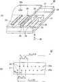
도 13은 유기 EL 표시 장치를 나타내는 개략 단면도이다. 도 13에 나타내는 바와 같이, 유기 EL 표시 장치(600)는 유기 EL 소자로서의 발광 소자부(603)를 갖는 소자 기판(601)과, 소자 기판(601)과 공간(622)을 사이를 두고 밀봉시킨 밀봉 기판(620)을 구비하고 있다. 소자 기판(601)은 기판 상에 회로 소자부(602)를 구비하고 있다. 발광 소자부(603)는 회로 소자부(602) 상에 중첩하여 형성되고, 회로 소자부(602)에 의해 구동되는 것이다. 발광 소자부(603)에는, 3색의 발광층(617R, 617G, 617B)이 각각 막 형성 영역으로서의 발광층 형성 영역(A)에 형성되고, 줄무늬 형상으로 되어 있다. 소자 기판(601)은 3색의 발광층(617R, 617G, 617B)에 대응하는 3개의 발광층 형성 영역(A)을 1조의 화소로 하고, 이 화소가 소자 기판(601)의 회로 소자부(602) 상에 매트릭스 형상으로 배치된 것이다. 유기 EL 표시 장치(600)는 발광 소자부(603)로부터의 발광이 소자 기판(601) 쪽으로 사출되는 것이다.13 is a schematic cross-sectional view illustrating an organic EL display device. As shown in FIG. 13, the
밀봉 기판(620)은 유리 또는 금속으로 이루어지는 것으로, 밀봉 수지를 통해 소자 기판(601)에 접합되어 있고, 밀봉된 안쪽 표면에는, 게터제(getter agent)(621)가 부착되어 있다. 게터제(621)는 소자 기판(601)과 밀봉 기판(620) 사이의 공간(622)에 침입한 물 또는 산소를 흡수하여, 발광 소자부(603)가 침입한 물 또는 산소에 의해 열화하는 것을 방지하는 것이다. 또, 이 게터제(621)는 생략하여도 좋다.The sealing
소자 기판(601)은 회로 소자부(602) 상에 복수의 발광층 형성 영역(A)을 갖는 것으로, 각 발광층 형성 영역(A)을 구획하는 격벽부(618)와, 각 발광층 형성 영역(A)에 형성된 전극(613)과, 전극(613)에 적층된 정공 주입/수송층(617a)를 구비하고 있다. 또한 복수의 발광층 형성 영역(A) 내에 발광층 형성 재료를 포함하는 3종의 액상체를 부여하여 형성된 발광층(617R, 617G, 617B)을 갖는 발광 소자부(603)를 구비하고 있다. 격벽부(618)는 하층 뱅크(618a)와 발광층 형성 영역(A)을 실질적으로 구획하는 상층 뱅크(618b)로 이루어지고, 하층 뱅크(618a)는 발광층 형성 영역(A)의 안쪽으로 연장하도록 마련되어, 전극(613)과 각 발광층(617R, 617G, 617B)이 직접 접촉하여 전기적으로 단락되는 것을 방지하기 위해 SiO2등의 무기 절연 재료에 의해 형성되어 있다.The
소자 기판(601)은, 예컨대, 유리 등의 투명한 기판으로 이루어지고, 소자 기판(601) 상에 실리콘산화막으로 이루어지는 베이스 보호막(606)이 형성되고, 이 베이스 보호막(606) 상에 다결정 실리콘으로 이루어지는 섬 형상의 반도체막(607)이 형성되어 있다. 한편, 반도체막(607)에는, 소스 영역(607a) 및 드레인 영역(607b)이 고농도 P 이온 투입에 의해 형성되어 있다. 또, P 이온이 도입되지 않은 부분이 채널 영역(607c)으로 되어 있다. 또한 베이스 보호막(606) 및 반도체막(607)을 덮는 투명한 게이트 절연막(608)이 형성되고, 게이트 절연막(608) 상에는 Al, Mo, Ta, Ti, W 등으로 이루어지는 게이트 전극(609)이 형성되고, 게이트 전극(609) 및 게이트 절연막(608) 상에는 투명한 제 1 층간 절연막(611a)과 제 2 층간 절연막(611b)이 형성되어 있다. 게이트 전극(609)은 반도체막(607)의 채널 영역(607c)에 대응하는 위치에 마련되어 있다. 또한, 제 1 층간 절연막(611a) 및 제 2 층간 절연막(611b)을 관통하여, 반도체막(607)의 소스 영역(607a), 드레인 영역(607b)에 각각 접속되는 콘택트 홀(612a, 612b)이 형성되어 있다. 그리고, 제 2 층간 절연막(611b) 상에, ITO(Indium Tin Oxide) 등으로 이루어지는 투명한 전극(613)이 소정 형상으로 패터닝되어 배치되고, 한편의 콘택트 홀(612a)이 이 전극(613)에 접속되어 있다. 또한, 또 하나의 콘택트 홀(612b)이 전원선(614)에 접속되어 있다. 이와 같이 하여, 회로 소자부(602)에는, 각 전극(613)에 접속된 구동용 박막 트랜지스터(615)가 형성되어 있다. 한편, 회로 소자부(602)에는, 보지 용량과 스위칭용 박막 트랜지스터도 형성되어 있지만, 도 13에서는 이들의 도시를 생략하고 있다.The
발광 소자부(603)는 양극으로서의 전극(613)과, 전극(613) 상에 순차 적층된 정공 주입/수송층(617a), 각 발광층(617R, 617G, 617B)(총칭하여 발광층(Lu))과, 상층 뱅크(618b)와 발광층(Lu)를 덮도록 적층된 음극(604)을 구비하고 있다. 정공 주입/수송층(617a)과 발광층(Lu)에 의해 발광이 여기되는 기능층(617)을 구성하고 있다. 한편, 음극(604)과 밀봉 기판(620) 및 게터제(621)를 투명한 재료로 구성하면, 밀봉 기판(620) 쪽으로부터 발광하는 광을 출사할 수 있다.The light emitting
유기 EL 표시 장치(600)는 게이트 전극(609)에 접속된 주사선(도시하지 않음)과 소스 영역(607a)에 접속된 신호선(도시하지 않음)을 갖고, 주사선에 전해진 주사 신호에 의해 스위칭용 박막 트랜지스터(도시하지 않음)가 온 상태로 되면, 그 때의 신호선의 전위가 보지 용량으로 보지되고, 상기 보지 용량의 상태에 따라, 구동용 박막 트랜지스터(615)의 온·오프 상태가 결정된다. 그리고, 구동용 박막 트랜지스터(615)의 채널 영역(607c)을 통해, 전원선(614)으로부터 전극(613)에 전류가 흐르고, 또한 정공 주입/수송층(617a)과 발광층(Lu)을 통해 음극(604)에 전류가 흐른다. 발광층(Lu)은 이것을 흐르는 전류량에 따라 발광한다. 유기 EL 표시 장치(600)는 이러한 발광 소자부(603)의 발광 메커니즘에 의해, 소망의 문자나 화상 등을 표시할 수 있다. 또한, 유기 EL 표시 장치(600)는 발광층(Lu)이 상기 실시예 1의 액상체의 토출 방법을 이용하여 형성되어 있기 때문에, 노즐열(22a, 22b)의 토출 특성 편차에 기인하는 발광 불균일, 휘도 불균일 등의 표시 불량이 감소되어, 높은 표시 품질을 갖고 있다.The organic
<유기 EL 소자의 제조 방법><Method for Manufacturing Organic EL Element>
다음에 본 실시예의 유기 EL 소자로서의 발광 소자부(603)의 제조 방법에 대하여 도 14를 참조하여 설명한다. 도 14(a) 내지 (f)는 유기 EL 소자의 제조 방법을 나타내는 개략 단면도이다. 한편, 도 14(a) 내지 (f)에 있어서는, 소자 기판(601) 상에 형성된 회로 소자부(602)는 도시를 생략하고 있다.Next, the manufacturing method of the light emitting
본 실시예의 발광 소자부(603)의 제조 방법은 소자 기판(601)의 복수의 발광 층 형성 영역(A)에 대응하는 위치에 전극(613)을 형성하는 공정과, 전극(613)에 일부가 걸치도록 하층 뱅크(618a)를 형성하고, 또한 하층 뱅크(618a) 상에 실질적으로 발광층 형성 영역(A)을 구획하도록 상층 뱅크(618b)를 형성하는 격벽부 형성 공정을 포함하고 있다. 또한 상층 뱅크(618b)로부터 구획된 발광층 형성 영역(A)의 표면 처리를 행하는 공정과, 표면 처리된 발광층 형성 영역(A)에 정공 주입/수송층 형성 재료를 포함하는 액상체를 부여하여 정공 주입/수송층(617a)을 토출 묘화하는 공정과, 토출된 액상체를 건조하여 정공 주입/수송층(617a)을 성막하는 공정을 구비하고 있다. 또한, 정공 주입/수송층(617a)이 형성된 발광층 형성 영역(A)의 표면 처리를 행하는 공정과, 표면 처리된 발광층 형성 영역(A)에 발광층 형성 재료를 포함하는 3종의 액상체를 토출하는 토출 공정과, 토출된 3종의 액상체를 건조하여 발광층(Lu)을 성막하는 공정을 포함하고 있다. 또한, 상층 뱅크(618b)와 발광층(Lu)을 덮도록 음극(604)을 형성하는 공정을 포함하고 있다. 각 액상체의 발광층 형성 영역(A)에의 부여는 상기 실시예 1의 액상체의 토출 방법을 이용하여 행한다.In the method of manufacturing the light emitting
전극(양극) 형성 공정에서는, 도 14(a)에 나타내는 바와 같이, 회로 소자부(602)가 이미 형성된 소자 기판(601)의 발광층 형성 영역(A)에 대응하는 위치에 전극(613)을 형성한다. 형성 방법으로는, 예컨대, 소자 기판(601)의 표면에 ITO 등의 투명 전극 재료를 이용하여 진공 중에서 스퍼터법 또는 증착법으로 투명 전극막을 형성한다. 그 후, 포토리소그라피법에 의해 필요한 부분만을 남겨 에칭하여 전극(613)을 형성하는 방법을 들 수 있다. 그리고 격벽부 형성 공정으로 진행한 다.In the electrode (anode) forming step, as shown in FIG. 14A, the
격벽부 형성 공정에서는, 도 14(b)에 나타내는 바와 같이, 소자 기판(601)의 복수의 전극(613)의 일부를 덮도록 하층 뱅크(618a)를 형성한다. 하층 뱅크(618a)의 재료로는, 무기 재료인 절연성의 SiO2(산화규소)를 이용하고 있다. 하층 뱅크(618a)의 형성 방법으로는, 예컨대, 이후에 형성되는 발광층(Lu)에 대응하여, 각 전극(613)의 표면을 레지스트 등을 이용하여 마스킹한다. 그리고 마스킹된 소자 기판(601)을 진공 장치에 투입하고, SiO2를 타깃 또는 원료로서 스퍼터링이나 진공 증착하는 것에 의해 하층 뱅크(618a)를 형성하는 방법을 들 수 있다. 레지스트 등의 마스킹은 후에 박리한다. 한편, 하층 뱅크(618a)는 SiO2에 의해 형성되어 있기 때문에, 그 막 두께가 200㎚ 이하이면 충분한 투명성을 갖고 있어, 후에 정공 주입/수송층(617a) 및 발광층(Lu)이 적층되더라도 발광을 저해하지 않는다.In the partition portion forming step, as shown in FIG. 14B, the
계속해서, 각 발광층 형성 영역(A)을 실질적으로 구획하도록 하층 뱅크(618a) 위에 상층 뱅크(618b)를 형성한다. 상층 뱅크(618b)의 재료로는, 후술하는 발광층 형성 재료를 포함하는 3종의 액상체(100R, 100G, 100B)의 용매에 대하여 내구성을 갖는 것이 바람직하고, 또한 불소계 가스를 처리 가스로 하는 플라즈마 처리에 의해 발액화할 수 있는 것, 예컨대, 아크릴 수지, 에폭시 수지, 감광성 폴리이미드 등과 같은 유기 재료가 바람직하다. 상층 뱅크(618b)의 형성 방법으로는, 예컨대, 하층 뱅크(618a)가 형성된 소자 기판(601)의 표면에 감광성의 상기 유기 재료를 롤 코팅법이나 스핀 코팅법으로 도포하고, 건조시켜 두께가 약 2㎛인 감 광성 수지층을 형성한다. 그리고, 발광층 형성 영역(A)에 대응한 크기로 개구부가 마련된 마스크를 소자 기판(601)과 소정의 위치에 대향시켜 노광·현상함으로써, 상층 뱅크(618b)를 형성하는 방법을 들 수 있다. 이것에 의해 하층 뱅크(618a)와 상층 뱅크(618b)를 갖는 격벽부(618)가 형성된다. 그리고, 표면 처리 공정으로 진행한다.Subsequently, an
발광층 형성 영역(A)을 표면 처리하는 공정에서는, 격벽부(618)가 형성된 소자 기판(601)의 표면을, 우선 O2 가스를 처리 가스로 하여 플라즈마 처리한다. 이것에 의해 전극(613)의 표면, 하층 뱅크(618a)의 연장부 및 상층 뱅크(618b)의 표면(벽면을 포함함)을 활성화시켜 친액 처리한다. 다음으로 CF4등의 불소계 가스를 처리 가스로 하여 플라즈마 처리한다. 이것에 의해 유기 재료인 감광성 수지로 이루어지는 상층 뱅크(618b)의 표면에만 불소계 가스가 반응하여 발액 처리된다. 그리고, 정공 주입/수송층 형성 공정으로 진행한다.In the step of treating the surface of a light-emitting layer formation region (A), the surface of the partition
정공 주입/수송층 형성 공정에서는, 도 14(c)에 나타내는 바와 같이, 정공 주입/수송층 형성 재료를 포함하는 액상체(90)를 발광층 형성 영역(A)에 부여한다. 액상체(90)를 부여하는 방법으로는, 도 1의 액적 토출 장치(100)를 이용한다. 액적 토출 헤드(20)로부터 토출된 액상체(90)는, 액적으로서 소자 기판(601)의 전극(613)에 탄착되어 스며들어 퍼진다. 액상체(90)는 발광층 형성 영역(A)의 면적을 따라 필요량이 액적으로서 토출된다. 그리고 건조·성막 공정으로 진행한다.In the hole injection / transport layer forming step, as shown in FIG. 14C, the
건조·성막 공정에서는, 소자 기판(601)을, 예컨대, 액적 토출 장치(100)에 구비된 히터(111)(램프 어닐링 등)로 가열함으로써 액상체(90)의 용매 성분을 건조시켜 제거하고, 전극(613)의 하층 뱅크(618a)에 의해 구획된 영역에 정공 주입/수송층(617a)(동도 (d) 참조)이 형성된다. 본 실시예에서는, 정공 주입/수송층 형성 재료로서 PEDOT(Polyethylene Dioxy Thiophene; 폴리에틸렌 다이옥시 싸이오펜)를 이용했다. 또, 이 경우, 각 발광층 형성 영역(A)에 동일 재료로 이루어지는 정공 주입/수송층(617a)을 형성했지만, 이후에 형성되는 발광층(Lu)에 대응하여 정공 주입/수송층(617a)의 재료를 발광층 형성 영역(A)마다 변경하여도 좋다. 그리고 다음 표면 처리 공정으로 진행한다.In the drying and film forming step, the solvent component of the
다음 표면 처리 공정에서는, 상기한 정공 주입/수송층 형성 재료를 이용하여 정공 주입/수송층(617a)을 형성한 경우, 그 표면이 3종의 액상체(100R, 100G, 100B)에 대하여 발액성을 가지므로, 적어도 발광층 형성 영역(A)의 영역 내를 재차 친액성을 갖도록 표면 처리를 행한다. 표면 처리의 방법으로는, 3종의 액상체(100R, 100G, 100B)에 사용되는 용매를 도포하여 건조한다. 용매의 도포 방법으로는, 스프레이법, 스핀 코팅법 등의 방법을 들 수 있다. 그리고 액상체의 토출 공정으로 진행된다.In the next surface treatment step, when the hole injection /
액상체의 토출 공정에서는, 도 14(d)에 나타내는 바와 같이, 복수의 발광층 형성 영역(A)에 발광층 형성 재료를 포함하는 3종의 액상체(100R, 100G, 100B)를 부여한다. 액상체(100R)는 적색 발광하는 발광층 형성 재료를 포함하고, 액상체(100G)는 녹색 발광하는 발광층 형성 재료를 포함하며, 액상체(100B)는 청색 발광하는 발광층 형성 재료를 포함하고 있다. 탄착된 각 액상체(100R, 100G, 100B) 는 발광층 형성 영역(A)에 스며들어 퍼져 단면 형상이 원호 형상으로 고조된다. 이들의 액상체(100R, 100G, 100B)를 부여하는 방법으로는, 상기 실시예 1의 액상체의 토출 방법을 이용했다. 또, 각 발광층 형성 재료는 습식 도포 방법에 적합한 공지된 재료를 이용하면 좋다. 그리고, 건조·성막 공정으로 진행한다.In the discharging step of the liquid body, as shown in FIG. 14 (d), three kinds of liquid bodies 100R, 100G, and 100B containing the light emitting layer forming material are provided to the plurality of light emitting layer forming regions A. FIG. The liquid body 100R includes a light emitting layer forming material that emits red light, the liquid body 100G includes a light emitting layer forming material that emits green light, and the liquid body 100B includes a light emitting layer forming material that emits blue light. Each of the impacted liquids 100R, 100G, and 100B penetrates into the light emitting layer formation region A, and the cross-sectional shape is raised to an arc shape. As a method of providing these liquid bodies 100R, 100G, and 100B, the liquid discharge method of the said Example 1 was used. As the light emitting layer forming material, a known material suitable for the wet coating method may be used. And it advances to a drying and film-forming process.
건조·성막 공정에서는, 도 14(e)에 나타내는 바와 같이, 토출된 각 액상체(100R, 100G, 100B)의 용매 성분을 건조시켜 제거하고, 각 발광층 형성 영역(A)의 정공 주입/수송층(617a)에 각 발광층(617R, 617G, 617B)이 적층되도록 성막한다. 각 액상체(100R, 100G, 100B)가 토출된 소자 기판(601)의 건조 방법으로는, 용매의 증발 속도를 거의 일정하게 하는 것이 가능한, 감압 건조가 바람직하다. 그리고 음극 형성 공정으로 진행한다.In the drying and film forming step, as shown in FIG. 14E, the solvent component of each of the discharged liquids 100R, 100G, and 100B is dried and removed, and the hole injection / transport layer (for each light emitting layer formation region A) ( The
음극 형성 공정에서는, 도 14(f)에 나타내는 바와 같이, 소자 기판(601)의 각 발광층(617R, 617G, 617B)과 상층 뱅크(618b)의 표면을 덮도록 음극(604)을 형성한다. 음극(604)의 재료로는, Ca, Ba, Al 등의 금속이나 LiF 등의 불화물을 조합시켜 이용하는 것이 바람직하다. 특히 발광층(617R, 617G, 617B)에 가까운 쪽에 일함수가 작은 Ca, Ba, LiF의 막을 형성하고, 먼 쪽에 일함수가 큰 Al 등의 막을 형성하는 것이 바람직하다. 또한, 음극(604)의 위에 SiO2, SiN 등의 보호층을 적층할 수도 있다. 이와 같이하면, 음극(604)의 산화를 방지할 수 있다. 음극(604)의 형성 방법으로는, 증착법, 스퍼터법, CVD법 등을 들 수 있다. 특히 발광층(617R, 617G, 617B)의 열에 의한 손상을 방지할 수 있다고 하는 점에서는, 증착법이 바람 직하다.In the cathode formation step, as shown in FIG. 14F, the
이와 같이 하여 완성된 소자 기판(601)은 필요량의 각 액상체(100R, 100G, 100B)가 대응하는 발광층 형성 영역(A)에 불균일하게 토출되지 않게 부여되고, 건조·성막화 후의 막 두께가 거의 일정해진 각 발광층(617R, 617G, 617B)을 갖는다.In this way, the completed
상기 실시예 2의 효과는 이하와 같다.The effect of Example 2 is as follows.
(1) 상기 실시예 2의 발광 소자부(603)의 제조 방법에 있어서, 액상체(100R, 100G, 100B)의 토출 공정에서는, 상기 실시예 1의 액상체의 토출 방법을 이용하고 있기 때문에, 소망의 발광층 형성 영역(A)에, 필요량의 각 액상체(100R, 100G, 100B)가 액적으로서 안정한 토출량으로 토출되어 있다. 때문에, 건조·성막후의 막 두께가 거의 일정해진 각 발광층(617R, 617G, 617B)이 얻어진다.(1) In the manufacturing method of the light emitting
(2) 상기 실시예 2의 발광 소자부(603)의 제조 방법을 이용하여, 유기 EL 표시 장치(600)를 제조하면, 각 발광층(617R, 617G, 617B)의 막 두께가 거의 일정하기 때문에, 각 발광층(617R, 617G, 617B)마다의 저항이 거의 일정해진다. 따라서, 회로 소자부(602)에 의해 발광 소자부(603)에 구동 전압을 인가하여 발광시키면, 각 발광층(617R, 617G, 617B)마다의 저항 불균일에 의한 발광 불균일이나 휘도 불균일 등이 감소된다. 즉, 발광 불균일이나 휘도 불균일 등이 적고, 시인하기 좋은 표시 품질을 갖는 유기 EL 표시 장치(600)를 제조할 수 있다.(2) When the organic
상기 실시예의 그 외에도, 다양한 변형을 가할 수 있다. 이하, 변형예를 들어 설명한다.In addition to the above embodiments, various modifications may be made. Hereinafter, a modification is given and described.
(변형예 1) 상기 실시예 1의 액상체의 토출 방법의 실시예 1 내지 4에서, 막 형성 영역(2)에 걸친 이웃하는 노즐(22)에 적용하는 파형 선택은 토출되는 이종의 액상체마다 다르게 하여도 좋다. 이것에 따르면, 노즐열의 토출 특성 편차에 기인하는 주주사 방향으로의 줄무늬 형상의 토출 불균일이, 이종의 액상체의 토출에 의해 강조되는 것을 억제할 수 있다.(Modification 1) In Examples 1 to 4 of the method for discharging the liquid of Example 1, the waveform selection applied to the neighboring
(변형예 2) 상기 실시예 1의 실시예 4의 액상체의 토출 방법에, 또한 실시예 3의 액상체의 토출 방법을 도입하여도 좋다. 즉, 액적의 토출마다 구동 파형의 조합(파형 선택)을 다르게 하여도 좋다.(Modification 2) A liquid discharge method of Example 3 may be introduced into the liquid discharge method of Example 4 of the first embodiment. That is, the combination (waveform selection) of the drive waveforms may be different for each discharge of the droplets.
(변형예 3) 상기 실시예 1의 액상체의 토출 방법에 있어서, 피토출물로서의 컬러 기판(1) 상에서의 막 형성 영역(2)의 배치에 따라, 실시예 1~4의 액상체의 토출 방법을 조합하여도 좋다. 예컨대, 1개의 컬러 기판(1) 상에서, 서로 다른 크기의 막 형성 영역(2)이 크기에 의해 나누어져 배치되어 있는 경우, 또, 막 형성 영역(2)의 스트라이프 방향이 X 방향과 Y 방향으로 나눠 배치되어 있는 경우 등이 적용예로서 들 수 있다. 즉, 막 형성 영역(2)에 걸리는 노즐(22)의 수에 의해서, 최적의 액상체의 토출 방법을 채택하고, 각 막 형성 영역(2)에 안정한 토출량으로 필요량의 액상체를 부여하는 것이 가능해진다.(Modification 3) In the method for discharging the liquid body of Example 1, the method for discharging the liquid body of Examples 1 to 4 according to the arrangement of the
(변형예 4) 상기 실시예 1의 액상체의 토출 방법에 있어서, 1 래치당 발생하는 구동 파형의 수는 이것에 한정되지 않는다. 제어 신호 LAT 및 채널 신호 CH를 발생시키는 헤드 구동부(124)의 회로 구성을 감안해서, 1래치당 타이밍이 다른 2개의 구동 파형을 발생시키더라도 좋다. 또는, 고주파 구동이 가능한 액적 토출 헤드(20)의 구성이면, 1 래치당 발생하는 구동 파형을 4개 이상으로 더 늘리는 것도 가능하다. 이에 따르면, 단위 시간당 액적 토출수를 늘려, 막 형성 영역에 필요량의 액상체를 효율적으로 부여할 수 있다.(Modification 4) In the liquid discharge method of the first embodiment, the number of drive waveforms generated per latch is not limited thereto. In consideration of the circuit configuration of the
(변형예 5) 상기 실시예 1의 액상체의 토출 방법에 있어서, 구동 파형의 발생은 주기적인 것에 한정되지 않는다. 예컨대, 구동 파형을 비주기적으로 발생시켜도 좋다. 이에 따르면, 토출 타이밍마다 토출 조건이 다르게 되기 때문에, 주주사의 방향에서, 액적의 토출량의 변동 상태가 변한다. 이것에 의해, 노즐간의 토출 특성 편차에 기인하는 토출량의 변동에, 주주사 방향의 토출량의 변동이 부가되어, 2차원적으로 토출량의 불균일을 분산시킬 수 있다. 즉, 주주사 방향으로의 일차원적인 줄무늬 형상의 토출 불균일이 잘 눈에 띄지 않게 된다.(Modification 5) In the liquid discharge method of the first embodiment, the generation of the drive waveform is not limited to a periodic one. For example, the drive waveform may be generated aperiodically. According to this, since the discharge conditions are different for each discharge timing, the variation state of the discharge amount of the droplet changes in the direction of the main scanning. As a result, the variation in the discharge amount in the main scanning direction is added to the variation in the discharge amount due to the variation in the discharge characteristics between the nozzles, so that the variation in the discharge amount can be dispersed two-dimensionally. That is, the one-dimensional stripe-shaped discharge unevenness in the main scanning direction is less noticeable.
(변형예 6) 상기 실시예 1의 액상체의 토출 방법에 있어서, 복수의 구동 파형은 동일의 형상, 크기인 것에 한정되지 않는다. 예컨대, 계통 번호 1 내지 3의 구동 파형에 있어서, 구동 전압을 다르게 하여도 좋다. 이에 따르면, 파형 선택에 의해, 액적의 토출량을 변동시킬 수 있다. 즉, 액적의 토출 시마다 토출량을 분산시킬 수 있다.(Modification 6) In the method for discharging the liquid body of Example 1, the plurality of drive waveforms is not limited to the same shape and size. For example, the drive voltages of the
(변형예 7) 상기 실시예 1의 컬러 필터(10)의 제조 방법에 있어서, 3색의 착색층(3R, 3G, 3B)의 배치는 스트라이프 방식에 한정되지 않는다. 경사 방향으로 동일색의 착색층(3)이 배열되는 모자이크 방식, 삼각형의 정점에 해당하는 위치에 각 색의 착색층(3)이 배치되는 델타 방식이더라도, 상기 액상체의 토출 방법을 적용할 수 있다. 또한, 착색층(3)은 3색에 한정되지 않고, R, G, B 이외의 색을 부가한 다색이라도 좋다.(Modification 7) In the manufacturing method of the
(변형예 8) 상기 실시예 2의 발광 소자부(603)의 제조 방법은, 3색의 발광층(Lu)을 형성하는 것에 한정되지 않는다. 예컨대, 백색이나 적색 등 단색의 구성으로 하여도 좋다. 이것에 따르면, 단색의 유기 EL 소자를 구비한 조명 장치나 감광 장치를 제공할 수 있다.(Modification 8) The manufacturing method of the light emitting
(변형예 9) 상기 실시예 1의 액상체의 토출 방법을 적용 가능한 디바이스의 제조 방법은 컬러 필터의 제조 방법이나 유기 EL 소자의 제조 방법에 한정되지 않는다. 예컨대, 기판 상의 막 형성 영역에 도전 재료를 포함하는 액상체를 토출하고, 소정 패턴을 갖는 배선을 형성하는 금속 배선의 제조 방법, 기판 상의 막 형성 영역에 배향막 형성 재료를 포함하는 액상체를 토출하여, 배향막을 형성하는 배향막의 제조 방법 등에도 적용할 수 있다.(Modification 9) The device manufacturing method to which the liquid discharge method of Example 1 can be applied is not limited to the manufacturing method of the color filter or the manufacturing method of the organic EL element. For example, a method of manufacturing a metal wiring for discharging a liquid containing a conductive material in a film forming region on a substrate, and a liquid containing a alignment film forming material in a film forming region on a substrate. It can apply also to the manufacturing method of the oriented film which forms an oriented film, etc.
도 1은 액적 토출 장치의 구성을 나타내는 개략 사시도.1 is a schematic perspective view showing the configuration of a droplet ejection apparatus.
도 2(a)은 액적 토출 헤드의 구조를 나타내는 개략 사시도, (b)는 액적 토출 헤드의 복수의 노즐의 배치를 나타내는 개략 평면도.Fig. 2 (a) is a schematic perspective view showing the structure of the droplet ejection head, and (b) is a schematic plan view showing the arrangement of a plurality of nozzles of the droplet ejection head.
도 3은 제어 장치 및 제어 장치에 관련되는 각 부와의 전기적인 구성을 나타내는 블록도.Fig. 3 is a block diagram showing the electrical configuration of the controller and the units related to the controller.
도 4는 컬러 필터를 나타내는 평면도.4 is a plan view showing a color filter;
도 5는 컬러 필터의 제조 방법을 나타내는 흐름도.5 is a flowchart illustrating a method of manufacturing a color filter.
도 6(a) 내지 도 6(f)는 컬러 필터의 제조 방법을 나타내는 개략 단면도.6 (a) to 6 (f) are schematic cross-sectional views showing a manufacturing method of a color filter.
도 7은 구동 파형과 제어 신호의 관계를 나타내는 타이밍 차트.7 is a timing chart showing a relationship between a drive waveform and a control signal;
도 8은 실시예 1의 액상체의 토출 방법을 나타내는 개략도.8 is a schematic view showing a method of discharging a liquid body of Example 1;
도 9는 실시예 2의 액상체의 토출 방법을 나타내는 개략도.9 is a schematic view showing a method of discharging a liquid body of Example 2;
도 10은 실시예 3의 액상체의 토출 방법을 나타내는 개략도.10 is a schematic view showing a method of discharging a liquid body of Example 3;
도 11은 실시예 4의 액상체의 토출 방법을 나타내는 개략도.11 is a schematic view showing a method of discharging a liquid body of Example 4;
도 12는 액정 표시 장치의 구성을 나타내는 개략 분해 사시도.12 is a schematic exploded perspective view illustrating a configuration of a liquid crystal display device.
도 13은 유기 EL 표시 장치를 나타내는 개략 단면도.13 is a schematic cross-sectional view illustrating an organic EL display device.
도 14(a) 내지 도 14(f)는 유기 EL 소자의 제조 방법을 나타내는 개략 단면도.14 (a) to 14 (f) are schematic cross-sectional views illustrating a method for manufacturing an organic EL element.
도면의 주요 부분에 대한 부호의 설명Explanation of symbols for the main parts of the drawings
2 : 막 형성 영역3, 3R, 3G, 3B : 착색층2:
10 : 컬러 필터22 : 노즐10
29 : 에너지 발생 수단으로서의 압전 소자29: piezoelectric element as energy generating means
30 : 액적30: droplet
100R, 100G, 100B : 발광층 형성 재료를 포함하는 액상체100R, 100G, 100B: Liquid containing a light emitting layer forming material
603 : 유기 EL 소자로서의 발광 소자부603: light emitting element portion as organic EL element
617R, 617G, 617B, Lu : 발광층617R, 617G, 617B, Lu: Light Emitting Layer
A : 막 형성 영역으로서의 발광층 형성 영역A: light emitting layer forming region as a film forming region
W : 피토출물로서의 워크피스W: Workpiece as the object to be discharged
Claims (12)
Translated fromKoreanApplications Claiming Priority (2)
| Application Number | Priority Date | Filing Date | Title |
|---|---|---|---|
| JP2007192985AJP2009031390A (en) | 2007-07-25 | 2007-07-25 | Liquid material discharge method, color filter manufacturing method, organic EL element manufacturing method |
| JPJP-P-2007-00192985 | 2007-07-25 |
Publications (2)
| Publication Number | Publication Date |
|---|---|
| KR20090012132A KR20090012132A (en) | 2009-02-02 |
| KR101012939B1true KR101012939B1 (en) | 2011-02-08 |
Family
ID=40295622
Family Applications (1)
| Application Number | Title | Priority Date | Filing Date |
|---|---|---|---|
| KR1020080072299AExpired - Fee RelatedKR101012939B1 (en) | 2007-07-25 | 2008-07-24 | Dispensing method of liquid body, manufacturing method of color filter, manufacturing method of organic EL element |
Country Status (4)
| Country | Link |
|---|---|
| US (1) | US8173223B2 (en) |
| JP (1) | JP2009031390A (en) |
| KR (1) | KR101012939B1 (en) |
| CN (1) | CN101352962A (en) |
Families Citing this family (10)
| Publication number | Priority date | Publication date | Assignee | Title |
|---|---|---|---|---|
| JP5244366B2 (en)* | 2007-10-30 | 2013-07-24 | 武蔵エンジニアリング株式会社 | Liquid material dripping method, program and apparatus |
| JP5115281B2 (en)* | 2008-04-01 | 2013-01-09 | セイコーエプソン株式会社 | Droplet discharge device, liquid discharge method, color filter manufacturing method, organic EL device manufacturing method |
| JP2011008936A (en)* | 2009-06-23 | 2011-01-13 | Seiko Epson Corp | Method of discharging droplet, and method of manufacturing organic el element |
| JP5387600B2 (en)* | 2011-03-10 | 2014-01-15 | セイコーエプソン株式会社 | Dispersion variation measurement method for liquid material |
| EP3118000B1 (en)* | 2014-03-14 | 2018-12-19 | Konica Minolta, Inc. | Inkjet recording method |
| JP6695029B2 (en)* | 2015-12-28 | 2020-05-20 | パナソニックIpマネジメント株式会社 | Ink coating device and ink coating method |
| CN105774279B (en)* | 2016-03-23 | 2019-01-15 | 京东方科技集团股份有限公司 | A kind of production method of inkjet printing methods and OLED display |
| JP6983174B2 (en)* | 2016-04-14 | 2021-12-17 | キャノン プロダクション プリンティング ホールディング べー.フェー. | How to cancel electric crosstalk on the printhead |
| JP7540880B2 (en)* | 2018-11-15 | 2024-08-27 | JDI Design and Development 合同会社 | Manufacturing method for organic EL display panel and functional layer forming device |
| JP7643066B2 (en)* | 2021-02-12 | 2025-03-11 | 株式会社リコー | Liquid ejection device, liquid ejection method, and liquid ejection device for battery components |
Citations (4)
| Publication number | Priority date | Publication date | Assignee | Title |
|---|---|---|---|---|
| JPH091798A (en)* | 1995-04-19 | 1997-01-07 | Seiko Epson Corp | Inkjet print head drive |
| JPH10193587A (en) | 1997-01-08 | 1998-07-28 | Seiko Epson Corp | Ink jet printing apparatus and printing method |
| JP2004195792A (en) | 2002-12-18 | 2004-07-15 | Ricoh Co Ltd | Ink jet recording device |
| KR20070050831A (en)* | 2005-11-11 | 2007-05-16 | 세이코 엡슨 가부시키가이샤 | Discharge method and manufacturing method of color filter, electro-optical device and electronic device |
Family Cites Families (3)
| Publication number | Priority date | Publication date | Assignee | Title |
|---|---|---|---|---|
| JP2003159787A (en) | 2001-11-28 | 2003-06-03 | Seiko Epson Corp | Discharge method and apparatus, electro-optical apparatus, method for manufacturing the same and apparatus for manufacturing the same, color filter, method for manufacturing the same and apparatus for manufacturing the same, device having base material, method for manufacturing the same, and apparatus for manufacturing the same |
| US7111755B2 (en)* | 2002-07-08 | 2006-09-26 | Canon Kabushiki Kaisha | Liquid discharge method and apparatus and display device panel manufacturing method and apparatus |
| JP2009025765A (en)* | 2007-07-24 | 2009-02-05 | Seiko Epson Corp | Liquid material discharge method, color filter manufacturing method, organic EL element manufacturing method |
- 2007
- 2007-07-25JPJP2007192985Apatent/JP2009031390A/ennot_activeWithdrawn
- 2008
- 2008-07-08USUS12/169,124patent/US8173223B2/ennot_activeExpired - Fee Related
- 2008-07-24KRKR1020080072299Apatent/KR101012939B1/ennot_activeExpired - Fee Related
- 2008-07-25CNCNA2008101443139Apatent/CN101352962A/enactivePending
Patent Citations (4)
| Publication number | Priority date | Publication date | Assignee | Title |
|---|---|---|---|---|
| JPH091798A (en)* | 1995-04-19 | 1997-01-07 | Seiko Epson Corp | Inkjet print head drive |
| JPH10193587A (en) | 1997-01-08 | 1998-07-28 | Seiko Epson Corp | Ink jet printing apparatus and printing method |
| JP2004195792A (en) | 2002-12-18 | 2004-07-15 | Ricoh Co Ltd | Ink jet recording device |
| KR20070050831A (en)* | 2005-11-11 | 2007-05-16 | 세이코 엡슨 가부시키가이샤 | Discharge method and manufacturing method of color filter, electro-optical device and electronic device |
Also Published As
| Publication number | Publication date |
|---|---|
| JP2009031390A (en) | 2009-02-12 |
| KR20090012132A (en) | 2009-02-02 |
| US8173223B2 (en) | 2012-05-08 |
| CN101352962A (en) | 2009-01-28 |
| US20090029032A1 (en) | 2009-01-29 |
Similar Documents
| Publication | Publication Date | Title |
|---|---|---|
| KR101022117B1 (en) | Dispensing method of liquid body, manufacturing method of color filter, manufacturing method of organic EL element | |
| KR101012939B1 (en) | Dispensing method of liquid body, manufacturing method of color filter, manufacturing method of organic EL element | |
| JP4289391B2 (en) | Liquid drawing method, color filter manufacturing method, organic EL device manufacturing method | |
| KR100881379B1 (en) | Discharge method and manufacturing method of color filter | |
| KR100671814B1 (en) | Method for manufacturing droplet ejection device and electro-optical device, electro-optical device and electronic device | |
| JP2008094044A (en) | Head unit and droplet discharge apparatus, liquid material discharge method, color filter manufacturing method, organic EL element manufacturing method, wiring board manufacturing method | |
| KR20080054344A (en) | Pixel observation system, drawing system, liquid drawing method, color filter manufacturing method, organic EL element manufacturing method | |
| KR20080053187A (en) | Drawing system, drawing method of liquid body, manufacturing method of color filter, manufacturing method of organic EL element | |
| CN104118211A (en) | Method for discharging liquid body, method for manufacturing color filter, and method for manufacturing organic EL device | |
| JP5182280B2 (en) | Discharge pattern data correction method | |
| KR20060047348A (en) | Droplet ejection apparatus, electro-optical device, electronic equipment and droplet ejection method | |
| CN101430396B (en) | Ejection method, method of manufacturing color filter, electro-optical apparatus, and electronic apparatus | |
| JP2008268558A (en) | Droplet discharge head discharge control method, liquid discharge method, color filter manufacturing method, organic EL element manufacturing method, alignment film manufacturing method, | |
| JP4293042B2 (en) | Drawing method using liquid droplet ejection apparatus, liquid droplet ejection apparatus, and electro-optical device manufacturing method | |
| JP2006159703A (en) | Drawing method using liquid droplet ejection device, liquid droplet ejection device, electro-optical device manufacturing method, electro-optical device, and electronic apparatus | |
| JP2008119625A (en) | Liquid drawing method, color filter manufacturing method, organic EL device manufacturing method | |
| JP2006159114A (en) | Drawing method using liquid droplet ejection device, liquid droplet ejection device, electro-optical device manufacturing method, electro-optical device, and electronic apparatus | |
| JP2009198938A (en) | Liquid drop discharge device, liquid discharge method, color filter manufacturing method and organic el element manufacturing method | |
| JP2010036185A (en) | Ejection method of liquid body, manufacturing method of color filter and manufacturing method of organic el element | |
| JP4325483B2 (en) | Work processing apparatus, droplet discharge apparatus, and electro-optical device manufacturing method | |
| JP2008225302A (en) | Liquid material discharge method, color filter manufacturing method, organic EL element manufacturing method, electro-optical device manufacturing method | |
| JP2009050785A (en) | Liquid material discharge method, color filter manufacturing method, organic EL element manufacturing method | |
| JP2005349385A (en) | Droplet ejection device, electro-optical device, electronic apparatus, and droplet ejection method | |
| JP2008194576A (en) | Liquid material discharge method, color filter manufacturing method, organic EL element manufacturing method, electro-optical device manufacturing method | |
| JP2009251001A (en) | Discharge method for liquid-like body, manufacturing method for color filter, and manufacturing method for organic el element |
Legal Events
| Date | Code | Title | Description |
|---|---|---|---|
| A201 | Request for examination | ||
| PA0109 | Patent application | St.27 status event code:A-0-1-A10-A12-nap-PA0109 | |
| PA0201 | Request for examination | St.27 status event code:A-1-2-D10-D11-exm-PA0201 | |
| PG1501 | Laying open of application | St.27 status event code:A-1-1-Q10-Q12-nap-PG1501 | |
| D13-X000 | Search requested | St.27 status event code:A-1-2-D10-D13-srh-X000 | |
| D14-X000 | Search report completed | St.27 status event code:A-1-2-D10-D14-srh-X000 | |
| E902 | Notification of reason for refusal | ||
| PE0902 | Notice of grounds for rejection | St.27 status event code:A-1-2-D10-D21-exm-PE0902 | |
| P11-X000 | Amendment of application requested | St.27 status event code:A-2-2-P10-P11-nap-X000 | |
| P13-X000 | Application amended | St.27 status event code:A-2-2-P10-P13-nap-X000 | |
| E701 | Decision to grant or registration of patent right | ||
| PE0701 | Decision of registration | St.27 status event code:A-1-2-D10-D22-exm-PE0701 | |
| R17-X000 | Change to representative recorded | St.27 status event code:A-3-3-R10-R17-oth-X000 | |
| GRNT | Written decision to grant | ||
| PR0701 | Registration of establishment | St.27 status event code:A-2-4-F10-F11-exm-PR0701 | |
| PR1002 | Payment of registration fee | St.27 status event code:A-2-2-U10-U11-oth-PR1002 Fee payment year number:1 | |
| PG1601 | Publication of registration | St.27 status event code:A-4-4-Q10-Q13-nap-PG1601 | |
| FPAY | Annual fee payment | Payment date:20140107 Year of fee payment:4 | |
| PR1001 | Payment of annual fee | St.27 status event code:A-4-4-U10-U11-oth-PR1001 Fee payment year number:4 | |
| FPAY | Annual fee payment | Payment date:20150105 Year of fee payment:5 | |
| PR1001 | Payment of annual fee | St.27 status event code:A-4-4-U10-U11-oth-PR1001 Fee payment year number:5 | |
| FPAY | Annual fee payment | Payment date:20160105 Year of fee payment:6 | |
| PR1001 | Payment of annual fee | St.27 status event code:A-4-4-U10-U11-oth-PR1001 Fee payment year number:6 | |
| R18-X000 | Changes to party contact information recorded | St.27 status event code:A-5-5-R10-R18-oth-X000 | |
| PN2301 | Change of applicant | St.27 status event code:A-5-5-R10-R11-asn-PN2301 | |
| PN2301 | Change of applicant | St.27 status event code:A-5-5-R10-R14-asn-PN2301 | |
| P22-X000 | Classification modified | St.27 status event code:A-4-4-P10-P22-nap-X000 | |
| R17-X000 | Change to representative recorded | St.27 status event code:A-5-5-R10-R17-oth-X000 | |
| FPAY | Annual fee payment | Payment date:20170103 Year of fee payment:7 | |
| PR1001 | Payment of annual fee | St.27 status event code:A-4-4-U10-U11-oth-PR1001 Fee payment year number:7 | |
| FPAY | Annual fee payment | Payment date:20180119 Year of fee payment:8 | |
| PR1001 | Payment of annual fee | St.27 status event code:A-4-4-U10-U11-oth-PR1001 Fee payment year number:8 | |
| FPAY | Annual fee payment | Payment date:20190117 Year of fee payment:9 | |
| PR1001 | Payment of annual fee | St.27 status event code:A-4-4-U10-U11-oth-PR1001 Fee payment year number:9 | |
| PR1001 | Payment of annual fee | St.27 status event code:A-4-4-U10-U11-oth-PR1001 Fee payment year number:10 | |
| PR1001 | Payment of annual fee | St.27 status event code:A-4-4-U10-U11-oth-PR1001 Fee payment year number:11 | |
| PR1001 | Payment of annual fee | St.27 status event code:A-4-4-U10-U11-oth-PR1001 Fee payment year number:12 | |
| PC1903 | Unpaid annual fee | St.27 status event code:A-4-4-U10-U13-oth-PC1903 Not in force date:20230128 Payment event data comment text:Termination Category : DEFAULT_OF_REGISTRATION_FEE | |
| PC1903 | Unpaid annual fee | St.27 status event code:N-4-6-H10-H13-oth-PC1903 Ip right cessation event data comment text:Termination Category : DEFAULT_OF_REGISTRATION_FEE Not in force date:20230128 | |
| P22-X000 | Classification modified | St.27 status event code:A-4-4-P10-P22-nap-X000 |