KR101011636B1 - Dome type surveillance camera - Google Patents
Dome type surveillance cameraDownload PDFInfo
- Publication number
- KR101011636B1 KR101011636B1KR1020090134633AKR20090134633AKR101011636B1KR 101011636 B1KR101011636 B1KR 101011636B1KR 1020090134633 AKR1020090134633 AKR 1020090134633AKR 20090134633 AKR20090134633 AKR 20090134633AKR 101011636 B1KR101011636 B1KR 101011636B1
- Authority
- KR
- South Korea
- Prior art keywords
- casing
- coupled
- sensor
- knob
- bracket
- Prior art date
- Legal status (The legal status is an assumption and is not a legal conclusion. Google has not performed a legal analysis and makes no representation as to the accuracy of the status listed.)
- Expired - Fee Related
Links
Images


Classifications
- H—ELECTRICITY
- H04—ELECTRIC COMMUNICATION TECHNIQUE
- H04N—PICTORIAL COMMUNICATION, e.g. TELEVISION
- H04N7/00—Television systems
- H04N7/18—Closed-circuit television [CCTV] systems, i.e. systems in which the video signal is not broadcast
- H—ELECTRICITY
- H04—ELECTRIC COMMUNICATION TECHNIQUE
- H04N—PICTORIAL COMMUNICATION, e.g. TELEVISION
- H04N7/00—Television systems
- H04N7/18—Closed-circuit television [CCTV] systems, i.e. systems in which the video signal is not broadcast
- H04N7/183—Closed-circuit television [CCTV] systems, i.e. systems in which the video signal is not broadcast for receiving images from a single remote source
- G—PHYSICS
- G03—PHOTOGRAPHY; CINEMATOGRAPHY; ANALOGOUS TECHNIQUES USING WAVES OTHER THAN OPTICAL WAVES; ELECTROGRAPHY; HOLOGRAPHY
- G03B—APPARATUS OR ARRANGEMENTS FOR TAKING PHOTOGRAPHS OR FOR PROJECTING OR VIEWING THEM; APPARATUS OR ARRANGEMENTS EMPLOYING ANALOGOUS TECHNIQUES USING WAVES OTHER THAN OPTICAL WAVES; ACCESSORIES THEREFOR
- G03B15/00—Special procedures for taking photographs; Apparatus therefor
- G03B15/02—Illuminating scene
- G03B15/03—Combinations of cameras with lighting apparatus; Flash units
Landscapes
- Engineering & Computer Science (AREA)
- Multimedia (AREA)
- Signal Processing (AREA)
- Physics & Mathematics (AREA)
- General Physics & Mathematics (AREA)
- Studio Devices (AREA)
Abstract
Translated fromKoreanDescription
Translated fromKorean본 발명은 돔형 감시카메라에 관한 것으로, 본 발명은 센서 및 엘이디가 식재된 케이싱의 케이싱을 회전시켜 센서의 위치를 변경시킬 수 있어 센서가 가려져 오작동을 일으키는 것을 방지하며 센서가 장착된 케이싱이 브라켓으로 부터 개폐되어 노브를 용이하게 조절할 수 있도록 편리성을 갖는 돔형 감시카메라에 관한 것이다.The present invention relates to a dome-type surveillance camera, the present invention can rotate the casing of the casing in which the sensor and the LED is planted to change the position of the sensor to prevent the sensor from causing a malfunction and the casing equipped with the sensor to the bracket It relates to a dome type surveillance camera having convenience to be opened and closed from the knob to easily adjust.
일반적으로 감시카메라는 사무실, 주택, 병원은 물론 은행이나 보안이 요구되는 공공건물 등의 내외에 설치되어 출입관리나 방범용으로 널리 사용되고 있으며, 최근에는 범죄가 자주 발생하는 지하 주차장이나 주차 단속 등을 위한 도로 혹은 각종 사고가 빈번하게 일어나는 주택가 등에도 많이 설치되고 있다.In general, surveillance cameras are widely used in offices, houses, hospitals, banks and public buildings that require security, and are widely used for access control and crime prevention. Many roads and residential areas where accidents occur frequently are installed.
이러한 감시카메라는 표준 카메라, 줌 카메라, 돔(dome)카메라, 스피드 돔 카메라 등으로 분류되며, 특히 인테리어를 고려하여 설치되는 돔 카메라는 카메라가 고정되어 있기에 해당 공간의 한 지점만을 촬영하게 되어 촬영범위가 한정된다는 문제점이 있다.Such surveillance cameras are classified into standard cameras, zoom cameras, dome cameras and speed dome cameras. Especially, dome cameras installed in consideration of interior are only fixed at one point of the space because the camera is fixed. There is a problem that is limited.
따라서, 상기와 같은 문제점을 해결하기 위해 렌즈 조립체가 좌/우, 상/하 방향으로 회전하는 돔형 감시카메라가 제안된 바 있다.Therefore, in order to solve the above problems, a dome-type surveillance camera in which the lens assembly rotates in the left / right and up / down directions has been proposed.
상기 돔형 감시카메라는 좌/우(이하, '팬'이라 함) 360도, 상/하(이하, '틸트'라고 함) 90도 각도만큼 카메라가 회전하도록 함으로써 해당 공간의 모든 지점을 촬영할 수 있도록 해준다.The dome-type surveillance camera rotates the camera by 360 degrees left / right (hereinafter referred to as 'pan') and 90 degrees up and down (hereinafter referred to as 'tilt') so that all points of the space can be photographed. Do it.
또한 최근에는 상기와 같이 감시카메라가 촬영할 수 있는 방향을 조절할 수 있을 뿐만 아니라, 적외선 엘이디(LED)를 이용한 램프를 적용함으로써 불빛(가시광선)이 없는 야간이나 지하 등에서도 촬영이 가능해졌다.In addition, as well as the direction in which the surveillance camera can shoot in recent years, as well as by applying a lamp using an infrared LED (LED) it is possible to shoot in the night or underground without light (visible light).
도 1은 종래 돔형 감시카메라를 나타낸 측면도, 도 2는 종래 돔형 감시카메라의 작동예를 나타낸 측면도이다.1 is a side view showing a conventional dome-type surveillance camera, Figure 2 is a side view showing an operation example of a conventional dome-type surveillance camera.
도 1 및 도 2에 나타낸 바와 같이, 종래 돔형 감시카메라(A')는, 회로부(미도시)가 설치된 하우징(2'); 상기 하우징(2')에 결합되는 반구형의 커버(4'); 렌즈(6')가 중앙에 장착되고, 그 주변에 다수의 적외선 엘이디(72')(이하에서는 '엘이디'라 함)가 식재된 케이싱(7')을 갖는 카메라 모듈; 상기 하우징(2')에 형성되어 상기 케이싱(7')이 회전가능하도록 결합되는 브라켓(8')으로 구성된다.As shown in FIG. 1 and FIG. 2, the conventional dome type surveillance camera A 'includes: a housing 2' provided with a circuit section (not shown); A hemispherical cover 4 'coupled to the housing 2'; A camera module with a lens 6 'mounted in the center and having a casing 7' around which a plurality of infrared LEDs 72 '(hereinafter referred to as "LEDs") are planted; It is composed of a bracket (8 ') formed in the housing (2') to which the casing (7 ') is rotatably coupled.
또한 상기 렌즈(6')는 경통에 결합되는데, 상기 경통은 일측에 구비된 노브(64')의 회전조작에 의해 렌즈(6')가 승강되면서 초점을 조절할 수 있도록 한 것으로, 상기 노브(64')는 케이싱(7')에 형성된 작동공(74')을 관통하여 외부로 노출된다.In addition, the lens (6 ') is coupled to the barrel, the barrel is to adjust the focus as the lens 6' is raised and lowered by the rotation operation of the knob 64 'provided on one side, the knob 64 ') Is exposed to the outside through the operating hole 74' formed in the casing (7 ').
즉, 노브(64')는 손으로 조작하기 용이하도록 케이싱(7')의 측면에 일정 길 이로 형성된 작동공(74') 내에서 회전 조작되도록 하였다.That is, the knob 64 'is rotated in the operating hole 74' formed at a predetermined length on the side of the casing 7 'so as to be easily operated by hand.
또한 상기 노브(64')의 반대편에는 피사체의 움직임을 감지하기 위한 센서(9')가 매립된다.On the opposite side of the knob 64 ', a
종래 돔형 감시카메라(A')의 사용예를 살펴보면, 커버(4')를 분리한 후 노브(64')를 좌,우측으로 회전시키면서 렌즈(6')의 초점을 맞추고, 또한 케이싱(7')을 회전시켜 센서(9')의 적정한 조사각도를 결정한 후 커버(4')를 결합시킨다.Looking at the use example of the conventional dome-shaped surveillance camera (A '), after removing the cover (4'), while focusing the lens 6 'while rotating the knob 64' left and right, and also the casing (7 ') ) To determine the proper irradiation angle of the
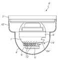
한편 도 2a에 나타낸 바와 같이, 좀더 멀리 촬영하기 위해서 케이싱(7') 및 렌즈(6')를 상방으로 최대한 들어올릴 경우 센서(9')가 커버(4')의 상단(42')에 가려지게 되므로 기능이 저하되는 문제점이 있었다.On the other hand, as shown in FIG. 2A, when the casing 7 'and the lens 6' are lifted upward as much as possible to take a further picture, the
즉 커버(4')는 투명재질이지만 상단(42')은 불투명재질이므로 센싱의 오류를 발생하게 되는 것이다.That is, the cover 4 'is made of a transparent material, but the
따라서 이러한 문제를 해결하기 위해 도 2b에 나타낸 바와 같이, 하우징(8')을 회전시켜 센서(9')의 설치위치를 노브(64')의 위치였던 하부로 바꾸고, 노브(64')를 센서(9')가 있던 위치인 상부로 바꿔서 사용하였으나 이 경우 노브(64')가 상부로 이동됨으로써 높이가 상승하게 되므로 천장에 설치된 상태에서는 손으로 조작하기가 어려운 문제점이 발생되었다.Therefore, to solve this problem, as shown in FIG. 2B, the housing 8 'is rotated to change the installation position of the
또한 종래에는 노브(64')가 결합되는 작동공(74')이 케이싱(7')의 일부분을 차지하고 있으므로 이 부위에는 엘이디(72')를 식재하지 못하게 되는 공간, 이른바 데드존이 생기게 되므로 적외선 방사 성능이 저하되는 문제점이 있었다.In addition, since the operating hole 74 'to which the knob 64' is conventionally occupies a portion of the casing 7 ', a space for preventing the planting of the LED 72', which is called a dead zone, is created in this region. There was a problem that the spinning performance is lowered.
본 발명은 상기한 종래 기술의 문제점을 해소하기 위해 안출된 것으로, 센서 및 엘이디가 식재된 케이싱 만을 회전시킬 수 있으므로 센서의 위치를 자유자재로 변경 가능하므로 카메라 모듈의 각도조절을 임으로 하여도 센서가 가려져 오작동을 일으키는 것을 방지하며 아울러 센서의 오작동/오류가 없어 신뢰성이 향상되는 돔형 감시카메라를 제공하는데 목적이 있다.The present invention has been made in order to solve the above problems of the prior art, the sensor and the LED can be rotated only the casing is planted, so the position of the sensor can be changed freely, so even if the sensor to adjust the angle of the camera module It aims to provide a dome-type surveillance camera which prevents a malfunction caused by being blocked and also improves reliability because there is no malfunction / error of a sensor.
또한 본 발명은 센서가 장착된 케이싱이 브라켓으로 부터 분리 개폐되어 노브를 용이하게 조절할 수 있도록 편리성을 갖는 돔형 감시카메라를 제공하는데 다른 목적이 있다.In another aspect, the present invention is to provide a dome-type surveillance camera having a convenience that the casing equipped with the sensor can be opened and closed separately from the bracket to easily adjust the knob.
상기한 본 발명의 목적은, 회로부가 설치된 하우징; 상기 하우징에 결합되는 반구형의 커버; 노브가 돌출된 경통에 결합된 렌즈가 중앙에 장착되고, 상면에 다수의 엘이디가 식재된 케이싱을 갖는 카메라 모듈; 상기 하우징에 형성되어 상기 카메라 모듈의 케이싱이 회전 및 개폐가능하도록 결합되는 브라켓;으로 구성되며, 상기 케이싱은, 반구형이며 중심부에 렌즈가 결합되는 통공이 형성되고, 하단의 내측으로 환형의 결합턱이 형성된 것이며, 상기 브라켓은, 상단에 개구부가 형성된 원통체로써, 상기 개구부의 상단에 상기 케이싱이 결합되는 확개부가 형성되고, 측면이 절개되어 상기 노브가 삽입되는 절개홈이 형성된 돔형 감시카메라에 의해 달 성될 수 있다.An object of the present invention described above, the circuit unit is installed; A hemispherical cover coupled to the housing; A camera module having a casing coupled to the barrel through which the knob protrudes and having a casing having a plurality of LEDs planted thereon; A bracket formed in the housing and coupled to the casing of the camera module so as to be rotatable and openable. The casing has a hemispherical shape, and a through hole is formed in which a lens is coupled to a central portion thereof. The bracket is a cylindrical body having an opening formed at an upper end thereof. The bracket is formed at an upper end of the opening by a dome-shaped surveillance camera having an incision groove formed therein and an incision groove into which a side is cut to insert the knob. Can be made.
상기 확개부는, 상기 개구부의 상단에서 수평으로 연장된 수평환부와, 상기 수평환부의 끝단에서 수직으로 연장된 환턱과, 상기 수평환부에 호형의 가이드돌기가 돌출되어 가이드홈이 형성되어 브라켓의 상단보다 직경이 확장된 것으로, 상기 브라켓의 가이드홈에 상기 케이싱의 결합턱이 결합되어 회전 및 개폐될 수 있도록 한 것을 특징으로 한다.The enlarged portion includes a horizontal annulus extending horizontally from an upper end of the opening, an annulus extending vertically from an end of the horizontal annular portion, and an arc-shaped guide protrusion protruding from the horizontal annular portion to form a guide groove, thereby forming a guide groove. It is characterized in that the diameter is extended, the coupling jaw of the casing is coupled to the guide groove of the bracket to be rotated and opened and closed.
삭제delete
본 발명에 따르면, 센서 및 엘이디가 식재된 케이싱 만을 회전시킬 수 있으므로 센서의 위치를 자유자재로 변경 가능하므로 카메라 모듈의 각도조절을 임으로 하여도 센서가 가려져 오작동을 일으키는 것을 방지하며 아울러 센서의 오작동/오류가 없어 신뢰성이 향상과 센서가 장착된 케이싱이 브라켓으로 부터 용이하게 분리 및 개폐되어 노브를 용이하게 조절할 수 있는 편리성 등의 효과가 있는 유용한 발명이다.According to the present invention, since only the sensor and the LED can be rotated casing is planted, the position of the sensor can be changed freely, so even if the angle of the camera module is adjusted, the sensor is covered and prevents malfunctions. It is a useful invention that improves reliability and there is no error, and a casing equipped with a sensor is easily separated and opened from a bracket, so that the convenience of adjusting a knob can be easily adjusted.
삭제delete
이하 본 발명의 바람직한 실시예를 첨부된 도면을 토대로 상세하게 설명하면 다음과 같다.Hereinafter, exemplary embodiments of the present invention will be described in detail with reference to the accompanying drawings.
도 3은 본 발명에 따른 돔형 감시카메라를 나타낸 분해사시도, 도 4는 본 발명에 따른 돔형 감시카메라를 나타낸 결합 측면도, 도 5a 내지 도 5b는 본 발명에 따른 돔형 감시카메라의 작동예를 나타낸 결합 측면도이다.Figure 3 is an exploded perspective view showing a dome-type surveillance camera according to the present invention, Figure 4 is a side view of the combination showing a dome-type surveillance camera according to the present invention, Figures 5a to 5b is a side view of the combined operation of the dome-type surveillance camera according to the present invention. to be.
도 3 내지 도 5에 나타낸 바와 같이, 본 발명에 따른 돔형 감시카메라(A)는,3 to 5, the dome-shaped monitoring camera A according to the present invention,
회로부가 설치된 하우징(2);A
상기 하우징(2)에 결합되는 커버(4);A
노브(64)가 돌출된 경통(62)에 결합된 렌즈(6)가 중앙에 장착되고, 상면에 다수의 엘이디(72)가 식재되며, 센서(9)가 장착된 케이싱(7)을 갖는 카메라 모듈;A camera having a
상기 하우징(2)에 형성되어 상기 케이싱(7)이 회전 및 개폐가능하도록 결합되는 브라켓(8)으로 구성된다.It is composed of a bracket (8) formed in the housing (2) to which the casing (7) is coupled to be rotatable and openable.
특히 상기 케이싱(7)은, 반구형이며 중심부에 상기 렌즈(6)가 결합되고, 하단에는 환형의 결합턱(73)이 형성된다.In particular, the casing (7), hemispherical and the
상기 결합턱(73)은 하단에 돌출된 원형으로써 케이싱(7)의 직경보다 작은 직경으로 형성된다.The
또한 상기 브라켓(8)은, 케이싱(7)의 결합턱(73)이 결합된 채 수평방향으로 회전될 수 있도록 안내하기 위한 것으로, 상단에 개구부가 형성된 원통체로써, 상기 개구부의 상단에 케이싱(7)이 결합되는 확개부(82)가 형성되고, 측면이 절개되 어 노브(64)가 삽입되는 절개홈(80)이 형성된다.In addition, the
상기 확개부(82)는 브라켓(8)의 상단에 형성되되 브라켓(8)의 상단보다 직경이 확장됨으로써, 케이싱(7)의 결합턱(73)이 끼워져 삽입될 수 있도록 하기 위한 것이다.The
상기 확개부(82)는 브라켓(8)의 상단 개구부에서 수평으로 연장된 수평환부(821)와, 상기 수평환부(821)의 끝단에서 수직으로 연장된 환턱(822)과, 상기 수평환부(821)에 호형의 가이드돌기(823)가 돌출되어 형성된 가이드홈(824)을 포함하여 구성된다. The
따라서 상기 가이드홈(824)에 상기 케이싱(7)의 결합턱(73)이 결합되어 회전될 수 있는 것이다.Therefore, the
상기 노브(64)는 케이싱(7)의 하단에 형성된 결합턱(73) 보다 더 하부에 위치되며, 상기 절개홈(80)을 관통하여 외부로 노출되도록 장착된다.The
따라서 노브(64)는 절개홈(80) 내에서 회전작동되며, 이에 따라 경통을 회전시켜 렌즈(6)의 초점을 조절할 수 있게 된다.Therefore, the
이하 본 발명의 작동예를 설명한다.Hereinafter, an operation example of the present invention will be described.
도 5a에 도시된 바와 같이, 케이싱(7) 및 렌즈(6)를 상향 조정하면 센서(9)가 커버(4')의 상단(42')에 가려지게 된다.As shown in FIG. 5A, upward adjustment of the
이를 해소하기 위해 도 5b에 도시된 바와 같이, 케이싱(7)을 회전시켜 센서(9)가 하방으로 위치되도록 하는 것이다.In order to solve this, as shown in FIG. 5B, the
이렇게 케이싱(7)을 회전시키더라도 그 회전동작을 노브(64)가 방해하지 않으므로, 즉 노브(64)는 케이싱(7)의 하부로부터 벗어나 있으므로 센서(9)의 위치를 상단에 배치하거나 또는 하단에 배치할 수 있어 사실상 자유로운 위치 설정이 가능해진다.
이를 좀더 구체적으로 살펴보면 첨부도면 도 6a 내지 도 6d에 도시된 바와 같이 센서(9)가 설치된 케이싱(7)이 0도에서 360도 회전이 자유로이 가능함으로 센서(9) 및 엘이디(72)가 식재된 케이싱(7) 만을 회전시킬 수 있으므로 센서(9)의 위치를 자유자재로 변경 가능하므로 카메라 모듈의 각도조절을 임으로 하여도 센서(9)가 가려져 오작동을 일으키는 것을 방지하여 상기 센서(9)의 오작동/오류가 없어 신뢰성이 향상되는 것이다.
상기 노브(64)의 위치 변경 없이 조절이 가능하지만 첨부도면 도 7에 도시된 바와 같이 브라켓(8)에서 케이싱(7)을 용이하게 분리 및 개폐시킬 수 있어 노브(64)를 이용한 렌즈(6)의 초점을 용이하게 조절할 수 있게 된다.Even if the
More specifically, as shown in the accompanying drawings, FIGS. 6A to 6D, the
The
비록 본 발명이 상기 언급된 바람직한 실시예와 관련하여 설명되어졌지만, 발명의 요지와 범위로부터 벗어남이 없이 다양한 수정 및 변형이 가능한 것은 당업자라면 용이하게 인식할 수 있을 것이며, 이러한 변경 및 수정은 모두 첨부된 청구의 범위에 속함은 자명하다.Although the present invention has been described in connection with the above-mentioned preferred embodiments, it will be apparent to those skilled in the art that various modifications and variations can be made without departing from the spirit and scope of the invention, It is obvious that the claims fall within the scope of the claims.
도 1은 종래 돔형 감시카메라를 나타낸 측면도,1 is a side view showing a conventional dome type surveillance camera,
도 2a 내지 도 2b는 종래 돔형 감시카메라의 작동예를 나타낸 측면도.Figure 2a to 2b is a side view showing an operation example of a conventional dome-type surveillance camera.
도 3은 본 발명에 따른 돔형 감시카메라를 나타낸 분해사시도.Figure 3 is an exploded perspective view showing a dome-type surveillance camera according to the present invention.
도 4는 본 발명에 따른 돔형 감시카메라를 나타낸 결합 측면도.Figure 4 is a side view of the combined domed surveillance camera according to the present invention.
도 5a 내지 도 5b는 본 발명에 따른 돔형 감시카메라의 작동예를 나타낸 결합 측면도.
도 6a 내지 도 6c는 본 발명의 기술적 요지인 케이싱의 회전 모습을 보여주는 정면도.
도 7은 본 발명의 기술적 요지인 케이싱과 브라켓의 분해 구조를 보여주는 일부발췌 분해사시도.5A to 5B are combined side views showing an example of the operation of the dome-type surveillance camera according to the present invention.
6a to 6c is a front view showing a rotating state of the casing which is the technical gist of the present invention.
Figure 7 is a partial exploded perspective view showing the decomposition structure of the casing and the bracket which is the technical gist of the present invention.
* 도면의 주요 부분에 대한 부호의 설명 *Explanation of symbols on the main parts of the drawings
2 : 하우징 4 : 커버2: housing 4: cover
6 : 렌즈 7 : 케이싱6: lens 7: casing
8 : 브라켓 9 : 센서8: Bracket 9: Sensor
64 : 노브 72 : 엘이디64: knob 72: LED
Claims (4)
Translated fromKoreanPriority Applications (2)
| Application Number | Priority Date | Filing Date | Title |
|---|---|---|---|
| KR1020090134633AKR101011636B1 (en) | 2009-12-30 | 2009-12-30 | Dome type surveillance camera |
| US12/830,037US8337100B2 (en) | 2009-12-30 | 2010-07-02 | Dome security camera |
Applications Claiming Priority (1)
| Application Number | Priority Date | Filing Date | Title |
|---|---|---|---|
| KR1020090134633AKR101011636B1 (en) | 2009-12-30 | 2009-12-30 | Dome type surveillance camera |
Publications (1)
| Publication Number | Publication Date |
|---|---|
| KR101011636B1true KR101011636B1 (en) | 2011-01-31 |
Family
ID=43616927
Family Applications (1)
| Application Number | Title | Priority Date | Filing Date |
|---|---|---|---|
| KR1020090134633AExpired - Fee RelatedKR101011636B1 (en) | 2009-12-30 | 2009-12-30 | Dome type surveillance camera |
Country Status (2)
| Country | Link |
|---|---|
| US (1) | US8337100B2 (en) |
| KR (1) | KR101011636B1 (en) |
Cited By (2)
| Publication number | Priority date | Publication date | Assignee | Title |
|---|---|---|---|---|
| KR101450102B1 (en) | 2013-09-16 | 2014-10-13 | 주식회사하이트론씨스템즈 | Separating device for dome type security camera |
| WO2019212103A1 (en)* | 2018-05-02 | 2019-11-07 | (주)씨프로 | Camera device having slide fastening structure enabling adjustment of monitoring position from outside thereof |
Families Citing this family (33)
| Publication number | Priority date | Publication date | Assignee | Title |
|---|---|---|---|---|
| KR101293484B1 (en)* | 2010-09-16 | 2013-08-06 | 주식회사 씨앤비텍 | Apparatus for Preventing Scattered Reflection of Lighting in Monitoring Camera |
| US9071740B1 (en) | 2011-10-28 | 2015-06-30 | Google Inc. | Modular camera system |
| USD721755S1 (en) | 2011-12-22 | 2015-01-27 | Axis Ab | Monitoring camera |
| US20130169814A1 (en)* | 2011-12-28 | 2013-07-04 | Da-Ming Liu | Lamp socket type camera |
| US9197686B1 (en) | 2012-01-06 | 2015-11-24 | Google Inc. | Backfill of video stream |
| USD726800S1 (en)* | 2012-03-14 | 2015-04-14 | Axis Ab | Surveillance camera |
| US9291880B2 (en)* | 2013-01-30 | 2016-03-22 | Spark Facter Design | Mobile device light meter attachment |
| US20150015703A1 (en)* | 2013-07-09 | 2015-01-15 | The Pennsylvania Globe Gaslight Co. | Energy efficient lighting platform and system |
| WO2016079570A1 (en)* | 2014-11-21 | 2016-05-26 | Gtk Indústria E Comércio De Produtos Eletrônicos Ltda | Arrangement applied to camera for security systems |
| JP6080057B2 (en)* | 2015-02-26 | 2017-02-15 | パナソニックIpマネジメント株式会社 | Imaging device |
| US9544485B2 (en) | 2015-05-27 | 2017-01-10 | Google Inc. | Multi-mode LED illumination system |
| US9235899B1 (en) | 2015-06-12 | 2016-01-12 | Google Inc. | Simulating an infrared emitter array in a video monitoring camera to construct a lookup table for depth determination |
| US9613423B2 (en) | 2015-06-12 | 2017-04-04 | Google Inc. | Using a depth map of a monitored scene to identify floors, walls, and ceilings |
| US9626849B2 (en) | 2015-06-12 | 2017-04-18 | Google Inc. | Using scene information from a security camera to reduce false security alerts |
| US9554063B2 (en) | 2015-06-12 | 2017-01-24 | Google Inc. | Using infrared images of a monitored scene to identify windows |
| US9454820B1 (en) | 2015-06-12 | 2016-09-27 | Google Inc. | Using a scene illuminating infrared emitter array in a video monitoring camera for depth determination |
| US9386230B1 (en) | 2015-06-12 | 2016-07-05 | Google Inc. | Day and night detection based on one or more of illuminant detection, lux level detection, and tiling |
| US9886620B2 (en) | 2015-06-12 | 2018-02-06 | Google Llc | Using a scene illuminating infrared emitter array in a video monitoring camera to estimate the position of the camera |
| WO2017092369A1 (en)* | 2015-12-03 | 2017-06-08 | 北京小鸟看看科技有限公司 | Head-mounted device, three-dimensional video call system and three-dimensional video call implementation method |
| US10215384B2 (en) | 2016-04-25 | 2019-02-26 | The Pennsylvania Globe Gaslight Co. | Extension module with housing for electronic components |
| EP3244125A1 (en)* | 2016-05-13 | 2017-11-15 | Stephane Bochenek | Lighting device made up of luminous elements and striplight made up of a plurality of such lighting devices |
| US10591648B2 (en) | 2016-06-01 | 2020-03-17 | Arlo Technologies, Inc. | Camera with polygonal lens |
| USD849114S1 (en)* | 2016-10-11 | 2019-05-21 | Hanwha Aerospace Co., Ltd. | Surveillance camera |
| US10180615B2 (en) | 2016-10-31 | 2019-01-15 | Google Llc | Electrochromic filtering in a camera |
| USD824985S1 (en)* | 2016-12-28 | 2018-08-07 | Cisco Technology, Inc. | Camera housing with mount |
| JP1604344S (en) | 2017-03-31 | 2018-05-21 | ||
| JP1610516S (en)* | 2017-05-31 | 2018-08-06 | ||
| USD861058S1 (en) | 2017-05-31 | 2019-09-24 | Axis Ab | Monitoring camera |
| WO2018223230A1 (en)* | 2017-06-05 | 2018-12-13 | Avigilon Corporation | Spherical camera |
| JP2019061055A (en)* | 2017-09-26 | 2019-04-18 | キヤノン株式会社 | Imaging device |
| WO2019143250A1 (en)* | 2018-01-22 | 2019-07-25 | Fugro N.V. | Surveying instrument for and surveying method of surveying reference points |
| JP2019186699A (en)* | 2018-04-06 | 2019-10-24 | キヤノン株式会社 | Imaging apparatus |
| US11112683B1 (en)* | 2020-08-24 | 2021-09-07 | Motorola Solutions, Inc. | Camera with infrared module |
Citations (2)
| Publication number | Priority date | Publication date | Assignee | Title |
|---|---|---|---|---|
| KR20090024567A (en)* | 2007-09-04 | 2009-03-09 | 엘지전자 주식회사 | Adapter device for surveillance camera |
| KR100917242B1 (en)* | 2007-11-16 | 2009-09-16 | 주식회사 케이티앤씨 | Camera module assembly and surveillance camera having same |
Family Cites Families (2)
| Publication number | Priority date | Publication date | Assignee | Title |
|---|---|---|---|---|
| US5394184A (en)* | 1993-08-30 | 1995-02-28 | Sensormatic Electronics Corporation | Surveillance assembly having circumferential delivery of forced air to viewing bubble |
| JP2008022120A (en) | 2006-07-11 | 2008-01-31 | Elmo Co Ltd | Imaging device |
- 2009
- 2009-12-30KRKR1020090134633Apatent/KR101011636B1/ennot_activeExpired - Fee Related
- 2010
- 2010-07-02USUS12/830,037patent/US8337100B2/ennot_activeExpired - Fee Related
Patent Citations (2)
| Publication number | Priority date | Publication date | Assignee | Title |
|---|---|---|---|---|
| KR20090024567A (en)* | 2007-09-04 | 2009-03-09 | 엘지전자 주식회사 | Adapter device for surveillance camera |
| KR100917242B1 (en)* | 2007-11-16 | 2009-09-16 | 주식회사 케이티앤씨 | Camera module assembly and surveillance camera having same |
Cited By (2)
| Publication number | Priority date | Publication date | Assignee | Title |
|---|---|---|---|---|
| KR101450102B1 (en) | 2013-09-16 | 2014-10-13 | 주식회사하이트론씨스템즈 | Separating device for dome type security camera |
| WO2019212103A1 (en)* | 2018-05-02 | 2019-11-07 | (주)씨프로 | Camera device having slide fastening structure enabling adjustment of monitoring position from outside thereof |
Also Published As
| Publication number | Publication date |
|---|---|
| US20110158637A1 (en) | 2011-06-30 |
| US8337100B2 (en) | 2012-12-25 |
Similar Documents
| Publication | Publication Date | Title |
|---|---|---|
| KR101011636B1 (en) | Dome type surveillance camera | |
| KR100847088B1 (en) | Speed dome security camera | |
| KR101047156B1 (en) | Dome type surveillance camera with infrared LED | |
| KR101899489B1 (en) | A camera device having a slide fastening structure capable of adjusting a monitoring position from the outside | |
| KR100938153B1 (en) | The dome type supervisory camera where the diffused reflection prevention pad attaches | |
| JP2003008954A (en) | Dome type surveillance camera device | |
| KR100736446B1 (en) | Dome type surveillance camera | |
| KR200455617Y1 (en) | Infrared Camera Light Blocker | |
| KR20080011962A (en) | Dome camera device | |
| US6844555B2 (en) | Covering and mounting structure for a motion detector having light emitting diodes and electronic adjustment controls | |
| KR100671223B1 (en) | Dome Infrared Surveillance Camera | |
| KR200342138Y1 (en) | Dome type camera | |
| KR101706719B1 (en) | Depending on the focus moves to the LED dome type CCTV camera | |
| KR101066905B1 (en) | Dome type surveillance camera | |
| JP4273498B2 (en) | Dome-type surveillance camera device | |
| KR101899494B1 (en) | A camera device having a magnet fastening structure capable of adjusting a monitoring position from the outside | |
| KR102001164B1 (en) | CCTV camera of dom type | |
| US12353116B2 (en) | Monitoring device | |
| KR20100008194U (en) | Dome type camera for preventing diffused reflection | |
| KR200320712Y1 (en) | Camera with pantilt | |
| AU2022224774A1 (en) | Triaxial dome-type surveillance camera | |
| KR100932146B1 (en) | Dome type surveillance camera | |
| JP2008035105A (en) | Front door slave unit with camera for interphone device | |
| KR101369894B1 (en) | Sensor light capable of adjusting sensing angle | |
| KR20220166151A (en) | A pan tilt zoom camera device with bubble structure for removing diffuse reflection |
Legal Events
| Date | Code | Title | Description |
|---|---|---|---|
| A201 | Request for examination | ||
| PA0109 | Patent application | St.27 status event code:A-0-1-A10-A12-nap-PA0109 | |
| PA0201 | Request for examination | St.27 status event code:A-1-2-D10-D11-exm-PA0201 | |
| P11-X000 | Amendment of application requested | St.27 status event code:A-2-2-P10-P11-nap-X000 | |
| P13-X000 | Application amended | St.27 status event code:A-2-2-P10-P13-nap-X000 | |
| R15-X000 | Change to inventor requested | St.27 status event code:A-3-3-R10-R15-oth-X000 | |
| R16-X000 | Change to inventor recorded | St.27 status event code:A-3-3-R10-R16-oth-X000 | |
| A302 | Request for accelerated examination | ||
| PA0302 | Request for accelerated examination | St.27 status event code:A-1-2-D10-D17-exm-PA0302 St.27 status event code:A-1-2-D10-D16-exm-PA0302 | |
| E902 | Notification of reason for refusal | ||
| PE0902 | Notice of grounds for rejection | St.27 status event code:A-1-2-D10-D21-exm-PE0902 | |
| AMND | Amendment | ||
| E13-X000 | Pre-grant limitation requested | St.27 status event code:A-2-3-E10-E13-lim-X000 | |
| P11-X000 | Amendment of application requested | St.27 status event code:A-2-2-P10-P11-nap-X000 | |
| P13-X000 | Application amended | St.27 status event code:A-2-2-P10-P13-nap-X000 | |
| E601 | Decision to refuse application | ||
| PE0601 | Decision on rejection of patent | St.27 status event code:N-2-6-B10-B15-exm-PE0601 | |
| X091 | Application refused [patent] | ||
| AMND | Amendment | ||
| E13-X000 | Pre-grant limitation requested | St.27 status event code:A-2-3-E10-E13-lim-X000 | |
| J201 | Request for trial against refusal decision | ||
| P11-X000 | Amendment of application requested | St.27 status event code:A-2-2-P10-P11-nap-X000 | |
| PJ0201 | Trial against decision of rejection | St.27 status event code:A-3-3-V10-V11-apl-PJ0201 | |
| AMND | Amendment | ||
| E13-X000 | Pre-grant limitation requested | St.27 status event code:A-2-3-E10-E13-lim-X000 | |
| P11-X000 | Amendment of application requested | St.27 status event code:A-2-2-P10-P11-nap-X000 | |
| P13-X000 | Application amended | St.27 status event code:A-2-2-P10-P13-nap-X000 | |
| PX0901 | Re-examination | St.27 status event code:A-2-3-E10-E12-rex-PX0901 | |
| J121 | Written withdrawal of request for trial | ||
| PJ1201 | Withdrawal of trial | St.27 status event code:A-3-3-V10-V13-apl-PJ1201 | |
| P11-X000 | Amendment of application requested | St.27 status event code:A-2-2-P10-P11-nap-X000 | |
| P13-X000 | Application amended | St.27 status event code:A-2-2-P10-P13-nap-X000 | |
| R15-X000 | Change to inventor requested | St.27 status event code:A-3-3-R10-R15-oth-X000 | |
| R16-X000 | Change to inventor recorded | St.27 status event code:A-3-3-R10-R16-oth-X000 | |
| PX0701 | Decision of registration after re-examination | St.27 status event code:A-3-4-F10-F13-rex-PX0701 | |
| X701 | Decision to grant (after re-examination) | ||
| GRNT | Written decision to grant | ||
| PR0701 | Registration of establishment | St.27 status event code:A-2-4-F10-F11-exm-PR0701 | |
| PR1002 | Payment of registration fee | St.27 status event code:A-2-2-U10-U11-oth-PR1002 Fee payment year number:1 | |
| PG1601 | Publication of registration | St.27 status event code:A-4-4-Q10-Q13-nap-PG1601 | |
| J206 | Request for trial to confirm the scope of a patent right | ||
| PJ0206 | Trial to confirm the scope of a patent | St.27 status event code:A-5-5-V10-V11-apl-PJ0206 | |
| J301 | Trial decision | Free format text:TRIAL DECISION FOR CONFIRMATION OF THE SCOPE OF RIGHT_AFFIRMATIVE REQUESTED 20110405 Effective date:20110930 | |
| PJ1301 | Trial decision | St.27 status event code:A-5-5-V10-V15-crt-PJ1301 Decision date:20110930 Appeal event data comment text:Appeal Kind Category : Confirmation of the scope of right_affirmative, Appeal Ground Text : 1011636 Appeal request date:20110405 Appellate body name:Patent Examination Board Decision authority category:Office appeal board Decision identifier:2011100000771 | |
| J2X1 | Appeal (before the patent court) | Free format text:CONFIRMATION OF THE SCOPE OF RIGHT_AFFIRMATIVE | |
| PJ2001 | Appeal | St.27 status event code:A-5-5-V10-V12-crt-PJ2001 | |
| J121 | Written withdrawal of request for trial | ||
| PJ1201 | Withdrawal of trial | St.27 status event code:A-5-5-V10-V13-apl-PJ1201 | |
| J122 | Written withdrawal of action (patent court) | ||
| PJ1202 | Withdrawal of action (patent court) | St.27 status event code:A-5-5-V10-V13-crt-PJ1202 | |
| FPAY | Annual fee payment | Payment date:20140107 Year of fee payment:6 | |
| PR1001 | Payment of annual fee | St.27 status event code:A-4-4-U10-U11-oth-PR1001 Fee payment year number:4 | |
| R18-X000 | Changes to party contact information recorded | St.27 status event code:A-5-5-R10-R18-oth-X000 | |
| FPAY | Annual fee payment | Payment date:20170119 Year of fee payment:7 | |
| PR1001 | Payment of annual fee | St.27 status event code:A-4-4-U10-U11-oth-PR1001 Fee payment year number:7 | |
| FPAY | Annual fee payment | Payment date:20180326 Year of fee payment:8 | |
| PR1001 | Payment of annual fee | St.27 status event code:A-4-4-U10-U11-oth-PR1001 Fee payment year number:8 | |
| FPAY | Annual fee payment | Payment date:20190225 Year of fee payment:9 | |
| PR1001 | Payment of annual fee | St.27 status event code:A-4-4-U10-U11-oth-PR1001 Fee payment year number:9 | |
| PR1001 | Payment of annual fee | St.27 status event code:A-4-4-U10-U11-oth-PR1001 Fee payment year number:10 | |
| PN2301 | Change of applicant | St.27 status event code:A-5-5-R10-R11-asn-PN2301 | |
| PN2301 | Change of applicant | St.27 status event code:A-5-5-R10-R14-asn-PN2301 | |
| P14-X000 | Amendment of ip right document requested | St.27 status event code:A-5-5-P10-P14-nap-X000 | |
| PR1001 | Payment of annual fee | St.27 status event code:A-4-4-U10-U11-oth-PR1001 Fee payment year number:11 | |
| PC1903 | Unpaid annual fee | St.27 status event code:A-4-4-U10-U13-oth-PC1903 Not in force date:20220125 Payment event data comment text:Termination Category : DEFAULT_OF_REGISTRATION_FEE | |
| PC1903 | Unpaid annual fee | St.27 status event code:N-4-6-H10-H13-oth-PC1903 Ip right cessation event data comment text:Termination Category : DEFAULT_OF_REGISTRATION_FEE Not in force date:20220125 |