KR101009774B1 - Spatial Modulation in Multiple Input and Output Systems and Transceivers Using the Same - Google Patents
Spatial Modulation in Multiple Input and Output Systems and Transceivers Using the SameDownload PDFInfo
- Publication number
- KR101009774B1 KR101009774B1KR1020060064934AKR20060064934AKR101009774B1KR 101009774 B1KR101009774 B1KR 101009774B1KR 1020060064934 AKR1020060064934 AKR 1020060064934AKR 20060064934 AKR20060064934 AKR 20060064934AKR 101009774 B1KR101009774 B1KR 101009774B1
- Authority
- KR
- South Korea
- Prior art keywords
- signal
- antenna
- symbol
- antenna index
- vector
- Prior art date
- Legal status (The legal status is an assumption and is not a legal conclusion. Google has not performed a legal analysis and makes no representation as to the accuracy of the status listed.)
- Expired - Fee Related
Links
Images


Classifications
- H—ELECTRICITY
- H04—ELECTRIC COMMUNICATION TECHNIQUE
- H04L—TRANSMISSION OF DIGITAL INFORMATION, e.g. TELEGRAPHIC COMMUNICATION
- H04L1/00—Arrangements for detecting or preventing errors in the information received
- H04L1/02—Arrangements for detecting or preventing errors in the information received by diversity reception
- H04L1/06—Arrangements for detecting or preventing errors in the information received by diversity reception using space diversity
- H04L1/0618—Space-time coding
- H04L1/0637—Properties of the code
- H04L1/0656—Cyclotomic systems, e.g. Bell Labs Layered Space-Time [BLAST]
- H—ELECTRICITY
- H04—ELECTRIC COMMUNICATION TECHNIQUE
- H04B—TRANSMISSION
- H04B7/00—Radio transmission systems, i.e. using radiation field
- H04B7/02—Diversity systems; Multi-antenna system, i.e. transmission or reception using multiple antennas
- H04B7/04—Diversity systems; Multi-antenna system, i.e. transmission or reception using multiple antennas using two or more spaced independent antennas
- H04B7/0413—MIMO systems
- H—ELECTRICITY
- H04—ELECTRIC COMMUNICATION TECHNIQUE
- H04B—TRANSMISSION
- H04B7/00—Radio transmission systems, i.e. using radiation field
- H04B7/02—Diversity systems; Multi-antenna system, i.e. transmission or reception using multiple antennas
- H04B7/04—Diversity systems; Multi-antenna system, i.e. transmission or reception using multiple antennas using two or more spaced independent antennas
- H04B7/06—Diversity systems; Multi-antenna system, i.e. transmission or reception using multiple antennas using two or more spaced independent antennas at the transmitting station
- H04B7/0686—Hybrid systems, i.e. switching and simultaneous transmission
- H04B7/0691—Hybrid systems, i.e. switching and simultaneous transmission using subgroups of transmit antennas
- H—ELECTRICITY
- H04—ELECTRIC COMMUNICATION TECHNIQUE
- H04L—TRANSMISSION OF DIGITAL INFORMATION, e.g. TELEGRAPHIC COMMUNICATION
- H04L1/00—Arrangements for detecting or preventing errors in the information received
- H04L1/004—Arrangements for detecting or preventing errors in the information received by using forward error control
- H04L1/0056—Systems characterized by the type of code used
- H04L1/0061—Error detection codes
- H04L1/0063—Single parity check
Landscapes
- Engineering & Computer Science (AREA)
- Computer Networks & Wireless Communication (AREA)
- Signal Processing (AREA)
- Radio Transmission System (AREA)
Abstract
Translated fromKorean
Description
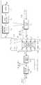
Translated fromKorean도 1은 본 발명의 실시예에 따른 신호 공간 다중화(signal space multiplexing :SSM) 방법을 이용한 다중입출력(MIMO) 시스템을 나타내는 도면,1 is a diagram illustrating a multiple input and output (MIMO) system using a signal space multiplexing (SSM) method according to an embodiment of the present invention;
도 2는 본 발명의 실시예에 따른 공간 변조(spatial modulation :SM)를 이용한 다중입출력 시스템을 나타내는 도면,2 is a diagram illustrating a multiple input / output system using spatial modulation (SM) according to an embodiment of the present invention;
도 3은 본 발명의 실시예에 따른 공간 변조 방법을 나타내는 도면,3 is a diagram illustrating a spatial modulation method according to an embodiment of the present invention;
도 4는 본 발명의 실시예에 따른 SM-OFDM 시스템을 나타내는 도면,4 illustrates an SM-OFDM system according to an embodiment of the present invention;
도 5는 본 발명의 실시예에 따른 SM-OFDM 방법을 나타내는 도면,5 is a diagram showing a SM-OFDM method according to an embodiment of the present invention;
도 6 내지 도 10은 본 발명의 시물레이션 결과를 나타내는 도면.6 to 10 are diagrams showing the simulation results of the present invention.
본 발명은 다중입출력 시스템의 공간 변조 방법 및 그를 이용한 송수신 장치에 관한 것으로서, 특히 다중입출력 시스템에서 공간 변조 방법을 이용한 송신 장 치 및 반복적으로 최대 비율을 결합(iterative maximum ratio combining: i-MRC) 하는 공간 변조 검출 방법을 이용한 수신 장치에 관한 것이다.BACKGROUND OF THE
무선 통신은 최근 몇 년간 괄목할만한 성장을 보여왔으며, 3G(3rd-generation)에서 4G(4th-generation) 광대역 무선 통신으로 진행 중에 있다. 무선 통신 환경에 따르면 송신기에서 발생된 무선 신호는 수신기로 직접적으로 전송되지 않고, 다중경로 전파를 따른다. 이에 따라, 다중 경로로부터 발생하는 신호 왜곡(distortion)을 줄이는 것은 중요한 문제가 된다.Wireless communications have shown significant growth in recent years and are moving from 3rd-generation (3G) to 4th-generation (4G) broadband wireless communications. According to a wireless communication environment, a radio signal generated from a transmitter is not transmitted directly to a receiver, but follows a multipath propagation. Accordingly, reducing signal distortion resulting from multiple paths is an important problem.
한편, 다중입출력(MIMO) 시스템은 SISO(single-input single-output) 무선 시스템에 비해 용량적으로 효율성이 좋고 품질이 뛰어나다. 하지만 다중입출력 시스템은 용량 이득(capacity gains)을 높이기 위해 해결해야 할 과제가 많이 남아있다. 다시 말하면, 다중입출력에서의 전송은 송신 및 수신 안테나의 공간적 배치에 크게 좌우되고, 송신 안테나의 동기화가 필요하다. 또한, 다중입출력에서의 전송은 사용할 수 있는 알고리즘이 부족하고, 수신 장치에서 채널간 간섭이 존재한다.On the other hand, MIMO systems are more capacitively efficient and of higher quality than single-input single-output (SISO) wireless systems. However, multiple I / O systems have many challenges to address to increase capacity gains. In other words, transmission at multiple inputs and outputs is highly dependent on the spatial arrangement of the transmitting and receiving antennas, and synchronization of the transmitting antennas is required. In addition, transmission at multiple inputs and outputs lacks an algorithm that can be used, and there is interchannel interference at a receiving device.
채널간 간섭을 제거하는 알고리즘은 비교적 최근에 발표되었다. 대표적인 알고리즘으로서, BLAST(Bell Labs Layered Space-Time Architecture)는 다중입출력 검출 알고리즘을 제안했다. BLAST 중 가장 기본적인 V-BLAST(vertical-BLAST) 형태에 의하면, 다중 전송된 데이터 스트림은 어레이 프로세싱 및 간섭 제거 기술(interference cancellation technique)을 통해 분리되고 연속적으로 검출된다. 그리고, V-BLAST 다중 안테나 기술은 SNR을 높이기 위하여 공간 다이버시티를 활용한다. 이 경우, 다중입출력 시스템은 다이버시티 이득으로 인해 신호대 잡음비(SNR)가 개선된다. 하지만, 다중입출력 시스템의 병렬적 신호 전송 결과는 스펙트럼 효율이 높아질수록 왜곡이 심하다. 따라서, 왜곡 없이도 스펙트럼 효율을 증진 시킬 수 있는 방법이 요구된다.Algorithms for eliminating interchannel interference have been published relatively recently. As a representative algorithm, Bell Labs Layered Space-Time Architecture (BLAST) proposed a multi-input / output detection algorithm. According to the most basic V-BLAST (V-BLAST) form of BLAST, multiple transmitted data streams are separated and continuously detected through array processing and interference cancellation technique. The V-BLAST multi-antenna technology utilizes spatial diversity to increase SNR. In this case, the multiple input / output system improves the signal-to-noise ratio (SNR) due to the diversity gain. However, the parallel signal transmission result of a multi-input / output system is more distorted as spectral efficiency increases. Therefore, a method for improving spectral efficiency without distortion is required.
직교 주파수 분할 다중 (orthogonal frequency division multiplexing: OFDM)기술은 주파수 선택 채널(frequency selective channel)로 인한 다중경로 왜곡을 감소시키는데 효율적이다. OFDM은 주파수 선택 채널을 주파수 플랫(flat) 페이딩 채널의 병력적 모음으로 변환한다. 각 OFDM 반송파는 파형의 직교성을 유지하기 위한 최대 주파수 분할을 갖고, 신호 주파수들의 오버랩에 대응한다. 따라서, OFDM은 가용 대역폭을 매우 효율적으로 이용할 수 있다. 이러한 이유로, OFDM은 디지털 오디오 브로드캐스트(DAB), IEEE 802.11a, IEEE 802.16a의 MAN(Metropolitan Area Network), LAN(Local area Network)과 같은 무선 표준에 채택되었다. 하지만, MIMO-OFDM 시스템은 각 하위 반송파당 복조 복잡도가 높으므로, 이 복잡도를 줄이는 알고리즘을 필요로 한다.
따라서, 향상된 공간 변조 방법과 복조 복잡도를 감소하기 위하여 공간 변조를 사용하는 송수신 장치에 대한 필요성이 존재한다.Orthogonal frequency division multiplexing (OFDM) technology is effective in reducing multipath distortion due to frequency selective channel. OFDM converts a frequency selective channel into a historical collection of frequency flat fading channels. Each OFDM carrier has a maximum frequency division to maintain orthogonality of the waveform and corresponds to overlap of signal frequencies. Thus, OFDM can utilize the available bandwidth very efficiently. For this reason, OFDM has been adopted for wireless standards such as Digital Audio Broadcast (DAB), IEEE 802.11a, Metropolitan Area Network (MAN) of IEEE 802.16a, and Local Area Network (LAN). However, since the MIMO-OFDM system has a high demodulation complexity for each subcarrier, an algorithm for reducing the complexity is required.
Accordingly, there is a need for an improved spatial modulation method and a transceiver for using spatial modulation to reduce demodulation complexity.
전술한 문제점을 해결하기 위해, 본 발명은 하나의 송신 안테나만을 활성화 함으로써, 송신 안테나의 동기화가 필요 없고, 수신 장치에서 채널간 간섭이 없는 다중입출력의 시스템을 제공하고자 한다. 그리고 본 발명은 송신 안테나의 공간적 배치를 정보로 이용하여 단위 헤르츠당 전송 효율이 높일 수 있는 방법 및 이를 송신 장치를 제공하고자 한다.In order to solve the above problem, the present invention is to provide a system of multiple input and output by activating only one transmit antenna, there is no need for synchronization of the transmit antenna, there is no inter-channel interference in the receiving device. Another object of the present invention is to provide a method and a transmission apparatus capable of increasing transmission efficiency per unit hertz using spatial arrangement of a transmission antenna as information.
또한, 본 발명은 MIMO-OFDM 시스템에서 공간 다중화 이득을 얻을 수 있으면서도 수신단의 복조 복잡도를 줄일 수 있는 검출 방법 및 이를 이용한 수신 장치를 제공하고자 한다.Another object of the present invention is to provide a detection method and a receiving apparatus using the same, which can reduce the demodulation complexity of a receiver while obtaining a spatial multiplexing gain in a MIMO-OFDM system.
본 발명에 따른 다중입출력(multiple-input multiple-output) 시스템에서 공간 변조 (spatial modulation: SM) 방법은, 다수의 비트 정보를 포함하는 신호를 입력 받아 안테나 인덱스 비트 블록과 신호 변조 비트 블록으로 분리하는 단계와, 상기 신호 변조 비트 블록을 신호 변조로 부호화하는 단계와, 상기 안테나 인덱스 비트 블록을 활성화 될 안테나 인덱스로 부호화하는 단계를 포함하는 것을 특징으로 한다.In a multiple-input multiple-output system according to the present invention, a spatial modulation (SM) method includes receiving an input signal including a plurality of bit information and separating the signal into an antenna index bit block and a signal modulation bit block. And encoding the signal modulated bit block by signal modulation and encoding the antenna index bit block by an antenna index to be activated.
또한, 본 발명에 따른 다중입출력(multiple-input multiple-output) 시스템에서 공간 변조(spatial modulation: SM) 방법을 이용한 송신 장치는, 다수의 비트 정보를 포함하는 신호를 입력 받아 안테나 비트 블록과 신호 변조 비트 블록으로 분리하는 분리부와, 상기 신호 변조 비트 블록을 신호 변조로 부호화하는 신호 변조 부호화부와, 상기 안테나 비트 블록을 안테나 인덱스 부호화하는 안테나 인덱스 부호화부와, 단위 시간당 하나의 활성화 안테나에서 상기 변조된 신호를 전송하는 복수의 안테나를 포함하는 것을 특징으로 한다.In addition, in a multiple-input multiple-output system according to the present invention, a transmission apparatus using a spatial modulation (SM) method receives an antenna bit block and signal modulation by receiving a signal including a plurality of bit information. A modulation unit for separating the bit block, a signal modulation encoder for encoding the signal modulation bit block by signal modulation, an antenna index encoder for antenna index encoding the antenna bit block, and one active antenna per unit time It characterized in that it comprises a plurality of antennas for transmitting the signal.
또한, 본 발명에 따른 다중입출력 시스템에서 공간 변조 (spatial modulation: SM)를 검출하는 i-MRC(iterative maximum ratio combining) 방법은, 수신 벡터에 반복적으로 채널 패스 이득을 곱하여 검출 벡터를 계산 하는 단계와, 상기 검출 벡터의 독립변수의 최대 절대값으로 안테나 인덱스를 추정하는 단계와, 상기 안테나 인덱스 추정 값과 안테나 인덱스 값이 같을 때, 양자화 함수의 검출열 벡터 성상도로 전송된 심볼을 추정하는 단계를 포함하는 것을 특징으로 한다.In addition, an iterative maximum ratio combining (i-MRC) method for detecting spatial modulation (SM) in a multi-input / output system according to the present invention includes the steps of calculating a detection vector by repeatedly multiplying a received vector by a channel pass gain; Estimating an antenna index with a maximum absolute value of an independent variable of the detection vector, and estimating a symbol transmitted as a detection column vector constellation of a quantization function when the antenna index estimation value and the antenna index value are equal to each other. Characterized in that.
또한, 본 발명에 따른 다중입출력 시스템에서 공간 변조 (spatial modulation: SM)를 검출하는 i-MRC(iterative maximum ratio combining) 방법을 이용한 수신 장치는 송신 안테나로부터 변조된 신호를 수신하는 복수의 수신 안테나와, 상기 신호로부터 안테나 인덱스 및 전송된 심볼을 추정하는 검출(detector)부와 상기 안테나 인덱스 추정 값으로 안테나 비트 블록을 복호화하고, 상기 전송된 심볼의 추정값으로 신호 변조 비트 블록을 복호화하는 공간 복조부를 포함하는 것을 특징으로 한다.In addition, a receiving apparatus using an iterative maximum ratio combining (i-MRC) method for detecting spatial modulation (SM) in a multi-input / output system according to the present invention includes a plurality of receiving antennas for receiving a modulated signal from a transmitting antenna; And a detector for estimating the antenna index and the transmitted symbol from the signal, and a spatial demodulator for decoding the antenna bit block with the antenna index estimate and the signal modulation bit block with the estimated value of the transmitted symbol. Characterized in that.
또한 본 발명에 따른 공간 변조 (spatial modulation: SM) 방법 및 i-MRC(iterative maximum ratio combining) 방법을 이용하는 다중입출력 (Multiple-input multiple-output) 시스템은, 활성화 안테나 인덱스를 다중 심볼 신호로 부호화하는 공간 변조부와, 단위 시간당 하나의 활성화 안테나에서 상기 변조된 신호를 전송하는 복수의 송신 안테나와, 송신 안테나로부터 변조된 신호를 수신하는 복수의 수신 안테나와, 수신 신호로부터 안테나 인덱스 및 전송된 심볼을 추정하는 검출(detector)부와, 상기 공간 변조부의 신호를 복조하는 공간 복조부를 포함하는 것을 특징으로 한다.In addition, a multiple-input multiple-output (SM) system using a spatial modulation (SM) method and an iterative maximum ratio combining (i-MRC) method according to the present invention includes encoding an active antenna index into a multi-symbol signal. A spatial modulator, a plurality of transmit antennas for transmitting the modulated signal at one active antenna per unit time, a plurality of receive antennas for receiving a modulated signal from the transmit antenna, and an antenna index and transmitted symbols from the received signals And a spatial demodulator for demodulating a signal of the spatial modulator.
이하에서는 본 발명의 실시예들을 첨부한 도면을 참조하여 상세히 설명한다. 도면들 중 동일한 구성 요소들은 가능한 한 어느 곳에서든지 동일한 부호들로 나타내고 있음을 유의해야 한다. 또한 본 발명의 요지를 불필요하게 흐릴 수 있는 공지 기능 및 구성에 대한 상세한 설명은 생략한다.Hereinafter, embodiments of the present invention will be described in detail with reference to the accompanying drawings. It should be noted that the same elements in the figures are represented by the same numerals wherever possible. In addition, detailed descriptions of well-known functions and configurations that may unnecessarily obscure the subject matter of the present invention will be omitted.
우선, 본 발명을 전체적으로 요약한다.First, the present invention is summarized overall.
본 발명은 종래와는 다른 방식으로, 스펙트럼의 효율을 증진시키는 공간 변조 방법을 이용한다. 상기 공간 변조 방법은 다중입출력 시스템에서 단위시간당 하나의 활성화 송신 안테나를 이용함으로써 채널간 간섭(ICI)이 생기지 않고, 동기화가 필요 없다. 또한, 상기 공간 변조 방법은 활성화 안테나 인덱스를 정보의 소스로 활용함으로써 단위 헤르츠당 전송 용량이 뛰어나다.The present invention uses a spatial modulation method that improves the efficiency of the spectrum in a manner different from the conventional one. The spatial modulation method does not generate inter-channel interference (ICI) by using one active transmit antenna per unit time in a multi-input / output system and does not require synchronization. In addition, the spatial modulation method has an excellent transmission capacity per unit hertz by using an activation antenna index as a source of information.
신호 공간 다중화(signal space multiplexing: SSM)는 다중 정보 심볼을 하나의 정보 심볼로 부호화한다. 그리고 송신장치는 부호화된 심볼을 복수의 안테나 중 하나의 송신 안테나만을 활성화하여 송신한다. 이에 대응하여, 수신 장치는 활성화된 안테나의 인덱스를 검출한다. 이러한 검출 방법으로는, 종래에 사용된 MMSE(minimum mean square error), ZF(zero-forcing)와, 본 발명에 따른 i-MRC(iterative maximum ratio combining) 알고리즘이 이용될 수 있다. 이중에서도 본 발명에 따른 i-MRC는 수신 장치의 복조 복잡도를 낮춤으로써 다른 알고리즘에 비해 뛰어난 성능을 보인다.Signal space multiplexing (SSM) encodes multiple information symbols into one information symbol. The transmitting apparatus activates and transmits only one transmitting antenna of the plurality of antennas through the encoded symbol. In response, the receiving device detects an index of the activated antenna. As the detection method, conventionally used minimum mean square error (MMSE), zero-forcing (ZF), and an iterative maximum ratio combining (i-MRC) algorithm according to the present invention may be used. In particular, i-MRC according to the present invention shows superior performance compared to other algorithms by reducing the demodulation complexity of the receiving device.
SSM 방식은 다중 정보 심볼을 부호화한다. 하지만, SSM방식은 BPSK나 QPSK만을 이용할 수 있고, 패리티 비트 심볼을 이용하므로 네트워크의 효율성이 떨어진다. 이를 극복하기 위해 본 발명은 공간 변조 (Spatial Modulation: SM)방법을 이 용한다.The SSM method encodes multiple information symbols. However, the SSM method can use only BPSK or QPSK, and uses parity bit symbols to reduce network efficiency. In order to overcome this problem, the present invention uses a spatial modulation (SM) method.
SM은 복수의 송신 안테나 중 활성화 안테나의 인덱스를 정보의 소스로 활용함과 아울러 패리티 비트를 사용하지 않는다. SM은 복수의 비트로 구성된 신호를 신호 영역과 공간 영역에서 다중 심볼로 변조한다. SM은 신호 영역에서 신호 변조 비트 블럭을 신호 변조가 가질 수 있는 성상도(constellation) 위치에 따라 부호화한다. 그리고 SM은 공간 영역에서, 안테나 비트 블럭을 활성화될 안테나 인덱스에 따라 부호화한다.The SM utilizes an index of an active antenna among a plurality of transmit antennas as a source of information and does not use a parity bit. The SM modulates a signal consisting of a plurality of bits into multiple symbols in the signal domain and the spatial domain. The SM encodes a signal modulation bit block according to constellation positions that signal modulation may have in the signal domain. In the spatial domain, the SM encodes an antenna bit block according to an antenna index to be activated.
SM은 높은 데이터 전송 비율을 위해 OFDM과 결합(SM-OFDM)한다. 각각의 OFDM 반송파(subcarrier)는 각각 정해진 시간 단위로 하나의 송신 안테나만을 이용한다. 그리고 그 시간동안에 다른 안테나는 스위치 오프된다. 본 발명은 OFDM에 SM을 결합함으로써 OFDM 복조의 복잡도를 낮출 수 있다.SM combines with OFDM (SM-OFDM) for high data rate. Each OFDM subcarrier uses only one transmit antenna for each predetermined time unit. And during that time the other antenna is switched off. The present invention can reduce the complexity of OFDM demodulation by combining SM with OFDM.
본 발명은 다음과 같은 기호와 가정을 이용한다. 기호
<SSM 시스템><SSM System>
이하, 도 1을 참조하여 SSM 방법을 이용한 다중입출력 시스템을 설명한다.Hereinafter, a multiple input / output system using the SSM method will be described with reference to FIG. 1.
도 1은 본 발명의 실시예에 따른 SSM 방법을 이용한 다중입출력 시스템을 나타내는 도면이다. 도 1을 참조하면, 입력신호 x(k)는 BPSK/QPSK 신호 변조 및 패리티 비트를 첨가하여 Ts의 심볼 듀레이션을 갖는 벡터 s(k)로 변환한다. 여기에서 패리티 비트 첨가부(100)는 모든 원소의 합이 0이 되도록 원소를 첨가한다. 프리코딩/다중화 행렬부(110)는 s(k)를 프리코딩(pre-coding)하고, 다중화 행렬 t(k)로 변환한다. 변경된 t(k)는 하나의 원소를 제외하고는 모두 0 값을 가진다. 송신 장치는 복수의 안테나 중 0 값이 아닌 심볼에 대응하는 하나의 안테나에서 단위 시간동안 신호 전력을 전송한다. 이때, s(k)와 t(k)의 심볼 듀레이션은 같으므로, 부가적 대역폭을 요구하지 않는다. 수신 장치는 ZF 또는 MMSE(120) 검출부를 이용하여 송신 안테나의 안테나 번호를 추정하고, MRC를 이용하여 전송된 심볼을 추정한다. 이에 따라, 입력된 신호인 s(k)의 복원이 가능하다.1 is a diagram illustrating a multiple input / output system using an SSM method according to an embodiment of the present invention. Referring to FIG. 1, the input signal x (k) is converted into a vector s (k) having a symbol duration of Ts by adding BPSK / QPSK signal modulation and parity bits. Here, the parity
이하, SSM 방법을 송신 안테나 개수(Nt) = 수신 안테나 개수(Nr) = 4 인 경우를 예를 들어 설명한다.Hereinafter, the SSM method will be described with an example in which the number of transmitting antennas Nt = the number of receiving antennas Nr = 4 is taken as an example.
4 심볼 중 두개의 심볼은 데이터 심볼이고 나머지는 패리티(parity) 심볼로 가정한다. 먼저, 심볼은 BPSK/QPSK 성상도 다이어그램으로부터 선택된다. 패리티 심볼은 송신 벡터 s(k)의 모든 원소의 합이 0이 되도록 첨가된다. 이후, s(k) 벡터는 프리코딩(pre-coding)/다중 행렬(multiplexing matrix)과 곱해진다. 이는 BPSK 전송을 위한 아다마르 행렬(hardamard matrix) 및 QPSK 전송을 위한 푸리에 행렬(Fourier matrix)로부터 계산될 수 있다.It is assumed that two of the four symbols are data symbols and the rest are parity symbols. First, a symbol is selected from the BPSK / QPSK constellation diagram. The parity symbol is added so that the sum of all elements of the transmission vector s (k) is zero. The s (k) vector is then multiplied by a pre-coding / multiplexing matrix. This can be calculated from the Hadamard matrix for BPSK transmission and the Fourier matrix for QPSK transmission.
송신 벡터 s(k)에서 모든 가능한 원소의 조합은 푸리에 행렬 또는 복소 켤 레(complex conjugate)에 -1을 곱한 것으로부터 얻어진다. 여기서, 푸리에 행렬은 W*W = I 인 고유 행렬(unitary matrix, i.e (W*W = I )이고, I는 W와 같은 크기를 갖는 항등 행렬(Indentical matrix)을 말한다. 결과적으로 벡터 t(k) 는 하나의 원소가 0이 아닌 값을 갖는 Nt 원소들로 구성된다. 도 1을 예로 들어 설명하면, t(k)=[0, tl, 0, 0 ] 경우 2 번 째 안테나만이 활성화 되었다고 볼 수 있다.The combination of all possible elements in the transmission vector s (k) is obtained by multiplying the Fourier matrix or complex conjugate by -1. Here, the Fourier matrix W* W = I in specific matrix(unitary matrix, ie (W * W = I) is, I refers to an identity matrix (Indentical matrix) having a size such as W. As a result, the vector t (k ) Is composed of Nt elements with one non-zero value, as shown in Fig. 1, in which only the second antenna is active when t (k) = [0, tl, 0, 0]. can see.
수신 장치는 y(k) = H(k)t(k) + r(k)에 해당하는 신호를 수신한다. 여기서 H(k)는 평탄 레일리 페이딩 채널 행렬(flat Rayleigh fading channel matrix)이고, r(k)는 시공간적으로 무결한 잡음 벡터를 말한다(i.e
최대 비율 결합(Maximum ratio combining: MRC)은 전송 심볼


여기서,

여기서,
이하, SSM모델에서 BPSK 전송과 QPSK전송을 예를 들어 설명한다.Hereinafter, the BPSK transmission and the QPSK transmission in the SSM model will be described as an example.
BPSK 전송에서, x= [ -1, 1, -1] 과 같은 심볼의 순서로 전송될 때를 가정한다. 먼저, 전송된 심볼은 구성요소의 합이 0이 되도록 패리티 심볼이 더해지고, s= [-1, 1, -1, 1] 벡터 심볼은 다중화된다. 여기에 다음과 같은 아다마르 행렬을 곱하면 t= [0, -1, 0, 0] 이 된다.In BPSK transmission, it is assumed that the transmission is in the order of symbols such as x = [-1, 1, -1]. First, the transmitted symbol is added with a parity symbol such that the sum of the components is zero, and the s = [-1, 1, -1, 1] vector symbol is multiplexed. Multiply that by the following Hadamard matrix, t = [0, -1, 0, 0].

이는 심볼


QPSK 전송에서의 전송과 검출 과정을 예를 들어 설명한다. QPSK 전송에서 X= [ -i, 1](i.e


하지만, SSM 방식은 패리티 비티를 첨가함으로써, 전송 효율을 낮추고, 신호 변조 또한 BPSK 및 QPSK로 제한된다.However, the SSM scheme lowers transmission efficiency by adding parity bits, and signal modulation is also limited to BPSK and QPSK.
<공간 변조 방법 및 상기 방법을 이용한 송신 장치><Spatial Modulation Method and Transmission Device Using the Method>
이하, 다중입출력 시스템에서 공간 변조 (Spatial Modulation: SM)방법 및 상기 방법을 이용한 송신 장치를 도 2 및 도 3을 참조하여 설명한다.Hereinafter, a spatial modulation (SM) method and a transmission apparatus using the method in a multiple input / output system will be described with reference to FIGS. 2 and 3.
도 2는 이고 본 발명의 실시예에 따른 다중입출력 시스템을 나타내는 도면이고, 도 3은 본 발명의 실시예에 따른 SM방법을 나타내는 도면이다.본 발명에 따른 공간 변조 방법은 SSM의 장점을 모두 이용하면서도, SSM과 달리 패리티 비트를 이용하지 않으므로 네트워크의 효율성이 더 좋다. 또한, SM은 신호 변조로 PSK(BPSK 또는 QPSK)에 국한되지 않고, ASK, FSK, M-QAM을 이용할 수도 있다.2 is a diagram illustrating a multiple input / output system according to an embodiment of the present invention, and FIG. 3 is a diagram illustrating an SM method according to an embodiment of the present invention. The spatial modulation method according to the present invention takes full advantage of SSM. However, unlike SSM, it does not use parity bits, so the network is more efficient. In addition, the SM is not limited to PSK (BPSK or QPSK) for signal modulation, and may use ASK, FSK, and M-QAM.
도 2를 참조하면, 본 발명에 따른 송신 장치는 공간 변조부(210)와 복수의 송신 안테나(220)를 포함한다. 그리고, 공간 변조부(210)는 분리부(211), 신호 변조 부호화부(212) 및 안테나 인덱스 부호화부(213)를 포함한다. 분리부(211)는 다수의 비트 정보를 포함하는 신호를 입력 받아 안테나 비트 블록(300)과 신호 변조 비트 블록(310)으로 분리한다. 신호 변조 부호화부(212)는 신호 변조 비트 블록(310)을 신호 변조 성상도로 부호화 한다. 신호 변조 부호화부(212)는 안테나 비트 블록(300)을 활성화 안테나 인덱스로 부호화한다. 복수의 송신 안테나(220)는 단위 시간당 활성화 된 하나의 안테나에서 변조된 신호를 수신 장치로 송신한다.Referring to FIG. 2, the transmission apparatus according to the present invention includes a
상세히 설명하면, 입력 신호 q(k)는 N비트로 구성된다. 공간 변조부(210)는 q(k)를 입력 받아 x(k)로 공간 변조한다. x(k)는 복수의 심볼 신호이며, 심볼의 개수가 총 안테나 개수(Nt)와 같다. 공간 변조부(210)는 하나의 활성화 안테나와 대응하는 x(k)의 심볼 위치에 신호 변조 컨스텔레이션 값을 적용한다. 그리고, 공간 변조부(220)는 나머지 비활성화 안테나와 대응하는 x(k)의 심볼 위치에 0 값을 설정한다. x(k)에서 안테나 인덱스는


NLOS(non-line of sight)의 경우를 살펴보면, 흩어진 컴포넌트들의 합은 아래의 <수학식 3>과 같은 0을 평균으로 갖는 복소 가우시안 랜덤 프로세스(zero mean complex Gaussian random process)로 모델링된다.Looking at the non-line of sight (NLOS), the sum of the scattered components is modeled as a zero mean complex Gaussian random process with an average of 0 as shown in

여기서,


LOS의 경우를 살펴보면, 다중입출력 채널 행렬은 다음 <수학식 4>와 같은 고정 LOS 행렬과 레일리 페이딩 채널 행렬의 합으로 모델링된다. In the case of LOS, the multi-input-output channel matrix is modeled as the sum of the fixed LOS matrix and Rayleigh fading channel matrix as shown in

여기서,

일반적으로, 채널 행렬


이산 시간 순시값(discrete time instant) K에서 수신된 벡터는
이하, 도 3를 참조하여 SM 방법을 설명한다.Hereinafter, the SM method will be described with reference to FIG. 3.
본 발명은 활성화 안테나 인덱스를 정보의 소스로 이용한다. 예를 들어, 송신 장치가 총 4개의 전송 안테나가 있는 경우에 하나의 안테나를 활성화할 수 있는 가짓수는 4가지가 된다. 4가지의 경우의 수는 2비트 정보 소스로 활용할 수 있다. 도 3은 안테나 비트 블록(300)을 활성화 안테나(320)와 비활성화 안테나(330)으로 도시하였다.The present invention uses the activating antenna index as a source of information. For example, if the transmitting device has a total of four transmitting antennas, the number of possible antennas that can activate one antenna is four. The four cases can be used as a two-bit information source. 3 illustrates the antenna bit block 300 as an
또한, 본 발명은 신호 변조 성상도의 다이어그램을 정보의 소스로 이용한다. BPSK의 경우, 성상도의 다이어그램에는 +1 과 -1의 두 가지 정보, 즉 1비트의 정보가 표현 가능하다. QPSK의 경우, 성상도의 다이어그램에는 1+ i, 1- i, -1+ i, -1 -i의 네 가지 정보, 즉 2비트의 정보가 표현 가능하다. M-QAM 변조의 경우, m=log2(M)의 비트 정보가 표현 가능하다. 도 3은 신호 변조 비트블럭(310)을 각 안테나에 매칭되어 부호화하여 도시하였다.The present invention also uses a diagram of signal modulation constellations as a source of information. In the case of BPSK, two types of information, +1 and -1, that is, one bit of information can be represented in the constellation diagram. In the case of QPSK, four types of information such as 1 + i, 1-i, -1 + i, and -1-i, that is, two bits of information, can be represented in the constellation diagram. In the case of M-QAM modulation, bit information of m = log2 (M) can be represented. 3 shows a signal modulation bit block 310 matched to each antenna and encoded.
본 발명은 전송된 n 비트 정보를 나타내는 입력신호에 신호 변조와 공간 변조를 적용한다. 공간 변조는 입력 신호 중 안테나 비트 블록(300)에 해당하는 비트들을 부호화 한다. 즉, 총 안테나 수의 심볼 크기에 벡터 신호를 생성하여 활성화 될 안테나 인덱스와 대응하는 심볼 위치에 신호 변조 심볼 값을 설정한다.The present invention applies signal modulation and spatial modulation to an input signal representing transmitted n bit information. Spatial modulation encodes the bits corresponding to the antenna bit block 300 of the input signal. That is, a vector signal is generated at a symbol size of the total number of antennas, and a signal modulation symbol value is set at a symbol position corresponding to an antenna index to be activated.
그리고 신호 변조는 입력 신호 중 신호 변조 비트 블록(310)에 해당하는 비트들을 부호화 한다. 즉, 생성된 벡터 신호의 비활성화 될 안테나 인덱스에 대응하는 심볼 위치에 0 값이 존재하게 된다.The signal modulation encodes bits corresponding to the signal modulation bit block 310 of the input signal. That is, a value of 0 exists at a symbol position corresponding to the antenna index of the generated vector signal.
심볼당 4비트의 전송은 다음 <표 1>과 같은 방식으로 수행이 가능하다.Transmission of 4 bits per symbol can be performed in the following manner.
심볼당 4비트 전송
4-bit transmission per symbol
총 전송 가능 비트 수가 동일할 경우, 공간 변조 및 신호 변조는 서로에게 이율 배반 관계(trade off)를 갖는다. SM을 이용하여 전송할 수 있는 비트의 개수는 다음 <수학식 6>과 같다.If the total number of transmittable bits is the same, spatial modulation and signal modulation have a trade-off between each other. The number of bits that can be transmitted using the SM is shown in

여기서, Nt는 송신 안테나 개수, m은 log2(신호 변조 성상도가 나타낼 수 있는 가지 수)이다. m은 M-QAM 변조인 경우 m=log2(M)이 된다.Here, Nt is the number of transmit antennas, m is log2 (the number of branches that the signal modulation constellation can represent). m is m = log2 (M) in case of M-QAM modulation.
<i-MRC방법과 상기 방법을 이용한 수신 장치><i-MRC method and receiving device using the method>
이하, 앞서 설명한 도 2 및 도 3을 참조하여 본 발명에 따른 i-MRC 방법 및 상기 방법을 이용한 수신 장치를 설명한다.Hereinafter, an i-MRC method and a receiving apparatus using the method will be described with reference to FIGS. 2 and 3.
본 발명에 따른 수신 장치는 수신 안테나(230), 검출부(240) 및 공간 복조부(250)을 포함한다. 수신 안테나(230)는 송신 안테나로부터의 신호를 수신한다. 검출부(240)는 i-MRC, ZF(zero-forcing), MMSE(minimum-mean-square-error)를 이용하여 활성화 안테나 인덱스와 전송된 심볼을 추정한다. 공간 복조부(250)는 상기 활성화 안테나 인덱스와 전송된 심볼을 이용하여 입력 신호를 복조한다.The receiving apparatus according to the present invention includes a receiving antenna 230, a
본 발명에 따른 i-MRC 알고리즘은 활성화 된 안테나 인덱스에 대한 추정을 효율적으로 수행함으로써, 기존 알고리즘에 비해 수신 장치의 복잡도를 경감시켜줄 수 있다. 먼저, i-MRC 알고리즘은 수신 벡터 y(K)에 반복적으로 채널 패스 이득을 곱한다. 주어진 시간 순시값 k에 대해 송신 안테나 번호와 전송된 심벌은 다음 <수학식 7>과 같이 추정할 수 있다.The i-MRC algorithm according to the present invention can efficiently estimate the activated antenna index, thereby reducing the complexity of the receiving device compared to the existing algorithm. First, the i-MRC algorithm iteratively multiplies the reception vector y (K) by the channel pass gain. The transmit antenna number and the transmitted symbol for the given instantaneous instantaneous value k can be estimated by Equation 7 below.

여기서,


이하, 도 3을 참조하여 2 X 4 안테나 및 4QAM 변조를 이용하여 전송된 3비트의 입력 신호를 i-MRC를 통해 검출하는 방법을 설명한다.Hereinafter, referring to FIG. 3, a method of detecting a 3-bit input signal transmitted using i-MRC using a 2 × 4 antenna and 4QAM modulation will be described.
공간 변조부(210)는


예를 들어, 다음과 같은 잡음의 영향을 받지 않는 채널 행렬

수신 장치에서 수신한 벡터는 다음과 같다.The vector received by the receiving device is as follows.

i-MRC 검출 알고리즘은 에러 없이 채널을 추정할 수 있다. i-MRC 검출 알고리즘을 수신 벡터 y(k)에 적용하면, g(k) = [ -1.0000-1.0000i, 0.3271-0.2978i]를 얻는다. 그 후, 안테나 인덱스는 <수학식 7>의 계산에 의하여


전술한 바와 같이 본 발명은 송신 안테나 번호를 다른 채널 경로간의 교차 상관(cross correlation)을 이용하여 추정한다. 그러므로, 공간 다중화 기술과 같이 알고리즘의 성능은 채널의 상관에 따른다. 하지만 본 발명과 같은 새로운 방식은 상관이 채널의 특성에는 종속되지만, 전송 안테나들 간의 상호 커플링(mutual coupling)에는 종속되지 않는다. 즉, 본 발명은 주어진 시간동안에 하나의 송신 안테나만이 활성화하여 상호 커플링이 일어나지 않게 한다.As described above, the present invention estimates the transmit antenna number using cross correlation between different channel paths. Therefore, as with spatial multiplexing, the performance of the algorithm depends on the correlation of the channels. However, in the new scheme like the present invention, the correlation depends on the characteristics of the channel, but not on the mutual coupling between the transmitting antennas. That is, the present invention only activates one transmit antenna during a given time so that no mutual coupling occurs.
상호 커플링은 채널을 악화시키고, 상관을 증가시키며 가용 용량을 줄인다. 상호 커플링은 다중입출력 시스템에서 채널 용량을 개선하는데 사용될 수 있지만, 그것은 공간 상관이 높은 채널에서만 유효하다. 특히, 업링크(uplink) 전송에 있어서 상호 커플링을 회피하는 것이 중요하다. 이런 점에서 본 발명은 상호 커플링을 회피함으로써, 상관을 없애고 가용 용량을 늘릴 수 있게 된다.Mutual coupling worsens channels, increases correlation and reduces usable capacity. Mutual coupling can be used to improve channel capacity in a multi-input / output system, but it is only valid for channels with high spatial correlation. In particular, it is important to avoid mutual coupling in uplink transmission. In this regard, the present invention avoids mutual coupling, thereby eliminating correlation and increasing available capacity.
<SM-OFDM><SM-OFDM>
이하, 도 4 및 도 5를 참조하여 SM과 OFDM을 결합한 송수신 장치 및 시스템을 설명한다. 상기 시스템은 송신 장치와 수신장치를 포함한다. 송신 장치는 공간 변조와 OFDM 변조를 이용하여 송신하며, 수신 장치는 OFDM 복조와 검출(I-MRC, ZF, MMSE) 및 공간 복조를 이용한다.Hereinafter, a transmission and reception apparatus and a system combining SM and OFDM will be described with reference to FIGS. 4 and 5. The system includes a transmitting device and a receiving device. The transmitting apparatus transmits using spatial modulation and OFDM modulation, and the receiving apparatus uses OFDM demodulation and detection (I-MRC, ZF, MMSE) and spatial demodulation.
도 4는 본 발명의 실시예에 따른 SM-OFDM 시스템을 나타내는 도면이고, 도 5는 본 발명의 실시예에 따른 SM-OFDM방법을 나타내는 도면이다.4 is a diagram illustrating an SM-OFDM system according to an embodiment of the present invention, and FIG. 5 is a diagram illustrating an SM-OFDM method according to an embodiment of the present invention.
도 4를 참조하면, 공간 변조부(410)는


OFDM 변조부(420)는 공간 변조부(410)로부터 X(k)를 입력받아 OFDM 변조하여 각 안테나로 전송한다. 직렬-병렬 변환부(421)는 직렬적인 정보 심볼의 블록을 병렬적인 반송파 별로 변환한다. 이때, OFDM 심볼은 싱글-캐리어(single-carrier) 시스템보다 시간 듀레이션(time duration)을 길게 설정한다. 그리고, 각 IFFT부(422)는 이산 푸리에 역 변환(inverse discrete Fourier transform: IDFT)을 수행한다. 보호 구간 삽입부(423)는 채널 시간 스프레드(channel time spread)에 의해 발생되는 심볼간 간섭(inter symbol interference:ISI)제거를 위해, IDFT 계수의 각 블록에서 사이클릭 프리픽스(cyclic prefix: CP)에 따르거나, G샘플로 구성되는 보호 구간(guard interval)에 따른다. G샘플은 CP의 길이가 적어도 채널 길이와 동일하다. 전송된 순서의 선형적 컨볼루션과 채널은 순환적 컨볼루션(circular convolution)으로 바뀐다. 이에 따라, ISI가 완전히 제거될 수 있다.
병렬-직렬 변환부(424)는 상기 보호 구간 삽입부(423)로부터 수신한 병렬 신호를 직렬 신호로 변환한다.
복수의 송신 안테나는 각 OFDM 변조부(420)로부터 신호를 입력받아 채널 매트릭스를 곱하여 수신 장치로 송신한다. 복수의 수신 안테나는 상기 송신 안테나로부터 신호를 받는다. 본 발명의 실시 예에 따른 수신 장치는 OFDM 복조부(430), 검출부(440), 공간 복조부(450)를 포함한다. 상기 OFDM 복조부(430)는 상기 송신 안테나로부터 수신한 OFDM 신호를 복조한다. 상기 OFDM 복조부(430)는 송신 안테나로부터 수신한 병렬 신호를 직렬 신호로 변환하기 위한 병렬-직렬 변환부(431)를 포함한다. 고속 퓨리에 변환부(432)는 상기 직렬 신호를 이산 퓨리에 변환(Discrete Fourier Transform)한다. 보호 구간 제거부(433)는 심볼 간 간섭을 제거하기 위하여 상기 DFT(Discrete Fourier Transform )신호에 G샘플들을 가진 보호 구간 또는 CP(Cyclic Prefix)를 제거한다. 병렬- 직렬 변환부(434)는 상기 보호 구간 제거부(433)로부터 수신한 병렬 심볼들을 직렬 심볼 정보 블록으로 변환한다.
결정부(440)는 수신 신호로부터 안테나 인덱스와 전송된 심볼을 추정한다. 공간 복조부(450)는 추정된 안테나 인덱스를 사용하여 안테나 비트 블록을 복호화하고, 추정된 전송 심볼을 사용하여 신호 변조 비트 블록을 복호화한다.The OFDM modulator 420 receives X (k) from the
The parallel-
The plurality of transmitting antennas receive a signal from each
The
삭제delete
이하, 도 5을 참조하여 SM-OFDM 방법을 설명한다.Hereinafter, the SM-OFDM method will be described with reference to FIG. 5.
도 5를 참조하면, Q(k) 행렬은 공간 변조를 통해 각각의 OFDM 변조부(420)에 사용될


구해진 다중 심볼 벡터를 재배열하면, X(k) 행렬로 나타낼 수 있다. 이 안테나에 속하지 않은 다른 심볼은 도 5와 같이 0으로 설정된다. 그리고, 각 열 벡터
OFDM 변조부(420)는 변조의 결과로

수신 행렬 Y(t)는

1. SM-OFDM 다중 채널 모델SM-OFDM Multichannel Model
H(t)는 각각의 길이가 p인 Nr X Nt 벡터들의 집합을 포함하는 채널 행렬로 <수학식 8>과 같이 표현된다.H (t) is a channel matrix including a set of Nr X Nt vectors each having a length of p, and is represented by Equation (8).


본 발명에서, 다른 링크들간의 다중 경로는 통계적으로 독립적이고, 몬테 카를로 방법(Monte Carlo method: MCM)에 의해 모델링된다. 실내 다중 경로 채널의 최대 전파 지연(maximum propagation delay)는 0.45us로 고려한다. 그러면, 각 채널 경로 이득은 <수학식 10>에 의해 주어진다.In the present invention, multiple paths between different links are statistically independent and are modeled by the Monte Carlo method (MCM). The maximum propagation delay of the indoor multipath channel is considered 0.45us. Then, each channel path gain is given by equation (10).

여기에서


2. OFDM 검출과 공간 변조2. OFDM Detection and Spatial Modulation
이하, OFDM 검출과 공간 변조를 설명한다.Hereinafter, OFDM detection and spatial modulation will be described.
OFDM 검출로는 i-MRC 이외에도 ZF(zero-forcing) 또는 MMSE(minimum-mean-square-error)를 사용할 수도 있다. 예를 들어, OFDM 검출 방법으로 ZF을 사용하는 경우, ZF 검출은 OFDM 변조된 시그널의 요소화 분할(element-wise division)로 간주된다. 전송 함수는 0 패딩(zero-padding) 이산 시간 채널 임펄스 응답(discrete time channel impulse response)의 DFT로부터 이산 시간 채널의 전송 함수(transfer function)가 계산된다. 그러나, 수신 장치는 공간 변조에서 어떤 심볼이 전송되었는지를 추정하여야 한다. 수신 장치는 각 ZF 등화기(equalizer)로부터 <수학식 11>와 같이 안테나 인덱스를 추정한다.In addition to i-MRC, OFDM detection may use zero-forcing (ZF) or minimum-mean-square-error (MMSE). For example, when using ZF as the OFDM detection method, ZF detection is considered element-wise division of the OFDM modulated signal. The transfer function calculates the transfer function of the discrete time channel from the DFT of zero-padding discrete time channel impulse response. However, the receiving device must estimate which symbol was transmitted in spatial modulation. The receiving apparatus estimates the antenna index from each ZF equalizer as shown in Equation (11).

여기서,


OFDM을 위한 V-BLAST 검출은 평탄 레일리 페이딩 채널에서 사용되는 V-BLAST 검출과 동일하고, 각 반송파에 적용될 수 있다.V-BLAST detection for OFDM is the same as V-BLAST detection used in the flat Rayleigh fading channel and can be applied to each carrier.
<시물레이션 결과>Simulation Results
이하, 본 발명에 따른 시물레이션 결과를 도 6 내지 도 10을 참조하여 설명한다.Hereinafter, simulation results according to the present invention will be described with reference to FIGS. 6 to 10.
시뮬레이션은 다음과 같은 가정하에서 수행된다. 수신 장치는 모든 채널에 대한 정보를 가지고 있다고 가정한다. 그리고, 송수신 장치의 안테나는 상관을 피할 수 있을 만큼 충분히 떨어져 있다고 가정한다. 각 전송에서 총 시그널 파워는 동일하다. 그리고, 총 파워가 1W이고 잡음의 파워가

1. SSM 전송1. SSM transmission
이하, SSM 전송 방식의 시물레이션 결과를 도 6을 참조하여 설명한다. 송신 안테나 번호 검출 알고리즘으로는 ZF, MMSE 와 i-MRC가 사용되었다.Hereinafter, the simulation result of the SSM transmission method will be described with reference to FIG. 6. ZF, MMSE and i-MRC are used as the transmission antenna number detection algorithm.
도 6은 평탄 레일리 페이딩 채널에서 SSM 및 4 X 4 안테나를 사용한 시물레이션 결과를 나타내는 도면이다. 10의 SER(Symbol Error Ratio)에서 가장 성능이 뛰어난 i-MRC는 MMSE보다 5dB만큼 성능이 좋고, MMSE는 ZF보다 8dB성능이 좋다. 10의 SER에서도 i-MRC는 MMSE보다 약 10dB정도 성능이 좋다. 도 7의 시물레이션 결과는 i-MRC 검출 방법을 심볼 간의 에러를 줄이는 진보된 기술로 사용할 수 있음을 보여준다.FIG. 6 shows simulation results using SSM and 4 × 4 antennas in a flat Rayleigh fading channel. The best performing i-MRC at 10 SER (symbol error ratio) is 5dB better than MMSE, and MMSE is 8dB better than ZF. Even at 10 SERs, i-MRC is about 10dB better than MMSE. The simulation results of FIG. 7 show that the i-MRC detection method can be used as an advanced technique for reducing errors between symbols.
하지만 안테나의 개수가 달라지면 다른 결과가 도출될 수 있다. 예를 들면, ZF 또는 MMSE는 수신 안테나의 개수가 송신안테나의 개수보다 커질 경우 그 품질이 높아지는데 비해서, i-MRC의 품질은 많이 높아지지 않는다. 이는 SSM방법이 송신 안테나 중 활성화 안테나 인덱스를 정보의 소스로 이용하기 때문이다.However, if the number of antennas is different, different results can be obtained. For example, the quality of the i-MRC is not much higher than that of the ZF or the MMSE when the number of receive antennas is larger than the number of transmit antennas. This is because the SSM method uses the active antenna index among the transmitting antennas as a source of information.
또한, SSM 전송 방식은 SER에서 좋은 성능을 보여주긴 하지만, 패리티 비트가 첨가되므로 전송이 비효율적이고, BPSK 및 QPSK이외에는 사용할 수 없다. 이러한 문제점은 SM 전송 방식을 사용하여 해결할 수 있다In addition, although the SSM transmission scheme shows good performance in the SER, transmission is inefficient because parity bits are added and cannot be used except for BPSK and QPSK. This problem can be solved by using the SM transmission method.
2. SM 전송2. SM transmission
이하, SM전송 방식의 시물레이션 결과를 도 7 및 도 8을 참조하여 설명한다.Hereinafter, the simulation result of the SM transmission method will be described with reference to FIGS. 7 and 8.
도 7는 레일리 평탄 채널에서 MRRC 1 X 4 64-QAM, SM 4 X 4 16-QAM, SM 2 X 4 32-QAM, MMSE 2 X 4 8-QAM 및 MMSE 3 X 4 4-QAM을 비교한 BER 성능을 나타내는 도면이다. SM 4 X 4 16-QAM 및 MMSE 2 X 4 8-QAM 전송은 거의 동일한 성능을 나타낸다. 그리고, MMSE 3 X 4 4-QAM 전송은 에러 전파의 존재와 수신 장치에서의 높은 채널간 간섭 때문에 성능의 감퇴가 크다. 본 발명에 따른 SM 4 X 4 16-QAM 전송은 1 X 4 64-QAM MRC 전송보다 약 7dB정도 성능이 뛰어나다. 도 7의 시물레이션 결과는 본 발명에 따른 SM 방식을 레일리 평탄 채널에서 효율적으로 사용할 수 있음을 보여준다.7 is a BER comparing MRRC 1
한편, SIC(successive interference cancellation)를 적용한 V-BLAST는 레시안 K 인자가 증가되면 성능이 감퇴된다. 이러한 효과는 LOS 컴포넌트의 존재에 기인한 상관의 증가로부터 설명될 수 있다. 그러나, SM은 하나의 심볼을 한번에 보내기 때문에 채널간 간섭이 회피된다. 따라서, SM은 K 인자를 증가하더라도 심각한 성능 열화가 없는 장점이 있다. 다음으로, 도 8을 참조하여 레시안 페이딩 채널 모델에서 SM과 V-BLAST를 비교하여 6비트 전송의 시물레이션 결과를 설명한다.On the other hand, V-BLAST to which successive interference cancellation (SIC) is applied, the performance is reduced when the Lesian K factor is increased. This effect can be explained from the increase in correlation due to the presence of LOS components. However, since the SM sends one symbol at a time, interchannel interference is avoided. Therefore, SM has the advantage that there is no serious performance deterioration even if the K factor is increased. Next, a simulation result of 6-bit transmission will be described by comparing SM and V-BLAST in the Lesian fading channel model with reference to FIG. 8.
도 8은 레시안 채널 인자 K가 2일 때, SM 과 V-BLAST의 BER 성능 비교를 나타내는 도면이다. SM 2 X 4 32-QAM은 SM 4 X 4 16-QAM에 비해 낮은 SNR에서 유사한 성능을 보이고, 높은 SNR에서는 약 2 ~ 3 dB정도의 이득 차이가 있다. 반면에, SM은 V-BLAST에 비해서는 5 dB 에서 15 dB 정도의 성능향상이 있다. 도 8의 시물레이션 결과는 레시안 채널 인자 K가 증가할 때, 본 발명에 따른 SM이 기존의 V-BLAST에 비해 좋은 BER 성능을 가지는 변조 방법으로 사용할 수 있음을 보여준다.FIG. 8 is a diagram illustrating BER performance comparison between SM and V-BLAST when the Resian channel factor K is 2. FIG. The SM 2
도 7 및 도 8을 살펴보면 LOS가 존재할 때 SM이 V-BLAST 보다 성능이 보다 좋아짐을 알 수 있다. 10의 BER의 V-BLAST는 약 11 dB의 성능저하가 있지만, 같은 BER에서 SM은 겨우 4 dB의 저하밖에 나타나지 않는다. 즉, SM이 V-BLAST보다 성능이 뛰어남을 알 수 있다.Referring to FIGS. 7 and 8, it can be seen that the performance of SM is better than that of V-BLAST when LOS is present. The 10-BER V-BLAST has a performance degradation of about 11 dB, but in the same BER, the SM exhibits only a 4 dB drop. That is, it can be seen that SM is superior to V-BLAST.
3. SM-OFDM 전송3. SM-OFDM Transmission
이하, 본 발명에 따른 SM-OFDM 전송의 시물레이션 결과를 도 9 및 도 10을 참조하여 설명한다.Hereinafter, a simulation result of SM-OFDM transmission according to the present invention will be described with reference to FIGS. 9 and 10.
전술한 SM-OFDM 시스템에서 최대 도플러 주파수가 30 Hz일 때를 가정한다. 그리고, 각 심볼에 20 프레임의 길이를 갖는 OFDM 심볼은 256개의 OFDM 반송파를 갖는다고 가정한다. 시스템의 대역폭은 20 MHz이고, 샘플링 인터벌은 ta = 1 / BW = 50ns으로 가정한다. 채널 디레이 스프레드는 0.45 us이고 가드 인터벌은 0.5 us로 가정한다.It is assumed that the maximum Doppler frequency is 30 Hz in the aforementioned SM-OFDM system. And, it is assumed that an OFDM symbol having a length of 20 frames in each symbol has 256 OFDM carriers. The bandwidth of the system is 20 MHz and the sampling interval is assumed ta = 1 / BW = 50ns. The channel delay spread is 0.45 us and the guard interval is 0.5 us.
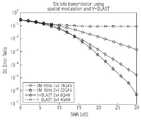
도 9는 OFDM 반송파 개수에 따른 채널 이득을 나타내는 도면이고, 도 10은 SM-OFDM에서 SM 4 X 4 16-QAM, SM 2 X 4 32-QAM, V-BLAST 2 X 4 8-QAM 및 V-BLAST 3 X 4 4-QAM V-BLAST의 SNR 별 BER을 비교하여 나타내는 도면이다.FIG. 9 is a diagram illustrating channel gain according to the number of OFDM carriers. FIG. 10 is a diagram of SM 4
도 10를 참조하여 각 OFDM의 성능을 비교하면, SM-OFDM은
2 X 4 32-QAM SM-OFDM은 SNR < 16 dB인 2 X 4 8-QAM V-BLAST-OFDM과 성능이 거의 같고, 약 2 dB 정도로 약간 성능이 좋다. 더 나아가, 2 X 4 SM 32QAM은 4 X 4 QAM 16QAM 및 3 X 4 V-BLAST-OFDM 4QAM보다 훨씬 좋은 성능을 보여준다. 3 X 4 4QAM V-BLAST-OFDM의 결과는 가장 나쁜 성능을 보인다. 도 10의 시뮬레이션 결과는 본 발명에 따른 SM 과 OFDM의 결합이 SNR 별 BER에 매우 효과적임을 보여준다.The 2
4. 수신 장치 복잡도 측정4. Receiving device complexity measurement
이하, 수신 장치의 복잡도를 종래 V-BLAST와 본 발명에 따른 SSM, SM을 비교한다. 본 발명은 기존의 V-BLAST 알고리즘보다 수신 장치의 복조 복잡도가 감소된다.Hereinafter, the complexity of the receiving apparatus is compared with the conventional V-BLAST and the SSM and SM according to the present invention. The present invention reduces the demodulation complexity of the receiving device over the conventional V-BLAST algorithm.
복잡도의 고려대상으로 소수의 곱셈과 덧셈을 고려하여 비교한다. R-SVD(singular value decomposition)를 이용한

의사역행렬(pseudoinverse)


MMSE 복잡도 계산도 유사하게 계산된다. 역행렬 계산을 위해 가우시안 소거법을 사용하면 다음과 같은 <수학식 16>에 의해 복소 연산의 총 개수를 구할 수 있다.MMSE complexity calculations are similarly calculated. If the Gaussian elimination method is used for inverse matrix calculation, the total number of complex operations can be obtained by Equation 16 as follows.

MRC는


다음에서는

OFDM 전송에 있어서, SM-OFDM에서 ZF 검출을 이용할 때 복소 연산의 횟수는

4 X 4 16-QAM SM-OFDM은 V-BLAST-OFDM과 비교하여 복소 연산의 높은 횟수를 요구한다. 그러나 2 X 4 32-QAM SM-OFDM은 V-BLAST-OFDM 보다 26.44%정도 경감된 복조 복잡도를 보여준다. 표 2 및 표 3은 본 발명에 따른 SM과 OFDM의 결합이 수신 장치에서 OFDM 복조 복잡도를 경감시키는데 효율적으로 사용될 수 있음을 보여준다.4
한편, 본 발명의 상세한 설명에서는 구체적인 실시예에 관해 설명하였으나, 본 발명의 범위에서 벗어나지 않는 한도 내에서 여러 가지로 변형될 수 있음은 물론이다. 첨부된 도면은 본 발명의 실시예를 적용하는 경우를 예시적으로 보여준 것이며, 본 발명은 전술한 실시예에 한정되는 것이 아니다. 그러므로 본 발명의 범위는 설명된 실시예에 국한되어서는 아니 되며 후술하는 특허청구범위뿐만 아니라 이 특허청구범위와 균등한 것들에 의해 정해져야 한다.On the other hand, in the detailed description of the present invention has been described with respect to specific embodiments, it can be modified in various ways without departing from the scope of the invention. The accompanying drawings show an example of applying an embodiment of the present invention, the present invention is not limited to the above-described embodiment. Therefore, the scope of the present invention should not be limited to the described embodiments, but should be defined not only by the claims below, but also by those equivalent to the claims.
본 발명은 다중입출력시스템에서 하나의 송신 안테나 만을 활성화 함으로써, 송신 안테나의 동기화가 필요 없어지고, 수신 장치에서 채널간 간섭을 제거하면서도, 안테나의 공간적 배치를 정보로 이용하여 단위 헤르츠당 전송 효율이 높일 수 있는 효과가 있다.The present invention eliminates the need for synchronization of transmission antennas by activating only one transmission antenna in a multiple input / output system, and improves transmission efficiency per unit hertz by using spatial arrangement of antennas as information while eliminating interference between channels in a receiving apparatus. It can be effective.
또한, 본 발명은 MIMO-OFDM 시스템에서 SM방법을 사용함으로써 공간 다중화 이득을 얻을 수 있으면서도 수신단의 복조 복잡도를 줄일 수 있는 효과도 있다.In addition, the present invention has an effect of reducing the demodulation complexity of the receiver while obtaining a spatial multiplexing gain by using the SM method in the MIMO-OFDM system.
Claims (29)
Translated fromKorean


Priority Applications (2)
| Application Number | Priority Date | Filing Date | Title |
|---|---|---|---|
| KR1020060064934AKR101009774B1 (en) | 2006-07-11 | 2006-07-11 | Spatial Modulation in Multiple Input and Output Systems and Transceivers Using the Same |
| US11/822,872US8094743B2 (en) | 2006-07-11 | 2007-07-10 | Spatial modulation method and transmitting and receiving apparatuses using the same in a multiple input multiple output system |
Applications Claiming Priority (1)
| Application Number | Priority Date | Filing Date | Title |
|---|---|---|---|
| KR1020060064934AKR101009774B1 (en) | 2006-07-11 | 2006-07-11 | Spatial Modulation in Multiple Input and Output Systems and Transceivers Using the Same |
Publications (2)
| Publication Number | Publication Date |
|---|---|
| KR20080006148A KR20080006148A (en) | 2008-01-16 |
| KR101009774B1true KR101009774B1 (en) | 2011-01-19 |
Family
ID=39050754
Family Applications (1)
| Application Number | Title | Priority Date | Filing Date |
|---|---|---|---|
| KR1020060064934AExpired - Fee RelatedKR101009774B1 (en) | 2006-07-11 | 2006-07-11 | Spatial Modulation in Multiple Input and Output Systems and Transceivers Using the Same |
Country Status (2)
| Country | Link |
|---|---|
| US (1) | US8094743B2 (en) |
| KR (1) | KR101009774B1 (en) |
Cited By (1)
| Publication number | Priority date | Publication date | Assignee | Title |
|---|---|---|---|---|
| KR102179642B1 (en) | 2019-05-16 | 2020-11-17 | 금오공과대학교 산학협력단 | Transmit and receive modulators |
Families Citing this family (37)
| Publication number | Priority date | Publication date | Assignee | Title |
|---|---|---|---|---|
| US8385470B2 (en) | 2000-12-05 | 2013-02-26 | Google Inc. | Coding a signal with a shuffled-Hadamard function |
| US8374218B2 (en) | 2000-12-05 | 2013-02-12 | Google Inc. | Combining signals with a shuffled-hadamard function |
| US8494459B2 (en)* | 2007-02-05 | 2013-07-23 | Nec Laboratories America, Inc. | Wideband codebook construction and applications |
| KR101040605B1 (en)* | 2009-02-27 | 2011-06-10 | 연세대학교 산학협력단 | Spatial modulation method and apparatus, and Spatial modulation method and apparatus |
| CN102099696B (en)* | 2009-05-29 | 2014-03-12 | 松下电器产业株式会社 | Antenna evaluation device and antenna evaluation method |
| KR101040606B1 (en)* | 2009-12-30 | 2011-06-10 | 연세대학교 산학협력단 | Apparatus and method for restoring a spatially modulated signal |
| US9976001B2 (en) | 2010-02-10 | 2018-05-22 | Nippon Shokubai Co., Ltd. | Process for producing water-absorbing resin powder |
| GB2478005B (en) | 2010-02-23 | 2017-06-14 | Univ Court Univ Of Edinburgh | Enhanced spatial modulation |
| US9137788B2 (en)* | 2011-09-05 | 2015-09-15 | Nec Laboratories America, Inc. | Multiple-input multiple-output wireless communications with full duplex radios |
| GB2496379A (en) | 2011-11-04 | 2013-05-15 | Univ Edinburgh | A freespace optical communication system which exploits the rolling shutter mechanism of a CMOS camera |
| WO2013107219A1 (en)* | 2012-01-21 | 2013-07-25 | Zte Corporation | Cooperative Multi-Point Modulation (CoMP-M): Method and Apparatus using Base Station Modulation with Cooperative Multi-point Transmitting and Receiving in a Cellular System |
| CN104081814A (en)* | 2012-01-21 | 2014-10-01 | 中兴通讯股份有限公司 | Coordinated Multipoint Modulation (CoMP-M): Method and Apparatus for Coordinated Multipoint Transmission and Reception Using Base Station Modulation in Cellular Systems |
| GB2501507B (en) | 2012-04-25 | 2014-09-24 | Toshiba Res Europ Ltd | Wireless communication methods and apparatus |
| CN102790747B (en)* | 2012-08-09 | 2015-01-07 | 电子科技大学 | Mapping method for spacial modulation system |
| US8953712B2 (en)* | 2012-08-27 | 2015-02-10 | Industrial Technology Research Institute | Method for data modulation and transmitter using the same |
| KR102000439B1 (en) | 2013-03-07 | 2019-07-16 | 한국전자통신연구원 | Antenna swtiching apparatus of spatial modulation |
| US9313076B2 (en)* | 2013-07-11 | 2016-04-12 | Industrial Technology Research Institute | Antenna modulation method applicable to wireless transmitter and transmitter using the same |
| US10171137B2 (en)* | 2013-08-22 | 2019-01-01 | Lg Electronics Inc. | Method and device for transmitting data by using spatial modulation scheme in wireless access system |
| EP3058688A4 (en) | 2013-10-16 | 2017-06-28 | Empire Technology Development LLC | Signal sequence estimation |
| US9813278B1 (en)* | 2013-10-31 | 2017-11-07 | Sensor Networks And Cellular System Center, University Of Tabuk | Quadrature spatial modulation system |
| RU2673874C1 (en) | 2014-12-11 | 2018-11-30 | Хуавэй Текнолоджиз Ко., Лтд. | Method of transmitting data, device of transmitting side and device of reception side |
| US10476729B2 (en)* | 2015-02-04 | 2019-11-12 | Lg Electronics Inc. | Method and apparatus for spatial modulation based on virtual antenna |
| KR101599190B1 (en)* | 2015-03-19 | 2016-03-04 | 전북대학교산학협력단 | MIMO Communication Method and System using the Block Circulant Jacket Matrices |
| US9935737B2 (en)* | 2015-06-24 | 2018-04-03 | Intel IP Corporation | Access point (AP), user station (STA) and method for spatial modulation orthogonal frequency division multiplexing (SM-OFDM) communication |
| US9819527B2 (en)* | 2015-07-02 | 2017-11-14 | Intel IP Corporation | Transmitter for spatial modulation in a high-efficiency wireless local-area network |
| JP6552051B2 (en)* | 2015-12-09 | 2019-07-31 | 株式会社日立国際電気 | Wireless communication system |
| US20170288933A1 (en)* | 2016-03-30 | 2017-10-05 | Intel IP Corporation | Wireless signal receiver |
| CN106130615A (en)* | 2016-07-27 | 2016-11-16 | 南京理工大学 | The activation antenna of generalized spatial modulation system and modulation symbol combined estimation method |
| CN107979396A (en) | 2016-10-25 | 2018-05-01 | 索尼公司 | Communicator and method for Multi-User Dimension modulation |
| TWI618374B (en)* | 2017-04-21 | 2018-03-11 | 國立臺灣大學 | Beamforming index space modulation method |
| CN107493123B (en)* | 2017-08-09 | 2020-09-29 | 重庆邮电大学 | Low-complexity detection method based on precoding-assisted generalized orthogonal spatial modulation |
| US10873373B2 (en) | 2018-03-16 | 2020-12-22 | Huawei Technologies Co., Ltd. | Simplified detection for spatial modulation and space-time block coding with antenna selection |
| CN109361637B (en)* | 2018-12-03 | 2020-09-08 | 西安电子科技大学 | Orthogonal spatial coding modulation system and method for high-dimensional signal transmission |
| CN109547077B (en)* | 2019-01-22 | 2020-10-13 | 重庆京东方智慧电子系统有限公司 | Signal transmission method, signal reception method, communication device, and storage medium |
| CN112929057A (en)* | 2021-01-22 | 2021-06-08 | 广东培正学院 | Dual generalized spatial modulation method and system |
| CN116633734B (en)* | 2023-06-26 | 2024-02-23 | 安徽大学 | SVD precoding method of super Nyquist system suitable for high-order modulation |
| CN119383051B (en)* | 2024-09-26 | 2025-08-29 | 广州商学院 | Spatial modulation method based on switch index symbol set design |
Citations (4)
| Publication number | Priority date | Publication date | Assignee | Title |
|---|---|---|---|---|
| KR20040077576A (en)* | 2003-02-28 | 2004-09-04 | 엔이씨 래버러터리즈 아메리카 인코포레이티드 | Near-optimal multiple-input multiple-output(mimo) channel detection via sequential monte carlo |
| US20050113042A1 (en) | 2003-11-20 | 2005-05-26 | Telefonaktiebolaget Lm Ericsson (Publ) | Multi-dimensional joint searcher and channel estimators |
| KR20050090230A (en)* | 2004-03-08 | 2005-09-13 | 삼성전자주식회사 | Method for decisionalling detection order in a mobile communication system |
| KR20060042523A (en)* | 2004-11-09 | 2006-05-15 | 삼성전자주식회사 | A Method for Supporting Multiple Multiple Antenna Technologies in a Broadband Wireless Access System Using Multiple Antennas |
Family Cites Families (8)
| Publication number | Priority date | Publication date | Assignee | Title |
|---|---|---|---|---|
| US7505788B1 (en)* | 2002-12-09 | 2009-03-17 | Marvell International, Ltd. | Spatial multiplexing with antenna and constellation selection for correlated MIMO fading channels |
| KR100526511B1 (en)* | 2003-01-23 | 2005-11-08 | 삼성전자주식회사 | Apparatus for transmitting/receiving pilot sequence in mobile communication system using space-time trellis code and method thereof |
| US20050113141A1 (en)* | 2003-11-20 | 2005-05-26 | Telefonaktiebolaget Lm Ericsson (Publ) | Spatial joint searcher and channel estimators |
| US20060018247A1 (en)* | 2004-07-22 | 2006-01-26 | Bas Driesen | Method and apparatus for space interleaved communication in a multiple antenna communication system |
| US8780957B2 (en)* | 2005-01-14 | 2014-07-15 | Qualcomm Incorporated | Optimal weights for MMSE space-time equalizer of multicode CDMA system |
| KR101124338B1 (en)* | 2005-07-06 | 2012-03-16 | 더 유니버시티 코트 오브 더 유니버시티 오브 에딘버그 | Mimo-based data transmission method |
| US7796702B2 (en)* | 2005-07-27 | 2010-09-14 | Interdigital Technology Corporation | Coded antenna switching for wireless communications and associated methods |
| US7657244B2 (en)* | 2005-10-27 | 2010-02-02 | Samsung Electronics Co., Ltd. | Methods of antenna selection for downlink MIMO-OFDM transmission over spatial correlated channels |
- 2006
- 2006-07-11KRKR1020060064934Apatent/KR101009774B1/ennot_activeExpired - Fee Related
- 2007
- 2007-07-10USUS11/822,872patent/US8094743B2/enactiveActive
Patent Citations (4)
| Publication number | Priority date | Publication date | Assignee | Title |
|---|---|---|---|---|
| KR20040077576A (en)* | 2003-02-28 | 2004-09-04 | 엔이씨 래버러터리즈 아메리카 인코포레이티드 | Near-optimal multiple-input multiple-output(mimo) channel detection via sequential monte carlo |
| US20050113042A1 (en) | 2003-11-20 | 2005-05-26 | Telefonaktiebolaget Lm Ericsson (Publ) | Multi-dimensional joint searcher and channel estimators |
| KR20050090230A (en)* | 2004-03-08 | 2005-09-13 | 삼성전자주식회사 | Method for decisionalling detection order in a mobile communication system |
| KR20060042523A (en)* | 2004-11-09 | 2006-05-15 | 삼성전자주식회사 | A Method for Supporting Multiple Multiple Antenna Technologies in a Broadband Wireless Access System Using Multiple Antennas |
Cited By (1)
| Publication number | Priority date | Publication date | Assignee | Title |
|---|---|---|---|---|
| KR102179642B1 (en) | 2019-05-16 | 2020-11-17 | 금오공과대학교 산학협력단 | Transmit and receive modulators |
Also Published As
| Publication number | Publication date |
|---|---|
| US8094743B2 (en) | 2012-01-10 |
| KR20080006148A (en) | 2008-01-16 |
| US20080037673A1 (en) | 2008-02-14 |
Similar Documents
| Publication | Publication Date | Title |
|---|---|---|
| KR101009774B1 (en) | Spatial Modulation in Multiple Input and Output Systems and Transceivers Using the Same | |
| CN201045756Y (en) | Transmitter and receiver for implementing space-time processing using asymmetrical modulation and encoding strategy | |
| US8107563B2 (en) | Receiving apparatus and method for MIMO system | |
| US20080187066A1 (en) | Detection method and apparatus for a multi-stream MIMO | |
| JP2008503150A (en) | Apparatus and method for encoding / decoding frequency space block code in orthogonal frequency division multiplexing system | |
| KR20050040059A (en) | Ici cancellation method in ofdm system | |
| JP2007504690A (en) | OFDM channel estimation and tracking of multiple transmit antennas | |
| CN107317612B (en) | Transmission device, reception device, transmission method, reception method, and communication system | |
| US8379748B2 (en) | Apparatus and method for reception in multi-input multi-output system | |
| Kim et al. | STBC/SFBC for 4 transmit antennas with 1-bit feedback | |
| Le Saux et al. | Iterative channel estimation based on linear regression for a MIMO-OFDM system | |
| JP2009518924A (en) | System, apparatus and method for performing spatial multiplexing by symbol diffusion | |
| Kushwah et al. | Performance Estimation of 2* 2 MIMO-MC-CDMA Using Convolution Code in Different Modulation Technique | |
| Akhtar et al. | A Comprehensive Performance Analysis of MIMO-OFDM Technology Using Different MIMO Configurations and M-QAM Modulation Schemes for LTE Cellular Network | |
| Sugiyama et al. | Development of a novel SDM-COFDM prototype for broadband wireless access systems | |
| KR101225649B1 (en) | Apparatus and method for channel estimation in multiple antenna communication system | |
| Ma et al. | An adaptive approach to estimation and compensation of frequency-dependent I/Q imbalances in MIMO-OFDM systems | |
| Hou et al. | Channel estimation improvement for MIMO single-carrier block transmission system | |
| Lorphichian et al. | Performance analysis of space diversity for OFDM transmission | |
| Narasimhan et al. | Digital baseband compensation for mobile SFBC-OFDM systems with receiver I/Q imbalance | |
| CN116915548A (en) | Equalization method and system for multiple-input multiple-output channels | |
| KR101019172B1 (en) | Apparatus and method for transmitting / receiving data in a communication system using U-BSLAT OPM system | |
| KR100828466B1 (en) | Broadcast Transmission Using Spatial Spread in Multi-antenna Communication Systems | |
| CN101371481B (en) | Method and apparatus for space-time processing using asymmetric modulation and coding schemes | |
| Rao et al. | Overhead optimization in a MIMO-OFDM testbed based on MMSE MIMO decoding |
Legal Events
| Date | Code | Title | Description |
|---|---|---|---|
| PA0109 | Patent application | St.27 status event code:A-0-1-A10-A12-nap-PA0109 | |
| PG1501 | Laying open of application | St.27 status event code:A-1-1-Q10-Q12-nap-PG1501 | |
| P11-X000 | Amendment of application requested | St.27 status event code:A-2-2-P10-P11-nap-X000 | |
| P13-X000 | Application amended | St.27 status event code:A-2-2-P10-P13-nap-X000 | |
| A201 | Request for examination | ||
| PA0201 | Request for examination | St.27 status event code:A-1-2-D10-D11-exm-PA0201 | |
| PN2301 | Change of applicant | St.27 status event code:A-3-3-R10-R13-asn-PN2301 St.27 status event code:A-3-3-R10-R11-asn-PN2301 | |
| D13-X000 | Search requested | St.27 status event code:A-1-2-D10-D13-srh-X000 | |
| D14-X000 | Search report completed | St.27 status event code:A-1-2-D10-D14-srh-X000 | |
| E902 | Notification of reason for refusal | ||
| PE0902 | Notice of grounds for rejection | St.27 status event code:A-1-2-D10-D21-exm-PE0902 | |
| P11-X000 | Amendment of application requested | St.27 status event code:A-2-2-P10-P11-nap-X000 | |
| P13-X000 | Application amended | St.27 status event code:A-2-2-P10-P13-nap-X000 | |
| E701 | Decision to grant or registration of patent right | ||
| PE0701 | Decision of registration | St.27 status event code:A-1-2-D10-D22-exm-PE0701 | |
| GRNT | Written decision to grant | ||
| PR0701 | Registration of establishment | St.27 status event code:A-2-4-F10-F11-exm-PR0701 | |
| PR1002 | Payment of registration fee | St.27 status event code:A-2-2-U10-U11-oth-PR1002 Fee payment year number:1 | |
| PG1601 | Publication of registration | St.27 status event code:A-4-4-Q10-Q13-nap-PG1601 | |
| R18-X000 | Changes to party contact information recorded | St.27 status event code:A-5-5-R10-R18-oth-X000 | |
| FPAY | Annual fee payment | Payment date:20131217 Year of fee payment:4 | |
| PR1001 | Payment of annual fee | St.27 status event code:A-4-4-U10-U11-oth-PR1001 Fee payment year number:4 | |
| LAPS | Lapse due to unpaid annual fee | ||
| PC1903 | Unpaid annual fee | St.27 status event code:A-4-4-U10-U13-oth-PC1903 Not in force date:20150114 Payment event data comment text:Termination Category : DEFAULT_OF_REGISTRATION_FEE | |
| PC1903 | Unpaid annual fee | St.27 status event code:N-4-6-H10-H13-oth-PC1903 Ip right cessation event data comment text:Termination Category : DEFAULT_OF_REGISTRATION_FEE Not in force date:20150114 |