KR101009485B1 - Universal charging device - Google Patents
Universal charging deviceDownload PDFInfo
- Publication number
- KR101009485B1 KR101009485B1KR1020100036317AKR20100036317AKR101009485B1KR 101009485 B1KR101009485 B1KR 101009485B1KR 1020100036317 AKR1020100036317 AKR 1020100036317AKR 20100036317 AKR20100036317 AKR 20100036317AKR 101009485 B1KR101009485 B1KR 101009485B1
- Authority
- KR
- South Korea
- Prior art keywords
- charging
- power
- unit
- pack
- output
- Prior art date
- Legal status (The legal status is an assumption and is not a legal conclusion. Google has not performed a legal analysis and makes no representation as to the accuracy of the status listed.)
- Active
Links
Images


Classifications
- B—PERFORMING OPERATIONS; TRANSPORTING
- B60—VEHICLES IN GENERAL
- B60L—PROPULSION OF ELECTRICALLY-PROPELLED VEHICLES; SUPPLYING ELECTRIC POWER FOR AUXILIARY EQUIPMENT OF ELECTRICALLY-PROPELLED VEHICLES; ELECTRODYNAMIC BRAKE SYSTEMS FOR VEHICLES IN GENERAL; MAGNETIC SUSPENSION OR LEVITATION FOR VEHICLES; MONITORING OPERATING VARIABLES OF ELECTRICALLY-PROPELLED VEHICLES; ELECTRIC SAFETY DEVICES FOR ELECTRICALLY-PROPELLED VEHICLES
- B60L53/00—Methods of charging batteries, specially adapted for electric vehicles; Charging stations or on-board charging equipment therefor; Exchange of energy storage elements in electric vehicles
- B60L53/60—Monitoring or controlling charging stations
- B60L53/67—Controlling two or more charging stations
- B—PERFORMING OPERATIONS; TRANSPORTING
- B60—VEHICLES IN GENERAL
- B60L—PROPULSION OF ELECTRICALLY-PROPELLED VEHICLES; SUPPLYING ELECTRIC POWER FOR AUXILIARY EQUIPMENT OF ELECTRICALLY-PROPELLED VEHICLES; ELECTRODYNAMIC BRAKE SYSTEMS FOR VEHICLES IN GENERAL; MAGNETIC SUSPENSION OR LEVITATION FOR VEHICLES; MONITORING OPERATING VARIABLES OF ELECTRICALLY-PROPELLED VEHICLES; ELECTRIC SAFETY DEVICES FOR ELECTRICALLY-PROPELLED VEHICLES
- B60L3/00—Electric devices on electrically-propelled vehicles for safety purposes; Monitoring operating variables, e.g. speed, deceleration or energy consumption
- B60L3/0023—Detecting, eliminating, remedying or compensating for drive train abnormalities, e.g. failures within the drive train
- B60L3/003—Detecting, eliminating, remedying or compensating for drive train abnormalities, e.g. failures within the drive train relating to inverters
- B—PERFORMING OPERATIONS; TRANSPORTING
- B60—VEHICLES IN GENERAL
- B60L—PROPULSION OF ELECTRICALLY-PROPELLED VEHICLES; SUPPLYING ELECTRIC POWER FOR AUXILIARY EQUIPMENT OF ELECTRICALLY-PROPELLED VEHICLES; ELECTRODYNAMIC BRAKE SYSTEMS FOR VEHICLES IN GENERAL; MAGNETIC SUSPENSION OR LEVITATION FOR VEHICLES; MONITORING OPERATING VARIABLES OF ELECTRICALLY-PROPELLED VEHICLES; ELECTRIC SAFETY DEVICES FOR ELECTRICALLY-PROPELLED VEHICLES
- B60L53/00—Methods of charging batteries, specially adapted for electric vehicles; Charging stations or on-board charging equipment therefor; Exchange of energy storage elements in electric vehicles
- B60L53/10—Methods of charging batteries, specially adapted for electric vehicles; Charging stations or on-board charging equipment therefor; Exchange of energy storage elements in electric vehicles characterised by the energy transfer between the charging station and the vehicle
- B60L53/11—DC charging controlled by the charging station, e.g. mode 4
- B—PERFORMING OPERATIONS; TRANSPORTING
- B60—VEHICLES IN GENERAL
- B60L—PROPULSION OF ELECTRICALLY-PROPELLED VEHICLES; SUPPLYING ELECTRIC POWER FOR AUXILIARY EQUIPMENT OF ELECTRICALLY-PROPELLED VEHICLES; ELECTRODYNAMIC BRAKE SYSTEMS FOR VEHICLES IN GENERAL; MAGNETIC SUSPENSION OR LEVITATION FOR VEHICLES; MONITORING OPERATING VARIABLES OF ELECTRICALLY-PROPELLED VEHICLES; ELECTRIC SAFETY DEVICES FOR ELECTRICALLY-PROPELLED VEHICLES
- B60L53/00—Methods of charging batteries, specially adapted for electric vehicles; Charging stations or on-board charging equipment therefor; Exchange of energy storage elements in electric vehicles
- B60L53/10—Methods of charging batteries, specially adapted for electric vehicles; Charging stations or on-board charging equipment therefor; Exchange of energy storage elements in electric vehicles characterised by the energy transfer between the charging station and the vehicle
- B60L53/14—Conductive energy transfer
- B60L53/16—Connectors, e.g. plugs or sockets, specially adapted for charging electric vehicles
- B—PERFORMING OPERATIONS; TRANSPORTING
- B60—VEHICLES IN GENERAL
- B60L—PROPULSION OF ELECTRICALLY-PROPELLED VEHICLES; SUPPLYING ELECTRIC POWER FOR AUXILIARY EQUIPMENT OF ELECTRICALLY-PROPELLED VEHICLES; ELECTRODYNAMIC BRAKE SYSTEMS FOR VEHICLES IN GENERAL; MAGNETIC SUSPENSION OR LEVITATION FOR VEHICLES; MONITORING OPERATING VARIABLES OF ELECTRICALLY-PROPELLED VEHICLES; ELECTRIC SAFETY DEVICES FOR ELECTRICALLY-PROPELLED VEHICLES
- B60L53/00—Methods of charging batteries, specially adapted for electric vehicles; Charging stations or on-board charging equipment therefor; Exchange of energy storage elements in electric vehicles
- B60L53/30—Constructional details of charging stations
- B60L53/305—Communication interfaces
- B—PERFORMING OPERATIONS; TRANSPORTING
- B60—VEHICLES IN GENERAL
- B60L—PROPULSION OF ELECTRICALLY-PROPELLED VEHICLES; SUPPLYING ELECTRIC POWER FOR AUXILIARY EQUIPMENT OF ELECTRICALLY-PROPELLED VEHICLES; ELECTRODYNAMIC BRAKE SYSTEMS FOR VEHICLES IN GENERAL; MAGNETIC SUSPENSION OR LEVITATION FOR VEHICLES; MONITORING OPERATING VARIABLES OF ELECTRICALLY-PROPELLED VEHICLES; ELECTRIC SAFETY DEVICES FOR ELECTRICALLY-PROPELLED VEHICLES
- B60L53/00—Methods of charging batteries, specially adapted for electric vehicles; Charging stations or on-board charging equipment therefor; Exchange of energy storage elements in electric vehicles
- B60L53/60—Monitoring or controlling charging stations
- B60L53/65—Monitoring or controlling charging stations involving identification of vehicles or their battery types
- B—PERFORMING OPERATIONS; TRANSPORTING
- B60—VEHICLES IN GENERAL
- B60L—PROPULSION OF ELECTRICALLY-PROPELLED VEHICLES; SUPPLYING ELECTRIC POWER FOR AUXILIARY EQUIPMENT OF ELECTRICALLY-PROPELLED VEHICLES; ELECTRODYNAMIC BRAKE SYSTEMS FOR VEHICLES IN GENERAL; MAGNETIC SUSPENSION OR LEVITATION FOR VEHICLES; MONITORING OPERATING VARIABLES OF ELECTRICALLY-PROPELLED VEHICLES; ELECTRIC SAFETY DEVICES FOR ELECTRICALLY-PROPELLED VEHICLES
- B60L53/00—Methods of charging batteries, specially adapted for electric vehicles; Charging stations or on-board charging equipment therefor; Exchange of energy storage elements in electric vehicles
- B60L53/60—Monitoring or controlling charging stations
- B60L53/66—Data transfer between charging stations and vehicles
- B60L53/665—Methods related to measuring, billing or payment
- B—PERFORMING OPERATIONS; TRANSPORTING
- B60—VEHICLES IN GENERAL
- B60L—PROPULSION OF ELECTRICALLY-PROPELLED VEHICLES; SUPPLYING ELECTRIC POWER FOR AUXILIARY EQUIPMENT OF ELECTRICALLY-PROPELLED VEHICLES; ELECTRODYNAMIC BRAKE SYSTEMS FOR VEHICLES IN GENERAL; MAGNETIC SUSPENSION OR LEVITATION FOR VEHICLES; MONITORING OPERATING VARIABLES OF ELECTRICALLY-PROPELLED VEHICLES; ELECTRIC SAFETY DEVICES FOR ELECTRICALLY-PROPELLED VEHICLES
- B60L53/00—Methods of charging batteries, specially adapted for electric vehicles; Charging stations or on-board charging equipment therefor; Exchange of energy storage elements in electric vehicles
- B60L53/60—Monitoring or controlling charging stations
- B60L53/68—Off-site monitoring or control, e.g. remote control
- H—ELECTRICITY
- H02—GENERATION; CONVERSION OR DISTRIBUTION OF ELECTRIC POWER
- H02J—CIRCUIT ARRANGEMENTS OR SYSTEMS FOR SUPPLYING OR DISTRIBUTING ELECTRIC POWER; SYSTEMS FOR STORING ELECTRIC ENERGY
- H02J5/00—Circuit arrangements for transfer of electric power between AC networks and DC networks
- H—ELECTRICITY
- H02—GENERATION; CONVERSION OR DISTRIBUTION OF ELECTRIC POWER
- H02J—CIRCUIT ARRANGEMENTS OR SYSTEMS FOR SUPPLYING OR DISTRIBUTING ELECTRIC POWER; SYSTEMS FOR STORING ELECTRIC ENERGY
- H02J7/00—Circuit arrangements for charging or depolarising batteries or for supplying loads from batteries
- H02J7/00032—Circuit arrangements for charging or depolarising batteries or for supplying loads from batteries characterised by data exchange
- H02J7/00034—Charger exchanging data with an electronic device, i.e. telephone, whose internal battery is under charge
- H—ELECTRICITY
- H02—GENERATION; CONVERSION OR DISTRIBUTION OF ELECTRIC POWER
- H02J—CIRCUIT ARRANGEMENTS OR SYSTEMS FOR SUPPLYING OR DISTRIBUTING ELECTRIC POWER; SYSTEMS FOR STORING ELECTRIC ENERGY
- H02J7/00—Circuit arrangements for charging or depolarising batteries or for supplying loads from batteries
- H02J7/0042—Circuit arrangements for charging or depolarising batteries or for supplying loads from batteries characterised by the mechanical construction
- H—ELECTRICITY
- H02—GENERATION; CONVERSION OR DISTRIBUTION OF ELECTRIC POWER
- H02J—CIRCUIT ARRANGEMENTS OR SYSTEMS FOR SUPPLYING OR DISTRIBUTING ELECTRIC POWER; SYSTEMS FOR STORING ELECTRIC ENERGY
- H02J7/00—Circuit arrangements for charging or depolarising batteries or for supplying loads from batteries
- H02J7/0047—Circuit arrangements for charging or depolarising batteries or for supplying loads from batteries with monitoring or indicating devices or circuits
- H—ELECTRICITY
- H02—GENERATION; CONVERSION OR DISTRIBUTION OF ELECTRIC POWER
- H02J—CIRCUIT ARRANGEMENTS OR SYSTEMS FOR SUPPLYING OR DISTRIBUTING ELECTRIC POWER; SYSTEMS FOR STORING ELECTRIC ENERGY
- H02J7/00—Circuit arrangements for charging or depolarising batteries or for supplying loads from batteries
- H02J7/02—Circuit arrangements for charging or depolarising batteries or for supplying loads from batteries for charging batteries from AC mains by converters
- B—PERFORMING OPERATIONS; TRANSPORTING
- B60—VEHICLES IN GENERAL
- B60L—PROPULSION OF ELECTRICALLY-PROPELLED VEHICLES; SUPPLYING ELECTRIC POWER FOR AUXILIARY EQUIPMENT OF ELECTRICALLY-PROPELLED VEHICLES; ELECTRODYNAMIC BRAKE SYSTEMS FOR VEHICLES IN GENERAL; MAGNETIC SUSPENSION OR LEVITATION FOR VEHICLES; MONITORING OPERATING VARIABLES OF ELECTRICALLY-PROPELLED VEHICLES; ELECTRIC SAFETY DEVICES FOR ELECTRICALLY-PROPELLED VEHICLES
- B60L2200/00—Type of vehicles
- B60L2200/36—Vehicles designed to transport cargo, e.g. trucks
- B—PERFORMING OPERATIONS; TRANSPORTING
- B60—VEHICLES IN GENERAL
- B60L—PROPULSION OF ELECTRICALLY-PROPELLED VEHICLES; SUPPLYING ELECTRIC POWER FOR AUXILIARY EQUIPMENT OF ELECTRICALLY-PROPELLED VEHICLES; ELECTRODYNAMIC BRAKE SYSTEMS FOR VEHICLES IN GENERAL; MAGNETIC SUSPENSION OR LEVITATION FOR VEHICLES; MONITORING OPERATING VARIABLES OF ELECTRICALLY-PROPELLED VEHICLES; ELECTRIC SAFETY DEVICES FOR ELECTRICALLY-PROPELLED VEHICLES
- B60L2200/00—Type of vehicles
- B60L2200/40—Working vehicles
- B60L2200/42—Fork lift trucks
- B—PERFORMING OPERATIONS; TRANSPORTING
- B60—VEHICLES IN GENERAL
- B60L—PROPULSION OF ELECTRICALLY-PROPELLED VEHICLES; SUPPLYING ELECTRIC POWER FOR AUXILIARY EQUIPMENT OF ELECTRICALLY-PROPELLED VEHICLES; ELECTRODYNAMIC BRAKE SYSTEMS FOR VEHICLES IN GENERAL; MAGNETIC SUSPENSION OR LEVITATION FOR VEHICLES; MONITORING OPERATING VARIABLES OF ELECTRICALLY-PROPELLED VEHICLES; ELECTRIC SAFETY DEVICES FOR ELECTRICALLY-PROPELLED VEHICLES
- B60L2210/00—Converter types
- B60L2210/10—DC to DC converters
- B—PERFORMING OPERATIONS; TRANSPORTING
- B60—VEHICLES IN GENERAL
- B60L—PROPULSION OF ELECTRICALLY-PROPELLED VEHICLES; SUPPLYING ELECTRIC POWER FOR AUXILIARY EQUIPMENT OF ELECTRICALLY-PROPELLED VEHICLES; ELECTRODYNAMIC BRAKE SYSTEMS FOR VEHICLES IN GENERAL; MAGNETIC SUSPENSION OR LEVITATION FOR VEHICLES; MONITORING OPERATING VARIABLES OF ELECTRICALLY-PROPELLED VEHICLES; ELECTRIC SAFETY DEVICES FOR ELECTRICALLY-PROPELLED VEHICLES
- B60L2210/00—Converter types
- B60L2210/20—AC to AC converters
- B—PERFORMING OPERATIONS; TRANSPORTING
- B60—VEHICLES IN GENERAL
- B60L—PROPULSION OF ELECTRICALLY-PROPELLED VEHICLES; SUPPLYING ELECTRIC POWER FOR AUXILIARY EQUIPMENT OF ELECTRICALLY-PROPELLED VEHICLES; ELECTRODYNAMIC BRAKE SYSTEMS FOR VEHICLES IN GENERAL; MAGNETIC SUSPENSION OR LEVITATION FOR VEHICLES; MONITORING OPERATING VARIABLES OF ELECTRICALLY-PROPELLED VEHICLES; ELECTRIC SAFETY DEVICES FOR ELECTRICALLY-PROPELLED VEHICLES
- B60L2210/00—Converter types
- B60L2210/30—AC to DC converters
- B—PERFORMING OPERATIONS; TRANSPORTING
- B60—VEHICLES IN GENERAL
- B60L—PROPULSION OF ELECTRICALLY-PROPELLED VEHICLES; SUPPLYING ELECTRIC POWER FOR AUXILIARY EQUIPMENT OF ELECTRICALLY-PROPELLED VEHICLES; ELECTRODYNAMIC BRAKE SYSTEMS FOR VEHICLES IN GENERAL; MAGNETIC SUSPENSION OR LEVITATION FOR VEHICLES; MONITORING OPERATING VARIABLES OF ELECTRICALLY-PROPELLED VEHICLES; ELECTRIC SAFETY DEVICES FOR ELECTRICALLY-PROPELLED VEHICLES
- B60L2210/00—Converter types
- B60L2210/40—DC to AC converters
- B—PERFORMING OPERATIONS; TRANSPORTING
- B60—VEHICLES IN GENERAL
- B60L—PROPULSION OF ELECTRICALLY-PROPELLED VEHICLES; SUPPLYING ELECTRIC POWER FOR AUXILIARY EQUIPMENT OF ELECTRICALLY-PROPELLED VEHICLES; ELECTRODYNAMIC BRAKE SYSTEMS FOR VEHICLES IN GENERAL; MAGNETIC SUSPENSION OR LEVITATION FOR VEHICLES; MONITORING OPERATING VARIABLES OF ELECTRICALLY-PROPELLED VEHICLES; ELECTRIC SAFETY DEVICES FOR ELECTRICALLY-PROPELLED VEHICLES
- B60L2240/00—Control parameters of input or output; Target parameters
- B60L2240/10—Vehicle control parameters
- B60L2240/36—Temperature of vehicle components or parts
- Y—GENERAL TAGGING OF NEW TECHNOLOGICAL DEVELOPMENTS; GENERAL TAGGING OF CROSS-SECTIONAL TECHNOLOGIES SPANNING OVER SEVERAL SECTIONS OF THE IPC; TECHNICAL SUBJECTS COVERED BY FORMER USPC CROSS-REFERENCE ART COLLECTIONS [XRACs] AND DIGESTS
- Y02—TECHNOLOGIES OR APPLICATIONS FOR MITIGATION OR ADAPTATION AGAINST CLIMATE CHANGE
- Y02P—CLIMATE CHANGE MITIGATION TECHNOLOGIES IN THE PRODUCTION OR PROCESSING OF GOODS
- Y02P90/00—Enabling technologies with a potential contribution to greenhouse gas [GHG] emissions mitigation
- Y02P90/60—Electric or hybrid propulsion means for production processes
- Y—GENERAL TAGGING OF NEW TECHNOLOGICAL DEVELOPMENTS; GENERAL TAGGING OF CROSS-SECTIONAL TECHNOLOGIES SPANNING OVER SEVERAL SECTIONS OF THE IPC; TECHNICAL SUBJECTS COVERED BY FORMER USPC CROSS-REFERENCE ART COLLECTIONS [XRACs] AND DIGESTS
- Y02—TECHNOLOGIES OR APPLICATIONS FOR MITIGATION OR ADAPTATION AGAINST CLIMATE CHANGE
- Y02T—CLIMATE CHANGE MITIGATION TECHNOLOGIES RELATED TO TRANSPORTATION
- Y02T10/00—Road transport of goods or passengers
- Y02T10/60—Other road transportation technologies with climate change mitigation effect
- Y02T10/70—Energy storage systems for electromobility, e.g. batteries
- Y—GENERAL TAGGING OF NEW TECHNOLOGICAL DEVELOPMENTS; GENERAL TAGGING OF CROSS-SECTIONAL TECHNOLOGIES SPANNING OVER SEVERAL SECTIONS OF THE IPC; TECHNICAL SUBJECTS COVERED BY FORMER USPC CROSS-REFERENCE ART COLLECTIONS [XRACs] AND DIGESTS
- Y02—TECHNOLOGIES OR APPLICATIONS FOR MITIGATION OR ADAPTATION AGAINST CLIMATE CHANGE
- Y02T—CLIMATE CHANGE MITIGATION TECHNOLOGIES RELATED TO TRANSPORTATION
- Y02T10/00—Road transport of goods or passengers
- Y02T10/60—Other road transportation technologies with climate change mitigation effect
- Y02T10/7072—Electromobility specific charging systems or methods for batteries, ultracapacitors, supercapacitors or double-layer capacitors
- Y—GENERAL TAGGING OF NEW TECHNOLOGICAL DEVELOPMENTS; GENERAL TAGGING OF CROSS-SECTIONAL TECHNOLOGIES SPANNING OVER SEVERAL SECTIONS OF THE IPC; TECHNICAL SUBJECTS COVERED BY FORMER USPC CROSS-REFERENCE ART COLLECTIONS [XRACs] AND DIGESTS
- Y02—TECHNOLOGIES OR APPLICATIONS FOR MITIGATION OR ADAPTATION AGAINST CLIMATE CHANGE
- Y02T—CLIMATE CHANGE MITIGATION TECHNOLOGIES RELATED TO TRANSPORTATION
- Y02T10/00—Road transport of goods or passengers
- Y02T10/60—Other road transportation technologies with climate change mitigation effect
- Y02T10/72—Electric energy management in electromobility
- Y—GENERAL TAGGING OF NEW TECHNOLOGICAL DEVELOPMENTS; GENERAL TAGGING OF CROSS-SECTIONAL TECHNOLOGIES SPANNING OVER SEVERAL SECTIONS OF THE IPC; TECHNICAL SUBJECTS COVERED BY FORMER USPC CROSS-REFERENCE ART COLLECTIONS [XRACs] AND DIGESTS
- Y02—TECHNOLOGIES OR APPLICATIONS FOR MITIGATION OR ADAPTATION AGAINST CLIMATE CHANGE
- Y02T—CLIMATE CHANGE MITIGATION TECHNOLOGIES RELATED TO TRANSPORTATION
- Y02T90/00—Enabling technologies or technologies with a potential or indirect contribution to GHG emissions mitigation
- Y02T90/10—Technologies relating to charging of electric vehicles
- Y02T90/12—Electric charging stations
- Y—GENERAL TAGGING OF NEW TECHNOLOGICAL DEVELOPMENTS; GENERAL TAGGING OF CROSS-SECTIONAL TECHNOLOGIES SPANNING OVER SEVERAL SECTIONS OF THE IPC; TECHNICAL SUBJECTS COVERED BY FORMER USPC CROSS-REFERENCE ART COLLECTIONS [XRACs] AND DIGESTS
- Y02—TECHNOLOGIES OR APPLICATIONS FOR MITIGATION OR ADAPTATION AGAINST CLIMATE CHANGE
- Y02T—CLIMATE CHANGE MITIGATION TECHNOLOGIES RELATED TO TRANSPORTATION
- Y02T90/00—Enabling technologies or technologies with a potential or indirect contribution to GHG emissions mitigation
- Y02T90/10—Technologies relating to charging of electric vehicles
- Y02T90/14—Plug-in electric vehicles
- Y—GENERAL TAGGING OF NEW TECHNOLOGICAL DEVELOPMENTS; GENERAL TAGGING OF CROSS-SECTIONAL TECHNOLOGIES SPANNING OVER SEVERAL SECTIONS OF THE IPC; TECHNICAL SUBJECTS COVERED BY FORMER USPC CROSS-REFERENCE ART COLLECTIONS [XRACs] AND DIGESTS
- Y02—TECHNOLOGIES OR APPLICATIONS FOR MITIGATION OR ADAPTATION AGAINST CLIMATE CHANGE
- Y02T—CLIMATE CHANGE MITIGATION TECHNOLOGIES RELATED TO TRANSPORTATION
- Y02T90/00—Enabling technologies or technologies with a potential or indirect contribution to GHG emissions mitigation
- Y02T90/10—Technologies relating to charging of electric vehicles
- Y02T90/16—Information or communication technologies improving the operation of electric vehicles
- Y02T90/167—Systems integrating technologies related to power network operation and communication or information technologies for supporting the interoperability of electric or hybrid vehicles, i.e. smartgrids as interface for battery charging of electric vehicles [EV] or hybrid vehicles [HEV]
- Y—GENERAL TAGGING OF NEW TECHNOLOGICAL DEVELOPMENTS; GENERAL TAGGING OF CROSS-SECTIONAL TECHNOLOGIES SPANNING OVER SEVERAL SECTIONS OF THE IPC; TECHNICAL SUBJECTS COVERED BY FORMER USPC CROSS-REFERENCE ART COLLECTIONS [XRACs] AND DIGESTS
- Y04—INFORMATION OR COMMUNICATION TECHNOLOGIES HAVING AN IMPACT ON OTHER TECHNOLOGY AREAS
- Y04S—SYSTEMS INTEGRATING TECHNOLOGIES RELATED TO POWER NETWORK OPERATION, COMMUNICATION OR INFORMATION TECHNOLOGIES FOR IMPROVING THE ELECTRICAL POWER GENERATION, TRANSMISSION, DISTRIBUTION, MANAGEMENT OR USAGE, i.e. SMART GRIDS
- Y04S30/00—Systems supporting specific end-user applications in the sector of transportation
- Y04S30/10—Systems supporting the interoperability of electric or hybrid vehicles
- Y04S30/14—Details associated with the interoperability, e.g. vehicle recognition, authentication, identification or billing
Landscapes
- Engineering & Computer Science (AREA)
- Power Engineering (AREA)
- Transportation (AREA)
- Mechanical Engineering (AREA)
- Life Sciences & Earth Sciences (AREA)
- Sustainable Development (AREA)
- Sustainable Energy (AREA)
- Charge And Discharge Circuits For Batteries Or The Like (AREA)
- Secondary Cells (AREA)
- Electric Propulsion And Braking For Vehicles (AREA)
Abstract
Translated fromKoreanDescription
Translated fromKorean본 발명은 전기 자동차, 전기 카트, 전동 지게차 등을 포함한 전기 차량을 충전시키는 유니버셜 충전 장치에 관한 것이다.
The present invention relates to a universal charging device for charging an electric vehicle, including electric vehicles, electric carts, electric forklifts and the like.
전기 차량(EV : Electronic Vehicle)에는 EV 배터리가 설치되며, 배터리 제어 시스템으로서 BMS(Battery Management System)가 설치된다.An EV battery is installed in an electric vehicle (EV), and a battery management system (BMS) is installed as a battery control system.
현재, 녹색 기술 개발의 일환으로서 전기 차량에 관한 연구는 물론 전기 차량의 활용성을 높이기 위하여 전기 차량의 충전 시스템에 관한 많은 연구가 행해지고 있다. 그러나, 아직까지는 개발 진행 단계에 불과하여 해결해야 하는 기술적 문제는 물론 다양한 소비자 욕구에 부합되는 충전 시스템이 보급화되지 못하고 있다.Currently, as part of the development of green technology, a lot of researches are being conducted on electric vehicle charging systems in order to improve the utilization of electric vehicles as well as electric vehicles. However, the charging system that meets a variety of consumer needs as well as technical problems to be solved only to the development progress stage so far has not been popularized.
전기 차량의 활성화를 위하여, 우선, 화석 연료 자동차의 주유소와 유사한 형태를 갖는 충전 시스템이 널리 보급됨으로써 주유소의 운영 체계와 사용 방법이 유사하게 적용될 수 있는 충전 시스템이 개발되어야 한다.In order to activate an electric vehicle, first, a charging system having a form similar to a gas station of a fossil fuel vehicle has been widely spread, and a charging system in which the operating system and a method of use of a gas station can be similarly applied must be developed.
그리고, 주유소의 연료 탱크가 대형으로 설치되고 전력값 증설이 가능한 것과 같이 충전 시스템도 대형화될 필요가 있으며 그 전력값 증설이 용이한 구조로 설치될 필요가 있다.And, as the fuel tank of the gas station is installed in a large size and the power value can be increased, the charging system needs to be enlarged, and the power value needs to be installed in an easy structure.
또한, 주유소의 주유 시간에 비하여 전기 차량의 충전 시간은 무척 긴 편이므로 급속 충전이 필요한 사용자에게는 비용 추가에 불구하고 짧은 시간에 충전할 수 있어야 한다. 반면에 충전 비용에 관심이 있는 사용자에게는 적은 비용으로 완속 충전도 겸할 수 있어야 한다.In addition, since the charging time of the electric vehicle is very long compared to the fueling time of the gas station, users who need rapid charging should be able to charge in a short time despite the additional cost. On the other hand, users who are interested in charging costs should be able to combine slow charging at low cost.
한편, 급속 충전 모드 뿐만 아니라 버스나 트럭 등의 대용량 전기 차량도 즉각 충전 가능해야 한다. 따라서, 충전 속도 및 충전 용량을 유연성있게 변경할 수 있도록 DC 전원을 대용량으로 출력할 수 있는 충전 시스템이 설치되어야 하고 차량의 종류를 파악할 수 있는 BMS 데이터에 따라 충전 전력값의 변동이 매우 쉽게 이루어질 수 있는 제어 수단이 마련되어야 한다.Meanwhile, not only a quick charging mode but also a large-capacity electric vehicle such as a bus or a truck should be able to be charged immediately. Therefore, a charging system capable of outputting a large amount of DC power must be installed to flexibly change the charging speed and the charging capacity, and the variation of the charging power value can be made very easily according to the BMS data that can identify the type of vehicle. Control means should be provided.
더 나아가, 유류 저장 탱크의 설치를 위하여 기존의 주유소와 같이 넓은 장소가 요구되는 것은 아니므로, 편의점이나 슈퍼마켓과 같이 좁은 장소에서도 설치 가능한 크기 가변이 용이한 충전 시스템을 개발할 필요가 있다.Furthermore, since the installation of the oil storage tank does not require a wide place like an existing gas station, it is necessary to develop a filling system that can be easily changed in size, even in a narrow place such as a convenience store or a supermarket.
그리고, 충전 수단이 대형화되고 유지 보수의 유연성 확보를 위하여 간단한 구조로 이루어지고 전기 사고 방지를 위한 방수 대책이나 안전 사고를 원천 차단할 수 있는 충전 시스템이 개발되어야 한다.
In addition, a charging system has to be developed to have a simple structure in order to increase the charging means and to secure the flexibility of maintenance, and to prevent waterproof accidents or safety accidents to be prevented.
본 발명은 상술한 필요성을 감안한 것으로서, 충전 장치의 설치가 매우 용이하고, 급속 충전 및 대형 차량의 충전이 가능하도록 필요시에 출력 전력값을 신속하게 증가시킬 수 있으며, 전기 안전 사고를 미연에 방지할 수 있는 구조로 되어 있고, 편의점이나 수퍼마켓과 같은 일반적인 생활 공간에서 작은 크기로 설치 가능하며, 전기 차량의 상태나 충전 장치의 상태를 자동으로 감지하여 충전 모드를 최적으로 자동 제어할 수 있는 유니버셜 충전 장치를 제공하기 위한 것이다.
SUMMARY OF THE INVENTION The present invention has been made in view of the above-mentioned necessity, and the installation of a charging device is very easy, and the output power value can be quickly increased when necessary to enable rapid charging and charging of a large vehicle, and prevent electrical safety accidents. It can be installed in a small size in a common living space such as a convenience store or a supermarket, and can automatically control the charging mode by automatically detecting the state of an electric vehicle or the state of a charging device. It is for providing a charging device.
일 실시예로서, 본 발명의 유니버셜 충전 장치는, AC 전원이 입력되는 AC 터미널과, 상기 AC 전원을 DC 전원으로 정류하는 AC/DC 변환기와, 제1 전력값의 DC 전원을 출력하는 DC 터미널과, 상기 DC 전원의 출력을 온/오프시키는 충전팩 스위치가 마련되는 충전팩; 을 포함하고, 상기 충전팩이 복수로 설치되며 서로 병렬 연결되고, 상기 충전팩의 설치 개수의 증감 또는 상기 각 충전팩 스위치의 온/오프 여부에 따라, 상기 제1 전력값부터 상기 제1 전력값의 양의 정수 배에 해당하는 다양한 전력값의 DC 전원을 출력하며, 상기 DC 전원의 전력값 변화에 따라 전기 차량의 충전 속도 조절이 가능하다.
In one embodiment, the universal charging device of the present invention, an AC terminal to which AC power is input, an AC / DC converter for rectifying the AC power source into a DC power source, and a DC terminal outputting a DC power source having a first power value; A charging pack provided with a charging pack switch for turning on / off an output of the DC power supply; Includes a plurality of the charge pack is installed in parallel and connected to each other, depending on whether the increase or decrease of the number of installation of the charge pack or the on / off of each of the charge pack switch, the amount of the first power value from the first power value Outputs a DC power of various power values corresponding to an integer multiple, it is possible to adjust the charging speed of the electric vehicle according to the power value change of the DC power.
일 실시예로서, 본 발명의 유니버셜 충전 장치는, 제1 전력값의 DC 전원을 생성하는 충전팩이 제1 충전팩부터 제n 충전팩까지 병렬로 배열되며, 상기 n은 양의 정수인 충전 모듈; 상기 충전 모듈이 제1 충전 모듈부터 제k 충전 모듈까지 착탈 가능하게 병렬로 배열되며, 상기 k는 양의 정수인 충전 유니트; 전기 차량의 내부에 설치되는 EV 배터리 및 BMS와 연결되는 복수의 커넥터와, 상기 커넥터를 통한 충전량을 표시하는 표시부가 마련되는 충전대; 데이터 통신을 통하여 입수한 상기 충전팩, 상기 충전 모듈, 상기 충전 유니트, 상기 충전대 및 상기 BMS의 설치 개수 또는 작동 상태에 따라, 상기 충전팩의 제1 전력값부터 상기 제1 전력값의 양의 정수 배에 해당하는 다양한 전력값의 DC 전원을 상기 커넥터별로 구분 공급하는 메인 제어부; 를 포함한다.
In one embodiment, the universal charging device of the present invention, the charging pack for generating a DC power supply of the first power value is arranged in parallel from the first charging pack to the n-th charging pack, wherein n is a positive integer; The charging modules are arranged in a detachable parallel manner from the first charging module to the kth charging module, wherein k is a positive integer; A charging table provided with a plurality of connectors connected to the EV battery and the BMS installed in the electric vehicle, and a display unit for displaying the charging amount through the connector; According to the installed number or operating state of the charging pack, the charging module, the charging unit, the charging station and the BMS obtained through data communication, the first power value of the charging pack is multiplied by a positive integer multiple of the first power value. A main controller for separately supplying DC power having various power values to each connector; It includes.
일 실시예로서, 본 발명의 유니버셜 충전 장치는, 전기 차량의 내부에 설치되는 EV 배터리 및 BMS와 연결되는 복수의 커넥터와, 상기 커넥터를 통한 충전량을 표시하는 표시부가 마련되는 충전대; 상기 충전대에 DC 전원을 공급하는 충전 유니트; 를 포함하며, 상기 충전 유니트는 상기 충전대와 별개로 마련되며 서로 다른 위치에 설치된다.
In one embodiment, the universal charging device of the present invention, the charging unit is provided with a plurality of connectors connected to the EV battery and the BMS installed inside the electric vehicle, and a display unit for displaying the charge amount through the connector; A charging unit for supplying DC power to the charging station; It includes, The charging unit is provided separately from the charging stand and are installed in different positions.
일 실시예로서, 본 발명의 유니버셜 충전 장치는, 충전 모듈이 제1 충전 모듈부터 제k 충전 모듈까지 착탈 가능하게 병렬로 배열되는 충전 유니트; 전기 차량의 내부에 설치되는 EV 배터리 및 BMS와 연결되는 복수의 커넥터와, 상기 커넥터를 통한 충전량을 표시하는 표시부가 마련되는 충전대; 상기 충전 모듈, 상기 충전 유니트, 상기 충전대 및 상기 BMS의 설치 개수 또는 작동 상태를 데이터 통신을 통하여 입수하고, 상기 충전 모듈 한 개가 출력하는 DC 전원의 전력값부터 여기에 상기 양의 정수 k를 곱한 전력값까지 변동 가능한 다양한 전력값의 DC 전원을 급속 충전 또는 완속 충전 여부에 따라 상기 커넥터별로 구분 공급하는 메인 제어부; 를 포함한다.In one embodiment, the universal charging device of the present invention, the charging module is a charging unit that is detachably arranged in parallel from the first charging module to the k-th charging module; A charging table provided with a plurality of connectors connected to the EV battery and the BMS installed in the electric vehicle, and a display unit for displaying the charging amount through the connector; The installed number or operating state of the charging module, the charging unit, the charging station and the BMS is obtained through data communication, and the power is multiplied by the positive integer k from the power value of the DC power output by one charging module. A main control unit for supplying DC power of various power values that can be changed to a value according to the connector according to whether fast charging or slow charging is performed; It includes.
일 실시예로서, 본 발명의 유니버셜 충전 장치는, 제1 전력값의 DC 전원을 생성하는 충전팩이 복수개 병렬로 배열된 충전 모듈; 상기 충전 모듈이 제1 충전 모듈부터 제k 충전 모듈까지 착탈 가능하게 병렬로 배열되는 충전 유니트; 전기 차량의 내부에 설치되는 EV 배터리 및 BMS와 연결되는 복수의 커넥터와, 상기 커넥터를 통한 충전량을 표시하는 표시부가 마련되는 충전대; 상기 충전팩, 상기 충전 모듈, 상기 충전 유니트, 상기 충전대 및 상기 BMS의 설치 개수 또는 작동 상태를 데이터 통신을 통하여 입수하고, 상기 충전팩 한 개가 출력하는 상기 제1 전력값부터 상기 제1 전력값에 상기 충전팩의 배열 개수 및 상기 양의 정수 k를 곱한 전력값까지 변동 가능한 다양한 전력값의 DC 전원을 급속 충전 또는 완속 충전 여부에 따라 상기 커넥터별로 구분 공급하는 메인 제어부; 를 포함한다.
In one embodiment, the universal charging device of the present invention, the charging module for generating a DC power supply of the first power value a plurality of charging modules arranged in parallel; A charging unit in which the charging modules are detachably arranged in parallel from the first charging module to the k-th charging module; A charging table provided with a plurality of connectors connected to the EV battery and the BMS installed in the electric vehicle, and a display unit for displaying the charging amount through the connector; The installed number or operating state of the charging pack, the charging module, the charging unit, the charging station, and the BMS is obtained through data communication, and the charging pack is configured to the first power value from the first power value output by one of the charging packs. A main control unit for supplying DC power of various power values that can be varied up to the power value multiplied by the arrangement number and the positive integer k for each connector according to whether fast charging or slow charging is performed; It includes.
본 발명에 따르면, 충전팩, 충전 모듈, 충전 유니트에 이르는 다단의 블럭 구조를 통하여 손쉽게 출력 전력값의 확장 및 변경을 달성할 수 있으며, 이와 같은 충전 유니트의 멀티 구조에 의하여 충전 장치의 대용량화 및 충전 속도 조절에 즉각 대응할 수 있고, 커넥터별로 서로 다른 전력값, 서로 다른 전압, 서로 다른 전류를 내보낼 수 있으므로 전기 차량의 BMS에서 읽어들인 데이터나 충전대를 통하여 입수한 사용자 지령에 알맞은 최적의 전력값, 전압 및 전류로써 전기 차량을 지능적으로 충전할 수 있고, 충전 유니트가 충전대와 분리형으로 설치 가능하므로 충전 시스템의 설치 유연성이 확보되며, 각각의 충전팩과 커넥터의 연결을 다양한 연결 수단에 의하여 메쉬 구조로 변동 가능하게 구성할 수 있으므로 각 커넥터 별로 전력값, 전압, 전류의 가변이 손쉽게 이루어지는 장점을 갖는다.
According to the present invention, it is possible to easily expand and change the output power value through a multi-stage block structure ranging from a charging pack, a charging module, and a charging unit, and to increase the capacity and charging speed of the charging device by the multi-structure of the charging unit. It can respond immediately to adjustments, and can emit different power values, different voltages, and different currents for each connector, so that the optimum power value, voltage and The electric vehicle can be charged intelligently by the electric current, and the charging unit can be installed separately from the charging stand to secure the installation flexibility of the charging system, and the connection of each charging pack and the connector can be changed into the mesh structure by various connecting means. Since it is possible to configure the power value, voltage, and current of each connector This has the advantage of easily made.
도 1은 본 발명의 충전팩의 일 실시예를 도시한 블럭도이다.
도 2는 본 발명의 충전 모듈의 일 실시예를 도시한 블럭도이다.
도 3은 본 발명의 충전 유니트의 일 실시예를 도시한 블럭도이다.
도 4는 본 발명의 충전 장치의 일 실시예를 도시한 블럭도이다.
도 5는 본 발명의 충전 장치의 다른 일 실시예를 도시한 블럭도이다.
도 6은 도 5의 실시예를 개략적으로 시각화한 그림이다.
도 7은 본 발명의 충전 모듈의 다른 일 실시예를 도시한 블럭도이다.
도 8은 도 7의 실시예에서 DC 출력부 및 복수의 DC 버스바를 상세하게 도시한 블럭도이다.
도 9는 도 7 및 도 8의 실시예를 적용한 본 발명의 충전 장치의 다른 일 실시예를 도시한 블럭도이다.
도 10은 본 발명에서 DC 전원 전력값의 가변 구성을 설명하기 위한 설명도이다.
도 11 내지 도 14는 본 발명의 유니버셜 충전 장치의 다양한 구성 및 그에 따른 작용을 설명하는 개념도이다.1 is a block diagram showing an embodiment of a charging pack of the present invention.
2 is a block diagram showing an embodiment of a charging module of the present invention.
3 is a block diagram showing an embodiment of a charging unit of the present invention.
4 is a block diagram showing an embodiment of a charging device of the present invention.
5 is a block diagram showing another embodiment of the charging device of the present invention.
6 is a schematic visualization of the embodiment of FIG. 5.
7 is a block diagram showing another embodiment of the charging module of the present invention.
FIG. 8 is a detailed block diagram illustrating a DC output unit and a plurality of DC busbars in the embodiment of FIG. 7.
9 is a block diagram showing another embodiment of the charging device of the present invention to which the embodiments of FIGS. 7 and 8 are applied.
10 is an explanatory diagram for explaining a variable configuration of a DC power supply value in the present invention.
11 to 14 are conceptual views illustrating various configurations and operations according to the universal charging device of the present invention.
이하, 첨부된 도면을 참조하여 본 발명에 따른 실시예를 상세히 설명한다. 이 과정에서 도면에 도시된 구성요소의 크기나 형상 등은 설명의 명료성과 편의상 과장되게 도시될 수 있다. 또한, 본 발명의 구성 및 작용을 고려하여 특별히 정의된 용어들은 사용자, 운용자의 의도 또는 관례에 따라 달라질 수 있다. 이러한 용어들에 대한 정의는 본 명세서 전반에 걸친 내용을 토대로 내려져야 한다.Hereinafter, exemplary embodiments of the present invention will be described in detail with reference to the accompanying drawings. In this process, the size or shape of the components shown in the drawings may be exaggerated for clarity and convenience of description. In addition, terms that are specifically defined in consideration of the configuration and operation of the present invention may vary depending on the intention or custom of the user or operator. Definitions of these terms should be made based on the contents throughout the specification.
도 1은 본 발명의 충전팩(100)의 일 실시예를 도시한 블럭도이다. 도 2는 본 발명의 충전 모듈(200)의 일 실시예를 도시한 블럭도이다. 도 3은 본 발명의 충전 유니트(300)의 일 실시예를 도시한 블럭도이다.1 is a block diagram showing an embodiment of a
도 1 내지 도 3을 함께 참조하면, 본 발명의 충전 장치는 충전팩(100), 충전 모듈(200), 충전 유니트(300)를 포함한다. 따라서, 충전 수단으로서 간단한 AC/DC 변환 회로로 이루어진 충전팩(100)을 기본 블럭으로 하고, 이러한 기본 블럭을 벽돌을 쌓듯이 적층하여 충전 모듈(200) 또는 충전 유니트(300)를 구성하므로 이론상으로는 무한대의 전력값을 갖도록 간단하게 증설 가능한 구조로 되어 있다.1 to 3 together, the charging device of the present invention includes a
본 발명의 충전 유니트(300)는 일반적인 배터리와 달리 미리 충전된 직류 전원을 출력하는 축전지 기능을 하는 것이 아니며, 간단히 표현하면 교류 입력 전원을 직류로 변환 출력하는 AD/DC 변환 수단에 해당한다. 또한, 본 발명의 충전 유니트(300)는 다단의 블럭 구조로 되어 있으므로, 단지 블럭 구조의 적층에 의하여 대전력값의 DC 전원 출력을 얻을 수 있으며, 단일 블럭으로 대전력값의 DC 전원을 변활할 때 요구되는 높은 안정성의 복잡한 변환 회로가 필요하지 않으며, 다양한 전력값을 출력하기 위하여 각 전력값별로 구별되는 회로 설계가 불필요하며, 전력값 변경 작업을 메인 제어부(500)의 제어 동작을 통하여 자동으로 쉽게 구현할 수 있다.Unlike the general battery, the
따라서, 본 발명의 충전 장치는, 범용 부품을 사용하여 간단한 회로 구성을 갖는 충전팩(100)을 기본 블럭으로 삼아, 이를 적층하여 또 다른 개념의 블럭인 충전 모듈(200)을 구성하고, 충전 모듈(200)을 적층하여 충전 유니트(300)를 구성하는 등, 각각의 단위 블럭을 적층하는 개념으로 된 것이 주요 특징 중 하나이다.Therefore, the charging device of the present invention, using the general-purpose components, the
충전팩(100)은 AC 터미널(110)과, AC/DC 변환기(114)와, DC 터미널(120)과, 충전팩 스위치(118)를 포함한다. 세부 구성으로서 퓨즈(111), 노이즈 필터(112), 전류 제한기(113), 출력 필터(115), 피드백 수단(116), 구동 칩(117), 전압 검출부(119), DC/DC 변환기(130), 충전팩 배터리(140)를 더 포함할 수 있다.The
AC 터미널(110)은 2상 또는 3상의 교류 전원이 입력되는 단자이다. 교류 전원은 110 볼트부터 540볼트 등 다양한 전압이 될 수 있다. 퓨즈(111)(fuse)는 장치의 보호를 위하여 마련된다. 노이즈 필터(112)(noise filter)는 교류 입력 전원에 포함된 노이즈를 제거하기 위한 것이다. 전류 제한기(113)(Inrush current limit)는 과도한 전류 입력을 차단하여 충전팩(100)의 파손을 방지한다.The
AC/DC 변환기(114)는 AC 입력 전원을 DC 출력 전원으로 정류한다. 출력 필터(115)는 AC/DC 변환기(114)에서 출력되는 DC 출력 전원의 리플(ripple) 성분을 제거하여 평활화시킨다. AC/DC 변환기(114)는 구동 칩(117)에 의하여 제어되며, 후술하는 메인 제어부(500)의 지령에 따라 충전팩(100)의 DC 전원의 출력 전압이나 출력 전류까지 변동시킬 수 있다. DC 전원의 출력 전압 및 출력 전류의 곱은 DC 터미널(120)에서 출력되는 제1 전력값이 된다.The AC /
DC/DC 변환기(130)는 필요한 경우에 마련되며, DC 출력 전원의 전압이 정격 전압에 미치지 못할 때 이를 보상하거나, 충전팩(100)이 각 시점별로 일정한 전압을 출력하거나 출력 전압을 변동시킬 수 있도록 하거나, 충전팩(100)이 각 시점별로 일정한 전류를 출력하게 하거나, 출력 전류를 시간에 따라 변동시킬 수 있도록 하는 구성으로서, DC 출력 전원의 승압이나 감압 기능을 담당한다.The DC /
DC 터미널(120)은 AC/DC 변환기(114) 또는 DC/DC 변환기(130)에서 출력되는 DC 출력 전원을 외부로 전달하는 단자이다. 전압 검출부(119)는 DC 터미널(120)로 향하는 DC 전원 출력의 전압을 검출하여 피드백 수단(116)을 통하여 구동 칩(117)으로 전달하는 센서이다.The
따라서, 메인 제어부(500) 또는 구동 칩(117)이 AC/DC 변환기(114)의 동작을 제어함으로써, DC 터미널(120)에서 출력되는 제1 전력값의 크기를 변동시킬 수도 있다. 본 발명은 충전팩(100)에서 출력되는 제1 전력값이 상수(예를 들어 6Kw)인 경우 충전팩(100)에서 출력되는 DC 전원의 출력 전압 또는 출력 전류를 조정할 수 있음은 물론, 경우에 따라서는 구동 칩(117)으로 AC/DC 변환기(114) 또는 DC/DC 변환기(130)를 제어함으로써 제1 전력값도 가변할 수 있다.Therefore, the
일 실시예로서, 충전팩 배터리(140)는 비용이 저렴한 심야 전력을 DC 전원으로 변환하는 경우나, 온도 상승으로 인하여 충전팩(100)이 정상적인 작동을 할 수 없는 경우에, 비상 전원을 DC 터미널(120)에 출력하기 위한 것으로 필요한 경우에 설치 가능하다.In one embodiment, the
충전팩 스위치(118)는 AC/DC 변환기(114)의 동작을 온/오프시킴으로써 DC 터미널(120)에서 출력되는 DC 전원을 온/오프시킨다. 충전팩 스위치(118)가 온되면 충전팩(100)의 DC 터미널(120)에서 DC 전원이 정상적으로 출력되고, 충전팩 스위치(118)가 오프되면 DC 터미널(120)을 통한 DC 전원 출력이 차단된다.The
구동 칩(117)은 충전팩(100)의 동작을 제어하며 충전팩(100)의 온도를 감시하고 CAN 통신을 통하여 외부에서 입력된 제어 지령대로 충전팩 스위치(118)를 자동 온/오프시키는 기능을 하며, 충전팩(100) 내부에 설치된 각종 전력 부품의 동작을 제어한다.The
충전팩(100)은 가변 전압 또는 가변 전류를 출력하도록 제어될 수 있지만, 설명의 편의상, 충전팩(100)은 정전압 또는 정전류로 제어되면서 예를 들어 6Kw로 상수값을 갖는 제1 전력값의 DC 전원을 출력한다.The charging
이때, 전력값의 증설을 위하여 충전팩(100)은 복수로 설치되며 서로 병렬 연결된다. 이때, 충전팩(100)의 설치 개수의 증감 또는 각 충전팩 스위치(118)의 온/오프 여부에 따라, 충전팩(100)은 제1 전력값인 6Kw부터 상기 제1 전력값의 양의 정수 배에 해당하는 다양한 전력값(예를 들어 6Kw, 12Kw, 600Kw 등)의 DC 전원을 출력한다.At this time, in order to increase the power value, the charging
여기서, 상기 양의 정수는 충전팩 스위치(118)가 온되어 있는 충전팩(100)의 설치 개수가 될 수 있다. 예를 들어 10개의 충전팩(100)이 설치되고 10개의 충전팩 스위치(118)가 온(on)된 상태라고 하면 60Kw의 DC 전력값이 출력되므로 급속 충전 또는 대형 차량의 충전이 가능하고, 5개의 충전팩 스위치(118)만 온된 상태라고 하면 30Kw의 DC 전력값이 출력된다. 이와 같은 가변 블럭 구조를 제어함으로써 DC 전원의 전력값 변화를 달성하고, 전기 차량의 충전 속도 조절이 가능하게 된다.In this case, the positive integer may be the number of installation of the
한편, 충전팩(100)만을 여러 개 적층하여 하나의 충전 블럭을 완성하는 상기 실시예에서는 제1 전력값을 갖는 충전팩(100)의 개수 조절이나 충전팩 스위치(118)의 온/오프만으로 전력값을 쉽게 증가시킬 수 있으며, 전력값 증가가 이론상으로는 무한정 가능하고, 전력값의 가변은 충전팩(100)의 개수 조절은 물론 그 밖에도 충전팩 스위치(118)의 온/오프만으로 자동 제어할 수 있는 장점이 있다.
Meanwhile, in the above embodiment in which only one
일 실시예로서, 복수의 충전팩(100)은 충전 모듈(200)을 구성한다. 충전 모듈(200)은 복수의 충전팩(100)이 병렬 연결 상태로 배열된 것으로서, 충전 모듈(200) 단위로 AC 입력부(210)를 통하여 AC 전원을 입력받고 데이터 통신에 의하여 외부에서 동작 제어될 수 있다. 이를 위하여 충전 모듈(200)은 충전팩(100)의 배열과, AC 입력부(210)와, DC 출력부(220)와, 충전 모듈(200)의 내부 동작을 제어하는 충전 모듈 컨트롤러(217)를 포함한다.In one embodiment, the plurality of
여기서, 데이터 통신은 CAN(CONTROLLER AREA NETWORK)통신 또는 RS-232C, RS-485통신 프로토콜을 사용하는 것이 바람직하다. CAN은 1980년대에 자동차용 네트워크 프로토콜로 개발된 것으로 성능이 우수하면서도 비용이 저렴하여 ISO 11898 국제 표준으로 지정된 프로토콜이다. 특히, CAN의 높은 데이터 처리 속도, 전기적 장애에 대한 강력한 면역성과 에러를 감지하고 교정하는 능력 때문에 전기 차량과 같이 노이즈에 민감한 제어 시스템에 적합하다. CAN의 아키텍처는 하위 두 개의 물리적 계층과 데이터 링크 제어 계층에 걸쳐 정의되어 있으며, CAN_L과 CAN_N 라인을 사용하여 데이터를 입출력한다.Here, the data communication is preferably using CAN (CONTROLLER AREA NETWORK) communication or RS-232C, RS-485 communication protocol. CAN was developed as an automotive network protocol in the 1980s and has been designated as an ISO 11898 international standard due to its high performance and low cost. In particular, CAN's high data rate, its strong immunity to electrical disturbances and its ability to detect and correct errors make it ideal for noise-sensitive control systems such as electric vehicles. The architecture of CAN is defined across the lower two physical layers and the data link control layer, using the CAN_L and CAN_N lines to input and output data.
AC 입력부(210)는 각 충전팩(100)의 AC 터미널(110)에 AC 연결 라인(212)을 통하여 AC 전원을 공통 입력하고, DC 출력부(220)는 충전팩(100)의 DC 터미널(120)이 DC 연결 라인(222)을 통하여 병렬 연결되어 증가된 전력값을 출력하는 부분이다.The
충전 모듈 컨트롤러(217)는 충전팩(100)과 데이터 통신하면서 각각의 충전팩(100) 별로 충전팩 스위치(118)의 온/오프 여부를 개별 제어한다. 충전 모듈 컨트롤러(217)에 의한 각각의 충전팩 스위치(118)의 온/오프 여부에 따라 DC 출력부(220)에서 출력되는 DC 전원의 전력값이 가변된다.The
상기 실시예에서는 충전 모듈(200)을 하나의 단위로 하여 여러 개의 충전팩(100)을 동시에 운용할 수 있고, 충전 모듈 컨트롤러(217)가 각각의 충전팩 스위치(118)를 온/오프시킴으로써 각 충전팩(100)을 개별 제어할 수 있는 제어 편의성이 있다.
In the above embodiment, a plurality of charge packs 100 may be operated simultaneously using the
일 실시예로서, 복수의 충전 모듈(200)은 충전 유니트(300)를 구성한다. 충전 유니트(300)는 복수의 충전 모듈(200)이 착탈 가능하게 결합되며 이들이 서로 병렬 연결된 것이다. 충전 유니트(300)는 AC 버스바(310)와, DC 버스바(320)를 포함한다. AC 버스바(310)는 각 충전 모듈(200)의 AC 입력부(210)가 공통 연결되어 AC 전원을 입력받는 것이고, DC 버스바(320)는 각 충전 모듈(200)의 DC 출력부(220)가 병렬 연결되어 DC 전력값을 증가시켜 출력하는 것이다.In an embodiment, the plurality of charging
AC 전원은 AC 버스바(310)를 통하여 충전 유니트(300)에 입력된 다음, AC 터미널(110)을 통하여 충전 모듈(200)별로 분배되고, AC 터미널(110)을 통하여 충전팩(100)별로 공통 입력된다. DC 터미널(120)을 통하여 각 충전팩(100)에서 제1 전력값으로 출력되는 DC 전원은 DC 출력부(220) 및 DC 버스바(320)를 거치며 그 전력값이 변동된다.AC power is input to the
이러한 실시예에서, 충전 유니트(300)에 설치되는 충전 모듈(200)의 개수에 비례하여 DC 버스바(320)에서 출력되는 DC 전원의 전력값이 가변된다. 예를 들어, 10개의 충전팩(100)이 설치되고 10개의 충전팩 스위치(118)가 온된 상태의 충전 모듈(200)은 60Kw의 DC 출력을 갖고, 상기 충전 모듈(200)이 10개 연결된 충전 유니트(300)는 충전 모듈(200)의 개수에 비례하는 600Kw의 DC 출력을 갖는다.In this embodiment, the power value of the DC power output from the
여기서, 충전팩(100)이 기본 블럭이 되고, 충전팩(100)을 적층시킨 충전 모듈(200)이 또 다른 블럭으로 되며, 충전 모듈(200)을 적층시킨 충전 유니트(300)가 최종적인 충전 블럭이 된다. 그러나, 충전팩(100)을 쌓아서 충전 모듈(200)을 구성하지 않고 단일 회로로 이루어진 충전 모듈(200)(예를 들어 60Kw전력값의 AC/DC 변환기(114)를 갖는 충전 모듈(200))을 구성한 다음 이를 적층시켜 충전 유니트(300)를 완성하는 것도 본 발명의 실시예로 포함된다.
Here, the charging
도 4는 본 발명의 충전 장치의 일 실시예를 도시한 블럭도이다. 도 1 내지 도 4를 참조하면, 충전 유니트(300), 메인 제어부(500), 표시부(610), 커넥터(20a,20b,20c), 파워 전달부(400)가 일체형 스탠드(U0)형태로 설치되는 유니버셜 충전 장치가 도시된다. 커넥터(20a,20b,20c)는 각각의 전기 차량의 내부에 설치되는 EV 배터리 및 BMS와 연결되며, 커넥터 라인(15)은 DC 전원이 인가되는 전원선과 데이터가 입출력되는 신호선을 포함한다.4 is a block diagram showing an embodiment of a charging device of the present invention. 1 to 4, the charging
표시부(610)는 커넥터(20a,20b,20c)를 통한 충전량을 각각 표시한다. 파워 전달부(400)는 충전 유니트(300)에서 생성된 DC 전원을 커넥터 라인(15)을 통하여 각각의 커넥터(20a,20b,20c)에 전달한다.The
메인 제어부(500)는 충전 모듈 컨트롤러(217)가 설치된 충전 유니트(300)와 데이터 통신하면서 충전 모듈 컨트롤러(217)를 충전 모듈(200)별로 개별 제어하여 각 충전팩(100)에 설치된 충전팩 스위치(118)를 온/오프시킨다.The
한편, 도 4에 도시된 충전 장치는 전체가 일체형 스탠드(U0) 형태로 설치되므로 충전 유니트(300)의 공간 점유에 의하여 충전 장치의 설치 부피가 증가되고, 야외에 설치되는 경우 충전 유니트(300)의 방수 및 전기적 절연 문제가 대두될 수 있다.
On the other hand, since the entire charging device shown in Figure 4 is installed in the form of an integrated stand (U0), the installation volume of the charging device is increased by occupying the space of the charging
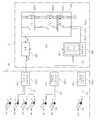
도 5는 본 발명의 충전 장치의 다른 일 실시예를 도시한 블럭도이다. 도 6은 도 5의 실시예를 개략적으로 시각화한 그림이다. 도 4에서 설명한 일체형 스탠드(U0)의 설치상의 문제점을 개선하기 위하여, 도 5 및 도 6에 도시된 실시예에서는 충전 유니트(300)와 충전대(600a,600b,600c)를 별도로 마련하고 별개의 장소에 설치한다. 즉, 충전 유니트(300), 파워 전달부(400) 및 메인 제어부(500)를 포함한 옥내부(U1)와, 충전대(600a,600b,600c) 및 커넥터(20a,20b,20c)를 포함한 옥외부(U2) 등 2개의 블럭으로 충전 장치를 구성한다.5 is a block diagram showing another embodiment of the charging device of the present invention. 6 is a schematic visualization of the embodiment of FIG. 5. In order to improve the installation problem of the integrated stand (U0) described in Figure 4, in the embodiment shown in Figures 5 and 6, the charging
예를 들어 옥내부(U1)는 설치 부피의 제약을 받지 않으며 옥내에 설치되므로 방수나 전기적 절연의 문제에서 자유롭고, 일반 주유소의 저장 탱크와 같이 지중에 매설할 수 있으므로 설치 공간이 크게 절약된다. 편의점이나 수퍼마켓에 유니버셜 충전 장치를 설치할 경우 충전 유니트(300)를 포함한 옥내부(U1)는 창고 등에 설치하고 충전대(600a,600b,600c)를 포함한 옥외부(U2)는 사람의 출입이 잦고 전기 차량의 접근성이 좋은 입구 쪽에 설치할 수 있어, 좁은 생활 공간에도 대용량의 충전 장치를 쉽게 설치할 수 있다. 서로 이격 설치되는 옥내부(U1) 및 옥외부(U2)는 전원선과 신호선을 포함한 2 종류의 연결 라인으로 연결되면, 설치 면적이나 각 장치들의 이격 거리를 얼마든지 조절할 수 있다.For example, the indoor unit U1 is not limited by the installation volume and is installed indoors, so it is free from problems of waterproofing and electrical insulation, and can be buried underground like a storage tank of a general gas station, thereby greatly saving installation space. When installing a universal charging device in a convenience store or a supermarket, the indoor unit U1 including the
충전대(600a,600b,600c)는 여러개 설치될 수 있으며, 충전 전력값, 출력 전압, 출력 전류별로 구분되는 복수의 커넥터(20a,20b,20c)가 설치될 수 있고, 충전량을 표시하는 표시부(610)가 마련되며, 사용자 지령을 입력받을 수 있다.Charging
메인 제어부(500)는, BMS, 파워 전달부(400) 및 충전 유니트(300)와 데이터 통신하고, BMS를 통하여 파악되는 전기 차량의 충전 상태, 충전팩(100)에 마련된 구동 칩(117)을 통하여 파악된 충전팩(100)의 온도 및 동작 상태, 충전 모듈 컨트롤러(217)를 통하여 파악되는 충전팩(100) 또는 충전 모듈(200)의 온도 및 동작 상태, 충전대(600a,600b,600c)에 입력된 사용자 지령 중 적어도 하나를 인식한다.The
이에 따라 메인 제어부(500)는 각각의 커넥터(20a,20b,20c)별로 다양하게 인가될 DC 전원의 전력값, 출력 전압, 출력 전류를 최적 결정한다. 예를 들어 제1 충전대(600a)에 설치된 제1 커넥터(20a)는 고전력값을 출력하여 급속 충전에 사용하고, 대형 차량이나 급속 충전 비용을 지불한 전기 차량만 접근할 수 있도록 제1 충전대(600a)를 설치한다.Accordingly, the
예를 들어 소형 전기 차량의 충전 전압은 72V이고, 전동 지게차의 충전 전압은 320V라고 가정한다. 메인 제어부(500)는 충전대(600a,600b,600c)에 입력된 차종 또는 BMS에서 읽어들인 정보에 따라 DC 전원의 출력 전압을 72V 또는 320V로 할 것인지 여부, 어느 커넥터(20a,20b,20c)에 320V를 인가할 것인지 여부, 충전 속도나 충전 대수에 따라 출력 전력값을 얼마로 증가시킬 것인지 여부 등을 결정하고, 이에 따라 충전팩(100)의 구동 칩(117), 충전 모듈(200)의 충전 모듈 컨트롤러(217), 파워 전달부(400) 등의 제어 지령을 하달한다.For example, suppose the charging voltage of a small electric vehicle is 72V, and the charging voltage of the electric forklift truck is 320V. The
제2 충전대(600b)에 설치된 제2 커넥터(20b) 및 제3 충전대(600c)에 설치된 제3 커넥터(20c)는 제1 충전대(600a)에 설치된 제1 커넥터(20a)보다 출력 전력값이 낮은 중속 또는 완속 충전용으로 이용할 수 있다.The
도 1 내지 도 6을 함께 참조하면, 충전 모듈(200)에는 6Kw로 예시된 제1 전력값의 DC 전원을 생성하는 충전팩(100)이 제1 충전팩(100a)부터 제n 충전팩(100n)까지 병렬로 배열된다. 충전 유니트(300)에는 충전 모듈(200)이 제1 충전 모듈(200a)부터 제k 충전 모듈(200k)까지 착탈 가능하게 병렬로 배열된다. 여기서, 상기 n 및 k는 양의 정수(1,2...)이다.Referring to FIGS. 1 to 6, in the
메인 제어부(500)는 데이터 통신을 통하여 입수한 충전팩(100), 충전 모듈(200), 충전 유니트(300), 충전대(600a,600b,600c) 및 BMS의 설치 개수 또는 작동 상태에 따라, 충전팩(100)의 제1 전력값(예를 들어 6Kw)부터 상기 제1 전력값의 양의 정수 배에 해당하는 다양한 전력값의 DC 전원을 커넥터(20a,20b,20c)별로 구분 공급한다.The
예를 들어 n이 10이고 k가 1인 경우 최대 60Kw 전력값을 커넥터(20a,20b,20c)에 공급할 수 있고, 충전 모듈(200)을 하나 추가하여 k가 2인 경우 최대 120Kw 전력값을 커넥터(20a,20b,20c)에 공급할 수 있다.For example, when n is 10 and k is 1, a maximum 60 Kw power value may be supplied to the
메인 제어부(500)는 충전팩(100)별로 충전팩 스위치(118)를 온/오프시켜 제1 충전팩(100a)부터 제n 충전팩(100n) 중 특정의 충전팩(100)을 선택적으로 충전대(600a,600b,600c)에 연결한다. 제1 충전팩(100a) 내지 제n 충전팩(100n) 중 특정의 충전팩을 선택하여 온시키면 DC 출력부(220)에서 출력되는 DC 전원의 전력값이 변동된다. 예를 들어 한 대의 전기 차량만 충전하며 하나의 충전팩 스위치(118)만 온되고 다른 충전팩의 충전팩 스위치(118)는 전부 오프된 경우 6Kw가 최대 출력이 된다.
The
한편, 메인 제어부(500)가 제1 충전 모듈(200a)부터 제k 충전 모듈(200k) 중 특정의 충전 모듈을 선택하여 DC 버스바(320)에 연결시키면 DC 버스바(320)에서 출력되는 DC 전원의 전력값이 변동된다. 즉, 충전 모듈(200)의 설치 개수와 같이 수동적인 제어 변수가 변화되는 것은 물론, 메인 제어부(500)에서 능동적으로 충전 모듈(200)을 선택하는 제어 동작에 의하여 DC 전력값을 변동시킬 수 있다. 뿐만 아니라, 각 커넥터(20a,20b,20c)별로 서로 다른 전력값이 출력되게 하거나, 서로 다른 전압 또는 서로 다른 전류가 출력되게 할 수 있는데 이에 대한 세부 실시예는 도 7 내지 도 9에 자세하게 도시된다.Meanwhile, when the
도 7은 본 발명의 충전 모듈(200)의 다른 일 실시예를 도시한 블럭도이다. 도 8은 도 7의 실시예에서 DC 출력부(220) 및 복수의 DC 버스바(320)를 상세하게 도시한 블럭도이다. 도 9는 도 7 및 도 8의 실시예를 적용한 본 발명의 충전 장치의 다른 일 실시예를 도시한 블럭도이다.7 is a block diagram showing another embodiment of the
도 7 내지 도 9를 함께 참조하면, DC 스위치부(229) 및 가변 릴레이부(410) 중 적어도 하나가 설치된다.7 to 9 together, at least one of the
DC 스위치부(229)는 DC 터미널(120) 중 적어도 일부를 선택하여 복수의 조합으로 병렬 연결시킨다. 이때, DC 버스바(320)는 제1 DC 버스바(320a), 제2 DC 버스바(320b), 제n DC 버스바(320n)를 포함하여 여러 가닥으로 마련되는 것이 바람직하다. 각각의 DC 버스바(320a...320n)별로 서로 다른 전력값/전압/전류를 출력하게 하거나, 각각의 커넥터(20a,20b,20c)별로 서로 다른 전력값/전압/전류가 출력되게 하기 위함이다.The
가변 릴레이부(410)는 DC 버스바(320a...320n)가 여러 가닥으로 마련될 때 DC 버스바(320a...320n) 중 적어도 일부를 선택하여 복수의 조합으로 병렬 연결시킨다.The
DC 스위치부(229)는 충전 모듈(200a..200k)의 DC 출력부(220)에 설치되며, 가변 릴레이부(410)는 DC 버스바(320a...320n)의 출측에 해당하는 파워 전달부(400)에 설치될 수 있다.The
메인 제어부(500)는, DC 스위치부(229) 또는 가변 릴레이부(410) 중 적어도 하나의 동작을 제어함으로써, 제1 충전팩(100a) 내지 제n 충전팩(100n) 중 특정의 충전팩을 선택적으로 연결하거나, 제1 충전 모듈(200a)부터 제k 충전 모듈(200k) 중 특정의 충전 모듈을 선택적으로 연결할 수 있다.
The
도 8을 참조하면, DC 스위치부(229)의 기능이 잘 설명된다. 이를 참조하면, 제1 DC 버스바(320a)에는 제1 충전팩(100a) 한 개만 연결되므로, 설명의 편의상 충전팩(100)의 제1 전력값의 예로서 들고 있는 6Kw가 최대 출력이 된다. 제2 DC 버스바(320b)에는 제2 충전팩(100b), 제3 충전팩(100c), 제4 충전팩(100d) 등 세 개의 충전팩이 연결되므로 18Kw가 최대 출력이 된다. 제n DC 버스바(320n)에는 제1 충전팩(100a) 내지 제n 충전팩(100n)이 모두 병렬 연결되고 n이 10인 경우 60Kw가 최대 출력이 된다.Referring to Fig. 8, the function of the
이때, 각각의 DC 버스바(320)에 어느 충전팩이 연결될 것이며, 몇 개의 충전팩이 연결될 것인지 여부는 고정된 것이 아니라, 메인 제어부(500) 또는 메인 제어부(500)와 데이터 통신으로 연결된 충전 모듈 컨트롤러(217)에 의하여 얼마든지 변경할 수 있다. 이를 위하여 DC 스위치부(229)에는 충전 모듈 컨트롤러(217)에 의하여 동작 제어되는 FET, 하드웨어 스위치, 다이오드 등의 조합 회로가 구성된다.At this time, which charging pack will be connected to each
즉, 충전 모듈 컨트롤러(217)에서 입력되는 지령에 따라, DC 스위치부(229)는 제1 충전팩(100a) 내지 제n 충전팩(100n) 중 선택된 충전팩과 제1 DC 버스바(320a) 내지 제n DC 버스바(320n) 중 선택된 DC 버스바를 서로 연결시킨다.That is, according to the command input from the
뿐만 아니라, DC 스위치부(229)는, 예를 들어 제1 DC 버스바(320a) 및 제1 충전 모듈(200a)의 모든 충전팩의 연결을 끊고, 제1 DC 버스바(320a) 및 제2 충전 모듈(200b)의 모든 충전팩의 연결을 끊을 수 있다. 이 경우 제1 DC 버스바(320a)를 통하여 DC 전원이 출력되지 않게 할 수 있다.In addition, the
이와 같이 충전 모듈(200)의 DC 출력부(220)에 DC 스위치부(229) 및 DC 전원 플러그(221a,221b,...221n)를 마련하고 DC 버스바(320a...320n)를 여러 가닥으로 마련하며 각각의 DC 버스바(320a...320n)마다 구별되는 DC 전원 플러그(221a,221b,...221n)를 연결하면, 각각의 DC 버스바(320a...320n)별로 서로 다른 전력값을 출력할 수 있다.As such, the
또한, 각각의 DC 버스바(320a...320n)에 서로 다른 커넥터(20a,20b,20c)가 연결되는 경우 각각의 커넥터(20a,20b,20c)별로 서로 다른 전력값을 출력할 수 있다. 이때, 메인 제어부(500)가 충전팩(100) 또는 충전 모듈(200)별로 구별되는 전압 또는 구별되는 전류를 출력하게 하면, 각각의 DC 버스바(320a...320n)나, 각각의 커넥터(20a,20b,20c)별로 서로 다른 출력 전압 또는 서로 다른 출력 전류를 갖게 할 수 있다.
In addition, when
한편, 도 9를 참조하면, 가변 릴레이부(410)의 기능이 잘 설명된다. 일 실시예로서, 가변 릴레이부(410)는 DC 버스바(320)의 출측인 파워 전달부(400)에 설치된다. 가변 릴레이부(410)는 메인 제어부(500)의 지령에 따라 제어되며, 각각의 DC 버스바(320a...320n)와 커넥터(20a,20b,20c)의 연결 상태를 가변시키는 작용을 한다.Meanwhile, referring to FIG. 9, the function of the
예를 들어 가변 릴레이부(410)가 제1 DC 버스바(320a) 내지 제n DC 버스바(320n)를 모두 제1 충전대(600a)에 연결하면 제1 충전대(600a)의 최대 전력값은 600Kw가 된다. 물론, 충전팩(100a...100n)의 제1 전력값은 6Kw이고, 각각의 충전 모듈(200a...200k)에는 10개의 충전팩(100)이 온 상태로 설치되며, 충전 모듈(200a...200k)은 모두 10개이고 이들이 전부 제1 DC 버스바(320a) 내지 제n DC 버스바(320n)에 연결된 경우를 예로 들었을 때이다.
For example, when the
도 10을 참조하며 본 발명에서 DC 전원 전력값을 가변시키는 DC 스위치부(229) 및 가변 릴레이부(410)의 기능을 더 설명한다. 이하에는 설명의 편의상, 충전팩(100a...100j)의 제1 전력값은 6Kw이고, 충전 모듈(200a...200k)에는 10개의 충전팩(100a...100j)이 충전팩 스위치(118)가 온된 상태로 배열되며, 충전 모듈(200a...200k)은 모두 10개 마련되는 것으로 가정한다. 모든 설명은 예로 드는 것 뿐이며 변형된 실시예가 얼마든지 가능하다.Referring to FIG. 10, the functions of the
도 10에 도시된 제3 커넥터(20c)의 최대 출력은 6Kw이다. 이때, DC 스위치부(229)는 제1 충전 모듈(200a)의 제1 충전팩(100a)만 제3 커넥터(20c)에 연결시키고, 다른 충전 모듈 및 다른 충전팩은 연결 차단한 상태이며, 제1 충전 모듈(200a)의 제1 충전팩(100a)만을 제1 DC 버스바(320a) 내지 제n DC 버스바(320n) 중 어느 하나에 연결시킨다. 또한, 가변 릴레이부(410)는 어느 하나의 DC 버스바를 제3 커넥터(20c)에 연결시키고 다른 DC 버스바 및 다른 커넥터의 연결은 차단한다. 따라서, 제3 커넥터(20c)에는 제1 충전 모듈(200a)의 제1 충전팩(100a)만이 하나의 DC 버스바를 통하여 연결되며, 제3 커넥터(20c)의 최대 출력은 6Kw이다.The maximum output of the
한편, 도 10에서 제2 커넥터(20b)의 최대 출력은 30Kw이다. DC 스위치부(229)는 제2 충전 모듈(200b)의 제1 충전팩(100a) 및 제2 충전팩(100b)과 제10 충전 모듈의 제1 충전팩(100a) 내지 제3 충전팩(100c)을 병렬 연결시킨다. 상기 병렬 연결은 DC 스위치부(229)의 제어 동작에 의한 DC 버스바(320)의 가닥수 및 분기 상태, 또는 가변 릴레이부(410)에 의하여 변경 가능하다.Meanwhile, in FIG. 10, the maximum output of the
일 실시예로서, 제2 커넥터(20b)에 연결된 충전팩들은 제1 DC 버스바(320a) 내지 제n DC 버스바(320n) 중 적어도 하나의 DC 버스바에 연결된다. 예를 들면, 가변 릴레이부(410)는 제2 DC 버스바(320)를 제2 커넥터(20b)에 연결시키고 다른 DC 버스바의 연결은 차단한다.In one embodiment, the charging packs connected to the
이러한 DC 스위치부(229)의 동작은 DC 스위치부(229)를 구성하는 FET, 하드웨어 스위치, 다이오드 등의 조합 회로를 메인 제어부(500) 또는 이에 종속되는 충전 모듈 컨트롤러(217)의 제어 동작에 의하여 자동 제어된다.
The operation of the
도 11 내지 도 14를 참조하며 본 발명의 유니버셜 충전 장치의 다양한 구성 및 그에 따른 작용을 예를 들어 설명한다. 설명의 편의상, 충전팩(100a,100b...100j)의 제1 전력값은 6Kw이고, 각각의 충전 모듈(200a,200b,200c)에는 10개의 충전팩(100a,100b...100j)이 배열되며, 충전 모듈(200a,200b,200c)은 1개 또는 3개 마련되는 것으로 가정한다. 도 11 내지 도 14에 DC 연결 라인(222) 또는 DC 버스바(320a,,320b,320c,...320j)의 크기가 서로 다르게 도시되어 있지만, DC 연결 라인(222) 또는 DC 버스바(320a,,320b,320c,...320j)의 실제 크기가 물리적인 의미를 갖는 것은 아니다. 각각의 충전팩(100a,100b...100j)이나 충전 모듈(200a,200b,200c)이 선택적으로 병렬 연결되면 충분하다. 도면상에서 DC 연결 라인(222) 또는 DC 버스바(320)의 크기 차이는 단지 설명의 편의를 위한 것이다.11 to 14, various configurations of the universal charging device of the present invention and the effects thereof will be described by way of example. For convenience of description, the first power value of the charge pack (100a, 100b ... 100j) is 6Kw, 10 charge pack (100a, 100b ... 100j) is arranged in each charging module (200a, 200b, 200c) It is assumed that one or three charging
도 11에는 충전 유니트에 제1 충전 모듈(200a) 1개만 설치된다. DC 스위치부(도 8 참조, 229) 및 가변 릴레이부(410)는 마련되지 않으며, DC 버스바는 1개만 마련되거나 수 개의 DC 버스바가 모두 병렬 연결된 상태이다. 충전팩 스위치(118)의 온/오프 여부는 도시된 바와 같으며, 'O'은 온(on)된 상태이고, 'X'는 오프(off)된 상태이다. 이때, 충전 유니트는 DC 연결 라인(222)을 통하여 12Kw의 최대 전력값을 출력한다.In FIG. 11, only one
도 12에는 충전 유니트에 제1 충전 모듈(200a) 내지 제3 충전 모듈(200c)이 설치된다. DC 스위치부(도 8 참조, 229) 및 가변 릴레이부(410)는 마련되지 않는다. DC 버스바(320)도 1개만 마련되며 여러 갈래로 분기되지 않는다. 충전팩 스위치(118)의 온/오프 여부는 도시된 바와 같다. 충전 유니트는 단일의 DC 버스바(320)를 통하여 30Kw의 최대 전력값을 출력한다.In FIG. 12, first to
도 13에는 충전 유니트에 제1 충전 모듈(200a) 내지 제3 충전 모듈(200c)이 설치된다. DC 스위치부(도 8 참조, 229)가 마련되며, 가변 릴레이부(410)는 설치되지 않는다. DC 버스바(320)는 3개 마련된다. DC 버스바(320)의 형상은 도시된 형상으로 한정되지 않으며, 각 DC 버스바(320)의 형상 차이는 DC 버스바(320)의 영역에 속한 충전팩(100a,100b...100j) 또는 충전 모듈(200a,200b,200c)이 서로 병렬 연결되었음을 표시하기 위한 것이다. 각 DC 버스바(320)의 형상 차이는 DC 스위치부(도 8 참조, 229)의 스위칭 동작에 따라 가변되는 것으로 이해한다. 충전팩 스위치(118)의 온/오프 여부는 도시된 바와 같다.13, the
여기서, DC 스위치부(도 8 참조, 229)는 제1 충전 모듈(200a), 제2 충전 모듈(200b) 및 제3 충전 모듈(200c) 각각에 설치된 제1 충전팩(100a)을 제1 DC 버스바(320a)에 연결시킨다. 각각의 충전팩 스위치(118)의 온/오프 여부에 따라, 충전 유니트는 제1 DC 버스바(320a)를 통하여 12Kw의 최대 전력값을 출력한다.Here, the DC switch unit (see FIG. 8, 229) is a first DC bus to the
또한, DC 스위치부(도 8 참조, 229)는 제1 충전 모듈(200a), 제2 충전 모듈(200b), 제3 충전 모듈(200c) 각각에 설치된 제2 충전팩(100b) 내지 제4 충전팩(100d)을 제2 DC 버스바(320b)에 연결시킨다. 각각의 충전팩 스위치(118)의 온/오프 여부에 따라, 충전 유니트는 제2 DC 버스바(320b)를 통하여 36Kw의 최대 전력값을 출력한다.In addition, the DC switch unit (see FIG. 8, 229) may include the
따라서, 제1 DC 버스바(320a)에 연결된 제1 커넥터(20a)는 12Kw의 최대 전력값을 출력하고, 제2 DC 버스바(320b)에 연결된 제2 커넥터(20b)는 36Kw의 최대 전력값을 출력한다.Accordingly, the
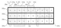
도 14에는 충전 유니트에 제1 충전 모듈(200a) 내지 제3 충전 모듈(200c)이 설치된다. DC 스위치부(도 8 참조, 229) 및 가변 릴레이부(410)가 모두 마련된다. DC 버스바(320a,...320j)는 10개 마련된다. 충전팩 스위치(118)의 온/오프 여부는 도시된 바와 같다.14, the
DC 스위치부(도 8 참조, 229)는 제1 충전 모듈(200a), 제2 충전 모듈(200b) 및 제3 충전 모듈(200c) 각각의 제4 충전팩(100d)을 제4 DC 버스바(320d)에 연결시킨다. 또한, DC 스위치부(도 8 참조, 229)는 제1 충전 모듈(200a), 제2 충전 모듈(200b) 및 제3 충전 모듈(200c)의 제5 충전팩(100e)을 제5 DC 버스바(320e)에 연결시킨다. 또한, DC 스위치부(도 8 참조, 229)는 제1 충전 모듈(200a), 제2 충전 모듈(200b) 및 제3 충전 모듈(200c) 각각의 제7 충전팩(100g)을 제7 DC 버스바(320g)에 연결시킨다. 또한, DC 스위치부(도 8 참조, 229)는 제1 충전 모듈(200a), 제2 충전 모듈(200b) 및 제3 충전 모듈(200c)의 제8 충전팩(100h)을 제8 DC 버스바(320h)에 연결시킨다. 또한, DC 스위치부(도 8 참조, 229)는 제1 충전 모듈(200a), 제2 충전 모듈(200b) 및 제3 충전 모듈(200c)의 제9 충전팩(100i)을 제9 DC 버스바(320i)에 연결시킨다.In the DC switch unit (see FIG. 8, 229), the
가변 릴레이부(410)는 제4 DC 버스바(320d), 제5 DC 버스바(320e), 제7 DC 버스바(320g), 제8 DC 버스바(320h), 제9 DC 버스바(320i)를 제1 커넥터(20a)에 연결시킨다. 10개의 충전팩이 온되었으므로, 충전 유니트는 제1 커넥터(20a)에 60Kw의 최대 전력값을 출력한다.The
또한, DC 스위치부(도 8 참조, 229)는 제1 충전 모듈(200a), 제2 충전 모듈(200b) 및 제3 충전 모듈(200c)의 제10 충전팩(100j)을 제10 DC 버스바(320j)에 연결한다. 가변 릴레이부(410)는 제10 DC 버스바(320j)를 제2 커넥터(20b)에 연결한다. 1 개의 충전팩 스위치(118)가 온되었으므로, 충전 유니트는 제2 커넥터(20b)에 6Kw의 최대 전력값을 출력한다.In addition, the DC switch unit (refer to FIG. 8, 229) may include the
따라서, 제1 커넥터(20a)는 급속 충전용으로 사용되며, 제2 커넥터(20b)는 완속 충전용으로 구분 사용된다. 여기서, 전력값 조절을 위한 병렬 연결의 자유도 변화를 살펴보면, 충전팩 스위치(118)만 설치되면 충전 유니트는 1 자유도를 갖는다. 충전팩 스위치(118) 및 DC 스위치부(도 8 참조, 229)가 설치되면 충전 유니트는 2 자유도를 가진다. 충전팩 스위치(118), DC 스위치부(도 8 참조, 229) 및 가변 릴레이부(410)가 함께 설치되면 충전 유니트는 병렬 연결 자유도가 3이다.Therefore, the
메인 제어부는 BMS를 통하여 파악되는 정보, 충전팩에 마련된 구동 칩을 통하여 파악되는 충전팩의 온도 및 동작 상태, 충전 모듈 컨트롤러를 통하여 파악되는 충전 모듈의 온도 및 동작 상태, 충전대에 입력된 사용자 지령 등을 인식한다.The main controller recognizes the information obtained through the BMS, the temperature and operating state of the charging pack determined by the driving chip provided in the charging pack, the temperature and operating state of the charging module identified through the charging module controller, and the user command input to the charging station. do.
이에 따라, 메인 제어부는, 충전팩 스위치의 온/오프 여부, DC 스위치부 및 가변 릴레이부의 메쉬 연결 구조를 결정하며, 이에 따른 제어 명령을 하달하고, 각각의 커넥터별로 인가될 DC 전원의 전력값/전압/전류 등을 최적 결정한다.Accordingly, the main controller determines whether the charge pack switch is on / off, the mesh connection structure of the DC switch unit and the variable relay unit, issues control commands accordingly, and provides the power value / voltage of the DC power to be applied for each connector. Optimally determine the current and the like.
이상에서 본 발명에 따른 실시예들이 설명되었으나, 이는 예시적인 것에 불과하며, 당해 분야에서 통상적 지식을 가진 자라면 이로부터 다양한 변형 및 균등한 범위의 실시예가 가능하다는 점을 이해할 것이다. 따라서, 본 발명의 진정한 기술적 보호 범위는 다음의 특허청구범위에 의해서 정해져야 할 것이다.
Although embodiments according to the present invention have been described above, these are merely exemplary, and it will be understood by those skilled in the art that various modifications and equivalent embodiments of the present invention are possible therefrom. Therefore, the true technical protection scope of the present invention will be defined by the following claims.
15...커넥터 라인20a,20b,20c...커넥터
100...충전팩100a...제1 충전팩
100b...제2 충전팩100n...제n 충전팩
110...AC 터미널(AC terminal)111...퓨즈
112...노이즈 필터113...전류 제한기
114...AC/DC 변환기115...출력 필터
116...피드백 수단117...구동 칩
118...충전팩 스위치119...전압 검출부
120...DC 터미널(DC terminal)130...DC/DC 변환기
140...충전팩 배터리200...충전 모듈
200a...제1 충전 모듈200b...제2 충전 모듈
200k...제k 충전 모듈210...AC 입력부
212...AC 연결 라인217...충전 모듈 컨트롤러
220...DC 출력부222...DC 연결 라인
229...DC 스위치부300...충전 유니트
310...AC 버스바320...DC 버스바
320a...제1 DC 버스바320b...제2 DC 버스바
320n....제n DC 버스바400...파워 전달부
410...가변 릴레이부500...메인 제어부
600a...제1 충전대600b...제2 충전대
600c...제3 충전대610...표시부
U0...일체형 스탠드U1...옥내부
U2...옥외부15
100 ...
100b ...
110
114 ... AC /
116.Feedback means 117 ... Drive chip
118 ...
120 ... DC terminal 130 ... DC / DC converter
140 ...
200a ... first charging
200 k ... k charging
212 ...
220 ...
310 ...
320a ...
320 n .... n
410 ...
600a ... first charging
600c ... 3rd charging
U0 ... Integrated stand U1 ... Indoor
U2 ... outdoors
Claims (20)
Translated fromKorean상기 충전팩이 복수로 배열되며 서로 병렬 연결되고,
상기 충전팩의 설치 개수의 증감 또는 상기 각 충전팩 스위치의 온/오프 여부에 따라, 상기 제1 전력값부터 상기 제1 전력값의 양의 정수 배에 해당하는 다양한 전력값으로 정류된 상기 DC 전원이 상기 충전팩의 배열로부터 전기 차량으로 공급되며,
상기 DC 전원의 전력값 변화에 따라 상기 전기 차량의 충전 속도 조절이 가능한 유니버셜 충전 장치.
An AC terminal to which AC power is input, an AC / DC converter for rectifying the AC power to DC power, a DC terminal for outputting DC power of a first power value, and a charge pack switch for turning on / off the output of the DC power Charge pack is provided; Including,
The charging pack is arranged in plurality and connected in parallel to each other,
The DC power rectified to various power values corresponding to a positive integer multiple of the first power value from the first power value according to whether the installed number of the charge pack is increased or decreased or whether each of the charge pack switches is on / off Is supplied to the electric vehicle from an array of charge packs,
Universal charging device capable of adjusting the charging speed of the electric vehicle according to the change in the power value of the DC power source.
상기 충전팩이 병렬 연결 상태로 복수개 배열되는 충전 모듈; 을 포함하고,
상기 충전 모듈은, 상기 AC 터미널에 상기 AC 전원을 공통 입력하는 AC 입력부와, 상기 DC 터미널을 병렬 연결하는 DC 출력부와, 상기 충전팩과 데이터 통신하면서 상기 충전팩 스위치의 온/오프 여부를 상기 충전팩 별로 개별 제어하는 충전 모듈 컨트롤러를 포함하며,
상기 충전 모듈 컨트롤러에 의한 상기 각각의 충전팩 스위치의 온/오프 여부에 따라 상기 DC 출력부에서 출력되는 상기 DC 전원의 전력값이 가변되는 유니버셜 충전 장치.
The method of claim 1,
A charging module in which a plurality of charging packs are arranged in a parallel connection state; Including,
The charging module may include an AC input unit for commonly inputting the AC power to the AC terminal, a DC output unit for connecting the DC terminal in parallel, and whether the charge pack switch is turned on or off while performing data communication with the charge pack. Includes a charging module controller for individual control,
The universal charging device that the power value of the DC power output from the DC output unit is variable depending on whether the respective charging pack switch is on / off by the charging module controller.
상기 AC 입력부에 공통 연결되는 AC 버스바와, 상기 DC 출력부를 병렬 연결하는 DC 버스바를 구비하며, 상기 충전 모듈이 착탈 가능하게 복수로 병렬 연결되는 충전 유니트; 를 포함하며,
상기 충전 유니트에 설치되는 상기 충전 모듈의 개수에 비례하여 상기 DC 버스바에서 출력되는 상기 DC 전원의 전력값이 가변되는 유니버셜 충전 장치.
The method of claim 2,
A charging unit having an AC bus bar commonly connected to the AC input unit and a DC bus bar connecting the DC output unit in parallel, wherein the charging module is detachably connected in parallel; Including;
And a power value of the DC power output from the DC busbar in proportion to the number of the charging modules installed in the charging unit.
상기 제1 전력값을 출력하는 상기 DC 터미널의 출력 전압 또는 출력 전류를 가변시킬 수 있으며,
상기 DC 터미널 및 상기 전기 차량을 연결하는 커넥터가 복수로 마련될 때, 상기 각각의 커넥터별로 서로 구별되는 전력값, 서로 구별되는 출력 전압 및 서로 구별되는 출력 전류를 인가할 수 있는 유니버셜 충전 장치.
The method of claim 1,
The output voltage or output current of the DC terminal for outputting the first power value can be varied,
And a plurality of connectors connecting the DC terminal and the electric vehicle, the universal charging device capable of applying power values distinguished from each other, output voltages distinguished from each other, and output currents distinct from each other for each connector.
상기 제1 전력값을 출력하는 상기 DC 터미널의 출력 전압 또는 출력 전류를 가변시킬 수 있고,
상기 제1 전력값의 양의 정수 배를 출력하는 상기 DC 출력부 또는 상기 DC 버스바의 출력 전압 또는 출력 전류를 가변시킬 수 있으며,
상기 DC 터미널, 상기 DC 출력부 및 상기 DC 버스바 중 어느 하나와 상기 전기 차량을 연결하는 커넥터가 복수로 마련될 때, 상기 각각의 커넥터별로 서로 구별되는 전력값, 서로 구별되는 출력 전압 및 서로 구별되는 출력 전류를 인가할 수 있는 유니버셜 충전 장치.
The method of claim 3,
The output voltage or output current of the DC terminal outputting the first power value can be varied,
The output voltage or output current of the DC output unit or the DC bus bar for outputting a positive integer multiple of the first power value can be varied,
When a plurality of connectors connecting one of the DC terminal, the DC output unit and the DC bus bar and the electric vehicle are provided, power values distinguished from each other, output voltages distinguished from each other, and distinguished from each other Universal charging device that can apply the output current.
상기 DC 버스바는 제1 DC 버스바 및 제2 DC 버스바를 포함하여 복수로 분기되며,
상기 제1 DC 버스바에 연결된 제1 커넥터에 비하여 상기 제2 DC 버스바에 연결된 제2 커넥터에는 상기 제1 DC 버스바보다 작은 전력값의 DC 전원이 전달되고,
상기 제1 커넥터는 급속 충전용으로 사용되며,
상기 제2 커넥터는 중속 충전용 또는 완속 충전용으로서 상기 제1 커넥터와 구분되어 상기 전기 차량에 연결되는 충전 장치.
The method of claim 3,
The DC bus bar is divided into a plurality of branches including a first DC bus bar and a second DC bus bar,
Compared to a first connector connected to the first DC busbar, a DC power source having a power value smaller than that of the first DC busbar is transmitted to a second connector connected to the second DC busbar.
The first connector is used for quick charging,
And the second connector is connected to the electric vehicle separately from the first connector for medium speed charging or slow charging.
상기 전기 차량의 내부에 설치되는 EV 배터리 및 BMS와 연결되는 커넥터와, 상기 커넥터를 통한 충전량을 표시하는 표시부가 마련되는 충전대; 를 포함하며,
상기 충전 유니트는 상기 충전대와 별개로 마련되며 서로 다른 위치에 설치되는 유니버셜 충전 장치.
The method of claim 3,
A charging table including a connector connected to an EV battery and a BMS installed inside the electric vehicle, and a display unit displaying a charging amount through the connector; Including;
The charging unit is provided separately from the charging stand and the universal charging device is installed in different positions.
상기 전기 차량의 내부에 설치되는 EV 배터리 및 BMS와 연결되는 커넥터와 상기 커넥터를 통한 충전량을 표시하는 표시부가 마련되며, 사용자 지령을 입력받는 충전대;
상기 충전 유니트에서 생성된 상기 DC 전원을 상기 충전대에 전달하는 파워 전달부;
상기 충전 모듈 컨트롤러와 데이터 통신하면서 상기 충전 모듈 컨트롤러를 상기 충전 모듈별로 개별 제어하는 메인 제어부; 를 포함하며,
상기 메인 제어부는, 상기 BMS, 상기 파워 전달부 및 상기 충전 유니트와 데이터 통신하고,
상기 메인 제어부는, 상기 BMS를 통하여 파악되는 상기 전기 차량의 충전 상태, 상기 충전팩에 마련된 구동 칩을 통하여 파악되는 상기 충전팩의 온도 및 동작 상태, 상기 충전 모듈 컨트롤러를 통하여 파악되는 상기 충전팩 또는 상기 충전 모듈의 온도 및 동작 상태, 상기 충전대에 입력된 상기 사용자 지령 중 적어도 하나를 인식하고,
상기 메인 제어부는, 상기 각각의 커넥터별로 다양하게 인가될 상기 DC 전원의 전력값, 상기 DC 전원의 출력 전압 및 상기 DC 전원의 출력 전류 중 적어도 하나를 최적 결정하는 유니버셜 충전 장치.
The method of claim 3,
A charging unit provided with a connector connected to the EV battery and the BMS installed inside the electric vehicle, and a charging unit for displaying the charging amount through the connector, and receiving a user command;
A power transmission unit for transmitting the DC power generated in the charging unit to the charging station;
A main controller for individually controlling the charging module controller for each charging module while performing data communication with the charging module controller; Including;
The main controller is in data communication with the BMS, the power transmission unit, and the charging unit,
The main controller may include the charging state of the electric vehicle determined through the BMS, the temperature and operating state of the charging pack determined through the driving chip provided in the charging pack, and the charging pack or the charging module identified through the charging module controller. Recognize at least one of a temperature and an operating state of the user command;
The main controller may be configured to optimally determine at least one of a power value of the DC power, an output voltage of the DC power, and an output current of the DC power to be variously applied to each connector.
상기 충전팩이 제1 충전팩부터 제n 충전팩까지 병렬로 배열되며, 상기 n은 양의 정수인 충전 모듈;
상기 충전 모듈이 제1 충전 모듈부터 제k 충전 모듈까지 착탈 가능하게 병렬로 배열되며, 상기 k는 양의 정수인 충전 유니트;
전기 차량의 내부에 설치되는 EV 배터리 및 BMS와 연결되는 복수의 커넥터와, 상기 커넥터를 통한 충전량을 표시하는 표시부가 마련되는 충전대;
데이터 통신을 통하여 입수한 상기 충전팩, 상기 충전 모듈, 상기 충전 유니트, 상기 충전대 및 상기 BMS의 설치 개수 또는 작동 상태에 따라, 상기 충전팩의 제1 전력값부터 상기 제1 전력값의 양의 정수 배에 해당하는 다양한 전력값의 DC 전원을 상기 커넥터별로 구분 공급하는 메인 제어부; 를 포함하는 유니버셜 충전 장치.
A charge pack rectifying the AC power to a DC power to generate a DC power of a first power value;
The charging pack is arranged in parallel from the first charging pack to the nth charging pack, wherein n is a positive integer;
The charging modules are arranged in a detachable parallel manner from the first charging module to the kth charging module, wherein k is a positive integer;
A charging table provided with a plurality of connectors connected to the EV battery and the BMS installed in the electric vehicle, and a display unit for displaying the charging amount through the connector;
According to the installed number or operating state of the charging pack, the charging module, the charging unit, the charging station and the BMS obtained through data communication, the first power value of the charging pack is multiplied by a positive integer multiple of the first power value. A main controller for separately supplying DC power having various power values to each connector; Universal charging device comprising a.
상기 충전팩은, AC 전원이 입력되는 AC 터미널과, 상기 AC 전원을 상기 DC 전원으로 정류하는 AC/DC 변환기와, 상기 제1 전력값의 상기 DC 전원을 출력하는 DC 터미널과, 상기 DC 전원의 출력을 온/오프시키는 충전팩 스위치를 포함하고,
상기 메인 제어부는 상기 충전팩별로 상기 충전팩 스위치를 온/오프시켜 상기 제1 충전팩부터 제n 충전팩 중 특정의 충전팩을 선택적으로 상기 충전대에 연결하는 유니버셜 충전 장치.
10. The method of claim 9,
The charging pack includes an AC terminal to which AC power is input, an AC / DC converter for rectifying the AC power to the DC power source, a DC terminal for outputting the DC power source of the first power value, and an output of the DC power source. Includes a charge pack switch to turn on / off,
The main controller is a universal charging device for selectively connecting a specific charging pack of the first to n-th charge pack to the charging station by turning on / off the charge pack switch for each charge pack.
상기 충전팩은, AC 전원이 입력되는 AC 터미널과, 상기 AC 전원을 상기 DC 전원으로 정류하는 AC/DC 변환기와, 제1 전력값의 상기 DC 전원을 출력하는 DC 터미널과, 상기 DC 전원의 출력을 온/오프시키는 충전팩 스위치를 포함하고,
상기 충전 모듈은, 상기 AC 터미널에 상기 AC 전원을 공통 입력하는 AC 입력부와, 상기 DC 터미널을 병렬 연결하는 DC 출력부와, 상기 충전팩과 데이터 통신하면서 상기 충전팩 스위치의 온/오프 여부를 상기 충전팩 별로 개별 제어하는 충전 모듈 컨트롤러를 포함하며,
상기 충전 유니트는 상기 AC 입력부에 공통 연결되는 AC 버스바와, 상기 DC 출력부를 병렬 연결하는 DC 버스바를 포함하고,
상기 AC 전원은 상기 AC 버스바를 통하여 상기 충전 유니트에 입력된 다음 상기 AC 입력부를 통하여 상기 충전 모듈별로 분배되고 상기 AC 터미널을 통하여 상기 충전팩별로 공통 입력되며,
상기 DC 터미널을 통하여 상기 제1 전력값으로 출력되는 상기 DC 전원은 상기 DC 출력부 및 상기 DC 버스바를 거치며 그 전력값이 변동되는 유니버셜 충전 장치,
10. The method of claim 9,
The charging pack includes an AC terminal to which AC power is input, an AC / DC converter for rectifying the AC power to the DC power source, a DC terminal for outputting the DC power source having a first power value, and an output of the DC power source. Includes a charge pack switch to turn on / off,
The charging module may include an AC input unit for commonly inputting the AC power to the AC terminal, a DC output unit for connecting the DC terminal in parallel, and whether the charge pack switch is turned on or off while performing data communication with the charge pack. Includes a charging module controller for individual control,
The charging unit includes an AC bus bar commonly connected to the AC input unit and a DC bus bar connecting the DC output unit in parallel.
The AC power is input to the charging unit through the AC bus bar and then distributed by the charging module through the AC input unit and commonly input by the charging pack through the AC terminal.
A universal charging device in which the DC power outputted through the DC terminal as the first power value passes through the DC output unit and the DC bus bar and whose power value is changed;
상기 메인 제어부가 상기 제1 충전팩 내지 제n 충전팩 중 특정의 충전팩을 선택하여 온시키면 상기 DC 출력부에서 출력되는 DC 전원의 전력값이 변동되고,
상기 메인 제어부가 상기 제1 충전 모듈부터 제k 충전 모듈 중 특정의 충전 모듈을 선택하여 상기 DC 버스바에 연결시키면 상기 DC 버스바에서 출력되는 DC 전원의 전력값이 변동되는 유니버셜 충전 장치.
The method of claim 11,
When the main controller selects and turns on a specific charging pack among the first to nth charging packs, the power value of the DC power output from the DC output unit is changed.
When the main control unit selects a specific charging module of the first charging module k-th charging module and connected to the DC bus bar, the power value of the DC power output from the DC bus bar is changed.
상기 DC 터미널 중 적어도 일부를 선택하여 복수의 조합으로 병렬 연결시키는 DC 스위치부가 상기 DC 출력부에 마련되거나,
상기 DC 버스바가 여러 가닥으로 마련될 때 상기 DC 버스바 중 적어도 일부를 선택하여 복수의 조합으로 병렬 연결시키는 가변 릴레이부가 상기 DC 버스바의 출측에 설치되며,
상기 메인 제어부는, 상기 DC 스위치부 또는 상기 가변 릴레이부 중 적어도 하나의 동작을 제어함으로써, 상기 제1 충전팩 내지 제n 충전팩 중 특정의 충전팩을 선택적으로 병렬 연결하거나 상기 제1 충전 모듈부터 제k 충전 모듈 중 특정의 충전 모듈을 선택적으로 병렬 연결하는 유니버셜 충전 장치.
The method of claim 12,
A DC switch unit configured to select at least some of the DC terminals and connect them in parallel in a plurality of combinations;
When the DC bus bar is provided with several strands, a variable relay unit for selecting at least some of the DC bus bars and connecting them in parallel in a plurality of combinations is installed at the exit side of the DC bus bar,
The main controller may control an operation of at least one of the DC switch unit and the variable relay unit to selectively connect a specific charge pack among the first to n th charge packs in parallel or to charge the k th charge from the first charging module. Universal charging device that selectively connects certain charging modules among modules.
상기 메인 제어부는, 상기 각각의 커넥터별로 상기 DC 전원의 출력 전압 또는 상기 DC 전원의 출력 전류를 구별하여 인가하는 유니버셜 충전 장치.
10. The method of claim 9,
The main controller is a universal charging device for distinguishing and applying the output voltage of the DC power or the output current of the DC power for each connector.
AC 전원을 DC 전원으로 정류하며 상기 정류된 상기 DC 전원을 상기 충전대에 공급하는 충전 유니트; 를 포함하며,
상기 충전 유니트는 상기 충전대와 분리형으로 마련되며 서로 다른 장소에 설치되는 유니버셜 충전 장치.
A charging table provided with a plurality of connectors connected to the EV battery and the BMS installed in the electric vehicle, and a display unit for displaying the charging amount through the connector;
A charging unit for rectifying AC power into DC power and supplying the rectified DC power to the charging station; Including;
The charging unit is a universal charging device that is provided separately from the charging stand and installed in different places.
상기 커넥터별로 상기 DC 전원의 전력값, 상기 DC 전원의 출력 전압, 상기 DC 전원의 출력 전류 중 적어도 하나가 구별 인가되는 유니버셜 충전 장치.
16. The method of claim 15,
And at least one of a power value of the DC power supply, an output voltage of the DC power supply, and an output current of the DC power supply are distinguished and applied to each connector.
전기 차량의 내부에 설치되는 EV 배터리 및 BMS와 연결되는 복수의 커넥터와, 상기 커넥터를 통한 충전량을 표시하는 표시부가 마련되는 충전대;
상기 충전 모듈, 상기 충전 유니트, 상기 충전대 및 상기 BMS의 설치 개수 또는 작동 상태를 상기 전기 차량과 데이터 통신을 통하여 입수하고, 상기 충전 모듈 한 개가 출력하는 DC 전원의 전력값부터 여기에 상기 양의 정수 k를 곱한 전력값까지 변동 가능한 다양한 전력값의 DC 전원을 급속 충전 또는 완속 충전 여부에 따라 상기 커넥터별로 구분 공급하는 메인 제어부; 를 포함하며,
상기 충전 유니트는 상기 충전대와 분리형으로 마련되며 서로 다른 장소에 설치되고,
상기 커넥터별로 상기 DC 전원의 출력 전압, 상기 DC 전원의 출력 전류 중 적어도 하나가 구별 인가되는 유니버셜 충전 장치.
A charging unit in which charging modules in which a plurality of charging packs rectifying AC power to DC power are arranged in parallel are detachably arranged in parallel from a first charging module to a k-th charging module;
A charging table provided with a plurality of connectors connected to the EV battery and the BMS installed in the electric vehicle, and a display unit for displaying the charging amount through the connector;
The installation number or operating state of the charging module, the charging unit, the charging station, and the BMS is obtained through data communication with the electric vehicle, and the positive integer is based on the power value of the DC power output by one of the charging modules. a main control unit for supplying DC power of various power values that can be changed to a power value multiplied by k according to the connector according to whether fast charging or slow charging is performed; Including;
The charging unit is provided separately from the charging stand and installed in different places,
And at least one of an output voltage of the DC power supply and an output current of the DC power supply is separately applied to each connector.
Priority Applications (6)
| Application Number | Priority Date | Filing Date | Title |
|---|---|---|---|
| KR1020100036317AKR101009485B1 (en) | 2010-04-20 | 2010-04-20 | Universal charging device |
| PCT/KR2011/002687WO2011132887A2 (en) | 2010-04-20 | 2011-04-14 | Universal charging device |
| CN201180000166.8ACN102470776B (en) | 2010-04-20 | 2011-04-14 | Universal charging device |
| JP2012511774AJP5549988B2 (en) | 2010-04-20 | 2011-04-14 | Universal charger |
| US13/125,039US8890474B2 (en) | 2010-04-20 | 2011-04-14 | Universal charging device |
| EP11714909.6AEP2492133B1 (en) | 2010-04-20 | 2011-04-14 | Universal charging device |
Applications Claiming Priority (1)
| Application Number | Priority Date | Filing Date | Title |
|---|---|---|---|
| KR1020100036317AKR101009485B1 (en) | 2010-04-20 | 2010-04-20 | Universal charging device |
Publications (1)
| Publication Number | Publication Date |
|---|---|
| KR101009485B1true KR101009485B1 (en) | 2011-01-19 |
Family
ID=43616530
Family Applications (1)
| Application Number | Title | Priority Date | Filing Date |
|---|---|---|---|
| KR1020100036317AActiveKR101009485B1 (en) | 2010-04-20 | 2010-04-20 | Universal charging device |
Country Status (6)
| Country | Link |
|---|---|
| US (1) | US8890474B2 (en) |
| EP (1) | EP2492133B1 (en) |
| JP (1) | JP5549988B2 (en) |
| KR (1) | KR101009485B1 (en) |
| CN (1) | CN102470776B (en) |
| WO (1) | WO2011132887A2 (en) |
Cited By (20)
| Publication number | Priority date | Publication date | Assignee | Title |
|---|---|---|---|---|
| WO2012131141A1 (en)* | 2011-03-31 | 2012-10-04 | Administrador De Infraestructuras Ferroviarias (Adif) | System and method for controlling the charging of batteries from an electric rail system |
| CN102800902A (en)* | 2011-05-25 | 2012-11-28 | 香港生产力促进局 | Multi-output electric vehicle charging method |
| KR101232417B1 (en)* | 2011-04-14 | 2013-02-12 | (주)모던텍 | Charging device |
| WO2013032519A1 (en)* | 2011-09-02 | 2013-03-07 | Tesla Motors, Inc. | Multiport vehicle dc charging system with variable power distribution |
| KR101270419B1 (en) | 2011-09-30 | 2013-06-07 | (주)모던텍 | Charging device |
| WO2013137501A1 (en)* | 2012-03-14 | 2013-09-19 | (주)시그넷시스템 | Charging station |
| KR101375950B1 (en)* | 2012-02-29 | 2014-03-18 | 엘에스산전 주식회사 | Power distribution device |
| US8890474B2 (en) | 2010-04-20 | 2014-11-18 | Hanwha Techm Co., Ltd. | Universal charging device |
| KR101488586B1 (en) | 2013-03-04 | 2015-02-02 | 주식회사 엘지씨엔에스 | Method and system of dynamic charging |
| EP2683052A4 (en)* | 2011-03-04 | 2015-05-06 | Nec Corp | CHARGE CONTROL SYSTEM, CHARGE METHOD, AND RECORDING MEDIUM |
| KR20150110938A (en)* | 2014-03-21 | 2015-10-05 | (주)시그넷시스템 | Charging module for electric vehicle charging apparatus |
| KR101558329B1 (en)* | 2014-06-30 | 2015-10-13 | 한국에너지기술연구원 | Power sharing a charging system, a charging apparatus and controlling method thereof |
| KR20160008099A (en)* | 2015-06-11 | 2016-01-21 | 한국에너지기술연구원 | Power sharing a charging system, a charging apparatus and controlling method thereof |
| KR20160092933A (en)* | 2015-01-28 | 2016-08-05 | 독터. 인제니어. 하.체. 에프. 포르쉐 악티엔게젤샤프트 | High-voltage charge booster and method for charging a direct current traction battery at a direct current charging pillar and corresponding electric vehicle |
| US9637017B2 (en) | 2013-10-25 | 2017-05-02 | Korea Institute Of Energy Research | Power-sharing charging system, charging device, and method for controlling the same |
| KR101856332B1 (en) | 2016-06-28 | 2018-05-09 | 현대자동차주식회사 | Junction Apparatus and Charging Method for High Voltage Battery |
| CN109228897A (en)* | 2018-09-14 | 2019-01-18 | 特瓦特能源科技有限公司 | Charge control system |
| KR101973782B1 (en)* | 2018-10-11 | 2019-04-30 | 대영채비(주) | Power dividing system for distributed charger |
| WO2021162190A1 (en)* | 2020-02-11 | 2021-08-19 | 한국원자력연구원 | Electric vehicle charging device and method for controlling same |
| KR20230055246A (en)* | 2021-10-18 | 2023-04-25 | 일호솔루션 주식회사 | Multi-output energy storage system |
Families Citing this family (77)
| Publication number | Priority date | Publication date | Assignee | Title |
|---|---|---|---|---|
| US8775846B2 (en) | 2009-07-10 | 2014-07-08 | Protonex Technology Corporation | Portable power manager having one or more device ports for connecting with external power loads |
| US8013570B2 (en) | 2009-07-23 | 2011-09-06 | Coulomb Technologies, Inc. | Electrical circuit sharing for electric vehicle charging stations |
| US9878629B2 (en) | 2009-12-17 | 2018-01-30 | Chargepoint, Inc. | Method and apparatus for electric vehicle charging station load management in a residence |
| JP5743739B2 (en) | 2011-06-22 | 2015-07-01 | 株式会社東芝 | Power storage device |
| JP5777439B2 (en)* | 2011-07-29 | 2015-09-09 | 株式会社東芝 | Power storage system |
| DE112012005145T5 (en) | 2011-12-08 | 2014-10-16 | Institute For Energy Application Technologies Co., Ltd. | Rapid charging power supply system |
| CN103259299A (en)* | 2012-02-20 | 2013-08-21 | 伊顿公司 | Multi-standard compatible charger |
| US20140062402A1 (en)* | 2012-08-31 | 2014-03-06 | Michael Farkas | Charger for multiple electric vehicles with toggle switch feature |
| US9252666B2 (en)* | 2013-01-30 | 2016-02-02 | Tdk Corporation | Charging device |
| EP2982030B1 (en) | 2013-04-01 | 2020-11-18 | Galvion Soldier Power, LLC | Power manager |
| JP2014230301A (en)* | 2013-05-17 | 2014-12-08 | 株式会社エネルギー応用技術研究所 | Power supply system for quick charging |
| ITMO20130224A1 (en)* | 2013-08-01 | 2015-02-02 | Meta System Spa | CHARGER FOR ELECTRIC VEHICLES |
| PT2871090T (en)* | 2013-11-06 | 2020-12-24 | Abb Schweiz Ag | Charger for electric vehicles with distributed power converter arbitration |
| CN103701175B (en)* | 2013-12-31 | 2015-11-18 | 上海广为美线电源电器有限公司 | A kind of charger of automatic identification cell voltage gear |
| RS58176B1 (en)* | 2014-09-25 | 2019-03-29 | Efacec Electric Mobility S A | Wall mountable dc electric vehicle charger |
| JP5918330B2 (en)* | 2014-10-01 | 2016-05-18 | 株式会社東光高岳 | Electric mobile charging device |
| SG11201702330XA (en) | 2014-10-07 | 2017-04-27 | Protonex Technology Corp | Sofc-conduction |
| EP3212457B1 (en)* | 2014-10-30 | 2022-05-11 | Google LLC | Mediator device for smart electric vehicle charging |
| WO2016077216A1 (en)* | 2014-11-11 | 2016-05-19 | Protonex Technology Corporation | Control module for dc power network |
| TW201622294A (en)* | 2014-12-04 | 2016-06-16 | Masterhold Int L Co Ltd | Charging system capable of enhancing charging efficiency and its charging device and power storage apparatus |
| US10220713B2 (en)* | 2015-07-16 | 2019-03-05 | Ford Global Technologies, Llc | Electric vehicle charging station |
| CN105375552B (en)* | 2015-09-01 | 2017-03-15 | 西安特锐德智能充电科技有限公司 | A kind of power matching method of matrix form power distribution charging system |
| US10040363B2 (en)* | 2015-10-15 | 2018-08-07 | Powin Energy Corporation | Battery-assisted electric vehicle charging system and method |
| US11258366B2 (en) | 2015-11-20 | 2022-02-22 | Galvion Soldier Power, Llc | Power manager with reconfigurable power converting circuits |
| US10848067B2 (en) | 2015-11-20 | 2020-11-24 | Galvion Soldier Power, Llc | Power manager with reconfigurable power converting circuits |
| US11108230B2 (en) | 2015-11-20 | 2021-08-31 | Galvion Soldier Power, Llc | Power manager with reconfigurable power converting circuits |
| US10150380B2 (en) | 2016-03-23 | 2018-12-11 | Chargepoint, Inc. | Dynamic allocation of power modules for charging electric vehicles |
| DE102016105614A1 (en)* | 2016-03-24 | 2017-09-28 | EnBW Energie Baden-Württemberg AG | Charging system for electrical consumers, charging infrastructure device with a charging system and method for operating a charging infrastructure device |
| US10744883B2 (en) | 2016-05-25 | 2020-08-18 | Chargepoint, Inc. | Dynamic allocation of power modules for charging electric vehicles |
| AU2017311409C1 (en) | 2016-08-11 | 2023-04-27 | Upstart Power, Inc. | Planar solid oxide fuel unit cell and stack |
| DE102016123924A1 (en) | 2016-12-09 | 2018-06-14 | Dr. Ing. H.C. F. Porsche Aktiengesellschaft | Modular power electronics for charging an electrically powered vehicle |
| CN106696748B (en)* | 2017-01-25 | 2019-06-28 | 华为技术有限公司 | A kind of charging pile system |
| JP6892101B2 (en)* | 2017-01-27 | 2021-06-18 | 株式会社タカゾノ | Drug containment device |
| CN106899056B (en)* | 2017-02-25 | 2018-06-01 | 吴钰淳 | Random fast charging device and method |
| DE102017107355B4 (en)* | 2017-04-05 | 2021-11-11 | Semikron Elektronik Gmbh & Co. Kg | Converter arrangement for supplying vehicles and systems herewith |
| PL3613122T3 (en)* | 2017-04-20 | 2022-03-28 | Abb Schweiz Ag | Safety interlock |
| DE102017110703B4 (en)* | 2017-05-17 | 2024-03-28 | Dr. Ing. H.C. F. Porsche Aktiengesellschaft | Cooling device and method for operating a plurality of charging stations |
| DE102017116886A1 (en)* | 2017-07-26 | 2019-01-31 | Wobben Properties Gmbh | Charging station with dynamic charging current distribution |
| CN107161028B (en)* | 2017-07-26 | 2019-08-09 | 罗腾 | The control system of intelligent charging spot and the charging method of battery |
| DE102017116887A1 (en) | 2017-07-26 | 2019-01-31 | Wobben Properties Gmbh | Charging station with dynamic charging current distribution |
| JP6911722B2 (en)* | 2017-11-16 | 2021-07-28 | トヨタ自動車株式会社 | Charge management system |
| CN107910926A (en)* | 2017-12-22 | 2018-04-13 | 易充新能源(深圳)有限公司 | A kind of DC charging system |
| WO2019141565A1 (en)* | 2018-01-18 | 2019-07-25 | Signify Holding B.V. | Input voltage adapted power conversion |
| DE102018102566A1 (en) | 2018-02-06 | 2019-08-08 | Dr. Ing. H.C. F. Porsche Aktiengesellschaft | Charging system with at least one charging station for electric vehicles and method for charging one or more electric vehicles |
| WO2019217442A1 (en)* | 2018-05-07 | 2019-11-14 | Chargepoint, Inc. | Electric vehicle charging system |
| DE102018112622A1 (en) | 2018-05-25 | 2019-11-28 | EnBW Energie Baden-Württemberg AG | Charging system, charging method and charging system |
| DE102018212978A1 (en)* | 2018-08-02 | 2020-02-06 | Schmidhauser Ag | Charging station for charging an electric vehicle |
| CA3052825C (en)* | 2018-08-31 | 2023-02-21 | Addenergie Technologies Inc. | Dual voltage range charging station |
| KR102096390B1 (en)* | 2019-04-01 | 2020-04-03 | 주식회사 디이앤씨 | System for charging electric vehicle based on fuel cell |
| FR3095992B1 (en)* | 2019-05-14 | 2022-01-21 | Hadi Moussavi | SYSTEM AND METHOD FOR CHARGING MOTOR VEHICLES WITH ELECTRIC ENERGY |
| CA3150382A1 (en) | 2019-08-14 | 2021-02-18 | Upstart Power, Inc. | Sofc-conduction |
| CN110492571B (en)* | 2019-08-29 | 2021-08-20 | 深圳乐动机器人有限公司 | Method for controlling robot to charge and robot |
| US20210086637A1 (en)* | 2019-09-25 | 2021-03-25 | Enevate Corporation | Method And System For Collocated Gasoline Pumps And Charging Stations For Ultra-High Speed Charging |
| CN114930672A (en)* | 2020-04-26 | 2022-08-19 | 华为技术有限公司 | Power supply and distribution system |
| US11949075B2 (en)* | 2020-05-01 | 2024-04-02 | Neutron Holdings, Inc. | Power tier management system for light electric vehicles |
| US11890951B2 (en) | 2020-05-08 | 2024-02-06 | Rivian Ip Holdings, Llc | Electric vehicle charging system and method utilizing a dispenser chain |
| US11453298B2 (en) | 2020-05-08 | 2022-09-27 | Rivian Ip Holdings, Llc | Electric vehicle charging dispenser and method |
| US11628739B2 (en) | 2020-05-08 | 2023-04-18 | Rivian Ip Holdings, Llc | Electric vehicle fleet charging system and method |
| US11565601B2 (en) | 2020-05-08 | 2023-01-31 | Rivian Ip Holdings, Llc | Electric vehicle charging system and method |
| US11868927B2 (en) | 2020-05-08 | 2024-01-09 | Rivian Ip Holdings, Llc | Electric vehicle charging system and method |
| DE102020113210A1 (en) | 2020-05-15 | 2021-11-18 | Audi Aktiengesellschaft | Modular external AC charger |
| IT202000011944A1 (en)* | 2020-05-21 | 2021-11-21 | Free2Move Esolutions S P A | ELECTRIC VEHICLE CHARGING SYSTEM |
| DE102020115487A1 (en)* | 2020-06-10 | 2021-12-16 | Audi Aktiengesellschaft | Charging device for a motor vehicle |
| CN112151888B (en)* | 2020-09-25 | 2022-02-15 | 上海航天计算机技术研究所 | Carrier rocket lithium battery intelligent management equipment |
| EP4094975A1 (en)* | 2021-05-28 | 2022-11-30 | ABB E-mobility B.V. | A high-power charging station for electric vehicles |
| US20220410757A1 (en)* | 2021-06-23 | 2022-12-29 | Rhombus Energy Solutions, Inc. | System and Method for Sequential Power Charging Switching for Electric Vehicle(s) |
| US20230011000A1 (en)* | 2021-07-08 | 2023-01-12 | Enersys Delaware Inc. | Direct current fast charging systems with grid tied energy storage systems |
| US12155263B2 (en) | 2021-08-06 | 2024-11-26 | Galvion Ltd. | Helmet-mounted power system |
| US12139035B2 (en)* | 2021-10-04 | 2024-11-12 | Caterpillar Inc. | System and method for charging an electric vehicle |
| US20230117407A1 (en)* | 2021-10-19 | 2023-04-20 | Chargepoint, Inc. | Dynamic allocation of power modules for charging electric vehicles |
| EP4178068B1 (en)* | 2021-10-29 | 2024-04-17 | Nanjing Chervon Industry Co., Ltd. | Charging device |
| US11850965B2 (en) | 2021-10-31 | 2023-12-26 | Beta Air, Llc | Methods and systems for an electric vehicle charging connector |
| CN114228552A (en)* | 2021-12-17 | 2022-03-25 | 华为数字能源技术有限公司 | A charging system, charging station, power supply method, and computer-readable storage medium |
| USD1062615S1 (en) | 2021-12-21 | 2025-02-18 | Galvion Soldier Power, Llc | Power pack |
| US12326707B2 (en) | 2022-05-16 | 2025-06-10 | Galvion Ltd. | Method and system of providing a uniform messaging platform in a heterogeneous environment |
| DE102023204121A1 (en) | 2023-05-04 | 2024-11-07 | Infineon Technologies Ag | CHARGING CIRCUIT, METHOD FOR OPERATING A CHARGING CIRCUIT AND CHARGING PARK |
| CN117261652B (en)* | 2023-11-22 | 2024-02-06 | 威胜信息技术股份有限公司 | Direct current fills electric pile |
Citations (3)
| Publication number | Priority date | Publication date | Assignee | Title |
|---|---|---|---|---|
| JP2004180397A (en)* | 2001-09-27 | 2004-06-24 | Tai-Her Yang | Charging circuit of charging/discharging device for power source with voltage diffences |
| US20040130292A1 (en)* | 2000-06-14 | 2004-07-08 | Buchanan William D. | Battery charging system and method |
| JP2006020438A (en)* | 2004-07-02 | 2006-01-19 | Nissan Motor Co Ltd | Charging stand |
Family Cites Families (18)
| Publication number | Priority date | Publication date | Assignee | Title |
|---|---|---|---|---|
| JPH04251524A (en)* | 1990-12-28 | 1992-09-07 | Fujitsu Ltd | Power device |
| JP3214044B2 (en)* | 1992-03-27 | 2001-10-02 | 株式会社明電舎 | Charging device |
| JPH08205422A (en)* | 1995-01-18 | 1996-08-09 | Fujitsu Ltd | Power supply device with power failure backup means |
| JP3669127B2 (en)* | 1997-11-05 | 2005-07-06 | 日産自動車株式会社 | Electric vehicle charging device |
| CN1181593C (en)* | 2002-04-04 | 2004-12-22 | 北京航空航天大学 | Automatic equalization charging and discharging device based on battery dynamic power difference compensation |
| JP2004274875A (en)* | 2003-03-07 | 2004-09-30 | Yamaha Motor Co Ltd | Charging apparatus for motor vehicle |
| US7135836B2 (en)* | 2003-03-28 | 2006-11-14 | Power Designers, Llc | Modular and reconfigurable rapid battery charger |
| KR101201121B1 (en)* | 2005-12-02 | 2012-11-13 | 에스케이이노베이션 주식회사 | Apparatus and method of testing for battery |
| US7667432B2 (en)* | 2006-04-27 | 2010-02-23 | Tesla Motors, Inc. | Method for interconnection of battery packs and battery assembly containing interconnected battery packs |
| JP2008199752A (en)* | 2007-02-09 | 2008-08-28 | Kyushu Electric Power Co Inc | Charger |
| CN101617454B (en)* | 2007-02-19 | 2012-10-10 | 株式会社能量应用技术研究所 | High-speed charging power supply device and high-speed charging power supply method |
| TW201006093A (en)* | 2008-07-21 | 2010-02-01 | Sunyen Co Ltd | Charging station |
| CN201294399Y (en)* | 2008-09-27 | 2009-08-19 | 比亚迪股份有限公司 | Parallel device of charging plant |
| US20100191585A1 (en)* | 2009-01-23 | 2010-07-29 | Recharge Systems Llc | Metered recharging system |
| US20110140656A1 (en)* | 2009-04-30 | 2011-06-16 | Gary Starr | Charging station with protective door |
| CN102763302A (en)* | 2009-08-11 | 2012-10-31 | 威罗门飞行公司 | Energy Storage and Charging Devices |
| US8294420B2 (en)* | 2009-09-29 | 2012-10-23 | Schneider Electric USA, Inc. | Kiosk vehicle charging and selecting systems |
| KR101009485B1 (en) | 2010-04-20 | 2011-01-19 | (주)모던텍 | Universal charging device |
- 2010
- 2010-04-20KRKR1020100036317Apatent/KR101009485B1/enactiveActive
- 2011
- 2011-04-14EPEP11714909.6Apatent/EP2492133B1/enactiveActive
- 2011-04-14CNCN201180000166.8Apatent/CN102470776B/enactiveActive
- 2011-04-14USUS13/125,039patent/US8890474B2/enactiveActive
- 2011-04-14WOPCT/KR2011/002687patent/WO2011132887A2/enactiveApplication Filing
- 2011-04-14JPJP2012511774Apatent/JP5549988B2/enactiveActive
Patent Citations (3)
| Publication number | Priority date | Publication date | Assignee | Title |
|---|---|---|---|---|
| US20040130292A1 (en)* | 2000-06-14 | 2004-07-08 | Buchanan William D. | Battery charging system and method |
| JP2004180397A (en)* | 2001-09-27 | 2004-06-24 | Tai-Her Yang | Charging circuit of charging/discharging device for power source with voltage diffences |
| JP2006020438A (en)* | 2004-07-02 | 2006-01-19 | Nissan Motor Co Ltd | Charging stand |
Cited By (31)
| Publication number | Priority date | Publication date | Assignee | Title |
|---|---|---|---|---|
| US8890474B2 (en) | 2010-04-20 | 2014-11-18 | Hanwha Techm Co., Ltd. | Universal charging device |
| US9221347B2 (en) | 2011-03-04 | 2015-12-29 | Nec Corporation | Charging control system, charging control method, and recording medium |
| EP2683052A4 (en)* | 2011-03-04 | 2015-05-06 | Nec Corp | CHARGE CONTROL SYSTEM, CHARGE METHOD, AND RECORDING MEDIUM |
| ES2392079A1 (en)* | 2011-03-31 | 2012-12-04 | Administrador De Infraestructuras Ferroviarias (Adif) | System and method for controlling the charging of batteries from an electric rail system |
| WO2012131141A1 (en)* | 2011-03-31 | 2012-10-04 | Administrador De Infraestructuras Ferroviarias (Adif) | System and method for controlling the charging of batteries from an electric rail system |
| KR101232417B1 (en)* | 2011-04-14 | 2013-02-12 | (주)모던텍 | Charging device |
| CN102800902A (en)* | 2011-05-25 | 2012-11-28 | 香港生产力促进局 | Multi-output electric vehicle charging method |
| WO2013032519A1 (en)* | 2011-09-02 | 2013-03-07 | Tesla Motors, Inc. | Multiport vehicle dc charging system with variable power distribution |
| CN103828181A (en)* | 2011-09-02 | 2014-05-28 | 特斯拉汽车公司 | Multiport Vehicle DC Charging System with Variable Power Distribution |
| US8810198B2 (en) | 2011-09-02 | 2014-08-19 | Tesla Motors, Inc. | Multiport vehicle DC charging system with variable power distribution according to power distribution rules |
| CN107026487A (en)* | 2011-09-02 | 2017-08-08 | 特斯拉汽车公司 | The multiport vehicle DC charging systems distributed with variable power |
| KR101270419B1 (en) | 2011-09-30 | 2013-06-07 | (주)모던텍 | Charging device |
| KR101375950B1 (en)* | 2012-02-29 | 2014-03-18 | 엘에스산전 주식회사 | Power distribution device |
| WO2013137501A1 (en)* | 2012-03-14 | 2013-09-19 | (주)시그넷시스템 | Charging station |
| KR101488586B1 (en) | 2013-03-04 | 2015-02-02 | 주식회사 엘지씨엔에스 | Method and system of dynamic charging |
| US9637017B2 (en) | 2013-10-25 | 2017-05-02 | Korea Institute Of Energy Research | Power-sharing charging system, charging device, and method for controlling the same |
| KR20150110938A (en)* | 2014-03-21 | 2015-10-05 | (주)시그넷시스템 | Charging module for electric vehicle charging apparatus |
| KR102251204B1 (en)* | 2014-03-21 | 2021-05-14 | (주)시그넷이브이 | Charging module for electric vehicle charging apparatus |
| KR101558329B1 (en)* | 2014-06-30 | 2015-10-13 | 한국에너지기술연구원 | Power sharing a charging system, a charging apparatus and controlling method thereof |
| KR20160092933A (en)* | 2015-01-28 | 2016-08-05 | 독터. 인제니어. 하.체. 에프. 포르쉐 악티엔게젤샤프트 | High-voltage charge booster and method for charging a direct current traction battery at a direct current charging pillar and corresponding electric vehicle |
| KR20180130476A (en)* | 2015-01-28 | 2018-12-07 | 독터. 인제니어. 하.체. 에프. 포르쉐 악티엔게젤샤프트 | High-voltage charge booster and method for charging a direct current traction battery at a direct current charging pillar and corresponding electric vehicle |
| KR101947865B1 (en) | 2015-01-28 | 2019-03-04 | 독터. 인제니어. 하.체. 에프. 포르쉐 악티엔게젤샤프트 | High-voltage charge booster and method for charging a direct current traction battery at a direct current charging pillar and corresponding electric vehicle |
| KR102307723B1 (en) | 2015-01-28 | 2021-10-01 | 독터. 인제니어. 하.체. 에프. 포르쉐 악티엔게젤샤프트 | High-voltage charge booster and method for charging a direct current traction battery at a direct current charging pillar and corresponding electric vehicle |
| KR101606584B1 (en) | 2015-06-11 | 2016-03-28 | 한국에너지기술연구원 | Power sharing a charging system, a charging apparatus and controlling method thereof |
| KR20160008099A (en)* | 2015-06-11 | 2016-01-21 | 한국에너지기술연구원 | Power sharing a charging system, a charging apparatus and controlling method thereof |
| KR101856332B1 (en) | 2016-06-28 | 2018-05-09 | 현대자동차주식회사 | Junction Apparatus and Charging Method for High Voltage Battery |
| CN109228897A (en)* | 2018-09-14 | 2019-01-18 | 特瓦特能源科技有限公司 | Charge control system |
| KR101973782B1 (en)* | 2018-10-11 | 2019-04-30 | 대영채비(주) | Power dividing system for distributed charger |
| WO2021162190A1 (en)* | 2020-02-11 | 2021-08-19 | 한국원자력연구원 | Electric vehicle charging device and method for controlling same |
| KR20230055246A (en)* | 2021-10-18 | 2023-04-25 | 일호솔루션 주식회사 | Multi-output energy storage system |
| KR102734170B1 (en)* | 2021-10-18 | 2024-11-25 | 일호솔루션 주식회사 | Multi-output energy storage system |
Also Published As
| Publication number | Publication date |
|---|---|
| JP5549988B2 (en) | 2014-07-16 |
| CN102470776A (en) | 2012-05-23 |
| WO2011132887A3 (en) | 2012-01-12 |
| US20110291616A1 (en) | 2011-12-01 |
| EP2492133A2 (en) | 2012-08-29 |
| EP2492133A4 (en) | 2014-07-30 |
| JP2012518987A (en) | 2012-08-16 |
| CN102470776B (en) | 2014-07-02 |
| WO2011132887A2 (en) | 2011-10-27 |
| EP2492133B1 (en) | 2016-04-06 |
| US8890474B2 (en) | 2014-11-18 |
Similar Documents
| Publication | Publication Date | Title |
|---|---|---|
| KR101009485B1 (en) | Universal charging device | |
| US10305286B2 (en) | Multiple inverter power control systems in an energy generation system | |
| US8653694B2 (en) | Junction box | |
| CN107074125B (en) | Method for operating an energy storage device in a motor vehicle and motor vehicle | |
| US20150256025A1 (en) | DC Power Server For A DC Microgrid | |
| CN212422847U (en) | Alternating-current charging pile | |
| EP2784899A1 (en) | Power converter | |
| KR200478221Y1 (en) | Integrated power source managing apparatus for motor vehicle | |
| KR102768514B1 (en) | Multi-port power converter device | |
| CN206358021U (en) | A kind of charging system for electric automobile | |
| US10790662B2 (en) | DC bus-based electrical power router utilizing multiple configurable bidirectional AC/DC converters | |
| US20180022227A1 (en) | Battery charging systems and associated methods of use | |
| KR101232417B1 (en) | Charging device | |
| US10389134B2 (en) | Electrical power distribution system and method | |
| KR20120084615A (en) | Charging device | |
| US20230182604A1 (en) | Dc-to-dc converter device and control/regulating system for a power grid | |
| KR101321575B1 (en) | Rechargeable device | |
| KR102144833B1 (en) | Reverse power device for vehicle | |
| KR20160142138A (en) | Integrated power source managing apparatus for motor vehicle | |
| CN119853231A (en) | Charging equipment |
Legal Events
| Date | Code | Title | Description |
|---|---|---|---|
| A201 | Request for examination | ||
| PA0109 | Patent application | St.27 status event code:A-0-1-A10-A12-nap-PA0109 | |
| PA0201 | Request for examination | St.27 status event code:A-1-2-D10-D11-exm-PA0201 | |
| A302 | Request for accelerated examination | ||
| PA0302 | Request for accelerated examination | St.27 status event code:A-1-2-D10-D17-exm-PA0302 St.27 status event code:A-1-2-D10-D16-exm-PA0302 | |
| E902 | Notification of reason for refusal | ||
| PE0902 | Notice of grounds for rejection | St.27 status event code:A-1-2-D10-D21-exm-PE0902 | |
| E13-X000 | Pre-grant limitation requested | St.27 status event code:A-2-3-E10-E13-lim-X000 | |
| P11-X000 | Amendment of application requested | St.27 status event code:A-2-2-P10-P11-nap-X000 | |
| P13-X000 | Application amended | St.27 status event code:A-2-2-P10-P13-nap-X000 | |
| E701 | Decision to grant or registration of patent right | ||
| PE0701 | Decision of registration | St.27 status event code:A-1-2-D10-D22-exm-PE0701 | |
| GRNT | Written decision to grant | ||
| PR0701 | Registration of establishment | St.27 status event code:A-2-4-F10-F11-exm-PR0701 | |
| PR1002 | Payment of registration fee | St.27 status event code:A-2-2-U10-U11-oth-PR1002 Fee payment year number:1 | |
| PG1601 | Publication of registration | St.27 status event code:A-4-4-Q10-Q13-nap-PG1601 | |
| PN2301 | Change of applicant | St.27 status event code:A-5-5-R10-R13-asn-PN2301 St.27 status event code:A-5-5-R10-R11-asn-PN2301 | |
| FPAY | Annual fee payment | Payment date:20140113 Year of fee payment:4 | |
| PR1001 | Payment of annual fee | St.27 status event code:A-4-4-U10-U11-oth-PR1001 Fee payment year number:4 | |
| FPAY | Annual fee payment | Payment date:20150112 Year of fee payment:5 | |
| PR1001 | Payment of annual fee | St.27 status event code:A-4-4-U10-U11-oth-PR1001 Fee payment year number:5 | |
| PN2301 | Change of applicant | St.27 status event code:A-5-5-R10-R11-asn-PN2301 | |
| PN2301 | Change of applicant | St.27 status event code:A-5-5-R10-R11-asn-PN2301 | |
| PN2301 | Change of applicant | St.27 status event code:A-5-5-R10-R14-asn-PN2301 | |
| PR1001 | Payment of annual fee | St.27 status event code:A-4-4-U10-U11-oth-PR1001 Fee payment year number:6 | |
| FPAY | Annual fee payment | Payment date:20170113 Year of fee payment:7 | |
| PR1001 | Payment of annual fee | St.27 status event code:A-4-4-U10-U11-oth-PR1001 Fee payment year number:7 | |
| FPAY | Annual fee payment | Payment date:20180112 Year of fee payment:8 | |
| PR1001 | Payment of annual fee | St.27 status event code:A-4-4-U10-U11-oth-PR1001 Fee payment year number:8 | |
| R18-X000 | Changes to party contact information recorded | St.27 status event code:A-5-5-R10-R18-oth-X000 | |
| P22-X000 | Classification modified | St.27 status event code:A-4-4-P10-P22-nap-X000 | |
| PR1001 | Payment of annual fee | St.27 status event code:A-4-4-U10-U11-oth-PR1001 Fee payment year number:9 | |
| FPAY | Annual fee payment | Payment date:20200108 Year of fee payment:10 | |
| PR1001 | Payment of annual fee | St.27 status event code:A-4-4-U10-U11-oth-PR1001 Fee payment year number:10 | |
| PR1001 | Payment of annual fee | St.27 status event code:A-4-4-U10-U11-oth-PR1001 Fee payment year number:11 | |
| PR1001 | Payment of annual fee | St.27 status event code:A-4-4-U10-U11-oth-PR1001 Fee payment year number:12 | |
| PR1001 | Payment of annual fee | St.27 status event code:A-4-4-U10-U11-oth-PR1001 Fee payment year number:13 | |
| PR1001 | Payment of annual fee | St.27 status event code:A-4-4-U10-U11-oth-PR1001 Fee payment year number:14 | |
| P22-X000 | Classification modified | St.27 status event code:A-4-4-P10-P22-nap-X000 | |
| PN2301 | Change of applicant | St.27 status event code:A-5-5-R10-R11-asn-PN2301 | |
| PN2301 | Change of applicant | St.27 status event code:A-5-5-R10-R14-asn-PN2301 | |
| R18-X000 | Changes to party contact information recorded | St.27 status event code:A-5-5-R10-R18-oth-X000 | |
| PR1001 | Payment of annual fee | St.27 status event code:A-4-4-U10-U11-oth-PR1001 Fee payment year number:15 | |
| R18-X000 | Changes to party contact information recorded | St.27 status event code:A-5-5-R10-R18-oth-X000 |