KR101005911B1 - Electrical steel core - Google Patents
Electrical steel coreDownload PDFInfo
- Publication number
- KR101005911B1 KR101005911B1KR1020100041964AKR20100041964AKR101005911B1KR 101005911 B1KR101005911 B1KR 101005911B1KR 1020100041964 AKR1020100041964 AKR 1020100041964AKR 20100041964 AKR20100041964 AKR 20100041964AKR 101005911 B1KR101005911 B1KR 101005911B1
- Authority
- KR
- South Korea
- Prior art keywords
- core
- protrusion
- protrusions
- recess
- electrical steel
- Prior art date
- Legal status (The legal status is an assumption and is not a legal conclusion. Google has not performed a legal analysis and makes no representation as to the accuracy of the status listed.)
- Expired - Fee Related
Links
Images


Classifications
- H—ELECTRICITY
- H02—GENERATION; CONVERSION OR DISTRIBUTION OF ELECTRIC POWER
- H02K—DYNAMO-ELECTRIC MACHINES
- H02K1/00—Details of the magnetic circuit
- H02K1/02—Details of the magnetic circuit characterised by the magnetic material
- H—ELECTRICITY
- H02—GENERATION; CONVERSION OR DISTRIBUTION OF ELECTRIC POWER
- H02K—DYNAMO-ELECTRIC MACHINES
- H02K1/00—Details of the magnetic circuit
- H02K1/06—Details of the magnetic circuit characterised by the shape, form or construction
- H02K1/22—Rotating parts of the magnetic circuit
- H02K1/28—Means for mounting or fastening rotating magnetic parts on to, or to, the rotor structures
- H—ELECTRICITY
- H02—GENERATION; CONVERSION OR DISTRIBUTION OF ELECTRIC POWER
- H02K—DYNAMO-ELECTRIC MACHINES
- H02K2201/00—Specific aspects not provided for in the other groups of this subclass relating to the magnetic circuits
- H02K2201/09—Magnetic cores comprising laminations characterised by being fastened by caulking
Landscapes
- Engineering & Computer Science (AREA)
- Power Engineering (AREA)
- Iron Core Of Rotating Electric Machines (AREA)
Abstract
Translated fromKoreanDescription
Translated fromKorean본 발명은 전기강판 코어에 관한 것이다. 구체적으로 본 발명은 돌기부와 오목부가 형성되어 결합 적층되는 코어에 있어서, 상기 돌기부가 삽입되기 위한 오목부 내측 부분에 원주면을 따라 적어도 4-8개의 원형홈을 형성하여 적층시 상기 돌기부를 억지 끼움 맞춤함으로써, 적층 된 상태에서 낱장이 아닌 적층으로 사용할수 있도록 코아조립시 또는 이동 중 파손에 의한 불량을 방지할 수 있도록 한 전기강판 코어에 관한 것이다.The present invention relates to an electrical steel core. Specifically, in the present invention, the protrusions and the recesses are formed by combining and stacking the cores, and forming at least 4-8 circular grooves along the circumferential surface of the recesses into which the protrusions are inserted, thereby forcing the protrusions to be stacked. By fitting, the present invention relates to an electrical steel core that can be used to prevent defects during core assembly or breakage during movement so that it can be used as a lamination instead of a single sheet in a laminated state.
일반적으로, 모터는 회전자로서 언급되는 회전 중심부와 고정자로서 언급되는 고정 외부를 포함한다. 고정자와 회전자는 모터를 포함하는 하우징 내에 수용된다. 회전자와 고정자는 전기 전도 소자를 포함한다. 회전자 및 고정자 코어는 전기 전도 소자를 수용하는 개구인 다수의 다양한 슬롯으로 형성될 수 있다.In general, the motor comprises a rotating center referred to as the rotor and a fixed exterior referred to as the stator. The stator and the rotor are housed in a housing containing the motor. The rotor and stator comprise an electrically conducting element. The rotor and stator core can be formed from a number of different slots that are openings for receiving the electrically conducting elements.
회전자 코어는 전도 소자를 포함하는 회전자의 중심부이다. 회전자 소자 내의 바의 개수는 매우 다양할 수 있다. 예를 들어, 약 5.08 cm(약 2 in)인 회전자 직경을 갖는 매우 작은 농형 모터(fractionalsquirrel-cage motor)에 있어서, 바의 개수는 일반적으로 8 내지 52이다. 코어 구조물은 일반적으로 복수의 적층된 판 즉, 층판(laminations)으로서 형성된다.The rotor core is the center of the rotor including the conducting element. The number of bars in the rotor element can vary widely. For example, for a very small fractionalsquirrel-cage motor with a rotor diameter of about 5.08 cm (about 2 in), the number of bars is generally 8 to 52. The core structure is generally formed as a plurality of laminated plates, ie laminations.
금속일 수 있는 층판은 프레스에 의해 펀치 될 수 있고, 그 후, 코어를 형성하기 위해 다른 판의 위에 적층된다. 층판 재료에서 비대칭이 생길 수 있기 때문에, 층판은 코어가 편향되어 적층되지 않고 일직선인 최종 조립체를 형성하도록 회전될 수 있다. 층판은 단단한 코어 구조물을 형성하고 층판이 서로에 대해 이동하는 것을 막기 위해 상호 연동된다. 고정자 코어도 동일한 방법으로 형성된다.The laminate, which may be metal, may be punched by a press and then laminated on top of another plate to form a core. Because asymmetry can occur in the laminate material, the laminate can be rotated to form a straight final assembly without the core being deflected and stacked. The laminates are interlocked to form a rigid core structure and to prevent the laminates from moving relative to each other. The stator core is formed in the same way.
공지된 연동 장치에서, 각각의 층판은 그 반대측에 대응 돌기부를 형성하는 표면 내로 펀치된 오목부(dimple) 또는 리세스를 갖는다. 그 후, 층판은 다음으로 인접하는 층판의 리세스에 한 층판으로부터 돌기부가 결합되어 유지된다.In known linkages, each lamination plate has a dimple or recess punched into the surface that forms the corresponding protrusion on the opposite side. Thereafter, the lamellar plate is held with the projection from one lamellar plate to the recess of the next adjacent lamellar plate.
이러한 돌기부와 오목부 또는 리세스가 형성되어 결합 적층되는 방식은 국내특허출원 제1998-033387호 "회전 층판의 적층으로 형성되는 코어와 이 코어를 구비한 전기모터 및 코어 제조 방법"에 자세하게 설명되어 있으며, 현재, 적층 장치에서, 층판은 원기둥형상의 돌기부와 오목부 또는 리세스의 결합에 의해 서로 일직선으로 유지된다. 이것은 층판을 연동시키기 위해 일반적으로 채용되는 방법이다.The formation of such protrusions and recesses or recesses to be bonded and laminated is described in detail in Korean Patent Application No. 1998-033387, "Cores formed by lamination of rotating laminates, electric motors and core manufacturing methods including the cores". Currently, in the lamination apparatus, the lamellar plates are held in line with each other by the combination of the cylindrical protrusions and the recesses or recesses. This is a commonly employed method for interlocking laminates.
또한, 상기 코어를 적층하기 위한 돌기의 형태를 직사각형, 연신된 돌기부 및 삼각형, 보타이(bow-tie)형과 같은 다른 형태를 각각 청구하였다.In addition, the shapes of the projections for laminating the core are also claimed for other shapes such as rectangular, elongated projections and triangles, and bow-tie type.
그러나, 상기 공지된 방법이 통상적으로 실행될지라도, 그 방법은 단점을 가지고 있다.However, although the above known method is usually executed, the method has disadvantages.
즉, 현재 개발되어 사용되는 코어는 대부분 국제 유해 물질 규제강화에 의해 유럽 및 북미지역에서는 수출제약을 받고 있는 크롬(Cr)성분이 포함된 제품으로 이루어졌다. 실제로 지난 2000년 유럽연합(EU)이 크롬·납 등 환경유해물질을 포함한 자동차 및 전자기기의 폐기를 일체 인정하지 않는 법규를 발효함에 따라 자동차 및 전자제품을 수출하고 있는 국가 및 기업들은 일반 크롬성분이 포함된 제품에서 Cr-free제품으로의 전환을 서두르고 있는 실정이다.In other words, most of the cores currently developed and used consist of products containing chromium (Cr), which is subject to export restrictions in Europe and North America due to tightening regulations on international hazardous substances. Indeed, in 2000, the European Union (EU) enacted a law that does not recognize the disposal of automobiles and electronic devices, including environmentally harmful substances such as chromium and lead. It is rushing the transition from the included products to Cr-free products.
그러나, 현재 절연코팅제로 사용되는 크롬성분이 배제된 Cr-Free(C7-A : 상품명)은 크롬(Cr)성분이 포함된 제품에 비해 강성이 약해 체결력이 저하되어 공정 불량을 증가시킬 뿐만 아니라, 이송 중 파손되는 일이 비일비재하였다.However, Cr-Free (C7-A: trade name), which excludes the chromium component currently used as an insulation coating agent, has a weaker rigidity than the product containing the chromium (Cr) component, which lowers the fastening force and increases process defects. Frequent breakage during transport was common.
이러한 현상은 전기강판 전 모델에 지대한 영향을 미치고 있다.
This phenomenon has a profound effect on pre-electric steel models.
본 발명은 상술한 문제를 해결하기 위하여 안 출 된 것으로, 전기강판으로 된 코어의 층판 결합시 상기 코어의 하나에 형성되는 오목부 내측 원둘레에 작은 원기둥형상의 홈을 다수 형성하고, 이에 대응되는 코어에 원기둥형상의 돌기부를 형성하여 이들을 결합시 상기 돌기부가 오목부에 삽입되는 과정에서 상기 오목부에 형성된 다수의 홈이 함몰됨과 동시에 돌기부 외측에 밀착고정되고 일부는 쐐기형태로 고정되게 함으로써, 기존의 체결력이 저하되어 공정 불량 및 코아공정조립시 떨어짐 방지와 이송 중 파손되는 것을 방지하도록 한 전기강판 코어 및 코어적층방법을 개발하기에 이른 것이다.The present invention has been made to solve the above-described problem, when forming a plurality of small cylindrical grooves in the inner circumference of the concave portion formed in one of the core at the time of lamination of the core made of electrical steel sheet, the corresponding core In the process of inserting the columnar protrusions into the recesses when the protrusions are inserted into the recesses, a plurality of grooves formed in the recesses are simultaneously recessed and fixed to the outside of the protrusions, and some of them are fixed in a wedge shape. It is to develop the electric steel core and core stacking method to prevent the fall of the process during assembly and core process assembly and breakage during transportation due to the fastening force is lowered.
본 발명의 다른 목적은 상기 코어에 형성되는 돌기부 및 오목부의 형태를 다양한 형상으로 하거나 개수를 늘려 체결을 더욱 견고하도록 하는 데에 있다.Another object of the present invention is to form a protrusion and a concave portion formed in the core in a variety of shapes or to increase the number to more secure the fastening.
본 발명의 또 다른 목적은 오목부를 인서트드로잉가공 함과 동시에 상기 오목부 바로 아래에 돌기부를 일직선 상에 일체로 형성되도록 함으로써, 적층 서로 겹쳐지도록 하여 층판을 더욱 견고하게 일체로 결속할 수 있도록 하는 데에 있다.It is still another object of the present invention to insert-cut recesses and simultaneously form protrusions directly below the recesses in a straight line, so that the laminations can be more firmly united by overlapping each other. Is in.
본 발명 층판(100)에 돌기부(120)와 오목부(110)가 형성되어 서로 결합 적층하는 전기강판 코어(1)는The electrical
상기 층판(100)에 엠보펀치(200)에 의해 형성되는 오목부(110)와 돌기부(120)가 일직선상에 수직으로 단차를 이루어져 상기 돌기부(120)가 다음 오목부(110)에 결합하는 것을 특징으로 한다.The
또한, 상기 오목부(110)의 내측에 2개 이상의 원기둥형상의 홈(111)이 형성되어 돌기부(120)와 결합시 함몰되어 상기 돌기부(120)에 밀착 고정되며, 상기 오목부(110)의 지름이 돌기부(120)의 직경보다 작게 형성하고, 상기 오목부(110)는 삼각형상, 사각형상, 타원형상 중 어느 하나의 것을 선택 사용하는 것을 특징으로 한다.In addition, two or more
또한, 상기 오목부(110)에 형성되는 홈(111)의 형상을 연속된 쐐기형상, 톱니형상, 사각형상 중 어느 하나의 것을 선택 사용하는 것을 특징으로 한다.In addition, the shape of the
본 발명은 코어 층판에 형성되는 오목부를 엠보펀치에 의해 인서트드로잉가공 함과 동시에 상기 오목부 바로 아래에 돌기부를 일직선 상에 일체로 형성하고, 상기 돌기부가 삽입되기 위한 오목부 내측 부분에 원주면을 따라 적어도 4-8개의 원형홈을 형성하여 적층시 상기 돌기부를 억지 끼움 맞춤함으로써, 적층 된 상태에서 층판과 층판력의 결속력을 향상시켜 이동 중 파손에 의한 불량 방지 및 전기강판의 공정 불량을 최소화시킬 수 있도록 하였다.According to the present invention, the recess formed in the core layer plate is insert-drawn by an embossing punch, and at the same time, the projection is formed integrally on the straight line directly below the recess, and the circumferential surface is formed at the inner portion of the recess for inserting the protrusion. By forming at least 4-8 circular grooves to fit the protrusions during lamination, thereby improving the binding force between the lamination and lamination force in the laminated state to prevent defects due to breakage during movement and to minimize process defects of the electrical steel sheet. To make it possible.
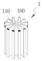
도 1은 본 발명 전기강판 코어가 적층된 상태를 나타낸 도면이다.
도 2는 본 발명 전기강판 코어에 형성되는 오목부 및 돌기부 쪽만 일부 발췌하여 확대하여 나타낸 부분 단면도이다.
도 3은 본 발명 전기강판코어에 돌기부가 오목부에 엠보펀치에 의해 가공되는 상태를 나타낸 도면이다.1 is a view showing a state in which the electrical steel sheet core of the present invention is laminated.
Figure 2 is a partial cross-sectional view showing only an enlarged portion of the recessed portion and the protrusion formed on the electrical steel sheet core of the present invention.
3 is a view showing a state in which the protrusion is processed by the embossed punch in the concave portion in the electrical steel sheet core of the present invention.
이하에서는 첨부한 도면을 참조하여 본 발명에 따른 구성 및 작용을 구체적으로 설명한다. 첨부 도면을 참조하여 설명함에 있어, 도면 부호에 관계없이 동일한 구성요소는 동일한 참조부여를 부여하고, 이에 대한 중복설명은 생략하기로 한다. 제1, 제2 등의 용어는 다양한 구성요소들을 설명하는데 사용될 수 있지만, 상기 구성요소들은 상기 용어들에 의해 한정되어서는 안 된다. 상기 용어들은 하나의 구성요소를 다른 구성요소로부터 구별하는 목적으로만 사용된다.Hereinafter, with reference to the accompanying drawings will be described in detail the configuration and operation according to the present invention. In the description with reference to the accompanying drawings, the same components are given the same reference numerals regardless of the reference numerals, and duplicate description thereof will be omitted. The terms first, second, etc. may be used to describe various components, but the components should not be limited by the terms. The terms are used only for the purpose of distinguishing one component from another.
도 1에 도시된 바와 같이, 본 발명 전기강판코어(1)는 층판(100)에 엠보펀치(200)에 의해 형성되는 오목부(110)와 돌기부(120)가 일직선상에 수직으로 단차를 이루어져 상기 돌기부(120)가 다음 오목부(110)에 결합하게 된다.As shown in FIG. 1, the electrical
상기 층판(100)은 CR-Pree 전기강판 및 현재 사용중 전기강판 및 냉연강판으로 하였다.The
또한, 도 2에 도시된 바와 같이, 상기 오목부(110)의 내측에 2개 이상의 원기둥형상의 홈(111)이 형성된다.In addition, as shown in FIG. 2, two or more
이때, 상기 오목부(110)의 지름이 돌기부(120)의 직경보다 작게 형성하여 억지끼움되도록 하였다.At this time, the diameter of the
또한, 상기 오목부(110)는 삼각형상, 사각형상, 타원형상 중 어느 하나의 것을 선택 사용할 수가 있으며, 상기 오목부(110)에 형성되는 홈(111)의 형상을 연속된 쐐기형상, 톱니형상, 사각형상 중 어느 하나의 것을 선택 사용할 수가 있다.In addition, the
또한, 상기 오목부(110)의 입구 쪽에 경사면을 두어서 돌기부(120)의 삽입을 자연스럽게 되도록 유도하도록 하는 것이 바람직하다.In addition, it is preferable to place the inclined surface on the inlet side of the
상기와 같은 적절한 전기강판코어를 얻기 위해서는 다음과 같은 코어를 선정하여야한다.In order to obtain a suitable electrical steel core as described above, the following core should be selected.
즉, CR-Pree로 이루어진 코어 적층 체결력(코어낱장 (이하 층판 이라고 함)과 코어낱장이 분리될 때까지 붙어있는 힘)이 우수해야된다.In other words, the core lamination fastening force (the core sheet (hereinafter referred to as "laminate plate") consisting of CR-Pree and the force attached until the core sheet is separated) should be excellent.
이때, 코어 적층 체결력이 5kgf 이상이 되어야한다.At this time, the core stacking force should be 5kgf or more.
예를 들면, 우수한 체결력을 얻기 위해 다음과 같이 실험을 하였다.For example, the following experiment was conducted to obtain excellent fastening force.
먼저, 데이터수집을 위해 하기 표1과 같은 조건 하에서 하였다.First, the data were collected under the conditions shown in Table 1 below.
또한, 측정데이터는 측정자가 시료 10개씩 무작위로 추출하여 측정하였으며, 적층력을 푸시 풀(push pull)로 당겼을 시 반복측정이 불가하였다.In addition, the measurement data was measured by a random sample of ten samples, the measurement was not repeated when the lamination force pulled (push pull).
측정항목Metric
시료명
Sample name
계측기명
Instrument Name
측정단위
Unit of measure
규격
standard
체결력Clamping force
036 BL CORE
036 BL CORE
Push pull 게이지
Push pull gauge
0~50kgf
0-50kgf
5kgf이상
More than 5kgf
열수Hydrothermal
시료수sample water
1열
1 row
2열
2 rows
3열
3 row
4열
4 rows
5열
5 rows
평균적으로 1.7~1.9kgf 임을 알 수가 있다.It can be seen that the average is 1.7 ~ 1.9kgf.
상기 측정된 체결력을 그래프로 나타내면 다음과 같다.The measured clamping force is shown as a graph as follows.

평균 : 1~ 1.64kgf로 표준편차 : 0.63kgf가 임을 알 수가 있다.
Mean: 1 ~ 1.64kgf, standard deviation: 0.63kgf.
따라서, 코어의 체결력을 향상시키기 위해서는 아래 그래프와 같은 조건이 필요하다.Therefore, in order to improve the fastening force of the core, the conditions as shown in the graph below are required.

즉, 평균 6.7kgf으로 표준편차 0.5kgf 가 적정 수준임을 알 수가 있다.In other words, the average deviation of 6.7kgf 0.5kgf is the appropriate level.
상기와 같은 조건을 얻기 위해서는 하기와 같은 조건이 필요하다.In order to obtain the above conditions, the following conditions are required.
1) 엠보 펀치 높이 : 오목부를 형성하기 위한 펀치로 엠보 높이 단차에 따른 체결력 변동을 방지하기 위해 대략 0.30~0.45㎜ 유지 할 것1) Emboss Punch Height: Punch to form concave part and keep approximately 0.30 ~ 0.45㎜ to prevent fastening force variation according to emboss height step.
2) 푸셔 펀치 높이 : 오목부에 돌기부가 삽입될 경우 더욱 견고하게 결합하기 위한 펀치로, 펀치 깊이 0.30~0.45㎜ 유지할 것2) Pusher Punch Height: Punch for more firm coupling when the projection is inserted in the recess. Keep the punch depth 0.30 ~ 0.45mm
상기 푸셔 펀치는 오목부에 돌기부 결합시 확실하게 결합시키기 위한 펀치이다.The pusher punch is a punch for reliably engaging the protrusions when engaging the protrusions.
상기와 같은 조건으로 이루어진 층판(100)을 도 3과 같이 엠보다이(120)에 CR-Pree판을 올려놓은 다음 엠보펀치(20)를 이용하여 도 와 같이 여러 형상의 홈을 가지는 오목부(110)와 돌기부(120)를 프레싱 한다. Place the CR-Pree plate on the embossed 120 as shown in Fig. 3 to the
다음 상기와 같이 프레싱된 층판(100)을 적층한 상태에서 푸셔 펀치를 이용하여 완전히 누른다.Next, in the state of laminating the pressed
그러면, 상기 오목부(110)의 내측에 형성된 홈(111)이 함몰되면서 상기 돌기부(120)에 밀착 고정된다.
Then, the
1 : 전기강판코어10 : 엠보다이
100 : 층판110 : 오목부
120 : 돌기부200 : 엠보펀치1: electrical steel core 10: emboil
100: lamellar 110: recess
120: protrusion 200: emboss punch
Claims (5)
Translated fromKorean상기 오목부의 내측에 2개 이상의 원기둥형상의 홈이 형성되어 돌기부와 결합시 함몰되어 상기 돌기부에 밀착고정되도록 한 것을 특징으로 하는 전기강판 코어.
In the electrical steel sheet core in which the protrusions and the recesses are formed in each of the laminated board and the recesses and the protrusions are vertically coupled in a straight line,
Electrical steel sheet core characterized in that two or more cylindrical grooves are formed inside the concave portion to be recessed when engaged with the projection to be fixed in close contact with the projection.
Priority Applications (1)
| Application Number | Priority Date | Filing Date | Title |
|---|---|---|---|
| KR1020100041964AKR101005911B1 (en) | 2010-05-04 | 2010-05-04 | Electrical steel core |
Applications Claiming Priority (1)
| Application Number | Priority Date | Filing Date | Title |
|---|---|---|---|
| KR1020100041964AKR101005911B1 (en) | 2010-05-04 | 2010-05-04 | Electrical steel core |
Publications (1)
| Publication Number | Publication Date |
|---|---|
| KR101005911B1true KR101005911B1 (en) | 2011-01-06 |
Family
ID=43615817
Family Applications (1)
| Application Number | Title | Priority Date | Filing Date |
|---|---|---|---|
| KR1020100041964AExpired - Fee RelatedKR101005911B1 (en) | 2010-05-04 | 2010-05-04 | Electrical steel core |
Country Status (1)
| Country | Link |
|---|---|
| KR (1) | KR101005911B1 (en) |
Citations (3)
| Publication number | Priority date | Publication date | Assignee | Title |
|---|---|---|---|---|
| KR19990023654A (en)* | 1997-08-19 | 1999-03-25 | 제이 엘. 차스킨, 버나드 스나이더, 아더엠. 킹 | Core formed by lamination of rotating laminate, electric motor and core manufacturing method including the core |
| KR20060006131A (en)* | 2004-07-15 | 2006-01-19 | 주식회사 한국성산 | Laminated structure of the core for rotor |
| KR100749832B1 (en) | 2006-07-27 | 2007-08-16 | 준영산업(주) | Armature core and manufacturing method |
- 2010
- 2010-05-04KRKR1020100041964Apatent/KR101005911B1/ennot_activeExpired - Fee Related
Patent Citations (3)
| Publication number | Priority date | Publication date | Assignee | Title |
|---|---|---|---|---|
| KR19990023654A (en)* | 1997-08-19 | 1999-03-25 | 제이 엘. 차스킨, 버나드 스나이더, 아더엠. 킹 | Core formed by lamination of rotating laminate, electric motor and core manufacturing method including the core |
| KR20060006131A (en)* | 2004-07-15 | 2006-01-19 | 주식회사 한국성산 | Laminated structure of the core for rotor |
| KR100749832B1 (en) | 2006-07-27 | 2007-08-16 | 준영산업(주) | Armature core and manufacturing method |
Similar Documents
| Publication | Publication Date | Title |
|---|---|---|
| CN101299379B (en) | Laminar article for electrical use and method and machine for producing the article | |
| US10109417B2 (en) | Laminated iron core and method of manufacturing laminated iron core with caulking protrusion | |
| KR101660074B1 (en) | Rotator core | |
| US6979930B2 (en) | Stator for an automotive alternator | |
| US7260881B2 (en) | Method for manufacturing a stator core for a dynamoelectric machine | |
| US20170040850A1 (en) | Laminated iron core, method for manufacturing laminated iron core, and punch for caulking formation used in the method | |
| JPS59185144A (en) | Method of producing laminated core for electric machine and device | |
| CN102449880A (en) | Stator core and method for manufacturing same | |
| KR920020807A (en) | Apparatus and method for aligning stacked thin plates of a generator | |
| JP6822132B2 (en) | Electronic components and their manufacturing methods | |
| CN104868664A (en) | Method of punching core piece and stacked core | |
| US6847285B2 (en) | Interlock tabs for laminations | |
| US2948051A (en) | Method of manufacturing an electrically conductive winding pattern | |
| JPWO2011077830A1 (en) | Laminated core, electric motor provided with the laminated core, and laminated core manufacturing method | |
| KR101005911B1 (en) | Electrical steel core | |
| DE102011114280A1 (en) | Stator of electric machine used in e.g. electric car, has stator segments that are held by stator support, and electrical insulation film that is arranged between stator support and stator segment in axial direction | |
| CN105575588A (en) | Surface-mount inductor and method for manufacturing the same | |
| CN113226586A (en) | Method for producing a stack of stacked metal parts comprising a multi-layer blanking process step | |
| CN107317405B (en) | Lamination stack for producing the stator and/or rotor of an electric motor and generator | |
| JP2000150289A (en) | Multilayer ceramic capacitors | |
| JP2001096318A (en) | Laminate manufacturing method and apparatus | |
| JP6248965B2 (en) | Manufacturing method of core of rotating electrical machine | |
| JP2011151923A (en) | Laminated core and manufacturing method for the same | |
| JP5442585B2 (en) | Electric motor stator and method of manufacturing the same | |
| JP5297147B2 (en) | Manufacturing method of magnet mounted rotor core |
Legal Events
| Date | Code | Title | Description |
|---|---|---|---|
| A201 | Request for examination | ||
| PA0109 | Patent application | St.27 status event code:A-0-1-A10-A12-nap-PA0109 | |
| PA0201 | Request for examination | St.27 status event code:A-1-2-D10-D11-exm-PA0201 | |
| A302 | Request for accelerated examination | ||
| PA0302 | Request for accelerated examination | St.27 status event code:A-1-2-D10-D17-exm-PA0302 St.27 status event code:A-1-2-D10-D16-exm-PA0302 | |
| E902 | Notification of reason for refusal | ||
| PE0902 | Notice of grounds for rejection | St.27 status event code:A-1-2-D10-D21-exm-PE0902 | |
| E13-X000 | Pre-grant limitation requested | St.27 status event code:A-2-3-E10-E13-lim-X000 | |
| P11-X000 | Amendment of application requested | St.27 status event code:A-2-2-P10-P11-nap-X000 | |
| P13-X000 | Application amended | St.27 status event code:A-2-2-P10-P13-nap-X000 | |
| E701 | Decision to grant or registration of patent right | ||
| PE0701 | Decision of registration | St.27 status event code:A-1-2-D10-D22-exm-PE0701 | |
| GRNT | Written decision to grant | ||
| PR0701 | Registration of establishment | St.27 status event code:A-2-4-F10-F11-exm-PR0701 | |
| PR1002 | Payment of registration fee | St.27 status event code:A-2-2-U10-U11-oth-PR1002 Fee payment year number:1 | |
| PG1601 | Publication of registration | St.27 status event code:A-4-4-Q10-Q13-nap-PG1601 | |
| FPAY | Annual fee payment | Payment date:20131220 Year of fee payment:4 | |
| PR1001 | Payment of annual fee | St.27 status event code:A-4-4-U10-U11-oth-PR1001 Fee payment year number:4 | |
| FPAY | Annual fee payment | Payment date:20141226 Year of fee payment:5 | |
| PR1001 | Payment of annual fee | St.27 status event code:A-4-4-U10-U11-oth-PR1001 Fee payment year number:5 | |
| FPAY | Annual fee payment | Payment date:20151207 Year of fee payment:6 | |
| PR1001 | Payment of annual fee | St.27 status event code:A-4-4-U10-U11-oth-PR1001 Fee payment year number:6 | |
| P22-X000 | Classification modified | St.27 status event code:A-4-4-P10-P22-nap-X000 | |
| FPAY | Annual fee payment | Payment date:20161207 Year of fee payment:7 | |
| PR1001 | Payment of annual fee | St.27 status event code:A-4-4-U10-U11-oth-PR1001 Fee payment year number:7 | |
| FPAY | Annual fee payment | Payment date:20171207 Year of fee payment:8 | |
| PR1001 | Payment of annual fee | St.27 status event code:A-4-4-U10-U11-oth-PR1001 Fee payment year number:8 | |
| PR1001 | Payment of annual fee | St.27 status event code:A-4-4-U10-U11-oth-PR1001 Fee payment year number:9 | |
| FPAY | Annual fee payment | Payment date:20191230 Year of fee payment:10 | |
| PR1001 | Payment of annual fee | St.27 status event code:A-4-4-U10-U11-oth-PR1001 Fee payment year number:10 | |
| PC1903 | Unpaid annual fee | St.27 status event code:A-4-4-U10-U13-oth-PC1903 Not in force date:20201229 Payment event data comment text:Termination Category : DEFAULT_OF_REGISTRATION_FEE | |
| PN2301 | Change of applicant | St.27 status event code:A-5-5-R10-R13-asn-PN2301 St.27 status event code:A-5-5-R10-R11-asn-PN2301 | |
| PC1903 | Unpaid annual fee | St.27 status event code:N-4-6-H10-H13-oth-PC1903 Ip right cessation event data comment text:Termination Category : DEFAULT_OF_REGISTRATION_FEE Not in force date:20201229 | |
| PN2301 | Change of applicant | St.27 status event code:A-5-5-R10-R13-asn-PN2301 St.27 status event code:A-5-5-R10-R11-asn-PN2301 |