KR101004628B1 - dispenser - Google Patents
dispenserDownload PDFInfo
- Publication number
- KR101004628B1 KR101004628B1KR1020100011089AKR20100011089AKR101004628B1KR 101004628 B1KR101004628 B1KR 101004628B1KR 1020100011089 AKR1020100011089 AKR 1020100011089AKR 20100011089 AKR20100011089 AKR 20100011089AKR 101004628 B1KR101004628 B1KR 101004628B1
- Authority
- KR
- South Korea
- Prior art keywords
- inner container
- contents
- container
- present
- dispenser
- Prior art date
- Legal status (The legal status is an assumption and is not a legal conclusion. Google has not performed a legal analysis and makes no representation as to the accuracy of the status listed.)
- Expired - Fee Related
Links
Images


Classifications
- B—PERFORMING OPERATIONS; TRANSPORTING
- B65—CONVEYING; PACKING; STORING; HANDLING THIN OR FILAMENTARY MATERIAL
- B65D—CONTAINERS FOR STORAGE OR TRANSPORT OF ARTICLES OR MATERIALS, e.g. BAGS, BARRELS, BOTTLES, BOXES, CANS, CARTONS, CRATES, DRUMS, JARS, TANKS, HOPPERS, FORWARDING CONTAINERS; ACCESSORIES, CLOSURES, OR FITTINGS THEREFOR; PACKAGING ELEMENTS; PACKAGES
- B65D83/00—Containers or packages with special means for dispensing contents
- B65D83/14—Containers for dispensing liquid or semi-liquid contents by internal gaseous pressure, i.e. aerosol containers comprising propellant
- B65D83/60—Containers for dispensing liquid or semi-liquid contents by internal gaseous pressure, i.e. aerosol containers comprising propellant with contents and propellant separated
- B65D83/62—Containers for dispensing liquid or semi-liquid contents by internal gaseous pressure, i.e. aerosol containers comprising propellant with contents and propellant separated by membranes, bags or the like
- B—PERFORMING OPERATIONS; TRANSPORTING
- B65—CONVEYING; PACKING; STORING; HANDLING THIN OR FILAMENTARY MATERIAL
- B65D—CONTAINERS FOR STORAGE OR TRANSPORT OF ARTICLES OR MATERIALS, e.g. BAGS, BARRELS, BOTTLES, BOXES, CANS, CARTONS, CRATES, DRUMS, JARS, TANKS, HOPPERS, FORWARDING CONTAINERS; ACCESSORIES, CLOSURES, OR FITTINGS THEREFOR; PACKAGING ELEMENTS; PACKAGES
- B65D83/00—Containers or packages with special means for dispensing contents
- B65D83/14—Containers for dispensing liquid or semi-liquid contents by internal gaseous pressure, i.e. aerosol containers comprising propellant
- B65D83/60—Containers for dispensing liquid or semi-liquid contents by internal gaseous pressure, i.e. aerosol containers comprising propellant with contents and propellant separated
- B65D83/64—Containers for dispensing liquid or semi-liquid contents by internal gaseous pressure, i.e. aerosol containers comprising propellant with contents and propellant separated by pistons
Landscapes
- Chemical & Material Sciences (AREA)
- Dispersion Chemistry (AREA)
- Engineering & Computer Science (AREA)
- Mechanical Engineering (AREA)
- Containers And Packaging Bodies Having A Special Means To Remove Contents (AREA)
Abstract
Translated fromKoreanDescription
Translated fromKorean본 발명은 디스펜서에 관한 것으로, 특히 내부용기에 내용물의 재충전이 가능하고, 내부용기 내의 내용물 배출이 최대한 가능하도록 한 디스펜서에 관한 것이다.The present invention relates to a dispenser, and more particularly, to a dispenser capable of refilling the contents in an inner container and maximally discharging the contents in the inner container.
특히 본 발명은 내부용기와 외부용기 사이에 압축공기를 충진함에 따라, 이 압축공기에 의하여 내용물의 토출력(배출력)을 향상시키는 것을 특징으로 하는 바, 일반적인 프레온 가스를 사용하지 않고 인체에 무해한 친환경적인 공기를 이용한 디스펜서에 관한 것이다.In particular, the present invention is characterized in that by filling the compressed air between the inner container and the outer container, by improving the soil output (discharge output) of the contents by the compressed air, harmless to the human body without using a general freon gas It relates to a dispenser using environmentally friendly air.
액상 또는 점액상의 화장품은 내용물을 일정량씩 용이하게 토출시켜 사용할 수 있도록 디스펜서에 저장되어 제공된다.Liquid or mucus cosmetics are stored and provided in a dispenser so that the contents can be easily discharged by a predetermined amount.
이러한 디스펜서는 내용물이 저장되는 용기의 상단에 펌핑부가 장착되어 이루어진다.Such a dispenser is provided with a pumping part mounted on the top of a container in which contents are stored.
디스펜서에 대해 보다 상세히 설명하면, 일측에 노즐이 형성되어 이 노즐을 통해 내용물이 유출되도록 된 버튼이 구비되어, 이 버튼을 눌러 디스펜서를 펌핑시키면 내용물이 토출되도록 구성된다.In more detail with respect to the dispenser, a nozzle is formed on one side and a button is provided to allow the contents to flow out through the nozzle. When the button is pressed to pump the dispenser, the contents are discharged.
이러한 종래의 디스펜서는 헤어무스나 쉐이브폼 등 액체와 에어를 혼합시켜 사용하는 제품들에 적용되는 것으로, 프레온 가스와 같은 압축가스를 이용하게 된다.Such a conventional dispenser is applied to products using a mixture of liquid and air such as hair mousse or shave foam, and uses a compressed gas such as a freon gas.
이에 따라, 폭발이나 화재의 위험과 인체에 유해하고 오존층 파괴 등의 환경공해를 유발할 뿐만 아니라 내용물의 재충전이 불가능하다는 문제점이 있다.Accordingly, there is a problem that the risk of explosion or fire and harmful to the human body and cause environmental pollution such as destruction of the ozone layer, as well as impossible to recharge the contents.
본 발명은 상기와 같은 문제점을 해결하기 위해 창안한 것으로, 그 목적은 폭발이나 화재 위험이 있는 가스 주입이 필요 없고 내용물의 재충전이 가능한 디스펜서를 제공하는 데 있다.The present invention has been made to solve the above problems, and an object thereof is to provide a dispenser capable of recharging the contents without the need for gas injection with the risk of explosion or fire.
또한, 본 발명은 내부용기 내의 내용물의 배출이 최대한 가능하도록 한 디스펜서를 제공하는 데 있다.In addition, the present invention is to provide a dispenser capable of maximizing the discharge of the contents in the inner container.
특히 본 발명은 내부용기와 외부용기 사이에 압축공기를 충진하여, 이 압축공기에 의하여 내용물의 토출력(배출력)을 향상시키고, 종래와 같은 프레온 가스를 사용하지 않고 인체에 무해한 친환경적인 공기를 이용하는 디스펜서를 제공하는 데 있다.In particular, the present invention is to fill the compressed air between the inner container and the outer container, to improve the earth output (discharge output) of the contents by the compressed air, and to use environmentally friendly air that is harmless to the human body without using the conventional freon gas It is to provide a dispenser to be used.
상기와 같은 목적을 이루기 위해 본 발명은 외부용기(300)와, 상기 외부용기(300)의 내부에 삽입되고 내용물이 저장되는 내부용기(200)와, 상기 외부용기(300) 및 내부용기(200)의 상단부에 결합되어 내부용기(200) 내의 내용물을 토출시키는 펌핑부(100)를 포함하고, 상기 내부용기(200)는 수축 및 팽창이 가능한 재질로 이루어지고, 블로우 사출을 통한 다수의 주름(210)이 형성되며, 상부에는 펌핑부(100)와 결합하기 위한 결합구(220)가 구성되고, 상기 외부용기(300)와 내부용기 사이에 압축공기를 충진하여 상기 압축공기에 의한 내용물 토출(배출)이 이루어지도록 구성하는 것을 특징으로 하는 디스펜서이다.In order to achieve the above object, the present invention provides an
또한, 본 발명은 상기 내부용기(200)의 외주면에 압축용 고무밴드(410)를 더 구성하는 것을 특징으로 하는 디스펜서이다.In addition, the present invention is a dispenser, characterized in that further comprises a
또한, 본 발명은 상기 내부용기(200)의 외주면에 탄성의 스틸밴드(420)를 더 구성하고, 상기 스틸밴드(420)의 일부를 절개하여 세워 형성된 다수의 탄성스틸편(421)을 구성하여; 상기 내부용기(200) 내의 내용물이 점차 토출됨에 따라 상기 탄성스틸편(421)은 끝 부분이 외부용기(300)의 내면에 맞닿은 상태를 유지하면서 점차 세워지도록 하는 것을 특징으로 하는 디스펜서이다.In addition, the present invention further comprises an
이상에서와 같이, 본 발명의 디스펜서는 폭발이나 화재 위험이 있는 가스 주입이 필요 없고 내용물의 재충전이 가능하다는 장점이 있다.As described above, the dispenser of the present invention has the advantage that it is possible to refill the contents without the need for gas injection, which may cause an explosion or fire.
또한, 본 발명의 디스펜서는 내부용기 내의 내용물의 배출이 최대한 가능하다는 장점이 있다.In addition, the dispenser of the present invention has the advantage that it is possible to maximize the discharge of the contents in the inner container.
또한, 본 발명은 내부용기와 외부용기 사이에 압축공기를 충진하여, 이 압축공기에 의하여 내용물의 토출력(배출력)을 향상시킨다.In addition, the present invention fills the compressed air between the inner container and the outer container, thereby improving the soil output (discharge output) of the contents by the compressed air.
또한, 본 발명은 외부용기와 내부용기 사이에 충진된 압축공기만으로도 내용물 토출(배출)이 가능하도록 만든 친환경제품이다.In addition, the present invention is an environmentally friendly product made to enable the discharge (discharge) of the contents with only the compressed air filled between the outer container and the inner container.
특히 현재 시중에 많이 나와 있는 프레온가스와 액화가스를 혼합한 제품이 인체에 해로운 영향을 미치고 온실가스의 주범으로 인식되고 있는데, 본 발명은 이러한 문제를 대체할 친환경제품이자 정부의 녹색성장에 가장 이상적인 제품이다.In particular, the products of the mixture of Freon gas and liquefied gas on the market are known to have harmful effects on the human body and to be the main culprit of the greenhouse gas. Product.
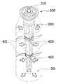
도 1은 본 발명의 일실시예에 따른 디스펜서의 분해사시도
도 2는 본 발명의 일실시예에 따른 디스펜서의 결합사시도
도 3은 본 발명의 일실시예에 따른 디스펜서의 정면도
도 4는 도 2의 디스펜서의 내부용기가 팽창된 상태의 사시도
도 5는 본 발명의 다른 일실시예에 따른 디스펜서의 사시도
도 6은 도 5의 디스펜서의 내부용기가 팽창된 상태의 사시도
도 7은 본 발명의 또 다른 일실시예에 따른 디스펜서의 사시도
도 8은 도 7의 디스펜서의 내부용기가 팽창된 상태의 사시도1 is an exploded perspective view of a dispenser according to an embodiment of the present invention.
Figure 2 is a perspective view of the combination of the dispenser according to an embodiment of the present invention
3 is a front view of the dispenser according to an embodiment of the present invention.
Figure 4 is a perspective view of the inner container is inflated state of the dispenser of Figure 2
5 is a perspective view of a dispenser according to another embodiment of the present invention.
FIG. 6 is a perspective view of an inner container of the dispenser of FIG. 5 inflated
7 is a perspective view of a dispenser according to another embodiment of the present invention
FIG. 8 is a perspective view of an inner container of the dispenser of FIG. 7 inflated
이하, 첨부된 도면을 참조하여 본 발명에 따른 바람직한 실시예를 상세하게 설명하고자 한다.Hereinafter, exemplary embodiments of the present invention will be described in detail with reference to the accompanying drawings.
도 1 내지 도 3은 본 발명의 일실시예에 따른 디스펜서의 분해사시도, 결합사시도 및 정면도로, 내부용기가 수축된 상태를 나타내는 것이고, 도 4는 도 2의 디스펜서의 내부용기가 팽창된 상태를 나타내는 사시도이다.1 to 3 is an exploded perspective view, a combined perspective view and a front view of the dispenser according to an embodiment of the present invention, showing a state in which the inner container is shrunk, Figure 4 is an expanded state of the inner container of the dispenser of FIG. It is a perspective view showing.
도면을 참조하면, 본 발명의 디스펜서는 크게 펌핑부(100), 내부용기(200) 및 외부용기(300)를 포함하여 구성된다.Referring to the drawings, the dispenser of the present invention is largely configured to include a
외부용기(300)는 상부가 개방된 용기로, 상부는 펌핑부(100)와 체결하기 위한 체결구(310)가 형성된다.The
또한, 외부용기(300)는 변형이 불가능한 재질로 구성되는 것으로, 일례로서 고형의 플라스틱이나 금속 재질로 이루어진다.In addition, the
이 외부용기(300) 내에는 압축공기(301)가 충진된다. 이 압축공기(301)의 힘(화살표로 표시)은 내부용기(200) 내의 내용물을 토출(배출)시킬 때, 내부용기(200)에 작용하게 된다.The
내부용기(200)는 외부용기(300) 내부에 삽입되고, 액상이나 젤 형상의 내용물이 저장되는 용기로, 상부에는 펌핑부(100)와 결합하기 위한 결합구(220)가 형성된다.The
또한, 내부용기(200)는 수축 및 팽창이 가능한 재질로 이루어지고, 블로우(Blow) 사출을 통한 다수의 주름(210)이 형성된다.In addition, the
일례로, 내부용기(200)는 질기고 무공해성 필름(예: PPT, PET 등)으로 이루어진다.For example, the
주름(210)은 상하방향으로 형성되는데, 내부용기(200) 내에 내용물이 충진됨에 따라 도 3처럼 팽창하여 점차 펴지게 된다. 이때, 팽창은 내부용기(200)의 외면이 외부용기(300) 내면에 닿을 때까지 이루어질 수 있다.The
펌핑부(100)는 외부용기(300) 및 내부용기(200)의 상단부인 체결구(310) 및 결합구(220)에 결합되는 것으로, 내부용기(200) 내의 내용물을 토출시키는 역할을 한다.The
보다 구체적으로 설명하면, 펌핑부(100)는 일측에 노즐(미도시)이 형성되어 이 노즐을 통해 내용물이 유출되도록 된 버튼(미도시)이 구비되어, 이 버튼을 눌러 디스펜서를 펌핑시키면 내용물이 토출되도록 구성된다. 즉, 버튼을 누르면 도 1의 누름부(110)가 가압되고, 이 누름부(110)와 연결된 스프링(미도시)이 압착되어 진공압을 발생시키게 되고, 이에 따라 토출공이 개방되어 내용물은 토출공을 통해 외부로 토출된다.More specifically, the
펌핑부(100)의 내부에는 체크밸브(check valve)가 구성되어 내용물이 역류되는 것을 방지한다.A check valve is configured inside the
상기와 같이, 내부용기(200) 내의 내용물이 점차 토출됨에 따라 내부용기(200)는 점차 쭈구러지게(수축) 된다.As described above, as the contents of the
펌핑부(100)는 종래 공지된 디스펜서의 펌핑부(100)로 대체할 수 있다. 즉, 등록실용신안 제2000-14083호(명칭: 디스펜서), 등록실용신안 제2000-36103호(명칭: 디스펜서 용기) 등에 나와 있는 펌핑부를 참조하면 된다.The
본 발명은 외부용기(300) 내에 압축공기(301)를 충진한다. 즉, 외부용기(300)와 내부용기(200) 사이에 압축공기(301)를 충진함에 따라 이 압축공기(301)에 의하여 내용물의 토출력을 더욱 향상시킬 수 있다.The present invention fills the
특히 본 발명은 종래와 같은 프레온 가스를 사용하지 않고 인체에 무해한 친환경적인 공기를 이용한다는 점에서 매우 유용하다.
In particular, the present invention is very useful in that it uses environmentally friendly air, which is harmless to the human body, without using a conventional freon gas.
도 5는 본 발명의 다른 일실시예에 따른 디스펜서의 사시도이고, 도 6은 도 5의 디스펜서의 내부용기(200)가 팽창된 상태의 사시도이다.5 is a perspective view of a dispenser according to another embodiment of the present invention, Figure 6 is a perspective view of the
도 5 및 도 6에 나타난 디스펜서는 도 1 내지 도 4의 디스펜서에 비해 내부용기(200)의 외주면에 압축용 고무밴드(410)가 더 구성된다는 것이다.The dispenser shown in FIGS. 5 and 6 is that the
압축용 고무밴드(410)는 탄성 성질을 가지고 있어, 내용물이 토출됨에 따라 수축하게 된다.The
상기와 같이, 내부용기(200)의 외면에 압축용 고무밴드(410)를 구성함에 따라 고무밴드(410)의 조임력에 의하여 내용물의 토출력을 향상시킬 수 있을 뿐만 아니라 내부용기(200)에서 내용물의 토출을 최대한 이끌어낼 수 있다.
As described above, by configuring the
도 7은 본 발명의 또 다른 일실시예에 따른 디스펜서의 사시도이고, 도 8은 도 7의 디스펜서의 내부용기가 팽창된 상태의 사시도이다.Figure 7 is a perspective view of a dispenser according to another embodiment of the present invention, Figure 8 is a perspective view of the inner container of the dispenser of Figure 7 in an expanded state.
도 7 및 도 8에 나타난 디스펜서는 도 1 내지 도 4의 디스펜서에 비해 내부용기(200)의 외주면에 탄성의 스틸밴드(420)가 더 구성된다는 것이다.7 and 8 is that the
스틸밴드(420)는 띠 형상으로 이루어지고, 이 스틸밴드(420)에는 일부분을 절개하여 세워 형성된 다수의 탄성스틸편(421)이 구성된다. 이에 따라, 스틸밴드(420)의 절개 부위에는 절개공(422)이 형성된다.The
상기 내부용기(200) 내에 내용물이 최대한으로 충진되면 도 8처럼 탄성스틸편(421)이 절개공(422)의 위치까지 이르게 되고, 점차 내용물이 토출됨에 따라 상기 탄성스틸편(421)은 점점 세워져 도 7처럼 된다.When the contents are filled to the maximum in the
이때, 탄성스틸편(421)의 끝부분은 외부용기(300)의 내면에 맞닿은 상태를 유지하게 된다.At this time, the end portion of the
이에 따라, 내부용기(200)가 점차 수축됨에 따라 탄성스틸편(421)이 점차 세워지게 되고, 반대로 내부용기(200)가 점차 팽창됨에 따라 탄성스틸편(421)이 점차 눕혀지게 된다.Accordingly, as the
상기와 같이, 내부용기(200)의 외주면에 탄성스틸편(421)을 구성함에 따라 내용물의 토출력을 향상시킬 수 있을 뿐만 아니라 내부용기(200)에서 내용물의 토출을 최대한 이끌어낼 수 있다.As described above, by configuring the
상기와 같이, 본 발명의 바람직한 실시예를 참조하여 설명하였지만, 해당 기술 분야의 숙련된 당업자라면 하기의 특허청구범위에 기재된 본 발명의 사상 및 영역으로부터 벗어나지 않는 범위 내에서 본 발명을 다양하게 수정 및 변경시킬 수 있음을 이해할 수 있을 것이다.As described above, with reference to the preferred embodiment of the present invention, those skilled in the art will be variously modified and modified within the scope of the present invention without departing from the spirit and scope of the present invention described in the claims below. It will be appreciated that it can be changed.
100: 펌핑부
110: 누름부
200: 내부용기
210: 주름
220: 결합구
300: 외부용기
301: 압축공기
310: 체결구
410: 고무밴드
420: 스틸밴드
421: 탄성스틸편
422: 절개공100: pumping part
110: pressing part
200: inner container
210: wrinkle
220: splice
300: outer container
301: compressed air
310: fastener
410: rubber band
420: steel band
421: elastic steel piece
422: incision
Claims (3)
Translated fromKorean상기 내부용기(200)는 수축 및 팽창이 가능한 재질로 이루어지고, 블로우 사출을 통한 다수의 주름(210)이 형성되며, 상부에는 펌핑부(100)와 결합하기 위한 결합구(220)와, 상기 내부용기(200)의 외주면에 탄성의 스틸밴드(420)와, 상기 스틸밴드(420)의 일부를 절개하여 세워 형성된 다수의 탄성스틸편(421)을 구성하여;
상기 내부용기(200) 내의 내용물이 점차 토출됨에 따라 상기 탄성스틸편(421)은 끝 부분이 외부용기(300)의 내면에 맞닿은 상태를 유지하면서 점차 세워지도록 하고,
상기 외부용기(300)와 내부용기 사이에 압축공기(301)를 충진하여, 상기 압축공기(301)에 의한 내용물 토출(배출)이 이루어지도록 구성하는 것을 특징으로 하는 디스펜서.The outer container 300, the inner container 200 is inserted into the outer container 300 and the contents are stored, and coupled to the upper end of the outer container 300 and the inner container 200, the inner container 200 A pumping part (100) for discharging the contents in the column);
The inner container 200 is made of a material that can be contracted and expanded, a plurality of pleats 210 through blow injection is formed, the upper coupling portion 220 for coupling with the pumping unit 100, and An elastic steel band 420 on the outer circumferential surface of the inner container 200 and a plurality of elastic steel pieces 421 formed by cutting a portion of the steel band 420 upright;
As the contents in the inner container 200 are gradually discharged, the elastic steel piece 421 is gradually erected while maintaining the end portion in contact with the inner surface of the outer container 300.
The compressed air 301 is filled between the outer container 300 and the inner container, the dispenser, characterized in that configured to discharge the contents (discharge) by the compressed air (301).
상기 내부용기(200)의 외주면에 압축용 고무밴드(410)를 더 구성하는 것을 특징으로 하는 디스펜서.The method of claim 1,
Dispenser, characterized in that further configured to the compression rubber band 410 on the outer peripheral surface of the inner container (200).
Priority Applications (6)
| Application Number | Priority Date | Filing Date | Title |
|---|---|---|---|
| KR1020100011089AKR101004628B1 (en) | 2010-02-05 | 2010-02-05 | dispenser |
| JP2011018984AJP2011162265A (en) | 2010-02-05 | 2011-01-31 | Dispenser |
| CN2011100725657ACN102190127A (en) | 2010-02-05 | 2011-02-01 | Dispenser |
| US13/018,678US20110192865A1 (en) | 2010-02-05 | 2011-02-01 | Dispenser |
| EP11153428.5AEP2354038A3 (en) | 2010-02-05 | 2011-02-04 | Dispenser |
| IN277DE2011IN2011DE00277A (en) | 2010-02-05 | 2011-02-04 | Dispenser |
Applications Claiming Priority (1)
| Application Number | Priority Date | Filing Date | Title |
|---|---|---|---|
| KR1020100011089AKR101004628B1 (en) | 2010-02-05 | 2010-02-05 | dispenser |
Publications (1)
| Publication Number | Publication Date |
|---|---|
| KR101004628B1true KR101004628B1 (en) | 2011-01-03 |
Family
ID=43615620
Family Applications (1)
| Application Number | Title | Priority Date | Filing Date |
|---|---|---|---|
| KR1020100011089AExpired - Fee RelatedKR101004628B1 (en) | 2010-02-05 | 2010-02-05 | dispenser |
Country Status (6)
| Country | Link |
|---|---|
| US (1) | US20110192865A1 (en) |
| EP (1) | EP2354038A3 (en) |
| JP (1) | JP2011162265A (en) |
| KR (1) | KR101004628B1 (en) |
| CN (1) | CN102190127A (en) |
| IN (1) | IN2011DE00277A (en) |
Cited By (5)
| Publication number | Priority date | Publication date | Assignee | Title |
|---|---|---|---|---|
| KR101237393B1 (en)* | 2011-01-27 | 2013-02-26 | 김홍배 | Storing vessel having dual structure |
| KR20140117338A (en)* | 2014-09-16 | 2014-10-07 | 한용규 | Folder tube of compression spray vessel socket |
| KR101457647B1 (en)* | 2012-12-31 | 2014-11-13 | 주식회사 제이씨코퍼레이션 | Dispenser |
| KR101559845B1 (en) | 2013-10-23 | 2015-10-15 | 탁윤우 | A Dispenser |
| WO2016043494A3 (en)* | 2014-09-16 | 2016-05-06 | 한용규 | Corrugated tube socket of compression injection container and injection button |
Families Citing this family (10)
| Publication number | Priority date | Publication date | Assignee | Title |
|---|---|---|---|---|
| US11814239B2 (en) | 2011-05-16 | 2023-11-14 | The Procter & Gamble Company | Heating of products in an aerosol dispenser and aerosol dispenser containing such heated products |
| US9296550B2 (en)* | 2013-10-23 | 2016-03-29 | The Procter & Gamble Company | Recyclable plastic aerosol dispenser |
| DE102012021775B4 (en)* | 2012-11-06 | 2014-08-21 | Leibinger Gmbh | Device for filling or emptying a container |
| US8800815B1 (en)* | 2013-02-25 | 2014-08-12 | Pibed Limited | Container for use with a counter mounted dispensing system |
| CN103193024A (en)* | 2013-04-07 | 2013-07-10 | 惠州宝柏包装有限公司 | Press pump capable of standing |
| JP6762133B2 (en)* | 2016-04-28 | 2020-09-30 | 株式会社ダイゾー | Discharge container, discharge product using it, and manufacturing method of discharge container |
| US10526133B2 (en) | 2017-02-28 | 2020-01-07 | The Procter & Gamble Company | Aerosol dispenser having a safety valve |
| WO2019025832A1 (en)* | 2017-08-02 | 2019-02-07 | 石榴创新有限公司 | Pneumatic extrusion container and product filling and extruding method |
| WO2019210184A1 (en)* | 2018-04-27 | 2019-10-31 | Rpg Imx Llc | Systems and methods for dispensing components for customized compositions and formulations |
| IL265513B2 (en)* | 2019-03-20 | 2023-03-01 | Vaserman Elchanan | Apparatus for filling inflatable containers for feeding babies |
Citations (4)
| Publication number | Priority date | Publication date | Assignee | Title |
|---|---|---|---|---|
| JPH10181762A (en) | 1996-12-25 | 1998-07-07 | Koichi Yoshikawa | Tool for extruding content in container |
| JPH11292165A (en)* | 1998-04-06 | 1999-10-26 | Osaka Ship Building Co Ltd | Gel dispenser |
| JP2001146260A (en) | 1999-11-19 | 2001-05-29 | Taisei Kako Co Ltd | Discharge container |
| JP2009220845A (en) | 2008-03-14 | 2009-10-01 | Sunstar Engineering Inc | Dispensing device exclusively used for flexible container |
Family Cites Families (40)
| Publication number | Priority date | Publication date | Assignee | Title |
|---|---|---|---|---|
| US2389791A (en)* | 1944-04-06 | 1945-11-27 | Ideal Roller & Mfg Company | Accumulator |
| US2471852A (en)* | 1947-07-19 | 1949-05-31 | Bau Robert Gordon | Dispenser with flow restricting valve |
| US2627365A (en)* | 1948-02-25 | 1953-02-03 | Gabler Josef | Cream box |
| FR1314002A (en)* | 1961-11-24 | 1963-01-04 | Method and device for dispensing a non-compacted substance | |
| US3339803A (en)* | 1965-03-05 | 1967-09-05 | Arde Inc | Fluid storage and expulsion system |
| US3945539A (en)* | 1966-08-16 | 1976-03-23 | Thiokol Corporation | Method and apparatus for expelling fluids |
| US3508686A (en)* | 1966-08-16 | 1970-04-28 | Thiokol Chemical Corp | Apparatus for positively displacing fluids |
| US3592360A (en)* | 1967-06-28 | 1971-07-13 | Arde Inc | Cylindrical fluid storage and expulsion tank |
| US3731854A (en)* | 1971-07-12 | 1973-05-08 | D Casey | Collapsible container liner |
| BE779300A (en)* | 1972-02-11 | 1972-05-30 | Ipc Internationale Presspack C | DEVICE SUITABLE FOR CONTAINING AND DISTRIBUTING LIQUID OR PASTE MATERIALS, |
| DE2644780A1 (en)* | 1976-10-04 | 1978-04-06 | Hago Chemie Gmbh & Co | Mixed material dispensing appts. - has simultaneously operated valves connected between individual vessels and static mixer |
| CA1077001A (en)* | 1976-10-21 | 1980-05-06 | Winfried J. Werding | Appliance for discharging gaseous liquid or pasty product, and process of its manufacture |
| US4077543A (en)* | 1977-02-18 | 1978-03-07 | Continental Can Company, Inc. | Propellantless aerosol container |
| US4423829A (en)* | 1980-08-28 | 1984-01-03 | Container Industries Inc. | Apparatus for containing and dispensing fluids under pressure and method of manufacturing same |
| US4330066A (en)* | 1980-11-21 | 1982-05-18 | Robert Berliner | Receptacle with collapsible internal container |
| US4387833A (en)* | 1980-12-16 | 1983-06-14 | Container Industries, Inc. | Apparatus for containing and dispensing fluids under pressure and method of producing same |
| EP0105537A3 (en)* | 1982-10-04 | 1985-07-03 | Aerosol-Service Ag | Two-compartment container |
| US4964540A (en)* | 1984-10-17 | 1990-10-23 | Exxel Container, Inc. | Pressurized fluid dispenser and method of making the same |
| US5111971A (en)* | 1989-05-26 | 1992-05-12 | Robert Winer | Self-pressurized container having a convoluted liner and an elastomeric sleeve |
| US5232126A (en)* | 1989-05-26 | 1993-08-03 | Robert Winer | Liner for dispensing container |
| DE3923903A1 (en)* | 1989-07-19 | 1991-01-24 | Hirsch Anton | METHOD FOR FILLING COMPRESSED GAS PACKS AND COMPRESSED GAS PACKING |
| DE9007315U1 (en)* | 1990-06-09 | 1991-10-10 | Hirsch, Anton, 7928 Giengen | Valve unit for insertion into a pressurized gas packaging |
| US5115944A (en)* | 1990-08-14 | 1992-05-26 | Illinois Tool Works Inc. | Fluid dispenser having a collapsible inner bag |
| US5301838A (en)* | 1991-01-23 | 1994-04-12 | Continental Pet Technologies, Inc. | Multilayer bottle with separable inner layer and method for forming same |
| JP3108147B2 (en)* | 1991-09-18 | 2000-11-13 | 釜屋化学工業株式会社 | Container and manufacturing method thereof |
| JP3054988B2 (en)* | 1993-06-28 | 2000-06-19 | 宣行 杉村 | accumulator |
| US5887752A (en)* | 1996-08-27 | 1999-03-30 | Chrysler Corporation | Method and apparatus for extracting excess material from containers |
| JP3491865B2 (en)* | 1996-09-09 | 2004-01-26 | 理想科学工業株式会社 | Resource-saving and environmental protection type container and its reinforcing case |
| JP3992256B2 (en)* | 1998-10-01 | 2007-10-17 | 東洋エアゾール工業株式会社 | Double aerosol container and manufacturing method thereof |
| US6102251A (en)* | 1999-06-23 | 2000-08-15 | Daimlerchrysler Corporation | Method and apparatus for extracting excess material from containers |
| WO2002062678A1 (en)* | 2001-02-08 | 2002-08-15 | Stoffel, Hans, F. | Method for producing spray cans comprising an inner container, and corresponding spray can |
| ATE490932T1 (en)* | 2002-06-26 | 2010-12-15 | Daizo Co Ltd | PACKAGING CONTAINER FOR DISCHARGING MULTIPLE CONTENTS, PACKAGING PRODUCT WITH THE PACKAGING CONTAINER AND METHOD FOR PRODUCING THE PACKAGING PRODUCT |
| US20040067394A1 (en)* | 2002-09-30 | 2004-04-08 | Kabushiki Kaisha Toshiba | Liquid cartridge |
| US7308991B2 (en)* | 2003-11-17 | 2007-12-18 | Advanced Technology Materials, Inc. | Blown bottle with intrinsic liner |
| CA2572162A1 (en)* | 2005-12-23 | 2007-06-23 | Mpi Packaging Inc. | Barrier package aerosol dispenser |
| JP5103871B2 (en)* | 2006-01-27 | 2012-12-19 | マックス株式会社 | Gas cartridge |
| JP4951360B2 (en)* | 2007-01-31 | 2012-06-13 | 株式会社 資生堂 | Double container for cosmetics |
| US8348107B2 (en)* | 2007-02-20 | 2013-01-08 | Conagra Foods Rdm, Inc. | Food dispensing apparatus |
| US20090045222A1 (en)* | 2007-08-14 | 2009-02-19 | Power Container Corp. | Bag of variable volume, device suitable for dispensing fluids comprising said bag, and process for filling said device |
| JP5260749B2 (en)* | 2008-10-23 | 2013-08-14 | ザ プロクター アンド ギャンブル カンパニー | Material distribution system and manufacturing method thereof |
- 2010
- 2010-02-05KRKR1020100011089Apatent/KR101004628B1/ennot_activeExpired - Fee Related
- 2011
- 2011-01-31JPJP2011018984Apatent/JP2011162265A/ennot_activeWithdrawn
- 2011-02-01CNCN2011100725657Apatent/CN102190127A/enactivePending
- 2011-02-01USUS13/018,678patent/US20110192865A1/ennot_activeAbandoned
- 2011-02-04EPEP11153428.5Apatent/EP2354038A3/ennot_activeWithdrawn
- 2011-02-04ININ277DE2011patent/IN2011DE00277A/enunknown
Patent Citations (4)
| Publication number | Priority date | Publication date | Assignee | Title |
|---|---|---|---|---|
| JPH10181762A (en) | 1996-12-25 | 1998-07-07 | Koichi Yoshikawa | Tool for extruding content in container |
| JPH11292165A (en)* | 1998-04-06 | 1999-10-26 | Osaka Ship Building Co Ltd | Gel dispenser |
| JP2001146260A (en) | 1999-11-19 | 2001-05-29 | Taisei Kako Co Ltd | Discharge container |
| JP2009220845A (en) | 2008-03-14 | 2009-10-01 | Sunstar Engineering Inc | Dispensing device exclusively used for flexible container |
Cited By (6)
| Publication number | Priority date | Publication date | Assignee | Title |
|---|---|---|---|---|
| KR101237393B1 (en)* | 2011-01-27 | 2013-02-26 | 김홍배 | Storing vessel having dual structure |
| KR101457647B1 (en)* | 2012-12-31 | 2014-11-13 | 주식회사 제이씨코퍼레이션 | Dispenser |
| KR101559845B1 (en) | 2013-10-23 | 2015-10-15 | 탁윤우 | A Dispenser |
| KR20140117338A (en)* | 2014-09-16 | 2014-10-07 | 한용규 | Folder tube of compression spray vessel socket |
| WO2016043494A3 (en)* | 2014-09-16 | 2016-05-06 | 한용규 | Corrugated tube socket of compression injection container and injection button |
| KR101679614B1 (en)* | 2014-09-16 | 2016-12-20 | (주)크리에이티브 핸즈 | compression spray vessel |
Also Published As
| Publication number | Publication date |
|---|---|
| EP2354038A3 (en) | 2013-05-29 |
| IN2011DE00277A (en) | 2016-08-31 |
| US20110192865A1 (en) | 2011-08-11 |
| CN102190127A (en) | 2011-09-21 |
| EP2354038A2 (en) | 2011-08-10 |
| JP2011162265A (en) | 2011-08-25 |
Similar Documents
| Publication | Publication Date | Title |
|---|---|---|
| KR101004628B1 (en) | dispenser | |
| KR101231786B1 (en) | A airless pump have cosmetic case | |
| US20060186139A1 (en) | Dispenser nozzle | |
| EP3078606B1 (en) | Aerosol housing mechanism and aerosol product provided with said aerosol housing mechanism | |
| JP6196210B2 (en) | A bag intended to be placed in an outer container to form a pressure vessel having two separate compartments, a pressure vessel made using such a bag and a series of different sizes Pressure vessel and method for making such a series of pressure vessels | |
| KR20090123139A (en) | Dual cosmetic container with airless pump | |
| CN106414271A (en) | Foam formulation and aerosal assembly | |
| KR102290185B1 (en) | Apparatus for filling content into container and method using therewith | |
| BR112021010089A2 (en) | uses of a resilient gas-filled body, uses of a resilient partially gas-filled body, valves, springs and dispensing devices | |
| KR102072172B1 (en) | Pouch assembly and contanier using therewith | |
| JP4975585B2 (en) | Foam ejection container | |
| US7762435B2 (en) | Dispensing apparatus | |
| KR20190075829A (en) | Liquid Storing and Discharging Apparatus | |
| CN110131124A (en) | Air compressors and their components | |
| KR102079144B1 (en) | Packages for container packaging and container packaging sets including the same | |
| JP6159226B2 (en) | Injection container | |
| EP2113308A1 (en) | Container having wall portions with different pressure resistance | |
| JPH11182439A (en) | Air pump and expansive article equipped therewith | |
| KR20180001141U (en) | Storage Container Having Dual Container Structure | |
| US20090272764A1 (en) | Container having wall portions with different pressure resistance | |
| KR200387976Y1 (en) | Air inflating type umbrella | |
| KR101825008B1 (en) | A tube container keeping shape | |
| KR20150000668U (en) | Dispenser container and dispenser | |
| JPH0733905Y2 (en) | Spray container | |
| JPH01308775A (en) | Packaging method for transport commodity |
Legal Events
| Date | Code | Title | Description |
|---|---|---|---|
| A201 | Request for examination | ||
| PA0109 | Patent application | St.27 status event code:A-0-1-A10-A12-nap-PA0109 | |
| PA0201 | Request for examination | St.27 status event code:A-1-2-D10-D11-exm-PA0201 | |
| A302 | Request for accelerated examination | ||
| PA0302 | Request for accelerated examination | St.27 status event code:A-1-2-D10-D17-exm-PA0302 St.27 status event code:A-1-2-D10-D16-exm-PA0302 | |
| D13-X000 | Search requested | St.27 status event code:A-1-2-D10-D13-srh-X000 | |
| D14-X000 | Search report completed | St.27 status event code:A-1-2-D10-D14-srh-X000 | |
| E902 | Notification of reason for refusal | ||
| PE0902 | Notice of grounds for rejection | St.27 status event code:A-1-2-D10-D21-exm-PE0902 | |
| E13-X000 | Pre-grant limitation requested | St.27 status event code:A-2-3-E10-E13-lim-X000 | |
| P11-X000 | Amendment of application requested | St.27 status event code:A-2-2-P10-P11-nap-X000 | |
| P13-X000 | Application amended | St.27 status event code:A-2-2-P10-P13-nap-X000 | |
| P11-X000 | Amendment of application requested | St.27 status event code:A-2-2-P10-P11-nap-X000 | |
| P13-X000 | Application amended | St.27 status event code:A-2-2-P10-P13-nap-X000 | |
| E701 | Decision to grant or registration of patent right | ||
| PE0701 | Decision of registration | St.27 status event code:A-1-2-D10-D22-exm-PE0701 | |
| N231 | Notification of change of applicant | ||
| PN2301 | Change of applicant | St.27 status event code:A-3-3-R10-R13-asn-PN2301 St.27 status event code:A-3-3-R10-R11-asn-PN2301 | |
| GRNT | Written decision to grant | ||
| PR0701 | Registration of establishment | St.27 status event code:A-2-4-F10-F11-exm-PR0701 | |
| PR1002 | Payment of registration fee | St.27 status event code:A-2-2-U10-U11-oth-PR1002 Fee payment year number:1 | |
| PG1601 | Publication of registration | St.27 status event code:A-4-4-Q10-Q13-nap-PG1601 | |
| PN2301 | Change of applicant | St.27 status event code:A-5-5-R10-R11-asn-PN2301 | |
| PN2301 | Change of applicant | St.27 status event code:A-5-5-R10-R11-asn-PN2301 | |
| PN2301 | Change of applicant | St.27 status event code:A-5-5-R10-R14-asn-PN2301 | |
| R18-X000 | Changes to party contact information recorded | St.27 status event code:A-5-5-R10-R18-oth-X000 | |
| LAPS | Lapse due to unpaid annual fee | ||
| PC1903 | Unpaid annual fee | St.27 status event code:A-4-4-U10-U13-oth-PC1903 Not in force date:20131223 Payment event data comment text:Termination Category : DEFAULT_OF_REGISTRATION_FEE | |
| PC1903 | Unpaid annual fee | St.27 status event code:N-4-6-H10-H13-oth-PC1903 Ip right cessation event data comment text:Termination Category : DEFAULT_OF_REGISTRATION_FEE Not in force date:20131223 |