KR101002042B1 - Devices, modules and methods for the operation of antennas shared in RF technology-based communication environment - Google Patents
Devices, modules and methods for the operation of antennas shared in RF technology-based communication environmentDownload PDFInfo
- Publication number
- KR101002042B1 KR101002042B1KR1020077030610AKR20077030610AKR101002042B1KR 101002042 B1KR101002042 B1KR 101002042B1KR 1020077030610 AKR1020077030610 AKR 1020077030610AKR 20077030610 AKR20077030610 AKR 20077030610AKR 101002042 B1KR101002042 B1KR 101002042B1
- Authority
- KR
- South Korea
- Prior art keywords
- memory module
- smart memory
- terminal device
- based communication
- radio frequency
- Prior art date
- Legal status (The legal status is an assumption and is not a legal conclusion. Google has not performed a legal analysis and makes no representation as to the accuracy of the status listed.)
- Expired - Fee Related
Links
Images


Classifications
- G—PHYSICS
- G06—COMPUTING OR CALCULATING; COUNTING
- G06K—GRAPHICAL DATA READING; PRESENTATION OF DATA; RECORD CARRIERS; HANDLING RECORD CARRIERS
- G06K19/00—Record carriers for use with machines and with at least a part designed to carry digital markings
- G06K19/06—Record carriers for use with machines and with at least a part designed to carry digital markings characterised by the kind of the digital marking, e.g. shape, nature, code
- G06K19/067—Record carriers with conductive marks, printed circuits or semiconductor circuit elements, e.g. credit or identity cards also with resonating or responding marks without active components
- G06K19/07—Record carriers with conductive marks, printed circuits or semiconductor circuit elements, e.g. credit or identity cards also with resonating or responding marks without active components with integrated circuit chips
- G06K19/0723—Record carriers with conductive marks, printed circuits or semiconductor circuit elements, e.g. credit or identity cards also with resonating or responding marks without active components with integrated circuit chips the record carrier comprising an arrangement for non-contact communication, e.g. wireless communication circuits on transponder cards, non-contact smart cards or RFIDs
- H—ELECTRICITY
- H04—ELECTRIC COMMUNICATION TECHNIQUE
- H04B—TRANSMISSION
- H04B5/00—Near-field transmission systems, e.g. inductive or capacitive transmission systems
- H04B5/40—Near-field transmission systems, e.g. inductive or capacitive transmission systems characterised by components specially adapted for near-field transmission
- H04B5/48—Transceivers
- G—PHYSICS
- G06—COMPUTING OR CALCULATING; COUNTING
- G06K—GRAPHICAL DATA READING; PRESENTATION OF DATA; RECORD CARRIERS; HANDLING RECORD CARRIERS
- G06K17/00—Methods or arrangements for effecting co-operative working between equipments covered by two or more of main groups G06K1/00 - G06K15/00, e.g. automatic card files incorporating conveying and reading operations
- G—PHYSICS
- G06—COMPUTING OR CALCULATING; COUNTING
- G06K—GRAPHICAL DATA READING; PRESENTATION OF DATA; RECORD CARRIERS; HANDLING RECORD CARRIERS
- G06K19/00—Record carriers for use with machines and with at least a part designed to carry digital markings
- G06K19/06—Record carriers for use with machines and with at least a part designed to carry digital markings characterised by the kind of the digital marking, e.g. shape, nature, code
- G06K19/067—Record carriers with conductive marks, printed circuits or semiconductor circuit elements, e.g. credit or identity cards also with resonating or responding marks without active components
- G06K19/07—Record carriers with conductive marks, printed circuits or semiconductor circuit elements, e.g. credit or identity cards also with resonating or responding marks without active components with integrated circuit chips
- G06K19/072—Record carriers with conductive marks, printed circuits or semiconductor circuit elements, e.g. credit or identity cards also with resonating or responding marks without active components with integrated circuit chips the record carrier comprising a plurality of integrated circuit chips
- G—PHYSICS
- G06—COMPUTING OR CALCULATING; COUNTING
- G06K—GRAPHICAL DATA READING; PRESENTATION OF DATA; RECORD CARRIERS; HANDLING RECORD CARRIERS
- G06K19/00—Record carriers for use with machines and with at least a part designed to carry digital markings
- G06K19/06—Record carriers for use with machines and with at least a part designed to carry digital markings characterised by the kind of the digital marking, e.g. shape, nature, code
- G06K19/067—Record carriers with conductive marks, printed circuits or semiconductor circuit elements, e.g. credit or identity cards also with resonating or responding marks without active components
- G06K19/07—Record carriers with conductive marks, printed circuits or semiconductor circuit elements, e.g. credit or identity cards also with resonating or responding marks without active components with integrated circuit chips
- G06K19/0723—Record carriers with conductive marks, printed circuits or semiconductor circuit elements, e.g. credit or identity cards also with resonating or responding marks without active components with integrated circuit chips the record carrier comprising an arrangement for non-contact communication, e.g. wireless communication circuits on transponder cards, non-contact smart cards or RFIDs
- G06K19/0724—Record carriers with conductive marks, printed circuits or semiconductor circuit elements, e.g. credit or identity cards also with resonating or responding marks without active components with integrated circuit chips the record carrier comprising an arrangement for non-contact communication, e.g. wireless communication circuits on transponder cards, non-contact smart cards or RFIDs the arrangement being a circuit for communicating at a plurality of frequencies, e.g. for managing time multiplexed communication over at least two antennas of different types
- G—PHYSICS
- G06—COMPUTING OR CALCULATING; COUNTING
- G06K—GRAPHICAL DATA READING; PRESENTATION OF DATA; RECORD CARRIERS; HANDLING RECORD CARRIERS
- G06K19/00—Record carriers for use with machines and with at least a part designed to carry digital markings
- G06K19/06—Record carriers for use with machines and with at least a part designed to carry digital markings characterised by the kind of the digital marking, e.g. shape, nature, code
- G06K19/067—Record carriers with conductive marks, printed circuits or semiconductor circuit elements, e.g. credit or identity cards also with resonating or responding marks without active components
- G06K19/07—Record carriers with conductive marks, printed circuits or semiconductor circuit elements, e.g. credit or identity cards also with resonating or responding marks without active components with integrated circuit chips
- G06K19/073—Special arrangements for circuits, e.g. for protecting identification code in memory
- G06K19/07309—Means for preventing undesired reading or writing from or onto record carriers
- G06K19/07345—Means for preventing undesired reading or writing from or onto record carriers by activating or deactivating at least a part of the circuit on the record carrier, e.g. ON/OFF switches
- G—PHYSICS
- G06—COMPUTING OR CALCULATING; COUNTING
- G06K—GRAPHICAL DATA READING; PRESENTATION OF DATA; RECORD CARRIERS; HANDLING RECORD CARRIERS
- G06K19/00—Record carriers for use with machines and with at least a part designed to carry digital markings
- G06K19/06—Record carriers for use with machines and with at least a part designed to carry digital markings characterised by the kind of the digital marking, e.g. shape, nature, code
- G06K19/067—Record carriers with conductive marks, printed circuits or semiconductor circuit elements, e.g. credit or identity cards also with resonating or responding marks without active components
- G06K19/07—Record carriers with conductive marks, printed circuits or semiconductor circuit elements, e.g. credit or identity cards also with resonating or responding marks without active components with integrated circuit chips
- G06K19/077—Constructional details, e.g. mounting of circuits in the carrier
- G06K19/07749—Constructional details, e.g. mounting of circuits in the carrier the record carrier being capable of non-contact communication, e.g. constructional details of the antenna of a non-contact smart card
- G06K19/07773—Antenna details
- G06K19/07786—Antenna details the antenna being of the HF type, such as a dipole
- G—PHYSICS
- G06—COMPUTING OR CALCULATING; COUNTING
- G06K—GRAPHICAL DATA READING; PRESENTATION OF DATA; RECORD CARRIERS; HANDLING RECORD CARRIERS
- G06K7/00—Methods or arrangements for sensing record carriers, e.g. for reading patterns
- G06K7/10—Methods or arrangements for sensing record carriers, e.g. for reading patterns by electromagnetic radiation, e.g. optical sensing; by corpuscular radiation
- G06K7/10009—Methods or arrangements for sensing record carriers, e.g. for reading patterns by electromagnetic radiation, e.g. optical sensing; by corpuscular radiation sensing by radiation using wavelengths larger than 0.1 mm, e.g. radio-waves or microwaves
- G06K7/10237—Methods or arrangements for sensing record carriers, e.g. for reading patterns by electromagnetic radiation, e.g. optical sensing; by corpuscular radiation sensing by radiation using wavelengths larger than 0.1 mm, e.g. radio-waves or microwaves the reader and the record carrier being capable of selectively switching between reader and record carrier appearance, e.g. in near field communication [NFC] devices where the NFC device may function as an RFID reader or as an RFID tag
- H—ELECTRICITY
- H04—ELECTRIC COMMUNICATION TECHNIQUE
- H04B—TRANSMISSION
- H04B1/00—Details of transmission systems, not covered by a single one of groups H04B3/00 - H04B13/00; Details of transmission systems not characterised by the medium used for transmission
- H04B1/38—Transceivers, i.e. devices in which transmitter and receiver form a structural unit and in which at least one part is used for functions of transmitting and receiving
- H04B1/40—Circuits
- H—ELECTRICITY
- H04—ELECTRIC COMMUNICATION TECHNIQUE
- H04B—TRANSMISSION
- H04B5/00—Near-field transmission systems, e.g. inductive or capacitive transmission systems
- H04B5/20—Near-field transmission systems, e.g. inductive or capacitive transmission systems characterised by the transmission technique; characterised by the transmission medium
- H—ELECTRICITY
- H04—ELECTRIC COMMUNICATION TECHNIQUE
- H04B—TRANSMISSION
- H04B5/00—Near-field transmission systems, e.g. inductive or capacitive transmission systems
- H04B5/40—Near-field transmission systems, e.g. inductive or capacitive transmission systems characterised by components specially adapted for near-field transmission
- H04B5/43—Antennas
- H—ELECTRICITY
- H04—ELECTRIC COMMUNICATION TECHNIQUE
- H04B—TRANSMISSION
- H04B5/00—Near-field transmission systems, e.g. inductive or capacitive transmission systems
- H04B5/40—Near-field transmission systems, e.g. inductive or capacitive transmission systems characterised by components specially adapted for near-field transmission
- H04B5/45—Transponders
- H—ELECTRICITY
- H04—ELECTRIC COMMUNICATION TECHNIQUE
- H04B—TRANSMISSION
- H04B5/00—Near-field transmission systems, e.g. inductive or capacitive transmission systems
- H04B5/70—Near-field transmission systems, e.g. inductive or capacitive transmission systems specially adapted for specific purposes
- H04B5/77—Near-field transmission systems, e.g. inductive or capacitive transmission systems specially adapted for specific purposes for interrogation
Landscapes
- Engineering & Computer Science (AREA)
- Physics & Mathematics (AREA)
- Computer Hardware Design (AREA)
- General Physics & Mathematics (AREA)
- Theoretical Computer Science (AREA)
- Microelectronics & Electronic Packaging (AREA)
- Computer Networks & Wireless Communication (AREA)
- Health & Medical Sciences (AREA)
- Toxicology (AREA)
- Signal Processing (AREA)
- Computer Security & Cryptography (AREA)
- General Engineering & Computer Science (AREA)
- Electromagnetism (AREA)
- General Health & Medical Sciences (AREA)
- Artificial Intelligence (AREA)
- Computer Vision & Pattern Recognition (AREA)
- Telephone Function (AREA)
- Transceivers (AREA)
- Variable-Direction Aerials And Aerial Arrays (AREA)
Abstract
Translated fromKoreanDescription
Translated fromKorean본 발명은 무선 데이터 통신의 분야에 관한 것이다. 본 발명은 특히 근접장 통신 가능 착탈식 메모리 모듈의 분야에 관한 것이다.The present invention relates to the field of wireless data communication. The present invention relates in particular to the field of near-field communicable removable memory modules.
일반적으로, 본 발명은 국소 통신 기술의 분야, 이를테면 전자기/정전-커플링 기술과 광학적 근거리 통신 기술을 포함하는 근거리 통신 기술, 즉 구체적으로 근접장 통신 기술(NFC)을 다룬다. RFID 통신에 관한 하나의 가능한 구현예에서, 전자기식 및 정전식 중 적어도 한 방식의 커플링은, 전자기 스펙트럼의 무선 주파수(RF) 부분에서 예를 들면 무선 주파수 식별(RFID) 기술을 이용하여 구현되는데, 여기서 무선 주파수 식별 기술은 간결하게 무선 주파수(RFID) 태그라고 칭하는 무선 주파수 식별(RFID) 트랜스폰더, 및 간결하게 무선 주파수(RFID) 판독기라고 칭하는 무선 주파수 식별 판독기를 주로 구비한다.In general, the present invention addresses the field of local communication technology, such as near field communication technology, including near field communication technology (NFC), including electromagnetic / electrostatic-coupling technology and optical near field communication technology. In one possible implementation of RFID communication, at least one of electromagnetic and capacitive coupling is implemented using, for example, radio frequency identification (RFID) technology in the radio frequency (RF) portion of the electromagnetic spectrum. The radio frequency identification technique here mainly comprises a radio frequency identification (RFID) transponder, referred to simply as a radio frequency (RFID) tag, and a radio frequency identification reader, referred to simply as a radio frequency (RFID) reader.
전형적으로, 무선 주파수 식별(RFID) 트랜스폰더들은, 사람의 신원을 확인하기 위해 그리고 무선 주파수 식별(RFID) 트랜스폰더들을 제공받는 대상들을 인식하기 위해, 대상들을 레이블링하는데 널리 사용된다. 기본적으로, 무선 주파수 식별(RFID) 트랜스폰더들은 데이터 저장 능력을 가지는 전자 회로와 각각 안테나를 전자 회로에 연결하는 무선 주파수(RF) 인터페이스 및 고주파(HF) 인터페이스를 구비한다. 무선 주파수 식별(RFID) 트랜스폰더들은 보통 작은 용기들에 수용된다. 무선 주파수 식별(RFID) 트랜스폰더들의 배치전개(deployment)에 대해 만들어진 요건들(즉 데이터 전송 속도, 질문하는데 소요되는 에너지, 전송 범위 등)에 따라, 예를 들면 수 10-100 kHz부터 대략 GHz까지의 범위 내의 서로 다른 무선 주파수들(예컨대, 134 kHz, 13.56 MHz, 860 - 928 MHz, 2.4 GHz 등; 단지 예시용임) 상에서 데이터를 제공하고 전송하기 위한 여러가지 유형들이 제공된다.Typically, radio frequency identification (RFID) transponders are widely used to label objects in order to verify the identity of a person and to recognize the subjects provided with radio frequency identification (RFID) transponders. Basically, radio frequency identification (RFID) transponders have an electronic circuit having data storage capability and a radio frequency (RF) interface and a high frequency (HF) interface that connect the antenna to the electronic circuit, respectively. Radio frequency identification (RFID) transponders are usually housed in small containers. Depending on the requirements made for deployment of radio frequency identification (RFID) transponders (i.e. data rate, energy required to query, transmission range, etc.), for example from a few 10-100 kHz to approximately GHz Various types are provided for providing and transmitting data on different radio frequencies (eg, 134 kHz, 13.56 MHz, 860-928 MHz, 2.4 GHz, etc .; for illustrative purposes only) within the range of.
무선 주파수 식별(RFID) 트랜스폰더들은 2가지 주요 부류들, 즉 능동 트랜스폰더와 수동 트랜스폰더로 구별될 수 있다. 수동 무선 주파수 식별(RFID) 트랜스폰더들은 질문 신호, 예를 들면 하나 이상의 무선 주파수(RF) 신호를 하나 이상의 미리 정해진 특정 주파수에서 생성하는 무선 주파수 식별(RFID) 판독기에 의해 가동(활성화)되고 에너지가 제공된다. 그래서, 바꾸어 말하면, 수동 무선 주파수 식별(RFID) 트랜스폰더들은 통신을 위해 전원을 소유할 필요가 없다. 능동 무선 주파수 식별(RFID) 트랜스폰더들은 에너지 제공을 위해 그들 자신의 전력공급원들 이를테면 배터리들 또는 축전기들을 포함한다. 다수의 RFID 통신 기반 애플리케이션들로는, 물품 레이블링(labeling), 전자 물품 및 제품의 감독 및 관리, 건강관리, 의약, 소매물류, 전자식 티켓팅 그리고 지불 애플리케이션 등을 생각해 볼 수 있다. 예를 들어, 필립스 전자의 마이페어(MIFARE) 표준은 RFID 통신 표준의 일 예인데, 그것은 대중 교통 정보 시스템 서비스에 전자식 티켓팅 애플리케이션을 제공한다.Radio frequency identification (RFID) transponders can be divided into two main classes: active transponders and passive transponders. Passive radio frequency identification (RFID) transponders are energized (activated) and energized by a radio frequency identification (RFID) reader that generates a question signal, for example, one or more radio frequency (RF) signals at one or more predetermined specific frequencies. Is provided. So, in other words, passive radio frequency identification (RFID) transponders do not need to own a power source for communication. Active radio frequency identification (RFID) transponders include their own power sources such as batteries or capacitors for energy provision. Many RFID communication based applications may include item labeling, electronic product and product supervision and management, healthcare, medicine, retail logistics, electronic ticketing and payment applications. For example, Philips Electronics' MIFARE standard is an example of an RFID communication standard, which provides electronic ticketing applications to public transportation information system services.
RFID 통신의 평가방법이 개발되었는데, 그것은 프로세서 기반 (주변) 기기들의 상호접속을 위해 13.56 MHz의 중심 주파수로 동작하는 유도결합형 기기들을 사용하는 근접장 통신(NFC) 인터페이스 및 프로토콜(NFCIP-1/NFCIP-2)을 위한 표준들을 포함하는 근접장 통신(NFC) 표준들로서 알려져 있다. 이 표준들은 네트워크형 제품들을 위한 그리고 또한 소비자 장비를 위한 근접장 통신 가능 기기들을 사용하여 통신망을 실현하기 위해 근접장 통신 인터페이스 및 프로토콜((NFCIP-1/NFCIP-2)의 능동 및 수동 통신 모드들 양쪽 다를 정의한다. NFC 표준들은, 특히, 변조 체계, 코딩, 전송 속도, 및 RF 인터페이스의 프레임 포맷뿐 아니라 초기화 동안의 데이터 충돌 제어를 위해 요구된 초기 체계 및 조건들을 지정한다. 더욱이, NFC 표준들은 프로토콜 가동(활성화) 및 데이터 교환 방법들을 포함한 전송 프로토콜을 정의한다. 시스템들 사이의 정보 상호교환은, 최소한, 상호교환 코드들 및 데이터 구조에 대한 교환 당사자들 사이의 합의를 요구한다. NFC 통신 표준들의 더 많은 정보는 예컨대 "NFC Forum, Wakefield, MA 01880, USA(www.nfc-forum.org)"로부터 찾을 수 있다.An evaluation method of RFID communication has been developed, which is a near field communication (NFC) interface and protocol (NFCIP-1 / NFCIP) using inductively coupled devices operating at a center frequency of 13.56 MHz for interconnection of processor-based (peripheral) devices. Known as Near Field Communication (NFC) standards, including standards for 2). These standards require both active and passive communication modes of near-field communication interface and protocol (NFCIP-1 / NFCIP-2) to realize a network using near-field communication capable devices for networked products and also for consumer equipment. NFC standards specify, in particular, the initial schemes and conditions required for data collision control during initialization, as well as the modulation scheme, coding, transmission rate, and frame format of the RF interface. Defines a transport protocol, including (activation) and data exchange methods: Information exchange between systems requires, at a minimum, agreement between exchange parties for interchange codes and data structures. Much information can be found, for example, from the "NFC Forum, Wakefield, MA 01880, USA" (www.nfc-forum.org).
특히 근접장 통신을 포함한 RFID 통신 및 관련된 통신 기술들의 폭넓은 응용을 위하여, 휴대형 CE 기기들, 특히 셀룰러 전화기들, 개인휴대 정보단말들(PDA) 등이 시장에 도입될 것인데, 그 휴대형 CE 기기들은 RFID 통신 표준 및 관련된 통신 표준 중 적어도 하나의 통신 표준으로 작동 가능하다. 그런 휴대형 CE 기기들에는, 근접장 통신(NFC) 표준들 및 그것에 관련된 어느 국소 RF 통신 표준 중 적어도 하나를 포함한 어떤 RFID 통신 표준에 따라서 디지털 정보를 제공, 감지, 캡처, 판독 및 기록하는 것 중 적어도 하나를 할 수 있게 하는 트랜스폰더 기기들 및 판독 기기들 중 적어도 어느 한 쪽의 역할로 동작을 할 수 있는 통신 장비가 갖추어질 수 있다.Especially for the wide application of RFID communication and related communication technologies, including near field communication, portable CE devices, especially cellular telephones, personal digital assistants (PDAs), etc. will be introduced to the market. It is operable with at least one of a communication standard and a related communication standard. Such portable CE devices include at least one of providing, sensing, capturing, reading and recording digital information in accordance with any RFID communication standard, including at least one of near field communication (NFC) standards and any local RF communication standard associated therewith. Communication equipment capable of operating in the role of at least one of the transponder devices and the reading devices to enable the.
전자식 티켓팅/지불 솔루션들에 있어서, 기밀 정보가 처리되어야만 하고, 서비스 제공자들은 그들 소유의 특정 보안 및 인증 구현을 이행할 것이다. 원칙적으로, 예컨대, NFC 가능 휴대형 CE 기기를 기초로 한 전자식 티켓팅/지불 솔루션들의 구현은 가능하지만, 복잡하고 시간이 많이 드는 표준화를 필요로 할 것이다. 더군다나, 예컨대 대중 운송 서비스 제공자, 신용카드 제공자 등을 포함한 전자식 티켓팅/지불 솔루션들을 위한 서비스 제공자들이 공통 표준으로 구현할 의지를 가질 것인지는 의심스럽다고 여겨진다. 이와 반대로, 전자식 티켓팅/지불 솔루션들은 전자식 티켓팅/지불 서비스 제공자들에 의해 발행된 개개의 RFID 트랜스폰더들을 기초로 하여 확립될 것이라고 기대되어야 한다. 예상되는 솔루션들은 무선 데이터 통신을 위한 자신 소유의 무선 주파수 인터페이스를 가지는 착탈식(스마트) 메모리 모듈들, 특히 보안 메모리 및 암호화 요소가 있는 착탈식(스마트) 메모리 모듈들에 기초한다. 이 기술분야의 숙련된 자들은 다중 무선 주파수 구현물이 존재하는 것이 바람직하지도 않고 유익하지도 않다는 것을 인정할 것이다.In electronic ticketing / payment solutions, confidential information must be processed and service providers will implement their own specific security and authentication implementations. In principle, the implementation of electronic ticketing / payment solutions, for example based on NFC-enabled portable CE devices, is possible, but will require complex and time-consuming standardization. Furthermore, it is suspected that service providers for electronic ticketing / payment solutions, including, for example, public transport service providers, credit card providers, etc., will have the will to implement into a common standard. In contrast, it should be expected that electronic ticketing / payment solutions will be established based on individual RFID transponders issued by electronic ticketing / payment service providers. The anticipated solutions are based on removable (smart) memory modules with their own radio frequency interface for wireless data communication, in particular removable (smart) memory modules with secure memory and encryption elements. Those skilled in the art will recognize that it is neither desirable nor beneficial to have multiple radio frequency implementations.
본 발명의 목적은 RFID 통신 가능 휴대형 CE 기기에 몇몇 RFID 기반 통신 트랜스폰더들의 경제적으로 바람직한 통합을 제공하는 것이다. 본 발명의 다른 목적은 이 휴대형 CE 기기에 부착된 RFID 기반 통신 트랜스폰더들을 사용하여 수행될 수 있는 RFID 기반 통신에 관하여 사용자 제어를 가능하게 하는 것이다.It is an object of the present invention to provide an economically desirable integration of several RFID based communication transponders in an RFID communication capable portable CE device. Another object of the present invention is to enable user control with respect to RFID based communication that can be performed using RFID based communication transponders attached to this portable CE device.
본 발명의 목적들은 첨부된 독립 청구항들에서 정의된 대상발명에 의해 이루어진다.The objects of the invention are achieved by the subject invention defined in the appended independent claims.
본 발명의 제1양태에 따르면, 안테나 회로, RFID 기술 기반 통신 회로, 스마트 메모리 모듈 인터페이스, 및 무선 주파수 신호 스위치를 포함하는 이동 단말 기기가 제공된다. 안테나 회로는 데이터 반송 무선 주파수(RF) 신호들을 상응하는 상대측 인터페이스가 갖추어진 어떤 상대측 기기에/로부터 전송 및 수신하도록 구성된다. 스마트 메모리 모듈 인터페이스는, 스마트 메모리 모듈이 스마트 메모리 모듈 인터페이스에 존재할 때 적어도 하나의 스마트 메모리 모듈과 인터페이스하도록 구성된다. 스마트 메모리 모듈은 RFID 기술 기반 통신 회로를 포함한다. 무선 주파수 신호 스위치는 안테나 회로에 연결된다. 무선 주파수 신호 스위치는 추가로 단말 기기의 RFID 기술 기반 통신 회로 및 스마트 메모리 모듈의 RFID 기술 기반 통신 회로 중의 하나에 연결되도록 안테나 회로를 스위칭하기에 적합하다. 스위칭 신호를 생성하는 수단들이 무선 주파수 신호 스위치의 동작을 제어하기 위해 제공된다. 이 스위칭 신호는 스마트 메모리 모듈이 스마트 메모리 모듈 인터페이스에 존재하는지 여부의 기준에 기초하여 생성된다.According to a first aspect of the present invention, there is provided a mobile terminal device comprising an antenna circuit, an RFID technology based communication circuit, a smart memory module interface, and a radio frequency signal switch. The antenna circuit is configured to transmit and receive data carrier radio frequency (RF) signals to / from any counterpart device equipped with a corresponding counterpart interface. The smart memory module interface is configured to interface with at least one smart memory module when the smart memory module is present in the smart memory module interface. The smart memory module includes an RFID technology based communication circuit. The radio frequency signal switch is connected to the antenna circuit. The radio frequency signal switch is further suitable for switching the antenna circuit to be connected to one of the RFID technology based communication circuit of the terminal device and the RFID technology based communication circuit of the smart memory module. Means for generating a switching signal are provided for controlling the operation of the radio frequency signal switch. This switching signal is generated based on a criterion of whether or not the smart memory module is present in the smart memory module interface.
본 발명의 실시예에 따르면, 스위칭 신호를 생성하는 수단들은, 스마트 메모리 모듈의 스위칭 온, 스마트 메모리 모듈의 하나 이상의 구성요소의 가동, 단말 기로 동작 가능한 애플리케이션에 의해 발행된 명령의 수신, 단말 기기의 사용자의 입력에 의거한 명령의 수신, 상대측 기기로부터의 지시, 및 단말 기기에 이용 가능한 정황 정보를 포함하는 그룹 중의 적어도 하나를 포함하는 기준을 추가로 고려한다.According to an embodiment of the invention, the means for generating a switching signal includes switching on a smart memory module, operating one or more components of the smart memory module, receiving a command issued by an application operable by the terminal device, of the terminal device. Further consideration is given to a criterion comprising at least one of a group containing a command received based on a user input, an instruction from a counterpart device, and contextual information available to the terminal device.
본 발명의 실시예에 따르면, 스마트 메모리 모듈의 RFID 기술 기반 통신 회로는 스마트 메모리 모듈 인터페이스를 통하여 접속 가능하다.According to an embodiment of the present invention, the RFID technology-based communication circuit of the smart memory module is accessible through the smart memory module interface.
본 발명의 실시예에 따르면, 무선 주파수 신호 스위치는 단말 기기의 RFID 기술 기반 통신 회로 및 상기 스마트 메모리 모듈의 RFID 기술 기반 통신 회로 사이에서 선택적으로 스위칭하기에 적합하게 된다.According to an embodiment of the present invention, the radio frequency signal switch is adapted to selectively switch between an RFID technology based communication circuit of a terminal device and an RFID technology based communication circuit of the smart memory module.
본 발명의 실시예에 따르면, 하나 이상의 정합 회로가 안테나 회로와, 단말 기기의 RFID 기술 기반 통신 회로 및 스마트 메모리 모듈의 RFID 기술 기반 통신 회로 중의 하나와 사이에서 무선 주파수 신호 스위치에 의해 확립된 무선 주파수 신호 경로에 삽입된다. 이 정합 회로들은 안테나 회로 및 RFID 기술 기반 통신 회로 사이의 특성들을 조절하도록 구성된다.According to an embodiment of the present invention, one or more matching circuits comprise radio frequency established by a radio frequency signal switch between an antenna circuit and one of an RFID technology based communication circuit of a terminal device and an RFID technology based communication circuit of a smart memory module. It is inserted into the signal path. These matching circuits are configured to adjust characteristics between the antenna circuit and the RFID technology based communication circuit.
본 발명의 실시예에 따르면, 무선 주파수 신호 스위치의 스위칭은 수신확인응답(acknowledgement)의 수신에 의거하여 수행된다.According to an embodiment of the invention, the switching of the radio frequency signal switch is performed based on the receipt of an acknowledgment.
본 발명의 실시예에 따르면, 무선 주파수 신호 스위치의 원래의 스위칭 상태가 복원된다.According to an embodiment of the invention, the original switching state of the radio frequency signal switch is restored.
본 발명의 실시예에 따르면, 스마트 메모리 모듈의 RFID 기술 기반 통신 회로는 RFID 트랜스폰더 모듈 및 RFID 판독기 모듈 중 적어도 하나로서 동작 가능하고, 이와 동시에 또는 이와 별개로 단말 기기의 RFID 기술 기반 통신 회로는 근접장 통신(NFC) 표준에 따라서 동작 가능하다.According to an embodiment of the present invention, the RFID technology based communication circuit of the smart memory module is operable as at least one of an RFID transponder module and an RFID reader module, and at the same time or separately, the RFID technology based communication circuit of the terminal device It can operate according to the communication (NFC) standard.
본 발명의 실시예에 따르면, 스마트 메모리 모듈은 이동 단말 기기의 스마트 메모리 모듈 인터페이스에 탈착 가능하게 연결된다.According to an embodiment of the present invention, the smart memory module is detachably connected to the smart memory module interface of the mobile terminal device.
본 발명의 제2양태에 따르면, 이동 단말 기기를 제어하기 위한 방법이 제공된다. 이동 단말 기기는 RFID 기술 기반 통신 회로, 안테나 회로, 및 적어도 하나의 스마트 메모리 모듈이 스마트 메모리 모듈 인터페이스에 존재할 때 그 스마트 메모리 모듈과 인터페이스하도록 구성된 스마트 메모리 모듈 인터페이스를 포함한다. 스마트 메모리 모듈은 RFID 기술 기반 통신 회로를 포함한다. 안테나 회로는 데이터 반송 무선 주파수(RF) 신호들을 전송 및 수신하도록 구성된다. 적어도 하나의 스마트 메모리 모듈이 스마트 메모리 모듈 인터페이스에 존재하는지 여부의 기준에 기초하여 무선 주파수 신호 스위치의 동작을 제어하기 위해 스위칭 신호가 생성된다. 무선 주파수 신호 스위치에 의하여, 안테나 회로는 단말 기기의 RFID 기술 기반 통신 회로 및 스마트 메모리 모듈의 RFID 기술 기반 통신 회로 중의 하나에 연결되도록 스위칭된다. 무선 주파수 신호 스위치는 안테나 회로에 연결된다.According to a second aspect of the present invention, a method for controlling a mobile terminal device is provided. The mobile terminal device includes an RFID technology based communication circuit, an antenna circuit, and a smart memory module interface configured to interface with the smart memory module when at least one smart memory module is present in the smart memory module interface. The smart memory module includes an RFID technology based communication circuit. The antenna circuit is configured to transmit and receive data carrier radio frequency (RF) signals. A switching signal is generated to control the operation of the radio frequency signal switch based on a criterion of whether at least one smart memory module is present in the smart memory module interface. By the radio frequency signal switch, the antenna circuit is switched to be connected to one of the RFID technology based communication circuit of the terminal device and the RFID technology based communication circuit of the smart memory module. The radio frequency signal switch is connected to the antenna circuit.
본 발명의 실시예에 따르면, 스위칭 신호는 스마트 메모리 모듈의 스위칭 온, 스마트 메모리 모듈의 하나 이상의 구성요소의 가동, 단말 기기로 동작 가능한 애플리케이션에 의해 발행된 명령의 수신, 단말 기기의 사용자의 입력에 의거한 명령의 수신, 상대측 기기로부터의 지시, 및 단말 기기에 이용 가능한 정황 정보를 포함하는 그룹 중의 적어도 하나를 포함하는 기준을 기초로 하여 생성된다.According to an embodiment of the present invention, the switching signal is adapted to switch on the smart memory module, to activate one or more components of the smart memory module, to receive a command issued by an application operable by the terminal device, to the user input of the terminal device. It is generated based on a criterion including at least one of a group including a reception of an instruction based on the instruction, an instruction from an opposite device, and context information available to the terminal device.
본 발명의 실시예에 따르면, 스마트 메모리 모듈의 RFID 기술 기반 통신 회로는 스마트 메모리 모듈 인터페이스를 통하여 연결된다.According to an embodiment of the present invention, the RFID technology based communication circuit of the smart memory module is connected via the smart memory module interface.
본 발명의 실시예에 따르면, 무선 주파수 신호 스위치는 단말 기기의 RFID 기술 기반 통신 회로 및 스마트 메모리 모듈의 RFID 기술 기반 통신 회로 사이에서 선택적으로 스위칭한다.According to an embodiment of the present invention, the radio frequency signal switch selectively switches between an RFID technology based communication circuit of a terminal device and an RFID technology based communication circuit of a smart memory module.
본 발명의 실시예에 따르면, (전기적) 특성들이, 무선 주파수 신호 스위치에 의해 확립된 무선 주파수 신호 경로에 삽입(개재)된 하나 이상의 정합 회로에 의하여 안테나 회로 및 스위칭된 RFID 기술 기반 통신 회로 사이에서 조절된다.According to an embodiment of the invention, the (electrical) characteristics are between the antenna circuit and the switched RFID technology based communication circuit by one or more matching circuits inserted (interposed) in the radio frequency signal path established by the radio frequency signal switch. Adjusted.
본 발명의 실시예에 따르면, 무선 주파수 신호 스위치의 스위칭은 수신확인응답의 수신에 의거하여 수행된다.According to an embodiment of the invention, the switching of the radio frequency signal switch is performed based on the receipt of the acknowledgment.
본 발명의 실시예에 따르면, 무선 주파수 신호 스위치의 스위칭 상태가 복원된다.According to an embodiment of the invention, the switching state of the radio frequency signal switch is restored.
본 발명의 실시예에 따르면, 스마트 메모리 모듈의 RFID 기술 기반 통신 회로는 RFID 트랜스폰더 모듈 및 RFID 판독기 모듈 중 적어도 하나로서 동작 가능하고; 이와 동시에 또는 이와 별개로 단말 기기의 RFID 기술 기반 통신 회로는 근접장 통신 표준에 따라서 동작 가능하다.According to an embodiment of the present invention, an RFID technology based communication circuit of a smart memory module is operable as at least one of an RFID transponder module and an RFID reader module; At the same time or separately, the RFID technology based communication circuit of the terminal device can operate according to the near field communication standard.
본 발명의 실시예에 따르면, 스마트 메모리 모듈은 단말 기기에 탈착 가능하게 연결된다.According to an embodiment of the present invention, the smart memory module is detachably connected to the terminal device.
본 발명의 실시예에 따르면, 안테나 회로 및 스마트 메모리 모듈 사이의 무선 주파수 신호 경로는 스마트 메모리(스마트카드) 모듈을 단말 기기에 연결하는 것에 응답하여 확립된다.According to an embodiment of the invention, a radio frequency signal path between the antenna circuit and the smart memory module is established in response to connecting the smart memory (smart card) module to the terminal device.
본 발명의 제3양태에 따르면, 이동 단말 기기를 제어하기 위한 컴퓨터 프로그램 생성물 및 그 컴퓨터 프로그램 생성물이 기록되어 있는 컴퓨터 판독가능 매체(computer-readable medium)가 제공된다. 이 컴퓨터 프로그램 생성물은 프로그램이 컴퓨터, 단말, 네트워크 기기, 이동 단말, 이동 통신 가능 단말 또는 주문형 집적회로에서 실행될 때, 본 발명의 전술한 실시예에 따른 방법의 단계들(동작들)을 수행하기 위한 프로그램 코드 섹션들을 포함한다. 다르게는, 주문형 집적회로(ASIC)가 본 발명의 전술한 실시예의 방법의 단계들(동작들)을 실현하기에 적합하게 되는 하나 이상의 명령어들, 즉 전술한 컴퓨터 프로그램 생성물과의 등가물을 이행할 수 있다.According to a third aspect of the present invention, there is provided a computer program product for controlling a mobile terminal device and a computer-readable medium having recorded thereon. This computer program product is intended for performing the steps (operations) of the method according to the above-described embodiment of the present invention when the program is executed in a computer, terminal, network device, mobile terminal, mobile communication capable terminal or application specific integrated circuit. Contains program code sections. Alternatively, an application specific integrated circuit (ASIC) may implement one or more instructions, ie, equivalents to the computer program product described above, that are suitable for realizing the steps (operations) of the method of the foregoing embodiment of the present invention. have.
본 발명의 제4양태에 따르면, 컴퓨터 프로그램 생성물이 컴퓨터, 단말, 네트워크 기기, 이동 단말, 또는 이동 통신 가능 단말에서 실행될 때, 본 발명의 전술한 실시예에 따른 방법의 단계들(동작들)을 수행하기 위한 기계 판독 가능 매체에 저장된 프로그램 코드 섹션들을 포함하는 컴퓨터 프로그램 생성물이 제공된다.According to a fourth aspect of the invention, when the computer program product is executed on a computer, terminal, network device, mobile terminal, or mobile communication capable terminal, the steps (operations) of the method according to the above-described embodiment of the invention A computer program product is provided that includes program code sections stored on a machine readable medium for performing.
본 발명의 제5양태에 따르면, 반송파에 삽입되고 명령어들을 나타내는 컴퓨터 데이터 신호를 생성하는 장치로서, 상기 명령어들이 프로세서에 의해 실행될 때 본 발명의 전술한 실시예에 따른 방법의 단계들(동작들)이 수행되게 하는, 컴퓨터 데이터 신호 생성 장치가 제공된다.According to a fifth aspect of the invention, an apparatus for generating a computer data signal inserted into a carrier and representing instructions, wherein the steps (operations) of the method according to the above-described embodiment of the invention when said instructions are executed by a processor A computer data signal generation apparatus is provided, which causes this to be performed.
본 발명의 제6양태에 따르면, RFID 기술 기반 통신 회로를 포함하는 스마트 메모리 모듈이 제공된다. 이 스마트 메모리 모듈은 이동 단말 기기의 스마트 메모리 모듈 인터페이스에 연결 가능하도록 구성된다. 이동 단말 기기는, 안테나 회로, RFID 기술 기반 통신 회로, 스마트 메모리 모듈 인터페이스, 및 무선 주파수 신호 스위치를 포함한다. 안테나 회로는 상응하는 상대측 인터페이스를 갖추고 있는 어떤 상대측 기기에/로부터 데이터 반송 무선 주파수(RF) 신호들을 전송 및 수신하도록 구성된다. 스마트 메모리 모듈 인터페이스는 스마트 메모리 모듈이 스마트 메모리 모듈 인터페이스에 존재할 때 적어도 하나의 스마트 메모리 모듈과 인터페이스하도록 구성된다. 무선 주파수 신호 스위치는 안테나 회로에 연결된다. 무선 주파수 신호 스위치는 추가로 단말 기기의 RFID 기술 기반 통신 회로 및 스마트 메모리 모듈의 RFID 기술 기반 통신 회로 중의 하나에 연결되도록 안테나 회로를 스위칭하기에 추가로 적합하게 된다. 스위칭 신호를 생성하는 수단이 무선 주파수 신호 스위치의 동작을 제어하기 위해 제공된다. 이 스위칭 신호는 스마트 메모리 모듈이 스마트 메모리 모듈 인터페이스에 존재하는지 여부의 기준에 기초하여 생성된다.According to a sixth aspect of the present invention, there is provided a smart memory module comprising an RFID technology based communication circuit. The smart memory module is configured to be connectable to the smart memory module interface of the mobile terminal device. The mobile terminal device includes an antenna circuit, an RFID technology based communication circuit, a smart memory module interface, and a radio frequency signal switch. The antenna circuit is configured to transmit and receive data carrier radio frequency (RF) signals to / from any counterpart device having a corresponding counterpart interface. The smart memory module interface is configured to interface with at least one smart memory module when the smart memory module is present in the smart memory module interface. The radio frequency signal switch is connected to the antenna circuit. The radio frequency signal switch is further adapted to switch the antenna circuit to be connected to one of the RFID technology based communication circuit of the terminal device and the RFID technology based communication circuit of the smart memory module. Means for generating a switching signal are provided for controlling the operation of the radio frequency signal switch. This switching signal is generated based on a criterion of whether or not the smart memory module is present in the smart memory module interface.
본 발명의 실시예에 따르면, 정합 회로가 스마트 메모리 모듈에 포함된다. 정합 회로는 단말 기기의 안테나 회로 및 스마트 메모리 모듈의 RFID 기술 기반 통신 회로 사이의 특성들을 조절하도록 구성된다.According to an embodiment of the present invention, a matching circuit is included in the smart memory module. The matching circuit is configured to adjust characteristics between the antenna circuit of the terminal device and the RFID technology based communication circuit of the smart memory module.
본 발명의 실시예에 따르면, 스마트 메모리 모듈은 기밀 데이터를 저장하기 위한 보호형 데이터 저장기를 구비한다. 보호형 데이터 저장기는 보안 요건을 충족하기에 적합하게 되는 스마트 카드 또는 스마트 카드 모듈에 의해 구성될 수 있다.According to an embodiment of the present invention, a smart memory module includes a protected data store for storing confidential data. The protected data store may be configured by a smart card or smart card module that is adapted to meet security requirements.
본 발명의 실시예에 따르면, 스마트 메모리 모듈은 단말 기기의 스마트 메모리 인터페이스에 탈착 가능하게 연결 가능하다.According to an embodiment of the present invention, the smart memory module is detachably connected to the smart memory interface of the terminal device.
본 발명의 실시예에 따르면, 스마트 메모리 모듈은, 무선 주파수 신호들을 이동 단말 기기의 안테나를 경유하여 공급하는 것 및 수신하는 것 중 적어도 어느 한 쪽을 하기 위한 무선 주파수 신호 커넥터, 단말 기기에 대한 존재 신호, 단말 기기에 대한 스위칭 신호, 이동 단말 기기와 교환 가능한 데이터 및 명령어 중 적어도 하나를 위한 데이터 커넥터, 및 공급 전압을 수신하기 위한 전력 커넥터 중 적어도 하나를 제공하도록 구성된다. 스마트 메모리 모듈은 스마트 메모리 모듈을 수용하는 이동 단말 기기에 의해 제공된 스마트 메모리 모듈 인터페이스의 커넥터들과 끼워맞춤(fit)되도록 구성될 수 있다.According to an embodiment of the present invention, a smart memory module comprises a radio frequency signal connector for at least one of supplying and receiving radio frequency signals via an antenna of a mobile terminal device, the presence of the terminal device And at least one of a signal, a switching signal for the terminal device, a data connector for at least one of data and instructions exchangeable with the mobile terminal device, and a power connector for receiving a supply voltage. The smart memory module may be configured to fit with the connectors of the smart memory module interface provided by the mobile terminal device containing the smart memory module.
본 발명의 제7양태에 따르면, 이동 단말 기기와 적어도 하나의 스마트 메모리 모듈을 포함하는 RFID 기반 통신 시스템이 제공된다. 스마트 메모리 모듈은 RFID 기술 기반 통신 회로를 포함한다. 이동 단말 기기는 안테나 회로, RFID 기술 기반 통신 회로, 스마트 메모리 모듈 인터페이스, 및 무선 주파수 신호 스위치를 포함한다. 안테나 회로는 데이터 반송 무선 주파수(RF) 신호들을 상응하는 상대측 인터페이스를 갖추고 있는 어떤 상대측 기기에/로부터 전송 및 수신하도록 구성된다. 스마트 메모리 모듈 인터페이스는 스마트 메모리 모듈이 스마트 메모리 모듈 인터페이스에 존재할 때 적어도 하나의 스마트 메모리 모듈과 인터페이스하도록 구성된다. 무선 주파수 신호 스위치는 안테나 회로에 연결된다. 무선 주파수 신호 스위치는 단말 기기의 RFID 기술 기반 통신 회로 및 스마트 메모리 모듈의 RFID 기술 기반 통신 회로 중의 하나에 연결되도록 안테나 회로를 스위칭하기에 추가로 적합하다. 스위칭 신호를 생성하는 수단이 무선 주파수 신호 스위치의 동작을 제어하기 위해 제공된다. 스위칭 신호는 스마트 메모리 모듈이 스마트 메모리 모듈 인터페이스에 존재하는지 여부의 기준에 기초하여 생성된다.According to a seventh aspect of the invention, there is provided an RFID based communication system comprising a mobile terminal device and at least one smart memory module. The smart memory module includes an RFID technology based communication circuit. The mobile terminal device includes an antenna circuit, an RFID technology based communication circuit, a smart memory module interface, and a radio frequency signal switch. The antenna circuit is configured to transmit and receive data carrier radio frequency (RF) signals to / from any counterpart device having a corresponding counterpart interface. The smart memory module interface is configured to interface with at least one smart memory module when the smart memory module is present in the smart memory module interface. The radio frequency signal switch is connected to the antenna circuit. The radio frequency signal switch is further suitable for switching the antenna circuit to be connected to one of the RFID technology based communication circuit of the terminal device and the RFID technology based communication circuit of the smart memory module. Means for generating a switching signal are provided for controlling the operation of the radio frequency signal switch. The switching signal is generated based on a criterion of whether or not the smart memory module is present in the smart memory module interface.
본 발명의 제8양태에 따르면, 이동 단말 기기를 제어하는 이동 단말 기기 제어 모듈이 제공된다. 이동 단말 기기는, 안테나 회로, RFID 기술 기반 통신 회로, 스마트 메모리 모듈 인터페이스, 및 무선 주파수 신호 스위치를 포함한다. 안테나 회로는 데이터 반송 무선 주파수(RF) 신호들을 상응하는 상대측 인터페이스를 갖추고 있는 어떤 상대측 기기에/로부터 전송 및 수신하도록 구성된다. 스마트 메모리 모듈 인터페이스는 스마트 메모리 모듈이 스마트 메모리 모듈 인터페이스에 존재할 때 적어도 하나의 스마트 메모리 모듈과 인터페이스하도록 구성된다. 스마트 메모리 모듈은 RFID 기술 기반 통신 회로를 포함한다. 무선 주파수 신호 스위치는 안테나 회로에 연결된다. 무선 주파수 신호 스위치는 단말 기기의 RFID 기술 기반 통신 회로 및 스마트 메모리 모듈의 RFID 기술 기반 통신 회로 중의 하나에 연결되도록 안테나 회로를 스위칭하기에 추가로 적합하게 된다. 상기 이동 단말 기기 제어 모듈에 포함되는, 스위칭 신호를 생성하는 수단은, 무선 주파수 신호 스위치의 동작을 제어하기 위해 제공된다. 스위칭 신호는 스마트 메모리 모듈이 스마트 메모리 모듈 인터페이스에 존재하는지 여부의 기준에 기초하여 생성된다.According to an eighth aspect of the present invention, there is provided a mobile terminal device control module for controlling a mobile terminal device. The mobile terminal device includes an antenna circuit, an RFID technology based communication circuit, a smart memory module interface, and a radio frequency signal switch. The antenna circuit is configured to transmit and receive data carrier radio frequency (RF) signals to / from any counterpart device having a corresponding counterpart interface. The smart memory module interface is configured to interface with at least one smart memory module when the smart memory module is present in the smart memory module interface. The smart memory module includes an RFID technology based communication circuit. The radio frequency signal switch is connected to the antenna circuit. The radio frequency signal switch is further adapted to switch the antenna circuit to be connected to one of the RFID technology based communication circuit of the terminal device and the RFID technology based communication circuit of the smart memory module. Means for generating a switching signal, included in the mobile terminal device control module, are provided for controlling the operation of the radio frequency signal switch. The switching signal is generated based on a criterion of whether or not the smart memory module is present in the smart memory module interface.
본 발명의 실시예에 따르면, 이동 단말 기기는 본 발명의 전술한 실시예들 중의 어느 하나에 따른 이동 단말 기기이고, 이와 동시에 또는 이와 별개로 스마트 메모리 모듈은 본 발명의 전술한 실시예들 중의 어느 하나에 따른 스마트 메모리 모듈이다.According to an embodiment of the present invention, the mobile terminal device is a mobile terminal device according to any one of the above-described embodiments of the present invention, and at the same time or separately, the smart memory module may be any of the above-described embodiments of the present invention. One is a smart memory module.
첨부 도면들은 본 발명의 더 나은 이해를 제공하도록 포함되며 이 출원서에 통합되어 출원서의 일부를 구성한다. 이 도면들은 본 발명의 실시예들을 도시하며, 명세서와 함께 본 발명의 원리들을 설명하는데 이용된다. 도면들 중에서,The accompanying drawings are included to provide a better understanding of the present invention, and are incorporated in and constitute a part of this application. These drawings illustrate embodiments of the invention and together with the description serve to explain the principles of the invention. Among the drawings,
도 1은 본 발명의 실시예에 따른 전자 기기를 도시하는 개념 블록도를 묘사 하며;1 depicts a conceptual block diagram illustrating an electronic device according to an embodiment of the present invention;
도 2a는 본 발명에 따른 스마트 메모리 모듈의 실시예를 도시하는 개요의 블록도를 묘사하며;2A depicts a block diagram of an overview illustrating an embodiment of a smart memory module according to the present invention;
도 2b는 본 발명에 따른 스마트 메모리 모듈의 다른 실시예를 도시하는 개요의 블록도를 묘사하며;2B depicts a block diagram of an overview showing another embodiment of a smart memory module according to the present invention;
도 3a는 본 발명의 제1실시예를 한 동작 상태에서 도시하는 개념 블록도를 묘사하며;3A depicts a conceptual block diagram illustrating a first embodiment of the present invention in one operating state;
도 3b는 본 발명의 제1실시예를 다른 동작 상태에서 도시하는 개념 블록도를 묘사하며;3B depicts a conceptual block diagram illustrating a first embodiment of the present invention in another operating state;
도 4a는 본 발명의 제2실시예를 한 동작 상태에서 도시하는 개념 블록도를 묘사하며;4A depicts a conceptual block diagram illustrating a second embodiment of the present invention in one operating state;
도 4b는 본 발명의 제2실시예를 다른 동작 상태에서 도시하는 개념 블록도를 묘사하며;4B depicts a conceptual block diagram illustrating a second embodiment of the present invention in another operating state;
도 5는 본 발명의 제3실시예를 도시하는 개념 블록도를 묘사하며;5 depicts a conceptual block diagram illustrating a third embodiment of the present invention;
도 6은 본 발명의 제4실시예를 도시하는 개념 블록도를 묘사하며; 그리고6 depicts a conceptual block diagram illustrating a fourth embodiment of the present invention; And
도 7은 본 발명의 어떤 실시예에 따른 동작 순서를 도시하는 개념 흐름도를 묘사한다.7 depicts a conceptual flow diagram illustrating the sequence of operations in accordance with some embodiments of the invention.
본 발명의 이점들은 본 발명의 독자들이 독창적인 개념이 쉽게 이해될 수 있게 하는 근거가 되는 본 발명의 실시예들을 언급하는 상세한 설명을 읽을 때에 명 확하게 될 것이다. 상세한 설명과 첨부 도면들 전체에 걸쳐 동일하거나 유사한 구성요소들, 유닛들 또는 기기들이 명료함을 위해 동일한 참조번호들에 의해 참조될 것이다.Advantages of the present invention will become apparent when the reader of the present invention reads the detailed description which refers to the embodiments of the present invention on which the inventive concept can be easily understood. The same or similar components, units or devices will be referred to by the same reference numerals for clarity throughout the description and the accompanying drawings.
지정 단말 기기, 휴대형 기기, 모바일 기기 및 휴대형 소비자 전자(CE) 기기가 명세서 전체에 걸쳐 같은 뜻으로 사용된다는 것이 주의될 것이다.It will be noted that the designated terminal device, portable device, mobile device and portable consumer electronic (CE) device are used interchangeably throughout the specification.
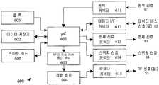
도 1을 참조하여 본 발명의 독창적 개념의 실시예에 따른 휴대형 소비자 전자(CE) 기기(100)에 구현될 수 있는 기능적 및 구조적 구성요소들에 대한 소개가 제공될 것이고 상세히 설명될 것이다.An introduction to the functional and structural components that may be implemented in a portable consumer electronic (CE) device 100 according to an embodiment of the inventive concept of the present invention will be provided and described in detail with reference to FIG. 1.
도 1은 본 발명의 실시예에 따른 휴대형 소비자 전자(CE) 기기(100)의 구현을 기초로 하여 일 예의 사용자 단말을 개략적으로 도시한다. 도 1의 블록도는 도해의 방법으로 셀룰러 단말의 원리 구조적 디자인을 묘사한다. 본 발명이 도 1에 도시된 예시적인 휴대형 CE 기기(100)에 제한되지 않는다는 것에 유의할 필요가 있다. 오히려, 본 발명이 특히 셀룰러 전화기, 스마트 폰, 개인휴대 정보단말(PDA) 및 유사한 사용자 단말을 포함한 어떤 종류의 휴대형 사용자 단말로 운용 가능하다는 것이 이해되어야만 한다.1 schematically illustrates an example user terminal based on an implementation of a portable consumer electronic (CE) device 100 in accordance with an embodiment of the present invention. The block diagram of FIG. 1 depicts the principle structural design of a cellular terminal in the manner of illustration. It should be noted that the present invention is not limited to the exemplary portable CE device 100 shown in FIG. Rather, it should be understood that the present invention is operable with any kind of portable user terminal, especially including cellular telephones, smart phones, personal digital assistants (PDAs) and similar user terminals.
도시된 휴대형 CE 기기(100)는 전형적으로 중앙 또는 모바일 처리 유닛(CPU; 510), 데이터 및 애플리케이션 저장기(520)(이는 내부적 데이터 및 애플리케이션 저장기일 수 있다), 오디오 입력/출력(I/O) 수단(550)을 포함한 입력/출력 수단, 입력 제어기(Ctrl; 560)가 있는 키패드 그리고 디스플레이 제어기(Ctrl; 570)가 있는 디스플레이를 포함한다.The illustrated portable CE device 100 typically includes a central or mobile processing unit (CPU) 510, a data and application store 520 (which may be an internal data and application store), audio input / output (I / O). Input / output means, including means 550, a keypad with an input controller Ctrl 560, and a display with a display controller Ctrl 570.
휴대형 CE 기기(100)의 동작은 사용자에게 기능성을 제공하는 것에 의해 CE 기기(100)의 기능, 특징 및 기능성을 제어하는 운영 체계 또는 어떤 기본 제어 애플리케이션을 전형적으로 기초로 하여 중앙 처리 유닛(CPU)/모바일 처리 유닛(MPU; 510)에 의해 통상적으로 제어된다. 휴대형 CE 기기(100)에 내부적으로 배치될 수 있는 데이터 및 애플리케이션 저장기(520)는, 운영 체계, 하나 이상의 애플리케이션, 애플리케이션 데이터, 그리고 예를 들어 구성/셋업 데이터, 콘택트 정보, 메시징 정보, 달력 정보, 멀티미디어 데이터 등을 포함한 사용자 데이터를 저장하고 제공하는데 소용된다. 데이터 및 애플리케이션 저장기(520)는 판독 전용 메모리(ROM) 및 랜덤 액세스 메모리(RAM) 중의 적어도 하나로서 구현되고 알려진 데이터 저장기 기술들을 기초로 하여 실현된다. 디스플레이 및 디스플레이 제어기(Ctrl; 570)는 중앙/모바일 처리 유닛(CPU/MPU; 510)에 의해 전형적으로 제어되고, 특히 CE 기기(100)의 기능, 특징 및 기능성을 사용자가 사용할 수 있게 하는 (그래픽) 사용자 인터페이스(UI)를 포함하여 사용자에게 정보를 제공한다. 키패드 및 키패드 제어기(Ctrl; 560)는 사용자가 정보를 입력할 수 있게 하기 위해 제공된다. 키패드를 통해 입력된 정보는 통상적으로 키패드 제어기(Ctrl)에 의해 처리 유닛(CPU/MPU; 510)에 공급되고, 이 처리 유닛은 전형적으로 입력 정보에 따라서 지시 및 제어 중 적어도 하나가 수행된다. 오디오 입력/출력(I/O) 수단(550)은 예를 들면 오디오 신호를 재생하기 위한 스피커 및 오디오 신호를 기록하기 위한 마이크로폰 중 적어도 하나를 포함한다. 처리 유닛(CPU/MPU; 510)은 오디오 데이터의 오디오 출력 신호들로의 전환 및 오디오 입력 신호들의 오디오 데이터로의 전환을 제어할 수 있는데, 예를 들어 오디오 데이터는 전송 및 저장을 위한 적당한 포맷을 가진다. 디지털 오디오의 오디오 신호들로의 그리고 그 역으로의 오디오 신호 전환은 예컨대 디지털 신호 처리기(DSP, 미도시)를 기초로 하여 구현된 디지털-아날로그 및 아날로그-디지털 회로에 의해 통상적으로 지원된다.The operation of the portable CE device 100 is typically based on an operating system or any basic control application that controls the functionality, features and functionality of the CE device 100 by providing functionality to the user. / Typically controlled by a mobile processing unit (MPU) 510. The data and application store 520, which may be disposed internally in the portable CE device 100, includes an operating system, one or more applications, application data, and configuration / setup data, contact information, messaging information, calendar information, for example. It is used to store and provide user data, including multimedia data. Data and application store 520 is implemented as at least one of read only memory (ROM) and random access memory (RAM) and is implemented based on known data store technologies. The display and display controller (Ctrl) 570 is typically controlled by a central / mobile processing unit (CPU / MPU) 510, in particular allowing the user to use the functionality, features and functionality of the CE device 100 (graphics Provide information to the user, including the user interface (UI). A keypad and keypad controller (Ctrl) 560 is provided to allow a user to enter information. Information input via the keypad is typically supplied to a processing unit (CPU / MPU) 510 by a keypad controller Ctrl, which typically performs at least one of instructions and control in accordance with the input information. The audio input / output (I / O) means 550 comprises, for example, at least one of a speaker for reproducing the audio signal and a microphone for recording the audio signal. The processing unit (CPU / MPU) 510 may control the conversion of audio data into audio output signals and the conversion of audio input signals into audio data, for example audio data in a suitable format for transmission and storage. Have Audio signal conversion of digital audio into audio signals and vice versa is typically supported by digital-analog and analog-digital circuitry implemented for example on the basis of a digital signal processor (DSP, not shown).
부가적으로, 본 발명의 실시예에 따른 휴대형 CE 기기(100)는, 셀룰러 안테나에 연결되고 상응하는 가입자 식별 모듈(SIM; 540)과 함께 동작 가능한 셀룰러 인터페이스(I/F; 580)를 포함할 수 있다. 셀룰러 인터페이스(I/F; 580)는 셀룰러 안테나로부터 신호들을 수신하며, 그 신호들을 복호화하며, 그것들을 복조하고 그것들을 기저 대역 주파수로 바꾸는 셀룰러 송수신기로서 배치구성된다. 셀룰러 인터페이스(580)는 무선(over-the-air) 인터페이스를 위해 제공되며, 공중 육상 이동 통신망(PLMN)의 상응하는 무선 접속망(RAN)과의 셀룰러 통신을 위해 가입자 식별 모듈(SIM; 540)에 관련하여 사용된다. 셀룰러 인터페이스(I/F; 580)의 출력은 그래서 중앙 처리 유닛(CPU; 510)에 의한 추가의 처리를 필요로 할 수 있는 데이터의 스트림으로 구성된다. 셀룰러 송수신기로서 배치구성된 셀룰러 인터페이스(I/F; 580)는 무선 접속망(RAN)에 전송될 데이터를 중앙 처리 유닛(CPU; 510)으로부터 무선(over-the-air) 인터페이스를 경유하여 수신한다. 그러므로, 셀룰러 인터페이스(I/F; 580)는 신호를 부호화하며, 변조하고, 사용되는 무선 주파수로 변환한다. 그러면 셀룰러 안테나는 결과적인 무선 주파수 신호를 공중 육상 이동 통신망(PLMN)의 상응하는 무선 접속망(RAN)에 전송한다. 셀룰러 인터페이스(580)는 일반 패킷 무선 서비스(GPRS) 및 EDGE(Enhanced Data for GSM Evolution) 중 적어도 하나, 범용 이통통신 시스템(UMTS), 또는 셀 방식 전화 통신 표준을 위한 어떠한 유사하거나 관련된 표준을 위해서라도 사용 가능하게 될 수 있는 2세대 디지털 셀룰러 네트워크 이를테면 이동통신 세계화 시스템(GSM)을 지원할 수 있다.Additionally, portable CE device 100 according to an embodiment of the present invention may include a cellular interface (I / F) 580 connected to a cellular antenna and operable with a corresponding subscriber identity module (SIM) 540. Can be. Cellular interface (I / F) 580 is configured as a cellular transceiver that receives signals from a cellular antenna, decodes the signals, demodulates them, and converts them to baseband frequencies. The
더군다나, 본 발명의 실시예에 따른 휴대형 CE 기기(100)는 또한 국소 데이터 인터페이스(I/F; 300)와 데이터 인터페이스(I/F; 590)를 포함하는데, 데이터 인터페이스(I/F; 590)는 그것에 연결된 하나 이상의 메모리 모듈과는 메모리 제어기 기능에 따라서 데이터 및 명령어들 중 적어도 하나를 상호교환하기에 적합하게 되는 것이 바람직하다. 그러나, 스마트 카드 모듈이 어떤 일정한 모듈들에 통합된 실시예들에서는, 트랜잭션을 위한 시간 요건을 확보하기 위해 국소 데이터 인터페이스(I/F; 300)에 직접 링크될 필요가 있다.Furthermore, the portable CE device 100 according to an embodiment of the present invention also includes a local data interface (I / F; 300) and a data interface (I / F; 590), the data interface (I / F) 590. Is preferably adapted to exchange at least one of the data and instructions with one or more memory modules connected thereto depending on the memory controller function. However, in embodiments where the smart card module is integrated into certain constant modules, it may need to be linked directly to the local data interface (I / F) 300 to ensure time requirements for the transaction.
구현된 무선 단거리 데이터 인터페이스(I/F; 300) 또는 무선 단거리 송수신기는 휴대형 CE 기기(100)가 어떤 상응하는 상대측 네트워크, 기지국 또는 상대측 수신기 또는 송수신기와의 국소 무선 데이터 통신을 할 수 있게 한다. 국소 데이터 인터페이스(I/F; 300)는 저 전력 무선 주파수(LPRF) 송수신기, 특히, 어떤 알려진 또는 장래의 RFID 통신 및 근접장 통신(NFC) 표준들을 각각 포함하는 무선 주파수 식별(RFID) 기술을 기초로 하여 실현될 수 있다.The implemented wireless short range data interface (I / F) 300 or wireless short range transceiver enables the portable CE device 100 to perform local wireless data communication with any corresponding partner network, base station or partner receiver or transceiver. Local Data Interface (I / F) 300 is based on radio frequency identification (RFID) technology, which includes low power radio frequency (LPRF) transceivers, in particular, some known or future RFID communication and near field communication (NFC) standards, respectively. Can be realized.
더욱이, 내부(착탈식 또는 통합형) 스마트 메모리 모듈(600) 및 외부 착탈식 스마트 메모리 모듈(600) 중 적어도 하나가 제공된다. 데이터 인터페이스(I/F; 590)는 착탈식 스마트 메모리 모듈들(600) 및 휴대형 CE 기기(100), 즉, 착탈식 스마트 메모리 모듈들(600) 및 그것의 동작을 제어하는 휴대형 CE 기기(100)의 CPU/MPU(510) 사이의 데이터 및 명령어 통신들을 인터페이싱하기 위해 소용된다. 데이터 인터페이스(I/F; 590)는 현재 또는 장차의 이 기술분야의 기술적 수준에서 이용 가능한 어떤 적합한 하드웨어 및 소프트웨어 인터페이스들 중 적어도 하나에 의해 확립될 수 있다. 스마트 메모리 모듈(600)은 멀티미디어 카드(MMC), 보안 데이터(SD) 또는 어떤 필적하는 메모리 모듈 표준에 따라서 구현될 수 있다. 본 발명의 실시예들에 따른 스마트 메모리 모듈(600)의 구현은 다음의 도면들에 관하여 더 상세히 아래에서 기술될 것이다.Moreover, at least one of an internal (removable or integrated)
게다가, 위에서 기술된 셀룰러 인터페이스(580)에 더하여 또는 그것의 대체물로서 하나 이상의 네트워크 인터페이스가 예시적인 휴대형 CE 기기(100)에 구현될 수 있다. 다수의 무선 네트워크 통신 표준들이 오늘날 이용 가능하다.In addition, one or more network interfaces may be implemented in the exemplary portable CE device 100 in addition to or as a substitute for the
예를 들어, 휴대형 CE 기기(100)는 어떤 IEEE 802.xx 표준, 무선 근거리 통신망(WLAN) 표준, 울트라 광대역(UWB) 표준, 와이-파이(Wi-Fi) 표준, 어떤 블루투스 표준(1.0 1.1 1.2 2.0 ER), 지그비(ZigBee)(무선 개인 영역 네트워크들(WPANs) 용), 적외선 데이터 접근(IRDA), 다른 어떤 현재 이용 가능한 표준들 및 어떤 장래의 무선 데이터 통신 표준들 중 적어도 하나에 따라서도 동작하는 하나 이상의 무선 네트워크 인터페이스를 구비할 수 있다. 더군다나, 예시적인 휴대형 CE 기기(100)에 구현된 네트워크 인터페이스는 (또한) 유선 네트워크 이를테면 이더넷 근거리 네트워크(LAN), 일반 교환 전화망(PSTN), 디지털 가입자 회선(DSL), 및 다른 현재 이용 가능한 및 장래의 표준들 중 적어도 하나를 지원할 수 있다.For example, the portable CE device 100 may include any IEEE 802.xx standard, wireless local area network (WLAN) standard, ultra wideband (UWB) standard, Wi-Fi standard, any Bluetooth standard (1.0 1.1 1.2). 2.0 ER), ZigBee (for Wireless Personal Area Networks (WPANs)), Infrared Data Access (IRDA), any other currently available standards, and any future wireless data communication standards. One or more wireless network interfaces may be provided. Moreover, the network interfaces implemented in the exemplary portable CE device 100 (also) may be (also) wired networks such as Ethernet local area network (LAN), general switched telephone network (PSTN), digital subscriber line (DSL), and other currently available and future applications. It may support at least one of the standards.
부가하여, 휴대형 CE 기기(100)는, 본 발명의 어떤 특정한 실시예들에서, 디지털 비디오 방송(DVB-T, DVB-H), 디지털 오디오 방송(DAB), 디지털 라디오 몬디알 레(DRM), 통합 서비스 디지털 비디오 방송-지상파(ISDB-T), 고화질 텔레비전 시스템 위원회(ATSC) 및 디지털 멀티미디어 방송(DMB-T) 기법들을 몇몇 예로 포함하는 방송 전송 서비스들에 휴대형 CE 기기(100)가 액세스하는 것을 허용하는 방송 수신기 인터페이스(미도시)를 구비할 수 있다.In addition, the portable CE device 100 may, in certain specific embodiments of the present invention, comprise digital video broadcasting (DVB-T, DVB-H), digital audio broadcasting (DAB), digital radio mondial (DRM), Integrated Services The portable CE device 100 accesses broadcast transmission services, including some examples of digital video broadcast-terrestrial (ISDB-T), high definition television system committee (ATSC) and digital multimedia broadcast (DMB-T) techniques. It may be provided with a broadcast receiver interface (not shown).
위에서 기술되고 도 1에 관하여 도시된 휴대형 CE 기기(100)는 본 발명의 실시예에 따른 전자 기기의 예시적인 실시예를 나타내는데, 그 전자 기기를 기초로 하여 본 발명의 독창적인 개념이 구현가능하다. 일반적으로, 특히 셀룰러 전화기, 개인휴대 정보단말(PDA), 포켓형 개인용 컴퓨터, 휴대형 개인용 컴퓨터, 커뮤니케이터 단말 또는 처리 능력이 있는 다른 어떤 (휴대형) 소비자 가전 제품(CE), RFID 기술로 동작 가능한 적당한 국소 무선 통신 모듈(300), 및 소비자 가전 제품(CE)에 접속 가능한 적당한 스마트 메모리 모듈(600)을 포함하여 어떤 전자 기기라도 본 발명에 따라 적용 가능하다.The portable CE device 100 described above and illustrated with respect to FIG. 1 represents an exemplary embodiment of an electronic device according to an embodiment of the present invention, on which the inventive concept of the present invention can be implemented. . Generally, in particular cellular telephones, personal digital assistants (PDAs), pocket personal computers, portable personal computers, communicator terminals or any other (portable) consumer electronics (CE) capable of processing, suitable local radios operable with RFID technology. Any electronic device is applicable in accordance with the present invention, including the
도 1에 도시된 구성요소들 및 모듈들은 휴대형 CE 기기(100)에서 별도의 개개의 모듈들로서, 또는 그것들의 어떠한 조합으로도 통합될 수 있다. 휴대형 CE 기기(100)의 하나 이상의 구성요소 및 모듈은 시스템 온 어 칩(SoC)을 형성하게 중앙/모바일 처리 유닛(CPU/MPU)과 통합될 수 있다. 그런 시스템 온 어 칩(SoC)은 단일 칩으로 컴퓨터 시스템의 모든 구성요소를 통합할 수 있다. 시스템 온 어 칩(SoC)은 디지털, 아날로그, 혼합 신호, 그리고 자주 무선 주파수 기능들도 포함할 수 있다. 대표적인 응용 분야는 특히 크기와 전력 소비 제한을 억제하는 내장형 시스템들 및 휴대형 시스템들이다. 그런 시스템 온 어 칩(SoC)은 전형적으로는 서로 다른 태스크들을 수행하는 다수의 집적 회로(IC)들로 구성된다. 이것들은 마이크로프로세서(CPU/MPU), 메모리(RAM: 임의 접근 메모리, ROM: 판독 전용 메모리), 하나 이상의 범용 비동기 송수신기(UART), 하나 이상의 직렬/병렬/네트워크 포트, 직접 메모리 액세스(DMA) 제어기 칩, 그래픽 처리 유닛(GPU), 디지털 신호 처리기(DSP) 등을 포함한 하나 이상의 구성요소를 포함할 수 있다. 반도체 기술의 최근의 개선은 초 대규모 집적(VLSI) 집적 회로에 복잡도가 증가하는 것을 허용하여, 시스템의 모든 구성요소들을 단일 칩에 통합하는 것을 가능하게 하였다.The components and modules shown in FIG. 1 may be integrated as separate individual modules in the portable CE device 100, or in any combination thereof. One or more components and modules of the portable CE device 100 may be integrated with a central / mobile processing unit (CPU / MPU) to form a system on chip (SoC). Such a system-on-a-chip (SoC) can integrate all the components of a computer system into a single chip. System-on-a-chip (SoC) can also include digital, analog, mixed-signal, and often radio frequency functions. Typical applications are particularly embedded systems and portable systems that limit size and power consumption constraints. Such a system-on-a-chip (SoC) typically consists of multiple integrated circuits (ICs) that perform different tasks. These include microprocessors (CPU / MPU), memory (RAM: random access memory, ROM: read-only memory), one or more general purpose asynchronous transceivers (UART), one or more serial / parallel / network ports, direct memory access (DMA) controllers. It may include one or more components, including a chip, a graphics processing unit (GPU), a digital signal processor (DSP), and the like. Recent advances in semiconductor technology have allowed for increased complexity in ultra-large scale integrated (VLSI) integrated circuits, enabling the integration of all the components of a system into a single chip.
다음 실시예들은 스마트 메모리 모듈(600)과 스마트 메모리 모듈(600)의 국소 무선 통신 인터페이스(300)와의 상호운용의 실시예들을 예시할 것이다.The following embodiments will illustrate embodiments of interoperation of the
도 2a 및 2b를 참조하면, 본 발명의 실시예들에 따른 스마트 메모리 모듈(600)의 개략적인 블록도들이 도시된다. 스마트 메모리 모듈(600)은 제어용 회로, 즉 마이크로제어기(μC; 601)에 의해 제어될 수 있는데, μC는 데이터 저장기(602)에 연결된다. 데이터 저장기는 디지털 정보, 데이터, 데이터 레코드 등을 저장하기 위해 제공된다. 데이터 저장기는 판독 및 기록 접근을 가능하게 하는 플래시 임의 접근 메모리(RAM) 또는 판독 접근만 가능한 판독 전용 메모리일 수 있다. 일반적으로, 데이터 저장기(602)는 어떤 현재 또는 장래의 데이터 저장 기술에 따라서도 구현될 수 있다. 숙련된 자들은 데이터 저장기의 구현이 본 발명의 범위 밖에 있다는 것을 인정할 것이다. 한편으로는, 데이터 저장기는 데이터 판독 및 데이터 기록 중 적어도 하나를 위해 데이터 인터페이스(I/F) 커넥터(612)를 경유하여 액세스될 수 있는데, 데이터 인터페이스(I/F) 커넥터(612)는 스마트 메모리 모듈(600)을 휴대형 CE 기기(100)의 데이터 인터페이스(I/F; 590)의 상응하는 커넥터에 연결할 수 있다. 다른 한편으로는, 데이터 저장기는 또한 데이터 판독 및 데이터 기록 중 적어도 하나를 위해 RFID 회로와 RFID 로직을 각각 경유하여 액세스될 수 있다. 판독 및 기록 접근 중 적어도 하나는 어떤 전류라도 또는 어떤 RFID 기술 표준에 따라서도 사용 가능하다.2A and 2B, schematic block diagrams of a
RFID 로직과 RFID 전송 프로토콜들의 구현들에 관련한 세부사항들은 본 발명의 범위 밖에 있다. 본 발명이 어느 특정 RFID 기술 및 전송 프토토콜 중 적어도 하나에 제한되지 않는다는 것이 이해되어야만 한다.Details relating to implementations of RFID logic and RFID transmission protocols are outside the scope of the present invention. It should be understood that the present invention is not limited to at least one of any particular RFID technology and transmission protocol.
RFID 로직을 포함한 RFID 기술 기반 통신 회로(603)에 의해 생성된 무선 주파수 신호는 안테나 커넥터(615)에 의하여 휴대형 CE 기기(100)에 공급된다. 안테나 신호는 다음 도면들에 관해서 아래에 기술된 실시예들에 관련하여 상세히 기술될 것이다. 도 2a를 참조하면, RFID 기술 기반 통신 회로(603)에 의해 생성된 무선 주파수 신호는 안테나 커넥터(615)에 직접 공급되는 반면, 도 2b를 참조하면, RFID 기술 기반 통신 회로(603)에 의해 생성된 무선 주파수 신호는 정합 회로(604)를 경유하여 안테나 커넥터(615)에 공급된다. 정합 회로의 동작은 다음 도면들에 관해서 아래에 기술된 실시예에 관련하여 상세히 기술될 것이다.The radio frequency signal generated by the RFID technology based
원리상, RFID 기술 기반 통신 회로(603)는 데이터 저장기(602)로부터 읽은 데이터를 나타내는 데이터 신호들을 스마트 메모리 모듈(600)의 μC(601)로부터 수신하도록 그리고 그 데이터 신호들을 무선주파수 기반 대역 주파수에 삽입하도록 배치구성되는데, 결과적인 변조된 무선 주파수 신호는 안테나 커넥터(615)를 경유하여 무선 주파수 안테나에 의해 전송되기 위해 제공된다. 데이터 저장기(602)의 구현에 의존하여, RFID 기술 기반 통신 회로(603)는 또한 하나 이상의 데이터 신호를 생기게 하는 복조를 위해 변조된 무선 주파수 신호를 안테나 커넥터(615)를 경유하여 수신하도록 배치구성될 수 있다. 이 데이터 신호는 μC(601)에 공급된다. 수신되고 복조된 데이터 신호들은 μC(601)에 명령하기 위한 명령어들 및 데이터 저장기(602)에 기록될 데이터 정보 중 적어도 하나를 나타낼 수 있다. μC(601) 및 RFID 기술 기반 통신 회로(603) 각각의 동작을 위해 요구된 클록 신호는 클록 발생기(605)에 의해 제공될 수 있거나 또는 RFID 기술 기반 통신 회로(603)에 공급된 무선 주파수 신호로부터 생성될 수 있다. RFID 로직은 어떤 알려진 또는 장래의 RFID 기술에 따르는 트랜스폰더 기능성을 가지는 RFID 트랜스폰더, 어떤 알려진 또는 장래의 RFID 기술에 따르는 판독기 기능성을 가지는 RFID 판독기, 또는 어떤 알려진 또는 장래의 RFID 기술에 따르는 트랜스폰더 및 판독기 기능성을 가지는 RFID 모듈로서 배치구성될 수도 있다.In principle, the RFID technology based
전력공급 커넥터(611)가 스마트 메모리 모듈(600)에 전기 에너지를 공급하기 위해 제공된다. 전력공급 커넥터(611)는 휴대형 CE 기기의 전력 공급기, 즉 배터리 및 재충전가능 축전기 중 적어도 하나에 연결될 수 있다. 본 발명의 대체 실시예에 따르면, 스마트 메모리 모듈(600)에 대한 전력은 외부 전원으로부터 제공된다는 점에 유의할 필요가 있다. 이 실시예에서, 스마트 메모리 모듈(600)은 휴대형 CE 기기가 전력을 공급받지 않는 상황에서 동작 가능할 수도 있다. 게다가, 본 발명의 실시예들에 따르면, 존재 신호 커넥터(613) 및 스위칭 신호 커넥터(614) 중 적어도 하나는 존재 신호뿐 아니라 안테나 스위칭 신호를 휴대형 CE 기기에 제공하기 위해 배치구성될 수 있다. 존재 신호와 안테나 스위칭 신호는 다음의 도면들에 관해서 기술된 아래 실시예에 관련하여 상세히 기술될 것이다.A
본 발명의 실시예에 따르면, 데이터 저장기(602) 또는 최소한 그것의 일 부분은 보안된/보호된 메모리일 수 있다. 그런 보호된 메모리는 전형적으로는 기밀 데이터와 정보 각각을 저장하기 위해 배치구성된다. 전형적인 기밀 정보는 디지털 지불 트랜잭션 또는 디지털 티켓 정보를 허용하는 정보이다. 데이터 저장기(602) 또는 그것의 보호된 메모리 부분을 기초로 하여 구현된 보호된 메모리는 그 속에 저장된 기밀 디지털 정보의 관점에서 관련되는 보안 및 프라이버시 측면들을 보장하기 위해 고려되어야만 하는 보안 요건들을 충족시키는데 특히 적합하다. 이 기술분야의 숙련된 자들은 기밀 디지털 정보 이를테면 위에서 정의된 바와 같은 디지털 티켓 데이터와 디지털 지불 데이터의 취급이, 서비스 제공자가 당해 디지털 정보의 발행 권한과 수락 권한 양쪽 다에 관련하는 경우에, 사용자 관점에서 뿐 아니라 서비스 제공자 관점에서 보안 및 프라이버시 측면들의 영향을 받는다는 것이 인정할 것이다. 보안 요건들은 데이터 저장기(602)의 보호된 메모리 또는 보호된 메모리 부분에 저장된 데이터의 암호화 및 해독 중 적어도 하나를 가능하게 하는 어떤 암호 기술에 의해 달성될 수 있다. 게다가, 이 보안 요건들은 또한 접근 제어 메커니즘들에 의해, 예컨대 공개 키 기술이사용 가능한 인증에 의해 이루어질 수 있다. 위에 간략히 기술된 바와 같이 보호된 메모리의 배치구성은 이 기술분야에서 알려진 것이고 본 발명의 범위 밖에 있다는 것에 유의할 필요가 있다. 본 발명은 데이터 저장기(602)의 어느 특정 실시예로 제한되는 것으로 이해될 수는 없다.According to an embodiment of the invention, the
보호된 메모리는 스마트 메모리 모듈(600)에 포함되는 스마트 카드 모듈(606)에 의해 제공될 수 있다. 스마트 카드 모듈(606)은 그것에 강요되어야만 하는 위에서 기술된 보안 요건들을 충족시켜, 트랜잭션 관련 데이터 이를테면 신용 카드 데이터, 현금(money) 카드 데이터, 전자식 티켓 데이터 등의 저장을 허용할 수 있다. 스마트 카드 모듈(606)은 그러므로 보안 요건들이 충족되게 하는 암호 로직들, 인증 메커니즘 등을 포함할 수 있다. 스마트 카드 모듈(606)에 포함되는 보안 메커니즘들은 사설 또는 표준화된 보안 기술에 기초를 둘 수 있다. 각각의 서비스 제공자(예컨대 신용 카드 트랜젝션 서비스 제공자, 뱅크, 티켓팅 서비스 제공자, 공공 운송 서비스 제공자 등)은 자신의 사양서에 따라서 스마트 카드 모듈(606)을 구현할 수 있다. 그런 스마트 카드 모듈(606) 또는 스마트 카드들에 관한 상세한 구현예들 및 요건들은 본 발명의 범위 밖에 있고 본 발명은 그것의 어느 특정 구현예에도 한정되지 않는다는 것에 유의할 필요가 있다.The protected memory may be provided by the
이 기술분야의 숙련된 자들은 스마트 메모리 모듈(600)의 구성요소들이 예시의 방법을 위해 제공된다는 것을 인정할 것이다. 본 발명은 스마트 메모리 모듈(600)의 어느 특정한 구현에라도 제한되지 않는다. 특히, 마이크로제어기(μC; 601), 클록 발생기(605), 데이터 저장기(602), 스마트 카드 모듈(606) 및 RFID 로직 중 적어도 하나는 하나 이상의 통합 회로를 기초로 하여 구현될 수 있다. 스마트 메모리 모듈(600)의 동작을 제어하는 것은 스마트 메모리 모듈을 제어하고 동작하기 위해 디자인된 어떤 제어용 회로에 의해서 마찬가지로 달성될 수 있다.Those skilled in the art will appreciate that the components of the
발명의 가능한 실시예에 따라서, 스마트 메모리 모듈은 핸드헬드 이동 전화기에 착탈식으로 연결될 수 있는데, 거기서 보안 요건은 핸드헬드 이동 전화기를 가동하기 위해 개인 식별 번호(PIN)를 입력하는 사용자에 의해 달성된다. 스위칭 온을 위해 요구되는 PIN은, 핸드헬드 이동 전화기의 SIM에 고유하게 관련된다. 그래서 이동 전화기가 스위치 오프된 때 또는 예컨대 화면 보호 모드로부터 전화기가 가동될 때 PIN 입력은 이동 전화기 및 그것에 부착된 구성요소들을 비인가 사용으로부터 보호한다.According to a possible embodiment of the invention, the smart memory module can be detachably connected to a handheld mobile phone, where security requirements are achieved by a user entering a personal identification number (PIN) to run the handheld mobile phone. The PIN required for switching on is uniquely related to the SIM of the handheld mobile phone. The PIN input thus protects the mobile phone and its attached components from unauthorized use when the mobile phone is switched off or when for example the phone is activated from a screen protection mode.
도 3a 및 3b를 참조하면, 본 발명의 실시예에 따라 스마트 메모리 모듈(600)을 수용하기 위한 스마트 메모리 모듈 인터페이스(700)가 있는 휴대형 CE 기기(100)의 개념 블록도 뿐 아니라 상응하는 인터페이스(700)에 끼워진 스마트 메모리 모듈(600)이 있는 휴대형 CE 기기(100)의 개념 블록도가 도시된다. 간결함을 위하여, 도 3a 및 3b에 보인 블록도들은 본 발명의 개념 및 실시예들에 따라서 구성요소들 및 하위 구성요소들이 감축된다.3A and 3B, a conceptual block diagram of a portable CE device 100 having a smart
도 3a를 참조하면, 도 1에 관해서 기술했던 무선 인터페이스(I/F; 300)는 제어기/인터페이스 구성요소(304)를 포함한 하위 구성요소들에 의해 구현되는데, 그것은 휴대형 CE 기기(100)의 CPU/MPU(510)로부터 예를 들어 데이터 버스를 경유하여 데이터를 수신한다. 수신된 데이터는 베이스밴드 주파수로 변조되고, 상대측 무선 인터페이스에 무선으로 전송하기 위해 근접장 통신(NFC) 회로(305)에 의해 상응하는 안테나(310)에 공급된다. 더군다나, 안테나(310)를 통해 수신된 데이터 반송 무선 주파수(RF) 신호들은, 인터페이스(304)를 경유하여 휴대형 CE 기기(100)의 CPU/MPU(510)에 의해 처리하기 위해, 수신된 RF 신호들에 삽입된 데이터의 복조 및 준비를 위해 NFC 회로(305) 및 제어기/인터페이스(304)에 공급된다. 이 기술분야의 숙련된 자들은 제어기/인터페이스(304)와 NFC 회로(305)가 도 1의 무선 인터페이스(300)에 의해 구성될 수 있다는 것을 인정할 것이다.Referring to FIG. 3A, the air interface (I / F) 300 described with respect to FIG. 1 is implemented by subcomponents including the controller /
이 기술분야의 숙련된 자들은 여기에서 제시된 NFC 회로(305)가 단지 예시적인 것일 뿐임을 다음의 설명을 기초로 하여 인식할 것이다. 그 NFC 회로는 어떤 알려진 또는 장래의 RFID 기술에 따라 데이터 통신을 가능하게 하는 어느 RFID 기술 기반 통신 회로를 나타내는 것이라고 이해되어야만 한다.Those skilled in the art will recognize based on the following description that the
본 발명의 실시예에 따르면, 안테나 신호 스위칭 모듈(320)(간결함을 위해 다음에서 안테나 스위치(320)로 지정됨)은 NFC 회로(305)와 안테나(310) 사이에 개재된다. 안테나 스위칭 신호(S4)에 따라서, 안테나 스위치(320)는 스마트 메모리 모듈 인터페이스(700) 및 안테나(310)에 배치된 안테나 커넥터뿐 아니라 NFC 회로(305) 및 안테나(310) 사이를 연결하는 신호를 확립하는 것을 허용한다. 스마트 메모리 모듈 인터페이스(700)의 안테나 커넥터는 인터페이스(700)에 끼워지게 미리 정해져 있는 스마트 메모리 모듈(600)의 안테나 커넥터(615)와 함께 사용 가능하다. 이것은, 바꾸어 말하면, 안테나 스위치(320)가 휴대형 CE 기기(100)의 안테나(310)와 이 휴대형 CE 기기의 NFC 회로(305) 사이에서 뿐 아니라 스마트 메모리 모듈(600)의 RFID 기술 기반 통신 회로(603) 및 휴대형 CE 기기(100)의 안테나(310) 사이에서 선택적인 신호 접속을 허용한다는 것을 의미한다.According to an embodiment of the invention, an antenna signal switching module 320 (designated herein as
도 3b를 참조하면, 스마트 카드 모듈(600)은 인터페이스(700)에 끼워지고 안테나 스위칭 신호(S4)가 인터페이스(700)에서 스마트 메모리 모듈(600)의 존재를 검출하는 것에 응답하여 생성되는데, 이 안테나 스위칭 신호는, 본 발명의 실시예 에 따르면, 스마트 카드 모듈(600)(즉 그것의 μC(601))에 의해 생성될 수 있고 위에서 주어진 설명에 따라 안테나 스위치(320)의 스위칭 위치를 조작하기 위해 안테나 스위치(320)에 공급된다. 안테나 스위칭 신호(S4)의 생성은 스마트 카드 모듈(600)에 의해 휴대형 CE 기기(590)의 데이터 인터페이스(I/F; 590)로부터 데이터 인터페이스 커넥터(612)를 경유하여 수신된 하나 이상의 명령에 따라서 제어될 수 있거나, 또는 스마트 카드 모듈(600)(즉 그것의 μC(601))에 의해 자체적으로 생성될 수 있다. 안테나 스위치(320)의 스위칭 동작은 도 7의 흐름도에 관해서 더 상세하게 기술될 것인데, 그 도면은 본 발명의 실시예에 따른 안테나 스위치(320)로 사용 가능한 동작 순서를 도시한다.Referring to FIG. 3B, the
일반적으로, 스마트 메모리 모듈 인터페이스(700)는 본 발명의 실시예에 따라 도 2a 및 2b에 관해서 위에서 도시된 스마트 메모리 모듈(600)의 커넥터들과 함께 사용 가능한 하나 이상의 커넥터를 제공한다. 본 발명의 실시예에 따라서, 메모리 모듈 인터페이스(700)는 스마트 메모리 모듈(600)의 수용을 위해 슬롯으로서 디자인된다. 본 발명이 스마트 메모리 모듈 인터페이스(700)의 어느 특정한 기계적 디자인에 제한되지 않고, 기계적 디자인이 특히 어떤 슬롯 배치구성, 어떤 홀더/지지 배치구성, 어떤 플러그 소켓 연결, 어떤 케이블 조인트 배치구성 등을 포함할 수 있다는 것에 유의할 필요가 있다. 스마트 메모리 모듈(600)은 휴대형 CE 기기(100)와는 데이터 및 명령들 중 적어도 하나를 상호교환하기 위한 메모리 컨트롤러 능력을 특히 가지는 데이터 인터페이스(590)에 연결될 수 있다.In general, the smart
도 4a 및 4b를 참조하면, 본 발명의 실시예들에 따라 스마트 메모리 모 듈(600)을 수용하기 위한 스마트 메모리 모듈 인터페이스(700)가 있는 휴대형 CE 기기(100)의 개념 블록도 뿐 아니라 상응하는 인터페이스(700)에 끼워진 스마트 메모리 모듈(600)이 있는 휴대형 CE 기기(100)의 개념 블록도가 도시된다. 간결함을 위하여, 도 4a 및 4b에서 보인 블록도들은 본 발명의 개념 및 실시예들에 따라서 구성요소들 및 하위 구성요소들이 감축된다.4A and 4B, a conceptual block diagram as well as a corresponding block diagram of a portable CE device 100 having a smart
도 4a를 참조하면, 도 1에 관해서 기술했던 무선 인터페이스(I/F; 300)는 제어기/인터페이스 구성요소(304)를 포함하여 하위 구성요소들에 의해 구체화되는데, 제어기/인터페이스 구성요소(304)는 휴대형 CE 기기(100)의 CPU/MPU(510)로부터 예를 들어 데이터 버스를 경유하여 데이터를 수신한다. 수신된 데이터는 베이스밴드 주파수로 변조되고, 상대측 무선 인터페이스에 무선으로 전송되기 위해 근접장 통신(NFC) 회로(305)에 의해 상응하는 안테나(310)에 공급된다. 더군다나, 안테나(310)를 통해 수신된 데이터 반송 무선 주파수(RF) 신호들은, 인터페이스(304)를 경유한 휴대형 CE 기기(100)의 CPU/MPU(510)에 의한 처리를 위하여, 수신된 RF 신호들에 삽입된 데이터의 복조 및 준비를 위해 NFC 회로(305) 및 제어기/인터페이스(304)에 공급된다. 이 기술분야의 숙련된 자들은 제어기/인터페이스(304)와 NFC 회로(305)가 도 1의 무선 인터페이스(300)에 의해 구성될 수 있다는 것을 인정할 것이다.Referring to FIG. 4A, the air interface (I / F) 300 described with respect to FIG. 1 is embodied by subcomponents, including the controller /
발명의 실시예에 따르면, 안테나 신호 스위칭 모듈(320)(간결함을 위하여 다음에서 안테나 스위치(320)로 지정됨)은 NFC 회로(305) 및 안테나(310) 사이에 개재된다. 안테나 스위칭 신호(S4*)에 따라, 안테나 스위치(320)는 NFC 회로(305) 및 안테나(310) 사이의 신호 연결뿐 아니라 스마트 메모리 모듈 인터페이스(700) 및 안테나(310)에 배치구성되는 안테나 커넥터를 확립되게 한다. 스마트 메모리 모듈 인터페이스(700)의 안테나 커넥터는 인터페이스(700)에 끼워지게 미리 정해져 있는 스마트 메모리 모듈(600)의 안테나 커넥터(615)와 함께 사용 가능하다. 이것은, 안테나 스위치(320)가 휴대형 CE 기기(100)의 안테나(310)와 휴대형 CE 기기의 NFC 회로(305) 사이에서 뿐 아니라 스마트 메모리 모듈(600)의 RFID 기술 기반 통신 회로(603) 및 휴대형 CE 기기(100)의 안테나(310) 사이에서 선택적인 신호 연결을 허용한다는 것을 의미한다.According to an embodiment of the invention, an antenna signal switching module 320 (designated herein as
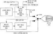
도 4b를 참조하면, 스마트 카드 모듈(600)은 인터페이스(700)에 끼워지고 휴대형 CE 기기(100)의 제어기/인터페이스(304)에 의해 생성된 안테나 스위칭 신호(S4*)는 위에 주어진 설명에 따라 안테나 스위치(320)의 스위칭 위치를 조작하기 위해 안테나 스위치(320)에 공급된다. 안테나 스위칭 신호(S4)*의 생성은 전형적으로는 휴대형 CE 기기(590)의 CPU/MPU(510)로 제어되거나, 또는 무선 인터페이스(300)의 제어기 인터페이스(304)에 의해 자체적으로 생성될 수 있다. 제어기 인터페이스(304)에는 존재 신호(S3)가 공급되는데, 이 존재 신호는 본 발명의 개념에 따라서 RFID 로직 및 기능성을 가지는 스마트 메모리 모듈(600)의 존재를 나타낸다. 존재 신호(S3)는 본 발명의 실시예에 따라 스마트 메모리 모듈(600)에 의해 생성될 수 있고, 스마트 메모리 모듈(600)로부터 그것의 상응하는 존재 신호 커넥터(612)를 경유하여 수신될 수 있다. 안테나 스위칭 신호(S4*)는 스마트 메모리 모듈(600)로부터의 존재 신호(S3)에 의존하여 휴대형 CE 기기(100)의 제어기/인터페이스(304)에 의해 생성될 수 있다. 안테나 스위치(320)의 스위칭 동작은 도 7의 흐름도에 관해서 더 상세하게 기술될 것인데, 도 7은 본 발명의 실시예에 따라 안테나 스위치(320)와 함께 사용 가능한 동작 순서를 도시한다.Referring to FIG. 4B, the
도 5 및 6을 참조하면 본 발명의 실시예들에 따른 정합 회로들의 다른 배치구성들을 도시하는 개념 블록도들이 도시된다. 가능하면 NFC 회로(305)와 안테나(310) 뿐 아니라 RFID 기술 기반 통신 회로(603) 및 안테나(310)의 특성들의 최적의 조절을 얻기 위하여, 정합 회로는 전기적 특성들(전기 특성치들, 전기 매개변수들), 예를 들어 전기 임피던스, 전파 임피던스, 유도도(inductivity) 및 추가의 전기적 값들 중 적어도 하나를 조정하기 위해 제공된다. 정합 회로(306)에 의해 얻어진 특성 조절은 NFC 회로(305)뿐 아니라 안테나(310) 및 RFID 기술 기반 통신 회로(603) 사이에 개재된 안테나 스위치(320)의 특성들을 고려한다. 본 발명의 실시예에 따르면, 정합 회로(306)의 동작은 조절 매개변수들을 통해 제어 가능할 수 있다. 조절 매개변수들은 회로(305, 603), 안테나 스위치(320) 및 안테나(310)의 개개의 특성들에 따라서 정합 회로(306)에 제공된다.5 and 6, conceptual block diagrams illustrating other arrangements of matching circuits in accordance with embodiments of the present invention are shown. Where possible, in order to obtain optimal control of the characteristics of the RFID technology-based
일반적으로, 하나 이상의 정합 회로에 의한 특성들의 조절은 개선된 신호 대 잡음 비(SNR), 개선된 RF 신호 수신 감도, 및 개선된 전송 강도를 포함한 그룹 중의 적어도 하나를 다룬다. 신호 경로(커넥터들을 포함) 및 로직들의 레이아웃에서의 차이들은 정합회로/정합회로들에 의해 보정되는 것이다.In general, adjustment of the characteristics by one or more matching circuits deals with at least one of the group including improved signal-to-noise ratio (SNR), improved RF signal reception sensitivity, and improved transmission strength. Differences in the signal path (including connectors) and the layout of the logics are to be corrected by the matching circuit / matching circuits.
도 5를 참조하면, 정합 회로(306)는 각각 안테나 스위치(320) 및 RFID 기술 기반 통신 회로(603)뿐 아니라 NFC 회로(305) 사이의 RF 신호들의 각각의 신호 경로에 개재된다. 제1 정합 회로(306)는 RFID 기술 기반 통신 회로(603) 및 안테나(310) 사이에서 특성 조절에 소용된다. 스마트 메모리 모듈(600)은 도 2a에 도시되고 그것에 관련하여 상세히 기술된 실시예에 따라서 배치구성될 수 있다.5, matching
도 6을 참조하면, 공통 정합 회로(306)는 RF 신호의 신호 경로에서 안테나 스위치(320)와 안테나(310) 사이에서 삽입된다. 공통 정합 회로(306)는 RFID 기술 기반 통신 회로(603) 및 안테나(310) 사이에서 뿐 아니라 NFC 회로(305) 및 안테나(310) 사이에서 특성 조절을 위해 소용된다. 스마트 메모리 모듈(600)은 도 2b에 도시되고 그것에 관련하여 상세히 기술된 실시예에 의거하여 배치구성될 수 있다.Referring to FIG. 6, a
하나 이상의 조절 매개변수에 의한 정합 회로(306)의 구성 능력은 도 5 및 6에 관해서 위에서 기술된 예시적인 실시예들 둘 다에서 사용될 수 있다. 조절 매개변수들은 NFC 회로(305), 제어기/인터페이스(304), RFID 기술 기반 통신 회로(603) 및 μC(601) 중 적어도 하나에 의해 제공될 수 있다. 조절 매개변수들은 예를 들어 제작 시험 동안에 수행되는 교정(calibration) 측정을 기초로 하여 결정될 수 있다.The ability to configure the
도 7을 참조하면, 본 발명의 실시예에 따른 동작 순서를 도시하는 개념적인 흐름도가 묘사된다. 동작 순서는 시작하고 제1동작에서 위에 기술된 실시예들 중의 하나에 따른 스마트 메모리 모듈(600)의 존재가 점검된다. 동작 S100에서, 스마트 메모리 모듈(600)의 존재는 검출된다. 이 검출은 본 발명의 실시예에 따른 스마트 메모리 모듈(600)의 존재를 나타내는 존재 신호(S3)를 수신하는 것에 의해 이행된다. 동작 S110에서, 구해진 존재 신호(S3)의 상태는 점검된다. 어떤 스마트 메모리 모듈(600)도 존재하지 않는 경우, 동작 순서는 존재 신호(S3)를 구하기 위한 동작 으로 되돌아간다. 그렇지 않으면, 동작 순서는 계속된다.Referring to FIG. 7, a conceptual flow diagram depicting an operation sequence in accordance with an embodiment of the present invention is depicted. The operation sequence starts and the first operation is checked for the presence of the
본 발명의 실시예에 따른 스마트 메모리 모듈(600)의 부재(absence) 동안, 안테나 스위치의 스위칭 상태는 안테나(310) 및 NFC 회로(305)를 결합하도록 설정된다.During the absence of the
동작 S120에서, 안테나 스위칭 신호(S4, S4*)가 생성되어야만 하는지가 점검된다. 스위칭 신호(S4 또는 S4*)의 생성은 사용자와의 상호작용에(대화) 의거하여 휴대형 CE 기기(100)에 의해, 스마트 메모리 모듈(600)에 의해, 예컨대 스위치를 지시하는 명령들로서 휴대형 CE 기기에 해석될 수 있는 정보를 전송하는 상대측 기기에 의해, RFID 기술 기반 통신 회로(603) 및 NFC 회로(305) 중 적어도 하나에 의해 지시, 수행 또는 개시될 수 있다. 이 기술분야의 숙련된 자들은 안테나 스위칭 신호가 생성되게 하는 열거된 이벤트들 또는 기준들이 완전하지 않고 단지 본 발명의 일부 예의 실시예들을 제공할 뿐임을 인정할 것이다.In operation S120, it is checked whether the antenna switching signals S4 and S4 * should be generated. The generation of the switching signal S4 or S4 * is carried out by the portable CE device 100 on the basis of the interaction (conversation) with the user, by the
사용자와의 상호작용에 관하여, 안테나 스위치(320)를 가능한 스위칭 상태들 중의 하나로 바꾸기 위한 안테나 스위칭 신호(S4, S4*)는 사용자 입력에 응답하여 생성된다. 사용자는 RFID 기술 기반 통신 회로(603) 또는 NFC 회로(305)가 안테나(310)와 더불어 사용 가능하도록 안테나 스위치(320)의 스위칭 상태를 정의하는 것이 가능하다. 안테나 스위치(320)의 스위칭 상태를 정의하기 위한 기능성은, 스위칭을 위해 사용자에게 상응하는 입력을 제공하는 (그래픽) 사용자 인터페이스의 수단과 더불어 사용 가능할 수 있다.With respect to interaction with the user, antenna switching signals S4 and S4 * for changing
상대측 기기에 관하여, 안테나 스위치의 스위칭과 그래서 스위칭 신호(S4, S4*)의 생성은, 상대측 기기에 의해 요구, 지시 또는 명령된다. 상대측 기기, 예컨대 입출금 기계(teller machine), 판매 시점 관리 시스템(point of sale), 티켓팅 기계 등은 휴대형 CE 기기(100)에 미리 정해 두었던 메시지를 발행할 수 있다. 상대측 기기 및 휴대형 CE 기기(100) 사이에서 데이터 상호교환을 위해 어떤 데이터 인터페이스 또는 데이터 연결을 경유하여 전송될 수 있는 이 메시지의 수신에 의거하여, 휴대형 CE 기기(100)에는 상대측 기기에 의해 나타내어진 스위칭 상태로 스위칭하기 위하여 스위칭 신호(S4, S4*)를 생성하라는 요구 또는 명령이 알려진다. 상대측 기기, 예컨대 판매 시점 관리 시스템은 예를 들어 메시지를 NFC 접속, 블루투스 접속, 셀룰러 통신 접속 등을 경유하여 휴대형 CE 기기(100)에 전송한다. 도 1에 관해서 기술된 어떤 데이터 통신 인터페이스라도 사용될 수 있다는 점에 유의할 필요가 있다. 메시지 수신과 구문분석(parsing)에 의거하여 휴대형 CE 기기(100)는, 안테나(310) 및 트랜잭션 관련 정보 이를테면 신용 카드 데이터와 현금 카드 데이터를 포함하는 스마트 메모리 모듈(600) 사이에 RF 신호 경로를 확립하기 위해 안테나 스위치(320)를 스위칭하는 스위칭 신호(S4, S4*)를 생성한다. RF 신호 경로의 확립 후, 판매 시점 관리 시스템은 트랜잭션 관련 정보를 검색하기 위해 질문 신호를 RFID 기술 기반 통신 회로(603)에 전송한다.With respect to the counterpart device, switching of the antenna switch and thus generation of the switching signals S4 and S4 * are requested, instructed or commanded by the counterpart device. The counterpart device, such as a teller machine, a point of sale system, a ticketing machine, or the like, may issue a message previously determined in the portable CE device 100. Based on the reception of this message, which may be transmitted via any data interface or data connection for data interchange between the counterpart device and the portable CE device 100, the portable CE device 100 may be represented by the counterpart device. A request or command is known to generate the switching signals S4 and S4 * to switch to the switching state. The counterpart device, such as a point of sale system, transmits a message to the portable CE device 100 via, for example, an NFC connection, a Bluetooth connection, a cellular communication connection, and the like. It should be noted that any data communication interface described with respect to FIG. 1 may be used. Based on message reception and parsing, the portable CE device 100 establishes an RF signal path between the
휴대형 CE 기기를 참조하면, 안테나 스위치(320)의 스위칭 상태는 휴대형 CE 기기(100)와 휴대형 CE 기기(100)와 함께 사용 가능한 하나 이상의 애플리케이션 각각에 의해 독자적으로 조작된다. 예를 들면, 능동 애플리케이션은 어떤 상대측 기기로부터 데이터를 검색하거나, 데이터를 어떤 상대측 기기에 전송하거나, 또는 어떤 상대측 기기에 의한 검색용 데이터를 제공하기 위해 NFC 회로(305) 또는 RFID 기술 기반 통신 회로(603)를 채용하는 안테나 스위치(320)의 스위치 상태를 제어할 수 있다. 채용되는 로직이 무엇인지에 의존하여, 스위칭 상태는 능동 애플리케이션에 의해 제어 가능하다.Referring to the portable CE device, the switching state of the
스마트 메모리 모듈에 관하여, 안테나 스위칭 신호(S4, S4*)는 스마트 메모리 모듈(600) 또는 그것의 어떤 구성요소에 의해 생성된다. 예를 들어, 안테나 스위치(320)의 스위칭은 스마트 메모리 모듈(600)을 휴대형 CE 기기(100)의 상응하는 인터페이스(700)에 끼우는 것을 의미하게 될 수 있다. 더군다나, 안테나 스위치(320)의 스위칭은 스마트 메모리 모듈(600) 또는 그것의 어떤 구성요소를 동작하도록 설정하거나 스마트 메모리 모듈(600)의 어떤 구성요소를 가동시키는 것에 의거하여 스마트 메모리 모듈(600) 또는 그것의 어떤 구성요소에 의해 개시될 수 있다. 예를 들면, RFID 기술 기반 통신 회로(603) 또는 스마트 카드(606)는 스마트 메모리 모듈(600)을 휴대형 CE 기기(100)에 연결하는 데이터 인터페이스(590)를 통한 하나 이상의 명령의 수신에 의해 가동될 수 있다. 하나 이상의 명령은 스마트 메모리 모듈(600)의 하나 이상의 구성요소, 특히 RFID 기술 기반 통신 회로(603) 또는 스마트 카드(606)를 가동(활성화)시키기 위해 인증 및 접근 제어 중 적어도 하나에 관련한 시퀀스들을 포함할 수 있다. 가동의 결과로, 스마트 메모리 모듈은 휴대형 CE 기기(100)의 스마트 메모리 모듈(600) 및 안테나(310) 사이에 신호 경로를 확립하기 위해 안테나 스위칭 신호(S4)를 생성한다.With respect to the smart memory module, the antenna switching signals S4 and S4 * are generated by the
NFC 로직에 관하여, 스위칭 신호(S4, S4*)는 예를 들어 안테나(310)를 경유한 RF 신호의 수신에 의거하여 생성되는데, RF 신호는 원래 스마트 메모리 모듈(600)의 RFID 기술 기반 통신 회로(603)에 의해 수신되도록 의도된 것이다. 주파수, 변조 구조, 삽입 데이터, 삽입 명령 등이 지정될 수 있는 그런 RF 신호의 수신에 의거하여, NFC 회로(305) 및 제어기/인터페이스(304) 중 적어도 하나는 휴대형 CE 기기(100)의 스마트 메모리 모듈(600) 및 안테나(310) 사이에 신호 경로를 확립하기 위해 안테나 스위칭 신호(S4, S4*)의 생성을 개시한다.With regard to NFC logic, the switching signals S4 and S4 * are generated based on the reception of an RF signal via, for example, the
RFID 로직에 관하여, 스위칭 신호(S4, S4*)는, 원래는 휴대형 CE 기기(100)의 NFC 회로(305)에 의해 수신될 것이 의도된 RF 신호의 안테나(310)를 경유한 수신에 의거하여 생성된다. 주파수, 변조 구조, 삽입 데이터, 삽입 명령 등이 지정될 수 있는 그런 RF 신호의 수신에 의거하여, 스마트 메모리 모듈(600)은 휴대형 CE 기기(100)의 NFC 회로(305) 및 안테나(310) 사이에서 신호 경로를 확립하기 위해 안테나 스위칭 신호(S4, S4*)의 생성을 개시한다.With regard to the RFID logic, the switching signals S4, S4 * are based on reception via the
정황(context) 정보에 관하여, 어떤 정황 정보라도 휴대형 CE 기기에 이용할 수 있을 수 있는데, 정황 정보는 예를 들어 휴대형 CE 단말의 사용자가 현재 가게, 쇼핑몰, 은행 홀, 영화관 내에서 입출금 기계, 티켓팅 기계, 판매 시점 관리 시스템 등 근처에 있음을 나타내는 위치/장소 관련 정보를 포함한다. 정황 정보의 출처 및 정황 정보의 전송/수신 방식에 무관하게, 휴대형 CE 단말과 함께 사용 가능한 애플리케이션은 애플리케이션-정의 신호 경로를 확립하기 위해 안테나 스위칭 신호(S4, S4*)를 생성하는 것이 사용자에게 유익하다는 것을 정황 정보에 기초하여 결정할 수 있다.With regard to contextual information, any contextual information may be available for a portable CE device, for example, where the user of the portable CE terminal is present in a store, shopping mall, bank hall, movie theater, deposit or withdrawal machine, ticketing machine. Location / location-related information, indicating that the system is near a point of sale, such as a point of sale system. Regardless of the context information source and the manner in which the context information is transmitted / received, applications that can be used with portable CE terminals benefit the user from generating antenna switching signals (S4, S4 *) to establish application-defined signal paths. Can be determined based on the context information.
요약하여, 안테나 스위치(320)의 스위칭은 스마트 메모리 모듈의 존재, 휴대형 CE 기기에 제공된 정황 정보에 기초한 것들인 사용자-개시 기능성/애플리케이션 선택(사용자에 의해 입력된 하나 이상의 UI 명령에 응답하여) 및 자동화된 기능성/애플리케이션 선택 중 적어도 하나에 기초할 수 있다. 이 기술분야의 숙련된 자들은 위에서 주어진 예들이 안테나 스위치(320)의 상황에 적합한 스위칭을 가능하게 하는 어떠한 방식으로도 결합될 수 있다는 것을 인정할 것이다. 안테나 스위칭은 휴대형 CE 기기, 그것의 구성요소들, 스마트 메모리 모듈 및 그것의 어떤 구성요소들 중 적어도 하나에 의해 검출되는 스위칭 기준/이벤트에 응답하는 기준/이벤트 구동(driven) 스위칭이라고 부를 수 있다.In summary, the switching of the
생성된 안테나 스위칭 신호(S4, S4*)의 존재로, 안테나 스위치는 동작 S140으로 동작된다. 스위칭 전에, 휴대형 CE 기기(100)의 사용자는 예를 들어 사용자에게 의되된 스위칭을 수락 또는 거절할 것을 요구하는 통지 디스플레이에 의해 의도된 스위칭에 관해 알릴 수도 있다. 통지에 의거하여, 사용자는 스위칭 동작을 해제하거나 거절하는 것이 허용된다.With the presence of the generated antenna switching signals S4 and S4 *, the antenna switch is operated in operation S140. Prior to the switching, the user of the portable CE device 100 may be informed about the intended switching, for example by a notification display requiring the user to accept or reject the intended switching. Based on the notification, the user is allowed to release or reject the switching operation.
동작 S150 및 160에서, 안테나 스위치(320)의 스위칭은 해제되고 NFC 회로(305) 및 안테나(310) 사이의 신호 경로는 확립된다. 그렇지 않으면, 안테나 스위치(320)의 스위칭은 해제되고 안테나(310) 및 스마트 메모리 모듈(600) 뿐 아니라 그것의 RFID 기술 기반 통신 회로(603) 사이의 신호 경로는 확립된다. 그러므로, NFC 회로(305)와 RFID 기술 기반 통신 회로(603)는 각각 데이터/신호 교환을 위해 사용 가능하다.In operations S150 and 160, the switching of the
신호 경로의 확립에 조합하여, 확립된 신호 경로를 경유하여 결합된 안테나 및 로직의 전기적 특성들은 로직은 조절될 수 있다. 이 조절은 (레이아웃 특유) 기본 특성을 가지는 안테나 및 (디자인 특유) 기본 특성들도 각각 가지는 로직들 사이의 상호 운용을 달성해야만 한다. 특성들의 조정 또는 정합은 가능한 한 최적으로 되어야만 한다. 특성들의 조절은 신호 경로에 개재된 하나 이상의 고정 정합 회로에 의해 얻어질 수 있다. 고정 정합 회로들은 전형적으로는 하나의 로직과 하나의 안테나의 특성들을 정합하기 위해 제공된다. 대신에, 그런 정합 회로들은 정합 회로들의 정합/조절 동작을 결정하는 조절 매개변수들에 따라서 구성가능할 수 있다. 조절 매개변수들은 정합에 적합한 로직 및 조절 매개변수들을 관련시키는 테이블에 저장될 수 있다. 조절 매개변수들은 미리 정의될 수 있거나, 로직에 의해 제공될 수 있거나, 또는 테스트 신호 생성 및 분석에 의해 얻어질 수 있다.In combination with the establishment of the signal path, the electrical characteristics of the antenna and logic coupled via the established signal path may be logic adjusted. This adjustment must achieve interoperability between the antenna having the (layout specific) basic characteristics and the logics each having the (design specific) basic characteristics as well. The adjustment or matching of the properties should be as optimal as possible. Adjustment of the characteristics can be obtained by one or more fixed matching circuits interposed in the signal path. Fixed matching circuits are typically provided to match the characteristics of one logic and one antenna. Instead, such matching circuits may be configurable in accordance with adjustment parameters that determine the matching / adjusting behavior of the matching circuits. The adjustment parameters may be stored in a table relating logic and adjustment parameters suitable for matching. Adjustment parameters may be predefined, provided by logic, or obtained by test signal generation and analysis.
데이터 교환 동작의 완료 후, 안테나 스위치(320)는 동작 S190에서 디폴트 스위칭 상태로 복귀할지도 모른다. 동작 S200에서, 동작 순서는 동작 순서의 반복된 수행을 위해 동작 S100으로 복귀하거나 또는 종료한다.After completion of the data exchange operation, the
이 기술분야의 숙련된 자들은 본 발명의 독창적인 개념이 휴대형 CE 기기에 탈착 가능하게 연결된 하나의 스마트 메모리 모듈에 제한되지 않는다는 것을 위에 주어진 설명을 기초로 하여 인식할 것이다. 안테나 스위치(320)는 2개를 넘는 RF 신호 단말들을 휴대형 CE 기기의 공통 안테나(310)에 연결된 공통 안테나 단말에 스위칭하기 위해 배치구성될 수 있다. 더군다나, 위에 기술된 본 발명의 실시예들은 휴대형 CE 기기(100)에 의해 포함된 NFC 로직과 스마트 메모리 모듈(600)에 의해 포함된 RFID 로직을 기초로 하여 운용되었다. RFID 로직뿐 아니라 NFC 로직은 RFID 기술을 기초로 하여 데이터 통신을 지원하는 통신 로직 유닛들의 예시적인 실시예들을 나타낸다. 본 발명에 따르는 독창적인 개념은 스마트 메모리 모듈(600)에 의해 포함된 그리고 CE 기기(100)에 의해 포함된 어떤 RFID 기술 기반 로직들에 의해 실현될 수 있다.Those skilled in the art will appreciate based on the description given above that the inventive concept of the present invention is not limited to one smart memory module detachably connected to a portable CE device. The
이 기술분야의 숙련된 자들에게는 본 발명의 독창적인 개념이 많은 수의 방법들로 구현될 수 있다는 것이 명백하다. 본 발명과 그것의 실시예들은 그래서 위에 기술된 예들인 구체적인 실시예들에 제한되지 않고 대신 청구범위 내에서 가변할 수 있다.It will be apparent to those skilled in the art that the inventive concept of the invention can be implemented in a large number of ways. The invention and its embodiments are thus not limited to the specific embodiments that are the examples described above, but instead can vary within the scope of the claims.
Claims (35)
Translated fromKoreanApplications Claiming Priority (1)
| Application Number | Priority Date | Filing Date | Title |
|---|---|---|---|
| PCT/IB2005/001869WO2007003978A1 (en) | 2005-06-30 | 2005-06-30 | Device, module and method for shared antenna operation in a rfid technology based communication environment |
Publications (2)
| Publication Number | Publication Date |
|---|---|
| KR20080025698A KR20080025698A (en) | 2008-03-21 |
| KR101002042B1true KR101002042B1 (en) | 2010-12-17 |
Family
ID=37604120
Family Applications (1)
| Application Number | Title | Priority Date | Filing Date |
|---|---|---|---|
| KR1020077030610AExpired - Fee RelatedKR101002042B1 (en) | 2005-06-30 | 2005-06-30 | Devices, modules and methods for the operation of antennas shared in RF technology-based communication environment |
Country Status (7)
| Country | Link |
|---|---|
| US (1) | US9098787B2 (en) |
| EP (1) | EP1897231B1 (en) |
| KR (1) | KR101002042B1 (en) |
| CN (1) | CN101194432B (en) |
| AT (1) | ATE443379T1 (en) |
| DE (1) | DE602005016730D1 (en) |
| WO (1) | WO2007003978A1 (en) |
Cited By (1)
| Publication number | Priority date | Publication date | Assignee | Title |
|---|---|---|---|---|
| CN104777799A (en)* | 2014-01-09 | 2015-07-15 | 红米国际旅馆有限公司 | Service management method and computer system thereof |
Families Citing this family (47)
| Publication number | Priority date | Publication date | Assignee | Title |
|---|---|---|---|---|
| KR100694378B1 (en)* | 2005-09-22 | 2007-03-12 | 주식회사 팬택 | Mobile communication terminal including RDF reader and its transmission / reception method |
| FR2892212A1 (en)* | 2005-10-17 | 2007-04-20 | St Microelectronics Sa | NFC READER HAVING PASSIVE OPERATING MODE WITH LOW POWER CONSUMPTION |
| KR100736051B1 (en)* | 2005-10-17 | 2007-07-06 | 삼성전자주식회사 | Apparatus and method for providing additional digital multimedia broadcasting function |
| US20070218837A1 (en)* | 2006-03-14 | 2007-09-20 | Sony Ericsson Mobile Communications Ab | Data communication in an electronic device |
| US7702282B2 (en)* | 2006-07-13 | 2010-04-20 | Sony Ericsoon Mobile Communications Ab | Conveying commands to a mobile terminal through body actions |
| US8018913B2 (en)* | 2006-09-29 | 2011-09-13 | Broadcom Corporation | Method and system for sharing components in a time division multiplex wireless system |
| US8116678B2 (en)* | 2007-06-08 | 2012-02-14 | Vivotech, Inc. | Methods, systems and computer program products for interacting with ISO 14443-4 and MIFARE® applications on the same wireless smart device during a common transaction |
| GB0713614D0 (en)* | 2007-07-12 | 2007-08-22 | Icera Inc | Smart card module |
| TW200906151A (en)* | 2007-07-31 | 2009-02-01 | Chunghwa Telecom Co Ltd | Electronic wallet Combi-SIM card architecture combining mobile device non-contact transceiver |
| KR100930821B1 (en)* | 2007-11-14 | 2009-12-10 | (주)애니쿼터스 | RF shared connection module for mobile communication terminal and RF communication method using same |
| US8083140B1 (en) | 2008-02-05 | 2011-12-27 | Sprint Communications Company L.P. | System and method of over-the-air provisioning |
| TWI363511B (en)* | 2008-02-26 | 2012-05-01 | Mstar Semiconductor Inc | Wireless communication apparatus and method thereof |
| KR20090100497A (en) | 2008-03-20 | 2009-09-24 | 한국전자통신연구원 | Idle control system and its control method |
| US8662401B2 (en)* | 2008-07-25 | 2014-03-04 | First Data Corporation | Mobile payment adoption by adding a dedicated payment button to mobile device form factors |
| CN101354739B (en)* | 2008-08-25 | 2010-12-29 | 国民技术股份有限公司 | Method for controlling radio frequency SIM card communication distance in virtue of label recognition and communication system thereof |
| US8086269B2 (en)* | 2008-09-12 | 2011-12-27 | A-Men Technology Corporation | Modular structure to expand and enhance subscriber identity module card functionality |
| US8706588B1 (en)* | 2008-10-20 | 2014-04-22 | Sprint Communications Company L.P. | System and method of provisioning confidential information via a mobile device |
| EP2377291B1 (en)* | 2008-12-12 | 2018-01-24 | Nxp B.V. | Portable mobile communication device and method of controlling near field communication |
| US8060449B1 (en) | 2009-01-05 | 2011-11-15 | Sprint Communications Company L.P. | Partially delegated over-the-air provisioning of a secure element |
| US8682261B2 (en) | 2009-02-13 | 2014-03-25 | Qualcomm Incorporated | Antenna sharing for wirelessly powered devices |
| US8768845B1 (en) | 2009-02-16 | 2014-07-01 | Sprint Communications Company L.P. | Electronic wallet removal from mobile electronic devices |
| FR2942582B1 (en)* | 2009-02-24 | 2011-03-11 | Neowave | PORTABLE DEVICE, ESPECIALLY OF THE USB KEY TYPE, PROVIDED WITH MULTIPLE SELECTIVE CONTACTLESS COMMUNICATION INTERFACES |
| US20100274713A1 (en)* | 2009-04-24 | 2010-10-28 | Tun-Ping Wang | Wireless Trading System And Method Of Using The Same |
| FR2945694B1 (en)* | 2009-05-13 | 2011-07-29 | Oberthur Technologies | ELECTRONIC ENTITY WITH MICROCIRCUIT CARD READER OPERATION AND ASSOCIATED METHOD |
| US20110059692A1 (en)* | 2009-09-08 | 2011-03-10 | Electronics And Telecommunications Research Institute | Communications device using near field |
| CN101778492B (en)* | 2009-12-29 | 2013-08-07 | 深圳市远望谷信息技术股份有限公司 | Method for radio frequency identification of mobile communication terminal and equipment thereof |
| KR101090476B1 (en) | 2010-04-21 | 2011-12-08 | 엘지전자 주식회사 | Home Appliance and operating method |
| US8068011B1 (en) | 2010-08-27 | 2011-11-29 | Q Street, LLC | System and method for interactive user-directed interfacing between handheld devices and RFID media |
| US9402278B2 (en)* | 2010-11-26 | 2016-07-26 | Wireless Dynamics, Inc. | Multi-mode communication system for a mobile phone |
| CN103093161A (en)* | 2011-10-28 | 2013-05-08 | 成都高新区尼玛电子产品外观设计工作室 | Radio frequency identification devices (RFID) antenna and signal same-source dual-functional system |
| US8510381B1 (en) | 2012-02-14 | 2013-08-13 | Google Inc. | Sharing electronic resources with users of nearby devices |
| US8533266B2 (en)* | 2012-02-14 | 2013-09-10 | Google Inc. | User presence detection and event discovery |
| US9520638B2 (en) | 2013-01-15 | 2016-12-13 | Fitbit, Inc. | Hybrid radio frequency / inductive loop antenna |
| CN104077617B (en)* | 2013-03-28 | 2020-08-28 | 西门子公司 | Authentication method and device |
| TW201528148A (en)* | 2014-01-06 | 2015-07-16 | Pegatron Corp | Wearable apparatus and operating method thereof |
| US9196964B2 (en) | 2014-03-05 | 2015-11-24 | Fitbit, Inc. | Hybrid piezoelectric device / radio frequency antenna |
| DE102014108586A1 (en) | 2014-06-18 | 2015-12-24 | Phoenix Contact Gmbh & Co. Kg | Parameterizable automation technology device |
| JP6305289B2 (en)* | 2014-09-12 | 2018-04-04 | 株式会社東芝 | Mobile device |
| US10819395B1 (en) | 2014-09-24 | 2020-10-27 | Amazon Technologies, Inc. | Inductance powered packaging to configure a device |
| CN106326967B (en)* | 2015-06-29 | 2023-05-05 | 四川谦泰仁投资管理有限公司 | RFID chip with interactive switch input port |
| US10057642B2 (en)* | 2015-10-06 | 2018-08-21 | Comcast Cable Communications, Llc | Controlling the provision of power to one or more devices |
| CN106228101A (en)* | 2016-08-04 | 2016-12-14 | 邦奇智能科技(上海)股份有限公司 | A kind of NFC/RFID smart machine rapid configuration system and method |
| CN108880572A (en)* | 2018-07-06 | 2018-11-23 | 漳州高新区远见产业技术研究有限公司 | A kind of NFC and RFID two-in-one antenna control system |
| US10997483B2 (en) | 2019-06-12 | 2021-05-04 | Stmicroelectronics, Inc | NFC antenna switch |
| US12093921B2 (en)* | 2021-06-10 | 2024-09-17 | Shopify Inc. | Method and system for active NFC payment device management |
| CN113989962B (en)* | 2021-10-27 | 2023-07-07 | 维沃移动通信有限公司 | Access control identification control method and related equipment |
| CN118368014B (en)* | 2024-06-20 | 2024-09-03 | 恩平市奥新电子科技有限公司 | Sound console with gear memory function |
Citations (1)
| Publication number | Priority date | Publication date | Assignee | Title |
|---|---|---|---|---|
| KR100548411B1 (en)* | 2003-10-08 | 2006-02-02 | 엘지전자 주식회사 | Device and method for improving matching characteristics of mobile communication terminal |
Family Cites Families (13)
| Publication number | Priority date | Publication date | Assignee | Title |
|---|---|---|---|---|
| TW319939B (en) | 1993-12-13 | 1997-11-11 | Thomson Consumer Electronics | |
| US5988510A (en)* | 1997-02-13 | 1999-11-23 | Micron Communications, Inc. | Tamper resistant smart card and method of protecting data in a smart card |
| AU2002211424A1 (en)* | 2000-10-04 | 2002-04-15 | American Express Travel Related Services Company, Inc. | System and method for providing feedback in an interactive payment system |
| EP1342289B1 (en)* | 2000-10-11 | 2010-05-19 | Alfred E. Mann Foundation for Scientific Research | Improved antenna for miniature implanted medical device |
| EP1365353A3 (en)* | 2002-05-20 | 2004-03-03 | Quadnovation, Inc. | Contactless transaction card and adapter therefor |
| JP4047715B2 (en)* | 2002-12-11 | 2008-02-13 | 株式会社東海理化電機製作所 | Security system and portable device for security system |
| JP2004215225A (en) | 2002-12-17 | 2004-07-29 | Sony Corp | Communication system, communication method, and data processing device |
| KR100514685B1 (en)* | 2003-05-13 | 2005-09-13 | 주식회사 팬택앤큐리텔 | Handset for embodying function of time shift and method thereof |
| JP4218463B2 (en) | 2003-08-11 | 2009-02-04 | ソニー株式会社 | Wireless communication apparatus and wireless communication system |
| KR100584328B1 (en)* | 2003-10-07 | 2006-05-26 | 삼성전자주식회사 | Mobile terminal circuit combined with radio frequency identification tag and wireless identification method in mobile terminal |
| US7421244B2 (en)* | 2004-12-13 | 2008-09-02 | Broadcom Corporation | Method and system for mobile receiver antenna architecture for handling various digital video broadcast channels |
| US20060203757A1 (en)* | 2005-03-11 | 2006-09-14 | Spotwave Wireless Inc. | Adaptive repeater system |
| KR20060112301A (en) | 2005-04-25 | 2006-10-31 | 삼성전자주식회사 | Security method and device using text message |
- 2005
- 2005-06-30KRKR1020077030610Apatent/KR101002042B1/ennot_activeExpired - Fee Related
- 2005-06-30CNCN2005800499714Apatent/CN101194432B/ennot_activeExpired - Fee Related
- 2005-06-30EPEP05756054Apatent/EP1897231B1/ennot_activeExpired - Lifetime
- 2005-06-30DEDE602005016730Tpatent/DE602005016730D1/ennot_activeExpired - Lifetime
- 2005-06-30USUS11/922,653patent/US9098787B2/ennot_activeExpired - Fee Related
- 2005-06-30WOPCT/IB2005/001869patent/WO2007003978A1/ennot_activeApplication Discontinuation
- 2005-06-30ATAT05756054Tpatent/ATE443379T1/ennot_activeIP Right Cessation
Patent Citations (1)
| Publication number | Priority date | Publication date | Assignee | Title |
|---|---|---|---|---|
| KR100548411B1 (en)* | 2003-10-08 | 2006-02-02 | 엘지전자 주식회사 | Device and method for improving matching characteristics of mobile communication terminal |
Cited By (1)
| Publication number | Priority date | Publication date | Assignee | Title |
|---|---|---|---|---|
| CN104777799A (en)* | 2014-01-09 | 2015-07-15 | 红米国际旅馆有限公司 | Service management method and computer system thereof |
Also Published As
| Publication number | Publication date |
|---|---|
| KR20080025698A (en) | 2008-03-21 |
| CN101194432B (en) | 2012-09-05 |
| US20090093272A1 (en) | 2009-04-09 |
| CN101194432A (en) | 2008-06-04 |
| US9098787B2 (en) | 2015-08-04 |
| ATE443379T1 (en) | 2009-10-15 |
| EP1897231B1 (en) | 2009-09-16 |
| WO2007003978A1 (en) | 2007-01-11 |
| EP1897231A1 (en) | 2008-03-12 |
| DE602005016730D1 (en) | 2009-10-29 |
Similar Documents
| Publication | Publication Date | Title |
|---|---|---|
| KR101002042B1 (en) | Devices, modules and methods for the operation of antennas shared in RF technology-based communication environment | |
| US9913077B2 (en) | Switching between multiple coupling modes | |
| EP3211567B1 (en) | Mobile radio communication apparatus | |
| US9172786B2 (en) | Apparatus and method for controlling functions of a mobile phone using near field communication (NFC) technology | |
| KR100862953B1 (en) | Radio frequency identification RF-ID based discovery for short range radio communication with reader device having transponder functionality | |
| US8761664B2 (en) | Near field connection establishment | |
| KR100718012B1 (en) | Battery pack of mobile communication terminal and NFC communication method using same | |
| EP2034428B1 (en) | NFC capable mobile communication device | |
| US20070155430A1 (en) | External device for mobile communication terminal and NFC method using the same | |
| US20130217325A1 (en) | Securing of a telecommunication device equipped with a near-field communication module | |
| US9634727B2 (en) | NFC architecture | |
| EP2355368B1 (en) | Telecommunication component and wireless communication system for coupling a cellular mobile telecommunication device to an NFC terminal | |
| US9124312B2 (en) | Communication device, reader/writer device, communication system, and communication method | |
| CN103378880A (en) | Service terminal, NFC equipment and near field communication method | |
| EP2360987B1 (en) | Device and method for coupling a cellular telecommunication device to an NFC terminal | |
| WO2011092289A1 (en) | Device and method for coupling a cellular telecommunication device to an nfc terminal | |
| KR100854526B1 (en) | Detector logic and wireless recognition device and method for enhancing terminal operation | |
| KR100827806B1 (en) | A mobile communication terminal and a method of using a mobile payment service using the mobile communication terminal |
Legal Events
| Date | Code | Title | Description |
|---|---|---|---|
| A201 | Request for examination | ||
| PA0105 | International application | St.27 status event code:A-0-1-A10-A15-nap-PA0105 | |
| PA0201 | Request for examination | St.27 status event code:A-1-2-D10-D11-exm-PA0201 | |
| PG1501 | Laying open of application | St.27 status event code:A-1-1-Q10-Q12-nap-PG1501 | |
| E902 | Notification of reason for refusal | ||
| PE0902 | Notice of grounds for rejection | St.27 status event code:A-1-2-D10-D21-exm-PE0902 | |
| E13-X000 | Pre-grant limitation requested | St.27 status event code:A-2-3-E10-E13-lim-X000 | |
| P11-X000 | Amendment of application requested | St.27 status event code:A-2-2-P10-P11-nap-X000 | |
| P13-X000 | Application amended | St.27 status event code:A-2-2-P10-P13-nap-X000 | |
| E14-X000 | Pre-grant third party observation filed | St.27 status event code:A-2-3-E10-E14-opp-X000 | |
| E902 | Notification of reason for refusal | ||
| PE0902 | Notice of grounds for rejection | St.27 status event code:A-1-2-D10-D21-exm-PE0902 | |
| E14-X000 | Pre-grant third party observation filed | St.27 status event code:A-2-3-E10-E14-opp-X000 | |
| P11-X000 | Amendment of application requested | St.27 status event code:A-2-2-P10-P11-nap-X000 | |
| P13-X000 | Application amended | St.27 status event code:A-2-2-P10-P13-nap-X000 | |
| E701 | Decision to grant or registration of patent right | ||
| PE0701 | Decision of registration | St.27 status event code:A-1-2-D10-D22-exm-PE0701 | |
| GRNT | Written decision to grant | ||
| PR0701 | Registration of establishment | St.27 status event code:A-2-4-F10-F11-exm-PR0701 | |
| PR1002 | Payment of registration fee | St.27 status event code:A-2-2-U10-U12-oth-PR1002 Fee payment year number:1 | |
| PG1601 | Publication of registration | St.27 status event code:A-4-4-Q10-Q13-nap-PG1601 | |
| LAPS | Lapse due to unpaid annual fee | ||
| PC1903 | Unpaid annual fee | St.27 status event code:A-4-4-U10-U13-oth-PC1903 Not in force date:20131211 Payment event data comment text:Termination Category : DEFAULT_OF_REGISTRATION_FEE | |
| R18-X000 | Changes to party contact information recorded | St.27 status event code:A-5-5-R10-R18-oth-X000 | |
| PC1903 | Unpaid annual fee | St.27 status event code:N-4-6-H10-H13-oth-PC1903 Ip right cessation event data comment text:Termination Category : DEFAULT_OF_REGISTRATION_FEE Not in force date:20131211 | |
| R18-X000 | Changes to party contact information recorded | St.27 status event code:A-5-5-R10-R18-oth-X000 | |
| P22-X000 | Classification modified | St.27 status event code:A-4-4-P10-P22-nap-X000 |