KR101000531B1 - CC management system using wireless LAN that increases data transmission range - Google Patents
CC management system using wireless LAN that increases data transmission rangeDownload PDFInfo
- Publication number
- KR101000531B1 KR101000531B1KR1020080061212AKR20080061212AKR101000531B1KR 101000531 B1KR101000531 B1KR 101000531B1KR 1020080061212 AKR1020080061212 AKR 1020080061212AKR 20080061212 AKR20080061212 AKR 20080061212AKR 101000531 B1KR101000531 B1KR 101000531B1
- Authority
- KR
- South Korea
- Prior art keywords
- data
- cctv
- packet
- image data
- management system
- Prior art date
- Legal status (The legal status is an assumption and is not a legal conclusion. Google has not performed a legal analysis and makes no representation as to the accuracy of the status listed.)
- Expired - Fee Related
Links
Images


Classifications
- H—ELECTRICITY
- H04—ELECTRIC COMMUNICATION TECHNIQUE
- H04N—PICTORIAL COMMUNICATION, e.g. TELEVISION
- H04N7/00—Television systems
- H04N7/18—Closed-circuit television [CCTV] systems, i.e. systems in which the video signal is not broadcast
- H—ELECTRICITY
- H04—ELECTRIC COMMUNICATION TECHNIQUE
- H04N—PICTORIAL COMMUNICATION, e.g. TELEVISION
- H04N7/00—Television systems
- H04N7/18—Closed-circuit television [CCTV] systems, i.e. systems in which the video signal is not broadcast
- H04N7/181—Closed-circuit television [CCTV] systems, i.e. systems in which the video signal is not broadcast for receiving images from a plurality of remote sources
- H—ELECTRICITY
- H04—ELECTRIC COMMUNICATION TECHNIQUE
- H04N—PICTORIAL COMMUNICATION, e.g. TELEVISION
- H04N7/00—Television systems
- H04N7/18—Closed-circuit television [CCTV] systems, i.e. systems in which the video signal is not broadcast
- H04N7/183—Closed-circuit television [CCTV] systems, i.e. systems in which the video signal is not broadcast for receiving images from a single remote source
- H04N7/185—Closed-circuit television [CCTV] systems, i.e. systems in which the video signal is not broadcast for receiving images from a single remote source from a mobile camera, e.g. for remote control
Landscapes
- Engineering & Computer Science (AREA)
- Multimedia (AREA)
- Signal Processing (AREA)
- Closed-Circuit Television Systems (AREA)
- Mobile Radio Communication Systems (AREA)
- Two-Way Televisions, Distribution Of Moving Picture Or The Like (AREA)
Abstract
Translated fromKoreanDescription
Translated fromKorean본 발명은 다수의 CCTV를 이용한 촬영 대상 지역의 관리시스템에 관한 것으로서 더욱 상세하게는 촬영대상범위에 다수의 CCTV가 설치되어 종합적으로 관리되는 CCTV 관리시스템에 있어서 거리의 근접순서에 따라 순차적으로 CCTV가 촬영한 데이터를 전송하되 자신이 촬영한 촬영데이터와 타 CCTV의 촬영데이터를 인코딩하여 전송되도록 함으로써 유선 형태보다 용이하게 설치될 수 있으며 무선 형태의 데이터 전송 범위의 한계를 제거할 수 있는 데이터 전송 범위가 증대되는 무선랜을 이용한 CCTV 관리시스템에 관한 것이다.The present invention relates to a management system of a shooting target area using a plurality of CCTV, more specifically, in the CCTV management system that is installed in a plurality of CCTV in the shooting target range and comprehensively managed CCTV in sequence according to the close order of distance It transmits the captured data, but it can be installed more easily than the wired form by encoding the recorded data and the recording data of other CCTVs, and has a data transmission range that can remove the limitation of the wireless data transmission range The present invention relates to a CCTV management system using an increased WLAN.
일반적으로, 대도시에서는 치안이나 방범활동, 순찰, 쓰레기 무단투기, 주차위반 등을 위해 CCTV가 설치되어 운영되고 있다. 그러나, 이러한 CCTV가 대도시 전체에 대해 전면적으로 실시되는 것이 아니라 일부 자치단체에서 제한적인 목적으로 만 운영하고 있다. 예를 들어, 강남구에서는 치안을 목적으로 골목길에 고정식 CCTV를 설치하여 운영하고 있고, 서울시에서는 주차단속을 위해 길가에 CCTV를 설치하여 운영하고 있다. 또한, 구청에서는 쓰레기 무단투기를 단속하기 위해 일부 지역마다 CCTV를 설치하여 감시하고 있다.In general, CCTVs are installed and operated in large cities for security, security activities, patrols, illegal dumping, and parking violations. However, these CCTVs are not fully implemented in large cities but are operated by a limited number of municipalities for a limited purpose. For example, in Gangnam-gu, fixed CCTVs are installed on alleys for security purposes, while Seoul Metropolitan Government installs and operates CCTVs on roadsides for parking control. In addition, the ward office has installed CCTVs in some areas to monitor illegal dumping.
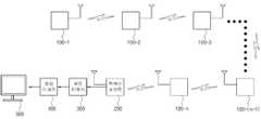
도 1은 종래 유선형태의 CCTV 관리 시스템의 구성도이다.1 is a block diagram of a conventional CCTV management system of the wired form.
CCTV는 유선 또는 무선 형태로 촬영데이터를 전송하는데, 유선 CCTV의 경우 도 1과 같이 영상을 압축하지 않은 상태에서 유선으로 셋탑박스 혹은 PC로 전달하여 여러 개의 영상을 동시에 디스플레이한다. 그리고 무선 CCTV의 경우에 있어서도 각각의 카메라는 영상데이터를 엑세스 포인트로 바로 전달한다. 이 경우 데이터의 전송거리는 카메라에서 엑세스 포인트까지 데이터를 송수신할 수 있는 거리와 같다. 일반적으로 무선랜은 10m~100m 까지 데이터를 전송할 수 있기 때문에 무선랜을 사용하는 무선 카메라는 이 범위 내에서 데이터를 송수신할 수 있다.CCTV transmits photographing data in a wired or wireless form, and in the case of wired CCTV, as shown in FIG. 1, multiple images are simultaneously displayed by transferring to a set-top box or a PC by wire without being compressed. And even in the case of wireless CCTV, each camera transfers the image data directly to the access point. In this case, the data transmission distance is equal to the distance that the data can be transmitted and received from the camera to the access point. In general, since a wireless LAN can transmit data from 10m to 100m, a wireless camera using a wireless LAN can transmit and receive data within this range.
따라서 유선 CCTV의 경우 설치과정이 복잡하고 촬영 대상 범위가 넓고 설치 대수가 많을수록 이러한 설치작업은 보다 어려워지며 무선 CCTV의 경우에도 데이터 전송범위의 한계에 의해 100m 범위를 벗어날 경우 엑세스 포인트를 추가로 설치하여야 하는 부담이 있어 시스템이 보다 복잡하고 비용이 증대되는 문제점이 있다.Therefore, in the case of wired CCTV, the installation process is complicated, the shooting range is wide, and the number of installations is more difficult, and the installation work becomes more difficult. In the case of wireless CCTV, if access is beyond 100m range due to the limitation of data transmission range, additional access point must be installed. There is a problem that the system is more complicated and the cost is increased.
본 발명은 상기의 문제점을 해결하기 위해 안출된 것으로서 촬영대상범위에 다수의 CCTV가 설치되어 종합적으로 관리되는 CCTV 관리시스템에 있어서 거리의 근접순서에 따라 순차적으로 CCTV가 촬영한 데이터를 전송하되 자신이 촬영한 촬영데이터와 타 CCTV의 촬영데이터를 인코딩하여 전송되도록 함으로써 유선 형태보다 용이하게 설치될 수 있으며 무선 형태의 데이터 전송 범위의 한계를 제거할 수 있는 데이터 전송 범위가 증대되는 무선랜을 이용한 CCTV 관리시스템을 제공함에 그 모적이 있다.The present invention has been made in order to solve the above problems, in the CCTV management system that is installed in a plurality of CCTVs in the shooting target range comprehensively managed to transmit the data photographed by CCTV sequentially according to the proximity of distance CCTV management using wireless LAN that can be installed more easily than wired type by encoding the recorded shooting data and the recording data of other CCTV and transmit the data transmission range that can remove the limitation of the wireless data transmission range The idea is to provide a system.
본 발명은 상기의 목적을 달성하기 위해 아래와 같은 특징을 갖는다.The present invention has the following features to achieve the above object.
본 발명은 무선랜 전송방식의 CCTV가 일정위치에 다수 설치되어 이의 촬영데이터를 전송받아 종합적으로 관리하는 CCTV 관리시스템에 있어서, 상기 CCTV 관리시스템은 촬영하여 관리하고자 하는 대상 범위 내에 설치되며 무선랜모듈이 장착되어 촬영한 데이터가 무선으로 송수신되는 다수의 CCTV와; 상기 CCTV로부터 촬영데이터를 전송받는 액세스 포인트와; 상기 액세스 포인트로부터 촬영 데이터를 전송받아 촬영 데이터 중 헤더 데이터를 제거한 압축 영상 데이터를 생성하는 패킷 디먹서와; 상기 패킷 디먹서로부터 압축 영상 데이터를 전송받아 압축된 영상 데이터를 디코딩하는 영상 디코더 및; 상기 영상 디코더로부터 디코딩된 영상 데이터를 전송받아 출력하는 디스플레이 수단을 포함하여 이루어지며, 상기 다수의 CCTV 간에는 액세스 포인트와 근접한 거리에 따라 이격된 기준으로 순서가 설정되고, 설정된 순서에 따라 가장 거리가 먼 최선순위 CCTV의 촬영 데이터를 가장 근접한 후순위 CCTV로 전송하며 촬영 데이터를 전송받은 해당 후순위 CCTV는 전송받은 촬영 데이터와 자신이 촬영한 촬영 데이터를 믹싱하여 이와 가장 근접한 후순위 CCTV로 전송함에 따라 액세스 포인트와 가장 근접한 CCTV가 모든 CCTV의 촬영 데이터를 믹싱하여 최종적으로 액세스 포인트로 믹싱된 촬영 데이터를 전송하되, 상기 CCTV는 목적 대상을 촬영하는 카메라 모듈과, 상기 카메라 모듈로부터 촬영된 데이터를 압축하는 영상 인코더와, 상기 영상 인코더로부터 압축된 영상 데이터를 전송받아 헤더 데이터를 부여하는 패킷 먹서와, 설정된 순서에 따라 영상데이터가 전송됨에 따라 가장 근접한 선순위 CCTV로부터 전송받은 촬영 데이터 중 헤더 데이터를 제거하여 압축 영상 데이터를 추출하고 이를 패킷 먹서로 전송함에 따라 패킷 먹서에 의해 해당 영상 데이터와 가장 근접한 선순위 CCTV 영상 데이터가 믹싱되도록 하는 패킷 디먹서와, 상기 패킷 먹서로부터 믹싱된 영상데이터를 설정 순서에 따라 가장 근접한 후순위 CCTV에 전송하고 가장 근접한 선순위 CCTV로부터 믹싱된 영상데이터를 전송받아 이를 패킷 디먹서로 전송하는 무선랜모듈을 포함하여 이루어진다.
또한 상기 패킷 먹서가 부여하는 헤더 데이터에는 설정 순서에 따라 전송되어야 하는 가장 근접한 후순위 CCTV의 주소가 포함된다.The present invention is a CCTV management system in which a plurality of CCTVs of a wireless LAN transmission method are installed at a predetermined position to receive and receive photographing data thereof, and the CCTV management system is installed within a target range to be photographed and managed. A plurality of CCTVs which are mounted and photographed to transmit and receive data wirelessly; An access point for receiving photographed data from the CCTV; A packet demux for receiving compressed image data from the access point and generating compressed image data from which header data is removed from the captured data; An image decoder receiving compressed image data from the packet demux and decoding compressed image data; And a display means for receiving and outputting the decoded image data from the image decoder, and the plurality of CCTVs are arranged in order based on distances close to the access point, and farthest from the set sequence. The shooting data of the highest priority CCTV is transmitted to the nearest lower priority CCTV, and the corresponding lower priority CCTV that receives the shooting data is mixed with the received shooting data and the shooting data of its own shooting and sent to the closest lower priority CCTV. Proximity CCTV mixes the shooting data of all CCTVs and finally transmits the mixed shooting data to the access point, the CCTV is a camera module for photographing the target object, an image encoder for compressing the data photographed from the camera module, Compressed from the video encoder Packet feeder for receiving header data and assigning header data, and as image data are transmitted in the set order, extracts compressed video data by removing header data from the closest priority CCTV data and transmits it to packet feeder The packet demuxer is configured to mix the priority CCTV image data closest to the corresponding image data by packet sequencing, and transmits the mixed video data from the packet sequencer to the nearest subordinate CCTV in order of setting and closest to the priority CCTV image. And a wireless LAN module for receiving the mixed image data from the packet and transmitting the mixed image data to the packet demux.
In addition, the header data given by the packet packet includes the address of the nearest subordinate CCTV to be transmitted in the setting order.
삭제delete
삭제delete
본 발명에 따르면 기존의 유선 CCTV 카메라에 비해 케이블 공사가 필요하지 않으므로 용이하게 설치 가능하고 비용 또한 감소되며 무선랜을 이용한 데이터 전송의 전송 거리 제한을 극복할 수 있어 보다 광범위한 범위로 CCTV 관리 시스템 구축이 가능해진다.According to the present invention, since the cable construction is not required as compared to the existing wired CCTV cameras, the installation can be easily performed, the cost is also reduced, and the limitation of the transmission distance of the data transmission using the wireless LAN can be overcome. It becomes possible.
이하에서는 본 발명에 따른 CCTV 관리 시스템에 대해 첨부되는 도면과 함께 상세하게 설명하도록 한다.Hereinafter will be described in detail with the accompanying drawings for the CCTV management system according to the present invention.
도 2는 본 발명에 따른 CCTV 관리 시스템의 개략적인 구성도이며 도 3 내지 도 5는 CCTV 1, CCTV 2, CCTL n의 패킷 구성을 나타내는 도면이고, 도 6은 본 발명에 따른 CCTV 관리 시스템의 촬영 대상 구간을 나타내는 도면이며, 도 7은 본 발명에 따른 CCTV의 내부 구성을 나타내는 블럭도이다.2 is a schematic configuration diagram of a CCTV management system according to the present invention, Figures 3 to 5 are views showing the packet configuration of
도면을 참조하면 본 발명에 따른 CCTV 관리 시스템은 크게 촬영하여 관리하고자 하는 대상 범위 내에 설치되며 무선랜모듈(50)이 장착되어 촬영한 데이터가 무선으로 송수신되는 다수의 CCTV(100)와, 상기 CCTV(100)로부터 촬영데이터를 전송받는 액세스 포인트(200)와, 상기 액세스 포인트(200)로부터 촬영 데이터를 전송받아 촬영 데이터 중 헤더 데이터를 제거한 압축 영상 데이터를 생성하는 패킷 디먹서(300)와, 상기 패킷 디먹서(300)로부터 압축 영상 데이터를 전송받아 압축된 영상 데이터를 디코딩하는 영상 디코더(400) 및 상기 영상 디코더(400)로부터 디코딩된 영상 데이터를 전송받아 출력하는 디스플레이 수단(500)으로 이루어진다.Referring to the drawings, the CCTV management system according to the present invention is installed within the target range to be largely photographed and managed, a plurality of CCTV (100) and wirelessly transmit and receive data photographed by the
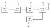
여기서 상기 CCTV(100)는 목적 대상을 촬영하는 카메라 모듈(10)과, 상기 카메라 모듈(10)로부터 촬영된 데이터를 압축하는 영상 인코더(20)와, 상기 영상 인코더(20)로부터 압축된 영상 데이터를 전송받아 헤더 데이터를 부여하는 패킷 먹서(30)와, 설정된 순서에 따라 영상데이터가 전송됨에 따라 이전 CCTV(100)로부터 전송받은 촬영 데이터 중 헤더 데이터를 제거하여 압축 영상 데이터를 추출하고 이를 패킷 먹서(30)로 전송함에 따라 패킷 먹서(30)에 의해 해당 영상 데이터와 이전 CCTV(100) 영상 데이터가 믹싱되도록 하는 패킷 디먹서(40)와, 상기 패킷 먹서(30)로부터 믹싱된 영상데이터를 설정 순서에 따라 이후의 CCTV(100)에 전송하고 이전 CCTV(100)로부터 믹싱된 영상데이터를 전송받아 이를 패킷 디먹서(40)로 전송하는 무선랜모듈(50)로 이루어진다.Here, the
이러한 본 발명의 가장 큰 특징은 일반적으로 다수의 CCTV(100)가 설치된 관리시스템의 경우 각 CCTV(100)로부터 영상데이터를 관리 단말기로 전송받아 이를 출력하고 제어하게 되는데, 본 발명의 경우 근접 거리에 따라 이격된 거리에 따라 CCTV(100) 순서대로 설정 순서가 정해지고 이에 따라 가장 멀리 이격된 CCTV(100)의 영상데이터가 가장 근접한 후순위 CCTV(100)로 전송되어 후순위 CCTV(100)의 영상데이터와 믹싱, 다시 가장 근접한 후순위 CCTV로 재차 전송하는 것이다.The biggest feature of the present invention is that in the case of a management system installed with a plurality of CCTV (100) generally receives the image data from each CCTV (100) to the management terminal to output and control it, in the case of the present invention According to the spaced distance according to the setting order of CCTV (100) in order is set accordingly, the video data of the farthest spaced CCTV (100) is transmitted to the nearest subordinate priority CCTV (100) and the video data of the subordinated CCTV (100) Mix and send again to the nearest subordinate CCTV.
결국 모든 CCTV(100)의 영상데이터는 액세스 포인트(200)와 가장 근접한 CCTV(100)에서 하나의 믹싱 데이터로 추출되어 액세스 포인트(200)로 전송됨에 따라 무선랜을 이용한 CCTV 관리 시스템의 통신 거리 제한을 극복할 수 있게 되는 것이다.Eventually, the video data of all the CCTV (100) is extracted as one mixing data from the CCTV (100) closest to the
여기서 도 2를 통해 상기 CCTV(100)의 믹싱 과정을 살펴보면, 우선 엑세스 포인트(200)에서 가장 멀리 떨어져 있는 CCTV 1(100-1)의 카메라 모듈(10)에서 촬영되고 압축된 영상 데이터는 무선랜모듈(50)을 통해 CCTV 1(100-1)과 가장 근접 위치한 CCTV 2(100-2)로 전송된다.Here, looking at the mixing process of the CCTV (100) through FIG. 2, first, the image data captured and compressed by the
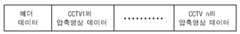
이때 CCTV 1(100-1)에서 CCTV 2(100-2)로 전달되는 패킷 데이터는 도 3과 같 이 헤더 데이터와 CCTV 1(100-1)의 압축된 영상데이터로 구성된다. 헤더 데이터는 CCTV 2(100-2)의 주소를 포함하고 있어 다른 CCTV 및 엑세스 포인트(200)는 데이터를 수신하지 않고 오직 CCTV 2(100-2)만 CCTV 1(100-1)의 패킷데이터를 받을 수 있도록 한다.At this time, the packet data transmitted from CCTV 1 (100-1) to CCTV 2 (100-2) is composed of the header data and the compressed image data of CCTV 1 (100-1) as shown in FIG. The header data contains the address of CCTV 2 (100-2), so other CCTVs and
CCTV 2(100-2)는 자신의 카메라 모듈(10)에서 촬영되고 압축된 영상 데이터와 CCTV 1(100-1)에서 받은 압축된 영상 데이터를 합쳐서 설정 순서에 따라 가장 근접 위치하는 또 다른 CCTV 3(100-3)으로 무선랜모듈(50)을 통하여 도 4와 같은 패킷을 전송한다. 이때, 헤더 데이터는 CCTV 3(100-3)의 주소를 포함하여 다른 CCTV 및 엑세스 포인트(200)는 데이터를 받지 않고 CCTV 3(100-3)만 데이터를 받을 수 있도록 한다.CCTV 2 (100-2) is another CCTV 3 that is located closest to the set sequence by combining the compressed image data taken by the
이렇게 하여 엑세스 포인트(200)에서 가장 가까이 있는 CCTV n(100-n)는 자기가 압축한 영상 데이터와 바로 이전 순위의 CCTV n-1(100-(n-1))에서 받은 압축된 영상 데이터를 합쳐서 무선랜모듈(50)을 통하여 최종적으로 엑세스 포인트(200)로 도 5와 같은 패킷을 전송하게 되는 것이다.In this way, the CCTV n (100-n) closest to the
엑세스 포인트(200)의 수신부는 CCTV n(100-n)으로부터 패킷 데이터를 수신하고, 영상 디코더(400)는 CCTV 1(100-1)부터 CCTV n(100-n)의 압축된 영상데이터를 디코딩하여 디스플레이 장치(500)로 전달한다.The receiver of the
도 6은 본 발명에서의 데이터 송수신 거리를 나타낸다. 일반적으로 무선랜은 10m~100m 까지 데이터를 전송할 수 있기 때문에 일반적인 무선랜을 사용하는 CCTV(100)는 이 범위를 벋어날 수 없다. 하지만 본 발명에서는 동영상 데이터의 품 질 허용 범위 내에서 여러 대의 CCTV(100)를 설치하여 데이터 전송 거리를 늘일 수 있다.6 shows data transmission / reception distances in the present invention. In general, since the wireless LAN can transmit data from 10m to 100m, the
예를 들어 각각의 CCTV(100)가 동영상 데이터를 QCIF (176*144), 15fps로 압축하여 384kbps로 데이터를 전송한다고 가정하면, 54Mbps (IEEE802.11g) 규격의 무선랜으로 전송할 수 있는 데이터의 양은 약 140대 (54Mbps/384kbps)의 CCTV 데이터가 된다. 따라서 각 CCTV(100)가 전송할 수 있는 데이터의 반경이 10m 라고 하면 약 1.4km 까지 데이터 전송 거리를 확장할 수 있는 것이다..For example, assuming that each
상기 각 CCTV(100)의 구성을 살펴보면 도 7과 같이 카메라 모듈(10), 영상 인코더(20), 패킷 먹서(30), 패킷 디먹서(40) 및 무선랜모듈(50)로 구성된다. 카메라 모듈(10)에서 촬영된 영상 데이터는 많은 양의 영상 데이터를 전송하기 위하여 영상 인코더(20)에서 압축되고, 압축된 데이터는 패킷 먹서(30, Muxer)에서 헤더 데이터와 조합되어 도 3과 같은 패킷으로 만들어진다.Looking at the configuration of each CCTV (100) as shown in Figure 7 is composed of a
이때 헤더 데이터는 전술하였듯이 CCTV 2(100-2)의 주소를 포함하고 있어 다른 CCTV 및 엑세스 포인트(200)는 데이터를 받지 않고 CCTV 2(100-2)만 패킷을 받을 수 있도록 구성됨은 물론이다. 도 3의 패킷은 무선랜모듈(50)을 통하여 CCTV 2(100-2)로 전송된다.At this time, the header data includes the address of CCTV 2 (100-2) as described above, so that other CCTV and
물론 최초의 CCTV 1(100-1)의 경우 패킷 디먹서(40)가 구동되지 않음은 물론이며, CCTV 2(100-2) 내지 CCTV n(100-n)의 경우에는 이전 CCTV(100)로부터 전송받은 패킷을 패킷 디먹서(40)에서 압축된 영상 데이터만 추출되어 패킷 먹서(30)로 전달한다.Of course, in the case of the first CCTV 1 (100-1), the
이에 따라 패킷 먹서(30)는 영상 인코더(20)에서 전달된 압축된 영상 데이터와 헤더 데이터 및 이전 CCTV(100)의 추출된 압축 영상 데이터를 믹싱하여 도 4와 같은 패킷을 구성한다.Accordingly, the
한편 CCTV n(100-n)의 경우 CCTV n-1(100-(n-1))으로부터 수신된 압축된 영상 데이터를 조합하여 도 5와 같은 패킷을 구성하며 헤더 데이터는 엑세스 포인트(200)의 주소를 포함하고 있어 엑세스 포인트(200)만 패킷을 받을 수 있도록 한다.Meanwhile, in the case of CCTV n (100-n), the compressed video data received from CCTV n-1 (100- (n-1)) is combined to form a packet as shown in FIG. 5, and the header data of the
아울러 상기 CCTV n(100-n)으로부터 받은 패킷 데이터를 패킷 디먹서(300)로 전달한다. 여기서 패킷 디먹서(300)는 전술한 CCTV(100) 내의 패킷 디먹서(40)와 동일한 기능을 수행함은 물론이다.In addition, the packet data received from the CCTV n (100-n) is transmitted to the
이에 따라 패킷 디먹서(300)가 CCTV n(100-n)의 패킷데이터에서 헤더 데이터를 제거한 추출 압축 영상데이터를 영상 디코더(400)로 전달한다. 영상 디코더(400)는 CCTV 1(100-1)부터 CCTV n(100-n)까지의 압축된 영상데이터를 디코딩하여 디스플레이 수단으로 전송하고 모니터 또는 터치스크린과 같은 디스플레이 수단은 이를 출력함으로써 관리 작업자는 촬영 대상 범위를 관찰할 수 있게 된다.Accordingly, the
이와 같이 본 발명은 도면에 도시된 실시예들로 설명되었으나, 이는 예시적인 것에 불과하며, 본 기술 분야의 통상의 지식을 가진 자라면 이로부터 다양한 변형 및 균등한 타 실시예가 가능하다는 점을 이해할 것이다.As described above, the present invention has been described in the embodiments shown in the drawings, but this is merely exemplary, and it will be understood by those skilled in the art that various modifications and equivalent other embodiments are possible. .
따라서, 본 발명의 진정한 기술적 보호범위는 첨부된 특허청구범위의 기술적 사상에 의해 정해져야 할 것이다.Therefore, the true technical protection scope of the present invention will be defined by the technical spirit of the appended claims.
도 1은 종래 유선형태의 CCTV 관리 시스템의 구성도.1 is a block diagram of a conventional CCTV management system of the wired form.
도 2는 본 발명에 따른 CCTV 관리 시스템의 개략적인 구성도.2 is a schematic configuration diagram of a CCTV management system according to the present invention.
도 3 내지 도 5는 CCTV 1, CCTV 2, CCTL n의 패킷 구성을 나타내는 도면.3 to 5 are diagrams showing the packet configuration of
도 6은 본 발명에 따른 CCTV 관리 시스템의 촬영 대상 구간을 나타내는 도면.6 is a view showing a shooting target section of the CCTV management system according to the present invention.
도 7은 본 발명에 따른 CCTV의 내부 구성을 나타내는 블럭도.Figure 7 is a block diagram showing the internal configuration of the CCTV according to the present invention.
<도면의 주요부분에 대한 부호 설명><Description of Signs of Major Parts of Drawings>
10 : 카메라 모듈20 : 영상 인코더10: camera module 20: video encoder
30 : 패킷 먹서40, 300 : 패킷 디먹서30:
50 : 무선랜모듈100 : CCTV50: wireless LAN module 100: CCTV
200 : 액서스 포인트400 : 영상 디코더200: access point 400: video decoder
500 : 디스플레이 수단500: display means
Claims (3)
Translated fromKoreanPriority Applications (2)
| Application Number | Priority Date | Filing Date | Title |
|---|---|---|---|
| KR1020080061212AKR101000531B1 (en) | 2008-06-26 | 2008-06-26 | CC management system using wireless LAN that increases data transmission range |
| US12/492,719US20090322876A1 (en) | 2008-06-26 | 2009-06-26 | Cctv management system supporting extended data transmission coverage through wireless lan |
Applications Claiming Priority (1)
| Application Number | Priority Date | Filing Date | Title |
|---|---|---|---|
| KR1020080061212AKR101000531B1 (en) | 2008-06-26 | 2008-06-26 | CC management system using wireless LAN that increases data transmission range |
Publications (2)
| Publication Number | Publication Date |
|---|---|
| KR20100001347A KR20100001347A (en) | 2010-01-06 |
| KR101000531B1true KR101000531B1 (en) | 2010-12-14 |
Family
ID=41446893
Family Applications (1)
| Application Number | Title | Priority Date | Filing Date |
|---|---|---|---|
| KR1020080061212AExpired - Fee RelatedKR101000531B1 (en) | 2008-06-26 | 2008-06-26 | CC management system using wireless LAN that increases data transmission range |
Country Status (2)
| Country | Link |
|---|---|
| US (1) | US20090322876A1 (en) |
| KR (1) | KR101000531B1 (en) |
Families Citing this family (54)
| Publication number | Priority date | Publication date | Assignee | Title |
|---|---|---|---|---|
| US11792538B2 (en) | 2008-05-20 | 2023-10-17 | Adeia Imaging Llc | Capturing and processing of images including occlusions focused on an image sensor by a lens stack array |
| US8866920B2 (en) | 2008-05-20 | 2014-10-21 | Pelican Imaging Corporation | Capturing and processing of images using monolithic camera array with heterogeneous imagers |
| DK3876510T3 (en) | 2008-05-20 | 2024-11-11 | Adeia Imaging Llc | CAPTURE AND PROCESSING OF IMAGES USING MONOLITHIC CAMERA ARRAY WITH HETEROGENEOUS IMAGES |
| EP2502115A4 (en) | 2009-11-20 | 2013-11-06 | Pelican Imaging Corp | CAPTURE AND IMAGE PROCESSING USING A MONOLITHIC CAMERAS NETWORK EQUIPPED WITH HETEROGENEOUS IMAGERS |
| KR101116962B1 (en)* | 2010-02-01 | 2012-03-13 | 한남대학교 산학협력단 | image data transferring device |
| US8928793B2 (en)* | 2010-05-12 | 2015-01-06 | Pelican Imaging Corporation | Imager array interfaces |
| US8878950B2 (en) | 2010-12-14 | 2014-11-04 | Pelican Imaging Corporation | Systems and methods for synthesizing high resolution images using super-resolution processes |
| EP2708019B1 (en) | 2011-05-11 | 2019-10-16 | FotoNation Limited | Systems and methods for transmitting and receiving array camera image data |
| US20130070060A1 (en) | 2011-09-19 | 2013-03-21 | Pelican Imaging Corporation | Systems and methods for determining depth from multiple views of a scene that include aliasing using hypothesized fusion |
| CN104081414B (en) | 2011-09-28 | 2017-08-01 | Fotonation开曼有限公司 | Systems and methods for encoding and decoding light field image files |
| EP2817955B1 (en) | 2012-02-21 | 2018-04-11 | FotoNation Cayman Limited | Systems and methods for the manipulation of captured light field image data |
| US9210392B2 (en) | 2012-05-01 | 2015-12-08 | Pelican Imaging Coporation | Camera modules patterned with pi filter groups |
| JP2015534734A (en) | 2012-06-28 | 2015-12-03 | ペリカン イメージング コーポレイション | System and method for detecting defective camera arrays, optical arrays, and sensors |
| US20140002674A1 (en) | 2012-06-30 | 2014-01-02 | Pelican Imaging Corporation | Systems and Methods for Manufacturing Camera Modules Using Active Alignment of Lens Stack Arrays and Sensors |
| PL4296963T3 (en) | 2012-08-21 | 2025-04-28 | Adeia Imaging Llc | Method for depth detection in images captured using array cameras |
| WO2014032020A2 (en) | 2012-08-23 | 2014-02-27 | Pelican Imaging Corporation | Feature based high resolution motion estimation from low resolution images captured using an array source |
| EP4307659A1 (en) | 2012-09-28 | 2024-01-17 | Adeia Imaging LLC | Generating images from light fields utilizing virtual viewpoints |
| WO2014078443A1 (en) | 2012-11-13 | 2014-05-22 | Pelican Imaging Corporation | Systems and methods for array camera focal plane control |
| US9462164B2 (en) | 2013-02-21 | 2016-10-04 | Pelican Imaging Corporation | Systems and methods for generating compressed light field representation data using captured light fields, array geometry, and parallax information |
| US9374512B2 (en) | 2013-02-24 | 2016-06-21 | Pelican Imaging Corporation | Thin form factor computational array cameras and modular array cameras |
| US9774789B2 (en) | 2013-03-08 | 2017-09-26 | Fotonation Cayman Limited | Systems and methods for high dynamic range imaging using array cameras |
| US8866912B2 (en) | 2013-03-10 | 2014-10-21 | Pelican Imaging Corporation | System and methods for calibration of an array camera using a single captured image |
| US9124831B2 (en) | 2013-03-13 | 2015-09-01 | Pelican Imaging Corporation | System and methods for calibration of an array camera |
| US9888194B2 (en) | 2013-03-13 | 2018-02-06 | Fotonation Cayman Limited | Array camera architecture implementing quantum film image sensors |
| WO2014165244A1 (en) | 2013-03-13 | 2014-10-09 | Pelican Imaging Corporation | Systems and methods for synthesizing images from image data captured by an array camera using restricted depth of field depth maps in which depth estimation precision varies |
| WO2014153098A1 (en) | 2013-03-14 | 2014-09-25 | Pelican Imaging Corporation | Photmetric normalization in array cameras |
| US9578259B2 (en) | 2013-03-14 | 2017-02-21 | Fotonation Cayman Limited | Systems and methods for reducing motion blur in images or video in ultra low light with array cameras |
| US9497429B2 (en) | 2013-03-15 | 2016-11-15 | Pelican Imaging Corporation | Extended color processing on pelican array cameras |
| US10122993B2 (en) | 2013-03-15 | 2018-11-06 | Fotonation Limited | Autofocus system for a conventional camera that uses depth information from an array camera |
| US9445003B1 (en) | 2013-03-15 | 2016-09-13 | Pelican Imaging Corporation | Systems and methods for synthesizing high resolution images using image deconvolution based on motion and depth information |
| US9438888B2 (en) | 2013-03-15 | 2016-09-06 | Pelican Imaging Corporation | Systems and methods for stereo imaging with camera arrays |
| US9898856B2 (en) | 2013-09-27 | 2018-02-20 | Fotonation Cayman Limited | Systems and methods for depth-assisted perspective distortion correction |
| US9264592B2 (en) | 2013-11-07 | 2016-02-16 | Pelican Imaging Corporation | Array camera modules incorporating independently aligned lens stacks |
| US10119808B2 (en) | 2013-11-18 | 2018-11-06 | Fotonation Limited | Systems and methods for estimating depth from projected texture using camera arrays |
| WO2015081279A1 (en) | 2013-11-26 | 2015-06-04 | Pelican Imaging Corporation | Array camera configurations incorporating multiple constituent array cameras |
| US10089740B2 (en) | 2014-03-07 | 2018-10-02 | Fotonation Limited | System and methods for depth regularization and semiautomatic interactive matting using RGB-D images |
| JP2017531976A (en) | 2014-09-29 | 2017-10-26 | フォトネイション ケイマン リミテッド | System and method for dynamically calibrating an array camera |
| US10482618B2 (en) | 2017-08-21 | 2019-11-19 | Fotonation Limited | Systems and methods for hybrid depth regularization |
| US11270110B2 (en) | 2019-09-17 | 2022-03-08 | Boston Polarimetrics, Inc. | Systems and methods for surface modeling using polarization cues |
| WO2021071992A1 (en) | 2019-10-07 | 2021-04-15 | Boston Polarimetrics, Inc. | Systems and methods for augmentation of sensor systems and imaging systems with polarization |
| DE112020005932T5 (en) | 2019-11-30 | 2023-01-05 | Boston Polarimetrics, Inc. | SYSTEMS AND METHODS FOR SEGMENTATION OF TRANSPARENT OBJECTS USING POLARIZATION CHARACTERISTICS |
| EP4081933A4 (en) | 2020-01-29 | 2024-03-20 | Intrinsic Innovation LLC | Systems and methods for characterizing object pose detection and measurement systems |
| US11797863B2 (en) | 2020-01-30 | 2023-10-24 | Intrinsic Innovation Llc | Systems and methods for synthesizing data for training statistical models on different imaging modalities including polarized images |
| US11953700B2 (en) | 2020-05-27 | 2024-04-09 | Intrinsic Innovation Llc | Multi-aperture polarization optical systems using beam splitters |
| US12069227B2 (en) | 2021-03-10 | 2024-08-20 | Intrinsic Innovation Llc | Multi-modal and multi-spectral stereo camera arrays |
| US12020455B2 (en) | 2021-03-10 | 2024-06-25 | Intrinsic Innovation Llc | Systems and methods for high dynamic range image reconstruction |
| US11290658B1 (en) | 2021-04-15 | 2022-03-29 | Boston Polarimetrics, Inc. | Systems and methods for camera exposure control |
| US11954886B2 (en) | 2021-04-15 | 2024-04-09 | Intrinsic Innovation Llc | Systems and methods for six-degree of freedom pose estimation of deformable objects |
| US12067746B2 (en) | 2021-05-07 | 2024-08-20 | Intrinsic Innovation Llc | Systems and methods for using computer vision to pick up small objects |
| US12175741B2 (en) | 2021-06-22 | 2024-12-24 | Intrinsic Innovation Llc | Systems and methods for a vision guided end effector |
| US12340538B2 (en) | 2021-06-25 | 2025-06-24 | Intrinsic Innovation Llc | Systems and methods for generating and using visual datasets for training computer vision models |
| US12172310B2 (en) | 2021-06-29 | 2024-12-24 | Intrinsic Innovation Llc | Systems and methods for picking objects using 3-D geometry and segmentation |
| US11689813B2 (en) | 2021-07-01 | 2023-06-27 | Intrinsic Innovation Llc | Systems and methods for high dynamic range imaging using crossed polarizers |
| US12293535B2 (en) | 2021-08-03 | 2025-05-06 | Intrinsic Innovation Llc | Systems and methods for training pose estimators in computer vision |
Family Cites Families (6)
| Publication number | Priority date | Publication date | Assignee | Title |
|---|---|---|---|---|
| US6356294B1 (en)* | 1998-08-11 | 2002-03-12 | 8×8, Inc. | Multi-point communication arrangement and method |
| US6970183B1 (en)* | 2000-06-14 | 2005-11-29 | E-Watch, Inc. | Multimedia surveillance and monitoring system including network configuration |
| EP1102489A4 (en)* | 1999-05-24 | 2005-11-16 | Matsushita Electric Industrial Co Ltd | DEVICE FOR SWITCHING PICTURES AND DEVICES FOR PUBLISHING IMAGES |
| US6768508B1 (en)* | 2001-04-23 | 2004-07-27 | Sensormatic Electronics Corporation | Video node for frame synchronized multi-node video camera array |
| US20060098729A1 (en)* | 2004-11-09 | 2006-05-11 | Lien-Chieh Shen | Smart image processing CCTV camera device and method for operating same |
| US7603087B1 (en)* | 2005-08-12 | 2009-10-13 | Smartvue Corporation | Wireless video surveillance jamming and interface prevention |
- 2008
- 2008-06-26KRKR1020080061212Apatent/KR101000531B1/ennot_activeExpired - Fee Related
- 2009
- 2009-06-26USUS12/492,719patent/US20090322876A1/ennot_activeAbandoned
Also Published As
| Publication number | Publication date |
|---|---|
| US20090322876A1 (en) | 2009-12-31 |
| KR20100001347A (en) | 2010-01-06 |
Similar Documents
| Publication | Publication Date | Title |
|---|---|---|
| KR101000531B1 (en) | CC management system using wireless LAN that increases data transmission range | |
| US7885681B2 (en) | Method of using mobile communications devices for monitoring purposes and a system for implementation thereof | |
| US20090051769A1 (en) | Method and system for remote monitoring and surveillance | |
| CN100515010C (en) | Image transmission apparatus and image transmission method | |
| CN103516382B (en) | Use the security system and method for wireless adapter and PoE camera | |
| US20210061466A1 (en) | Monitoring events employing a drone having a camera controlled via an application | |
| US20090016622A1 (en) | Image transmitting apparatus, image transmitting method, receiving apparatus, and image transmitting system | |
| TW200620902A (en) | Viewing system | |
| US7821550B2 (en) | Remote image-pickup system, camera device, and card substrate | |
| US20150015719A1 (en) | Interface device for video cameras | |
| US20090195653A1 (en) | Method And System For Transmitting Video Images Using Video Cameras Embedded In Signal/Street Lights | |
| KR101682982B1 (en) | An IP Transmitting System For CCTV Video Signal | |
| US20060284977A1 (en) | System and method for secure digital video | |
| KR20110124138A (en) | Controls, camera systems and programs | |
| WO2011142513A1 (en) | Binary cdma image-transceiving system directly connected to an image capture device | |
| CN201025724Y (en) | Signal receiving and transmission device | |
| US9247287B2 (en) | Communal television receiving system and method thereof | |
| KR101253133B1 (en) | The monitoring system used to the cloud service, and its service method | |
| KR101113801B1 (en) | High magnification and high distinctness observation apparatus | |
| KR100764088B1 (en) | Surveillance video transmitter | |
| KR101145408B1 (en) | Realtime Multi-channel Video Security Mobile System using Binary CDMA | |
| KR20140115057A (en) | Closed-circuit television system for transferring compressed, high-resolution digital video signal through coaxial cable | |
| CN102625088A (en) | Point-to-point and node-to-surface video monitoring system | |
| KR101302401B1 (en) | Apparatus and method for distributed process of image source | |
| KR20190069658A (en) | System and method for service security |
Legal Events
| Date | Code | Title | Description |
|---|---|---|---|
| A201 | Request for examination | ||
| PA0109 | Patent application | St.27 status event code:A-0-1-A10-A12-nap-PA0109 | |
| PA0201 | Request for examination | St.27 status event code:A-1-2-D10-D11-exm-PA0201 | |
| P11-X000 | Amendment of application requested | St.27 status event code:A-2-2-P10-P11-nap-X000 | |
| P13-X000 | Application amended | St.27 status event code:A-2-2-P10-P13-nap-X000 | |
| P11-X000 | Amendment of application requested | St.27 status event code:A-2-2-P10-P11-nap-X000 | |
| P13-X000 | Application amended | St.27 status event code:A-2-2-P10-P13-nap-X000 | |
| E902 | Notification of reason for refusal | ||
| PE0902 | Notice of grounds for rejection | St.27 status event code:A-1-2-D10-D21-exm-PE0902 | |
| PG1501 | Laying open of application | St.27 status event code:A-1-1-Q10-Q12-nap-PG1501 | |
| T11-X000 | Administrative time limit extension requested | St.27 status event code:U-3-3-T10-T11-oth-X000 | |
| P11-X000 | Amendment of application requested | St.27 status event code:A-2-2-P10-P11-nap-X000 | |
| P13-X000 | Application amended | St.27 status event code:A-2-2-P10-P13-nap-X000 | |
| T11-X000 | Administrative time limit extension requested | St.27 status event code:U-3-3-T10-T11-oth-X000 | |
| T11-X000 | Administrative time limit extension requested | St.27 status event code:U-3-3-T10-T11-oth-X000 | |
| T11-X000 | Administrative time limit extension requested | St.27 status event code:U-3-3-T10-T11-oth-X000 | |
| E13-X000 | Pre-grant limitation requested | St.27 status event code:A-2-3-E10-E13-lim-X000 | |
| P11-X000 | Amendment of application requested | St.27 status event code:A-2-2-P10-P11-nap-X000 | |
| P13-X000 | Application amended | St.27 status event code:A-2-2-P10-P13-nap-X000 | |
| R18-X000 | Changes to party contact information recorded | St.27 status event code:A-3-3-R10-R18-oth-X000 | |
| E701 | Decision to grant or registration of patent right | ||
| PE0701 | Decision of registration | St.27 status event code:A-1-2-D10-D22-exm-PE0701 | |
| GRNT | Written decision to grant | ||
| PR0701 | Registration of establishment | St.27 status event code:A-2-4-F10-F11-exm-PR0701 | |
| PR1002 | Payment of registration fee | St.27 status event code:A-2-2-U10-U11-oth-PR1002 Fee payment year number:1 | |
| PG1601 | Publication of registration | St.27 status event code:A-4-4-Q10-Q13-nap-PG1601 | |
| FPAY | Annual fee payment | Payment date:20130801 Year of fee payment:4 | |
| PR1001 | Payment of annual fee | St.27 status event code:A-4-4-U10-U11-oth-PR1001 Fee payment year number:4 | |
| FPAY | Annual fee payment | Payment date:20141208 Year of fee payment:5 | |
| PR1001 | Payment of annual fee | St.27 status event code:A-4-4-U10-U11-oth-PR1001 Fee payment year number:5 | |
| FPAY | Annual fee payment | Payment date:20151204 Year of fee payment:6 | |
| PR1001 | Payment of annual fee | St.27 status event code:A-4-4-U10-U11-oth-PR1001 Fee payment year number:6 | |
| FPAY | Annual fee payment | Payment date:20161206 Year of fee payment:7 | |
| PR1001 | Payment of annual fee | St.27 status event code:A-4-4-U10-U11-oth-PR1001 Fee payment year number:7 | |
| FPAY | Annual fee payment | Payment date:20171206 Year of fee payment:8 | |
| PR1001 | Payment of annual fee | St.27 status event code:A-4-4-U10-U11-oth-PR1001 Fee payment year number:8 | |
| PR1001 | Payment of annual fee | St.27 status event code:A-4-4-U10-U11-oth-PR1001 Fee payment year number:9 | |
| FPAY | Annual fee payment | Payment date:20191203 Year of fee payment:10 | |
| PR1001 | Payment of annual fee | St.27 status event code:A-4-4-U10-U11-oth-PR1001 Fee payment year number:10 | |
| PC1903 | Unpaid annual fee | St.27 status event code:A-4-4-U10-U13-oth-PC1903 Not in force date:20201207 Payment event data comment text:Termination Category : DEFAULT_OF_REGISTRATION_FEE | |
| PC1903 | Unpaid annual fee | St.27 status event code:N-4-6-H10-H13-oth-PC1903 Ip right cessation event data comment text:Termination Category : DEFAULT_OF_REGISTRATION_FEE Not in force date:20201207 |