KR101000175B1 - Printer unit with pagewidth printhead - Google Patents
Printer unit with pagewidth printheadDownload PDFInfo
- Publication number
- KR101000175B1 KR101000175B1KR1020087001860AKR20087001860AKR101000175B1KR 101000175 B1KR101000175 B1KR 101000175B1KR 1020087001860 AKR1020087001860 AKR 1020087001860AKR 20087001860 AKR20087001860 AKR 20087001860AKR 101000175 B1KR101000175 B1KR 101000175B1
- Authority
- KR
- South Korea
- Prior art keywords
- media
- printhead
- printer unit
- printing
- Prior art date
- Legal status (The legal status is an assumption and is not a legal conclusion. Google has not performed a legal analysis and makes no representation as to the accuracy of the status listed.)
- Expired - Fee Related
Links
Images


Classifications
- B—PERFORMING OPERATIONS; TRANSPORTING
- B41—PRINTING; LINING MACHINES; TYPEWRITERS; STAMPS
- B41J—TYPEWRITERS; SELECTIVE PRINTING MECHANISMS, i.e. MECHANISMS PRINTING OTHERWISE THAN FROM A FORME; CORRECTION OF TYPOGRAPHICAL ERRORS
- B41J2/00—Typewriters or selective printing mechanisms characterised by the printing or marking process for which they are designed
- B41J2/005—Typewriters or selective printing mechanisms characterised by the printing or marking process for which they are designed characterised by bringing liquid or particles selectively into contact with a printing material
- B41J2/01—Ink jet
- B41J2/17—Ink jet characterised by ink handling
- B41J2/175—Ink supply systems ; Circuit parts therefor
- B—PERFORMING OPERATIONS; TRANSPORTING
- B41—PRINTING; LINING MACHINES; TYPEWRITERS; STAMPS
- B41J—TYPEWRITERS; SELECTIVE PRINTING MECHANISMS, i.e. MECHANISMS PRINTING OTHERWISE THAN FROM A FORME; CORRECTION OF TYPOGRAPHICAL ERRORS
- B41J25/00—Actions or mechanisms not otherwise provided for
- B41J25/34—Bodily-changeable print heads or carriages
- B—PERFORMING OPERATIONS; TRANSPORTING
- B41—PRINTING; LINING MACHINES; TYPEWRITERS; STAMPS
- B41J—TYPEWRITERS; SELECTIVE PRINTING MECHANISMS, i.e. MECHANISMS PRINTING OTHERWISE THAN FROM A FORME; CORRECTION OF TYPOGRAPHICAL ERRORS
- B41J2/00—Typewriters or selective printing mechanisms characterised by the printing or marking process for which they are designed
- B41J2/005—Typewriters or selective printing mechanisms characterised by the printing or marking process for which they are designed characterised by bringing liquid or particles selectively into contact with a printing material
- B41J2/01—Ink jet
- B41J2/015—Ink jet characterised by the jet generation process
- B41J2/04—Ink jet characterised by the jet generation process generating single droplets or particles on demand
- B41J2/045—Ink jet characterised by the jet generation process generating single droplets or particles on demand by pressure, e.g. electromechanical transducers
- B41J2/04501—Control methods or devices therefor, e.g. driver circuits, control circuits
- B41J2/04541—Specific driving circuit
- B—PERFORMING OPERATIONS; TRANSPORTING
- B41—PRINTING; LINING MACHINES; TYPEWRITERS; STAMPS
- B41J—TYPEWRITERS; SELECTIVE PRINTING MECHANISMS, i.e. MECHANISMS PRINTING OTHERWISE THAN FROM A FORME; CORRECTION OF TYPOGRAPHICAL ERRORS
- B41J2/00—Typewriters or selective printing mechanisms characterised by the printing or marking process for which they are designed
- B41J2/005—Typewriters or selective printing mechanisms characterised by the printing or marking process for which they are designed characterised by bringing liquid or particles selectively into contact with a printing material
- B41J2/01—Ink jet
- B41J2/015—Ink jet characterised by the jet generation process
- B41J2/04—Ink jet characterised by the jet generation process generating single droplets or particles on demand
- B41J2/045—Ink jet characterised by the jet generation process generating single droplets or particles on demand by pressure, e.g. electromechanical transducers
- B41J2/04501—Control methods or devices therefor, e.g. driver circuits, control circuits
- B41J2/04543—Block driving
- B—PERFORMING OPERATIONS; TRANSPORTING
- B41—PRINTING; LINING MACHINES; TYPEWRITERS; STAMPS
- B41J—TYPEWRITERS; SELECTIVE PRINTING MECHANISMS, i.e. MECHANISMS PRINTING OTHERWISE THAN FROM A FORME; CORRECTION OF TYPOGRAPHICAL ERRORS
- B41J2/00—Typewriters or selective printing mechanisms characterised by the printing or marking process for which they are designed
- B41J2/005—Typewriters or selective printing mechanisms characterised by the printing or marking process for which they are designed characterised by bringing liquid or particles selectively into contact with a printing material
- B41J2/01—Ink jet
- B41J2/015—Ink jet characterised by the jet generation process
- B41J2/04—Ink jet characterised by the jet generation process generating single droplets or particles on demand
- B41J2/045—Ink jet characterised by the jet generation process generating single droplets or particles on demand by pressure, e.g. electromechanical transducers
- B41J2/04501—Control methods or devices therefor, e.g. driver circuits, control circuits
- B41J2/0458—Control methods or devices therefor, e.g. driver circuits, control circuits controlling heads based on heating elements forming bubbles
- B—PERFORMING OPERATIONS; TRANSPORTING
- B41—PRINTING; LINING MACHINES; TYPEWRITERS; STAMPS
- B41J—TYPEWRITERS; SELECTIVE PRINTING MECHANISMS, i.e. MECHANISMS PRINTING OTHERWISE THAN FROM A FORME; CORRECTION OF TYPOGRAPHICAL ERRORS
- B41J2/00—Typewriters or selective printing mechanisms characterised by the printing or marking process for which they are designed
- B41J2/005—Typewriters or selective printing mechanisms characterised by the printing or marking process for which they are designed characterised by bringing liquid or particles selectively into contact with a printing material
- B41J2/01—Ink jet
- B41J2/015—Ink jet characterised by the jet generation process
- B41J2/04—Ink jet characterised by the jet generation process generating single droplets or particles on demand
- B41J2/045—Ink jet characterised by the jet generation process generating single droplets or particles on demand by pressure, e.g. electromechanical transducers
- B41J2/04501—Control methods or devices therefor, e.g. driver circuits, control circuits
- B41J2/04585—Control methods or devices therefor, e.g. driver circuits, control circuits controlling heads based on thermal bent actuators
- B—PERFORMING OPERATIONS; TRANSPORTING
- B41—PRINTING; LINING MACHINES; TYPEWRITERS; STAMPS
- B41J—TYPEWRITERS; SELECTIVE PRINTING MECHANISMS, i.e. MECHANISMS PRINTING OTHERWISE THAN FROM A FORME; CORRECTION OF TYPOGRAPHICAL ERRORS
- B41J2/00—Typewriters or selective printing mechanisms characterised by the printing or marking process for which they are designed
- B41J2/005—Typewriters or selective printing mechanisms characterised by the printing or marking process for which they are designed characterised by bringing liquid or particles selectively into contact with a printing material
- B41J2/01—Ink jet
- B41J2/015—Ink jet characterised by the jet generation process
- B41J2/04—Ink jet characterised by the jet generation process generating single droplets or particles on demand
- B41J2/045—Ink jet characterised by the jet generation process generating single droplets or particles on demand by pressure, e.g. electromechanical transducers
- B41J2/04501—Control methods or devices therefor, e.g. driver circuits, control circuits
- B41J2/04591—Width of the driving signal being adjusted
- B—PERFORMING OPERATIONS; TRANSPORTING
- B41—PRINTING; LINING MACHINES; TYPEWRITERS; STAMPS
- B41J—TYPEWRITERS; SELECTIVE PRINTING MECHANISMS, i.e. MECHANISMS PRINTING OTHERWISE THAN FROM A FORME; CORRECTION OF TYPOGRAPHICAL ERRORS
- B41J2/00—Typewriters or selective printing mechanisms characterised by the printing or marking process for which they are designed
- B41J2/005—Typewriters or selective printing mechanisms characterised by the printing or marking process for which they are designed characterised by bringing liquid or particles selectively into contact with a printing material
- B41J2/01—Ink jet
- B41J2/135—Nozzles
- B41J2/14—Structure thereof only for on-demand ink jet heads
- B41J2/14016—Structure of bubble jet print heads
- B—PERFORMING OPERATIONS; TRANSPORTING
- B41—PRINTING; LINING MACHINES; TYPEWRITERS; STAMPS
- B41J—TYPEWRITERS; SELECTIVE PRINTING MECHANISMS, i.e. MECHANISMS PRINTING OTHERWISE THAN FROM A FORME; CORRECTION OF TYPOGRAPHICAL ERRORS
- B41J2/00—Typewriters or selective printing mechanisms characterised by the printing or marking process for which they are designed
- B41J2/005—Typewriters or selective printing mechanisms characterised by the printing or marking process for which they are designed characterised by bringing liquid or particles selectively into contact with a printing material
- B41J2/01—Ink jet
- B41J2/135—Nozzles
- B41J2/14—Structure thereof only for on-demand ink jet heads
- B41J2/14427—Structure of ink jet print heads with thermal bend detached actuators
- B—PERFORMING OPERATIONS; TRANSPORTING
- B41—PRINTING; LINING MACHINES; TYPEWRITERS; STAMPS
- B41J—TYPEWRITERS; SELECTIVE PRINTING MECHANISMS, i.e. MECHANISMS PRINTING OTHERWISE THAN FROM A FORME; CORRECTION OF TYPOGRAPHICAL ERRORS
- B41J2/00—Typewriters or selective printing mechanisms characterised by the printing or marking process for which they are designed
- B41J2/005—Typewriters or selective printing mechanisms characterised by the printing or marking process for which they are designed characterised by bringing liquid or particles selectively into contact with a printing material
- B41J2/01—Ink jet
- B41J2/135—Nozzles
- B41J2/145—Arrangement thereof
- B41J2/155—Arrangement thereof for line printing
- B—PERFORMING OPERATIONS; TRANSPORTING
- B41—PRINTING; LINING MACHINES; TYPEWRITERS; STAMPS
- B41J—TYPEWRITERS; SELECTIVE PRINTING MECHANISMS, i.e. MECHANISMS PRINTING OTHERWISE THAN FROM A FORME; CORRECTION OF TYPOGRAPHICAL ERRORS
- B41J2/00—Typewriters or selective printing mechanisms characterised by the printing or marking process for which they are designed
- B41J2/005—Typewriters or selective printing mechanisms characterised by the printing or marking process for which they are designed characterised by bringing liquid or particles selectively into contact with a printing material
- B41J2/01—Ink jet
- B41J2/135—Nozzles
- B41J2/16—Production of nozzles
- B41J2/1621—Manufacturing processes
- B41J2/1623—Manufacturing processes bonding and adhesion
- B—PERFORMING OPERATIONS; TRANSPORTING
- B41—PRINTING; LINING MACHINES; TYPEWRITERS; STAMPS
- B41J—TYPEWRITERS; SELECTIVE PRINTING MECHANISMS, i.e. MECHANISMS PRINTING OTHERWISE THAN FROM A FORME; CORRECTION OF TYPOGRAPHICAL ERRORS
- B41J2/00—Typewriters or selective printing mechanisms characterised by the printing or marking process for which they are designed
- B41J2/005—Typewriters or selective printing mechanisms characterised by the printing or marking process for which they are designed characterised by bringing liquid or particles selectively into contact with a printing material
- B41J2/01—Ink jet
- B41J2/135—Nozzles
- B41J2/16—Production of nozzles
- B41J2/1621—Manufacturing processes
- B41J2/1626—Manufacturing processes etching
- B41J2/1628—Manufacturing processes etching dry etching
- B—PERFORMING OPERATIONS; TRANSPORTING
- B41—PRINTING; LINING MACHINES; TYPEWRITERS; STAMPS
- B41J—TYPEWRITERS; SELECTIVE PRINTING MECHANISMS, i.e. MECHANISMS PRINTING OTHERWISE THAN FROM A FORME; CORRECTION OF TYPOGRAPHICAL ERRORS
- B41J2/00—Typewriters or selective printing mechanisms characterised by the printing or marking process for which they are designed
- B41J2/005—Typewriters or selective printing mechanisms characterised by the printing or marking process for which they are designed characterised by bringing liquid or particles selectively into contact with a printing material
- B41J2/01—Ink jet
- B41J2/135—Nozzles
- B41J2/16—Production of nozzles
- B41J2/1621—Manufacturing processes
- B41J2/1632—Manufacturing processes machining
- B41J2/1634—Manufacturing processes machining laser machining
- B—PERFORMING OPERATIONS; TRANSPORTING
- B41—PRINTING; LINING MACHINES; TYPEWRITERS; STAMPS
- B41J—TYPEWRITERS; SELECTIVE PRINTING MECHANISMS, i.e. MECHANISMS PRINTING OTHERWISE THAN FROM A FORME; CORRECTION OF TYPOGRAPHICAL ERRORS
- B41J2/00—Typewriters or selective printing mechanisms characterised by the printing or marking process for which they are designed
- B41J2/005—Typewriters or selective printing mechanisms characterised by the printing or marking process for which they are designed characterised by bringing liquid or particles selectively into contact with a printing material
- B41J2/01—Ink jet
- B41J2/135—Nozzles
- B41J2/16—Production of nozzles
- B41J2/1621—Manufacturing processes
- B41J2/1637—Manufacturing processes molding
- B—PERFORMING OPERATIONS; TRANSPORTING
- B41—PRINTING; LINING MACHINES; TYPEWRITERS; STAMPS
- B41J—TYPEWRITERS; SELECTIVE PRINTING MECHANISMS, i.e. MECHANISMS PRINTING OTHERWISE THAN FROM A FORME; CORRECTION OF TYPOGRAPHICAL ERRORS
- B41J2/00—Typewriters or selective printing mechanisms characterised by the printing or marking process for which they are designed
- B41J2/005—Typewriters or selective printing mechanisms characterised by the printing or marking process for which they are designed characterised by bringing liquid or particles selectively into contact with a printing material
- B41J2/01—Ink jet
- B41J2/135—Nozzles
- B41J2/16—Production of nozzles
- B41J2/1621—Manufacturing processes
- B41J2/164—Manufacturing processes thin film formation
- B41J2/1642—Manufacturing processes thin film formation thin film formation by CVD [chemical vapor deposition]
- B—PERFORMING OPERATIONS; TRANSPORTING
- B41—PRINTING; LINING MACHINES; TYPEWRITERS; STAMPS
- B41J—TYPEWRITERS; SELECTIVE PRINTING MECHANISMS, i.e. MECHANISMS PRINTING OTHERWISE THAN FROM A FORME; CORRECTION OF TYPOGRAPHICAL ERRORS
- B41J2/00—Typewriters or selective printing mechanisms characterised by the printing or marking process for which they are designed
- B41J2/005—Typewriters or selective printing mechanisms characterised by the printing or marking process for which they are designed characterised by bringing liquid or particles selectively into contact with a printing material
- B41J2/01—Ink jet
- B41J2/135—Nozzles
- B41J2/16—Production of nozzles
- B41J2/1648—Production of print heads with thermal bend detached actuators
- B—PERFORMING OPERATIONS; TRANSPORTING
- B41—PRINTING; LINING MACHINES; TYPEWRITERS; STAMPS
- B41J—TYPEWRITERS; SELECTIVE PRINTING MECHANISMS, i.e. MECHANISMS PRINTING OTHERWISE THAN FROM A FORME; CORRECTION OF TYPOGRAPHICAL ERRORS
- B41J2/00—Typewriters or selective printing mechanisms characterised by the printing or marking process for which they are designed
- B41J2/005—Typewriters or selective printing mechanisms characterised by the printing or marking process for which they are designed characterised by bringing liquid or particles selectively into contact with a printing material
- B41J2/01—Ink jet
- B41J2/135—Nozzles
- B41J2/165—Prevention or detection of nozzle clogging, e.g. cleaning, capping or moistening for nozzles
- B41J2/16517—Cleaning of print head nozzles
- B41J2/1652—Cleaning of print head nozzles by driving a fluid through the nozzles to the outside thereof, e.g. by applying pressure to the inside or vacuum at the outside of the print head
- B41J2/16526—Cleaning of print head nozzles by driving a fluid through the nozzles to the outside thereof, e.g. by applying pressure to the inside or vacuum at the outside of the print head by applying pressure only
- B—PERFORMING OPERATIONS; TRANSPORTING
- B41—PRINTING; LINING MACHINES; TYPEWRITERS; STAMPS
- B41J—TYPEWRITERS; SELECTIVE PRINTING MECHANISMS, i.e. MECHANISMS PRINTING OTHERWISE THAN FROM A FORME; CORRECTION OF TYPOGRAPHICAL ERRORS
- B41J2/00—Typewriters or selective printing mechanisms characterised by the printing or marking process for which they are designed
- B41J2/005—Typewriters or selective printing mechanisms characterised by the printing or marking process for which they are designed characterised by bringing liquid or particles selectively into contact with a printing material
- B41J2/01—Ink jet
- B41J2/135—Nozzles
- B41J2/165—Prevention or detection of nozzle clogging, e.g. cleaning, capping or moistening for nozzles
- B41J2/16517—Cleaning of print head nozzles
- B41J2/16535—Cleaning of print head nozzles using wiping constructions
- B—PERFORMING OPERATIONS; TRANSPORTING
- B41—PRINTING; LINING MACHINES; TYPEWRITERS; STAMPS
- B41J—TYPEWRITERS; SELECTIVE PRINTING MECHANISMS, i.e. MECHANISMS PRINTING OTHERWISE THAN FROM A FORME; CORRECTION OF TYPOGRAPHICAL ERRORS
- B41J2/00—Typewriters or selective printing mechanisms characterised by the printing or marking process for which they are designed
- B41J2/005—Typewriters or selective printing mechanisms characterised by the printing or marking process for which they are designed characterised by bringing liquid or particles selectively into contact with a printing material
- B41J2/01—Ink jet
- B41J2/135—Nozzles
- B41J2/165—Prevention or detection of nozzle clogging, e.g. cleaning, capping or moistening for nozzles
- B41J2/16585—Prevention or detection of nozzle clogging, e.g. cleaning, capping or moistening for nozzles for paper-width or non-reciprocating print heads
- B—PERFORMING OPERATIONS; TRANSPORTING
- B41—PRINTING; LINING MACHINES; TYPEWRITERS; STAMPS
- B41J—TYPEWRITERS; SELECTIVE PRINTING MECHANISMS, i.e. MECHANISMS PRINTING OTHERWISE THAN FROM A FORME; CORRECTION OF TYPOGRAPHICAL ERRORS
- B41J2/00—Typewriters or selective printing mechanisms characterised by the printing or marking process for which they are designed
- B41J2/005—Typewriters or selective printing mechanisms characterised by the printing or marking process for which they are designed characterised by bringing liquid or particles selectively into contact with a printing material
- B41J2/01—Ink jet
- B41J2/17—Ink jet characterised by ink handling
- B41J2/1707—Conditioning of the inside of ink supply circuits, e.g. flushing during start-up or shut-down
- B—PERFORMING OPERATIONS; TRANSPORTING
- B41—PRINTING; LINING MACHINES; TYPEWRITERS; STAMPS
- B41J—TYPEWRITERS; SELECTIVE PRINTING MECHANISMS, i.e. MECHANISMS PRINTING OTHERWISE THAN FROM A FORME; CORRECTION OF TYPOGRAPHICAL ERRORS
- B41J2/00—Typewriters or selective printing mechanisms characterised by the printing or marking process for which they are designed
- B41J2/005—Typewriters or selective printing mechanisms characterised by the printing or marking process for which they are designed characterised by bringing liquid or particles selectively into contact with a printing material
- B41J2/01—Ink jet
- B41J2/17—Ink jet characterised by ink handling
- B41J2/1714—Conditioning of the outside of ink supply systems, e.g. inkjet collector cleaning, ink mist removal
- B—PERFORMING OPERATIONS; TRANSPORTING
- B41—PRINTING; LINING MACHINES; TYPEWRITERS; STAMPS
- B41J—TYPEWRITERS; SELECTIVE PRINTING MECHANISMS, i.e. MECHANISMS PRINTING OTHERWISE THAN FROM A FORME; CORRECTION OF TYPOGRAPHICAL ERRORS
- B41J2/00—Typewriters or selective printing mechanisms characterised by the printing or marking process for which they are designed
- B41J2/005—Typewriters or selective printing mechanisms characterised by the printing or marking process for which they are designed characterised by bringing liquid or particles selectively into contact with a printing material
- B41J2/01—Ink jet
- B41J2/17—Ink jet characterised by ink handling
- B41J2/1721—Collecting waste ink; Collectors therefor
- B41J2/1742—Open waste ink collectors, e.g. ink receiving from a print head above the collector during borderless printing
- B—PERFORMING OPERATIONS; TRANSPORTING
- B41—PRINTING; LINING MACHINES; TYPEWRITERS; STAMPS
- B41J—TYPEWRITERS; SELECTIVE PRINTING MECHANISMS, i.e. MECHANISMS PRINTING OTHERWISE THAN FROM A FORME; CORRECTION OF TYPOGRAPHICAL ERRORS
- B41J2/00—Typewriters or selective printing mechanisms characterised by the printing or marking process for which they are designed
- B41J2/005—Typewriters or selective printing mechanisms characterised by the printing or marking process for which they are designed characterised by bringing liquid or particles selectively into contact with a printing material
- B41J2/01—Ink jet
- B41J2/17—Ink jet characterised by ink handling
- B41J2/175—Ink supply systems ; Circuit parts therefor
- B41J2/17503—Ink cartridges
- B41J2/17506—Refilling of the cartridge
- B41J2/17509—Whilst mounted in the printer
- B—PERFORMING OPERATIONS; TRANSPORTING
- B41—PRINTING; LINING MACHINES; TYPEWRITERS; STAMPS
- B41J—TYPEWRITERS; SELECTIVE PRINTING MECHANISMS, i.e. MECHANISMS PRINTING OTHERWISE THAN FROM A FORME; CORRECTION OF TYPOGRAPHICAL ERRORS
- B41J2/00—Typewriters or selective printing mechanisms characterised by the printing or marking process for which they are designed
- B41J2/005—Typewriters or selective printing mechanisms characterised by the printing or marking process for which they are designed characterised by bringing liquid or particles selectively into contact with a printing material
- B41J2/01—Ink jet
- B41J2/17—Ink jet characterised by ink handling
- B41J2/175—Ink supply systems ; Circuit parts therefor
- B41J2/17503—Ink cartridges
- B41J2/17513—Inner structure
- B—PERFORMING OPERATIONS; TRANSPORTING
- B41—PRINTING; LINING MACHINES; TYPEWRITERS; STAMPS
- B41J—TYPEWRITERS; SELECTIVE PRINTING MECHANISMS, i.e. MECHANISMS PRINTING OTHERWISE THAN FROM A FORME; CORRECTION OF TYPOGRAPHICAL ERRORS
- B41J2/00—Typewriters or selective printing mechanisms characterised by the printing or marking process for which they are designed
- B41J2/005—Typewriters or selective printing mechanisms characterised by the printing or marking process for which they are designed characterised by bringing liquid or particles selectively into contact with a printing material
- B41J2/01—Ink jet
- B41J2/17—Ink jet characterised by ink handling
- B41J2/175—Ink supply systems ; Circuit parts therefor
- B41J2/17503—Ink cartridges
- B41J2/1752—Mounting within the printer
- B—PERFORMING OPERATIONS; TRANSPORTING
- B41—PRINTING; LINING MACHINES; TYPEWRITERS; STAMPS
- B41J—TYPEWRITERS; SELECTIVE PRINTING MECHANISMS, i.e. MECHANISMS PRINTING OTHERWISE THAN FROM A FORME; CORRECTION OF TYPOGRAPHICAL ERRORS
- B41J2/00—Typewriters or selective printing mechanisms characterised by the printing or marking process for which they are designed
- B41J2/005—Typewriters or selective printing mechanisms characterised by the printing or marking process for which they are designed characterised by bringing liquid or particles selectively into contact with a printing material
- B41J2/01—Ink jet
- B41J2/17—Ink jet characterised by ink handling
- B41J2/175—Ink supply systems ; Circuit parts therefor
- B41J2/17503—Ink cartridges
- B41J2/17536—Protection of cartridges or parts thereof, e.g. tape
- B—PERFORMING OPERATIONS; TRANSPORTING
- B41—PRINTING; LINING MACHINES; TYPEWRITERS; STAMPS
- B41J—TYPEWRITERS; SELECTIVE PRINTING MECHANISMS, i.e. MECHANISMS PRINTING OTHERWISE THAN FROM A FORME; CORRECTION OF TYPOGRAPHICAL ERRORS
- B41J2/00—Typewriters or selective printing mechanisms characterised by the printing or marking process for which they are designed
- B41J2/005—Typewriters or selective printing mechanisms characterised by the printing or marking process for which they are designed characterised by bringing liquid or particles selectively into contact with a printing material
- B41J2/01—Ink jet
- B41J2/17—Ink jet characterised by ink handling
- B41J2/175—Ink supply systems ; Circuit parts therefor
- B41J2/17503—Ink cartridges
- B41J2/17553—Outer structure
- B—PERFORMING OPERATIONS; TRANSPORTING
- B41—PRINTING; LINING MACHINES; TYPEWRITERS; STAMPS
- B41J—TYPEWRITERS; SELECTIVE PRINTING MECHANISMS, i.e. MECHANISMS PRINTING OTHERWISE THAN FROM A FORME; CORRECTION OF TYPOGRAPHICAL ERRORS
- B41J2/00—Typewriters or selective printing mechanisms characterised by the printing or marking process for which they are designed
- B41J2/005—Typewriters or selective printing mechanisms characterised by the printing or marking process for which they are designed characterised by bringing liquid or particles selectively into contact with a printing material
- B41J2/01—Ink jet
- B41J2/17—Ink jet characterised by ink handling
- B41J2/175—Ink supply systems ; Circuit parts therefor
- B41J2/17503—Ink cartridges
- B41J2/17556—Means for regulating the pressure in the cartridge
- B—PERFORMING OPERATIONS; TRANSPORTING
- B41—PRINTING; LINING MACHINES; TYPEWRITERS; STAMPS
- B41J—TYPEWRITERS; SELECTIVE PRINTING MECHANISMS, i.e. MECHANISMS PRINTING OTHERWISE THAN FROM A FORME; CORRECTION OF TYPOGRAPHICAL ERRORS
- B41J2/00—Typewriters or selective printing mechanisms characterised by the printing or marking process for which they are designed
- B41J2/005—Typewriters or selective printing mechanisms characterised by the printing or marking process for which they are designed characterised by bringing liquid or particles selectively into contact with a printing material
- B41J2/01—Ink jet
- B41J2/17—Ink jet characterised by ink handling
- B41J2/175—Ink supply systems ; Circuit parts therefor
- B41J2/17566—Ink level or ink residue control
- B—PERFORMING OPERATIONS; TRANSPORTING
- B41—PRINTING; LINING MACHINES; TYPEWRITERS; STAMPS
- B41J—TYPEWRITERS; SELECTIVE PRINTING MECHANISMS, i.e. MECHANISMS PRINTING OTHERWISE THAN FROM A FORME; CORRECTION OF TYPOGRAPHICAL ERRORS
- B41J2/00—Typewriters or selective printing mechanisms characterised by the printing or marking process for which they are designed
- B41J2/005—Typewriters or selective printing mechanisms characterised by the printing or marking process for which they are designed characterised by bringing liquid or particles selectively into contact with a printing material
- B41J2/01—Ink jet
- B41J2/17—Ink jet characterised by ink handling
- B41J2/19—Ink jet characterised by ink handling for removing air bubbles
- B—PERFORMING OPERATIONS; TRANSPORTING
- B41—PRINTING; LINING MACHINES; TYPEWRITERS; STAMPS
- B41J—TYPEWRITERS; SELECTIVE PRINTING MECHANISMS, i.e. MECHANISMS PRINTING OTHERWISE THAN FROM A FORME; CORRECTION OF TYPOGRAPHICAL ERRORS
- B41J2/00—Typewriters or selective printing mechanisms characterised by the printing or marking process for which they are designed
- B41J2/485—Typewriters or selective printing mechanisms characterised by the printing or marking process for which they are designed characterised by the process of building-up characters or image elements applicable to two or more kinds of printing or marking processes
- B41J2/505—Typewriters or selective printing mechanisms characterised by the printing or marking process for which they are designed characterised by the process of building-up characters or image elements applicable to two or more kinds of printing or marking processes from an assembly of identical printing elements
- B41J2/515—Typewriters or selective printing mechanisms characterised by the printing or marking process for which they are designed characterised by the process of building-up characters or image elements applicable to two or more kinds of printing or marking processes from an assembly of identical printing elements line printer type
- B—PERFORMING OPERATIONS; TRANSPORTING
- B41—PRINTING; LINING MACHINES; TYPEWRITERS; STAMPS
- B41J—TYPEWRITERS; SELECTIVE PRINTING MECHANISMS, i.e. MECHANISMS PRINTING OTHERWISE THAN FROM A FORME; CORRECTION OF TYPOGRAPHICAL ERRORS
- B41J29/00—Details of, or accessories for, typewriters or selective printing mechanisms not otherwise provided for
- B41J29/02—Framework
- B—PERFORMING OPERATIONS; TRANSPORTING
- B41—PRINTING; LINING MACHINES; TYPEWRITERS; STAMPS
- B41J—TYPEWRITERS; SELECTIVE PRINTING MECHANISMS, i.e. MECHANISMS PRINTING OTHERWISE THAN FROM A FORME; CORRECTION OF TYPOGRAPHICAL ERRORS
- B41J29/00—Details of, or accessories for, typewriters or selective printing mechanisms not otherwise provided for
- B41J29/12—Guards, shields or dust excluders
- B41J29/13—Cases or covers
- B—PERFORMING OPERATIONS; TRANSPORTING
- B41—PRINTING; LINING MACHINES; TYPEWRITERS; STAMPS
- B41J—TYPEWRITERS; SELECTIVE PRINTING MECHANISMS, i.e. MECHANISMS PRINTING OTHERWISE THAN FROM A FORME; CORRECTION OF TYPOGRAPHICAL ERRORS
- B41J29/00—Details of, or accessories for, typewriters or selective printing mechanisms not otherwise provided for
- B41J29/38—Drives, motors, controls or automatic cut-off devices for the entire printing mechanism
- B—PERFORMING OPERATIONS; TRANSPORTING
- B29—WORKING OF PLASTICS; WORKING OF SUBSTANCES IN A PLASTIC STATE IN GENERAL
- B29C—SHAPING OR JOINING OF PLASTICS; SHAPING OF MATERIAL IN A PLASTIC STATE, NOT OTHERWISE PROVIDED FOR; AFTER-TREATMENT OF THE SHAPED PRODUCTS, e.g. REPAIRING
- B29C64/00—Additive manufacturing, i.e. manufacturing of three-dimensional [3D] objects by additive deposition, additive agglomeration or additive layering, e.g. by 3D printing, stereolithography or selective laser sintering
- B29C64/20—Apparatus for additive manufacturing; Details thereof or accessories therefor
- B29C64/205—Means for applying layers
- B29C64/209—Heads; Nozzles
- B—PERFORMING OPERATIONS; TRANSPORTING
- B41—PRINTING; LINING MACHINES; TYPEWRITERS; STAMPS
- B41J—TYPEWRITERS; SELECTIVE PRINTING MECHANISMS, i.e. MECHANISMS PRINTING OTHERWISE THAN FROM A FORME; CORRECTION OF TYPOGRAPHICAL ERRORS
- B41J2/00—Typewriters or selective printing mechanisms characterised by the printing or marking process for which they are designed
- B41J2/005—Typewriters or selective printing mechanisms characterised by the printing or marking process for which they are designed characterised by bringing liquid or particles selectively into contact with a printing material
- B41J2/01—Ink jet
- B41J2/135—Nozzles
- B41J2/14—Structure thereof only for on-demand ink jet heads
- B41J2002/14362—Assembling elements of heads
- B—PERFORMING OPERATIONS; TRANSPORTING
- B41—PRINTING; LINING MACHINES; TYPEWRITERS; STAMPS
- B41J—TYPEWRITERS; SELECTIVE PRINTING MECHANISMS, i.e. MECHANISMS PRINTING OTHERWISE THAN FROM A FORME; CORRECTION OF TYPOGRAPHICAL ERRORS
- B41J2/00—Typewriters or selective printing mechanisms characterised by the printing or marking process for which they are designed
- B41J2/005—Typewriters or selective printing mechanisms characterised by the printing or marking process for which they are designed characterised by bringing liquid or particles selectively into contact with a printing material
- B41J2/01—Ink jet
- B41J2/135—Nozzles
- B41J2/14—Structure thereof only for on-demand ink jet heads
- B41J2002/14403—Structure thereof only for on-demand ink jet heads including a filter
- B—PERFORMING OPERATIONS; TRANSPORTING
- B41—PRINTING; LINING MACHINES; TYPEWRITERS; STAMPS
- B41J—TYPEWRITERS; SELECTIVE PRINTING MECHANISMS, i.e. MECHANISMS PRINTING OTHERWISE THAN FROM A FORME; CORRECTION OF TYPOGRAPHICAL ERRORS
- B41J2/00—Typewriters or selective printing mechanisms characterised by the printing or marking process for which they are designed
- B41J2/005—Typewriters or selective printing mechanisms characterised by the printing or marking process for which they are designed characterised by bringing liquid or particles selectively into contact with a printing material
- B41J2/01—Ink jet
- B41J2/135—Nozzles
- B41J2/14—Structure thereof only for on-demand ink jet heads
- B41J2002/14419—Manifold
- B—PERFORMING OPERATIONS; TRANSPORTING
- B41—PRINTING; LINING MACHINES; TYPEWRITERS; STAMPS
- B41J—TYPEWRITERS; SELECTIVE PRINTING MECHANISMS, i.e. MECHANISMS PRINTING OTHERWISE THAN FROM A FORME; CORRECTION OF TYPOGRAPHICAL ERRORS
- B41J2/00—Typewriters or selective printing mechanisms characterised by the printing or marking process for which they are designed
- B41J2/005—Typewriters or selective printing mechanisms characterised by the printing or marking process for which they are designed characterised by bringing liquid or particles selectively into contact with a printing material
- B41J2/01—Ink jet
- B41J2/135—Nozzles
- B41J2/14—Structure thereof only for on-demand ink jet heads
- B41J2/14427—Structure of ink jet print heads with thermal bend detached actuators
- B41J2002/14435—Moving nozzle made of thermal bend detached actuator
- B—PERFORMING OPERATIONS; TRANSPORTING
- B41—PRINTING; LINING MACHINES; TYPEWRITERS; STAMPS
- B41J—TYPEWRITERS; SELECTIVE PRINTING MECHANISMS, i.e. MECHANISMS PRINTING OTHERWISE THAN FROM A FORME; CORRECTION OF TYPOGRAPHICAL ERRORS
- B41J2/00—Typewriters or selective printing mechanisms characterised by the printing or marking process for which they are designed
- B41J2/005—Typewriters or selective printing mechanisms characterised by the printing or marking process for which they are designed characterised by bringing liquid or particles selectively into contact with a printing material
- B41J2/01—Ink jet
- B41J2/135—Nozzles
- B41J2/14—Structure thereof only for on-demand ink jet heads
- B41J2002/14459—Matrix arrangement of the pressure chambers
- B—PERFORMING OPERATIONS; TRANSPORTING
- B41—PRINTING; LINING MACHINES; TYPEWRITERS; STAMPS
- B41J—TYPEWRITERS; SELECTIVE PRINTING MECHANISMS, i.e. MECHANISMS PRINTING OTHERWISE THAN FROM A FORME; CORRECTION OF TYPOGRAPHICAL ERRORS
- B41J2/00—Typewriters or selective printing mechanisms characterised by the printing or marking process for which they are designed
- B41J2/005—Typewriters or selective printing mechanisms characterised by the printing or marking process for which they are designed characterised by bringing liquid or particles selectively into contact with a printing material
- B41J2/01—Ink jet
- B41J2/135—Nozzles
- B41J2/14—Structure thereof only for on-demand ink jet heads
- B41J2002/14475—Structure thereof only for on-demand ink jet heads characterised by nozzle shapes or number of orifices per chamber
- B—PERFORMING OPERATIONS; TRANSPORTING
- B41—PRINTING; LINING MACHINES; TYPEWRITERS; STAMPS
- B41J—TYPEWRITERS; SELECTIVE PRINTING MECHANISMS, i.e. MECHANISMS PRINTING OTHERWISE THAN FROM A FORME; CORRECTION OF TYPOGRAPHICAL ERRORS
- B41J2/00—Typewriters or selective printing mechanisms characterised by the printing or marking process for which they are designed
- B41J2/005—Typewriters or selective printing mechanisms characterised by the printing or marking process for which they are designed characterised by bringing liquid or particles selectively into contact with a printing material
- B41J2/01—Ink jet
- B41J2/135—Nozzles
- B41J2/14—Structure thereof only for on-demand ink jet heads
- B41J2002/14491—Electrical connection
- B—PERFORMING OPERATIONS; TRANSPORTING
- B41—PRINTING; LINING MACHINES; TYPEWRITERS; STAMPS
- B41J—TYPEWRITERS; SELECTIVE PRINTING MECHANISMS, i.e. MECHANISMS PRINTING OTHERWISE THAN FROM A FORME; CORRECTION OF TYPOGRAPHICAL ERRORS
- B41J2/00—Typewriters or selective printing mechanisms characterised by the printing or marking process for which they are designed
- B41J2/005—Typewriters or selective printing mechanisms characterised by the printing or marking process for which they are designed characterised by bringing liquid or particles selectively into contact with a printing material
- B41J2/01—Ink jet
- B41J2/17—Ink jet characterised by ink handling
- B41J2/175—Ink supply systems ; Circuit parts therefor
- B41J2/17503—Ink cartridges
- B41J2/17513—Inner structure
- B41J2002/17516—Inner structure comprising a collapsible ink holder, e.g. a flexible bag
- B—PERFORMING OPERATIONS; TRANSPORTING
- B41—PRINTING; LINING MACHINES; TYPEWRITERS; STAMPS
- B41J—TYPEWRITERS; SELECTIVE PRINTING MECHANISMS, i.e. MECHANISMS PRINTING OTHERWISE THAN FROM A FORME; CORRECTION OF TYPOGRAPHICAL ERRORS
- B41J2202/00—Embodiments of or processes related to ink-jet or thermal heads
- B41J2202/01—Embodiments of or processes related to ink-jet heads
- B41J2202/19—Assembling head units
- B—PERFORMING OPERATIONS; TRANSPORTING
- B41—PRINTING; LINING MACHINES; TYPEWRITERS; STAMPS
- B41J—TYPEWRITERS; SELECTIVE PRINTING MECHANISMS, i.e. MECHANISMS PRINTING OTHERWISE THAN FROM A FORME; CORRECTION OF TYPOGRAPHICAL ERRORS
- B41J2202/00—Embodiments of or processes related to ink-jet or thermal heads
- B41J2202/01—Embodiments of or processes related to ink-jet heads
- B41J2202/20—Modules
- B—PERFORMING OPERATIONS; TRANSPORTING
- B41—PRINTING; LINING MACHINES; TYPEWRITERS; STAMPS
- B41J—TYPEWRITERS; SELECTIVE PRINTING MECHANISMS, i.e. MECHANISMS PRINTING OTHERWISE THAN FROM A FORME; CORRECTION OF TYPOGRAPHICAL ERRORS
- B41J2202/00—Embodiments of or processes related to ink-jet or thermal heads
- B41J2202/01—Embodiments of or processes related to ink-jet heads
- B41J2202/21—Line printing
Landscapes
- Engineering & Computer Science (AREA)
- Manufacturing & Machinery (AREA)
- Physics & Mathematics (AREA)
- Optics & Photonics (AREA)
- Ink Jet (AREA)
- Accessory Devices And Overall Control Thereof (AREA)
- Particle Formation And Scattering Control In Inkjet Printers (AREA)
- Sheets, Magazines, And Separation Thereof (AREA)
- Record Information Processing For Printing (AREA)
- Facsimiles In General (AREA)
- Handling Of Cut Paper (AREA)
- Pens And Brushes (AREA)
- Pile Receivers (AREA)
- Delivering By Means Of Belts And Rollers (AREA)
- Photoreceptors In Electrophotography (AREA)
- Control Of Motors That Do Not Use Commutators (AREA)
- Electrophotography Using Other Than Carlson'S Method (AREA)
Abstract
Translated fromKoreanDescription
Translated fromKorean본 발명은 프린터 유닛(Printer Unit)에 관한 것으로, 특히 데스크탑(Desktop) 상에 바로 수용되는 크기를 갖고 고속으로 고품질의 이미지를 인쇄할 수 있는 잉크젯(Inkjet) 프린터 유닛에 관한 것이다.BACKGROUND OF THE
관련된 특허출원들에 대한 상호 참조Cross Reference to Related Patent Applications
본 발명의 출원인 또는 양수인에 의해 출원된 다음의 특허들 또는 특허출원들은 상호 참조에 의해 본 발명에 통합된다.The following patents or patent applications filed by the applicant or assignee of the present invention are incorporated herein by reference.


일부 출원들은 서류번호에 의해 열거되어 있다. 이들은 출원번호가 알려졌을 때 교체될 것이다.Some applications are listed by document number. These will be replaced when the application number is known.
홈(Home) 또는 오피스(Office) 환경에 사용하기 위한 데스크탑 프린터 유닛은 잘 알려져 있고 현재 제조되어 판매되는 프린터 유닛들 중 상당 부분을 구성하고 있다. 이러한 유닛들은 퍼스널 컴퓨터, 디지털 카메라 또는 그 유사물 등의 컴퓨터 시스템과 긴밀하게 근접하여 데스크 또는 워크스테이션(Workstation)의 표면 상에 위치되도록 배치되어 있다. 이러한 구조에서, 이미지를 컴퓨터 시스템으로부터 선택하여 인쇄를 위한 프린터 유닛으로 전송할 수 있고, 이 인쇄된 이미지는 사용자가 자신의 책상 또는 사무실을 떠날 필요없이 프린터 유닛으로부터 편리하게 수집될 수 있다.Desktop printer units for use in a home or office environment are well known and comprise a significant proportion of the printer units currently manufactured and sold. These units are arranged to be placed on the surface of a desk or workstation in close proximity to a computer system such as a personal computer, digital camera or the like. In this structure, an image can be selected from a computer system and sent to a printer unit for printing, which can be conveniently collected from the printer unit without the user having to leave his desk or office.
전통적으로, 이러한 형태의 데스크탑 프린터 유닛의 제조업체들의 주된 초점은 이러한 편리한 작동 모드(Mode)를 달성하는 간단한 유닛을 제공하는 것이었다. 결과적으로서, 가장 상업적으로 유용한 데스크탑 프린터 유닛들은 이 유닛들이 작동하는 인쇄속도와 생성된 이미지의 인쇄품질에 관하여 제한되어 있다. 많은 경우 에서, 이러한 데스크탑 프린터 유닛들은 흑백(Monochrome) 이미지들을 생성할 수 있을 뿐이고 풀 컬러(Full Color)와 포토 품질로 인쇄할 수 있는 그러한 유닛들은 전형적으로 분(Minute)당 5페이지(ppm) 미만의 속도로 그렇게 행한다. 결과적으로서, 인쇄 잡(Print Job)이 고해상의 풀 컬러 인쇄를 요구하는 다수의 페이지들을 포함하면, 인쇄 잡을 그러한 작업을 수행하기 위해 제공된 원격 프린터 유닛으로 전송하는 데 효율적인 비용과 시간이 많이 들어가는 경우가 있었다. 그러므로, 고속으로 작동하고 고품질의 이미지 인쇄를 생성할 수 없는 종래의 데스크탑 프린터 유닛들은 그러한 프린터 유닛들의 전체적인 편리성을 감소시킨다.Traditionally, the main focus of manufacturers of this type of desktop printer unit has been to provide a simple unit that achieves this convenient mode of operation. As a result, the most commercially available desktop printer units are limited in terms of the print speed at which these units operate and the print quality of the generated images. In many cases, these desktop printer units can only produce Monochrome images and those units capable of printing in full color and photo quality are typically less than 5 pages per minute (Minutes). Do so at speed. As a result, if a print job contains a large number of pages requiring high resolution full color printing, it may be costly and time consuming to send the print job to the remote printer unit provided to perform such a job. there was. Therefore, conventional desktop printer units that operate at high speed and cannot produce high quality image printing reduce the overall convenience of such printer units.
부가적으로, 더 많은 취사선택적이고 가변성 있는 작업을 만들기 위해 가정과 사무실 양쪽에서 작업공간을 최적화하는 현 추세로 컴퓨터 등과 같은 전통적인 워크플레이스 컴포넌트(Workplace Component)들에 대해 유용한 공간이 축소되었다. 최근에, 퍼스널 컴퓨터, 특히 컴퓨터 모니터의 크기는 이러한 컴포넌트들에 의해 차지되는 책상 공간을 최소화하는 슬림 라인(Slim-Line)의 평면 스크린 모니터들의 출현으로 극적으로 감소되었다. 전통적으로, 데스크탑 프린터 유닛들은 인쇄를 하는 데 요구되는 인쇄매체(Print Media)의 크기는 물론 인쇄를 수행하는 방식에 의해 크게 지배되는 크기를 가졌고, 이는 제조업체들이 이러한 추세로 유지하는 것을 어렵게 하였다.In addition, the current trend of optimizing workspaces in both homes and offices to create more eclectic and variable work has reduced the useful space for traditional Workplace Components such as computers. Recently, the size of personal computers, especially computer monitors, has been dramatically reduced with the advent of slim-line flat screen monitors that minimize the desk space occupied by these components. Traditionally, desktop printer units have been largely governed by the size of the print media required to print as well as the manner in which printing is performed, which has made it difficult for manufacturers to maintain this trend.
대부분의 데스크탑 프린터 유닛들은 잉크젯 타입을 가지며, 잉크가 인쇄매체를 가로지름에 따라 잉크를 분사하는 프린트헤드를 포함하는 왕복형 카트리지를 사용한다. 이러한 프린터 유닛들은, 이미지의 한 개의 라인(Line)을 인쇄하기 위하 여 프린트헤드가 많은 시간에 걸쳐 정지 인쇄매체를 가로지르는 것이 필요할 수 있기 때문에, 그 유닛들이 작동하는 속도에 대하여 제한되어 있다. 그러므로, 이러한 타입의 프린터 유닛들은 종래의 용지조정기구(Paper Handling Mechanism)뿐만 아니라 프린트헤드의 이러한 왕복 운동을 용이하게 하는 데 요구되는 여러 가지의 기구를 수용하여야 한다. 따라서, 데스크탑 프린터 유닛의 크기와 프린터 유닛의 인쇄속도 및 인쇄품질과의 사이에 전형적으로 이율배반적인 관계(Trade-Off)가 있었으며, 이는 분당 약 60페이지(ppm) 속도로 적어도 80%의 이미지 범위(Image Coverage)로 풀 프로세스 컬러 이미지를 인쇄할 수 있는 상업적으로 유용한 데스크탑 프린터 유닛들의 결점을 초래하였다.Most desktop printer units have an inkjet type and use a reciprocating cartridge that includes a printhead that ejects ink as the ink crosses the print media. These printer units are limited in the speed at which they operate because the printhead may need to traverse a stationary print medium over many hours to print one line of image. Therefore, printer units of this type must accommodate not only the conventional Paper Handling Mechanism but also the various mechanisms required to facilitate this reciprocating motion of the printhead. Thus, there was typically a trade-off between the size of the desktop printer unit and the print speed and print quality of the printer unit, which was at least 80% image coverage at about 60 pages per minute (ppm). Image Coverage has led to the drawbacks of commercially available desktop printer units capable of printing full process color images.
본 출원인은 1600dpi 만큼 높은 해상도를 갖는 이미지를 생성할 수 있는 프린트헤드를 개발하였다. 이러한 프린트헤드는 페이지폭 프린트헤드(Pagewidth Printhead)이고 매체가 전진됨에 따라 매체의 표면 상에 잉크방울을 분사하도록 인쇄되는 매체를 가로질러 뻗어있다. 이 점에서, 프린트헤드는 매체가 전진됨에 따라 정지위치에 유지되어 그 매체를 가로지르지 않아 더 높은 인쇄속도를 가능하게 한다. 이러한 프린트헤드가 고속으로 고품질의 인쇄 이미지를 생성할 수 있는 프린터 유닛을 제공하는 것을 가능하게 하지만, 이러한 프린트헤드를 수용할 수 있고 인쇄를 용이하게 하기 위해 제어된 방식으로 그 프린트헤드를 지나서 매체를 전달할 수 있는 데스크탑 상에 위치될 수 있는 프린터 유닛을 개발할 필요성이 있다. 이에 덧붙여, 프린트헤드가 데스크탑 유닛의 프레임워크(Framework) 내에서 바로 수행될 수 있는 유지보수 또는 교환을 필요로 하는 경우에 프린트헤드를 서비스(Servicing)하기 위한 수단을 제공할 필요성도 있다.Applicant has developed a printhead capable of producing an image with a resolution as high as 1600 dpi. This printhead is a pagewidth printhead and extends across the printed medium to spray ink droplets on the surface of the medium as the medium is advanced. In this regard, the printhead is held in a stationary position as the media is advanced so that it does not cross the media to enable higher printing speeds. While it is possible for such printheads to provide a printer unit capable of producing high quality print images at high speed, it is possible to accommodate such printheads and to move the media past the printheads in a controlled manner to facilitate printing. There is a need to develop a printer unit that can be located on a desktop that can be delivered. In addition, there is also a need to provide a means for servicing the printhead if the printhead requires maintenance or replacement that can be performed directly within the framework of the desktop unit.
따라서, 본 발명은 데스크탑 상에 바로 수용되는 크기를 갖고 고속으로 고품질의 이미지를 인쇄할 수 있는 잉크젯 프린터 유닛을 제공하는데에 그 목적이 있다.Accordingly, an object of the present invention is to provide an inkjet printer unit having a size accommodated directly on a desktop and capable of printing high quality images at high speed.
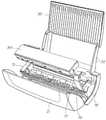
제1 양상에 있어서 본 발명은, 인쇄를 위한 매체를 지지하기 위한 매체입력조립체(Media Input Assembly)를 갖는 본체; 인쇄된 매체를 수집하기 위한 매체출력조립체(Media Output Assembly); 및 상기 본체에 장착되고 상기 매체 상에 이미지를 인쇄하기 위한 프린트헤드를 갖는 프린트 엔진; 을 포함하며, 상기 프린트헤드는 페이지폭 프린트헤드이고 상기 프린트엔진으로부터 제거가능한 프린터 유닛이 제공되어 있다.In a first aspect the present invention provides an apparatus comprising: a body having a media input assembly for supporting a medium for printing; A media output assembly for collecting printed media; And a print engine mounted to the body and having a printhead for printing an image on the medium. Wherein the printhead is a pagewidth printhead and a printer unit is provided that is removable from the print engine.
하나의 형태로, 상기 프린트헤드는 필요한 경우 프린트헤드의 교환을 용이하게 할 수 있도록 프린트 엔진으로부터 제거가능한 카트리지 상에 설치되어 있다. 상기 카트리지는 또한 프린트헤드에 의해 인쇄를 하기 위한 하나 또는 그 이상의 인쇄 유체(Printing Fluid)를 저장하기 위해 배치될 수 있다. 상기 인쇄 유체는 컬러 인쇄를 위한 한 세트(Set)의 색 잉크(Coloured Ink)를 포함한다. 마찬가지로, 인쇄유체는 적외선 잉크(Infrared Ink) 또는 잉크의 응고(Setting)를 용이하게 하기 위해 프린트헤드에 의해 전달될 수 있는 고정액(Fixative)을 포함할 수 있다.In one form, the printhead is mounted on a cartridge removable from the print engine to facilitate replacement of the printhead if necessary. The cartridge may also be arranged to store one or more printing fluids for printing by the printhead. The printing fluid includes a set of color ink for color printing. Likewise, the printing fluid may comprise an infrared ink or a fixative that can be delivered by the printhead to facilitate setting of the ink.
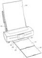
상기 매체입력조립체는 인쇄를 위한 한 장 또는 그 이상의 매체를 수용하도 록 구성되는 매체트레이(Media Tray)일 수 있다. 상기 매체는 A4 크기의 용지 또는 인화지와 같은 용지의 형태로 될 수 있다. 상기 매체트레이는 매체트레이 내에 수용된 매체가 거의 수직 방식으로 프린트 엔진으로 전달되도록 거의 수직방향으로 기울어져 있을 수 있다.The media input assembly may be a media tray configured to accommodate one or more media for printing. The medium may be in the form of paper such as A4 size paper or photo paper. The media tray may be tilted in a substantially vertical direction such that the media contained within the media tray is delivered to the print engine in a substantially vertical manner.
상기 매체출력조립체는 프린트헤드에 의한 인쇄에 이어서 인쇄된 매체를 수용하여 수집하기 위한 하나 또는 그 이상의 매체트레이를 포함할 수 있다. 하나 또는 그 이상의 매체트레이는 가변 크기의 매체(Variable Sized Media)를 수용하기 위해 프린터 유닛의 본체로부터 연장될 수 있다.The media output assembly may include one or more media trays for receiving and collecting printed media following printing by a printhead. One or more of the media trays may extend from the body of the printer unit to accommodate variable sized media.
상기 프린트 엔진은 프린터 유닛의 본체에 견고하게 장착되고 카트리지를 수용하도록 구성되며 인쇄위치에 카트리지를 지지하는 크래들(Cradle)을 포함한다. 상기 크래들은 프린터 유닛의 전체 작동을 제어하며 프린트헤드를 제어하기 위한 적어도 한 개의 SoPEC 장치를 포함하는 제어시스템을 포함한다.The print engine is securely mounted to the body of the printer unit and is configured to receive a cartridge and includes a cradle supporting the cartridge in the print position. The cradle includes a control system that controls the overall operation of the printer unit and includes at least one SoPEC device for controlling the printhead.
상기 크래들은 매체를 매체입력조립체로부터 매체의 표면 상에 이미지가 인쇄되는 프린트헤드를 경유하여 매체출력조립체로 운송하기 위한 매체운송시스템을 더 포함할 수 있다. 이 점에서, 상기 크래들은 매체입력조립체에 가장 가까운 프린트헤드의 상류측에 위치되는 프린트 엔진으로 매체를 수용하기 위한 매체입구(Media Inlet)를 가질 수 있다. 인쇄된 매체를 수집을 위한 매체출력조립체로 전달하는 것을 용이하게 하기 위하여, 상기 크래들은 매체출력조립체에 가장 가까운, 프린트헤드의 하류측에 위치된 매체출구(Media Outlet)를 구비할 수 있다.The cradle may further include a media transport system for transporting the media from the media input assembly to the media output assembly via a printhead in which an image is printed on the surface of the media. In this regard, the cradle may have a media inlet for receiving media with a print engine located upstream of the printhead closest to the media input assembly. To facilitate delivery of printed media to a media output assembly for collection, the cradle may have a Media Outlet located downstream of the printhead closest to the media output assembly.
상기 매체운송시스템은 구동롤러(Drive Roller)와 이 구동롤러를 구동하기 위한 매체운송모터의 작용하여 매체를 운송하기 위해 함께 작용하는 핀치롤러(Pinch Roller)를 포함할 수 있다. 상기 매체운송모터는 프린터 유닛을 통고하여 매체의 전달을 제어하는 제어시스템에 의해 제어되는 브러시리스(Brushless) DC모터이다.The media transport system may include a drive roller and a pinch roller that works together to transport media by acting as a media transport motor for driving the drive roller. The media transport motor is a brushless DC motor controlled by a control system that controls the delivery of media via a printer unit.
상기 크래들은 프린트헤드 상에서 유지보수를 수행하기 위한 프린트헤드 메인티넌스부재(Maintenance Element)를 더 포함할 수 있다. 상기 프린트헤드 메인터넌스부재는 넌-캡핑 위치(Non-Capping Position)로부터 프린트헤드를 사용하지 않을 때 캡핑 위치(Capping Position)로 이동할 수 있는 캡핑면을 포함할 수 있다. 상기 캡핑 위치는 캡핑면이 프린트헤드의 주변과 접촉하는 위치일 수 있고, 이에 의해 그 프린트헤드 둘레에 씰(Seal)을 형성하고 잉크가 프린트헤드 내에서 건조하여 잉크전달노즐을 막는 것을 방지한다. 프린트헤드 메인티넌스부재의 이동은 제어시스템의 제어하에 매체운송모터에 의해 제공될 수 있다.The cradle may further include a printhead maintenance element for performing maintenance on the printhead. The printhead maintenance member may include a capping surface that may move from a non-capping position to a capping position when the printhead is not used. The capping position may be a position where the capping surface is in contact with the periphery of the print head, thereby forming a seal around the print head and preventing the ink from drying in the print head to block the ink delivery nozzle. Movement of the printhead maintenance member can be provided by the media transport motor under control of the control system.
매체는 프린터 유닛의 본체에 장착될 수 있는 매체픽커시스템(Media Picker System)에 의해 매체입력조립체로부터 매체입구로 공급될 수 있다. 상기 매체픽커시스템은 매체입력조립체 내에 포함된 매체를 매체입구로 전달하기 위해 픽커모터에 의해 구동되는 픽커롤러를 포함할 수 있다. 용지 전달의 속도를 제어하기 위해, 상기 픽커모터는 크래들의 제어시스템에 의해 제어되어 이니쇄를 위한 프린트 엔진으로의 매체의 공급 비율을 제어할 수 있다.The media may be supplied from the media input assembly to the media inlet by a Media Picker System, which may be mounted to the body of the printer unit. The media picker system may include a picker roller driven by a picker motor to deliver the media contained in the media input assembly to the media inlet. In order to control the speed of paper transfer, the picker motor can be controlled by a cradle control system to control the rate of supply of media to the print engine for printing.
인쇄에 이어서, 인쇄된 매체는 매체출구기구에 의해 매체출구로부터 매체출력조립체로 전달될 수 있다. 상기 매체출구기구는 출구롤러와 인쇄된 매체를 포착 하여 그 매체를 매체출력조립체로 전달하는 아이들러부재(Idler Element)를 포함할 수 있다. 상기 아이들러부재는 출구롤러와 회전식으로 접촉하여 있는 하나 또는 그 이상의 아이들러 휠(Idler Wheel) 또는 출구롤러와 회전식으로 접촉하여 있는 는 아이들러 롤러일 수 있다. 상기 출구롤러는 프린트 엔진으로부터 인쇄된 매체의 제거를 조정하기 위해 크래들의 제어시스템의 제어하에 매체운송모터에 의해 구동될 수 있다. 이 점에서, 상기 매체출구기구는 크래들의 매체출구에 인접한 프린터 유닛의 본체에 장착될 수 있고, 또는 매체출구에 인접한 크래들에 장착될 수 있다.Following printing, the printed media may be transferred from the media outlet to the media output assembly by the media outlet mechanism. The media outlet mechanism may comprise an idler element (Idler Element) for capturing the exit roller and the printed media and delivering the media to the media output assembly. The idler member may be one or more idler wheels in rotary contact with the exit roller or an idler roller in rotational contact with the exit roller. The exit roller may be driven by the media transport motor under the control of the cradle's control system to coordinate the removal of the printed media from the print engine. In this regard, the media outlet mechanism may be mounted to the body of the printer unit adjacent to the media outlet of the cradle, or may be mounted to the cradle adjacent to the media outlet.
이하에, 본 발명의 통합 특징을 갖는 프린터의 실시형태를 예를 들어 첨부한 도면을 참조하여 설명한다.EMBODIMENT OF THE INVENTION Below, embodiment of the printer which has the integrated characteristic of this invention is described, for example with reference to attached drawing.
제1 양상에 있어서, 본 발명은 인쇄를 위한 매체를 지지하기 위한 매체입력조립체를 갖는 본체;According to a first aspect, the present invention provides an apparatus comprising: a main body having a media input assembly for supporting a medium for printing;
인쇄된 매체를 수집하기 위한 매체출력조립체; 및A media output assembly for collecting printed media; And
매체의 표면 상에 이미지를 인쇄하기 위한 프린트헤드를 갖는 프린트 엔진; 을 포함하며,A print engine having a printhead for printing an image on a surface of the medium; Including;
상기 프린트헤드는 페이지폭 프린트헤드이고 상기 프린트 엔진으로부터 제거가능한 프린터 유닛을 제공한다.The printhead is a pagewidth printhead and provides a printer unit that is removable from the print engine.
선택적으로, 상기 프린트헤드는 카트리지 상에 설치되고 이 카트리지는 프린트 엔진으로부터 제거가능하다.Optionally, the printhead is installed on a cartridge and the cartridge is removable from the print engine.
선택적으로, 상기 카트리지는 인쇄를 위한 하나 또는 그 이상의 인쇄유체를 저장하기 위해 배열되어 있다.Optionally, the cartridge is arranged to store one or more printing fluids for printing.
선택적으로, 상기 프린터는 데스크탑 프린터이고 상기 매체입력조립체는 제1 경사각으로 배치되어 있고, 상기 프린트 엔진은 프린트헤드가 상기 제1 경사각보다 큰 제2 경사각으로 되도록 배열되어 있다.Optionally, the printer is a desktop printer and the media input assembly is disposed at a first tilt angle and the print engine is arranged such that the printhead is at a second tilt angle that is greater than the first tilt angle.
선택적으로, 제1 경사각은 90°와 160°사이이다.Optionally, the first tilt angle is between 90 ° and 160 °.
선택적으로, 제1 경사각은 110°와 130°사이이다.Optionally, the first tilt angle is between 110 ° and 130 °.
선택적으로, 상기 프린트헤드는 그 위에 배열된 적어도 10,000개 잉크전달노즐을 갖는다.Optionally, the printhead has at least 10,000 ink transfer nozzles arranged thereon.
선택적으로, 상기 프린트헤드는 그 위에 배열된 적어도 20,000개 잉크전달노즐을 갖는다.Optionally, the printhead has at least 20,000 ink delivery nozzles arranged thereon.
선택적으로, 상기 프린트헤드는 그 위에 배열된 적어도 50,000개 잉크전달노즐을 갖는다.Optionally, the printhead has at least 50,000 ink delivery nozzles arranged thereon.
선택적으로, 상기 프린트 엔진은 프린트헤드의 작동 제어를 위한 제어시스템을 더 포함하고, 상기 프린트헤드는 사용도중 노즐이 초(Second)당 적어도 5000만번의 비율로 잉크방울을 분사하는지를 제어시스템이 결정하도록 매체의 표면 상에 개별적인 잉크방울을 분사하기 위해 그 위에 배열된 복수의 잉크분사노즐을 갖는다.Optionally, the print engine further comprises a control system for controlling the operation of the printhead, the printhead allowing the control system to determine whether the nozzle ejects ink droplets at a rate of at least 50 million times per second during use. It has a plurality of ink ejection nozzles arranged thereon for ejecting individual ink droplets on the surface of the medium.
선택적으로, 상기 제어시스템은 노즐이 초당 적어도 1억번의 비율로 잉크방울을 분사하는지를 결정한다.Optionally, the control system determines whether the nozzles eject ink droplets at a rate of at least 100 million times per second.
선택적으로, 상기 제어시스템은 노즐이 초당 적어도 3억번의 비율로 잉크방 울을 분사하는지를 결정한다.Optionally, the control system determines whether the nozzles eject ink droplets at a rate of at least 300 million times per second.
선택적으로, 상기 제어시스템은 노즐이 초당 적어도 10억번의 비율로 잉크방울을 분사하는지를 결정한다.Optionally, the control system determines whether the nozzles eject ink droplets at a rate of at least one billion times per second.
선택적으로, 상기 프린트 엔진은 프린트헤드의 작동 제어를 위한 제어시스템을 더 포함하고, 상기 프린트헤드는 사용도중 프린터에 적어도 0.5ppm/kg의 중량비로 인쇄속도를 제공하기 위해 그 인쇄속도가 제어되도록 매체의 표면 상에 개별적인 잉크방울을 분사하기 위해 그 위에 배열된 복수의 잉크분사노즐을 갖는다.Optionally, the print engine further comprises a control system for controlling the operation of the printhead, wherein the printhead is configured such that the print speed is controlled so as to provide the print speed at a weight ratio of at least 0.5 ppm / kg to the printer during use. It has a plurality of ink spray nozzles arranged thereon for spraying individual ink droplets on the surface of the.
선택적으로, 상기 인쇄속도는 프린터에 적어도 1ppm/kg의 중량비로 인쇄속도를 제공하기 위해 제어된다.Optionally, the print speed is controlled to provide the print speed to the printer at a weight ratio of at least 1 ppm / kg.
선택적으로, 상기 인쇄속도는 프린터에 적어도 2ppm/kg의 중량비로 인쇄속도를 제공하기 위해 제어된다.Optionally, the print speed is controlled to provide the print speed to the printer at a weight ratio of at least 2 ppm / kg.
선택적으로, 상기 인쇄속도는 프린터에 적어도 5ppm/kg의 중량비로 인쇄속도를 제공하기 위해 제어된다.Optionally, the print speed is controlled to provide the print speed to the printer at a weight ratio of at least 5 ppm / kg.
선택적으로, 상기 프린트 엔진은 프린트헤드의 인쇄속도를 제어하기 위한 제어시스템을 더 포함하고, 상기 프린트헤드는 사용도중 프린터에 적어도 0.002ppm/cm3의 체적비로 인쇄속도를 제공하기 위해 그 인쇄속도가 제어되도록 매체의 표면 상에 개별적인 잉크방울을 분사하기 위해 그 위에 배열된 복수의 잉크분사노즐을 갖는다.Optionally, the print engine further comprises a control system for controlling the print speed of the printhead, the printhead being configured to provide a print speed at a volume ratio of at least 0.002 ppm / cm3 to the printer during use. It has a plurality of ink ejection nozzles arranged thereon for ejecting individual ink droplets onto the surface of the medium to be controlled.
선택적으로, 상기 인쇄속도는 프린터에 적어도 0.005ppm/cm3의 체적비로 인 쇄속도를 제공하기 위해 제어된다.Optionally, the printing speed is controlled to provide the printer with a printing speed at a volume ratio of at least 0.005 ppm / cm3 .
선택적으로, 상기 인쇄속도는 프린터에 적어도 0.01ppm/cm3의 체적비로 인쇄속도를 제공하기 위해 제어된다.Optionally, the printing speed is controlled to provide the printer with a printing speed at a volume ratio of at least 0.01 ppm / cm3 .
선택적으로, 상기 인쇄속도는 프린터에 적어도 0.02ppm/cm3의 체적비로 인쇄속도를 제공하기 위해 제어된다.Optionally, the printing speed is controlled to provide the printer with a printing speed at a volume ratio of at least 0.02 ppm / cm3 .
선택적으로, 상기 프린트 엔진은 프린트헤드의 인쇄속도를 제어하기 위한 제어시스템을 더 포함하고, 상기 프린트헤드는 사용도중 적어도 50cm2/sec의 면적 인쇄속를 제공하기 위해 그 인쇄속도를 제어되도록 매체의 표면 상에 개별적인 잉크방울을 분사하기 위해 그 위에 배열된 복수의 잉크분사노즐을 갖는다.Optionally, the print engine further comprises a control system for controlling the print speed of the printhead, the printhead being configured to control its print speed to provide an area print speed of at least 50 cm2 / sec during use. It has a plurality of ink ejection nozzles arranged thereon for ejecting individual ink droplets onto it.
선택적으로, 상기 인쇄속도는 적어도 100cm2/sec의 면적 인쇄속를 제공하기 위해 제어된다.Optionally, the printing speed is controlled to provide an area printing speed of at least 100 cm2 / sec.
선택적으로, 상기 인쇄속도는 적어도 200cm2/sec의 면적 인쇄속를 제공하기 위해 제어된다.Optionally, the printing speed is controlled to provide an area printing speed of at least 200 cm2 / sec.
선택적으로, 상기 인쇄속도는 적어도 300cm2/sec의 면적 인쇄속를 제공하기 위해 제어된다.Optionally, the printing speed is controlled to provide an area printing speed of at least 300 cm2 / sec.
선택적으로, 상기 인쇄속도는 적어도 500cm2/sec의 면적 인쇄속를 제공하기 위해 제어된다.Optionally, the printing speed is controlled to provide an area printing speed of at least 500 cm2 / sec.
선택적으로, 상기 매체입력조립체는 인쇄를 위한 한 장 또는 그 이상의 매체를 수용하도록 구성된 매체트레이이다.Optionally, the media input assembly is a media tray configured to receive one or more media for printing.
선택적으로, 상기 매체는 용지이다.Optionally, the medium is paper.
선택적으로, 상기 매체트레이는 실질적으로 수직방향으로 기울어져 있다.Optionally, the media tray is tilted in a substantially vertical direction.
선택적으로, 상기 매체출력조립체는 상기 프린트헤드에 의한 인쇄에 이어서 매체를 수용하여 수집하기 위한 하나 또는 그 이상의 매체트레이를 포함한다.Optionally, the media output assembly includes one or more media trays for receiving and collecting media following printing by the printhead.
선택적으로, 상기 하나 또는 그 이상의 매체트레이는 가변 크기의 인쇄매체를 수용하도록 상기 본체로부터 연장가능하다.Optionally, the one or more media trays are extendable from the body to accommodate print media of varying sizes.
선택적으로, 상기 프린트 엔진은 크래들을 포함하며, 이 크래들은 상기 본체에 견고하게 장착되고 카트리지를 수용하여 그 카트리지를 인쇄위치에 지지하기 위해 구성되어 있다.Optionally, the print engine includes a cradle, which is rigidly mounted to the body and configured to receive a cartridge and support the cartridge in a print position.
선택적으로, 상기 크래들은 프린터의 전체 작동을 제어하는 제어시스템을 포함한다.Optionally, the cradle includes a control system that controls the overall operation of the printer.
선택적으로, 상기 제어시스템은 적어도 한 개의 SoPEC 장치를 포함한다.Optionally, said control system comprises at least one SoPEC device.
선택적으로, 상기 크래들은 매체운송기구를 포함하고, 이 매체운송기구는 매체를 매체입력조립체로부터 프린트헤드를 경유하여 매체출력조립체로 운송한다.Optionally, the cradle includes a media transport mechanism that transports the media from the media input assembly to the media output assembly via the printhead.
선택적으로, 상기 크래들은 매체를 프린트 엔진 안으로 수용하기 위한 것으로 매체입력조립체에 가장 가까운 프린트헤드의 상류측에 위치된 매체입구를 갖는다.Optionally, the cradle has a media inlet located upstream of the printhead closest to the media input assembly for receiving the media into the print engine.
선택적으로, 상기 매체운송시스템은 상기 크래들은 프린트 엔진으로부터 인 쇄된 매체를 전달하기 위한 것으로 매체출력조립체에 가장 가까운 프린트헤드의 하류측에 위치된 매체출구를 갖는다.Optionally, the media transport system has a media outlet located downstream of the printhead closest to the media output assembly for delivering the printed media from the cradle.
선택적으로, 상기 매체운송시스템은 매체를 운송하기 위해 함께 작용하는 구동롤러와 핀치롤러를 포함한다.Optionally, the media transport system includes a drive roller and a pinch roller that work together to transport the media.
선택적으로, 상기 매체운송시스템은 구동롤러를 구동하기 위한 매체운송모터를 포함한다.Optionally, the medium transport system includes a medium transport motor for driving a drive roller.
선택적으로, 상기 매체운송모터는 브러시리스 DC 모터이다.Optionally, the medium transport motor is a brushless DC motor.
선택적으로, 상기 매체운송모터는 매체운송시스템의 작동을 제어하는 제어시스템에 의해 제어된다.Optionally, the medium transport motor is controlled by a control system that controls the operation of the medium transport system.
선택적으로, 상기 크래들은 프린트헤드 메인티넌스부재를 포함한다.Optionally, the cradle includes a printhead maintenance member.
선택적으로, 상기 프린트헤드 메인티넌스부재는 프린트헤드를 캡핑하기 위해 구성되는 캡핑면을 갖는다.Optionally, the printhead maintenance member has a capping surface configured to cap the printhead.
선택적으로, 상기 프린트헤드 메인티넌스부재는 넌-캡핑위치로부터 캡핑위치로 이동가능하다.Optionally, the printhead maintenance member is moveable from the non-capping position to the capping position.
선택적으로, 상기 캡핑위치는 캡핑면이 프린트헤드의 주변과 접촉하여, 상기 프린트헤드 둘레에 씰을 형성하는 위치이다.Optionally, the capping position is a position where the capping surface contacts the periphery of the print head to form a seal around the print head.
선택적으로, 상기 프린트헤드 메인티넌스부재의 이동은 제어시스템의 제어하에 매체운송모터에 의해 제공된다.Optionally, movement of the printhead maintenance member is provided by a media transport motor under control of the control system.
선택적으로, 상기 매체는 매체픽커시스템에 의해 매체입력조립체로부터 매체입구로 공급된다.Optionally, the medium is supplied from the media input assembly to the media inlet by the media picker system.
선택적으로, 상기 매체픽커시스템은 본체에 장착되고 매체입력조립체 내에 포함된 매체를 매체입구에 전달하기 위한 픽커롤러를 포함한다.Optionally, the media picker system includes a picker roller mounted on a body and delivering media contained in the media input assembly to the media inlet.
선택적으로, 상기 매체픽커시스템은 상기 픽커롤러를 구동하는 픽커모터를 갖는다.Optionally, the media picker system has a picker motor for driving the picker roller.
선택적으로, 상기 픽커모터는 인쇄를 위한 프린트 엔진으로의 매체의 공급비율을 제어하기 위해 크래들의 제어시스템에 의해 제어된다.Optionally, the picker motor is controlled by a cradle control system to control the rate of supply of media to the print engine for printing.
선택적으로, 상기 인쇄된 매체는 매체출구기구에 의해 매체출구로부터 매체출력조립체로 전달된다.Optionally, the printed medium is transferred from the media outlet to the media output assembly by a media outlet mechanism.
선택적으로, 상기 매체출구기구는 인쇄된 매체를 포획하여 그 매체를 매체출력조립체에 전달하는 출구롤러와 아이들러 롤러를 포함한다.Optionally, the media outlet mechanism includes an exit roller and an idler roller to capture the printed media and deliver the media to the media output assembly.
선택적으로, 상기 아이들러 부재는 출구롤러와 회전식으로 접촉하여 있는 하나 또는 그 이상의 아이들러 휠이다.Optionally, the idler member is one or more idler wheels which are in rotary contact with the exit roller.
선택적으로, 상기 아이들러 부재는 출구롤러와 회전식으로 접촉하여 있는 아이들러 롤러이다.Optionally, said idler member is an idler roller in rotational contact with an exit roller.
선택적으로, 상기 출구롤러는 크래들의 제어시스템의 제어하에 매체운송모터에 의해 구동된다.Optionally, the outlet roller is driven by the media transport motor under the control of the cradle's control system.
선택적으로, 상기 매체출구기구는 크래들의 매체출구에 인접한 상기 본체에 장착되어 있다.Optionally, the media outlet mechanism is mounted to the body adjacent to the media outlet of the cradle.
선택적으로, 상기 매체출구기구는 상기 매체출구에 인접한 상기 크래들에 장착되어 있다.Optionally, the media outlet mechanism is mounted to the cradle adjacent to the media outlet.
본 발명에 의하면, 데스크탑(Desktop) 상에 바로 수용되는 크기를 갖고 고속으로 고품질의 이미지를 인쇄할 수 있다.According to the present invention, it is possible to print a high quality image at a high speed with a size accommodated directly on a desktop.
바람직한 실시형태의 상세한 설명Detailed Description of the Preferred Embodiments
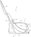
도 4-도 16에 도시된 바와 같이, 본 발명은 분당 60페이지(ppm)의 범위에서 고속으로 포토 품질의 이미지를 인쇄할 수 있는 데스크탑 프린터 유닛(2)으로 구현된다. 다음의 상세한 설명 및 청구범위 내에서 풀 프로세스 컬러 이미지(Full Process Color Image)(스폿 컬러(Spot Colour)가 아님)로 인쇄되고 적어도 80%의 이미지 범위를 요하는 페이지에 대해 인쇄속도와 ppm 모두를 참조할 것이라는 것을 이해하여야 한다. 그러므로, 현존하는 프린터 유닛과의 모든 비교는 이러한 인쇄 요구에 기초된다.As shown in Figs. 4-16, the present invention is implemented with a
다음의 상세한 설명으로부터 바로 이해될 수 있는 바와 같이, 프린터 유닛(2)은 최소의 공간을 차지하지만 그 유닛을 표준 홈 또는 오피스 환경에 쉽게 지원할 수 있게 하는 크기와 중량을 갖도록 구성되어 있다.As can be readily understood from the following detailed description, the
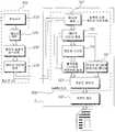
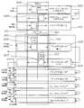
도 1에 개략적으로 도시된 바와 같이, 사용시에, 프린터 유닛(2)은 컴퓨터 시스템(102)과 같은 외부원(External Source)으로부터 수신된 문서를 용지와 같은 인쇄매체 위에 인쇄하기 위해 배열된다. 이 점에서, 프린터 유닛(2)은 컴퓨터 시스템(102)에 의해 전처리(Pre-Processing)된 데이터를 수신하기 위해 그 유닛(2)과 컴퓨터 시스템(102) 사이에 이후에 그 방식을 설명할 전기적 연결을 허용하는 수단 을 포함한다. 하나의 형태로, 외부 컴퓨터 시스템(102)은 문서를 수신하고(단계 103), 그 문서를 버퍼링(Buffering)하여(단계 104) 래스터(Raster)화하고(단계 106) 나서, 그 문서를 압축하는(단계 108)하여 프린터 유닛(2)에 전송하는, 문서 인쇄시에 수반되는 여러 가지의 단계들을 실행하기 위해 프로그램화되어 있다.As shown schematically in FIG. 1, in use, the
본 발명의 하나의 실시형태에 따른 프린터 유닛(2)은 압축된 다층(Multi-layer) 페이지 이미지의 형태로 외부 컴퓨터 시스템(102)으로부터 문서를 수신하며, 여기에서 프린터 유닛(2) 내에 설치된 제어전자기기(72)는 이미지를 버퍼링하고(단계 110) 나서, 이미지를 확장하여(단계 112) 그 이상의 처리를 한다. 확장된 콘톤층(Contone Layer)은 디더링(Dithering)되고(단계 114) 나서 확장단계로부터의 블랙층(Black Layer)은 상기 디더링된 콘톤층에 컴포지트(Composite)된다(단계 116). 코드화된 데이터(Coded Data)는 추가 층을 형성하여 사람의 눈에 실질적으로 안 보이는 적외선 잉크를 사용하여 인쇄(필요하면)되도록 렌더링(Rendering)된다(단계 118). 흑색의 디더링된 콘톤(Contone) 및 적외선 층들은 결합되어(단계 120) 프린트헤드에 공급되는 페이지를 형성하여 인쇄한다(단계 122).The
이러한 특정 구조에 있어서, 인쇄될 문서와 관련된 데이터는 텍스트와 라인아트(Line Art)를 위한 고해상 바이레벨(Bi-Level) 마스크 층과 이미지 또는 배경 색상을 위한 중간 해상 콘톤 컬러(Color) 이미지층으로 분할된다. 선택적으로, 색이 있는 텍스트는 컬러 데이터가 이미지 또는 플랫 컬러(Flat Color)로부터 취해지는 상태로 텍스트와 라인아트의 질감을 위한 중간-고해상 콘톤 질감층(Texture Layer)을 추가함으로써 유지될 수 있다. 인쇄 아키텍처(Architecture)는 이미지 데이나 플랫 컬러 데이터 중 어느 하나를 참조할 수 있는 추상적인 "이미지" 및 "질감" 에 상기 콘톤 층을 표시함으로써 콘톤 층을 일반화한 것이다. 데이터를 콘텐트(Content)에 기초한 층들로의 이러한 분할은 해당분야의 숙련자에 의해 이해될 수 있는 바와 같이 기본 모드(Mode)인 혼합된 래스터 콘텐트(Mixed Raster Content; MRC) 모드를 따른다. MRC 기본 모드처럼, 인쇄 아키텍처는 인쇄될 데이터가 오버랩(Overlap)될 때 몇몇 경우에는 타협을 하게 해준다. 특히, 하나의 형태에서 모든 오버랩은 그러한 타협을 명백하게 구현하는 처리(충돌 해상(Collision Resolution))로 3층 표시로 감소된다.In this particular structure, the data associated with the document to be printed is divided into a high resolution bi-level mask layer for text and line art and a medium resolution contone color image layer for image or background color. Divided. Optionally, colored text can be maintained by adding a mid-high resolution Contone Texture Layer for the texture of text and line art with color data taken from an image or flat color. Print Architecture is a generalization of the contone layer by marking the contone layer in abstract "images" and "textures" that can refer to either image data or flat color data. This division of data into layers based on content follows the Mixed Raster Content (MRC) mode, which is the default mode as can be appreciated by those skilled in the art. Like the MRC basic mode, the print architecture allows compromise in some cases when the data to be printed is overlapped. In particular, in one form all the overlap is reduced to a three-layer display with a process (Collision Resolution) that explicitly implements such a compromise.
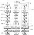
앞서 설명한 바와 같이, 데이터는 주로 소프트웨어에 기초한 컴퓨터 시스템(102)에 의해 수행된 이미지를 전처리하여 압축된 다층 페이지 이미지의 형태로 프린터 유닛(2)에 전달된다. 차례로, 상기 프린터 유닛(2)은 도 2에 더 상세히 도시된 바와 같이 주로 하드웨어에 기초한 시스템을 사용하여 이 데이터를 처리한다.As described above, the data is pre-processed by the
데이터를 수신할 때, 분배기(Distributor, 230)는 소유자 표시로부터의 데이터를 하드웨어-특정 표시로 변환하고, 그 데이터가 이러한 장치들로의 데이터 전송에 대한 어떤 제한들이나 요구들을 관찰하는 동안 올바른 하드웨어 장치로 전송되는 것을 확실하게 한다. 분배기(230)는 변환된 데이터를 복수의 파이프라인(Pipeline, 232)들 중 적합한 것으로 분배한다. 파이프라인들은 서로 일치하고, 본질적으로 데이터 복원(Decompression), 스케일링(Scaling) 및 인쇄할 수 있는 도트(Dot) 출력들의 집합을 생성하기 위한 도트 합성 함수들을 제공한다.Upon receiving the data, the
각 파이프라인(232)는 데이터를 수신하기 위한 버퍼(Buffer, 234)를 포함한 다. 콘톤 디컴프레서(Decompressor, 236)는 컬러 콘톤 면들을 복원하고, 마스크(Mask) 디컴프레서(238)는 모노톤(Monotone)(텍스트) 층을 복원한다. 콘톤 및 마스크 스케일러(Mask Scaler, 240, 242)는 페이지가 인쇄되는 매체의 크기를 고려하여, 복원된 콘톤 및 마스크 면들을 각각 스케일링한다.Each
그 다음에 스케일링된 콘톤 면들은 디더러(Ditherer, 244)에 의해 디더링된다. 하나의 형태로, 확률적 분산-도트 디더(Stochastic Dispersed-Dot Dither)가 사용된다. 클러스터-도트(Clustered-Dot)(또는 진폭-변조된) 디더와 달리, 분산-도트(또는 주파수-변조된) 디더는 거의 도트 해상도의 한계까지 높은 공간 주파수들(즉, 이미지 디테일)을 재생하고, 그 반면에 육안에 의해 공간적으로 통합될 때는, 풀 컬러(Full Dolor) 깊이까지 더 낮은 공간 주파수들을 동시에 재생한다. 확률적 디더 매트릭스(Matrix)는 이미지를 가로질러 타일(Tile)형태로 할 때에 거부될만한 저-주파수 패턴들이 상대적으로 없도록 조심스럽게 설계된다. 그러므로, 그 크기는 전형적으로 특정 수의 강도 레벨(예컨대, 257 강도 레벨에 대해 16×16×8 비트)을 지원하기 위해 요구되는 최소 크기를 초과한다.The scaled contone faces are then dithered by a
그 다음에, 디더링된 면들은 인쇄를 하는 데에 적합한 도트 데이터를 제공하기 위해서 도트-바이-도트(Dot-By-Dot) 기반 상에서 도트 합성기(246)에서 합성된다. 이 데이터는 데이터 분배 및 구동 전자기기(248)로 전송되고, 이는 차례대로 상기 데이터를 올바른 노즐 액츄에이터(Actuators, 250)로 분배하고, 이는 차례대로 잉크가 이후에 상세히 설명하는 방식으로 올바른 시간에 올바른 노즐(252)로부터 방출되도록 한다.The dithered sides are then synthesized in
이해될 수 있는 바와 같이, 인쇄하기 위한 이미지를 처리하기 위해 프린터 유닛(2) 내에 사용된 컴포넌트(Component)들은 데이터를 제공하는 방식에 크게 의존한다. 이 점에서, 프린터 유닛(2)이 추가의 소프트웨어 및/또는 하드웨어 컴포넌트들을 사용하여 상기 프린터 유닛(2) 내에서 더 많은 처리를 행하는 것이 가능하고, 그로써 컴퓨터 시스템(102)에 대한 의존성을 줄일 수 있다. 대안적으로, 상기 프린터 유닛(2)은 보다 적은 처리를 행하여 컴퓨터 시스템(102)에 의존하여서 데이터를 프린터 유닛(2)에 전송하기 전에 이미지를 고급으로 처리하기 위하여 소수의 소프트웨어 및/또는 하드웨어 컴포넌트를 사용할 수도 있다.As can be appreciated, the components used in the
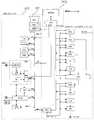
이러한 모든 상황에서, 상술한 작업들을 수행하기 위해 필요한 부품들은 프린터 유닛(2)의 제어전자기기(72) 내에 설치되어 있고, 도 3은 이러한 전자기기의 실시형태의 블럭도를 제공한 것이다.In all such situations, the parts necessary to perform the above-described tasks are installed in the
이러한 구조에 있어서, 하드웨어 파이프라인(232)은 스몰 오피스 홈 오피스 프린터 엔진 칩(Small Office Home Office Print Engine Chip, SoPEC)으로 구현된다. 도시된 바와 같이, SoPEC 장치는 세 개의 별개 서브시스템(Subsystem)으로 구성된다: 중앙처리장치(CPU) 서브시스템(301), 다이내믹 랜덤 액세스 메모리(Dynamic Random Access Memory, DRAM) 서브시스템(302) 및 프린트 엔진 파이프라인(Print Engine Pipeline, PEP) 서브시스템(303).In this structure, the
CPU 서브시스템(301)은 다른 서브시스템의 모든 양상들을 제어하고 구성하는 CPU(30)를 포함한다. 그것은 프린터 유닛(2)의 모든 구성요소들을 인터페이싱하고 동기화하기 위한 일반적인 지원을 제공하며 QA 칩들에 저속 통신을 제어한다. CPU 서브시스템(301)은 또한 범용 입출력(General Purpose Input Output, GPIO)(모터 제어를 포함함), 인터럽트 컨트롤러 장치(Interrupt Controller Unit, ICU), 엘에스에스 마스터(LSS Master) 및 일반적인 타이머들과 같이, CPU를 보조하기 위한 다양한 주변장치들을 포함한다. CUP 서브시스템의 직렬통신블럭(Serial Communication Block, SCB)은 다른 SoPEC 장치들(도시하지 않음)에 인터(Inter) SoPEC 인터페이스(ISI) 뿐만 아니라 호스트(Host)에 풀 스피드(Full Speed) USB1.1 인터페이스를 제공한다.
DRAM 서브시스템(302)은 CPU, 직렬통신블럭(SCB) 및 PEP 서브시스템 내의 블럭들로부터의 요청을 받아들인다. DRAM 서브시스템(302) 및 특히 DRAM 인터페이스 장치(DIU)는 다양한 요청들을 조정하고, 어떤 요청이 DRAM에 액세스를 획득하여야 할지를 결정한다. DIU는 모든 요청자들에 대해 DRAM에 충분한 액세스를 허용하도록 구성된 매개변수(Parameter)들에 기초하여 조정한다. DIU는 또한 페이지 크기, 뱅크(Bank)들의 수 및 리프레쉬율(Refresh Rate)과 같은 DRAM의 실행 사양을 숨긴다.
프린트 엔진 파이프라인(PEP) 서브시스템(303)은 DRAM으로부터 압축된 페이지들을 받아들이고, 그것들을 프린트헤드와 직접 통신하는 프린트헤드 인터페이스에 예정된 소규정 인쇄 라인을 위한 바이-레벨(Bi-Level) 도트들에 렌더(Render)한다. 페이지 확장 파이프라인의 제1 단(Stage)은 콘톤 디코더 유닛(Contone Decoder Unit, CDU), 로스레스 바이레벨 디코더(Lossless Bi-level Decoder, LBD) 및 요구되는 경우 태그 엔코더(Tag Encoder, TE)이다. 프린터 유닛(2)이 넷페이지 용량(Netpage Capability)을 갖는 경우에, CDU는 JPEG-압축된 콘톤(전형적으로 CMYK) 층들 확장시키고, LBD는 압축된 바리-레벨 층(전형적으로 K)를 확장시키고, TE는 이후의 렌더링을 위해 Netpage 태그들을 인코드한다(전형적으로 IR 혹은 K잉크에서). 제1 단으로부터의 출력은 버퍼들의 집합이다: 콘톤 FIFO 유닛(Conton FiFo Unit, CFU), 스포트 FIFO 유닛(Spot FIFO Unit, SFU), 및 태그 FIFO 유닛(Tag FIFO Unit(TFU). CFU 및 SFU 버퍼들은 DRAM에서 실현된다.The print engine pipeline (PEP)
제2 단은 핼프톤 컴포지터 유닛(Halftone Compositor Unit, HCU)이고, 이는 콘톤 층을 디더링하고 위치 태그들과 얻어진 바이-레벨 디더링된 층에 대한 바이-레벨 스폿 층(Spot Layer)을 합성한다.The second stage is a Halftone Compositor Unit (HCU), which dithers the contone layer and synthesizes the bi-level spot layer for the location tags and the resulting bi-level dithered layer.
다양한 복합옵션(Compositing Option)들이 SoPEC 장치가 사용되는 프린트헤드에 의존하여 실행될 수 있다. 모든 채널(Channel)들이 프린트헤드 상에 존재할 수는 없다고 하더라도, 바이-레벨 데이터의 6 채널들까지는 이 단으로부터 생산된다. 예컨대, 프린트헤드는 K가 CMY 채널들로 푸시(Push)되고 IR이 무시된 상태에서, 단지 CMY일 수도 있다. 대안적으로, 인코드된 태그들은 IR 잉크가 이용될 수 없다면(혹은 테스트 목적을 위한 경우) K로 인쇄될 수도 있다.Various compositing options can be implemented depending on the printhead in which the SoPEC device is used. Although not all channels can be present on the printhead, up to six channels of bi-level data are produced from this stage. For example, the printhead may be just CMY, with K pushed to CMY channels and IR ignored. Alternatively, encoded tags may be printed in K if IR ink is not available (or for test purposes).
제3 단으로, 데드 노즐 보상기(Dead Nozzle Compensator, DNC)는 프린트헤드에 있는 데드 노즐들을 컬러 과잉 및 주변 도트들 안으로의 데드노즐 데이터의 에러 확산에 의해 보상한다.In a third stage, the Dead Nozzle Compensator (DNC) compensates for dead nozzles in the printhead by color excess and error diffusion of dead nozzle data into surrounding dots.
그 결과로서 생기는 바이-레벨 6 채널 도트-데이터(전형적으로 CMYK, 적외선, 염료(Fixative))는 버퍼링되고 도트라인 라이터 유닛(Dotline Writer Unit, DWU)을 거쳐서 DRAM에 저장된 라인 버퍼들의 집합으로 써진다.The resulting bi-level 6-channel dot-data (typically CMYK, infrared, dye) is buffered and written into a set of line buffers stored in DRAM via a Dotline Writer Unit (DWU). .
마지막으로, 도트-데이터는 DRAM으로부터 반대로 로딩되고, 도트 FIFO를 거쳐서 프린트헤드 인터페이스로 보내진다. 도트 FIFO는 시스템 클럭율(Clock Rate)(pclk)에서 라인 로더 유닛(Line Loader Unit, LLU)으로부터 데이터를 받아들이고, 그 반면에 프린트헤드 인터페이스(PrintHead Interface, PHI)는 FIFO로부터 데이터를 제거하고, 그것을 시스템 클럭율의 2/3배의 비율로 프린트헤드로 전송한다.Finally, the dot-data is loaded inversely from the DRAM and sent to the printhead interface via the dot FIFO. The dot FIFO accepts data from the Line Loader Unit (LLU) at the system clock rate (pclk), while the PrintHead Interface (PHI) removes data from the FIFO, and the system It is sent to the printhead at a rate that is two-thirds the clock rate.
바람직한 형태에 있어서, DRAM은 크기가 2.5Mbytes이고, 그 중 약 2Mbytes가 압축된 페이지 저장 데이터에 이용될 수 있다. 압축된 페이지는 다수의 밴드(Band)들이 메모리에 저장된 상태에서, 둘 또는 그 이상의 밴드로 수신된다. 상기 페이지의 밴드가 인쇄를 위해 PEP 서브시스템(303)에 의해 소비될 때, 새로운 밴드가 다운로드(Download)될 수 있다. 그 새로운 밴드는 현재 페이지 또는 다음 페이지를 위한 것일 수 있다.In a preferred form, the DRAM is 2.5 Mbytes in size, of which about 2 Mbytes can be used for compressed page store data. Compressed pages are received in two or more bands, with multiple bands stored in memory. When a band of the page is consumed by the
밴딩을 사용하면, 완전히 압축된 페이지가 다운로드되기 전에 한 페이지의 인쇄를 시작하는 것이 가능하지만, 데이터가 항상 인쇄를 위해 이용가능한지를 확인하는데 주의를 기울여야 하고, 그렇지 않으면 버퍼 언더-런(Under-Run)이 일어날 수 있다.Using banding, it is possible to start printing one page before the fully compressed page is downloaded, but care must be taken to ensure that data is always available for printing, otherwise buffer under-run ) May occur.
내장된 USB1.1 장치는 호스트 PC로부터 압축된 페이지 데이터 및 제어 명령들을 받아들이고, DRAM(또는 멀티 SoPEC 시스템에서는 이하에서 설명되는 바와 같이 또 다른 SoPEC)으로 데이터 전송을 용이하게 한다.The built-in USB1.1 device accepts compressed page data and control commands from the host PC and facilitates data transfer to DRAM (or another SoPEC as described below in a multi SoPEC system).
다수의 SoPEC 장치는 선택적인 실시형태에 사용될 수 있고, 특별한 실행에 따른 상이한 기능들을 수행할 수 있다. 예컨대, 몇몇 경우에, SoPEC 장치는 단순히 온보드(Onboard) DRAM용으로 사용될 수 있고, 그 반면에 또 다른 SoPEC 장치는 상기 설명된 다양한 데이터 복원 및 포맷팅(Formatting) 기능을 수행한다. 이는 그 페이지의 모든 데이터를 수신하기 전에 프린터가 인쇄를 시작하고, 그 데이터의 나머지가 제때에 수신되지 않은 경우에서 발생할 수 있는 버퍼 언더-런의 가능성을 줄일 수 있다. 메모리 버퍼링 능력을 위해 여분의 SoPEC 장치를 부가하는 것은 부가되는 칩의 다른 능력들 중 어느 것도 이용되지 않더라도, 버퍼링될 수 있는 데이터의 양을 2배로 한다.Multiple SoPEC devices may be used in alternative embodiments and may perform different functions in accordance with a particular implementation. For example, in some cases, SoPEC devices may simply be used for onboard DRAM, while another SoPEC device performs the various data recovery and formatting functions described above. This may reduce the likelihood of a buffer under-run that may occur if the printer starts printing before receiving all the data of the page and the rest of the data is not received in time. Adding an extra SoPEC device for memory buffering capability doubles the amount of data that can be buffered, even if none of the other capabilities of the chip being added are used.
각 SoPEC 시스템은 프린터 기구들의 품질, 인쇄 도중 프린트헤드 노즐들이 손상되지 않을 정도의 잉크 제공의 품질 및 프린트헤드와 기구들이 손상되지 않도록 확실하게 하기 위한 소프트웨어의 품질을 확실하게 하기 위해 서로 협력하도록 설계된 몇 가지 품질 보증(QA: Quality Sssurance)을 가질 수 있다.Each SoPEC system is designed to work together to ensure the quality of the printer mechanisms, the quality of the ink supply that the printhead nozzles will not be damaged during printing, and the quality of the software to ensure that the printhead and the mechanisms are not damaged. There may be quality assurance (QA).
보통, 각 인쇄 SoPEC는 관련된 프린터 QA를 가질 것이고, 그것은 최대 인쇄속도와 같은 프린터 속성들의 정보를 저장한다. 시스템과 함께 사용하기 위한 잉크 카트리지는 또한 잉크 QA 칩을 포함할 것이고, 그것은 남아있는 잉크의 양과 같은 카트리지 정보를 저장한다. 프린트헤드는 또한 데드노즐 매핑(Mapping) 및 프린트헤드 특성들과 같은 프린트헤드-특정 정보를 저장하는 ROM(효율적으로는 EEPROM)으로써 동작하도록 구성되는 QA 칩을 가지고 있다. SoPEC 장치에서 CPU는선택적으로 직렬 EEPROM으로써 효율적으로 동작하는 QA 칩으로부터의 프로그램 코 드를 로딩하여 실행할 수 있다. 마지막으로, SoPEC 장치에서 CPU는 논리 QA 칩(즉, 소프트웨어 QA 칩)을 실행한다.Normally, each printing SoPEC will have an associated printer QA, which stores information of printer attributes such as maximum print speed. The ink cartridge for use with the system will also include an ink QA chip, which stores cartridge information such as the amount of ink remaining. The printhead also has a QA chip configured to operate as a ROM (efficiently EEPROM) that stores printhead-specific information, such as dead nozzle mapping and printhead characteristics. In SoPEC devices, the CPU can optionally load and execute program code from a QA chip operating efficiently as a serial EEPROM. Finally, in SoPEC devices, the CPU executes a logic QA chip (ie, a software QA chip).
대체로, 시스템에서의 모든 QA 칩들은 플래시 메모리(Flash Memory)의 콘텐츠(Contents)들만이 서로를 구별하는 상태로, 물리적으로는 동일하다.In general, all QA chips in a system are physically identical, with only the contents of Flash memory distinguishing from each other.
각 SoPEC 장치는 두 개의 LSS 시스템 버스(Bus)들을 가지고 있고, 그것이 시스템 인증 및 잉크 사용 산정을 위해서 QA 장치들과 통신할 수 있다. 많은 수의 QA 장치들은 버스마다 사용될 수 있고, 시스템에서의 그들의 위치는 프린터 QA 및 잉크 QA 장치들이 분리된 LSS 버스들 상에 있어야만 한다는 것을 제외하고는 제한되지 않는다.Each SoPEC device has two LSS system buses, which can communicate with QA devices for system authentication and ink usage estimation. A large number of QA devices can be used per bus, and their location in the system is not limited except that printer QA and ink QA devices must be on separate LSS buses.
사용시에, 논리 QA는 남아있는 잉크를 결정하기 위해 잉크 QA와 통신한다. 잉크 QA로부터의 응답은 프린터 QA를 참조하여 인증된다. 프린터 QA로부터의 확인은 논리 QA에 의해 인증되고, 그에 의해 간접적으로 잉크 QA로부터의 응답에 부가적인 인증 레벨을 부가한다.In use, the logical QA communicates with the ink QA to determine the remaining ink. The response from the ink QA is authenticated with reference to the printer QA. The confirmation from the printer QA is authenticated by the logic QA, thereby indirectly adding an additional authentication level to the response from the ink QA.
프린트헤드 QA 이외에 QA 칩들 사이에 지나간 데이터는 디지털 서명의 방식으로 인증된다. 바람직한 실시형태에 있어서, 다른 설계들이 대신 사용될 수 있더라도, HMAC-SHA1 인증은 데이터용으로 사용되고, RSA는 프로그램 코드용으로 사용된다.In addition to the printhead QA, data passed between QA chips is authenticated by digital signature. In a preferred embodiment, HMAC-SHA1 authentication is used for data and RSA is used for program code, although other designs may be used instead.
이해될 수 있는 바와 같이, SoPEC 장치는 프린터 유닛(2)의 전체 작동을 제어하고 본질적인 데이터 처리작업을 수행하는 것은 물론 프린터 유닛(2)의 개개의 부품들의 작동을 동기화하고 제어하기도 하여 인쇄된 매체의 조정을 용이하게 한 다. 본 명세서의 설명의 나머지 부분에서는, 프린터 유닛의 작동을 제어하기 위해 프린터 유닛(2) 내에 사용되는 어떤 다른 전자기기와 SoPEC 장치를 참조하도록 제어전자기기(72) 용어를 사용할 것이다.As can be appreciated, the SoPEC device controls the overall operation of the
도 4-도 16은 메인 본체(3), 인쇄를 위한 인쇄 매체를 보유하고 지지하기 위한 매체입력조립체 및 프린터 유닛에 의한 인쇄에 이어서 인쇄 매체를 수집하는 매체출력조립체를 포함하는 잉크젯 프린터 유닛(2)를 도시한 것이다. 메인 본체(3)는 프린트 엔진(70)과 관련된 전원(15)과 제어전자기기(72)뿐만 아니라, 인쇄매체를 매체입력조립체(4)로부터 인쇄매체가 인쇄되는 프린트 엔진(70)을 경유하여 인쇄된 매체가 수집되는 매체출력조립체(5)로 전달하기 위해 작용하는 용지조정장치를 수용하도록 배열되어 있다. 이러한 배열은 단일 컬러 텍스트로부터 풀 컬러 포토 이미지들까지 다양한 이미지들을 인쇄하기 위해 홈 또는 오피스 환경에 바로 사용될 수 있는 컴팩트(Compact) 프린터 유닛을 제공한다.4 to 16 show an
도 4-도 12와 관련하여, 메인 본체(3)의 구조는 하부 프레임(Frame) 유닛(6) 상에 수용되도록 형상화되는 상부 프레임 유닛(7)에 의해 형성되어 있다. 상부 및 하부 프레임 유닛(6, 7)은 커버(11)를 수용하는 베이스(8), 후면(9) 및 개구(10)를 함께 형성한다. 개구(10)는 프린트 엔진(70)과 관련된 컴포넌트를 포함하는 내부 캐버티(Cavity, 12)에 대한 입구를 제공한다.4 to 12, the structure of the
베이스(8)는 하부 프레임 유닛(6)의 하류측상에 형성되고 프린터 유닛이 홈 또는 오피스 환경에서의 데스크(Desk) 표면과 같이 실질적으로 수평한 표면상에 위치될 때 프린터 유닛(2)를 지지하는 하부면(13)을 갖는다. 하나 또는 그 이상의 푸트 지지부(Foot Support, 14)는 프린터 유닛에 부가적인 안정성을 제공하기 위해 하부면(13)으로부터 뻗어있다. 상기 푸트 지지부(14)는 프린터 유닛과 지지면 사이에 마찰 접촉을 증대시키기 위해 고무 등의 마찰유도재(Friction Inducing Material)로 형성된다.The
도 5 및 도 7에 도시된 바와 같이, 메인 본체(3)의 후면(9)은 하부 프레임 유닛(6)과 상부 프레임 유닛(7)의 후면에 의해 규정된다. 전원공급유닛(15)은 후면(9)의 일부를 형성하고 프린터 유닛(2)에 전원을 공급하기 위해 하부 프레임 유닛(6)에 마련된 오목부 내에 끼워 맞추어지게 형상화되어 있다. 상기 전원공급유닛(15)은 하부 프레임 유닛(6)의 형상화된 오목부 내에 견고하게 수용되지만, 이 전원공급유닛(15)이 프린터 유닛(2)에 전원을 저장할 수 있는 재충전가능한 타입으로 이루어질 수도 있고, 그러므로 상기 유닛(15)은 필요한 경우에 교체하기 위한 프레임 유닛(6)으로부터 제거가능하게 될 수 있다. 전원 커넥터 소켓(16)은 적절한 도선(Lead, 도시하지 않음)을 경유하여 외부전원에 연결하기 위한 전원공급유닛(15)에 설치되어 있다. 또한 데이터 커넥터 소켓(17)은 하부 프레임 유닛(6) 내에 형성되고 컴퓨터 시스템(102)과 같이 외부원에 프린터 유닛(2)을 접속하기 위한 수단을 제공하여 앞서 설명한 바와 같은 방식으로 프린터 유닛(2)에 데이터와 명령을 제공한다. 상기 데이터 커넥터 소켓(17)은 프린터 유닛(2)을 컴퓨터 단자(102) 또는 컴퓨터 단자들의 네트워크에 접속하여 그로부터 데이터와 명령을 받을 수 있게 하는 표준형 이더넷(Standard Ethernet)과 USB 장치 소켓의 형태로 있다. 이러한 정보는 상부 프레임 유닛(7)의 후면상의 커버 플레이트(Cover Plate, 20) 아래 에 마련된 WIFI 카드(18) 및/또는 Bluetooth(등록상표) 카드(19)를 사용함으로써 무선방식으로 프린터 유닛(2)에 의해 수신될 수도 있다. 이 구조들의 각각에 있어서, 수신된 모든 데이터는 프로세싱 및 인쇄를 위해 소켓(17)과 카드(18, 19)로부터 프린터 유닛(2)의 제어시스템으로 전달된다.As shown in FIGS. 5 and 7, the
도 4, 6, 8-10에 도시된 바와 같이, 메인 본체(3)의 커버(11)는 하부 프레임 유닛(6)에 힌지(Hinge)식으로 연결된 뚜껑(Lid, 21)을 포함한다. 이 뚜껑(21)은 상부 프레임 유닛(7)의 상부 모서리와 결합하도록 형상화되는 굴곡진 상면(22)과 각진 정면(23)과 두 개의 단면(24)을 갖는다. 뚜껑(21)은 상부 프레임 유닛(7)에 대해 상면(22)의 후면 모서리를 따라 선회가능하게 연결되어 있다. 이러한 선회식 연결은 메인 본체(3)의 내부 캐버티(12)에 대한 접근을 제공하기 위해 뚜껑(21)을 후방으로 선회할 수 있게 한다.As shown in FIGS. 4, 6 and 8-10, the
각진 정면(23)은 그 안에 오목부(25)가 형성되어 있다. 이 오목부(25)는 사용자와 프린터 유닛(2) 사이에 통신을 가능하게 하는 유저 인터페이스 유닛(User Interface Unit, 26)을 수용한다. 상기 유저 인터페이스 유닛(26)은 사용자에게 정보를 전달하는 LCD 터치 스크린(Touch Screen)이고 사용자로 하여금 디스플레이 스크린상에 옵션(Option) 선택을 통해 프린터 유닛(2)에 정보를 직접 입력할 수 있게 한다. 유저 인터페이스 유닛(26)가 사용자에게 표시하고 사용자가 프린터 유닛에 입력할 수 있는 정보의 종류는 바뀔 수 있지만, 전형적으로 이것은 프린터 유닛(2)에 저장된 잉크의 상태, 어떠한 용지 걸림 등은 물론 잉크 재충전 절차에 대한 정보를 수정하기 위한 필요성에 관련될 수 있다. 디스플레이가 특정 언어로 프 로그램됨으로써, 그 프린터 유닛을 사용하여야 하는 국가에 특정될 수 있는 프린터 유닛에 별개의 마킹(Marking)이나 텍스트를 제공하는 필요성을 극복할 수 있으므로, 터치 스크린 LCD의 사용은 특히 유저 인터페이스로서 이점이 있다. 그러나, 유저 인터페이스 유닛(26)이 사용자에게 프린터 유닛(2)과 상호작용할 수 있게 하는 통상의 버튼과 그와 유사한 것 등의 다수의 다른 형태로 될 수 있다는 것을 이해하여야 한다.The angled
뚜껑(21)의 각진 정면(23)에는 또한 사용자에게 프린터의 상태의 시각적인 표시를 제공하는 시각적 표시기 유닛(Visual Indicator Unit, 27)이 설치되어 있다. 상기 시각적 표시기 유닛(27)은 뚜껑(21)의 표면을 따라 뻗어 있고 광원(29)으로부터 광을 방출하는 길다란 튜브 또는 패널(Panel, 28)의 형태로 있다. 시각적 표시기 유닛(27)으로부터 방출된 광의 색상 및/또는 강도는 유저 인터페이스 유닛(26)을 참고할 필요성 없이 프린터 유닛(2)의 상태의 순간 표시를 사용자에게 제공하는 방식으로 제어될 수 있다.The angled
시각적 표시기 유닛(27)의 구성은 도 17a 및 도 17b에 도시되어 있다. 도시된 바와 같이, 이 유닛(27)은 광원(29)과 길다란 패널(28)로 이루어져 있다. 광원(29)은 인쇄회로판(PCB, 31)의 표면상에 배열된 세 개의 발광다이오드(LED, 30)의 형태로 있다. LED(30)는 폭넓은 광 스펙트럼이 그 패널(28)로부터 방출될 수 있게 하는 적색, 녹색 및 청색 LED이다. 그러나, 그와 유사한 작용을 수행하기 위해 단일의 LED 또는 다른 색상을 갖는 LED도 사용될 수 있다. PCB(31)는 프린터 유닛(2)에 대해 제어 전자기기(72)를 포함하는 같은 PCB일 수 있고, 또는 그 제어 전자기기(72)의 제어하에 LED(30)를 작동시키기 위해 적당한 전자기기를 포함하는 별도의 PCB일 수도 있다. 길다란 패널(28)은 LED(30)로부터의 광이 그 길이를 따라 이동하여 그 패널의 표면으로부터 전달될 수 있게 하는 재료로 형성되어 있다. 상기 패널(28)은 LED(30)로부터 방출된 광을 수집하기 위해 LED(30) 상에 놓여지는 중공 튜브(Hollow Tube) 또는 파이프의 형태로 될 수 있다. 튜브 또는 파이프의 내부면은 광의 일부가 패널(28)의 길이를 따라 반사되고 패널(28)로부터 통과하여 패널(28)의 표면을 따라 사용자에 의해 바로 보여질 수 있게 패널(28)을 조명할 수 있도록 하는 필름(Film)으로 코팅될 수 있다.The configuration of the
사용시에, LED(30) 각각은 프린터 유닛(2)의 상태를 나타내는 패널(28)로부터 광을 방출하기 위해 제어될 수 있다. 예컨대, 프린터 유닛이 대기모드(Standby Mode)에 있다는 것을 사용자에게 보여주기 위해 패널(28)이 청색 광을 방출하도록 청색 LED가 활성화될 수 있다. 인쇄 도중, 녹색 LED는 패널(28)로부터 녹색 광을 방출하기 위해 활성화되고 용지 걸림이나 프린터 오류 등의 문제가 있는 경우에는, 패널(28)로부터 적색 광을 방출하도록 적색 LED가 활성화될 수 있다. 부가적으로, 장식효과를 일으키기 위하여, 각각의 LED는 폭넓은 스펙트럼을 가로질러 다양한 색상을 갖는 광을 방출하도록 여러 가지의 조합으로 작동될 수도 있다. 광이 프린터 유닛상에 설치된 단일의 LED의 경우에서와 같이 점원(Point Source)이라기 보다는 대면적에 걸쳐 방출되기 때문에, 사용자는 프린터의 상태를 시각적으로 검출하여 필요한 경우에 프린터를 관리할 가능성이 크다. 이러한 시스템은 능률적인 작업장을 확보하는 데 있어 중요한 기능을 실행하며, 또한 심미적으로 즐거운 프린터 유 닛을 제공한다.In use, each of the
인쇄를 위한 프린터 유닛(2)에 인쇄된 매체를 제공하기 위하여, 매체입력조립체(4)는 프린터 유닛(2)의 후면(9)으로부터 뻗어 있다. 매체입력조립체(4)는 프린터 유닛(2)에 의해 인쇄를 위해 한 장 또는 그 이상의 인쇄된 매체(34)를 수용하기 위한 표면을 함께 형성하는 트레이부(Tray Portion, 32)와 매체 지지플랩(Support Flap, 33)으로 이루어져 있다. 매체입력조립체(4)는 메인 본체(3)로부터 수직방향으로 뻗어 있고 사용시에, 여러 장의 인쇄된 매체(34)가 도 16에 도시되어 있고 이후에 더 상세히 설명되는 바와 같이, 수직방향으로 매체입력조립체(4)에 의해 지지되고 하향통로(Downward Pass)를 거쳐 프린터로 끌어 당겨진다.In order to provide a printed medium to the
도 11에 더 명확히 도시된 바와 같이, 매체입력조립체(4)의 트레이부(32)는 상부 프레임 유닛(7)과 일체로 형성되어 있고, 그러므로 트레이부(32)의 후면은 메인 본체(3)의 후면(9)의 일부를 형성한다. 트레이부(32)는 일반적으로 인쇄된 매체(34)를 수용하기 위한 수용부(Receptacle)를 형성하고 매체(34)가 놓여지는 작업면(35)과 그 일단부에, 매체(34)를 수직위치로 유지하기 위해 매체(34)의 가장자리를 수용하도록 구성된 매체지지면(36)을 포함한다. 또한 트레이부(32)는 프린터 유닛(2)에 의해 수용될 수 있는 인쇄된 매체의 최대 폭을 규정하는, 한 쌍의 평행하게 뻗어 있는 측벽(37, 38)을 포함한다.As shown more clearly in FIG. 11, the
도 16에 더 명확히 도시된 바와 같이, 매체지지면(36)은 인쇄를 위해 한 장의 인쇄된 매체(34)를 트레이부(32)에서부터 프린트 엔진(70)으로 전달하는 것을 돕기 위해, 트레이부(32)의 작업면(35)에 둔각(Obtuse Angle)으로 배치되어 있다. 작업면(35)은 인쇄를 위해 픽커기구(Picker Mechanism, 60)와 작용하여 한 장의 인쇄된 매체(34)를 작업면(35)에서부터 프린트 엔진(70)으로 전달하는 것을 용이하게 하기 위해 그 안에 통합된 아이들러 롤러(Idler Roller, 39)를 갖고 있다. 매체지지면(36)을 따라 간격을 두고 배치된 것은 매체지지면(36)으로부터 뻗어 있고 매체지지면(36) 위에 매체(34)의 선단부를 지지하는 다수의 돌출된 스트립(Strip, 40)이다. 이 스트립(40)은 매체(34)의 선단부가 픽커기구(60)의 작용하에 스트립(40)의 표면을 따라 미끄러져 트레이부(32)로부터의 매체(34)의 전달을 용이하게 할 수 있도록 작용한다. 마찰면을 제공하기 위해 픽커기구(60)에 인접한 스트립(40)의 표면상에는 패드(41)가 설치되어 있어 여러 장이 트레이부(32)의 작업면(35) 위에 지지될 때 가장 윗 장의 매체(10)의 분리를 용이하게 한다. 상기 패드(41)는 고무, 펠트(Felt) 또는 코르크(Cork) 타입의 재료의 형태로 될 수 있다.As is more clearly shown in FIG. 16, the
여백 슬라이더(Margin Slider, 42)는 일체형 후크부재(Hook Element, 43)에 의해 트레이부(32)의 작업면(35)상에 끼워지도록 구성된다. 상기 슬라이더(42)의 위치지정 돌기(Locating Lug, 도시하지 않음)를 수용하여 상기 슬라이더(42)를 작업면(35)과 결합하는 상태로 유지하기 위해 작업면(35)에 홈이 형성된 오목부(도시하지 않음)를 마련할 수도 있다. 이러한 구조는 폭을 변화시키는 인쇄매체(34)를 수용하기 위해 슬라이더(42)가 작업면(35)을 가로질러 제어되는 방식으로 이동되게 할 수 있다. 여백 슬라이더(42)는 트레이부(32)의 높이만큼 뻗어 있고, 인쇄매체(34)의 측면 가장자리(Side Edge)에 접하기 위해 트레이부(34)의 작업면(35)으로부터 바깥쪽으로 뻗어있는 벽부(Wall Portion, 45)를 구비하고 있다. 이 구조는 여러 장의 매체를 프린트 엔진(70)에 제어되는 상태로 전달하는 것을 확실하게 하기 위해 인쇄매체(34)가 트레이부(32) 내에 적당하게 정렬되는 것을 확실하게 한다.The
도 11에 도시된 바와 같이, 트레이부(32)의 측벽(37, 38)에는, 매체 지지 플랩(Media Support Flap, 33)이 트레이부(32)에 연결될 수 있도록 그 내면에 위치지정 돌기(46)가 구비되어 있다. 이 점에서, 상기 매체 지지 플랩(33)은 상기 돌기(46)를 수용하는 그 단부로부터 뻗어있는 한 쌍의 오목진 탭(Recessed Tab, 47)을 포함하고, 이에 의해 매체 지지 플랩(33)을 트레이부(32)의 상단부에 고착할 수 있다. 이러한 구조에 따라, 매체 지지 플랩(33)은 매체입력조립체(4, 도 4에 도시된 바와 같음)에 적재되는 인쇄매체(34)를 지지하는 연장된 위치, 또는 포장 또는 출하를 위한 수축된 위치로 이동될 수 있을 정도로 트레이부(32)의 말단부(Distal End)를 중심으로 선회할 수 있고, 여기서 상기 매체 지지 플랩(33)은 트레이부(32)의 상단부(도시하지 않음)에 수용된다.As shown in FIG. 11, on the
상기 매체 지지 플랩(33)은 트레이부(32)의 길이보다 긴 길이를 갖는 인쇄매체(34)를 지지하기 위해 트레이부(32)의 말단부를 지나 뻗어있다. 이 구조는 인쇄매체(34)가 도 8에 도시된 바와 같이 거의 직립위치로 유지되는 것을 확실하게 한다. 이 점에서, 매체 지지 플랩(33)의 표면은 그 플랩(33)의 표면을 따라 종방향으로 뻗어있는 다수의 등간격의 핀부재(48)를 구비하고 있다. 상기 핀부재(48)의 각각은 인쇄 지지 플랩(33)의 표면으로부터 동량(同量)만큼 뻗어있어 트레이부(32)의 작업면(35)과 연속하는 인쇄매체(34)에 평탄면을 제공한다. 상기 매체 지지 플 랩(32)이 프린터 유닛(2)의 포장 또는 운송을 위해 접혀질 때, 상기 매체 지지 플랩(33)의 내면이 트레이부(32)의 측벽(37, 38)을 수용하기 위해 그 가장자리 영역에 형성된 적당한 슬롯(Slot)을 갖는 연속적인 성형면(Moulded Surface)일 수도 있다는 것을 직시할 수 있다.The
인쇄된 매체는 도 4에 도시된 바와 같이 프린터 유닛(2)의 정면에서 메인 본체(3)의 베이스(8)에 위치되는 매체출력조립체(5)에 의해 수집된다. 매체출력조립체(5)는 트레이 하우징(50) 및 두 개의 연장가능한 출력 트레이인 상부 출력 트레이(51)와 하부 출력 트레이(52)로 이루어져 있는데, 이들 출력 트레이는 연장된 위치에 있지 않을 때 트레이 하우징(50) 내에 유지된다.The printed media is collected by the
도 10 및 도 11에 도시된 바와 같이, 트레이 하우징(50)은 하부 프레임 유닛(6)과 일체로 형성되고 프린터 유닛(2)의 후면에서부터 그 정면을 지나 가장자리로 까지 뻗어있다. 상면(53)의 전단부(Front Edge)는 개방되어 있고 트레이 하우징(50) 내에 유지된 상부 및 하부 출력 트레이(51)(52)에 대한 접근을 가능하게 하기 위해 그 안에 오목부(56)가 형성되어 있다.As shown in FIGS. 10 and 11, the
상부 출력 트레이(51)는 두 개의 측벽(54, 55)에 의해 트레이 하우징(50) 내에 수용되어 유지되도록 형상화되어 있다. 두 개의 측벽(54, 55)은 그 안에 트레이 하우징(50)의 길이를 연장하는 홈들(도시하지 않음)을 마련하고 있다. 상부 출력 트레이(51)는 그 종단부(Longitudinal Edges)가 상기 홈들내로 이동하여 트레이 하우징(50)에 대하여 트레이(51)를 이동시킬 수 있도록 상기 홈들내에 수용되기 위한 크기로 되어 있다. 상부 출력 트레이(51)의 종단부와 홈들은 트레이(51)가 트 레이 하우징(50)으로부터 연장가능하지만 트레이 하우징(50)으로부터 제거가능하지 않도록 배열되어 있다. 이러한 구조에서 상기 트레이(51)는 그 수축된 위치에 있을 때 트레이 하우징(50) 내에 완전히 끼워진다.The
하부 출력 트레이(52)는 상부 출력 트레이(51)와 유사한 방식으로 구성되어 있다. 그러나, 이러한 구조에서, 하부 출력 트레이(52)는 상부 출력 트레이(51)의 종단부에 마련된 두 개의 홈 내에 수용되어 있다. 도 9에 도시된 바와 같이, 하부 출력 트레이(52)는 하부 트레이(52)가 상부 트레이내로 이동할 수 있도록 상부 출력 트레이(51)보다 줄어든 폭과 두께를 갖는다. 하부 출력 트레이(52)는 수축된 상태에 상부 출력 트레이(51) 내에 완전히 끼워지도록 배열되어 있고 상부 출력 트레이(51) 또한 하부 출력 트레이(52)의 전단부에 설치된 정지부재(58)에 대한 접근을 가능하게 하기 위해 그 전단부를 따라 오목부(57) 내에 설치되어 있다. 하부 출력 트레이(52)와 상부 출력 트레이(51)는 상술한 바와 같이 유사한 방식으로 하부 트레이(52)가 상부 트레이(51)로부터 연장되게 할 수 있지만 상부 트레이로부터 제거되는 것을 방지되게 할 수 있는 방식으로 구성되어 있다. 수축과 연장을 허용하는 트레이들의 그 밖의 구조 또한 가능하며 본 발명의 범위 내에 포함된다고 생각된다.The
사용하기 전에, 매체출력조립체(5)는 도 4에 도시된 바와 같이 수축된 상태에 있는다. 매체출력조립체(5)는, 사용자가 정지부재(58)를 잡아서 하부 출력 트레이(52)를 연장할 때, 도 12에 도시된 바와 같이 작동위치로 가져오게 된다. 이러한 작용은 전체의 매체출력조립체(5)를 트레이 하우징(50)으로부터 연장시켜 프 린터 유닛(2)으로부터 배출된 인쇄매체를 포착하게 하여 준다. 인쇄매체의 선단부(Leading Edge)는 하부 출력 트레이(52)의 정지부재(58)에 접촉시 포착되고 나서 메인 본체(3)를 빠져나간다. 매체출력조립체(5)가 확장되는 정도는 인쇄되는 매체의 크기에 의존한다. 예컨대, 인쇄매체가 A4 크기의 매체와 같이 도 12에 도시된 것과 같은 길이를 가지면, 인쇄매체조립체(5)는 인쇄매체를 포착하여 유지하기 위하여 완전히 연장될 필요성이 있을 수 있다.Prior to use, the
도 10에 도시된 바와 같이, 앞서 설명하였던 바와 같이 메인 본체(3)의 내부 캐버티(Internal Cavity, 12)에 대한 접근은 커버(11)의 뚜껑(21)을 후방으로 선회함으로써 가능하다. 내부 캐버티(12)는 프린트 엔진(70)뿐만 아니라 픽커기구(60)의 형태의 용지조정기구를 수용한다.As illustrated in FIG. 10, as described above, access to the internal cavity 12 of the
앞서 설명하였던 바와 같이, 픽커기구(60)의 목적은 프린트 엔진(70)으로 전달하여 인쇄를 하기 위해 매체입력조립체(4)로부터 한 장의 인쇄매체를 분리하여 운송하기 위한 것이다. 프린터 유닛(2)이 60ppm까지 그리고 그를 초과하여 상승되는 속도로 작동할 수 있으므로, 픽커유닛은 이들 인쇄속도를 달성하기 위해 적합한 속도로 여러 장의 인쇄매체를 분리하여 프린트 엔진(70)에 운송하도록 구성되어 있다. 그러므로, 픽커기구(60)는 픽커본체(63)로부터 연장되는 아암(Arm, 62)의 단부에 배치되는 픽커롤러(Picker Roller, 61)로 이루어져 있다. 픽커본체(63)는 프린터 유닛(2)의 제어전자기기(72)에 의해 제어되는 모터(64)를 포함한다. 픽커본체(63)는 하부 프레임 유닛(6)에 선회가능하게 장착되어 픽커롤러(61)가 트레이부(32)의 작업면(35)쪽으로 밀어붙이도록 하중을 가하는 스프링이다.As described above, the purpose of the
트레이부(32) 내에 인쇄매체(34)가 없을 때, 픽커롤러(61)는 트레이부(32)의 작업면(35)상에 설치된 아이들러 롤러(Idler Roller, 39)와 접촉하는 상태로 밀어 붙어진다. 인쇄매체를 트레이부(32)로 하중을 가하기 위하여, 매체(34)는 트레이부(32) 내로 삽입되어 픽커롤러(61)상에 설치된 안내부재(66)와 접촉한다. 이러한 접촉은 픽커기구(60)를 트레이부(32)의 작업면(35)으로부터 떨어져 선회시켜, 인쇄매체(34)의 전단부가 매체지지면(36)상에 지지되는 상태로 픽커롤러(61)와 아이들러 롤러(39) 사이에 인쇄매체를 수용하도록 하게 할 수 있다.When there is no
픽커롤러(61)의 표면에는, 롤러가 한 장의 인쇄매체(34)를 파지하는 것을 용이하게 하는 고무 코팅 또는 다른 유사한 형태의 코팅이나 표면처리의 형태로 될 수 있는 파지수단(Gripping Means)이 구비되어 있다. 모터(64)의 작용하에, 픽커롤러(61)가 회전함에 따라, 그 한 장의 인쇄매체는 픽커롤러(61)와 접촉하여 돌출된 스트립(Raised Strip, 40)을 따라 미끄러져 프린트 엔진(70)으로 전달되게 된다. 가장 바깥쪽의 용지는 픽커기구(60)에 인접한 스트립(40)의 표면상에 설치된패드(Pad, 41)로 인하여 트레이부(32)에 있는 다른 용지들과 분리되어 있다. 이 점에서, 가장 바깥쪽의 용지와 함께 이동하는 몇 장의 매체는 패드(41)상으로 미끄러질 때 마찰력을 받게 되는데, 이 마찰력은 운동을 일으키는 마찰력보다 크고, 그러므로 가장 바깥쪽의 용지만 프린트 엔진(70)으로 전달될 수 있다.The surface of the
이 픽커기구(60)가 비교적 고속으로 인쇄매체를 분리하여 각 장의 인쇄매체를 인쇄를 위한 프린트 엔진(70)으로 운송하는데 이용되며 그러므로 이러한 작용을 실행하는 데 사용된 픽커기구(60)의 타입(Type)이 변경가능하고 본 밞명의 범위내 에 여전히 포함된다는 것을 알 수 있을 것이다.This
본 발명에 사용된 프린트 엔진 조립체(70)는 일반적으로 크래들 유닛(Cradle Unit, 71)과 카트리지 유닛(Cartridge Unit, 80)인 두 개의 부품으로 구성되어 있다. 이 구조에서, 카트리지 유닛(80)은 크래들 유닛(71) 내에 수용되도록 배열되어 있다.The
*도 11, 도 13- 도 16에 다양하게 도시된 바와 같이, 카트리지 유닛(80)은 한 장의 인쇄매체(34)가 통과함에 따라 그 인쇄매체 상에 인쇄하기 위해 프린트헤드 집적회로(81)를 수용하는 본체를 갖는다. 카트리지 유닛(80)의 본체는 또한 잉크를 저장하여 프린트헤드 집적회로(81)에 전달하기 위한 잉크조정저장소(82)를 수용한다. 프린트헤드 집적회로(81)는 인쇄되는 매체(34)의 폭을 확장하기 위해 잉크조정저장소(82) 아래의 영역에 카트리지의 본체의 외측을 따라 배치되어 있는 페이지폭(Pagewidth) 프린트헤드 집적회로이다. 종래의 프린터 유닛과 대립하는 것으로, 본 발명의 프린트헤드 집적회로(81)는 작동중에 제 위치에 고정되어 인쇄매체를 스캐닝하거나 가로지르지않는다. 그러므로, 본 발명의 프린트 엔진은 현재 종래의 프린터 시스템으로 가능한 것보다 훨씬 높은 인쇄속도를 달성할 수 있다.As variously shown in Figs. 11, 13-16, the
전원 및 데이터 신호는 프린트헤드 집적회로(81)의 동작을 제어하기 위해 크래들 유닛(71)에 위치되는 제어전자기기(72)로부터 제공된다. 이 제어전자기기(72)는 앞서 설명한 SoPEC 장치를 포함하고 제어전자기기(72)로부터 카트리지 유닛(80)의 본체 주변에 설치된 데이터 및 전원 커넥터들(도시하지 않음)을 거쳐 카 트리지 유닛(80)에 신호를 전달한다. 크래들 유닛(71) 내로 카트리지 유닛(80)을 삽입할 때, 상기 데이터 및 전원 커넥터들은 크래들 유닛(71)상에 설치된 대응하는 데이터 및 전원 커넥터들과 결합되고, 이에 의해 상기 유닛들(71)(80) 사이에 전원 및 데이터 통신을 용이하게 할 수 있다.Power and data signals are provided from
잉크조정저장소(82)는 인쇄를 위한 다른 형태의 잉크와 인쇄 유체를 개별적으로 저장하는 다수의 폴리에틸렌 멤브레인 포켓(Membrane Pocket)의 형태로 있다. 예컨대, 카트리지 유닛(80)은 풀 컬러(Full Colour) 인쇄를 위한 청녹색(Cyan), 자홍색(Magenta), 노랑색(Yellow) 및 흑색(Black) 잉크뿐만 아니라 특정 인쇄용도를 위한 적외선 잉크 및 잉크의 응고(Setting)를 돕기 위한 잉크 고정액(Fixative)을 저장하기 위한 여섯 개의 개별적인 폴리에틸렌 멤브레인 저장소를 구비할 수도 있다. 각각 또는 여러 개 저장소(82)는 카트리지 유닛(80)의 본체 주변에 형성된 리필 포트(Refill Port, 도시하지 않음)에 설치된 대응하는 입구와 유체적으로 연통될 수 있다. 그러므로, 상기 저장소(82)는 잉크 리필 분배기(Dispenser)를 리필 포트와 접촉하게 하여 그 저장소(82) 내에 압력을 받고 있는 상태에서 잉크를 전달함으로써 개별적으로 보충될 수 있다. 앞서 설명하였던 바와 같이, 잉크 리필 분배기는 카트리지 유닛(80)의 본체에 설치된 대응하는 판독기(Reader)에 의해 판독되는 QA칩을 장착할 수 있다. 그리고 나서 보충된 유체의 보존과 품질을 확보하기 위해 크래들 유닛(71)의 제어전자기기(72)에 설치된 SoPEC 장치에 관련된 데이터를 전송한다. 리필을 용이하게 하기 위해, 폴리에틸렌 멤브레인 저장소(82)는 잉크가 채워짐에 따라 유체를 수용하기 위해 확장되고 잉크/유체가 인쇄과정중에 소비됨에 따라 저장소가 붕괴되도록 구성되어 있다.
상기 저장소(82) 내에 저장된 잉크와 인쇄 유체는 특정 컬러 잉크 또는 고정액 등의 특정 유체를 운반하여 프린트헤드 집적회로(81)의 길이를 따라 설치된 정확한 잉크전달노즐로 분포되게 할 수 있도록 배열된 일련의 도관(79)을 거쳐 프린트헤드 집적회로(81)에 전달된다. 이것이 달성되는 방식과 카트리지 유닛(80)의 일반적인 구성은 본 출원인의 미국특허출원 문서번호 RRA01US∼RRA33US에 설명되어 있고, 여기에 개시된 내용은 참고로 본 명세서에 모두 통합된다. 상기 출원들은 그 출원문서번호에 의해 식별되었으나, 일단 양도되면 대응하는 출원번호로 교체될 것이다.The ink and printing fluid stored in the
상술한 바와 같이, 카트리지 유닛(80)의 프린트헤드 집적회로(81)는 표준 A4 또는 US 레터 (Letter) 양식의 폭을 갖는 매체와 같은 약 21.6cm까지 변화가능한 폭의 인쇄매체를 수용하기 위해 약 22.4cm(8.8인치)의 폭을 확장시키도록 구성되는 페이지폭 프린트헤드 집적회로이다. 그러나, 페이지폭 프린트헤드 집적회로(81)가 프린터 유닛(2)의 용도 및 사용된 인쇄매체의 타입에 크게 의존하는, 더 큰 폭 또는 작은 폭을 갖도록 제조될 수 있다는 것을 직시할 수 있다. 원하는 폭을 달성하기 위해서, 프린트헤드 집적회로(81)는 각각의 집적회로가 다수의 잉크전달노즐을 구비하는 상태로 하나 또는 그 이상의 인접하여 설치된 집적회로로 구성될 수 있다.As described above, the printhead integrated
이하, 노즐과 대응하는 액츄에이터를 포함하는, 본 발명에 적합한 프린트헤드 노즐장치(Nozzle Arrangement)의 타입의 예를 도 18 내지 도 27를 참조하여 설 명한다. 도 27은 실리콘 기판(8015) 상에 형성된 노즐장치(801)들의 배열(Array)을 나타낸다. 노즐장치들 각각은 동일하지만, 노즐장치(801)들의 그룹(Group)은 상이한 색상을 갖는 잉크 및 고정액으로 공급되도록 배열된다. 이 점에서, 노즐장치(801)들은 행(Row)들로 배열되고 서로에 대하여 엇갈려서, 하나의 노즐들의 행으로 가능한 것보다 인쇄 도중에 잉크 도트들의 더 가까운 간격을 허용한다. 이러한 구조는 상술한 바와 같이 노즐의 밀도를 제공하는 것을 가능하게 한다. 다수의 행들은 또한 여분(Redundancy)을 고려한 것이고(원한다면), 이에 따라 노즐 당 미리 결정된 실패 비율을 고려할 수 있다.Hereinafter, an example of a type of print head nozzle arrangement suitable for the present invention, including an actuator corresponding to the nozzle, will be described with reference to FIGS. 18 to 27. 27 shows an array of
각 노즐장치(801)는 집적회로 제조기술의 산물이다. 특히, 노즐장치(801)는 초소형 전자기계 시스템(Micro-Electromechanical System; MEMS)을 형성한다.Each
명확하고 간결한 설명을 위해서, 하나의 노즐장치(801)의 구성과 동작을 도18 내지 26을 참조하여 설명한다.For clarity and simplicity, the configuration and operation of one
잉크젯 프린트헤드 칩(81)은 표면에 0.35 Micron 1P4M 12 볼트 CMOS 마이크로프로세싱 전자기기들이 배치되어 있는 실리콘 웨이퍼 기판(8015)을 포함한다.The
실리콘 이산화물(혹은 선택적으로 유리(Glass))층(8017)은 기판(8015) 상에 위치된다. 실리콘 이산화물층(8017)은 CMOS 유전체층들을 형성한다. CMOS 톱-레벨 (Top-Level)금속은 실리콘 이산화물층(8017) 상에 위치된 한 쌍의 정렬된 알루미늄 전극 접촉층(Aluminium Electrode Contact Layers)(8030)을 형성한다. 실리콘 웨이퍼기판(8015) 및 실리콘 이산화물층(8017) 모두는 일반적으로 원형의 단면(평면에서)을 가지고 있는 잉크입구채널(Ink Inlet Channel, 8014)을 규정하기 위해 에칭 된다. CMOS 금속 1, CMOS 금속 2/3 및 CMOS 톱 레벨 금속의 알루미늄 확산장벽(8028)은 잉크입구채널(8014)에 대하여 실리콘 이산화물층(8017) 내에 위치된다. 확산장벽(8028)은 구동전자기기층(8017)의 CMOS 산화물층들을 통해 수산기 이온들의 확산을 막아 준다.A layer of silicon dioxide (or optionally glass) 8017 is positioned on the
실리콘 질화물(8031)의 층의 형태로 패시베이션층(Passivation Layer)은 알루미늄 접촉층(8030)들 및 실리콘 이산화물층(8017) 상에 위치된다. 접촉층(8030)들 상에 위치된 패시베이션층(8031)의 각 부분은 접촉층(8030)들에 액세스(Access)를 제공하기 위해서 그 안에 형성된 개구(Opening, 8032)을 가지고 있다.A passivation layer in the form of a layer of
노즐장치(801)는 고리모양의 노즐벽(8033)에 의해 형성되는 노즐챔버(8029)를 포함하고, 이는 평면으로 원형인 노즐림(804)에서 끝난다. 잉크입구채널(8014)은 노즐챔버(8029)와 유체적으로 연통되어 있다. 노즐벽의 하단부에는, 가동 씰 립(Seal Lip, 8040)을 포함한 가동 림(Moving Rim, 8010)이 배치되어 있다. 에워싸는 벽(8038)은 가동노즐을 둘러싸고, 노즐이 도 10에 도시된 바와 같이 정지해 있을 때, 가동 림(8010)에 인접하는 고정 씰 립(Stationary Seal, 8039)을 포함한다. 유체 씰(Fluidic Seal, 8011)은 고정 씰 립(8039)과 가동 씰 립(8040) 사이에 포획된 잉크의 표면장력으로 인해 형성된다. 이는 에워싸는 벽(8038)과 노즐 벽(8033) 사이에 낮은 저항 커플링(Coupling)을 제공하는 동안 챔버로부터의 잉크의 누출을 방지한다.The
도 25에 최상으로 도시된 바와 같이, 복수의 방사상으로 뻗은 오목부(8035)들은 노즐 림(804)에 대한 루프(Roof, 8034)로 규정된다. 오목부(8035)들은 노즐 림(804)을 지나 새어나가는 잉크의 결과로써 방사상의 잉크 흐름을 포함하도록 작용한다.As best shown in FIG. 25, the plurality of radially extending
노즐 벽(8033)은 실리콘 질화물층(8031)에 부착된 베이스(8037)를 가진 일반적으로 U자형의 윤곽(Profile)을 가지는 캐리어(Carrier, 8036)에 장착되는 레버장치(Lever Arrangement)의 부분을 형성한다.The
레버장치는 또한 노즐 벽들로부터 뻗는 레버 아암(8018)을 포함하고, 측면 경화 빔(Lateral Stiffening Beam, 8022)을 통합한다. 레버 아암(8018)은 도 21 및 도 26에 최상으로 도시된 바와 같이, 티타늄 질화물(TiN)로 형성되고 노즐장치의 어느 한쪽 측면 상에 위치된 한 쌍의 패시브 빔(Passive Beam, 806)에 부착된다. 패시브 빔(806)의 타단부는 캐리어(8036)에 부착된다.The lever device also includes a
레버 아암(8018)은 또한 TiN으로 형성되는 액츄에이터 빔(807)에 부착된다. 주목할 점은 이러한 액츄에이터 빔의 부착이 어떤 점에서 소형이지만 패시브 빔(806)의 부착보다 더 높은 임의의 거리로 만들어진다는 것이다.
도 18 및 도 24에 최상으로 도시된 바와 같이, 액츄에이터 빔(807)은 평면으로 거의 U자형이고, 전극(809)과 대향 전극(8041)과의 사이의 전류 경로를 형성한다. 전극(809,8041) 각각은 접촉층(8030)에서 각각의 점들에 전기적으로 접속된다. 그 접점(809)들을 거쳐서 전기적으로 연결되어 있는 것뿐만 아니라, 액츄에이터 빔은 또한 기계적으로 앵커(Anchor, 808)에 고정된다. 앵커(808)는 노즐장치가 동작 중에 있을 때 도 18 내지 도 20의 왼쪽으로의 액츄에이터 빔(807)의 운동을 구속하도록 구성된다.As best shown in FIGS. 18 and 24, the
액츄에이터 빔(807)에서 TiN은 전도성이 있지만, 전극(809,8041)들 사이에 전류가 지나갈 때 자체 가열(Self-Heating)을 받을 정도로 높은 충분한 전기 저항을 가진다. 패시브 빔(806)들을 통해서는 어떤 전류도 흐르지 않고, 따라서, 그것들은 확장하지 않는다.TiN in the
사용시, 정지중인 장치는 표면장력의 영향하에 메니스커스(Meniscus, 803)를 규정하는 잉크(8013, 도 46)로 채워진다. 잉크는 메니스커스에 의해 챔버(8029)에 유지되고, 일반적으로 몇몇 다른 물리적인 영향이 없을 때 새어나오지 않을 것이다.In use, the stationary device is filled with ink 8013 (FIG. 46) defining the
도 19에 도시된 바와 같이, 노즐로부터 잉크를 분사하기 위해서, 전류가 액츄에이터 빔(807)을 통해 지나, 접점(809, 8041)들 사이로 지나간다. 저항으로 인한 빔(807)의 자체 가열은 빔의 확장을 야기한다. 액츄에이터 빔(807)의 치수와 디자인은 도 18 내지 도 20에 대하여 수평방향으로 확장의 대다수를 의미한다. 확장은 앵커(808)에 의해 왼쪽으로 구속되고, 따라서 레버 아암(8018)에 인접한 액츄에이터 빔(807)의 단부는 오른쪽으로 나아가게 된다.As shown in FIG. 19, to eject ink from the nozzle, a current passes through the
패시브 빔(806)들의 상대적인 수평적 불요성(Inflexibility)은 그것들이 레버 아암(8018)의 훨씬 많은 수평적 움직임을 허용하는 것을 막아준다. 그러나, 레버 아암 각각에 대한 패시브 빔들 및 액츄에이터 빔의 부착점들의 상대적인 변위는 레버 아암(8018)이 일반적으로 아랫쪽으로 움직이도록 야기하는 비틀림 움직임을 야기한다. 그 움직임은 효율적으로는 선회 혹은 힌지(Hinge) 운동이다. 그러나, 진실한 선회점들이 없다는 것은 회전이 패시브 빔(806)들의 굽힘에 의해 규정된 선 회영역을 중심으로 한다는 것을 의미한다.The relative horizontal inflexibility of the
레버 아암(8018)의 아래쪽 움직임(및 가벼운 회전)은 패시브 빔(806)으로부터 노즐 벽(8033)의 거리에 의해 증폭된다. 노즐벽 및 루프의 아래쪽 움직임은 챔버(8029) 내의 압력 증가를 야기하고, 이는 메니스커스가 도 19에 도시된 바와 같이 불룩해지도록 야기한다. 주목할 점은, 잉크의 표면장력은 유체 씰(8011)이 잉크의 누출을 허용함이 없이 이러한 운동에 의해 늘려진다는 것을 의미한다는 것이다.The downward movement (and light rotation) of the
도 20에 도시된 바와 같이, 적절한 시간에, 구동 전류는 정지되고, 액츄에이터 빔(807)은 빠르게 냉각되고 수축한다. 상기 수축은 레버 암이 정지 위치로 귀환을 시작하도록 야기하고, 순차적으로 챔버(8029)에서 압력의 감소를 야기한다. 불룩해지는 잉크와 고유한 표면 장력의 모멘텀의 상호작용, 및 노즐 챔버(8029)의 위쪽 움직임에 의해 야기되는 음의 압력은 불룩해지는 메니스커스를 얇게하고, 결국에는 부러짐을 야기하여, 그것이 인쇄된 매체와 인접하여 접촉할 때까지 위쪽으로 계속되는 잉크방울(802)을 형성한다.As shown in FIG. 20, at an appropriate time, the drive current is stopped, and the
잉크방울(802)이 떨어진 후 즉시, 메니스커스는 도 20에 도시된 오목한 모양을 형성한다. 표면장력은 챔버(8029)에서의 압력이 잉크가 인렛(8014)를 통해 위쪽으로 흡입되었을 때까지 상대적으로 낮은 상태로 남도록 야기하고, 그것은 노즐 배열 및 잉크를 도 18에 도시된 정지상황으로 복귀시킨다.Immediately after the
프린트헤드 집적회로(81)는 프린트헤드 집적회로(81)의 길이 및 요구되는 원하는 인쇄 특성에 따라, 그 표면을 따라 배열된 상술한 노즐들 중 5000∼100,000개 사이에 갖도록 배열될 수 있다. 예컨대, 폭좁은 매체에 대하여는 원하는 인쇄결과를 달성하기 위해 프린트헤드의 표면을 따라 배열된 5000개 노즐만을 필요로 하게 할 수 있는 반면에, 폭넓은 매체에 대하여는 원하는 인쇄결과를 달성하기 위해 프린트헤드의 길이를 따라 최소 10,000, 20,000 또는 50,000개 노즐을 설치할 필요성이 있다. 1600dpi 또는 그 근방에서 A4 또는 US 레터 크기의 매체상에 풀 컬러 포토 품질의 이미지를 위해서는, 프린트헤드 집적회로(81)는 13824개 노즐을 가질 수 있다. 그러므로, 프린트헤드 집적회로(81)가 네 개의 컬러(C, M, Y, K)로 인쇄할 수 있는 경우에는, 프린트헤드 집적회로(81)는 그 표면을 따라 배치된 약 53396개 노즐을 가질 수 있다. 또한, 프린트헤드 집적회로(81)가 여섯 개 인쇄 유체(C, M, Y, K, IR 및 고정액)를 인쇄할 있는 경우에는, 프린트헤드 집적회로(81)의 표면상에 82944개 노즐이 설치될 수 있다. 이러한 모든 배열에서, 각각의 노즐을 지지하는 전자기기는 동일하다.The printhead integrated
이하, 개개의 노즐장치(101)가 프린트헤드 집적회로(81) 내에서 제어되는 방식을 도 28-도 33을 참조하여 설명한다.Hereinafter, the manner in which the individual nozzle apparatus 101 is controlled in the printhead integrated
도 28은 프린트헤드 집적회로(81) 및 프린터 유닛(2)의 제어전자기기(72) 내에 설치된 SoPEC 장치에 대한 그 연결관계에 대한 개요를 도시한 것이다. 상술한 바와 같이, 프린트헤드 집적회로(81)는 각 노즐을 분사하기 위한 반복되는 로직(Logic)을 포함하는 노즐 코어 어레이(Nozzle Core Array, 401)와 그 노즐들을 분사하기 위한 타이밍 신호들을 생성하기 위한 노즐 제어 로직(402)을 포함한다. 노즐 제어 로직(402)은 고속의 링크(Link)를 거쳐서 SoPEC 장치로부터의 데이터를 수신한다.FIG. 28 shows an overview of the connection relationship to the SoPEC device installed in the printhead integrated
노즐 제어 로직(402)은 전기 커넥터의 형태로 될 수 있는 링크(407)를 거쳐서 인쇄를 위한 노즐 어레이 코어에 직렬 데이터(Serial Data)를 전송하도록 구성된다. 노즐 어레이 코어(401)에 대한 상태 및 기타 동작 정보는 또한 전기 커넥터(428) 상에 설치되는 또 다른 링크(408)를 거쳐서 노즐 제어 로직(402)으로 거슬러 통신된다.The
*노즐 어레이 코어(401)는 도 29 및 도 30에 더 상세히 도시되어 있다. 노즐 어레이 코어(401)는 노즐 열들의 어레이(501)를 포함함을 알 수 있을 것이다. 어레이는 분사/셀렉트(Fire/Select) 시프트 레지스터(502) 및 여섯 개까지의 컬러 채널들을 포함하고, 그들 각각은 대응하는 도트 시프트 레지스터(503)에 의해 표시된다.The
도 30에 도시된 바와 같이, 분사/셀렉트 시프트 레지스터(502)는 전방 경로 분사 시프트 레지스터(Forward Path Fire Shift Register, 600), 리버스(Reverse) 경로 분사 시프트 레지스터(601) 및 셀렉트 시프트 레지스터(602)를 포함한다. 각 도트 시프트 레지스터(503)는 홀수 도트 시프트 레지스터(603) 및 짝수 도트 시프트 레지스터(604)를 포함한다. 홀수 및 짝수 도트 시프트 레지스터들(603, 604)는 일단에 연결되어, 데이터가 한 방향으로 홀수 시프트 레지스터(603)을 통하고, 그후에 반대 방향으로 짝수 시프트 레지스터(604)를 통하여 클럭(Clock)된다. 최종의 짝수 도트 시프트 레지스터를 제외한 모두의 출력은 멀티플렉서(Multiplexer, 605)의 하나의 입력으로 공급된다. 이러한 멀티플렉서의 입력은 후 제작(Post-Production) 시험 도중에 신호(코어스캔(Corescan))에 의해 선택된다. 통상의 동작시에, 코어스캔 신호는 멀티플렉서(605)의 다른 입력으로 제공된 도트 데이터 입력 Dot[x]를 선택한다. 이것은 각 컬러에 대한 Dot[x]가 각각의 도트 시프트 레지스터들(503)에 제공되도록 야기한다.As shown in FIG. 30, the injection /
이제, 하나의 열 N을 도 30을 참조하여 설명한다. 도시된 실시예에서, 열 N은 각 여섯 개의 도트 시프트 레지스터들에 대하여 홀수 데이터 값(606)과 짝수 데이터 값(607)을 포함하는 열두 개의 데이터 값들을 포함한다. 열 N은 또한 전방 분사 시프트 레지스터(600)로부터 홀수 분사 값(608) 및 리버스 분사 시프트 레지스터(601)로부터 짝수 분사 값(609)을 포함하고, 이는 입력들로써 멀티플렉서(610)에 제공된다. 멀티플렉서(610)의 출력은 셀렉트 시프트 레지스터(602)에서 셀렉트값(611)에 의해 제어된다. 셀렉트 값이 0일 때, 홀수 분사 값이 출력이고, 셀렉트 값이 1일 때, 짝수 분사 값이 출력이다.Now, one column N will be described with reference to FIG. In the illustrated embodiment, column N includes twelve data values including an
각각의 홀수 및 짝수 데이터 값들(606,607)은 각각 대응하는 홀수 및 짝수 도트 래치들(612,613)에 입력으로서 제공된다.Respective odd and even
각 도트 래치(Dot Latch) 및 그 관련된 데이터 값은 유닛 셀(Unit Cell, 614)과 같은, 유닛 셀을 형성한다. 유닛 셀은 도 31에 더 상세히 도시되어 있다. 도트 래치(612)는 데이터 값(606)의 출력을 받아들이는 D-타입 플립플롭(Flip-Flop)이고, 그것은 홀수 도트 시프트 레지스터(603)의 구성요소를 형성하는 D-타입 플립플롭(614)에 의해 유지된다. 플립플롭(614)으로의 데이터 입력은 홀수 도트 시프트 레지스터에서 이전의 구성요소의 출력으로부터 제공된다.(고려중의 구성요소가 입력이 Dot[x] 값인 시프트 레지스터에서 제1구성요소가 아니라면) 데이터는 LsyncL에 제공되는 음의 펄스의 수신에 대한 플립플롭(614)의 출력으로부터 래치(612)로 클럭된다.Each dot latch and its associated data value form a unit cell, such as a
래치(612)의 출력은 세 개의 입력 AND 게이트(615)로의 입력 중 하나로서 제공된다. AND 게이트(615)로의 다른 입력들은 Fr신호(멀티플렉서(610)의 출력으로부터)와 펄스 프로파일 신호 Pr이다. 노즐의 분사시간은 펄스 프로파일 신호 Pr에 의해 제어되고, 예컨대 낮은 전원공급(제거가능한 전원공급 실시형태에서)으로 인하여 일어나는 저 전압 상태를 참작하도록 늘려질 수 있다. 이것은 분사될 때 상대적으로 일정한 양의 잉크가 효율적으로 각 노즐로부터 분출되도록 확실하게 하는 것이다. 설명된 실시형태에서, 프로파일 신호 Pr은 복잡성, 비용 및 성능 사이에 밸런스를 제공하는 각 도트 시프트 레지스터에 대해 동일하다. 그러나, 다른 실시예에서, Pr 신호는 전체적으로 인가될 수 있거나(즉, 모든 노즐들에 대해 동일하다), 또는 각 유닛 셀로 또는 각 노즐로도 개별적으로 맞추어질 수 있다.The output of
일단 데이터가 래치(612) 안으로 로딩되면, 분사 인에이블(Enable) Fr 및 펄스 프로파일 Pr 신호들이 AND 게이트(615)로 인가되고, 이는 노즐에게 로직1을 포함하는 각 래치(612)에 대하여 한 도트의 잉크를 분출하도록 유발하는 것과 연결된다.Once the data is loaded into the
각 노즐 채널에 대한 신호들은 다음의 표로 요약된다.The signals for each nozzle channel are summarized in the following table.
D
Q
SrClk
LsyncL
Pr
D
Q
SrClk
LsyncL
Pr
Input
Output
Input
Input
Input
Input
Output
Input
Input
Input
시프트 레지스터 비트로 입력 도트 패턴
시프트 레지스터 비트로부터 출력 도트 패턴
-d에서 시프트 레지스터 클럭은 이 클럭의 상승단(Rising Edge)에서 캡쳐된다.
분사 인에이블 - 노즐이 분사하도록 단언될 필요
가 있다.
프로파일 - 노즐이 분사하도록 단언될 필요가 있
다.
Input dot pattern with shift register bits
Output dot pattern from shift register bits
In -d, the shift register clock is captured at the rising edge of this clock.
Spray Enable-Nozzle needs to be asserted to spray
There is.
Profile-nozzle needs to be asserted to spray
All.
도 31에 도시된 바와 같이, 분사 신호 Fr은 대각선으로 루트(Route)가 정해져 현재의 열에서 하나의 컬러, 다음 열에서 이어지는 컬러 등등의 분사를 가능하게 한다. 이는 시간-지연의 형태로 여섯 개 열에 대해 그것을 퍼뜨림으로써 현재 요구를 평균한다.As shown in Fig. 31, the injection signal Fr is routed diagonally to enable the injection of one color in the current row, the color following the next row, and so on. This averages the current demand by spreading it over six rows in the form of time-delay.
도트 래치들 및 다양한 시프트 레지스터들을 형성하는 래치들은 이러한 실시형태에서 완전히 정적(static)이고, CMOS계이다. 래치들의 설계 및 구조는 집적회로 공학 및 설계의 기술분야에서 통상의 지식을 가진 자들에게 잘 알려져 있는 것이고, 따라서 본 명세서에서 상세히 설명되지는 않을 것이다.Dot latches and latches forming the various shift registers are completely static in this embodiment and are CMOS based. The design and structure of the latches are well known to those skilled in the art of integrated circuit engineering and design and therefore will not be described in detail herein.
노즐 속도는 약 60ppm으로, 고속의 경우 그 이상으로 인쇄할 수 있는 프린터 유닛(2)에 대해 20kHz와 같을 수 있다. 이러한 노즐 속도의 범위에서, 전체의 프린트헤드(81)에 의해 배출될 수 있는 잉크의 양은 초(Second)당 적어도 5000만개 방울이다. 그러나, 고속 및 고품질 인쇄를 제공하기 위해 노즐의 수가 증가되기 때문에, 초당 적어도 1억개 방울, 바람직하게는 초당 적어도 3억개 방울, 더 바람직하게는 초당 적어도 10억개 방울이 전달될 수 있다. 결과적으로, 인쇄를 이러한 속도들로 조정하기 위해서, 제어전자기기(72)는 노즐이 같은 비율로 잉크방울을 분사할 것인지를 결정할 수 있어야 한다. 이 점에서, 몇 가지 경우에서는, 제어전자기기는 노즐이 초당 적어도 5000만번의 비율로 잉크방울을 분사하는지를 결정할 수 있어야 한다. 이는 초당 적어도 1억번 또는 초당 적어도 3억번까지, 그리고 많은 경우에는 고속, 고품질 인쇄 분야를 위해 초당 10억번까지 증가될 수 있다.The nozzle speed is about 60 ppm, which may be equal to 20 kHz for the
본 발명의 컬러 프린터(100)에 대해, 노즐 분사속도와 인쇄속도와 함께 프린트헤드 칩(81)상에 설치된 상술한 노즐 수의 범위는 초당 적어도 50cm2,의 면적 인쇄속도와 인쇄속도에 따라 초당 적어도 100cm2, 바람직하게는 초당 적어도 200cm2, 더 바람직하게는 초당 적어도 500cm2의 인쇄속도를 유발한다. 이러한 구조는 종래의 프린터 유닛으로는 이전에 달성할 수 없는 속도로 매체의 면적을 인쇄할 수 있는 프린터 유닛(100)을 제공한다.For the color printer 100 of the present invention, the range of the above-described nozzle number installed on the
앞서 설명하였던 바와 같이, 상술한 노즐장치는 프린트 엔진(70)의 일부분을 형성하는 카트리지 유닛(80)의 프린트헤드 집적회로(81)에 형성된다. 이 카트리지 유닛(80)은 작용하기 위해 크래들 유닛(71)의 제어전자기기(72)로부터 전달되는 에이터와 전원에 의존하며, 인쇄를 위해 인쇄위치에 프린트헤드 집적회로(81)를 지지하여 그 프린트헤드 집적회로(81)를 지나 인쇄매체를 전달하기 위한 크래들 유닛(71)에도 의존한다.As described above, the nozzle apparatus described above is formed in the printhead integrated
이 점에서, 크래들 유닛(71)은 프린트 엔진(70)의 두 번째 부분을 형성하며 상부 및 하부 프레임 유닛(7, 6)상에 설치된 장착대(Mountings, 도시하지 않음)를 통하여 메인 본체(3)의 내부 캐버티(12) 내에 유지된다. 이 위치에서, 도 13-도 16에 도시된 바와 같이, 크래들 유닛(71)은 메인 본체(3)의 후면(9)상에 설치된 데이터 커넥터 소켓(17)과 전기적 통신을 하는 커넥터 부재(73)를 통하여 외부 데이터원(External Data Source)을 수신할 수 있다. 상기 커넥터 부재(73)는 바람직하게는, 크래들 유닛(71)상에 설치된 대응하는 커넥터와 정렬되는 위치에 있는 플렉시블 인쇄회로판(PCB)이다. 마찬가지로, 내부 캐버티(12) 내로 뻗는 전원 접점(도시하지 않음)에 의해 전원공급유닛(15)으로부터 크래들 유닛(71)으로 전원이 공급된다. 크래들 유닛(71)은 전원 접점(74)과 접속되는 적합한 커넥터 부재(도시하지 않음)를 구비하여 그 크래들 유닛(71)에 전원을 전달한다.In this regard, the
도 14에 더 명확히 도시된 바와 같이, 크래들 유닛(71)은 카트리지 유닛(80)을 수용하도록 형상화되어 양 유닛(71, 80)을 함께 결합하였을 때 도 13에 도시된 바와 같이 프린트 엔진 조립체(70)를 형성한다. 이러한 구조에서, 앞서 설명하였던 바와 같이, 양 유닛(71, 80) 사이에 데이터와 전원을 전달할 수 있고, 이에 따라 프린트헤드 집적회로(81)의 노즐을 앞서 설명한 방식으로 제어할 수 있게 된다.As is more clearly shown in FIG. 14, the
크래들 유닛(71)의 본체는 프린트 엔진(70)을 통하여 용지를 운송하기 위한 구동모터(75), 구동롤러(76) 및 핀치롤러(Pinch Roller, 77), 프린트헤드 집적회로(81)에 대한 유지보수의 캡핑(Capping)과 다른 형태를 제공하기 위한 프린트헤드 메인티넌스 유닛(Maintenance Unit, 78), 및 프린터 유닛(2)의 전체 작동을 제어하기 위한 SoPEC 장치를 포함하는 제어전자기기(72)를 포함한다.The main body of the
구동모터(75)는 양방향 성능을 갖는 표준 브러시리스(Brushless) DC모터이 다. 구동모터(75)는 구동롤러(76)에 구동운동을 제공하여 프린트헤드 집적회로(81)를 지나 인쇄매체의 전달을 제어하기 위해 구동롤러(76)와 기어방식으로 맞물리게 된다. 구동롤러(76)가 모터(75)에 의해 구동되는 속도는 제어전자기기(72)에 의해 제어되어 용지가 프린트헤드(81)를 지나 전형적으로 60ppm까지와 그 이상을 초과하는 원하는 속도로 전달되는 것을 확실하게 한다. 구동롤러(76)는 핀치롤러(77)와 맞물리고, 이들 롤러(76, 77)는 픽커기구(60)에 의해 공급된 인쇄매체를 포획하여 프린트헤드 집적회로(81)를 지나 인쇄매체를 전진시키기 위해 함께 상호작용한다.The
크래들 유닛(71)은 또한 구동모터(75)에 기어방식으로 맞물리는 프린트헤드 메인티넌스 유닛(78)을 구비한다. 프린트헤드 메인티넌스 유닛(78)은 카트리지 유닛(80)의 프린트헤드 집적회로(81)를 캡핑하기 위한 위치로 이동되도록 구성되는 캡핑부재를 포함한다. 이러한 경우에서, 프린터 유닛(2)의 아이들 상태(Idle State)의 판정시에, 제어전자기기(72)는 프린트헤드 메인티넌스 유닛(78)과 구동모터(75)와의 결합을 시작하여 프린트헤드 메인티넌스 유닛(78)을 프린트헤드 집적회로(80)와 캡핑 결합시키는 상태로 이동시킨다. 캡핑 결합은 프린트헤드 집적회로(81)의 잉크전달노즐들 둘레에 주변 씰(Perimeter Seal)을 형성하고, 이에 따라 잉크전달노즐들에 존재하는 잉크의 수분 증발을 줄여 잉크가 건조하여 노즐을 막는 것을 방지한다. 마찬가지로, 인쇄의 개시 판정시에, 제어전자기기(72)는 프린트헤드 집적회로(81)의 언캡핑(Uncapping)을 시작하고, 이에 따라 프린트헤드 메인티넌스 유닛(78)이 도 16에 도시된 것과 같은 언캡핑 위치로 복귀시킨다. 프린트헤드 메인티넌스 유닛(78)은 또한 필요에 따라 프린트헤드(81)의 와이핑(Wiping) 또는 블로팅(Blotting)과 같은 다른 특징을 실행할 수 있다.The
도 16에 도시된 바와 같이, 크래들 유닛(71)의 본체는 픽커기구(60)에 인접하여 프린트헤드 집적회로(81)의 상류측에 마련된 입구(67)를 갖는다. 이 입구(67)는 픽커기구(60)에 의해 전달된 인쇄매체의 선단부를 수용하고 구동 및 핀치롤러(76, 77)쪽으로 인쇄매체의 선단부를 향하는데 도움을 주는 안내부재(69)를 포함한다.As shown in FIG. 16, the main body of the
인쇄매체가 프린트 엔진(70)으로 나가는 경로를 제공하는 용지출구기구의 프린트헤드 집적회로의 하류측에 있는 크래들 유닛(71)의 본체에는 출구(68)가 설치되어 있다. 프린트헤드 집적회로(81)에 의한 인쇄에 이어서, 인쇄매체의 선단부는 용지출구기구(85)의 작용하에 출구(68)를 거쳐 프린트 엔진(70)을 빠져나간다. 용지출구기구(85)는 인쇄된 매체를 포착하여 매체출력조립체(5)에 전달하기 위해 출구(68)에 인접하여 설치되어 있다.An
용지출구기구(85)는 프린터 유닛(2)의 메인 본체(3) 상에 형성되고 출구롤러(86)와 복수의 아이들러 휠(87)로 이루어진다. 출구롤러(86)는 하부 프레임 유닛(6)의 정면을 가로질러 뻗는 길다란 축에 의해 설치되어 있고 하부 프레임 유닛(6) 상에 설치된 롤러 지지대(88)에 의해 그 단부에 지지되어 있다. 출구롤러(86)는 매체출력조립체(5)에 전달하기 위한 매체를 포획하는 데 도움을 주는 축의 길이를 따라 등간격을 두고 다수의 링 부재(Ring Element)를 구비할 수 있다. 출구롤러(86)는 하부 프레임 유닛(6)의 일단부에 위치되는 구동기어를 통하여 크래 들 유닛(71)의 구동모터(75)에 의해 구동된다. 이러한 구조에서, 크래들 유닛(71)의 제어전자기기(72)는 또한 적당한 시간과 속도로 시작되는 것을 확실하게 하여 크래들 유닛(71)의 구동롤러(76)의 속도와 타이밍과 대응하도록 하기 위해 용지출구기구(85)의 작동을 제어할 수 있다.The
용지출구기구(85)의 아이들러 휠(87)은 인쇄매체를 포획하여 매체출력조립체(5)에 전달하기 위해 출구롤러(86)와 상호작용하는 상태로 작용한다. 아이들러 휠(87)은 크래들 유닛(71)의 내측면에 신축가능하게 연결되어 출구롤러(86)와 회전 접촉되도록 배열된다. 도 13에 도시된 바와 같이, 아이들러 휠(87)은 출구롤러(86)의 표면상에 회전하여 그 사이에 매체를 포획하는 스타 휠(Star Wheel, 91)의 형태로 있으므로, 출구롤러(86)의 작용하에 인쇄매체를 매체출력조립체(5)에 전달할 수 있다. 이 구조는 프린트 엔진(70)으로부터 인쇄매체의 제거를 제어하고나서 인쇄를 하는데 도움을 준다.The
용지출구기구(85)가 프린트 엔진(70)으로부터 분리되어 있는 것으로 도시되어 설명되어 있지만, 그 용지출구기구는 또한 프린트 엔진(70) 내에 통합될 수도 있다는 것이 직시된다. 또한, 용지출구기구(85)가 스타 휠(91)을 갖는 것으로 도시되어 있지만, 해당 분야의 숙련자에게 분명하고 본 발명의 범위 내에 여전히 포함될 수 있는 바와 같이 다른 타입의 아이들러 롤러도 사용할 수 있다.Although the
설명된 구조에 있어서, 프린트 엔진(70)은 픽커기구(60)와 용지출구기구(85) 사이에서 메인 본체(3)의 내부 캐버티(12) 내에 위치된다. 이 구조는 매체입력조립체(4)로부터 프린트 엔진(70)을 통하여 매체출력조립체(5)로의 간단한 인쇄매체 운송경로를 고려한 것이다.In the described structure, the
도 16에 도시된 바와 같이, 인쇄매체가 프린터 유닛(2)을 통하여 진행함에 따라 그 인쇄매체의 경로를 간소화하기 위해, 프린트 엔진(70)은 메인 본체(3)의 내부 캐버티(12) 내에 각지게 배치된다. 프린트 엔진(70)의 각진 배치에 의해 프린트헤드 집적회로(81)가 각지게 배치되고, 그에 따라 각지게 배치된 인쇄영역을 제공하며, 이는 인쇄매체가 매체입력조립체(4)로부터 인쇄영역을 통하여 매체출력조립체(5)로 통과함에 따라 인쇄매체의 얕은 경로를 제공하는 데 도움을 준다. 이러한 간소화되고 얕은 인쇄매체 경로는 전형적으로 종래의 데스크탑 프린터에서 결함이 있는 매체조정성능의 변화성을 제공하도록 두께와 타입을 변화시키는 매체, 즉 약 300gsm까지의 용지를 프린터 유닛(2)에 의해 인쇄할 수 있게 한다. 인쇄매체가 프린트헤드 집적회로(81)에 접촉된다면, 이 구조는 인쇄매체가 그 경로를 따라 걸리게 될 수 있고 일정한 감시와 조정을 요구할 필요 있고 어떤 경우에서는 수리 또는 교체를 할 필요 있는 가능성을 줄일 수 있다.As shown in FIG. 16, in order to simplify the path of the print medium as the print medium proceeds through the
프린트 엔진(70)의 배치각도와 이에 따른 프린트헤드 집적회로(81)의 경사각도는 인쇄매체(10)가 프린터 유닛(2)에 공급되는 각도, 특히 매체입력조립체(4)의 경사각도에 크게 의존한다. 도 16에 도시된 바와 같이, 인쇄매체입력조립체(4)는 약 120°의 경사각도를 가지며, 이 경사각도는 수평면이 0°의 경사각도를 갖는 상태에서 + x축으로부터 반시계방향으로 측정된 것이다. 인쇄매체입력조립체의 경사각도는 90°- 160°사이에서 변화할 수 있다. 도 16에 도시된 구조에서는, 프린트 엔진(70)과 이에 따른 프린트헤드 집적회로(81)는 인쇄매체입력조립체(4)의 경사각 도보다 큰 약 145°의 경사각도를 갖는다. 그러므로, 중량과 두께를 변화시키는 인쇄매체를 조정할 수 있는 얕은 인쇄매체 경로를 제공하기 위해서, 프린트헤드 집적회로(81)는 인쇄매체입력조립체의 경사각도보다 큰 경사각도를 갖도록 배열된다.The placement angle of the
상기 프린터 유닛(2)의 상술한 특징은 60ppm의 부근에서의 속도로 60페이지의 적어도 80% 범위를 갖는 고품질 풀 프로세스 컬러의 1600dpi 이미지를 인쇄할 수 있는 데스크탑 프린터 유닛을 제공하는 것을 가능하게 한다. 초기에 설명하였던 바와 같이, 프린터 유닛(2)의 줄어든 크기와 풋프린트(Footprint)와 함께 합쳐진 이러한 특징들에 의해 상업적으로 아직까지 가능하지 않았던 소형의 고속, 고품질 프린터를 만들 수 있다.The above-described feature of the
예컨대, 프린터 유닛(2)은 전체 폭이 약 300mm, 전체 높이 약 165mm, 전체 깊이 약 170mm이도록 구성될 수 있다. 그러나, 프린터에 대한 적용분야에 따라 다른 치수도 가능하다.For example, the
그래서, 완전히 조립된 프린터 유닛(2)은 최소의 전체 체적, 즉 메인 본체(3), 메체입력조립체(4) 및 매체출력조립체(5)를 포함하는 프린터 유닛(2)의 부품들에 의해 차지되는 실제 체적의 합이 약 8,000cm3이고, 최대의 전체 폭, 즉 ㅍ프프린터 유닛(2)에 의해 차지되는 전체 공간이 약 14,000cm3(매체출력조립체와 매체입력조립체가 연장된 상태에서)이라는 것이 직시된다. 본 발명이 3000cm3에서 30,000cm3사이의 체적을 점유하도록 패키지(Package)될 수 있다는 것이 직시된다. 그 결과로서, 이는 60ppm으로 인쇄하기 위해 적어도 약 0.002ppm/cm3의 프린터 크기(체적) 비율에 대한 인쇄속도를 야기시킨다. 프린터 유닛이 초기에 설명한 바와 같이 이중 인쇄를 위해 더 높은 속도, 즉 60ppm 이상으로, 그리고 500ppm만큼까지 인쇄할 수 있는 경우에, 적어도 약 0.005ppm/cm3, 바람직하게는 적어도 약 0.01ppm/cm3, 더 바람직하게는 적어도 약 0.02ppm/cm3의 프린터 크기 비율에 대한 인쇄속도가 가능하다.Thus, the fully assembled
또한, 하우징(101), 헤드 유닛(Head Unit, 102), 소스 트레이조립체(Source Tray Assembly, 103), 베이스 유닛(Base Unit, 112) 및 그 각종의 부품들을 포함하는 프린터 하우징(100)의 부품들은 대부분 플라스틱과 같은 경량재료로 성형될 수 있다. 그러므로, 상술한 축소된 크기에 따라, 프린터(100)의 중량도 줄일 수 있다. 예컨대, 바람직한 형태로, 프린터(100)는 약 1.5kg - 약 4.6kg, 바람직하게는 약 1.8 - 2.3kg의 중량을 가질 수 있다. 그래서, 약 30ppm - 60ppm에서 시작하는 컬러 프린터(100)의 상술한 가능한 인쇄속도에서, 약 0.5ppm/kg의 프린터 중량비에 대한 인쇄속도가 가능하다. 프린터(100)의 부품들을 구성하기 위해 더 무거운 다른 재료들을 사용하더라도, 적어도 약 1.0ppm/kg, 바람직하게는 적어도 약 2ppm/kg, 더 바람직하게는 적어도 약 5ppm/kg의 프린터 중량비에 대한 인쇄속도가 증가된다. 프린터 중량비에 대한 이러한 인쇄속도는 페이지의 적어도 80% 이미지 범위를 갖는 풀 프로세스 컬러 프린트를 생성하는, 시장에서 입수가능한 현재의 프린터 유닛들에 비해 상당히 개선된 것이다.In addition, parts of the printer housing 100 including the housing 101, the
본 발명의 프린터 유닛(2)이 분당 약 60페이지로 적어도 80% 페이지 범위로 풀 프로세스 컬러 이미지를 생성할 수 있는 데스크탑 프린터 유닛을 제공하고 있고, 이러한 공적은 대용량의 오프 라인 전용 프린터 유닛에 해당한다는 것을 이해할 수 있을 것이다.The
본 발명의 프린터 유닛은 본 발명의 동일한 속도와 인쇄품질로 수행할 수 없는 종래의 데스크탑 프린터들에 필적하고 그보다 더욱 작은 치수를 갖는다.The printer unit of the present invention is comparable to and smaller in size than conventional desktop printers that cannot perform at the same speed and print quality of the present invention.
본 발명은 대표적인 실시형태를 참조하여 예시하고 설명하였지만, 본 발명의 범위 및 정신으로부터 벗어나지 않고 해당 분야의 숙련자에 의해 각종의 변경이 명백하고 바로 이루어질 수 있을 것이다. 따라서, 본 발명은 본 명세서에 첨부된 청구범위의 범위가 여기에 설명된 바와 같은 설명에 한정된다는 것에 의도되는 것이 아니라 광범위하게 구성된 것이다.While the invention has been illustrated and described with reference to exemplary embodiments, various changes will be apparent and readily apparent to those skilled in the art without departing from the scope and spirit of the invention. Accordingly, the present invention is not intended to be limited to the description as described herein, but is to be accorded the widest scope.
도 1은 본 발명의 하나의 실시형태에 따른 인쇄시스템에서의 문서 데이터 흐름의 개략도.1 is a schematic diagram of document data flow in a printing system according to one embodiment of the invention.
도 2는 도 1의 인쇄시스템에 사용된 아키텍쳐(Architecture)를 나타내는 상세 개략도.FIG. 2 is a detailed schematic diagram illustrating an architecture used in the printing system of FIG. 1. FIG.
도 3은 도 1의 인쇄시스템에 사용된 바와 같은 제어전자기기의 실시형태의 블럭도.3 is a block diagram of an embodiment of a control electronics as used in the printing system of FIG.
도 4는 본 발명의 바람직한 실시형태에 따른 프린터 유닛의 정면 사시도.4 is a front perspective view of a printer unit according to a preferred embodiment of the present invention.
도 5는 도 4의 프린터 유닛의 후면 사시도.5 is a rear perspective view of the printer unit of FIG.
도 6은 도 4의 프린터 유닛의 정면도.6 is a front view of the printer unit of FIG.
도 7은 도 4의 프린터 유닛의 후면도.7 is a rear view of the printer unit of FIG.
도 8은 도 4의 프린터 유닛의 우측면도.8 is a right side view of the printer unit of FIG.
도 9는 도 4의 프린터 유닛의 측면도.9 is a side view of the printer unit of FIG. 4;
도 10은 도 4의 프린터 유닛의 저면도.10 is a bottom view of the printer unit of FIG. 4.
도 11은 도 4의 프린터 유닛의 분해 정면 사시도.11 is an exploded front perspective view of the printer unit of FIG. 4.
도 12는 매체출력조립체가 연장된 위치에 있고 매체가 매체입력조립체에 적재(Load)된 상태에서의 도 4의 프린터 유닛의 정면 사시도.12 is a front perspective view of the printer unit of FIG. 4 with the media output assembly in an extended position and with the media loaded in the media input assembly. FIG.
도 13은 프린터 유닛의 커버가 프린트 엔진을 노출하게 개방하는 상태에서의 도 4의 프린터 유닛의 정면 사시도.13 is a front perspective view of the printer unit of FIG. 4 with the cover of the printer unit open to expose the print engine.
도 14는 카트리지가 프린터 엔진으로부터 제거된 상태에서의 도 13의 프린터 유닛의 정면 사시도.14 is a front perspective view of the printer unit of FIG. 13 with the cartridge removed from the printer engine.
도 15는 프린트 카트리지가 리필(Refill)된 상태에서의 도 13의 프린터 유닛의 정면 사시도.15 is a front perspective view of the printer unit of FIG. 13 in a state where the print cartridge is refilled.
도 16은 프린트 엔진이 매체입력조립체에 대하여 방향을 갖는 상태에서의 도 13의 프린터 유닛의 단면도.16 is a cross-sectional view of the printer unit of FIG. 13 with the print engine in a direction with respect to the media input assembly.
도 17은 시각적 표시기 유닛(Visual Indicator Unit)의 컴포넌트(Component)들의 사시도.17 is a perspective view of the components of the visual indicator unit.
도 18은 정지상태에서의 발명에 사용하기 위한 잉크 분사용 단일 노즐의 종단면도.Fig. 18 is a longitudinal sectional view of a single nozzle for ink jet for use in the invention in the stationary state.
도 19는 초기작동상태(Initial Actuation Phase)중에 도 18의 노즐의 종단면도.FIG. 19 is a longitudinal sectional view of the nozzle of FIG. 18 during an initial actuation phase; FIG.
도 20은 작동상태 후에 도 19의 노즐의 종단면도.20 is a longitudinal sectional view of the nozzle of FIG. 19 after an operating state;
도 21은 도 20에 도시된 작동상태에서 도 18의 노즐의 부분 사시 종단면도.21 is a partial perspective longitudinal cross-sectional view of the nozzle of FIG. 18 in the operating condition shown in FIG. 20;
도 22는 잉크가 생략된 상태에서의 도 18의 노즐의 사시 종단면도.Fig. 22 is a perspective longitudinal cross-sectional view of the nozzle of Fig. 18 with ink omitted;
도 23은 도 22의 노즐의 종단면도.FIG. 23 is a longitudinal sectional view of the nozzle of FIG. 22; FIG.
도 24는 도 19에 도시된 작동상태에서 도 18의 노즐의 부분 사시 종단면도.24 is a partial perspective longitudinal cross-sectional view of the nozzle of FIG. 18 in the operating condition shown in FIG. 19;
도 25는 도 18의 노즐의 평면도.25 is a plan view of the nozzle of FIG. 18;
도 26은 명확성을 위해 레버아암(Lever Arm)과 가동노즐을 제거한 상태의 도 18의 노즐의 평면도.FIG. 26 is a plan view of the nozzle of FIG. 18 with the lever arm and movable nozzle removed for clarity. FIG.
도 27은 도 18에 도시된 타입(Type)의 복수의 노즐장치를 통합한 프린트 칩 일부의 사시 종단면도.27 is a perspective longitudinal cross-sectional view of a portion of a printed chip incorporating a plurality of nozzle devices of the type shown in FIG. 18;
도 28은 도 4의 프린터 유닛과 사용하기 위한 CMOS 구동 및 제어 블럭을 나타낸 개략도.Fig. 28 is a schematic diagram showing a CMOS drive and control block for use with the printer unit of Fig. 4;
도 29은 도 28의 CMOS 블럭 내의 노즐 컬럼(Nozzle Column) 과 도트 쉬프트 레지스터(Dot Shift Resistor) 사이의 관계를 나타낸 개략도.FIG. 29 is a schematic diagram showing a relationship between a nozzle column and a dot shift register in the CMOS block of FIG. 28; FIG.
도 30은 도 29의 노즐 컬럼과 도트 쉬프트 레지스터에 대한 그 관계와 유닛 셀(Unit Cell)을 나타낸 상세 개략도.FIG. 30 is a detailed schematic diagram showing the unit cell and its relationship to the nozzle column and dot shift register of FIG. 29; FIG.
도 31은 도 4의 프린터의 단일 프린터 노즐에 대한 로직(Logic)을 나타낸 회로도.FIG. 31 is a circuit diagram illustrating logic for a single printer nozzle of the printer of FIG. 4. FIG.
Claims (7)
Translated fromKoreanApplications Claiming Priority (2)
| Application Number | Priority Date | Filing Date | Title |
|---|---|---|---|
| US10/760,254US7448734B2 (en) | 2004-01-21 | 2004-01-21 | Inkjet printer cartridge with pagewidth printhead |
| US10/760,254 | 2004-01-21 |
Related Parent Applications (1)
| Application Number | Title | Priority Date | Filing Date |
|---|---|---|---|
| KR1020067016332ADivisionKR20060117353A (en) | 2004-01-21 | 2004-12-20 | High speed digital printer unit |
Publications (2)
| Publication Number | Publication Date |
|---|---|
| KR20080015950A KR20080015950A (en) | 2008-02-20 |
| KR101000175B1true KR101000175B1 (en) | 2010-12-10 |
Family
ID=34749937
Family Applications (11)
| Application Number | Title | Priority Date | Filing Date |
|---|---|---|---|
| KR1020087026043ACeasedKR20080108569A (en) | 2004-01-21 | 2004-12-20 | Inkjet printer unit with high speed print engine |
| KR1020067016603AExpired - Fee RelatedKR100814171B1 (en) | 2004-01-21 | 2004-12-20 | Cartridge unit having negatively pressurized ink storage |
| KR1020067016332ACeasedKR20060117353A (en) | 2004-01-21 | 2004-12-20 | High speed digital printer unit |
| KR1020087001839ACeasedKR20080015949A (en) | 2004-01-21 | 2004-12-20 | Inkjet printer unit with high speed print engine |
| KR1020067016333ACeasedKR20060117354A (en) | 2004-01-21 | 2004-12-20 | Printer unit using vertically arranged media storage and collection area |
| KR1020097005894ACeasedKR20090036609A (en) | 2004-01-21 | 2004-12-20 | How to Collect Printed Media Sheets |
| KR1020067016677ACeasedKR20060116851A (en) | 2004-01-21 | 2004-12-20 | Inkjet Printer Unit with High Speed Print Engine |
| KR1020067016330AExpired - Fee RelatedKR100778960B1 (en) | 2004-01-21 | 2004-12-20 | Combination Printer and Image Reader in L-Shaped Configuration |
| KR1020087001860AExpired - Fee RelatedKR101000175B1 (en) | 2004-01-21 | 2004-12-20 | Printer unit with pagewidth printhead |
| KR1020087002339AExpired - Fee RelatedKR100973611B1 (en) | 2004-01-21 | 2004-12-20 | Printer with media feeder and collector |
| KR1020067016331AExpired - Fee RelatedKR100733490B1 (en) | 2004-01-21 | 2004-12-20 | Network Inkjet Printer Having Multiple Media Input Trays |
Family Applications Before (8)
| Application Number | Title | Priority Date | Filing Date |
|---|---|---|---|
| KR1020087026043ACeasedKR20080108569A (en) | 2004-01-21 | 2004-12-20 | Inkjet printer unit with high speed print engine |
| KR1020067016603AExpired - Fee RelatedKR100814171B1 (en) | 2004-01-21 | 2004-12-20 | Cartridge unit having negatively pressurized ink storage |
| KR1020067016332ACeasedKR20060117353A (en) | 2004-01-21 | 2004-12-20 | High speed digital printer unit |
| KR1020087001839ACeasedKR20080015949A (en) | 2004-01-21 | 2004-12-20 | Inkjet printer unit with high speed print engine |
| KR1020067016333ACeasedKR20060117354A (en) | 2004-01-21 | 2004-12-20 | Printer unit using vertically arranged media storage and collection area |
| KR1020097005894ACeasedKR20090036609A (en) | 2004-01-21 | 2004-12-20 | How to Collect Printed Media Sheets |
| KR1020067016677ACeasedKR20060116851A (en) | 2004-01-21 | 2004-12-20 | Inkjet Printer Unit with High Speed Print Engine |
| KR1020067016330AExpired - Fee RelatedKR100778960B1 (en) | 2004-01-21 | 2004-12-20 | Combination Printer and Image Reader in L-Shaped Configuration |
Family Applications After (2)
| Application Number | Title | Priority Date | Filing Date |
|---|---|---|---|
| KR1020087002339AExpired - Fee RelatedKR100973611B1 (en) | 2004-01-21 | 2004-12-20 | Printer with media feeder and collector |
| KR1020067016331AExpired - Fee RelatedKR100733490B1 (en) | 2004-01-21 | 2004-12-20 | Network Inkjet Printer Having Multiple Media Input Trays |
Country Status (10)
| Country | Link |
|---|---|
| US (155) | US7448734B2 (en) |
| EP (6) | EP1706274B1 (en) |
| JP (16) | JP2007518602A (en) |
| KR (11) | KR20080108569A (en) |
| CN (6) | CN101450549B (en) |
| AT (1) | ATE510696T1 (en) |
| AU (8) | AU2004314469B2 (en) |
| CA (5) | CA2550790C (en) |
| SG (21) | SG149840A1 (en) |
| WO (6) | WO2005071937A1 (en) |
Cited By (1)
| Publication number | Priority date | Publication date | Assignee | Title |
|---|---|---|---|---|
| WO2021216063A1 (en)* | 2020-04-22 | 2021-10-28 | Hewlett-Packard Development Company, L.P. | Fluid ejection apparatus |
Families Citing this family (305)
| Publication number | Priority date | Publication date | Assignee | Title |
|---|---|---|---|---|
| US6738096B1 (en)* | 1998-07-10 | 2004-05-18 | Silverbrook Research Pty Ltd | Low-cost disposable camera including print media carrying indication of postage paid |
| US6647270B1 (en)* | 1999-09-10 | 2003-11-11 | Richard B. Himmelstein | Vehicletalk |
| US6526658B1 (en)* | 2000-05-23 | 2003-03-04 | Silverbrook Research Pty Ltd | Method of manufacture of an ink jet printhead having a moving nozzle with an externally arranged actuator |
| JP4380962B2 (en) | 2000-05-24 | 2009-12-09 | シルバーブルック リサーチ ピーティワイ リミテッド | Inkjet printhead manufacturing method |
| AUPS048502A0 (en) | 2002-02-13 | 2002-03-07 | Silverbrook Research Pty. Ltd. | Methods and systems (ap44) |
| AR049674A1 (en)* | 2003-08-08 | 2006-08-30 | Seiko Epson Corp | LIQUID CONTAINER CONTAINER TO SUPPLY A LIQUID SUCH CONSUMPTION APPLIANCE |
| US7249838B2 (en)* | 2004-01-21 | 2007-07-31 | Silverbrook Research Pty Ltd | Self threading wallpaper printer |
| US7469989B2 (en)* | 2004-01-21 | 2008-12-30 | Silverbrook Research Pty Ltd | Printhead chip having longitudinal ink supply channels interrupted by transverse bridges |
| US7156511B2 (en)* | 2004-01-21 | 2007-01-02 | Silverbrook Research Pty Ltd | Inkjet printer cartridge with integral maintenance station |
| US20050157000A1 (en)* | 2004-01-21 | 2005-07-21 | Silverbrook Research Pty Ltd | Inkjet printer cradle with end data and power contacts |
| US7360868B2 (en)* | 2004-01-21 | 2008-04-22 | Silverbrook Research Pty Ltd | Inkjet printer cartridge with infrared ink delivery capabilities |
| US7367647B2 (en)* | 2004-01-21 | 2008-05-06 | Silverbrook Research Pty Ltd | Pagewidth inkjet printer cartridge with ink delivery member |
| US20050157125A1 (en)* | 2004-01-21 | 2005-07-21 | Silverbrook Research Pty Ltd | Inkjet printer cartridge with integral shield |
| US7367650B2 (en) | 2004-01-21 | 2008-05-06 | Silverbrook Research Pty Ltd | Printhead chip having low aspect ratio ink supply channels |
| US7731327B2 (en)* | 2004-01-21 | 2010-06-08 | Silverbrook Research Pty Ltd | Desktop printer with cartridge incorporating printhead integrated circuit |
| US7328985B2 (en) | 2004-01-21 | 2008-02-12 | Silverbrook Research Pty Ltd | Inkjet printer cartridge refill dispenser with security mechanism |
| US7097291B2 (en) | 2004-01-21 | 2006-08-29 | Silverbrook Research Pty Ltd | Inkjet printer cartridge with ink refill port having multiple ink couplings |
| US7448734B2 (en) | 2004-01-21 | 2008-11-11 | Silverbrook Research Pty Ltd | Inkjet printer cartridge with pagewidth printhead |
| US7524016B2 (en)* | 2004-01-21 | 2009-04-28 | Silverbrook Research Pty Ltd | Cartridge unit having negatively pressurized ink storage |
| US7441865B2 (en) | 2004-01-21 | 2008-10-28 | Silverbrook Research Pty Ltd | Printhead chip having longitudinal ink supply channels |
| US20050157128A1 (en)* | 2004-01-21 | 2005-07-21 | Silverbrook Research Pty Ltd | Pagewidth inkjet printer cartridge with end electrical connectors |
| US7364263B2 (en)* | 2004-01-21 | 2008-04-29 | Silverbrook Research Pty Ltd | Removable inkjet printer cartridge |
| US7232208B2 (en)* | 2004-01-21 | 2007-06-19 | Silverbrook Research Pty Ltd | Inkjet printer cartridge refill dispenser with plunge action |
| US7374355B2 (en)* | 2004-01-21 | 2008-05-20 | Silverbrook Research Pty Ltd | Inkjet printer cradle for receiving a pagewidth printhead cartridge |
| US7364264B2 (en) | 2004-01-21 | 2008-04-29 | Silverbrook Research Pty Ltd | Inkjet printer cradle with single drive motor performing multiple functions |
| US7083273B2 (en) | 2004-01-21 | 2006-08-01 | Silverbrook Research Pty Ltd | Inkjet printer cartridge with uniform compressed air distribution |
| US7645025B2 (en)* | 2004-01-21 | 2010-01-12 | Silverbrook Research Pty Ltd | Inkjet printer cartridge with two printhead integrated circuits |
| US7303255B2 (en)* | 2004-01-21 | 2007-12-04 | Silverbrook Research Pty Ltd | Inkjet printer cartridge with a compressed air port |
| US7425050B2 (en)* | 2004-01-21 | 2008-09-16 | Silverbrook Research Pty Ltd | Method for facilitating maintenance of an inkjet printer having a pagewidth printhead |
| US7201468B2 (en) | 2004-01-21 | 2007-04-10 | Silverbrook Research Pty Ltd | Inkjet printer cartridge with fixative delivery capabilities |
| US20050157112A1 (en)* | 2004-01-21 | 2005-07-21 | Silverbrook Research Pty Ltd | Inkjet printer cradle with shaped recess for receiving a printer cartridge |
| US7198352B2 (en)* | 2004-01-21 | 2007-04-03 | Kia Silverbrook | Inkjet printer cradle with cartridge stabilizing mechanism |
| US7121655B2 (en)* | 2004-01-21 | 2006-10-17 | Silverbrook Research Pty Ltd | Inkjet printer cartridge refill dispenser |
| JP4581531B2 (en)* | 2004-07-27 | 2010-11-17 | ソニー株式会社 | Paper discharge tray, paper supply / discharge device, image forming device, and information display device |
| KR100612450B1 (en)* | 2004-10-14 | 2006-08-16 | 삼성전자주식회사 | Ink Cartridges for Wide Array Heads |
| CN101128323B (en)* | 2005-01-10 | 2010-05-12 | 西尔弗布鲁克研究有限公司 | Inkjet printhead manufacturing method |
| US7296881B2 (en)* | 2005-01-21 | 2007-11-20 | Hewlett-Packard Development Company, L.P. | Printhead de-priming |
| US7278720B2 (en)* | 2005-01-24 | 2007-10-09 | Hewlett-Packard Develpoment Company, L.P. | Ink cartridge with multiple chambers aligned along an axial length |
| US7372145B2 (en)* | 2005-02-28 | 2008-05-13 | Silverbrook Research Pty Ltd | Bonded assembly having improved adhesive bond strength |
| US7425052B2 (en)* | 2005-02-28 | 2008-09-16 | Silverbrook Research Pty Ltd | Printhead assembly having improved adhesive bond strength |
| US7468284B2 (en)* | 2005-02-28 | 2008-12-23 | Silverbrook Research Pty Ltd | Method of bonding substrates |
| JP4682862B2 (en)* | 2005-03-31 | 2011-05-11 | セイコーエプソン株式会社 | Liquid container and liquid filling method thereof |
| KR100694132B1 (en)* | 2005-06-28 | 2007-03-12 | 삼성전자주식회사 | Ink channel unit of ink cartridge and manufacturing method therefor |
| JP2007069435A (en)* | 2005-09-06 | 2007-03-22 | Brother Ind Ltd | Droplet discharge device |
| KR100813964B1 (en)* | 2005-09-22 | 2008-03-14 | 삼성전자주식회사 | Array type printhead and inkjet image forming apparatus having same |
| US7399057B2 (en)* | 2005-10-11 | 2008-07-15 | Silverbrook Research Pty Ltd | Printhead maintenance station having cylindrical engagement pad |
| AU2006301900B2 (en)* | 2005-10-11 | 2010-05-27 | Memjet Technology Limited | Printhead maintenance assembly comprising maintenance roller and cleaning mechanism |
| US7669958B2 (en)* | 2005-10-11 | 2010-03-02 | Silverbrook Research Pty Ltd | Printhead cartridge comprising integral printhead maintenance station with maintenance roller |
| US7648222B2 (en)* | 2005-10-11 | 2010-01-19 | Silverbrook Research Pty Ltd | Printhead maintenance station comprising maintenance roller and ink removal system |
| US20070104496A1 (en)* | 2005-11-10 | 2007-05-10 | Xerox Corporation | Illuminated output presence indicator |
| US7758038B2 (en)* | 2005-12-05 | 2010-07-20 | Silverbrook Research Pty Ltd | Printer having compact media pick-up device |
| US7448735B2 (en)* | 2005-12-05 | 2008-11-11 | Silverbrook Research Pty Ltd | Ink priming arrangement for inkjet printhead |
| US7455383B2 (en)* | 2005-12-05 | 2008-11-25 | Silverbrook Research Pty Ltd | Printhead maintenance station having maintenance belt with belt-cleaning station |
| US7445311B2 (en)* | 2005-12-05 | 2008-11-04 | Silverbrook Research Pty Ltd | Printhead maintenance station having maintenance belt |
| US7470002B2 (en)* | 2005-12-05 | 2008-12-30 | Silverbrook Research Ptv Ltd | Printer having self-reference mounted printhead |
| US7448739B2 (en)* | 2005-12-05 | 2008-11-11 | Silverbrook Research Pty Ltd | Constant negative pressure head ink supply arrangement for inkjet printhead |
| US7465033B2 (en)* | 2005-12-05 | 2008-12-16 | Silverbrook Research Ptv Ltd | Self-referencing printhead assembly |
| US7681876B2 (en)* | 2005-12-05 | 2010-03-23 | Silverbrook Research Pty Ltd | Printer having disengageably gear driven media pick-up roller |
| US7448724B2 (en)* | 2005-12-05 | 2008-11-11 | Silverbrook Research Pty Ltd | Method of maintaining a printhead using a maintenance belt |
| US7465042B2 (en)* | 2005-12-05 | 2008-12-16 | Silverbrook Research Pty Ltd | Method of priming inkjet printhead |
| US7722161B2 (en)* | 2005-12-05 | 2010-05-25 | Silverbrook Research Pty Ltd | Method of locating printhead on printer |
| US7632032B2 (en)* | 2005-12-05 | 2009-12-15 | Silverbrook Research Pty Ltd | Method of assembling printer media transport arrangement |
| US7735955B2 (en) | 2005-12-05 | 2010-06-15 | Silverbrook Research Pty Ltd | Method of assembling printhead capping mechanism |
| US7475963B2 (en)* | 2005-12-05 | 2009-01-13 | Silverbrook Research Pty Ltd | Printing cartridge having commonly mounted printhead and capper |
| US7452055B2 (en)* | 2005-12-05 | 2008-11-18 | Silverbrook Research Pty Ltd | Printing cartridge having self-referencing printhead |
| JP4681654B2 (en)* | 2006-03-03 | 2011-05-11 | シルバーブルック リサーチ ピーティワイ リミテッド | Inkjet printer |
| CA2619870C (en)* | 2006-03-03 | 2011-11-08 | Silverbrook Research Pty Ltd | Pulse damped fluidic architecture |
| US7721441B2 (en)* | 2006-03-03 | 2010-05-25 | Silverbrook Research Pty Ltd | Method of fabricating a printhead integrated circuit attachment film |
| US7837297B2 (en) | 2006-03-03 | 2010-11-23 | Silverbrook Research Pty Ltd | Printhead with non-priming cavities for pulse damping |
| KR100754212B1 (en)* | 2006-03-25 | 2007-09-03 | 삼성전자주식회사 | Ink sets, ink cartridges and inkjet recording apparatus containing them |
| JP4725394B2 (en)* | 2006-03-31 | 2011-07-13 | 富士フイルム株式会社 | Inkjet recording device |
| US7992961B2 (en)* | 2006-03-31 | 2011-08-09 | Brother Kogyo Kabushiki Kaisha | Ink-jet head |
| US7726791B2 (en)* | 2006-03-31 | 2010-06-01 | Lexmark International, Inc. | Conduit construction using films |
| JP2007290137A (en)* | 2006-04-20 | 2007-11-08 | Seiko Epson Corp | Liquid cartridge and manufacturing method thereof |
| US20080062452A1 (en)* | 2006-09-11 | 2008-03-13 | Silverbrook Research Pty Ltd | PictBridge printer with photo-sized display screen |
| US7663784B2 (en)* | 2006-09-11 | 2010-02-16 | Silverbrook Research Pty Ltd | Method of storing and displaying photos on a digital photo frame |
| US20080062445A1 (en)* | 2006-09-11 | 2008-03-13 | Silverbrook Research Pty Ltd | Method of printing photos from a printer |
| BRPI0718250A2 (en)* | 2006-11-06 | 2014-01-07 | Seiko Epson Corp | CONTAINER FOR LIQUID |
| MX2009004815A (en)* | 2006-11-06 | 2009-08-28 | Seiko Epson Corp | Liquid container, container holder, and liquid consumption device. |
| JP4946751B2 (en)* | 2006-11-06 | 2012-06-06 | セイコーエプソン株式会社 | Container holder, liquid consumption apparatus, and liquid container |
| US7568694B2 (en) | 2006-11-27 | 2009-08-04 | Eastman Kodak Company | Printed medium collector |
| ES2326841T3 (en)* | 2006-12-28 | 2009-10-20 | Seiko Epson Corporation | MEDIA PROCESSING DEVICE. |
| US20080157405A1 (en)* | 2007-01-03 | 2008-07-03 | International Business Machines Corporation | Chip stack with precision alignment, high yield assembly and thermal conductivity |
| USD580972S1 (en)* | 2007-01-10 | 2008-11-18 | Master Ink Co., Ltd. | Ink cartridge |
| USD575331S1 (en)* | 2007-01-10 | 2008-08-19 | Kenneth Yuen | Ink cartridge |
| US7605009B2 (en) | 2007-03-12 | 2009-10-20 | Silverbrook Research Pty Ltd | Method of fabrication MEMS integrated circuits |
| US7758177B2 (en)* | 2007-03-21 | 2010-07-20 | Silverbrook Research Pty Ltd | High flowrate filter for inkjet printhead |
| WO2008113094A1 (en)* | 2007-03-21 | 2008-09-25 | Silverbrook Research Pty Ltd | Fluidically damped printhead |
| JP4962092B2 (en)* | 2007-03-30 | 2012-06-27 | ブラザー工業株式会社 | Image forming apparatus |
| JP4962094B2 (en)* | 2007-03-30 | 2012-06-27 | ブラザー工業株式会社 | Image forming apparatus |
| JP5056163B2 (en)* | 2007-05-25 | 2012-10-24 | ブラザー工業株式会社 | Ink cartridge determination device and determination method |
| US7866795B2 (en)* | 2007-06-15 | 2011-01-11 | Silverbrook Research Pty Ltd | Method of forming connection between electrode and actuator in an inkjet nozzle assembly |
| US7819503B2 (en)* | 2007-06-15 | 2010-10-26 | Silverbrook Research Pty Ltd | Printhead integrated circuit comprising inkjet nozzle assemblies having connector posts |
| US8789905B2 (en) | 2007-07-02 | 2014-07-29 | Seiko Epson Corporation | Liquid discharging apparatus and method of discharging liquid |
| US20090009541A1 (en) | 2007-07-02 | 2009-01-08 | Seiko Epson Corporation | Liquid discharging apparatus and method of discharging liquid |
| JP2009029112A (en)* | 2007-07-02 | 2009-02-12 | Seiko Epson Corp | Liquid ejection apparatus and liquid ejection method |
| US8128210B2 (en)* | 2007-07-20 | 2012-03-06 | Seiko Epson Corporation | Fluid ejecting apparatus and fluid filling method of fluid ejecting apparatus |
| CA2596123A1 (en) | 2007-08-03 | 2009-02-03 | Carlo Fascio | Refillable ink cartridge |
| JP2009051046A (en)* | 2007-08-24 | 2009-03-12 | Canon Inc | Ink jet recording head and bubble removal method |
| US7914132B2 (en)* | 2007-10-16 | 2011-03-29 | Silverbrook Research Pty Ltd | Inkjet printer with selectively isolatable pump |
| EP2237965B1 (en)* | 2008-01-16 | 2012-09-26 | Silverbrook Research Pty. Ltd | Multiple conduit fluid coupling with leakage flow control |
| US20090179967A1 (en)* | 2008-01-16 | 2009-07-16 | Silverbrook Research Pty Ltd | Multiple conduit fluid coupling with leakage flow control |
| US7845778B2 (en)* | 2008-01-16 | 2010-12-07 | Silverbrook Research Pty Ltd | Printer with zero insertion force printhead cartridge |
| US7922279B2 (en)* | 2008-01-16 | 2011-04-12 | Silverbrook Research Pty Ltd | Printhead maintenance facility with ink storage and driven vacuum drainage coupling |
| EP2543514B1 (en)* | 2008-01-16 | 2015-05-06 | Memjet Technology Limited | Printer with zero insertion force printhead cartridge |
| WO2009114893A1 (en)* | 2008-03-17 | 2009-09-24 | Silverbrook Research Pty Ltd | Fabrication of a printhead integrated circuit attachment film by photopatterning |
| US7845755B2 (en)* | 2008-03-17 | 2010-12-07 | Silverbrook Research Pty Ltd | Printhead integrated circuit attachment film having differentiated adhesive layers |
| US20090233050A1 (en)* | 2008-03-17 | 2009-09-17 | Silverbrook Research Pty Ltd | Fabrication of a printhead integrated circuit attachment film by photopatterning |
| JP4692567B2 (en)* | 2008-03-29 | 2011-06-01 | ブラザー工業株式会社 | Image forming apparatus |
| US7815273B2 (en)* | 2008-04-01 | 2010-10-19 | Hewlett-Packard Development Company, L.P. | Fluid ejection device |
| US8858501B2 (en)* | 2008-04-11 | 2014-10-14 | Medtronic Minimed, Inc. | Reservoir barrier layer systems and methods |
| US9295776B2 (en)* | 2008-04-11 | 2016-03-29 | Medtronic Minimed, Inc. | Reservoir plunger head systems and methods |
| US8206353B2 (en)* | 2008-04-11 | 2012-06-26 | Medtronic Minimed, Inc. | Reservoir barrier layer systems and methods |
| US8293338B2 (en)* | 2008-04-15 | 2012-10-23 | Xerox Corporation | Applying a transparent protective coating to marked media in a print engine |
| US8496320B2 (en)* | 2008-05-08 | 2013-07-30 | Hewlett-Packard Development Company, L.P. | Ink cartridge having a staked vent sealing member |
| US8272704B2 (en) | 2008-05-22 | 2012-09-25 | Zipher Limited | Ink containment system and ink level sensing system for an inkjet cartridge |
| US8091993B2 (en)* | 2008-05-22 | 2012-01-10 | Videojet Technologies Inc. | Ink containment system and ink level sensing system for an inkjet cartridge |
| CN102036829B (en)* | 2008-05-23 | 2013-10-30 | 富士胶片株式会社 | Fluid droplet ejection device and method for fluid droplet ejection |
| JP4687745B2 (en)* | 2008-05-23 | 2011-05-25 | 富士ゼロックス株式会社 | Image processing apparatus, image recording system, and program |
| KR101255579B1 (en)* | 2008-05-23 | 2013-04-17 | 후지필름 가부시키가이샤 | Methods and devices for mounting fluid drain modules |
| USD609272S1 (en)* | 2008-07-18 | 2010-02-02 | Videojet Technologies Inc. | Printer module |
| JP4814927B2 (en) | 2008-10-17 | 2011-11-16 | 株式会社沖データ | Sheet deposition apparatus and image forming apparatus |
| US7631864B1 (en)* | 2008-12-17 | 2009-12-15 | Xerox Corporation | Catch tray for document production device |
| US8342391B2 (en)* | 2008-12-18 | 2013-01-01 | Ncr Corporation | Travel kiosk |
| WO2010068963A1 (en)* | 2008-12-19 | 2010-06-24 | Silverbrook Research Pty Ltd | Ink manifold with multiple conduit shut off valve |
| US8025374B2 (en) | 2008-12-19 | 2011-09-27 | Silverbrook Research Pty Ltd | Ink manifold with multiple conduit shut off valve |
| CN102264870B (en)* | 2008-12-23 | 2014-01-08 | 英特卡设备有限公司 | Substance recovery apparatus and method for regulating substance inventory in one or more units |
| KR20100081555A (en)* | 2009-01-06 | 2010-07-15 | 삼성전자주식회사 | Nozzle capping apparatus for ink-jet printer |
| KR20100081867A (en)* | 2009-01-07 | 2010-07-15 | 삼성전자주식회사 | Ink cartridge and ink circulation system |
| US8544992B2 (en)* | 2009-02-27 | 2013-10-01 | Hewlett-Packard Development Company, L.P. | Fluid cartridge for a printing device |
| US20100228090A1 (en)* | 2009-03-06 | 2010-09-09 | Ethicon Endo-Surgery, Inc. | Methods and devices for providing access into a body cavity |
| US20100231673A1 (en)* | 2009-03-12 | 2010-09-16 | Yuhei Chiwata | Image forming method and apparatus |
| USD642610S1 (en)* | 2009-05-05 | 2011-08-02 | Xerox Corporation | Cleaner apparatus for a phase change ink printer |
| EP2432641A4 (en) | 2009-05-17 | 2012-10-10 | Hewlett Packard Development Co | Fluid-ejection printhead die having mixing barrier |
| US8323993B2 (en)* | 2009-07-27 | 2012-12-04 | Zamtec Limited | Method of fabricating inkjet printhead assembly having backside electrical connections |
| JP5466293B2 (en)* | 2009-07-31 | 2014-04-09 | ザムテック・リミテッド | Printing system with fixed printing head and movable vacuum platen |
| US9048802B2 (en) | 2009-08-17 | 2015-06-02 | Skyworks Solutions, Inc. | Radio frequency power amplifier with linearizing predistorter |
| WO2011023629A1 (en)* | 2009-08-27 | 2011-03-03 | Sanofi-Aventis Deutschland Gmbh | Injector device |
| US9474540B2 (en) | 2009-10-08 | 2016-10-25 | Ethicon-Endo-Surgery, Inc. | Laparoscopic device with compound angulation |
| US8388096B2 (en)* | 2009-12-17 | 2013-03-05 | Hewlett-Packard Development Company, L.P. | Detecting and removing fibers |
| JP5458922B2 (en)* | 2010-02-03 | 2014-04-02 | 富士ゼロックス株式会社 | Image processing apparatus and program |
| JP5077381B2 (en)* | 2010-03-29 | 2012-11-21 | ブラザー工業株式会社 | Liquid ejection device |
| US8256876B2 (en)* | 2010-03-31 | 2012-09-04 | Eastman Kodak Company | Ink passageways connecting inlet ports and chambers |
| JP5577827B2 (en)* | 2010-04-28 | 2014-08-27 | ブラザー工業株式会社 | Inkjet recording device |
| US8313179B2 (en) | 2010-04-29 | 2012-11-20 | Hewlett-Packard Development Company, L.P. | Liquid delivery for a printhead |
| EP2567257B1 (en) | 2010-05-06 | 2021-03-24 | Immunolight, Llc. | Adhesive bonding composition and method of use |
| US8562592B2 (en) | 2010-05-07 | 2013-10-22 | Ethicon Endo-Surgery, Inc. | Compound angle laparoscopic methods and devices |
| US9226760B2 (en) | 2010-05-07 | 2016-01-05 | Ethicon Endo-Surgery, Inc. | Laparoscopic devices with flexible actuation mechanisms |
| US8529028B2 (en) | 2010-05-17 | 2013-09-10 | Zamtec Ltd | Fluid distribution system having printhead bypass from container |
| US20110279535A1 (en)* | 2010-05-17 | 2011-11-17 | Silverbrook Research Pty Ltd | Maintenance apparatus having rotatable wiper and transfer rollers for printhead |
| US8460337B2 (en) | 2010-06-09 | 2013-06-11 | Ethicon Endo-Surgery, Inc. | Selectable handle biasing |
| JP5545058B2 (en) | 2010-06-17 | 2014-07-09 | ブラザー工業株式会社 | Image recording device |
| US20110312078A1 (en)* | 2010-06-17 | 2011-12-22 | Geneasys Pty Ltd | Microfluidic device for detecting target nucleic acid sequences in mitochondrial dna |
| US8205965B2 (en)* | 2010-07-20 | 2012-06-26 | Hewlett-Packard Development Company, L.P. | Print bar structure |
| USD648785S1 (en)* | 2010-07-21 | 2011-11-15 | Hong Kong Applied Science And Technology Research Institute Co., Ltd. | Ink cartridge |
| JP5736702B2 (en)* | 2010-09-21 | 2015-06-17 | セイコーエプソン株式会社 | Recording device |
| JP5621495B2 (en)* | 2010-10-14 | 2014-11-12 | セイコーエプソン株式会社 | Printer control apparatus, printing system, printer control method and program |
| RU2560393C2 (en)* | 2010-10-21 | 2015-08-20 | Органово, Инк. | Devices, systems and methods of making fabric |
| US8020850B1 (en)* | 2010-10-29 | 2011-09-20 | Lexmark International, Inc. | Removable input tray assembly having a dual function roller for feeding media and separating media in an image forming device |
| US8235376B2 (en)* | 2010-10-29 | 2012-08-07 | Lexmark International, Inc. | Removable input tray assembly having an integrated roller nip for an image forming device |
| US20120127246A1 (en)* | 2010-11-18 | 2012-05-24 | Chi-Chang Liu | Ink cartridge structure |
| USD665019S1 (en)* | 2010-11-19 | 2012-08-07 | Domino Printing Sciences Plc | Printer service module |
| US8894190B2 (en)* | 2010-11-19 | 2014-11-25 | Domino Printing Sciences Plc | Relating to inkjet printers |
| USD665842S1 (en)* | 2010-11-19 | 2012-08-21 | Domino Printing Sciences Plc | Printer service module |
| JP2012121168A (en)* | 2010-12-06 | 2012-06-28 | Canon Inc | Liquid ejection head, and method of producing the same |
| JP5724398B2 (en)* | 2011-01-14 | 2015-05-27 | セイコーエプソン株式会社 | Container unit and liquid jet system |
| JP5343994B2 (en)* | 2011-03-31 | 2013-11-13 | ブラザー工業株式会社 | Recording device |
| WO2012166439A1 (en)* | 2011-05-27 | 2012-12-06 | Dsa Detection Llc | Multi-dopant permeation tube |
| US8814327B2 (en)* | 2011-07-01 | 2014-08-26 | Canon Kabushiki Kaisha | Power supply apparatus and printing apparatus |
| US20130025125A1 (en)* | 2011-07-27 | 2013-01-31 | Petruchik Dwight J | Method of fabricating a layered ceramic substrate |
| US8897629B1 (en) | 2012-01-27 | 2014-11-25 | Scent Sciences Corporation | Scent delivery apparatus |
| JP6045227B2 (en)* | 2012-07-05 | 2016-12-14 | キヤノン株式会社 | Inkjet recording device |
| US8905528B2 (en)* | 2012-07-24 | 2014-12-09 | Eastman Kodak Company | Ink tank with a compliant wick |
| JP6135073B2 (en) | 2012-09-01 | 2017-05-31 | 株式会社リコー | Image forming apparatus |
| US9421781B2 (en)* | 2012-10-15 | 2016-08-23 | Seiko Epson Corporation | Recording apparatus |
| JP5794221B2 (en)* | 2012-12-19 | 2015-10-14 | コニカミノルタ株式会社 | Image forming apparatus |
| JP2014151976A (en)* | 2013-02-05 | 2014-08-25 | Seiko Epson Corp | Medium transport device and recording apparatus |
| JP5692265B2 (en)* | 2013-03-07 | 2015-04-01 | セイコーエプソン株式会社 | Liquid ejecting apparatus, liquid supply apparatus, and liquid container |
| US8851617B1 (en) | 2013-03-25 | 2014-10-07 | Hewlett-Packard Development Company, L.P. | Provide printing fluid to printhead |
| US10105901B2 (en) | 2013-09-13 | 2018-10-23 | Microjet Technology Co., Ltd. | Rapid prototyping apparatus with page-width array printing module |
| TWI579151B (en)* | 2014-12-19 | 2017-04-21 | 研能科技股份有限公司 | Page width printing rapid prototyping device |
| US9015903B2 (en)* | 2013-09-20 | 2015-04-28 | Hewlett-Packard Development Company, L.P. | Pin connector |
| WO2015047231A1 (en)* | 2013-09-25 | 2015-04-02 | Hewlett-Packard Development Company, L.P. | Printhead assembly with one-piece printhead support |
| JP6221566B2 (en)* | 2013-09-26 | 2017-11-01 | セイコーエプソン株式会社 | Method for regenerating liquid container and liquid container |
| CN105705340B (en) | 2013-11-19 | 2018-06-26 | 马姆杰特科技有限公司 | The method of printing color base oil ink, for its ink group, ink and printing machine |
| GB2520745A (en)* | 2013-11-29 | 2015-06-03 | Ingegneria Ceramica S R L | An improved support bar for a printhead |
| US9420503B2 (en) | 2014-01-21 | 2016-08-16 | Cisco Technology, Inc. | System and method for seamless mobility in a network environment |
| PL3552828T3 (en) | 2014-01-31 | 2021-03-08 | Hewlett-Packard Development Company, L.P. | Ink supplies and methods to prepare ink supplies |
| CN103832080B (en)* | 2014-03-20 | 2015-10-28 | 北京美科艺数码科技发展有限公司 | Assistant print cartridges, ink feeding system and inkjet-printing device |
| JP6361861B2 (en)* | 2014-03-25 | 2018-07-25 | セイコーエプソン株式会社 | Recording device |
| JP6187364B2 (en) | 2014-03-31 | 2017-08-30 | ブラザー工業株式会社 | Printing device |
| CN103862889A (en)* | 2014-04-04 | 2014-06-18 | 晏石英 | Dust-free printing system |
| US9427048B2 (en)* | 2014-06-09 | 2016-08-30 | Nike, Inc. | Polymeric component with injected, embedded ink and apparatus and method for manufacturing same |
| CN104044373A (en)* | 2014-06-20 | 2014-09-17 | 张晓玲 | Printer with automatic alarming function |
| DE102014213874A1 (en)* | 2014-07-16 | 2016-01-21 | Siemens Aktiengesellschaft | Preconcentrator for adsorbing and / or desorbing at least one component of a gas |
| WO2016010543A1 (en) | 2014-07-17 | 2016-01-21 | Hewlett-Packard Development Company, L.P. | Print bar structure |
| USD763140S1 (en)* | 2014-07-25 | 2016-08-09 | Inter-Power Corporation | Billet push rod |
| USD761338S1 (en)* | 2014-07-25 | 2016-07-12 | Inter-Power Corporation | Billet push rod |
| USD763331S1 (en)* | 2014-07-25 | 2016-08-09 | Inter-Power Corporation | Billet push rod |
| US10668727B2 (en) | 2014-07-30 | 2020-06-02 | Hewlett-Packard Development Company, L.P. | Printer cap |
| JP6394185B2 (en)* | 2014-08-28 | 2018-09-26 | セイコーエプソン株式会社 | Printing device |
| US9546292B2 (en) | 2014-11-19 | 2017-01-17 | Memjet Technology Limited | Ink additive combinations for improving printhead lifetime |
| TWI633018B (en)* | 2014-12-19 | 2018-08-21 | 研能科技股份有限公司 | Rapid prototyping device using page-width array printing |
| CN107206806B (en) | 2015-01-29 | 2019-09-17 | 惠普发展公司,有限责任合伙企业 | Method for starting to use printing system and printing system |
| US10377556B2 (en) | 2015-02-04 | 2019-08-13 | S.C. Johnson & Son, Inc. | Retaining apparatus |
| RU2699443C2 (en)* | 2015-05-28 | 2019-09-05 | Сикпа Холдинг Са | Ink reservoir with back pressure system |
| USD763332S1 (en)* | 2015-05-31 | 2016-08-09 | Huai Wu | 3D printhead |
| JP2017056629A (en)* | 2015-09-16 | 2017-03-23 | 船井電機株式会社 | Image formation device |
| WO2017074354A1 (en) | 2015-10-28 | 2017-05-04 | Hewlett-Packard Development Company, L.P. | Printer cartridge with multiple backpressure chambers |
| CN106739525A (en)* | 2015-11-25 | 2017-05-31 | 周利平 | Caritrdge |
| CN106808802A (en)* | 2015-11-28 | 2017-06-09 | 周利军 | The external ink feeding system of environment-protecting intelligent |
| US9969165B2 (en) | 2016-01-08 | 2018-05-15 | Canon Kabushiki Kaisha | Liquid discharge head and liquid discharge apparatus |
| US10022979B2 (en) | 2016-01-08 | 2018-07-17 | Canon Kabushiki Kaisha | Liquid ejection head, liquid ejection apparatus, and manufacturing method |
| JP6987498B2 (en)* | 2016-01-08 | 2022-01-05 | キヤノン株式会社 | Liquid discharge board, liquid discharge head, and liquid discharge device |
| EP3238676B1 (en) | 2016-04-29 | 2019-01-02 | The Procter and Gamble Company | Absorbent core with profiled distribution of absorbent material |
| EP3448687B1 (en) | 2016-04-29 | 2022-06-01 | Hewlett-Packard Development Company, L.P. | Printer door hinge assembly |
| TWI715755B (en)* | 2016-05-02 | 2021-01-11 | 愛爾蘭商滿捷特科技公司 | Monochrome inkjet printhead configured for high-speed printing |
| US10507679B2 (en)* | 2016-05-24 | 2019-12-17 | Electronics For Imaging, Inc. | Replication alignment of components for use in inkjet printing applications |
| US10076902B2 (en) | 2016-05-27 | 2018-09-18 | Canon Kabushiki Kaisha | Print element substrate, liquid ejection head, and printing device |
| JP6821331B2 (en) | 2016-05-30 | 2021-01-27 | キヤノン株式会社 | Recording element substrate, liquid discharge head, and liquid discharge device |
| JP6742825B2 (en)* | 2016-06-06 | 2020-08-19 | キヤノン株式会社 | Control device and control method |
| JP6901246B2 (en)* | 2016-08-03 | 2021-07-14 | 富士通コンポーネント株式会社 | Printer |
| EP3509845A4 (en) | 2016-09-09 | 2020-04-22 | Hewlett-Packard Development Company, L.P. | PRINTING MODULE AND ACCESSORIES COUPLING |
| JP2019531206A (en) | 2016-09-12 | 2019-10-31 | ヒューレット−パッカード デベロップメント カンパニー エル.ピー.Hewlett‐Packard Development Company, L.P. | Printing subassembly |
| EP3509857A4 (en)* | 2016-09-12 | 2020-04-15 | Hewlett-Packard Development Company, L.P. | Apparatus with light sources |
| JP7005232B2 (en) | 2016-09-27 | 2022-01-21 | キヤノン株式会社 | Recording head, element board, and recording device |
| JP2018054949A (en)* | 2016-09-29 | 2018-04-05 | 富士ゼロックス株式会社 | Image formation apparatus |
| JP2018054948A (en)* | 2016-09-29 | 2018-04-05 | 富士ゼロックス株式会社 | Image forming apparatus |
| JP2018054947A (en)* | 2016-09-29 | 2018-04-05 | 富士ゼロックス株式会社 | Image formation apparatus |
| IT201600098327A1 (en)* | 2016-09-30 | 2018-03-30 | Omso Officina Macchine Per Stampa Su Oggetti Spa | Ink jet printing machine for three-dimensional objects, in particular tubular objects |
| JP6891488B2 (en)* | 2016-12-27 | 2021-06-18 | セイコーエプソン株式会社 | Printing equipment |
| TW201838829A (en) | 2017-02-06 | 2018-11-01 | 愛爾蘭商滿捷特科技公司 | Inkjet print head for full color page wide printing |
| CN110573345B (en) | 2017-03-14 | 2021-04-23 | 伊利诺斯工具制品有限公司 | Quick connect assemblies for fluid and electrical connections |
| US10283476B2 (en) | 2017-03-15 | 2019-05-07 | Immunolight, Llc. | Adhesive bonding composition and electronic components prepared from the same |
| CN110546009B (en) | 2017-03-30 | 2021-12-31 | 惠普发展公司,有限责任合伙企业 | Module, image forming apparatus and system for increasing storage capacity of medium |
| JP7125421B2 (en) | 2017-04-13 | 2022-08-24 | メムジェット テクノロジー リミテッド | Low toxicity ink formulation with improved printhead life |
| CN107415477A (en)* | 2017-09-12 | 2017-12-01 | 陆永添 | A kind of high speed weaving ink jet printer with shower nozzle cleaning moisturizing mechanism |
| CN107757131B (en)* | 2017-09-28 | 2019-06-25 | 北京盛通印刷股份有限公司 | A kind of ink storage device of improved cartridge of ink-jet printer |
| WO2019078899A1 (en)* | 2017-10-20 | 2019-04-25 | Hewlett-Packard Development Company, L.P. | Ink cartridge caps |
| CN109693449B (en)* | 2017-10-24 | 2020-09-15 | 精工爱普生株式会社 | Recording device and liquid storage unit |
| JP7026486B2 (en) | 2017-11-07 | 2022-02-28 | エスアイアイ・プリンテック株式会社 | Liquid injection head and liquid injection recorder |
| JP7059591B2 (en)* | 2017-11-28 | 2022-04-26 | セイコーエプソン株式会社 | Liquid sprayer |
| KR102024615B1 (en)* | 2017-12-06 | 2019-09-24 | 세메스 주식회사 | Apparatus for Cleaning Droplet in Inkjet Head and Method for Cleaning Droplet in Inkjet |
| US11639056B2 (en) | 2017-12-15 | 2023-05-02 | Hewlett-Packard Development Company, L.P. | Fluidic ejection controllers with selectively removable ejection boards |
| CN108099412A (en)* | 2017-12-28 | 2018-06-01 | 南宁远卓新能源科技有限公司 | Anti-bubble print cartridge |
| EP3658382B1 (en)* | 2018-01-31 | 2024-11-13 | Hewlett-Packard Development Company, L.P. | Print substance end-of-life predictions |
| CN110126471A (en)* | 2018-02-08 | 2019-08-16 | 亿码(厦门)标识科技有限公司 | Push type ink-supplying ink cartridge |
| JP7005376B2 (en) | 2018-02-15 | 2022-01-21 | キヤノン株式会社 | Device substrate, recording head, and recording device |
| CN111819083B (en)* | 2018-03-08 | 2022-03-29 | 惠普发展公司,有限责任合伙企业 | Attachment, dummy cartridge, method for inserting dummy cartridge into printer |
| US11925932B2 (en) | 2018-04-24 | 2024-03-12 | Hewlett-Packard Development Company, L.P. | Microfluidic devices |
| WO2019209375A1 (en) | 2018-04-24 | 2019-10-31 | Hewlett-Packard Development Company, L.P. | Droplet ejectors to draw fluids through microfluidic networks |
| WO2020018074A1 (en)* | 2018-07-17 | 2020-01-23 | Hewlett-Packard Development Company, L.P. | Droplet ejectors to provide fluids to droplet ejectors |
| KR20190124014A (en)* | 2018-04-25 | 2019-11-04 | 휴렛-팩커드 디벨롭먼트 컴퍼니, 엘.피. | Sensor cleaning for paper feeding system of image forming apparatus |
| US11020966B2 (en)* | 2018-04-27 | 2021-06-01 | Canon Kabushiki Kaisha | Liquid ejection head substrate, method of manufacturing liquid ejection head substrate, and liquid ejection head |
| WO2019211070A1 (en) | 2018-05-03 | 2019-11-07 | Memjet Technology Limited | Inkjet printhead with encapsulant-retaining features |
| US20210147166A1 (en)* | 2018-05-09 | 2021-05-20 | Hewlett-Packard Development Company, L.P. | Print devices |
| WO2020009699A1 (en) | 2018-07-04 | 2020-01-09 | Hewlett-Packard Development Company, L.P. | Liquid delivery system for an inkjet type dispenser |
| ES2931994T3 (en)* | 2018-07-13 | 2023-01-05 | Hewlett Packard Development Co | Hose-fed casing printing fluid supply interconnect |
| EP3820703B1 (en)* | 2018-07-13 | 2024-01-10 | Hewlett-Packard Development Company, L.P. | Print substance reservoirs |
| RU2751584C1 (en)* | 2018-07-13 | 2021-07-15 | Хьюлетт-Паккард Дивелопмент Компани, Л.П. | Device for supplying printing liquid |
| US11535036B2 (en) | 2018-07-13 | 2022-12-27 | Hewlett-Packard Development Company, L.P. | Unattended reservoir refillings |
| US11547993B2 (en) | 2018-07-17 | 2023-01-10 | Hewlett-Packard Development Company, L.P. | Droplet ejectors with target media |
| US20210322970A1 (en)* | 2018-07-17 | 2021-10-21 | Hewlett-Packard Development Company, L.P. | Droplet ejectors to mix fluids |
| TWI657036B (en)* | 2018-07-18 | 2019-04-21 | 信紘科技股份有限公司 | Automatic slot filling docking device |
| US11305540B2 (en) | 2018-07-20 | 2022-04-19 | Hewlett-Packard Development Company, L.P. | Cleaning print head cap |
| US20210237351A1 (en)* | 2018-08-30 | 2021-08-05 | Hewlett-Packard Development Company, L.P. | Syringe bodies |
| WO2020046329A1 (en) | 2018-08-30 | 2020-03-05 | Hewlett-Packard Development Company, L.P. | Valve housing rotation prevention |
| CN112262347B (en) | 2018-08-30 | 2023-11-10 | 惠普发展公司,有限责任合伙企业 | Contacts for printing particle input recesses |
| RU2767283C1 (en)* | 2018-08-30 | 2022-03-17 | Хьюлетт-Паккард Дивелопмент Компани, Л.П. | Syringes with plungers |
| WO2020046311A1 (en) | 2018-08-30 | 2020-03-05 | Hewlett-Packard Development Company, L.P. | Rotatable dispensing nozzles |
| CN108726215A (en)* | 2018-09-07 | 2018-11-02 | 天津光电通信技术有限公司 | A kind of the print media dilatation frame and image forming apparatus of image forming apparatus |
| KR20200052726A (en)* | 2018-11-07 | 2020-05-15 | 휴렛-팩커드 디벨롭먼트 컴퍼니, 엘.피. | Coupler holder based toner locking system |
| WO2020101686A1 (en) | 2018-11-15 | 2020-05-22 | Hewlett-Packard Development Company, L.P. | Print substance gauge authentication |
| USD934341S1 (en) | 2018-12-03 | 2021-10-26 | Hewlett-Packard Development Company, L.P. | Ink cartridge |
| WO2020117217A1 (en)* | 2018-12-04 | 2020-06-11 | Hewlett-Packard Development Company, L.P. | Print device functionalities |
| US11919313B2 (en) | 2018-12-04 | 2024-03-05 | Hewlett-Packard Development Company, L.P. | Print device functionalities |
| CN109671040B (en)* | 2018-12-31 | 2023-05-12 | 珠海智汇网络设备有限公司 | Print picture data processing method, computer device, and computer-readable storage medium |
| US20210165346A1 (en)* | 2019-01-24 | 2021-06-03 | Hewlett-Packard Development Company, L.P. | Refill dispenser for refilling developer cartridge |
| WO2020159517A1 (en) | 2019-01-31 | 2020-08-06 | Hewlett-Packard Development Company, L.P. | Fluidic die with surface condition monitoring |
| CN113412194B (en) | 2019-02-06 | 2023-01-13 | 惠普发展公司,有限责任合伙企业 | Integrated circuit including memory cells |
| US11494481B2 (en)* | 2019-05-10 | 2022-11-08 | Canon Kabushiki Kaisha | Authentication apparatus for authenticating authentication target device |
| CN110077119A (en)* | 2019-05-20 | 2019-08-02 | 黄春燕 | A kind of environment-friendly type ink-feeding device |
| CN113329882B (en)* | 2019-07-08 | 2023-01-06 | 惠普发展公司有限责任合伙企业 | Device for supplying printing material |
| WO2021006880A1 (en) | 2019-07-09 | 2021-01-14 | Hewlett-Packard Development Company, L.P. | Photoconductor having optical tag |
| US11794483B2 (en) | 2019-08-30 | 2023-10-24 | Primera Technology, Inc. | Delivery tray mounting system for food product printer |
| US20220227138A1 (en)* | 2019-09-11 | 2022-07-21 | Hewlett-Packard Development Company, L.P. | Printers with refillable printing fluid reservoirs |
| WO2021054931A1 (en)* | 2019-09-16 | 2021-03-25 | Hewlett-Packard Development Company, L.P. | Circulation paths for fluid dispensing devices |
| WO2021086383A1 (en)* | 2019-10-31 | 2021-05-06 | Hewlett-Packard Development Company, L.P. | Maintenance scheduling |
| WO2021086400A1 (en)* | 2019-11-01 | 2021-05-06 | Hewlett-Packard Development Company, L.P. | Apparatus having electric interconnects |
| JP2021111280A (en)* | 2020-01-15 | 2021-08-02 | キヤノン株式会社 | How to form a mutual authentication pair and authentication device |
| US11090938B1 (en)* | 2020-05-15 | 2021-08-17 | Funai Electric Co., Ltd. | Multi-array ejection head and method of use |
| WO2022033814A1 (en) | 2020-08-13 | 2022-02-17 | Memjet Technology Limited | Inkjet printhead having robust encapsulation of wirebonds |
| JP7463918B2 (en)* | 2020-09-03 | 2024-04-09 | セイコーエプソン株式会社 | Liquid injection device |
| US20230398735A1 (en)* | 2020-10-20 | 2023-12-14 | General Electric Company | Printing assemblies and methods for using the same |
| WO2022087044A1 (en) | 2020-10-21 | 2022-04-28 | General Electric Company | Material supply system and method for using the same |
| WO2022093233A1 (en)* | 2020-10-29 | 2022-05-05 | Hewlett-Packard Development Company, L.P. | Tray to hold sheet media for printing |
| US12246540B2 (en) | 2020-11-20 | 2025-03-11 | Hewlett-Packard Development Company, L.P. | Profile governing servicing maintenance of fluidic printhead nozzles |
| JP7635052B2 (en)* | 2021-03-31 | 2025-02-25 | キヤノン株式会社 | Liquid ejection head and manufacturing method thereof |
| WO2022268427A1 (en) | 2021-06-23 | 2022-12-29 | Memjet Technology Limited | Thermal regulation in long inkjet printhead |
| US11529599B1 (en) | 2021-12-13 | 2022-12-20 | Cana Technology, Inc. | Electromechanical valve sequencing for fluid mixture dispensing devices |
| CN115570897B (en)* | 2022-05-21 | 2024-11-19 | 河南印都数码科技有限公司 | Circulation powder shaking device |
| CN115071289A (en)* | 2022-06-30 | 2022-09-20 | 珠海恒盛条码设备有限公司 | Main part and base quick detach formula printer |
| JP2024052286A (en)* | 2022-09-30 | 2024-04-11 | セイコーエプソン株式会社 | Liquid ejection device |
| WO2024193932A1 (en) | 2023-03-23 | 2024-09-26 | Memjet Technology Limited | Inks for improving printhead lifetime |
| CN117262812B (en)* | 2023-11-21 | 2024-02-09 | 南京爱德印刷有限公司 | Special thin dictionary paper Zhang Jiqi folding device |
Family Cites Families (746)
| Publication number | Priority date | Publication date | Assignee | Title |
|---|---|---|---|---|
| US386898A (en)* | 1888-07-31 | Secondary battery | ||
| US270177A (en)* | 1883-01-02 | brooks | ||
| US590669A (en)* | 1897-09-28 | Horse-collar pad | ||
| US485435A (en)* | 1892-11-01 | Combined easy | ||
| US620651A (en)* | 1899-03-07 | Dress-guard for bicycles | ||
| US450148A (en)* | 1891-04-14 | Rotary fan | ||
| US587788A (en)* | 1897-08-10 | Morton | ||
| US10A (en)* | 1836-08-10 | Bariah Swift | Dye-wood and dye-stuff cutting and shaving machine | |
| US86467A (en)* | 1869-02-02 | Egbert w | ||
| US656198A (en)* | 1897-03-10 | 1900-08-21 | James R Maccoll | Lappet-loom. |
| US644355A (en)* | 1898-04-02 | 1900-02-27 | George B Haycock | Fountain-cuspidor. |
| US628912A (en)* | 1898-07-29 | 1899-07-18 | George William Bayley | Acetylene-gas lamp. |
| US654398A (en)* | 1899-04-15 | 1900-07-24 | Ernest Hollings | Guncotton-press. |
| US667584A (en)* | 1900-05-01 | 1901-02-05 | Sterling Arc Lamp Company | Electric-arc lamp. |
| US655976A (en)* | 1900-06-16 | 1900-08-14 | Henry S Jacobs | Bait or other net. |
| US6789191B1 (en) | 1999-05-25 | 2004-09-07 | Silverbrook Research Pty Ltd | Interactive device network registration protocol |
| US1880354A (en) | 1931-07-30 | 1932-10-04 | Herman C Mueller | Fluid gun |
| US3214067A (en) | 1962-09-11 | 1965-10-26 | Thomas R Linington | Fluid dispenser |
| US3270182A (en)* | 1964-03-26 | 1966-08-30 | Hynes Electric Heating Company | High temperature fluid heater |
| GB1051747A (en)* | 1964-08-28 | |||
| US3403679A (en) | 1964-12-11 | 1968-10-01 | Secr Defence Brit | Hypodermic injection apparatus with a secondary capsule-collapsing means |
| US3950761A (en) | 1973-01-04 | 1976-04-13 | Casio Computer Co., Ltd. | Ink pressurizing apparatus for an ink jet recorder |
| US3948259A (en) | 1973-03-09 | 1976-04-06 | Population Research Incorporated | Dispensing instrument |
| US3886938A (en)* | 1973-10-23 | 1975-06-03 | Scala Anthony | Power operated fluid infusion device |
| US3868698A (en)* | 1973-10-24 | 1975-02-25 | Mead Corp | Stimulation control apparatus for an ink jet recorder |
| DE2460573A1 (en) | 1974-12-20 | 1976-07-01 | Siemens Ag | DEVICE FOR INKJET PEN FOR SUPPLYING PIEZOELECTRICALLY OPERATED WRITING NOZZLES WITH WRITING LIQUID |
| US4007465A (en)* | 1975-11-17 | 1977-02-08 | International Business Machines Corporation | System for self-cleaning ink jet head |
| DE2607313C3 (en) | 1976-02-23 | 1979-01-25 | Siemens Ag, 1000 Berlin Und 8000 Muenchen | Protection and cleaning device for writing heads in ink writing devices |
| DE2610518C3 (en) | 1976-03-12 | 1983-04-07 | Siemens AG, 1000 Berlin und 8000 München | Ink reservoirs for ink writing devices |
| US4183031A (en) | 1976-06-07 | 1980-01-08 | Silonics, Inc. | Ink supply system |
| JPS54103351A (en)* | 1978-01-31 | 1979-08-14 | Sharp Corp | Fluid feed mechanism |
| JPS54123950A (en) | 1978-03-17 | 1979-09-26 | Matsushita Electric Ind Co Ltd | Ink jet recorder |
| JPS55158975A (en)* | 1979-05-26 | 1980-12-10 | Ricoh Co Ltd | Ink supplying mechanism of ink jet recording device |
| DE3022128C2 (en)* | 1980-06-10 | 1983-12-08 | Mannesmann AG, 4000 Düsseldorf | Print head for generating print characters using the matrix printing process |
| DE3021913A1 (en) | 1980-06-11 | 1981-12-17 | Siemens AG, 1000 Berlin und 8000 München | PIVOTING INK REFLECTOR FOR THE SCAN HEAD OF AN INK WRITER |
| US4342042A (en) | 1980-12-19 | 1982-07-27 | Pitney Bowes Inc. | Ink supply system for an array of ink jet heads |
| US4329698A (en)* | 1980-12-19 | 1982-05-11 | International Business Machines Corporation | Disposable cartridge for ink drop printer |
| US4333456A (en) | 1981-02-09 | 1982-06-08 | Sterling Drug Inc. | Self-aspirating hypodermic syringe and self-aspirating assembly therefor |
| JPS57159658A (en) | 1981-03-27 | 1982-10-01 | Fujitsu Ltd | Ink jet recording head |
| JPS57201682A (en)* | 1981-06-08 | 1982-12-10 | Canon Inc | Ink cassette |
| US4415101A (en)* | 1982-01-22 | 1983-11-15 | Shapiro Justin J | Incremental liquid dispensing device |
| NZ203203A (en) | 1982-02-16 | 1985-09-13 | Commw Scient Ind Res Org | Controlled release device:gas diffusion limited |
| US4558326A (en)* | 1982-09-07 | 1985-12-10 | Konishiroku Photo Industry Co., Ltd. | Purging system for ink jet recording apparatus |
| US4500148A (en)* | 1983-01-31 | 1985-02-19 | H. King & Associates, Ltd. | Display and storage unit |
| US4594697A (en)* | 1983-05-25 | 1986-06-10 | Pascouet Adrien P | Pneumatically-operated liquid slug projector apparatus |
| US6247803B1 (en)* | 1983-10-13 | 2001-06-19 | Seiko Epson Corporation | Ink jet recording apparatus and method for replenishing ink in the tank cartridge |
| DE3401071A1 (en)* | 1984-01-13 | 1985-07-25 | Siemens AG, 1000 Berlin und 8000 München | Device for refilling ink containers in inking apparatuses |
| JPH0626886B2 (en)* | 1984-01-30 | 1994-04-13 | キヤノン株式会社 | Liquid jet recording device |
| JPH0753450B2 (en)* | 1984-03-31 | 1995-06-07 | キヤノン株式会社 | Liquid jet recording device |
| EP0168592B1 (en)* | 1984-05-29 | 1988-08-03 | Siemens Aktiengesellschaft | Device for reading and/or for printing on record carriers |
| US4580148A (en)* | 1985-02-19 | 1986-04-01 | Xerox Corporation | Thermal ink jet printer with droplet ejection by bubble collapse |
| US5202702A (en)* | 1985-04-08 | 1993-04-13 | Canon Kabushiki Kaisha | Ink jet recording apparatus and a method of cleaning a recording head used in the apparatus |
| US4591869A (en) | 1985-04-12 | 1986-05-27 | Eastman Kodak Company | Ink jet printing apparatus and method providing an induced, clean-air region |
| US4719474A (en) | 1985-07-19 | 1988-01-12 | Rudolf Hell Gmbh | Apparatus for imaging text and graphics on photosensitive material |
| US4594597A (en)* | 1985-08-13 | 1986-06-10 | Sanders Associates, Inc. | Thermal printer |
| US4612010A (en) | 1985-08-14 | 1986-09-16 | Hamacher Edward N | Infiltration pump |
| US4694597A (en)* | 1985-10-15 | 1987-09-22 | Kuei Wen Sheu | Electric perpetual calendar |
| JPS63502573A (en) | 1986-02-25 | 1988-09-29 | ジ−メンス アクチエンゲゼルシヤフト | Method and apparatus for sealing and cleaning ink outlet openings in ink print heads |
| US4832918A (en) | 1986-06-12 | 1989-05-23 | Inpal Co., Ltd. | Rotary ozonizer |
| US4771295B1 (en)* | 1986-07-01 | 1995-08-01 | Hewlett Packard Co | Thermal ink jet pen body construction having improved ink storage and feed capability |
| US4727378A (en)* | 1986-07-11 | 1988-02-23 | Tektronix, Inc. | Method and apparatus for purging an ink jet head |
| US4728969A (en)* | 1986-07-11 | 1988-03-01 | Tektronix, Inc. | Air assisted ink jet head with single compartment ink chamber |
| GB2197751A (en)* | 1986-11-24 | 1988-05-25 | Philips Electronic Associated | Variable shaped spot electron beam pattern generator |
| US5019839A (en)* | 1986-12-25 | 1991-05-28 | Canon Kabushiki Kaisha | Recording apparatus having a movable sheet guide member |
| US4727387A (en) | 1987-06-24 | 1988-02-23 | Blaser Industries, Inc. | Paper-handling mechanism for laser printer |
| DE3855368T2 (en)* | 1987-11-10 | 1997-02-20 | Mita Industrial Co Ltd | Imaging device |
| US4831389A (en)* | 1987-12-21 | 1989-05-16 | Hewlett-Packard Company | Off board ink supply system and process for operating an ink jet printer |
| CH678169A5 (en)* | 1988-03-07 | 1991-08-15 | Rutishauser Data Ag | |
| JPH01231755A (en)* | 1988-03-08 | 1989-09-18 | Fuji Xerox Co Ltd | Device for detecting number of sheet of discharged paper |
| US4971527A (en)* | 1988-03-30 | 1990-11-20 | Videojet Systems International, Inc. | Regulator valve for an ink marking system |
| DE3814720A1 (en)* | 1988-04-30 | 1989-11-09 | Olympia Aeg | METHOD FOR PRODUCING A BASE PLATE WITH INTEGRATED WORKINGS FOR AN INK PRINT HEAD |
| US5182581A (en)* | 1988-07-26 | 1993-01-26 | Canon Kabushiki Kaisha | Ink jet recording unit having an ink tank section containing porous material and a recording head section |
| US5184178A (en) | 1988-09-13 | 1993-02-02 | Canon Kabushiki Kaisha | Image recording apparatus having an interchangeable cartridge |
| JPH02132026A (en) | 1988-10-20 | 1990-05-21 | Ricoh Co Ltd | image forming device |
| US6097407A (en) | 1988-11-09 | 2000-08-01 | Canon Kabushiki Kaisha | Package for ink jet head |
| US4992802A (en) | 1988-12-22 | 1991-02-12 | Hewlett-Packard Company | Method and apparatus for extending the environmental operating range of an ink jet print cartridge |
| JP2683126B2 (en) | 1988-12-28 | 1997-11-26 | キヤノン株式会社 | Ink jet recording device |
| JP2575205B2 (en)* | 1989-01-13 | 1997-01-22 | キヤノン株式会社 | Ink tank |
| US4959667A (en)* | 1989-02-14 | 1990-09-25 | Hewlett-Packard Company | Refillable ink bag |
| US5049898A (en)* | 1989-03-20 | 1991-09-17 | Hewlett-Packard Company | Printhead having memory element |
| US4907019A (en)* | 1989-03-27 | 1990-03-06 | Tektronix, Inc. | Ink jet cartridges and ink cartridge mounting system |
| US5006002A (en) | 1989-04-11 | 1991-04-09 | Clancy Systems International, Inc. | Portable printing apparatus with movable paper feed gate |
| JP2810701B2 (en)* | 1989-05-31 | 1998-10-15 | キヤノン株式会社 | Ink jet recording head and ink jet recording apparatus |
| US4973993A (en) | 1989-07-11 | 1990-11-27 | Hewlett-Packard Company | Ink-quantity and low ink sensing for ink-jet printers |
| US4967207A (en)* | 1989-07-26 | 1990-10-30 | Hewlett-Packard Company | Ink jet printer with self-regulating refilling system |
| US4968998A (en)* | 1989-07-26 | 1990-11-06 | Hewlett-Packard Company | Refillable ink jet print system |
| US4935750A (en) | 1989-08-31 | 1990-06-19 | Xerox Corporation | Sealing means for thermal ink jet printheads |
| US5027134A (en)* | 1989-09-01 | 1991-06-25 | Hewlett-Packard Company | Non-clogging cap and service station for ink-jet printheads |
| JP2771278B2 (en)* | 1989-09-20 | 1998-07-02 | 株式会社日立製作所 | Facsimile machine |
| US4935751A (en)* | 1989-09-21 | 1990-06-19 | Hewlett-Packard Company | Level sensor for ink bag |
| EP0495785B1 (en)* | 1989-10-13 | 1994-12-07 | Eastman Kodak Company | Printer |
| US4985710A (en) | 1989-11-29 | 1991-01-15 | Xerox Corporation | Buttable subunits for pagewidth "Roofshooter" printheads |
| CA2019290A1 (en)* | 1990-01-12 | 1991-07-12 | Bruce Cowger | Pressure-sensitive accumulator for ink-jet pens |
| US4978343A (en)* | 1990-01-16 | 1990-12-18 | Dysarz Edward D | Trap in barrel one handed retractable safety syringe |
| EP0438270B1 (en)* | 1990-01-17 | 1996-01-10 | Canon Kabushiki Kaisha | Liquid jet recording head |
| US5186449A (en)* | 1990-01-23 | 1993-02-16 | Mita Industrial Co., Ltd. | Sheet feeder unit |
| JP2752495B2 (en) | 1990-02-13 | 1998-05-18 | キヤノン株式会社 | Ink jet recording device |
| ES2080246T3 (en) | 1990-02-02 | 1996-02-01 | Canon Kk | PRINTING METHOD AND APPARATUS. |
| DE69122539T2 (en)* | 1990-02-13 | 1997-03-13 | Canon Kk | A cover device and an ink jet recording device using the same |
| GB2242867B (en)* | 1990-02-15 | 1994-04-13 | Canon Kk | Waste ink receiving cartridge and ink recording apparatus using said cartridge |
| US5717444A (en) | 1990-04-11 | 1998-02-10 | Canon Kabushiki Kaisha | Suction recovery device and ink jet recording apparatus using the device |
| GB9010289D0 (en) | 1990-05-08 | 1990-06-27 | Xaar Ltd | Drop-on-demand printing apparatus and method of manufacture |
| US5051761A (en) | 1990-05-09 | 1991-09-24 | Xerox Corporation | Ink jet printer having a paper handling and maintenance station assembly |
| JPH0427556A (en)* | 1990-05-23 | 1992-01-30 | Canon Inc | Ink jet recorder |
| US5469199A (en)* | 1990-08-16 | 1995-11-21 | Hewlett-Packard Company | Wide inkjet printhead |
| JP2713811B2 (en)* | 1990-10-03 | 1998-02-16 | キヤノン株式会社 | Recording medium feeding device and recording device |
| US6249481B1 (en)* | 1991-10-15 | 2001-06-19 | Kabushiki Kaisha Toshiba | Semiconductor memory device |
| US5159348A (en)* | 1990-10-29 | 1992-10-27 | Xerox Corporation | Ink jet printing apparatus |
| US5138332A (en)* | 1990-10-29 | 1992-08-11 | Xerox Corporation | Ink jet printing apparatus |
| JP2752793B2 (en)* | 1990-12-10 | 1998-05-18 | キヤノン株式会社 | Ink jet recording apparatus and ink tank cartridge for the apparatus |
| US5233369A (en)* | 1990-12-27 | 1993-08-03 | Xerox Corporation | Method and apparatus for supplying ink to an ink jet printer |
| DE69224921T2 (en)* | 1991-01-11 | 1998-08-27 | Canon Kk | Ink jet recorder |
| JP2962838B2 (en) | 1991-01-18 | 1999-10-12 | キヤノン株式会社 | Ink jet recording device |
| US6019457A (en)* | 1991-01-30 | 2000-02-01 | Canon Information Systems Research Australia Pty Ltd. | Ink jet print device and print head or print apparatus using the same |
| JP3054208B2 (en)* | 1991-03-01 | 2000-06-19 | 帝人製機株式会社 | Magnetic field measurement device |
| JPH04288261A (en) | 1991-03-18 | 1992-10-13 | Canon Inc | recording device |
| US5624196A (en)* | 1991-04-16 | 1997-04-29 | Hewlett-Packard Company | Method and apparatus for paper control including kickers |
| US5185614A (en)* | 1991-04-17 | 1993-02-09 | Hewlett-Packard Company | Priming apparatus and process for multi-color ink-jet pens |
| US5191382A (en)* | 1991-04-22 | 1993-03-02 | Canon Kabushiki Kaisha | Image forming system |
| JP2955384B2 (en)* | 1991-04-26 | 1999-10-04 | キヤノン株式会社 | Image recording device |
| US5160945A (en) | 1991-05-10 | 1992-11-03 | Xerox Corporation | Pagewidth thermal ink jet printhead |
| US6264314B1 (en) | 1991-05-27 | 2001-07-24 | Seiko Epson Corporation | Ink cartridge for ink jet recording apparatus |
| US5192959A (en) | 1991-06-03 | 1993-03-09 | Xerox Corporation | Alignment of pagewidth bars |
| US5359353A (en) | 1991-06-19 | 1994-10-25 | Hewlett-Packard Company | Spring-bag printer ink cartridge with volume indicator |
| US5963238A (en)* | 1991-06-19 | 1999-10-05 | Hewlett-Packard Company | Intermittent refilling of print cartridge installed in an inkjet printer |
| US5748216A (en)* | 1991-06-19 | 1998-05-05 | Hewlett-Packard Company | Inkjet print cartridge having valve connectable to an external ink reservoir for recharging the print cartridge |
| US5745137A (en)* | 1992-08-12 | 1998-04-28 | Hewlett-Packard Company | Continuous refill of spring bag reservoir in an ink-jet swath printer/plotter |
| US5793387A (en)* | 1991-06-19 | 1998-08-11 | Hewlett-Packard Company | Method and apparatus for ink-jet ink level detection |
| US5187498A (en)* | 1991-07-24 | 1993-02-16 | Xerox Corporation | Ink supply container and system |
| US5155497A (en) | 1991-07-30 | 1992-10-13 | Hewlett-Packard Company | Service station for ink-jet printer |
| JP3012043B2 (en)* | 1991-08-20 | 2000-02-21 | 三田工業株式会社 | Optional equipment |
| JP3351436B2 (en) | 1991-08-21 | 2002-11-25 | セイコーエプソン株式会社 | Two-part adhesive sheet material having pores |
| JPH0584919A (en)* | 1991-09-27 | 1993-04-06 | Seiko Epson Corp | Ink jet head |
| JP3009764B2 (en) | 1991-10-03 | 2000-02-14 | キヤノン株式会社 | Ink jet recording device |
| JP2761685B2 (en)* | 1991-10-17 | 1998-06-04 | 三菱電機株式会社 | Method for manufacturing semiconductor device |
| KR940003112B1 (en)* | 1991-10-25 | 1994-04-13 | 삼성전자 주식회사 | Cassettes used in electrophotographic equipment |
| US5216442A (en)* | 1991-11-14 | 1993-06-01 | Xerox Corporation | Moving platen architecture for an ink jet printer |
| US5222186A (en)* | 1991-12-06 | 1993-06-22 | Globol Gmbh | Electrical apparatus for vaporizing of active substances |
| US5613952A (en) | 1991-12-23 | 1997-03-25 | Syringe Develpoment Partners | Safety syringe |
| US5477963A (en)* | 1992-01-28 | 1995-12-26 | Seiko Epson Corporation | Ink-jet recording apparatus and ink tank cartridge therefor |
| CN1096943C (en) | 1992-02-26 | 2002-12-25 | 佳能株式会社 | Ink jet record method and recorded material thereof |
| DE69325532T2 (en) | 1992-03-09 | 1999-12-02 | Canon K.K., Tokio/Tokyo | Multiple recording device using a monochrome printer |
| US5406320A (en)* | 1992-03-10 | 1995-04-11 | Scitex Digital Printing, Inc. | Ink replenishment assemblies for ink jet printers |
| US5467118A (en) | 1993-12-21 | 1995-11-14 | Hewlett-Packard Company | Ink cartridge for a hard copy printing or plotting apparatus |
| US5396268A (en)* | 1992-03-27 | 1995-03-07 | Scitex Digital Printing, Inc. | Refill apparatus and method |
| DE69309153T2 (en)* | 1992-06-04 | 1997-10-09 | Tektronix Inc | On-demand ink jet print head with improved cleaning performance |
| IT1256844B (en)* | 1992-06-08 | 1995-12-21 | Olivetti & Co Spa | METHOD AND DEVICE FOR THE RECOGNITION OF THE END-INK IN AN INK-JET PRINT HEAD. |
| US5294946A (en)* | 1992-06-08 | 1994-03-15 | Signtech Usa, Ltd. | Ink jet printer |
| US5450112A (en)* | 1992-12-23 | 1995-09-12 | Hewlett-Packard Company | Laminated film for ink reservoir |
| US5754207A (en) | 1992-08-12 | 1998-05-19 | Hewlett-Packard Company | Volume indicating ink reservoir cartridge system |
| US5757390A (en)* | 1992-08-12 | 1998-05-26 | Hewlett-Packard Company | Ink volume sensing and replenishing system |
| JPH06125141A (en)* | 1992-08-25 | 1994-05-06 | Olympus Optical Co Ltd | Semiconductor quantum well optical element |
| US5455609A (en) | 1992-09-30 | 1995-10-03 | Hewlett-Packard Company | Printhead servicing station for printers |
| US5561450A (en) | 1992-09-30 | 1996-10-01 | Pitney Bowes Inc. | Apparatus for mounting an ink jet cartridge on a support therefor |
| US5359356A (en) | 1992-09-30 | 1994-10-25 | Ecklund Joel E | Collapsible jet-ink container assembly and method |
| US5238044A (en)* | 1992-10-20 | 1993-08-24 | Gilley Paul D | Window treatment support device |
| US5221397A (en) | 1992-11-02 | 1993-06-22 | Xerox Corporation | Fabrication of reading or writing bar arrays assembled from subunits |
| US5404158A (en)* | 1992-11-12 | 1995-04-04 | Xerox Corporation | Ink jet printer maintenance system |
| CA2112182C (en) | 1992-12-25 | 2000-06-27 | Masami Ikeda | Detachable ink jet unit and ink jet apparatus |
| US5527871A (en)* | 1992-12-28 | 1996-06-18 | Kabushiki Kaisha Toyota Chuo Kenkyusho | Layered inorganic-organic polymer shaped article thereof and process for producing the same |
| JP3356818B2 (en)* | 1993-03-09 | 2002-12-16 | 富士ゼロックス株式会社 | Ink supply device for inkjet recording device |
| US5365645A (en) | 1993-03-19 | 1994-11-22 | Compaq Computer Corporation | Methods of fabricating a page wide piezoelectric ink jet printhead assembly |
| JPH06317953A (en)* | 1993-04-28 | 1994-11-15 | Canon Inc | Frame structure and image forming device |
| US5825378A (en)* | 1993-04-30 | 1998-10-20 | Hewlett-Packard Company | Calibration of media advancement to avoid banding in a swath printer |
| US5392063A (en)* | 1993-04-30 | 1995-02-21 | Hewlett-Packard Company | Spring cartridge clamp for inkjet printer carriage |
| US6206514B1 (en)* | 1993-06-29 | 2001-03-27 | Canon Kabushiki Kaisha | Ink tank unit, an ink jet cartridge having said ink tank unit and an ink jet apparatus having said ink jet cartridge |
| JPH0728392A (en)* | 1993-07-12 | 1995-01-31 | Omron Corp | Programmable controller |
| DE69426390T2 (en) | 1993-07-31 | 2001-04-12 | Weston Medical Ltd., Stradbroke Eye | NEEDLE-FREE INJECTOR |
| JPH0749463A (en)* | 1993-08-05 | 1995-02-21 | Fuji Xerox Co Ltd | Optical deflector |
| JP3155667B2 (en) | 1993-08-10 | 2001-04-16 | キヤノン株式会社 | Recording device |
| JP3133906B2 (en)* | 1993-08-19 | 2001-02-13 | キヤノン株式会社 | Ink tank cartridge |
| SG72660A1 (en)* | 1993-08-23 | 2000-05-23 | Canon Kk | Exchangeable ink cartridge |
| US5532825A (en)* | 1993-08-30 | 1996-07-02 | Hewlett-Packard Company | Add-on scanner for existing ink jet printer |
| JP3217610B2 (en)* | 1993-09-03 | 2001-10-09 | キヤノン株式会社 | Ink jet recording device and information processing system |
| IT1272050B (en) | 1993-11-10 | 1997-06-11 | Olivetti Canon Ind Spa | PARALLEL PRINTER DEVICE WITH MODULAR STRUCTURE AND RELATED CONSTRUCTION PROCEDURE. |
| US5696546A (en)* | 1993-11-15 | 1997-12-09 | Xerox Corporation | Ink supply cartridge with ink jet printhead having improved fluid seal therebetween |
| JP3219609B2 (en)* | 1993-11-29 | 2001-10-15 | キヤノン株式会社 | Ink refill device and ink refill method |
| US5619239A (en) | 1993-11-29 | 1997-04-08 | Canon Kabushiki Kaisha | Replaceable ink tank |
| US5400573A (en)* | 1993-12-14 | 1995-03-28 | Crystal; Richard G. | Kit and method for opening, refilling and sealing a cartridge |
| JP3298279B2 (en)* | 1993-12-24 | 2002-07-02 | 株式会社村田製作所 | Dielectric resonator device, method of adjusting coupling coefficient thereof, and device for manufacturing the same |
| US5657065A (en)* | 1994-01-03 | 1997-08-12 | Xerox Corporation | Porous medium for ink delivery systems |
| US5369017A (en)* | 1994-02-04 | 1994-11-29 | The Scripps Research Institute | Process for solid phase glycopeptide synthesis |
| US5565900A (en) | 1994-02-04 | 1996-10-15 | Hewlett-Packard Company | Unit print head assembly for ink-jet printing |
| US5682186A (en)* | 1994-03-10 | 1997-10-28 | Hewlett-Packard Company | Protective capping apparatus for an ink-jet pen |
| US5572245A (en) | 1994-03-10 | 1996-11-05 | Hewlett-Packard Company | Protective cover apparatus for an ink-jet pen |
| US5712668A (en)* | 1994-03-25 | 1998-01-27 | Hewlett-Packard Company | Rotary Multi-ridge capping system for inkjet printheads |
| US5574489A (en)* | 1994-03-30 | 1996-11-12 | Hewlett-Packard Company | Ink cartridge system for ink-jet printer |
| US5515663A (en) | 1994-04-06 | 1996-05-14 | Nu-Kote International, Inc. | Method of refilling ink-jet printer cartridges |
| JPH07311058A (en)* | 1994-05-20 | 1995-11-28 | Citizen Watch Co Ltd | Ink cartridge |
| US5640644A (en)* | 1994-06-07 | 1997-06-17 | Konica Corporation | Image forming apparatus having toner replenishment device |
| US5581287A (en) | 1994-06-30 | 1996-12-03 | Jetfill, Inc. | Inkjet printer ink cartridge refilling structure |
| US5572244A (en) | 1994-07-27 | 1996-11-05 | Xerox Corporation | Adhesive-free edge butting for printhead elements |
| AU3241795A (en)* | 1994-08-09 | 1996-03-07 | Encad, Inc. | Printer ink cartridge |
| CA2434525C (en) | 1994-08-24 | 2006-01-03 | Canon Kabushiki Kaisha | Ink container for ink jet printer, holder for the container carriage for the holder and ink jet printer |
| US5530463A (en)* | 1994-08-25 | 1996-06-25 | Xerox Corporation | Integral seal for ink jet printheads |
| US5431389A (en)* | 1994-08-26 | 1995-07-11 | Wensink; Gary L. | Hand scanner support and paper guide apparatus |
| US6238042B1 (en)* | 1994-09-16 | 2001-05-29 | Seiko Epson Corporation | Ink cartridge for ink jet printer and method of charging ink into said cartridge |
| US5673073A (en)* | 1994-09-29 | 1997-09-30 | Hewlett-Packard Company | Syringe for filling print cartridge and establishing correct back pressure |
| US5587730A (en) | 1994-09-30 | 1996-12-24 | Xerox Corporation | Redundant full width array thermal ink jet printing for improved reliability |
| US5585528A (en)* | 1994-09-30 | 1996-12-17 | Shell Oil Company | Cobalt-catalyzed process for preparing 1,3-propanediol using a lipophilic tertiary amine promoter |
| JP3230948B2 (en)* | 1994-10-03 | 2001-11-19 | キヤノン株式会社 | Image forming device |
| JPH08174860A (en)* | 1994-10-26 | 1996-07-09 | Seiko Epson Corp | Ink cartridge for inkjet printer |
| US6367918B1 (en) | 1994-10-31 | 2002-04-09 | Hewlett-Packard Company | Unitary latching device for secure positioning of print cartridge during printing, priming and replenishment |
| US5673072A (en) | 1994-10-31 | 1997-09-30 | Hewlett-Packard Company | Method and apparatus for refilling a print cartridge having a spherical stopper |
| US5980032A (en) | 1994-10-31 | 1999-11-09 | Hewlett-Packard Company | Compliant ink interconnect between print cartridge and carriage |
| US5852459A (en) | 1994-10-31 | 1998-12-22 | Hewlett-Packard Company | Printer using print cartridge with internal pressure regulator |
| DE69514617T2 (en)* | 1994-11-02 | 2000-09-21 | Seiko Epson Corp., Tokio/Tokyo | Ink jet recorders and associated printer |
| US6010213A (en) | 1994-11-18 | 2000-01-04 | Seiko Epson Corporation | Ink supply device for use in ink jet printer and ink tank for use in the same device |
| US5575466A (en)* | 1994-11-21 | 1996-11-19 | Unisys Corporation | Document transport with variable pinch-roll force for gap adjust |
| US5581284A (en) | 1994-11-25 | 1996-12-03 | Xerox Corporation | Method of extending the life of a printbar of a color ink jet printer |
| US5585825A (en) | 1994-11-25 | 1996-12-17 | Xerox Corporation | Ink jet printer having temperature sensor for replaceable printheads |
| US5680164A (en)* | 1994-11-29 | 1997-10-21 | Hewlett-Packard Company | Refill method and apparatus for ink cartridge units |
| US5812156A (en) | 1997-01-21 | 1998-09-22 | Hewlett-Packard Company | Apparatus controlled by data from consumable parts with incorporated memory devices |
| US5699091A (en) | 1994-12-22 | 1997-12-16 | Hewlett-Packard Company | Replaceable part with integral memory for usage, calibration and other data |
| JP3417434B2 (en) | 1995-01-05 | 2003-06-16 | セイコーエプソン株式会社 | Ink cartridge for inkjet printer |
| EP0722839A3 (en) | 1995-01-17 | 1998-01-07 | Hewlett-Packard Company | Inkjet printer system with auxiliary high volume input tray |
| US5620269A (en)* | 1995-01-17 | 1997-04-15 | Hewlett-Packard Company | Print media transport apparatus for moving print media through a printer from a high volume input tray accessory |
| US5742305A (en)* | 1995-01-20 | 1998-04-21 | Hewlett-Packard | PWA inkjet printer element with resident memory |
| JPH08267871A (en) | 1995-02-03 | 1996-10-15 | Alps Electric Co Ltd | Thermal printer |
| JPH08230260A (en)* | 1995-03-01 | 1996-09-10 | Seiko Epson Corp | Image forming device |
| JP3324629B2 (en) | 1995-03-13 | 2002-09-17 | セイコーエプソン株式会社 | Storage case for inkjet printing unit |
| US5631681A (en)* | 1995-03-29 | 1997-05-20 | Hewlett-Packard Company | Ink replenishing system and method for ink-jet printers |
| US5984446A (en)* | 1995-04-12 | 1999-11-16 | Eastman Kodak Company | Color office printer with a high capacity digital page image store |
| US6053598A (en) | 1995-04-13 | 2000-04-25 | Pitney Bowes Inc. | Multiple print head packaging for ink jet printer |
| US7249831B2 (en) | 1995-04-27 | 2007-07-31 | Hewlett-Packard Development Company, L.P. | Ink container refurbishment system |
| US5900896A (en)* | 1995-04-27 | 1999-05-04 | Hewlett-Packard Company | Ink cartridge adapters |
| US6322207B1 (en)* | 1995-04-27 | 2001-11-27 | Hewlett-Packard Company | Replaceable pump module for receiving replaceable ink supplies to provide ink to an ink jet printing system |
| US6318850B1 (en) | 1995-12-04 | 2001-11-20 | Hewlett-Packard Company | Ink container refurbishment system |
| US5877788A (en)* | 1995-05-09 | 1999-03-02 | Moore Business Forms, Inc. | Cleaning fluid apparatus and method for continuous printing ink-jet nozzle |
| US5992985A (en) | 1995-05-31 | 1999-11-30 | Hewlett-Packard Company | Variable pressure control for ink replenishment of on-carriage print cartridge |
| EP0854038B1 (en)* | 1995-06-12 | 2001-11-07 | Citizen Watch Co., Ltd. | Ink jet head method of production thereof, and jig for producing ink jet head |
| US5736957A (en)* | 1995-06-30 | 1998-04-07 | The Johns Hopkins University | Delay compensated doppler radar altimeter |
| US5711516A (en)* | 1995-07-05 | 1998-01-27 | Storm Technology Inc. | Sheet feeder having sloping sheet support side for use with detachable image scanner |
| JP3376216B2 (en) | 1995-07-18 | 2003-02-10 | キヤノン株式会社 | Image forming device |
| JPH0939265A (en)* | 1995-07-29 | 1997-02-10 | Seiko Epson Corp | Ink cartridge and its identification device in printer |
| US5623876A (en)* | 1995-08-23 | 1997-04-29 | Pitney Bowes Inc. | Apparatus and method for positioning a printing mechanism between stations in a mail handling apparatus |
| US5577613A (en)* | 1995-09-06 | 1996-11-26 | Hewlett-Packard Company | Integrated carry handle and accessory interlock system |
| EP0770489B1 (en)* | 1995-10-26 | 1999-05-26 | Hewlett-Packard Company | Ink containment system for an ink-jet pen |
| US6135586A (en) | 1995-10-31 | 2000-10-24 | Hewlett-Packard Company | Large area inkjet printhead |
| US6017117A (en) | 1995-10-31 | 2000-01-25 | Hewlett-Packard Company | Printhead with pump driven ink circulation |
| DE69624063T2 (en)* | 1995-11-08 | 2003-02-13 | Canon K.K., Tokio/Tokyo | Dye refill method and apparatus, ink container and ink jet recording apparatus with such a device |
| JP3653833B2 (en)* | 1995-11-18 | 2005-06-02 | ブラザー工業株式会社 | Inkjet printer |
| US5785308A (en)* | 1995-11-28 | 1998-07-28 | Lexmark International, Inc. | Media pass through configuration for printers |
| US5900895A (en)* | 1995-12-04 | 1999-05-04 | Hewlett-Packard Company | Method for refilling an ink supply for an ink-jet printer |
| US5790146A (en)* | 1995-12-04 | 1998-08-04 | Xerox Corporation | Fluid applicator for maintenance of liquid ink printers |
| DE19545775C2 (en)* | 1995-12-07 | 1999-03-25 | Pelikan Produktions Ag | Liquid cartridge, in particular an ink cartridge for a print head of an ink jet printer |
| US5997121A (en)* | 1995-12-14 | 1999-12-07 | Xerox Corporation | Sensing system for detecting presence of an ink container and level of ink therein |
| US5676475A (en)* | 1995-12-15 | 1997-10-14 | Encad, Inc. | Smart print carriage incorporating circuitry for processing data |
| KR100200965B1 (en)* | 1995-12-30 | 1999-06-15 | 윤종용 | A second cassette feeder using electrographic method |
| EP0827836B1 (en) | 1996-02-21 | 2005-05-04 | Seiko Epson Corporation | Ink cartridge |
| US5886719A (en) | 1996-03-14 | 1999-03-23 | Hewlett-Packard Company | Ink valve having a releasable tip for a print cartridge recharge system |
| JP3467676B2 (en) | 1996-03-14 | 2003-11-17 | セイコーエプソン株式会社 | Ink jet recording device and ink cartridge |
| JP3366522B2 (en)* | 1996-03-16 | 2003-01-14 | 京セラミタ株式会社 | Image forming apparatus positioning mechanism |
| US5751311A (en)* | 1996-03-29 | 1998-05-12 | Xerox Corporation | Hybrid ink jet printer with alignment of scanning printheads to pagewidth printbar |
| KR0174704B1 (en)* | 1996-03-29 | 1999-05-15 | 김광호 | Re-charging method of color ink of ink jet printer |
| DE19613945C2 (en) | 1996-04-06 | 1999-04-22 | Francotyp Postalia Gmbh | Reusability lock for an ink supply container |
| FI961649A0 (en)* | 1996-04-15 | 1996-04-15 | Labsystems Oy | Spaerrpipett |
| JP3450643B2 (en)* | 1996-04-25 | 2003-09-29 | キヤノン株式会社 | Liquid replenishing method for liquid container, liquid ejection recording apparatus using the replenishing method, liquid replenishing container, liquid container, and head cartridge |
| KR0174668B1 (en)* | 1996-05-22 | 1999-05-15 | 김광호 | Head Cartridge Unit in Inkjet Printers |
| US5877795A (en)* | 1996-05-24 | 1999-03-02 | Hewlett-Packard Co. | Methods and designs to purge air from ink tubes during initial startup |
| ES2147084B1 (en) | 1996-07-05 | 2001-04-01 | Seiko Epson Corp | INK CARTRIDGE AND LOAD MECHANISM FOR INK CARTRIDGE. |
| JPH1024582A (en)* | 1996-07-12 | 1998-01-27 | Canon Inc | Liquid discharge head, recovery method and manufacturing method of the liquid discharge head, and liquid discharge device using the liquid discharge head |
| US6116716A (en)* | 1996-07-12 | 2000-09-12 | Canon Kabushiki Kaisha | Method for standardizing an ink jet recording head and an ink jet recording head for attaining such standardization, ink jet recording method, and information processing apparatus, and host apparatus |
| US6290343B1 (en)* | 1996-07-15 | 2001-09-18 | Hewlett-Packard Company | Monitoring and controlling ink pressurization in a modular ink delivery system for an inkjet printer |
| JPH1044418A (en)* | 1996-07-31 | 1998-02-17 | Canon Inc | Ink jet recording head and ink jet recording apparatus using the head |
| JP3445097B2 (en)* | 1996-08-12 | 2003-09-08 | キヤノン株式会社 | Printing equipment |
| JPH10109458A (en) | 1996-08-14 | 1998-04-28 | Seiko Epson Corp | Printhead position adjustment mechanism in ink jet printing apparatus |
| JPH1058758A (en) | 1996-08-20 | 1998-03-03 | Brother Ind Ltd | Scanning printer |
| JPH1063454A (en)* | 1996-08-21 | 1998-03-06 | Niigata Nippon Denki Software Kk | Printing processing system |
| US6347863B1 (en)* | 1996-08-23 | 2002-02-19 | Kenneth Yuen | Ink cap |
| TW330907B (en) | 1996-09-09 | 1998-05-01 | Riso Kagaku Corp | The ink container and ink supplied device for packing ink container |
| JPH1086467A (en) | 1996-09-10 | 1998-04-07 | Mutoh Ind Ltd | Paper bail in ink jet printer |
| FI104222B (en) | 1996-10-03 | 1999-11-30 | Nokia Mobile Phones Ltd | Modular mobile communication system |
| US5929883A (en) | 1997-03-03 | 1999-07-27 | Hewlett-Packard Company | Printing system with single on/off control valve for periodic ink replenishment of inkjet printhead |
| US6113229A (en)* | 1996-10-07 | 2000-09-05 | Hewlett-Packard Company | Interchangeable fluid interconnect attachment and interface |
| US6120132A (en)* | 1996-10-07 | 2000-09-19 | Hewlett-Packard Company | Assembly technique using modular ink delivery components for installation in an inkjet printer |
| JPH10134163A (en)* | 1996-11-05 | 1998-05-22 | Pfu Ltd | Device with scanner |
| KR100211795B1 (en)* | 1996-11-08 | 1999-08-02 | 윤종용 | Drive for auxiliary paper feeder of laser beam printer |
| JP3513377B2 (en) | 1996-12-05 | 2004-03-31 | キヤノン株式会社 | Method for filling liquid into liquid container, filling unit for carrying out the method, liquid container manufactured by the method, and liquid ejection recording apparatus |
| US5788388A (en)* | 1997-01-21 | 1998-08-04 | Hewlett-Packard Company | Ink jet cartridge with ink level detection |
| US6227638B1 (en) | 1997-01-21 | 2001-05-08 | Hewlett-Packard Company | Electrical refurbishment for ink delivery system |
| US5870117A (en) | 1997-01-21 | 1999-02-09 | Xerox Corporation | Liquid ink printer including a camming printhead to enable increased resolution printing |
| US5746528A (en)* | 1997-02-26 | 1998-05-05 | Hewlett-Packard Company | Hard copy apparatus with a print media telescoping tray system |
| US6139135A (en)* | 1997-03-03 | 2000-10-31 | Hewlett-Packard Company | Inkjet printing with replaceable set of ink-related components (printhead/service module/ink supply) for each color of ink |
| DE19710070C2 (en)* | 1997-03-12 | 2000-11-30 | Voith Turbo Kg | Power transmission unit |
| US5730537A (en)* | 1997-03-13 | 1998-03-24 | Hewlett-Packard Company | Print media handling and ejection system |
| JP2874687B2 (en) | 1997-03-27 | 1999-03-24 | 日本電気株式会社 | Ink cartridge and inkjet recording device |
| US6045214A (en)* | 1997-03-28 | 2000-04-04 | Lexmark International, Inc. | Ink jet printer nozzle plate having improved flow feature design and method of making nozzle plates |
| EP0874191B1 (en)* | 1997-04-24 | 2002-09-04 | Bridgestone Corporation | Optical transmission tube, method for making it and linear illuminant system |
| JP3332795B2 (en)* | 1997-04-28 | 2002-10-07 | キヤノン株式会社 | Ink tank and inkjet cartridge |
| CN2353532Y (en)* | 1997-05-12 | 1999-12-15 | 珠海飞马耗材有限公司 | Ink filling device |
| JP3382501B2 (en)* | 1997-05-15 | 2003-03-04 | キヤノン株式会社 | Image forming device |
| US6010210A (en) | 1997-06-04 | 2000-01-04 | Hewlett-Packard Company | Ink container having a multiple function chassis |
| US5949459A (en) | 1997-06-04 | 1999-09-07 | Hewlett-Packard Company | Method and apparatus for securing an ink container |
| US6067906A (en) | 1997-06-10 | 2000-05-30 | Walter Stobb Assoicates, Inc. | Method and apparatus for dispensing ink to a printing press |
| US6092943A (en)* | 1997-06-11 | 2000-07-25 | Brother Kogyo Kabushiki Kaisha | Apparatus and method for measuring printing paper quantity and warning printing part exchange time |
| US6547364B2 (en)* | 1997-07-12 | 2003-04-15 | Silverbrook Research Pty Ltd | Printing cartridge with an integrated circuit device |
| US7556356B1 (en)* | 1997-07-15 | 2009-07-07 | Silverbrook Research Pty Ltd | Inkjet printhead integrated circuit with ink spread prevention |
| US6270182B1 (en)* | 1997-07-15 | 2001-08-07 | Silverbrook Research Pty Ltd | Inkjet print head recapping mechanism |
| US6652052B2 (en) | 1997-07-15 | 2003-11-25 | Silverbrook Research Pty Ltd | Processing of images for high volume pagewidth printing |
| AUPP398798A0 (en)* | 1998-06-09 | 1998-07-02 | Silverbrook Research Pty Ltd | Image creation method and apparatus (ij43) |
| US20040246311A1 (en)* | 1997-07-15 | 2004-12-09 | Kia Silverbrook | Inkjet printhead with heater element close to drive circuits |
| US6318849B1 (en) | 1997-07-15 | 2001-11-20 | Silverbrook Research Pty Ltd | Fluid supply mechanism for multiple fluids to multiple spaced orifices |
| US6679584B2 (en) | 1997-07-15 | 2004-01-20 | Silverbrook Research Pty Ltd. | High volume pagewidth printing |
| US6293658B1 (en) | 1997-07-15 | 2001-09-25 | Silverbrook Research Pty Ltd | Printhead ink supply system |
| US6382769B1 (en) | 1997-07-15 | 2002-05-07 | Silverbrook Research Pty Ltd | Method of tab alignment in an integrated circuit type device |
| AUPP259398A0 (en) | 1998-03-25 | 1998-04-23 | Silverbrook Research Pty Ltd | Image creation method and apparatus (IJ41) |
| US6857724B2 (en) | 1997-07-15 | 2005-02-22 | Silverbrook Research Pty Ltd | Print assembly for a wide format pagewidth printer |
| US6672706B2 (en)* | 1997-07-15 | 2004-01-06 | Silverbrook Research Pty Ltd | Wide format pagewidth inkjet printer |
| US6588882B2 (en)* | 1997-07-15 | 2003-07-08 | Silverbrook Research Pty Ltd | Inkjet printheads |
| US6152619A (en) | 1997-07-15 | 2000-11-28 | Silverbrook Research Pty. Ltd. | Portable camera with an ink jet printer and cutting blade |
| JPH1170720A (en)* | 1997-08-29 | 1999-03-16 | Seiko Epson Corp | Test dot recording method and recording device |
| DE69808772T2 (en)* | 1997-08-01 | 2003-02-27 | Videojet Technologies Inc., Wood Dale | DEVICE FOR SELF-STARTING AN INK-JET PRINTER |
| DE69831883T2 (en) | 1997-08-20 | 2006-07-13 | Brother Kogyo K.K., Nagoya | Ink tank for inkjet printers |
| AUPO888097A0 (en)* | 1997-08-29 | 1997-09-25 | Biotech Australia Pty Limited | Cross-linked particles |
| US6033060A (en)* | 1997-08-29 | 2000-03-07 | Topaz Technologies, Inc. | Multi-channel ink supply pump |
| US6027209A (en) | 1997-09-03 | 2000-02-22 | Hewlett-Packard Company | Ordered storage and/or removal of inkjet cartridges and capping means from a storage container |
| FR2768078B1 (en)* | 1997-09-10 | 1999-11-26 | Neopost Ind | MAINTENANCE STATION FOR INK JET PRINTING MACHINE |
| JPH1178013A (en)* | 1997-09-12 | 1999-03-23 | Seiko Epson Corp | Inkjet line type recording head |
| US6158837A (en)* | 1997-09-19 | 2000-12-12 | Xerox Corporation | Printer having print mode for non-qualified marking material |
| US6276787B1 (en)* | 1997-09-26 | 2001-08-21 | Brother Kogyo Kabushiki Kaisha | Ink supplying device |
| US6508546B2 (en) | 1998-10-16 | 2003-01-21 | Silverbrook Research Pty Ltd | Ink supply arrangement for a portable ink jet printer |
| EP0911700B1 (en)* | 1997-10-24 | 2003-07-23 | Oki Data Corporation | Image recording device |
| US6350013B1 (en)* | 1997-10-28 | 2002-02-26 | Hewlett-Packard Company | Carrier positioning for wide-array inkjet printhead assembly |
| US6123410A (en) | 1997-10-28 | 2000-09-26 | Hewlett-Packard Company | Scalable wide-array inkjet printhead and method for fabricating same |
| US6250738B1 (en)* | 1997-10-28 | 2001-06-26 | Hewlett-Packard Company | Inkjet printing apparatus with ink manifold |
| JPH11198495A (en)* | 1997-11-11 | 1999-07-27 | Brother Ind Ltd | Image forming device |
| US6128098A (en)* | 1997-11-17 | 2000-10-03 | Canon Kabushiki Kaisha | Control over print head driving parameters |
| US6206506B1 (en)* | 1997-11-17 | 2001-03-27 | Canon Kabushiki Kaisha | Ink jet printer having an ink cleaning mechanism |
| US6203139B1 (en)* | 1997-12-05 | 2001-03-20 | Hewlett-Packard Company | Carriage random vibration |
| US6113232A (en) | 1997-12-19 | 2000-09-05 | Hewlett-Packard Company | Stationary pen printer |
| US6158848A (en)* | 1997-12-31 | 2000-12-12 | Liu; Win-Yin | Refilling device for ink cartridge of a jet printer |
| JPH11192720A (en) | 1998-01-05 | 1999-07-21 | Seiko Epson Corp | Ink jet recording apparatus, ink filling method, and ink supply method |
| US6079819A (en)* | 1998-01-08 | 2000-06-27 | Xerox Corporation | Ink jet printhead having a low cross talk ink channel structure |
| US6155669A (en)* | 1998-01-08 | 2000-12-05 | Xerox Corporation | Pagewidth ink jet printer including a printbar mounted encoding system |
| US6305793B1 (en)* | 1998-01-23 | 2001-10-23 | Hewlett-Packard Company | Diaphragm pump having an integral pressure plate |
| US6481824B1 (en) | 1998-01-30 | 2002-11-19 | Seiko Epson Corporation | Ink jet recording apparatus and recording head cleaning control method thereon |
| KR100307584B1 (en)* | 1998-02-27 | 2001-12-12 | 윤종용 | Apparatus for supplying ink for liquid electrographic printer |
| US6271928B1 (en) | 1998-03-04 | 2001-08-07 | Hewlett-Packard Company | Electrical storage device for a replaceable printing component |
| US6439682B1 (en)* | 1998-03-05 | 2002-08-27 | Seiko Epson Corporation | Printing method, printing apparatus, and recording medium |
| JP4018286B2 (en)* | 1998-03-11 | 2007-12-05 | キヤノン株式会社 | Inkjet recording method and apparatus and recording system |
| US6493937B1 (en) | 1998-03-16 | 2002-12-17 | Hewlett-Packard Company | Method of manufacture for ink-jet hard copy apparatus using a modular approach to ink-jet technology |
| DE69918368T2 (en)* | 1998-04-28 | 2005-08-18 | Canon K.K. | Ink jet recording apparatus |
| SG95595A1 (en)* | 1998-05-13 | 2003-04-23 | Seiko Epson Corp | Ink cartridge for ink-jet printing apparatus |
| EP2179848A1 (en) | 1998-05-18 | 2010-04-28 | Seiko Epson Corporation | Ink-jet printing apparatus and ink cartridge therefor |
| JPH11334051A (en) | 1998-05-28 | 1999-12-07 | Toshiba Tec Corp | Ink jet recording device |
| JPH11342621A (en)* | 1998-05-29 | 1999-12-14 | Canon Inc | Ink jet recording device |
| US6820959B1 (en)* | 1998-06-03 | 2004-11-23 | Lexmark International, In.C | Ink jet cartridge structure |
| US6161915A (en) | 1998-06-19 | 2000-12-19 | Lexmark International, Inc | Identification of thermal inkjet printer cartridges |
| US6158850A (en)* | 1998-06-19 | 2000-12-12 | Lexmark International, Inc. | On carrier secondary ink tank with memory and flow control means |
| US6155664A (en)* | 1998-06-19 | 2000-12-05 | Lexmark International, Inc. | Off-carrier inkjet print supply with memory |
| US6206511B1 (en)* | 1998-06-19 | 2001-03-27 | Lexmark International, Inc. | Multiple-cartridge off-board ink supplies for color ink jet printers |
| US5969736A (en)* | 1998-07-14 | 1999-10-19 | Hewlett-Packard Company | Passive pressure regulator for setting the pressure of a liquid to a predetermined pressure differential below a reference pressure |
| US6282769B1 (en)* | 1998-07-15 | 2001-09-04 | Cosma International Inc. | Motor vehicle end module assembly |
| JP3610236B2 (en)* | 1998-07-30 | 2005-01-12 | キヤノン株式会社 | Recording device |
| US6378984B1 (en)* | 1998-07-31 | 2002-04-30 | Hewlett-Packard Company | Reinforcing features in flex circuit to provide improved performance in a thermal inkjet printhead |
| US6454400B1 (en) | 1998-09-01 | 2002-09-24 | Canon Kabushiki Kaisha | Liquid container, cartridge including liquid container, printing apparatus using cartridge and liquid discharge printing apparatus |
| US6488352B1 (en) | 1998-09-03 | 2002-12-03 | Hewlett-Packard Company | Method and apparatus for checking compatibility of a replaceable printing component |
| WO2000017226A1 (en)* | 1998-09-23 | 2000-03-30 | The Regents Of The University Of California | Synthetic peptides, conjugation reagents and methods |
| US6505924B2 (en)* | 1998-09-30 | 2003-01-14 | Brother Kogyo Kabushiki Kaisha | Ink cartridge |
| US6065826A (en)* | 1998-10-06 | 2000-05-23 | Hewlett-Packard Company | Modular print cartridge receptacle for use in inkjet printing systems |
| US6148172A (en)* | 1998-10-09 | 2000-11-14 | Konica Corporation | Image forming apparatus having means for enhancing accuracy of conveyance of recording sheets |
| DE69929170T2 (en)* | 1998-10-13 | 2006-08-31 | Seiko Epson Corp. | INK JET RECORDING DEVICE |
| JP2000118783A (en)* | 1998-10-16 | 2000-04-25 | Canon Inc | Image forming device |
| US6151041A (en)* | 1998-10-19 | 2000-11-21 | Lexmark International, Inc. | Less restrictive print head cartridge installation in an ink jet printer |
| JP3495926B2 (en)* | 1998-10-27 | 2004-02-09 | キヤノン株式会社 | Recording device |
| US6136210A (en)* | 1998-11-02 | 2000-10-24 | Xerox Corporation | Photoetching of acoustic lenses for acoustic ink printing |
| MY138350A (en)* | 1998-11-02 | 2009-05-29 | Seiko Epson Corp | Ink cartridge and printer using the same |
| US6547368B2 (en) | 1998-11-09 | 2003-04-15 | Silverbrook Research Pty Ltd | Printer including printhead capping mechanism |
| AUPP701998A0 (en) | 1998-11-09 | 1998-12-03 | Silverbrook Research Pty Ltd | Image creation method and apparatus (ART74) |
| AUPP702698A0 (en) | 1998-11-09 | 1998-12-03 | Silverbrook Research Pty Ltd | Image creation method and apparatus(ART78) |
| AUPP702498A0 (en)* | 1998-11-09 | 1998-12-03 | Silverbrook Research Pty Ltd | Image creation method and apparatus (ART77) |
| US6149256A (en) | 1998-11-24 | 2000-11-21 | Eastman Kodak Company | Insertable cartridge for digital camera with ink jet printer |
| JP4314702B2 (en)* | 1998-11-26 | 2009-08-19 | セイコーエプソン株式会社 | Printing apparatus, writing method, and printer |
| JP2000158748A (en) | 1998-11-27 | 2000-06-13 | Canon Inc | Image forming device |
| US6400844B1 (en)* | 1998-12-02 | 2002-06-04 | Xerox Corporation | Method and apparatus for segmenting data to create mixed raster content planes |
| US6130684A (en)* | 1998-12-09 | 2000-10-10 | Xerox Corporation | Maintenance station for an ink jet printhead with improved capping and wiping system |
| DE69932652T2 (en)* | 1998-12-16 | 2007-08-09 | Silverbrook Research Pty. Ltd., Balmain | Control system for printing on both sides of a print medium |
| SG116487A1 (en)* | 1998-12-16 | 2005-11-28 | Silverbrook Res Pty Ltd | Duplex inkjet printing system. |
| US6428145B1 (en) | 1998-12-17 | 2002-08-06 | Hewlett-Packard Company | Wide-array inkjet printhead assembly with internal electrical routing system |
| US6341845B1 (en) | 2000-08-25 | 2002-01-29 | Hewlett-Packard Company | Electrical connection for wide-array inkjet printhead assembly with hybrid carrier for printhead dies |
| EP1013449B1 (en) | 1998-12-24 | 2007-02-14 | Seiko Epson Corporation | Ink bag for ink jet type recording apparatus and package suitable for packing such ink bag |
| US6541872B1 (en)* | 1999-01-11 | 2003-04-01 | Micron Technology, Inc. | Multi-layered adhesive for attaching a semiconductor die to a substrate |
| JP2000211115A (en)* | 1999-01-20 | 2000-08-02 | Toshiba Tec Corp | Inkjet printer |
| US6172695B1 (en) | 1999-01-25 | 2001-01-09 | Win-Yin Liu | Ink replenishing device for link cartridge of a jet printer |
| JP3592172B2 (en)* | 1999-01-27 | 2004-11-24 | キヤノン株式会社 | Method of manufacturing ink jet recording head, ink jet recording head manufactured by the method, and ink jet recording apparatus equipped with the ink jet recording head |
| US6241349B1 (en)* | 1999-01-28 | 2001-06-05 | Hewlett-Packard Company | High-durability ink containment unit for use in an ink delivery system |
| JP3455798B2 (en) | 1999-02-04 | 2003-10-14 | カシオ計算機株式会社 | Ink jet recording apparatus, ink cartridge and ink replenishing tool used therefor |
| US6137508A (en)* | 1999-02-04 | 2000-10-24 | Hewlett-Packard Company | Printhead de-multiplexing and interconnect on carriage mounted flex circuit |
| DE60032842T2 (en) | 1999-02-15 | 2007-10-18 | Seiko Epson Corp. | INKJET |
| US6349908B1 (en)* | 1999-02-17 | 2002-02-26 | Eagle Electric Manufacturing Co., Inc. | Standoff assembly and method for supporting an electrical component |
| US6364458B2 (en)* | 1999-02-18 | 2002-04-02 | Hewlett-Packard Company | Pivoted printhead handle with recessed rest position |
| US6476928B1 (en)* | 1999-02-19 | 2002-11-05 | Hewlett-Packard Co. | System and method for controlling internal operations of a processor of an inkjet printhead |
| US6474776B1 (en) | 1999-03-04 | 2002-11-05 | Encad, Inc. | Ink jet cartridge with two jet plates |
| US6183063B1 (en) | 1999-03-04 | 2001-02-06 | Lexmark International, Inc. | Angled printer cartridge |
| GB2343415C (en) | 1999-03-09 | 2014-10-22 | Richard Gardiner | An ink jet printer |
| AU2541999A (en) | 1999-03-12 | 2000-10-04 | Meditecnic Inc. | Device for sealing the pulp cavity in a devitalized tooth |
| AUPP922299A0 (en)* | 1999-03-16 | 1999-04-15 | Silverbrook Research Pty Ltd | An image creation method and apparatus (macro 01) |
| EP1080918B1 (en) | 1999-03-29 | 2004-05-26 | Seiko Epson Corporation | Method and device for filling ink into ink cartridge |
| TW522099B (en) | 1999-03-31 | 2003-03-01 | Seiko Epson Corp | Printing system, printing controller, printer, method for controlling printing operations, printing method, ink box, ink provider, and recording medium |
| US6106178A (en)* | 1999-04-12 | 2000-08-22 | Hewlett-Packard Company | Printer and printer paper tray |
| AUPP996099A0 (en) | 1999-04-23 | 1999-05-20 | Silverbrook Research Pty Ltd | A method and apparatus(sprint01) |
| US6293649B1 (en) | 1999-04-30 | 2001-09-25 | Hewlett-Packard Company | Print cartridge latching mechanism for a displaceable print cartridge chute |
| DE19920921B4 (en)* | 1999-05-06 | 2005-03-03 | Artech Gmbh Design + Production In Plastic | Ink supply tank for an inkjet printhead |
| SG114455A1 (en)* | 1999-05-10 | 2005-09-28 | Kong Keng Wah Trading As Oem S | An ink cartridge refilling system and a method of refilling an ink cartridge |
| US6728000B1 (en) | 1999-05-25 | 2004-04-27 | Silverbrook Research Pty Ltd | Method and system for printing a document |
| US7079712B1 (en)* | 1999-05-25 | 2006-07-18 | Silverbrook Research Pty Ltd | Method and system for providing information in a document |
| AUPQ056099A0 (en) | 1999-05-25 | 1999-06-17 | Silverbrook Research Pty Ltd | A method and apparatus (pprint01) |
| CA2310181C (en) | 1999-05-31 | 2004-06-22 | Canon Kabushiki Kaisha | Ink tank, ink-jet cartridge, ink-supplying apparatus, ink-jet printing apparatus and method for supplying ink |
| US6611707B1 (en) | 1999-06-04 | 2003-08-26 | Georgia Tech Research Corporation | Microneedle drug delivery device |
| US6210522B1 (en)* | 1999-06-15 | 2001-04-03 | Lexmark International, Inc. | Adhesive bonding laminates |
| DE10028318B4 (en)* | 1999-06-28 | 2017-02-16 | Heidelberger Druckmaschinen Ag | Method and apparatus for cleaning a printhead of an inkjet printer |
| JP2001010081A (en) | 1999-06-30 | 2001-01-16 | Canon Inc | Ink jet cartridge, ink jet device, and method of manufacturing ink jet cartridge |
| JP2001198684A (en)* | 1999-06-30 | 2001-07-24 | Canon Inc | Laser processing method, method of manufacturing ink jet recording head using the laser processing method, ink jet recording head manufactured by the manufacturing method |
| ATE292562T1 (en) | 1999-06-30 | 2005-04-15 | Silverbrook Res Pty Ltd | SUPPORT STRUCTURE AND SUPPORT ARRANGEMENT FOR A PRINT HEAD |
| GB9916532D0 (en)* | 1999-07-14 | 1999-09-15 | Videojet Systems Int | A droplet generator for a continuous stream ink jet print head |
| WO2001005596A1 (en)* | 1999-07-14 | 2001-01-25 | Seiko Epson Corporation | Ink cartridge, ink jet printer, method of replacing ink cartridge |
| JP2001058418A (en)* | 1999-08-20 | 2001-03-06 | Canon Inc | Carriage and inkjet recording device |
| JP2001063901A (en)* | 1999-08-24 | 2001-03-13 | Canon Inc | Image reading device and image processing device |
| JP2001063058A (en) | 1999-08-24 | 2001-03-13 | Canon Inc | Recording system, recording device, information processing device and control method thereof, computer readable memory |
| US6982969B1 (en)* | 1999-09-28 | 2006-01-03 | Tachyon, Inc. | Method and system for frequency spectrum resource allocation |
| JP2001072309A (en)* | 1999-09-01 | 2001-03-21 | Fujitsu Ltd | Image forming apparatus and medium discharging apparatus |
| JP2001071523A (en) | 1999-09-03 | 2001-03-21 | Canon Inc | Printing equipment |
| JP2001071521A (en) | 1999-09-08 | 2001-03-21 | Casio Comput Co Ltd | Inkjet printer |
| KR100358341B1 (en) | 1999-09-13 | 2002-10-25 | 삼성전자 주식회사 | Apparatus for decision of cartridge type in the printer for micro injecting device |
| US6145973A (en) | 1999-09-14 | 2000-11-14 | Wisertek International Corp. | Ink-jet cartridge |
| US6658219B1 (en) | 1999-09-30 | 2003-12-02 | Fuji Photo Film Co., Ltd. | Method, device, system and recording medium for detecting improper cartridge, and cartridge |
| US6229114B1 (en)* | 1999-09-30 | 2001-05-08 | Xerox Corporation | Precision laser cutting of adhesive members |
| JP2001096847A (en)* | 1999-10-01 | 2001-04-10 | Canon Inc | Printing equipment |
| ES2257323T3 (en)* | 1999-10-04 | 2006-08-01 | Seiko Epson Corporation | INK JET REGISTRATION DEVICE, SEMICONDUCTOR DEVICE AND REGISTRATION HEAD DEVICE. |
| JP4084511B2 (en)* | 1999-10-05 | 2008-04-30 | 株式会社沖データ | Printer |
| US6155678A (en) | 1999-10-06 | 2000-12-05 | Lexmark International, Inc. | Replaceable ink cartridge for ink jet pen |
| US6577713B1 (en)* | 1999-10-08 | 2003-06-10 | Iquest Technologies, Inc. | Method of creating a telephone data capturing system |
| US6263658B1 (en)* | 1999-10-12 | 2001-07-24 | D&W Jewelry, Inc. | Oval faceted jewelry rope chain |
| AU772145B2 (en)* | 1999-10-25 | 2004-04-08 | Silverbrook Research Pty Ltd | Electronically controllable pen |
| US6190002B1 (en)* | 1999-10-27 | 2001-02-20 | Lexmark International, Inc. | Ink jet pen |
| US6460985B1 (en)* | 1999-10-29 | 2002-10-08 | Hewlett-Packard Company | Ink reservoir for an inkjet printer |
| US6494630B2 (en) | 1999-10-31 | 2002-12-17 | Hewlett-Packard Company | Datum structure for compact print cartridge |
| US6213596B1 (en)* | 1999-11-30 | 2001-04-10 | Lexmark International, Inc. | Method and apparatus for reducing entrained air in ink for ink jet cartridges used in ink jet printers |
| DE60039417D1 (en) | 1999-12-01 | 2008-08-21 | Sony Corp | PRINTHEAD CONTROL METHOD FOR INK RADIUS PRINTER AND THEREFORE INK INJECTED ENGINE PRINTER |
| CA2327067A1 (en)* | 1999-12-06 | 2001-06-06 | Canon Kabushiki Kaisha | Surface reformed fiber body, liquid container using fiber absorber, and method of producing fiber absorber for use in liquid ejection |
| AUPQ455999A0 (en) | 1999-12-09 | 2000-01-06 | Silverbrook Research Pty Ltd | Memjet four color modular print head packaging |
| JP2001239662A (en)* | 1999-12-20 | 2001-09-04 | Canon Inc | Image recording device |
| US6644801B2 (en) | 1999-12-27 | 2003-11-11 | Canon Kabushiki Kaisha | Ink jet recording apparatus |
| JP2001187459A (en) | 1999-12-28 | 2001-07-10 | Fuji Xerox Co Ltd | Ink jet recorder |
| DE60040245D1 (en) | 2000-01-05 | 2008-10-23 | Hewlett Packard Co | Inkjet pen with a two-part lid |
| JP4797313B2 (en)* | 2000-01-20 | 2011-10-19 | ソニー株式会社 | RECORDING HEAD DRIVING METHOD, RECORDING HEAD, AND INK JET PRINTER |
| ES2335521T3 (en) | 2000-01-21 | 2010-03-29 | Seiko Epson Corporation | INK CARTRIDGE. |
| US6488369B1 (en)* | 2000-01-31 | 2002-12-03 | Hewlett-Packard Company | Ink container configured to establish reliable electrical and fluidic connections to a receiving station |
| US6612032B1 (en)* | 2000-01-31 | 2003-09-02 | Lexmark International, Inc. | Manufacturing method for ink jet pen |
| US6827432B2 (en) | 2000-01-31 | 2004-12-07 | Hewlett-Packard Development Company, L.P. | Replaceable ink container for an inkjet printing system |
| JP2001212984A (en)* | 2000-02-03 | 2001-08-07 | Canon Inc | Ink jet recording device |
| JP4124939B2 (en) | 2000-02-03 | 2008-07-23 | キヤノン株式会社 | Ink-recording medium integrated pack |
| US6270117B1 (en)* | 2000-02-11 | 2001-08-07 | Delphi Technologies, Inc. | Deceleration sensor for vehicle air bag |
| CN1280103C (en)* | 2000-02-16 | 2006-10-18 | 精工爱普生株式会社 | Cartriage and connecting assembly for ink-jet printer and ink-jet printer |
| US6213597B1 (en)* | 2000-02-29 | 2001-04-10 | Win-Yin Liu | Apparatus for ink cartridge of a jet printer |
| AUPQ595700A0 (en) | 2000-03-02 | 2000-03-23 | Silverbrook Research Pty Ltd | Alignment module for printheads |
| US6634746B2 (en)* | 2000-03-02 | 2003-10-21 | Canon Kabushiki Kaisha | Recording apparatus |
| AUPQ595900A0 (en)* | 2000-03-02 | 2000-03-23 | Silverbrook Research Pty Ltd | Modular printhead |
| JP4593813B2 (en)* | 2000-03-16 | 2010-12-08 | キヤノン株式会社 | Optional apparatus for image forming apparatus, image forming apparatus, and image forming system |
| US6250751B1 (en) | 2000-03-28 | 2001-06-26 | Lexmark International, Inc. | Ink jet printer cartridge manufacturing method and apparatus |
| JP4221930B2 (en)* | 2000-03-31 | 2009-02-12 | 富士フイルム株式会社 | Inkjet head |
| US7014286B2 (en)* | 2000-04-11 | 2006-03-21 | Seiko Epson Corporation | Liquid jetting apparatus |
| US6267468B1 (en)* | 2000-04-13 | 2001-07-31 | Hewlett-Packard Company | Printhead substrate having a mixture of single and double sided elongate ink feed channels |
| US6199977B1 (en)* | 2000-04-13 | 2001-03-13 | Lexmark International, Inc. | Cartridge body for ink jet printer |
| JP2001293873A (en) | 2000-04-14 | 2001-10-23 | Sony Corp | Head cartridge for ink jet printer |
| US6238039B1 (en) | 2000-04-17 | 2001-05-29 | Hewlett-Packard Company | Carriage for ink-jet hard copy apparatus |
| EP1280669B1 (en)* | 2000-05-04 | 2007-02-28 | Trodat GmbH | Self-inking stamp |
| JP2001322293A (en) | 2000-05-12 | 2001-11-20 | Sony Corp | Ink jet printer and its head cartridge |
| US6281912B1 (en)* | 2000-05-23 | 2001-08-28 | Silverbrook Research Pty Ltd | Air supply arrangement for a printer |
| US6652078B2 (en)* | 2000-05-23 | 2003-11-25 | Silverbrook Research Pty Ltd | Ink supply arrangement for a printer |
| US6488422B1 (en) | 2000-05-23 | 2002-12-03 | Silverbrook Research Pty Ltd | Paper thickness sensor in a printer |
| US6409323B1 (en) | 2000-05-23 | 2002-06-25 | Silverbrook Research Pty Ltd | Laminated ink distribution assembly for a printer |
| US6988840B2 (en)* | 2000-05-23 | 2006-01-24 | Silverbrook Research Pty Ltd | Printhead chassis assembly |
| US6318920B1 (en)* | 2000-05-23 | 2001-11-20 | Silverbrook Research Pty Ltd | Rotating platen member |
| US6588886B2 (en) | 2000-05-23 | 2003-07-08 | Silverbrook Research Pty Ltd | Nozzle guard for an ink jet printhead |
| US6604810B1 (en) | 2000-05-23 | 2003-08-12 | Silverbrook Research Pty Ltd | Printhead capping arrangement |
| CN1195634C (en) | 2000-05-24 | 2005-04-06 | 西尔弗布鲁克研究有限公司 | Rotary Platen Parts |
| US6969144B2 (en) | 2002-11-23 | 2005-11-29 | Silverbrook Research Pty Ltd | Printhead capping mechanism with rotary platen assembly |
| AU2000247329B2 (en) | 2000-05-24 | 2004-04-08 | Memjet Technology Limited | Laminated ink distribution assembly for a printer |
| JP3509853B2 (en) | 2000-05-29 | 2004-03-22 | セイコーエプソン株式会社 | Cartridge filling device |
| US6851797B2 (en) | 2000-05-29 | 2005-02-08 | Seiko Epson Corporation | Method of filling recording material in recording material container and filling apparatus |
| US6692107B2 (en)* | 2000-06-01 | 2004-02-17 | Lexmark International, Inc. | Ink cartridge body and carrier assembly |
| US6491371B1 (en)* | 2000-06-16 | 2002-12-10 | Xerox Corporation | Ink blotter for an ink jet printer maintenance station providing increased ink carrying capacity |
| US6390615B1 (en)* | 2000-06-19 | 2002-05-21 | Xerox Corporation | Ink tank with securing means and seal |
| TW492114B (en)* | 2000-06-19 | 2002-06-21 | Advantest Corp | Method and apparatus for edge connection between elements of an integrated circuit |
| US6394573B1 (en)* | 2000-06-28 | 2002-05-28 | Silverbrook Research Pty Ltd | Printing with a multi-segment printhead |
| US6676250B1 (en) | 2000-06-30 | 2004-01-13 | Silverbrook Research Pty Ltd | Ink supply assembly for a print engine |
| US6347864B1 (en)* | 2000-06-30 | 2002-02-19 | Silverbrook Research Pty Ltd | Print engine including an air pump |
| EP1303413B1 (en)* | 2000-06-30 | 2008-08-13 | Silverbrook Research Pty. Limited | Print cartridge with air filtering means |
| EP1299239B1 (en) | 2000-06-30 | 2007-05-09 | Silverbrook Research Pty. Limited | An ink feed arrangement for a print engine |
| JP4613399B2 (en)* | 2000-07-14 | 2011-01-19 | ソニー株式会社 | Cartridge management apparatus, cartridge management method, and computer-readable program storage medium storing a program having a cartridge management function |
| US6758934B2 (en)* | 2000-07-17 | 2004-07-06 | Lexmark International, Inc. | Method and apparatus for adhesively securing ink jet pen components using thin film adhesives |
| JP2002103597A (en)* | 2000-07-25 | 2002-04-09 | Sony Corp | Printer and printer head |
| JP2002036586A (en)* | 2000-07-25 | 2002-02-05 | Sony Corp | Printer and cartridge |
| EP1179954A3 (en)* | 2000-07-31 | 2002-04-10 | Texas Instruments Incorporated | Digital subscriber line modem with automated line connection |
| GB2354202B (en)* | 2000-08-07 | 2002-09-18 | Dynamic Cassette Int | A printer cartridge kit and method |
| JP2002060117A (en) | 2000-08-21 | 2002-02-26 | Fuji Photo Film Co Ltd | Wall-mounted printer |
| JP2002059558A (en)* | 2000-08-22 | 2002-02-26 | Sony Corp | Head cartridge and ink jet printer |
| US6830646B2 (en)* | 2000-08-30 | 2004-12-14 | Lexmark International, Inc. | Radiation curable resin layer |
| JP2002067343A (en)* | 2000-08-30 | 2002-03-05 | Casio Comput Co Ltd | Long recording head |
| US6581799B1 (en)* | 2000-09-08 | 2003-06-24 | Eveready Battery Company, Inc. | Product dispenser |
| JP2002087602A (en)* | 2000-09-13 | 2002-03-27 | Sharp Corp | Paper feeder |
| JP3593308B2 (en) | 2000-09-13 | 2004-11-24 | シャープ株式会社 | Image recording device |
| US6612240B1 (en) | 2000-09-15 | 2003-09-02 | Silverbrook Research Pty Ltd | Drying of an image on print media in a modular commercial printer |
| US6386535B1 (en)* | 2000-09-15 | 2002-05-14 | Silverbrook Research Pty Ltd | Loading mechanism for a modular commercial printer |
| US6640843B2 (en)* | 2000-09-29 | 2003-11-04 | Lee Yong-Soo | Ink refilling apparatus and method for cartridge of ink jet printer |
| JP2002103644A (en) | 2000-10-02 | 2002-04-09 | Ricoh Co Ltd | Ink jet recording device |
| JP4536897B2 (en)* | 2000-10-02 | 2010-09-01 | キヤノン株式会社 | Image forming apparatus |
| JP2002103638A (en) | 2000-10-02 | 2002-04-09 | Sharp Corp | Line head cleaning device for inkjet printer |
| JP2002103717A (en)* | 2000-10-05 | 2002-04-09 | Sharp Corp | Image forming device |
| US6846070B2 (en) | 2000-10-06 | 2005-01-25 | Nu-Kote International, Inc. | Pressurized ink filling method for dual compartment ink-jet cartridge used in ink-jet printer |
| EP1201438A3 (en)* | 2000-10-11 | 2002-06-26 | Seiko Epson Corporation | Ink cartridge and inkjet printer |
| US6485435B1 (en) | 2000-10-18 | 2002-11-26 | The United States Of America As Represented By The Secretary Of The Interior | Fistula device and method for in-vivo evaluation of fish egg development |
| CA2469450C (en)* | 2000-10-20 | 2010-02-23 | Seiko Epson Corporation | Ink cartridge for ink jet recording device |
| US6302022B1 (en) | 2000-10-20 | 2001-10-16 | Shiny Shih | Ink refillable stamp |
| US6859225B1 (en) | 2000-10-20 | 2005-02-22 | Silverbrook Research Pty Ltd | Method and apparatus for fault tolerant data storage on photographs |
| US6457810B1 (en)* | 2000-10-20 | 2002-10-01 | Silverbrook Research Pty Ltd. | Method of assembly of six color inkjet modular printhead |
| US7535582B1 (en) | 2000-10-20 | 2009-05-19 | Silverbrook Research Pty Ltd | Digital photographic duplication system with image quality restoration |
| US6485135B1 (en)* | 2000-10-20 | 2002-11-26 | Silverbrook Research Pty Ltd | Ink feed for six color inkjet modular printhead |
| JP2002127426A (en)* | 2000-10-20 | 2002-05-08 | Sony Corp | Printer |
| JP3843730B2 (en)* | 2000-11-13 | 2006-11-08 | ブラザー工業株式会社 | Image forming apparatus and recording medium supply apparatus |
| US6550882B2 (en) | 2000-11-17 | 2003-04-22 | Canon Kabushiki Kaisha | Ink jet printing apparatus |
| TW562750B (en) | 2000-12-05 | 2003-11-21 | Benq Corp | Pressure-compensation device |
| TW528684B (en) | 2000-12-08 | 2003-04-21 | Benq Corp | Pressure regulating device of ink cartridge for an ink-jet printer |
| US20020075350A1 (en)* | 2000-12-15 | 2002-06-20 | Xerox Corporation | Ink jet printer having a cleaning blade cleaner assembly |
| AUPR224200A0 (en)* | 2000-12-21 | 2001-01-25 | Silverbrook Research Pty. Ltd. | An apparatus (ap16) |
| AUPR224300A0 (en)* | 2000-12-21 | 2001-01-25 | Silverbrook Research Pty. Ltd. | An apparatus (mj72) |
| US6644796B2 (en)* | 2000-12-22 | 2003-11-11 | Hewlett-Packard Development Company, L.P. | Fluid interconnect in a replaceable ink reservoir for pigmented ink |
| JP2002254673A (en)* | 2000-12-25 | 2002-09-11 | Seiko Epson Corp | Ink cartridge for inkjet recording device |
| JP2002192741A (en) | 2000-12-26 | 2002-07-10 | Fuji Xerox Co Ltd | Ink cartridge, and method for filling ink cartridge with ink |
| TW533135B (en)* | 2001-01-08 | 2003-05-21 | Int United Technology Co Ltd | Ink container having pressure regulation device |
| US6717040B1 (en)* | 2001-01-12 | 2004-04-06 | Pioneer Hi-Bred International, Inc. | Inbred maize line PH5W4 |
| US6839155B2 (en)* | 2001-01-16 | 2005-01-04 | Xerox Corporation | Locating edges of a scanned document |
| AUPR256401A0 (en)* | 2001-01-17 | 2001-02-08 | Silverbrook Research Pty. Ltd. | An apparatus (AP17) |
| JP2002210940A (en)* | 2001-01-19 | 2002-07-31 | Canon Inc | Inkjet recording method |
| US6488368B2 (en)* | 2001-01-26 | 2002-12-03 | Hewlett-Packard Company | Manifold for providing fluid connections between carriage-mounted ink containers and printheads |
| US6523935B2 (en) | 2001-01-30 | 2003-02-25 | Hewlett-Packard Company | Narrow ink jet printhead |
| US6502926B2 (en)* | 2001-01-30 | 2003-01-07 | Lexmark International, Inc. | Ink jet semiconductor chip structure |
| CA2371040A1 (en)* | 2001-02-09 | 2002-08-09 | Nobuyuki Hatasa | Liquid container and recording apparatus |
| JP4095308B2 (en) | 2001-02-09 | 2008-06-04 | キヤノン株式会社 | Cartridge, carriage, ink jet recording apparatus and recording head |
| US6695429B2 (en) | 2001-02-12 | 2004-02-24 | Hewlett-Packard Development Company, L.P. | Fluid assisted printhead blotter for an inkjet printer service station |
| JP3386052B2 (en)* | 2001-02-13 | 2003-03-10 | トヨタ自動車株式会社 | Pump device |
| US6557976B2 (en)* | 2001-02-14 | 2003-05-06 | Hewlett-Packard Development Company, L.P. | Electrical circuit for wide-array inkjet printhead assembly |
| US6390613B1 (en) | 2001-02-16 | 2002-05-21 | Win-Yin Liu | Ink-refilling device for ink cartridge of a jet printer |
| JP4878081B2 (en)* | 2001-02-20 | 2012-02-15 | キヤノン株式会社 | Recording device |
| JP4945843B2 (en) | 2001-02-21 | 2012-06-06 | ソニー株式会社 | Inkjet head and inkjet printer |
| US6491376B2 (en)* | 2001-02-22 | 2002-12-10 | Eastman Kodak Company | Continuous ink jet printhead with thin membrane nozzle plate |
| US6974205B2 (en)* | 2001-02-27 | 2005-12-13 | Hewlett-Packard Development Company, L.P. | Printhead employing both slotted and edgefeed fluid delivery to firing resistors |
| US6554398B2 (en) | 2001-03-08 | 2003-04-29 | Agfa-Gevaert | Ink-jet printer equipped for aligning the printheads |
| US6572214B2 (en)* | 2001-03-09 | 2003-06-03 | Hewlett-Packard Development Company, L.P. | Inkjet printing systems using filter fluid interconnects for pigmented inks |
| JP2002273878A (en) | 2001-03-19 | 2002-09-25 | Ricoh Co Ltd | Line type inkjet head and inkjet recording apparatus |
| US6478415B2 (en)* | 2001-03-21 | 2002-11-12 | Hewlett-Packard Company | Rejuvenation station and printer cartridge therefore |
| AU2002306803A1 (en)* | 2001-03-21 | 2002-10-08 | Macdermid Colorspan, Inc. | Co-operating mechanical subassemblies for a scanning carriage, digital wide-format color inkjet print engine |
| AUPR399301A0 (en)* | 2001-03-27 | 2001-04-26 | Silverbrook Research Pty. Ltd. | An apparatus and method(ART106) |
| AUPR399101A0 (en) | 2001-03-27 | 2001-04-26 | Silverbrook Research Pty. Ltd. | An apparatus and method(ART105) |
| AUPR399601A0 (en)* | 2001-03-27 | 2001-04-26 | Silverbrook Research Pty. Ltd. | An apparatus and method(ART108) |
| US6619776B2 (en)* | 2001-03-30 | 2003-09-16 | Brother Kogyo Kabushiki Kaisha | Image forming device capable of detecting existence of ink and ink cartridge with high accuracy |
| US6666542B2 (en)* | 2001-03-30 | 2003-12-23 | Brother Kogyo Kabushiki Kaisha | Ink cartridge for printer or the like and ink cartridge positioning and locking mechanism |
| CA2379725C (en) | 2001-04-03 | 2007-06-12 | Seiko Epson Corporation | Ink cartridge |
| JP2002295419A (en)* | 2001-04-03 | 2002-10-09 | Tateyama Alum Ind Co Ltd | Coupling tool and coupling structure for column member |
| US6908179B2 (en) | 2001-04-04 | 2005-06-21 | Eastman Kodak Company | Ink level and negative pressure control in an ink jet printer |
| JP2002302325A (en) | 2001-04-05 | 2002-10-18 | Canon Inc | Wall-mounted printing device |
| US6364473B1 (en) | 2001-04-06 | 2002-04-02 | Win-Yin Liu | Refilling needle for refilling an ink cartridge |
| US6916088B2 (en)* | 2001-04-20 | 2005-07-12 | Hewlett-Packard Development Company, L.P. | Ink container configured to establish reliable fluidic connection to a receiving station |
| US6739696B2 (en)* | 2001-04-20 | 2004-05-25 | Seiko Epson Corporation | Apparatus and method for cleaning ink jet printer |
| KR100389001B1 (en) | 2001-05-03 | 2003-06-25 | 삼성전자주식회사 | ink-cartridge for ink-jet printer |
| JP2003136728A (en) | 2001-11-05 | 2003-05-14 | Sony Corp | Ink jet printing head, ink jet printer with the same, and method for manufacturing ink jet printing head |
| US20020171718A1 (en) | 2001-05-18 | 2002-11-21 | Park Sung Joon | Liquid refiller |
| JP2002356026A (en) | 2001-05-31 | 2002-12-10 | Sharp Corp | Inkjet printer |
| US6386691B1 (en) | 2001-06-05 | 2002-05-14 | Win-Yin Liu | Ink cartridge of a printer facilitating second refilling |
| JP2003072107A (en) | 2001-06-11 | 2003-03-12 | Canon Inc | Portable electronic device, portable printing device, portable electronic device, charging device, and portable electronic device system |
| JP4666818B2 (en) | 2001-06-15 | 2011-04-06 | キヤノン株式会社 | RECORDING HEAD, RECORDING HEAD CARTRIDGE, AND RECORDING DEVICE THEREOF |
| JP2002370375A (en)* | 2001-06-18 | 2002-12-24 | Canon Inc | Ink jet printing apparatus, ink tank, and ink supply method |
| JP3581675B2 (en)* | 2001-06-18 | 2004-10-27 | キヤノン株式会社 | Ink storage container and inkjet printing device |
| US6948803B2 (en)* | 2001-06-18 | 2005-09-27 | Canon Kabushiki Kaisha | Ink container, inkjet printing apparatus and ink supplying method |
| KR100926001B1 (en)* | 2001-06-20 | 2009-11-09 | 소니 가부시끼 가이샤 | Liquid Discharge Device and Liquid Discharge Method |
| JP2003001902A (en) | 2001-06-26 | 2003-01-08 | Sharp Corp | Wall mounted printer |
| TW524754B (en)* | 2001-07-24 | 2003-03-21 | Nano Dynamics Inc | Ink supplying cassette having under pressure regulation mechanism |
| US6729714B2 (en) | 2001-07-31 | 2004-05-04 | Hewlett-Packard Development Company, L.P. | Separable key for establishing detachable printer component compatibility with a printer |
| US6481837B1 (en)* | 2001-08-01 | 2002-11-19 | Benjamin Alan Askren | Ink delivery system |
| JP3977097B2 (en)* | 2001-08-01 | 2007-09-19 | キヤノン株式会社 | Liquid supply apparatus and liquid discharge recording apparatus |
| US6959984B2 (en) | 2001-08-14 | 2005-11-01 | Canon Kabushiki Kaisha | Liquid container and inkjet cartridge |
| US6505926B1 (en) | 2001-08-16 | 2003-01-14 | Eastman Kodak Company | Ink cartridge with memory chip and method of assembling |
| US6481838B1 (en)* | 2001-09-05 | 2002-11-19 | Hewlett-Packard Company | Ink tube connection to printhead carriage cover |
| JP2003080772A (en) | 2001-09-13 | 2003-03-19 | Ricoh Co Ltd | Color image processing apparatus and image forming apparatus |
| JP4741761B2 (en) | 2001-09-14 | 2011-08-10 | キヤノン株式会社 | Ink jet recording head, ink jet recording apparatus using the ink jet recording head, and method of manufacturing ink jet recording head |
| JP2003089215A (en)* | 2001-09-17 | 2003-03-25 | S T Sangyo Kk | Method and device for replenishing ink cartridge with ink for ink jet printer |
| US6481829B1 (en) | 2001-09-18 | 2002-11-19 | Lexmark International, Inc. | Manually actuated carrier latch mechanism |
| US6619784B2 (en) | 2001-09-28 | 2003-09-16 | Hewlett-Packard Development Company, L.P. | System and method for reducing service station fluid waste and to improve print throughout with spit strips |
| JP4054555B2 (en)* | 2001-10-01 | 2008-02-27 | キヤノン株式会社 | Recording apparatus, control method therefor, and recording medium |
| US6554397B1 (en)* | 2001-10-02 | 2003-04-29 | Hewlett-Packard Company | Pen positioning in page wide array printers |
| EP1300247B1 (en) | 2001-10-05 | 2006-05-17 | Canon Kabushiki Kaisha | Liquid container, liquid supplying apparatus, and recording apparatus |
| CN1200821C (en)* | 2001-10-17 | 2005-05-11 | 精工爱普生株式会社 | Fixed piece transporting device and liquid fixed device using the same |
| US6749292B2 (en) | 2001-10-18 | 2004-06-15 | Hewlett-Packard Development Company, L.P. | Replaceable ink container for an inkjet printing system |
| TW543317B (en)* | 2001-10-19 | 2003-07-21 | Primax Electronics Ltd | Image scanning device with retractable data storage module reading function |
| US20030076391A1 (en)* | 2001-10-24 | 2003-04-24 | Wilson John F. | Supply adaptor for an on-axis printer |
| JP4167436B2 (en)* | 2002-03-05 | 2008-10-15 | 松下電器産業株式会社 | Recording device |
| US6585348B2 (en)* | 2001-10-29 | 2003-07-01 | Hewlett-Packard Development Company, L.P. | Inkjet printer cartridge adapted for enhanced cleaning thereof and method of assembling the printer cartridge |
| US6682165B2 (en)* | 2001-10-30 | 2004-01-27 | Hewlett-Packard Development Company, L.P. | Wiping fluid spray system for inkjet printhead |
| US6592200B2 (en)* | 2001-10-30 | 2003-07-15 | Hewlett-Packard Development Company, L.P. | Integrated print module and servicing assembly |
| US6637858B2 (en)* | 2001-10-30 | 2003-10-28 | Hewlett-Packard Development Company, L.P. | Printing mechanism hinged printbar assembly |
| US6595619B2 (en)* | 2001-10-30 | 2003-07-22 | Hewlett-Packard Development Company, L.P. | Printing mechanism service station for a printbar assembly |
| US6648465B2 (en)* | 2001-10-31 | 2003-11-18 | Hewlett-Packard Development Company, L.P. | Heated media deflector |
| FR2831855B1 (en) | 2001-11-06 | 2004-04-02 | Gemplus Card Int | ARRANGEMENT FOR SUPPLYING A FLUID TO A MACHINE COMPRISING FALLING MEANS |
| JP3815308B2 (en)* | 2001-11-26 | 2006-08-30 | セイコーエプソン株式会社 | Ink jet recording apparatus and ink cartridge |
| JP2003163774A (en) | 2001-11-27 | 2003-06-06 | Canon Inc | Image processing device |
| KR100433529B1 (en) | 2001-12-04 | 2004-05-31 | 삼성전자주식회사 | Ink cartridge with pressure-controlling module |
| JP2003191488A (en)* | 2001-12-27 | 2003-07-08 | Canon Inc | Liquid container, inkjet cartridge and inkjet recording device |
| JP2003196774A (en) | 2001-12-28 | 2003-07-11 | Ricoh Elemex Corp | Metering equipment, device management system using the metering equipment, program for realizing function of the system and recording medium |
| US7149753B2 (en) | 2002-01-11 | 2006-12-12 | Sap Aktiengesellschaft | Providing selective access to tracking information |
| JP2003206064A (en) | 2002-01-11 | 2003-07-22 | Seiko Epson Corp | Printer |
| JP3705208B2 (en)* | 2002-01-16 | 2005-10-12 | セイコーエプソン株式会社 | Ink jet recording apparatus control method and ink jet recording apparatus |
| US7452061B2 (en) | 2002-01-30 | 2008-11-18 | Hewlett-Packard Development Company, L.P. | Method and device for filling a printing-fluid container |
| US6962408B2 (en)* | 2002-01-30 | 2005-11-08 | Hewlett-Packard Development Company, L.P. | Printing-fluid container |
| US6758558B2 (en) | 2002-02-07 | 2004-07-06 | Nanodynamics Inc. | Ink container having a pressure stabilizer module |
| AUPS048602A0 (en) | 2002-02-13 | 2002-03-07 | Silverbrook Research Pty. Ltd. | Methods and systems (ap46) |
| AUPS049202A0 (en) | 2002-02-13 | 2002-03-07 | Silverbrook Research Pty. Ltd. | Methods and systems (ap52) |
| AUPS048102A0 (en) | 2002-02-13 | 2002-03-07 | Silverbrook Research Pty. Ltd. | Methods and systems (ap77) |
| US6679594B2 (en) | 2002-02-16 | 2004-01-20 | Hewlett-Packard Development Company, Lp. | Imaging media cartridge having a reserve chamber |
| JP4147969B2 (en) | 2002-02-20 | 2008-09-10 | ブラザー工業株式会社 | Ink jet head and ink jet printer having the same |
| JP3658373B2 (en)* | 2002-02-22 | 2005-06-08 | キヤノン株式会社 | Liquid storage container, ink jet cartridge, and ink jet recording apparatus |
| US8328350B2 (en)* | 2002-02-28 | 2012-12-11 | Hewlett-Packard Development Company, L.P. | Vertical mount printing device |
| US6622325B1 (en)* | 2002-03-01 | 2003-09-23 | Jesse Garza | Facial fatigue reducing pillow construction |
| JP3889979B2 (en)* | 2002-03-06 | 2007-03-07 | 株式会社東海理化電機製作所 | Connector and connector fixing structure |
| JP2003334935A (en)* | 2002-03-15 | 2003-11-25 | Sharp Corp | Recording device |
| JP3739716B2 (en) | 2002-03-22 | 2006-01-25 | シャープ株式会社 | Print head maintenance mechanism |
| US6655793B2 (en)* | 2002-03-26 | 2003-12-02 | Hewlett-Packard Development Company, L.P. | Print cartridge supporting apparatus |
| EP1681846B1 (en)* | 2002-03-28 | 2008-07-30 | Brother Kogyo Kabushiki Kaisha | Printing device |
| US6857731B2 (en)* | 2002-04-10 | 2005-02-22 | Hewlett-Packard Development Company, Lp. | Ink level indicator and ink cartridge having the same |
| US7083245B2 (en)* | 2002-04-15 | 2006-08-01 | Canon Kabushiki Kaisha | Recording apparatus |
| JP2003312023A (en)* | 2002-04-19 | 2003-11-06 | Brother Ind Ltd | Cleaning device for inkjet print head |
| US6676252B2 (en)* | 2002-04-24 | 2004-01-13 | Hewlett-Packard Development Company, L.P. | Printer ink cartridge and method of assembling same |
| US6637860B1 (en) | 2002-05-13 | 2003-10-28 | Creo Srl | High throughput inkjet printer with provision for spot color printing |
| ITTO20020428A1 (en)* | 2002-05-20 | 2003-11-20 | Tecnost Sistemi S P A | INK JET PRINTER WITH HIGH CAPACITY TANK AND RELATED INK SUPPLY SYSTEM. |
| JP2003341023A (en)* | 2002-05-24 | 2003-12-03 | Seiko Epson Corp | Printing apparatus, printing method, computer program, and computer system |
| JP3901019B2 (en)* | 2002-06-04 | 2007-04-04 | ブラザー工業株式会社 | ink cartridge |
| US6991331B2 (en)* | 2002-06-25 | 2006-01-31 | Canon Kabushiki Kaisha | Recording apparatus |
| JP2004034336A (en)* | 2002-06-28 | 2004-02-05 | Fuji Xerox Co Ltd | Ink supply unit, subink tank and inkjet recorder |
| US20050062791A1 (en)* | 2002-07-09 | 2005-03-24 | Yuji Yakura | Image forming device and control method therefor |
| JP4019829B2 (en) | 2002-07-10 | 2007-12-12 | ソニー株式会社 | Image forming apparatus and control method thereof |
| US7702419B2 (en)* | 2002-07-16 | 2010-04-20 | Hewlett-Packard Development Company, L.P. | System and method for filling a reservoir |
| US6824129B2 (en)* | 2002-08-19 | 2004-11-30 | Sides, Ii William R. | Printer system for vertical or horizontal mounting |
| JP4284942B2 (en) | 2002-08-20 | 2009-06-24 | セイコーエプソン株式会社 | Printing apparatus, computer program, computer system, and correction pattern manufacturing method |
| US6705714B1 (en)* | 2002-08-21 | 2004-03-16 | Eastman Kodak Company | Ink cartridge having ink supply bag filled to less than capacity and folded in cartridge housing |
| AU2002336381A1 (en) | 2002-08-26 | 2004-03-11 | Penjet Corporation | Apparatus for needle-less injection with a degassed fluid |
| US6729360B2 (en) | 2002-09-04 | 2004-05-04 | Hewlett-Packard Development Company, L.P. | Ink cartridge refilling station |
| US6715857B2 (en)* | 2002-09-05 | 2004-04-06 | Lexmark International, Inc. | Printhead carrier housing and flexible printed circuit attached to same |
| US6799610B2 (en)* | 2002-09-20 | 2004-10-05 | Kenneth Yuen | Method and apparatus for refilling an ink cartridge |
| JP4338170B2 (en)* | 2002-09-30 | 2009-10-07 | キヤノン株式会社 | Image forming apparatus |
| JP4193458B2 (en) | 2002-10-03 | 2008-12-10 | セイコーエプソン株式会社 | Adjusting the recording position misalignment during bidirectional printing |
| US6688734B1 (en) | 2002-10-04 | 2004-02-10 | Win-Yin Liu | Pull handle of an ink refill cylinder |
| US6749294B2 (en)* | 2002-10-10 | 2004-06-15 | Hewlett-Packard Development Company, L.P. | Keying methods and apparatus for inkjet print cartridges and inkjet printers |
| JP2004142315A (en) | 2002-10-25 | 2004-05-20 | Canon Inc | Inkjet recording device |
| US6869165B2 (en) | 2002-10-30 | 2005-03-22 | Hewlett-Packard Development Company, L.P. | Fluid interconnect for printhead assembly |
| US6764171B2 (en)* | 2002-11-13 | 2004-07-20 | Hewlett-Packard Development Company, L.P. | Pressure regulator, cartridge using the same and method for indicating remaining cartridge content |
| JP4018513B2 (en)* | 2002-11-20 | 2007-12-05 | キヤノン株式会社 | Liquid storage device |
| KR100794826B1 (en) | 2002-11-20 | 2008-01-15 | 실버브룩 리서치 피티와이 리미티드 | Capping of Platen Assembly and Printhead |
| US6755509B2 (en)* | 2002-11-23 | 2004-06-29 | Silverbrook Research Pty Ltd | Thermal ink jet printhead with suspended beam heater |
| US6669333B1 (en) | 2002-11-23 | 2003-12-30 | Silverbrook Research Pty Ltd | Stacked heater elements in a thermal ink jet printhead |
| US6719406B1 (en)* | 2002-11-23 | 2004-04-13 | Silverbrook Research Pty Ltd | Ink jet printhead with conformally coated heater |
| JP3624950B2 (en)* | 2002-11-26 | 2005-03-02 | セイコーエプソン株式会社 | ink cartridge |
| JP3919734B2 (en)* | 2002-12-06 | 2007-05-30 | 株式会社リコー | Ink cartridge, casing thereof, and image forming apparatus |
| ES2307864T3 (en)* | 2002-12-10 | 2008-12-01 | Seiko Epson Corporation | INK CARTRIDGE AND INK INJECTION PRINTER. |
| US7044574B2 (en) | 2002-12-30 | 2006-05-16 | Lexmark International, Inc. | Method and apparatus for generating and assigning a cartridge identification number to an imaging cartridge |
| US7382499B2 (en)* | 2003-01-08 | 2008-06-03 | Brother Kogyo Kabushiki Kaisha | Media access lamp |
| JP2004216680A (en) | 2003-01-14 | 2004-08-05 | Konica Minolta Holdings Inc | Ink jet image forming apparatus |
| JP4274412B2 (en)* | 2003-01-21 | 2009-06-10 | 理想科学工業株式会社 | Ink remaining amount calculation method and apparatus, and ink container |
| US6966639B2 (en)* | 2003-01-28 | 2005-11-22 | Hewlett-Packard Development Company, L.P. | Ink cartridge and air management system for an ink cartridge |
| US6872874B1 (en)* | 2003-01-31 | 2005-03-29 | Pioneer Hi-Bred International, Inc. | Inbred maize line PH890 |
| KR100544459B1 (en)* | 2003-02-21 | 2006-01-24 | 삼성전자주식회사 | Automatic maintenance device for office equipment and its method |
| US6749298B1 (en) | 2003-02-27 | 2004-06-15 | Hewlett-Packard Development Company, L.P. | Power transmission arrangement |
| JP3770252B2 (en)* | 2003-02-27 | 2006-04-26 | ソニー株式会社 | Liquid ejection apparatus and liquid ejection method |
| US6851787B2 (en)* | 2003-03-06 | 2005-02-08 | Hewlett-Packard Development Company, L.P. | Printer servicing system and method |
| JP2004276374A (en)* | 2003-03-14 | 2004-10-07 | Fuji Xerox Co Ltd | Recorder |
| JP4218385B2 (en)* | 2003-03-24 | 2009-02-04 | 富士ゼロックス株式会社 | Ink jet recording head and ink jet recording apparatus |
| JP2004284253A (en)* | 2003-03-24 | 2004-10-14 | Fuji Xerox Co Ltd | Inkjet recording head and inkjet recording device |
| JP2004314602A (en)* | 2003-04-04 | 2004-11-11 | Canon Inc | Liquid container and manufacturing method thereof |
| US6869166B2 (en) | 2003-04-09 | 2005-03-22 | Joaquim Brugue | Multi-die fluid ejection apparatus and method |
| US6871028B2 (en) | 2003-04-24 | 2005-03-22 | Hewlett-Packard Development Company, L.P. | Image forming devices, image forming device consumable assemblies and image forming device communication methods |
| US20040223859A1 (en) | 2003-05-09 | 2004-11-11 | Ingersoll-Rand Company | Air compressor assembly |
| US6971740B2 (en)* | 2003-05-13 | 2005-12-06 | Kenneth Yuen | Ink cartridge refill system and method of use |
| US6736488B1 (en) | 2003-05-23 | 2004-05-18 | Hewlett-Packard Development Company, L.P. | Electrical interconnect for printhead assembly |
| US7147314B2 (en)* | 2003-06-18 | 2006-12-12 | Lexmark International, Inc. | Single piece filtration for an ink jet print head |
| JP2005028779A (en)* | 2003-07-07 | 2005-02-03 | Canon Inc | Ink tank and ink tank holder |
| US6981783B2 (en)* | 2003-07-10 | 2006-01-03 | Everspring Industry Co., Ltd. | Burglar alarm light |
| USD527278S1 (en) | 2003-07-18 | 2006-08-29 | Fuji Seal International, Inc. | Flexible pouch |
| US7029091B2 (en) | 2003-08-05 | 2006-04-18 | Hewlett-Packard Development Company, L.P. | Inkjet consumable cartridge with integrated nozzle cap |
| CA105801S (en) | 2003-08-08 | 2005-05-26 | Seiko Epson Corp | Ink pack |
| US6913342B2 (en)* | 2003-09-10 | 2005-07-05 | Eastman Kodak Company | Apparatus for securing print cartridge in ink jet printer |
| US6935731B2 (en)* | 2003-09-10 | 2005-08-30 | Eastman Kodak Company | Ink jet print system including print cartridge |
| JP2005099289A (en)* | 2003-09-24 | 2005-04-14 | Fuji Xerox Co Ltd | Printer device |
| JP4378221B2 (en)* | 2003-10-08 | 2009-12-02 | キヤノン株式会社 | Process cartridge and electrophotographic image forming apparatus |
| FR2860735B1 (en)* | 2003-10-10 | 2006-12-22 | Degremont | PRESSURIZED WATER RELIEF NOZZLE FOR GENERATING MICROBULLS IN A FLOATING SYSTEM |
| US7025440B2 (en) | 2003-10-15 | 2006-04-11 | Lexmark International, Inc. | Low profile ink jet cartridge assembly |
| US7306320B2 (en) | 2003-11-12 | 2007-12-11 | Silverbrook Research Pty Ltd | High speed digital printer unit |
| US7063402B2 (en)* | 2003-11-24 | 2006-06-20 | Eastman Kodak Company | Flexible lamination for use with primary ink jet components |
| US7172272B2 (en)* | 2003-11-26 | 2007-02-06 | Fuji Xerox Co., Ltd. | Systems and methods for vent path leakage prevention |
| US7029083B2 (en)* | 2003-11-26 | 2006-04-18 | Fuji Xerox Co., Ltd. | Systems and methods for controllably refilling a fluid quantity sensing fluid ejection head |
| US7107836B2 (en)* | 2003-12-19 | 2006-09-19 | Neopost Industrie Sa | Radio frequency tagging for indicia printing and product information |
| US7210771B2 (en) | 2004-01-08 | 2007-05-01 | Eastman Kodak Company | Ink delivery system with print cartridge, container and reservoir apparatus and method |
| US7165833B2 (en)* | 2004-01-08 | 2007-01-23 | Eastman Kodak Company | Ink container installation and alignment feature |
| US7441880B2 (en) | 2004-01-21 | 2008-10-28 | Silverbrook Research Pty Ltd | Common inkjet printer cradle for pagewidth printhead printer cartridge |
| US7165834B2 (en)* | 2004-01-21 | 2007-01-23 | Silverbrook Research Pty Ltd | Printhead module with fixedly attached printhead tiles |
| US7469989B2 (en) | 2004-01-21 | 2008-12-30 | Silverbrook Research Pty Ltd | Printhead chip having longitudinal ink supply channels interrupted by transverse bridges |
| US7364264B2 (en)* | 2004-01-21 | 2008-04-29 | Silverbrook Research Pty Ltd | Inkjet printer cradle with single drive motor performing multiple functions |
| US7645025B2 (en)* | 2004-01-21 | 2010-01-12 | Silverbrook Research Pty Ltd | Inkjet printer cartridge with two printhead integrated circuits |
| US7367647B2 (en)* | 2004-01-21 | 2008-05-06 | Silverbrook Research Pty Ltd | Pagewidth inkjet printer cartridge with ink delivery member |
| US7156511B2 (en) | 2004-01-21 | 2007-01-02 | Silverbrook Research Pty Ltd | Inkjet printer cartridge with integral maintenance station |
| US7303255B2 (en)* | 2004-01-21 | 2007-12-04 | Silverbrook Research Pty Ltd | Inkjet printer cartridge with a compressed air port |
| US7374355B2 (en) | 2004-01-21 | 2008-05-20 | Silverbrook Research Pty Ltd | Inkjet printer cradle for receiving a pagewidth printhead cartridge |
| US7198352B2 (en)* | 2004-01-21 | 2007-04-03 | Kia Silverbrook | Inkjet printer cradle with cartridge stabilizing mechanism |
| US7258432B2 (en)* | 2004-01-21 | 2007-08-21 | Silverbrook Research Pty Ltd | Inkjet printer cartridge with controlled refill |
| US7448734B2 (en)* | 2004-01-21 | 2008-11-11 | Silverbrook Research Pty Ltd | Inkjet printer cartridge with pagewidth printhead |
| US7232208B2 (en)* | 2004-01-21 | 2007-06-19 | Silverbrook Research Pty Ltd | Inkjet printer cartridge refill dispenser with plunge action |
| US7731327B2 (en) | 2004-01-21 | 2010-06-08 | Silverbrook Research Pty Ltd | Desktop printer with cartridge incorporating printhead integrated circuit |
| US7303251B2 (en) | 2004-01-21 | 2007-12-04 | Silverbrook Research Pty Ltd | Inkjet printer cradle with integrated cartridge engaging mechanism |
| US7441865B2 (en)* | 2004-01-21 | 2008-10-28 | Silverbrook Research Pty Ltd | Printhead chip having longitudinal ink supply channels |
| US7121655B2 (en) | 2004-01-21 | 2006-10-17 | Silverbrook Research Pty Ltd | Inkjet printer cartridge refill dispenser |
| US7097291B2 (en) | 2004-01-21 | 2006-08-29 | Silverbrook Research Pty Ltd | Inkjet printer cartridge with ink refill port having multiple ink couplings |
| US7328985B2 (en) | 2004-01-21 | 2008-02-12 | Silverbrook Research Pty Ltd | Inkjet printer cartridge refill dispenser with security mechanism |
| US7083273B2 (en) | 2004-01-21 | 2006-08-01 | Silverbrook Research Pty Ltd | Inkjet printer cartridge with uniform compressed air distribution |
| US7287846B2 (en) | 2004-01-21 | 2007-10-30 | Silverbrook Research Pty Ltd | Inkjet printer cartridge with combined blotter |
| US7201470B2 (en) | 2004-01-21 | 2007-04-10 | Silverbrook Research Pty Ltd | Inkjet printer cradle with compressed air delivery system |
| US7364263B2 (en) | 2004-01-21 | 2008-04-29 | Silverbrook Research Pty Ltd | Removable inkjet printer cartridge |
| US7118192B2 (en)* | 2004-01-21 | 2006-10-10 | Silverbrook Research Pty Ltd | Printhead assembly with support for print engine controller |
| US7111930B2 (en)* | 2004-03-25 | 2006-09-26 | Hewlett-Packard Development Company, L.P. | Fluid supply having a fluid absorbing material |
| US7168798B2 (en)* | 2004-04-26 | 2007-01-30 | Hewlett-Packard Development Company, L.P. | Hybrid ink delivery system |
| US7125184B2 (en) | 2004-06-03 | 2006-10-24 | Lite-On Technology Corp. | Printer with replaceable modules |
| US20060012634A1 (en)* | 2004-07-15 | 2006-01-19 | Squie Roger W | Print cartridge adapter |
| US7284844B2 (en)* | 2004-07-30 | 2007-10-23 | Hewlett-Packard Development Comapny, L.P. | Air-driven delivery assembly |
| CN101128323B (en)* | 2005-01-10 | 2010-05-12 | 西尔弗布鲁克研究有限公司 | Inkjet printhead manufacturing method |
| US7341330B2 (en) | 2005-02-28 | 2008-03-11 | Silverbrook Research Pty Ltd | Substrates adapted for adhesive bonding |
| JP4682862B2 (en)* | 2005-03-31 | 2011-05-11 | セイコーエプソン株式会社 | Liquid container and liquid filling method thereof |
| EP1712207B1 (en)* | 2005-04-15 | 2012-05-09 | Eden Spine Europe SA | Intervertebral disc |
| KR100657335B1 (en) | 2005-09-15 | 2006-12-14 | 삼성전자주식회사 | Mixed Inkjet Image Forming Device |
| US7415050B2 (en)* | 2006-09-18 | 2008-08-19 | Biolase Technology, Inc. | Electromagnetic energy distributions for electromagnetically induced mechanical cutting |
| US7976144B2 (en)* | 2006-11-21 | 2011-07-12 | Xerox Corporation | System and method for delivering solid ink sticks to a melting device through a non-linear guide |
| US7547831B1 (en)* | 2006-12-15 | 2009-06-16 | Pioneer Hi-Bred International, Inc. | Inbred maize line PHGJB |
| US7959266B2 (en)* | 2007-03-28 | 2011-06-14 | Xerox Corporation | Self aligned port hole opening process for ink jet print heads |
| US7997069B2 (en)* | 2007-06-26 | 2011-08-16 | GM Global Technology Operations LLC | Ash reduction system using electrically heated particulate matter filter |
| US7802478B2 (en)* | 2007-06-27 | 2010-09-28 | Corning Incorporated | Methods and apparatus for measuring elastic modulus of non-solid ceramic materials by resonance |
| JP2009158151A (en)* | 2007-12-25 | 2009-07-16 | Sumitomo Wiring Syst Ltd | Connector |
| US8189738B2 (en)* | 2008-06-02 | 2012-05-29 | Elekta Ltd. | Methods and systems for guiding clinical radiotherapy setups |
| EP2181963B1 (en)* | 2008-10-06 | 2018-12-12 | Amminex Emissions Technology A/S | Release of stored ammonia at start-up |
| KR101283751B1 (en) | 2009-02-10 | 2013-07-08 | 미쓰비시덴키 가부시키가이샤 | Parent station device and grant allocation method |
- 2004
- 2004-01-21USUS10/760,254patent/US7448734B2/ennot_activeExpired - Lifetime
- 2004-12-20EPEP04802092Apatent/EP1706274B1/ennot_activeCeased
- 2004-12-20SGSG200900280-9Apatent/SG149840A1/enunknown
- 2004-12-20USUS11/014,765patent/US7357493B2/ennot_activeExpired - Fee Related
- 2004-12-20USUS11/014,712patent/US7311381B2/ennot_activeExpired - Fee Related
- 2004-12-20USUS11/014,754patent/US7300140B2/ennot_activeExpired - Fee Related
- 2004-12-20SGSG200900389-8Apatent/SG149863A1/enunknown
- 2004-12-20WOPCT/AU2004/001788patent/WO2005071937A1/enactiveApplication Filing
- 2004-12-20AUAU2004314469Apatent/AU2004314469B2/ennot_activeCeased
- 2004-12-20USUS11/014,746patent/US7249833B2/ennot_activeExpired - Lifetime
- 2004-12-20SGSG200900402-9Apatent/SG149865A1/enunknown
- 2004-12-20EPEP04802086Apatent/EP1706268A4/ennot_activeWithdrawn
- 2004-12-20SGSG200900277-5Apatent/SG149838A1/enunknown
- 2004-12-20SGSG200900379-9Apatent/SG149860A1/enunknown
- 2004-12-20USUS11/014,714patent/US7303252B2/ennot_activeExpired - Lifetime
- 2004-12-20CNCN2008101851388Apatent/CN101450549B/ennot_activeExpired - Fee Related
- 2004-12-20USUS11/014,739patent/US7331660B2/ennot_activeExpired - Fee Related
- 2004-12-20USUS11/014,713patent/US7249822B2/ennot_activeExpired - Lifetime
- 2004-12-20CNCNB2004800407756Apatent/CN100457465C/ennot_activeExpired - Fee Related
- 2004-12-20USUS11/014,727patent/US7686446B2/ennot_activeExpired - Fee Related
- 2004-12-20AUAU2004314466Apatent/AU2004314466B2/ennot_activeCeased
- 2004-12-20SGSG200900272-6Apatent/SG149834A1/enunknown
- 2004-12-20SGSG200900275-9Apatent/SG149837A1/enunknown
- 2004-12-20SGSG200900378-1Apatent/SG149859A1/enunknown
- 2004-12-20WOPCT/AU2004/001786patent/WO2005070686A1/enactiveIP Right Grant
- 2004-12-20SGSG200900282-5Apatent/SG149841A1/enunknown
- 2004-12-20USUS11/014,752patent/US7255430B2/ennot_activeExpired - Fee Related
- 2004-12-20SGSG200900285-8Apatent/SG149843A1/enunknown
- 2004-12-20USUS11/014,745patent/US7322685B2/ennot_activeExpired - Fee Related
- 2004-12-20EPEP04802090Apatent/EP1709790B1/ennot_activeExpired - Lifetime
- 2004-12-20CACA2550790Apatent/CA2550790C/ennot_activeExpired - Fee Related
- 2004-12-20AUAU2004314467Apatent/AU2004314467B2/ennot_activeCeased
- 2004-12-20USUS11/014,715patent/US7270405B2/ennot_activeExpired - Fee Related
- 2004-12-20EPEP04802088Apatent/EP1706277B1/ennot_activeCeased
- 2004-12-20USUS11/014,757patent/US7407262B2/ennot_activeExpired - Lifetime
- 2004-12-20USUS11/014,753patent/US7284845B2/ennot_activeExpired - Fee Related
- 2004-12-20USUS11/014,759patent/US7350896B2/ennot_activeExpired - Fee Related
- 2004-12-20KRKR1020087026043Apatent/KR20080108569A/ennot_activeCeased
- 2004-12-20SGSG200900296-5Apatent/SG149847A1/enunknown
- 2004-12-20USUS11/014,750patent/US7681967B2/ennot_activeExpired - Fee Related
- 2004-12-20USUS11/014,738patent/US7416287B2/ennot_activeExpired - Fee Related
- 2004-12-20USUS11/014,749patent/US7588301B2/ennot_activeExpired - Fee Related
- 2004-12-20KRKR1020067016603Apatent/KR100814171B1/ennot_activeExpired - Fee Related
- 2004-12-20KRKR1020067016332Apatent/KR20060117353A/ennot_activeCeased
- 2004-12-20CNCNB2004800408284Apatent/CN100482475C/ennot_activeExpired - Fee Related
- 2004-12-20USUS11/014,717patent/US7431424B2/ennot_activeExpired - Fee Related
- 2004-12-20USUS11/014,741patent/US7328984B2/ennot_activeExpired - Fee Related
- 2004-12-20AUAU2004314613Apatent/AU2004314613B2/ennot_activeCeased
- 2004-12-20USUS11/014,767patent/US7322671B2/ennot_activeExpired - Lifetime
- 2004-12-20EPEP12180807.5Apatent/EP2527150B1/ennot_activeExpired - Lifetime
- 2004-12-20JPJP2006549771Apatent/JP2007518602A/enactivePending
- 2004-12-20SGSG200900288-2Apatent/SG149845A1/enunknown
- 2004-12-20USUS11/014,735patent/US7470007B2/ennot_activeExpired - Fee Related
- 2004-12-20USUS11/014,736patent/US7390075B2/ennot_activeExpired - Lifetime
- 2004-12-20USUS11/014,744patent/US7390080B2/ennot_activeExpired - Lifetime
- 2004-12-20USUS11/014,756patent/US7364257B2/ennot_activeExpired - Fee Related
- 2004-12-20JPJP2006549769Apatent/JP2007521988A/enactivePending
- 2004-12-20USUS11/014,751patent/US7303268B2/ennot_activeExpired - Fee Related
- 2004-12-20ATAT04802092Tpatent/ATE510696T1/ennot_activeIP Right Cessation
- 2004-12-20USUS11/014,732patent/US7585054B2/ennot_activeExpired - Fee Related
- 2004-12-20USUS11/014,724patent/US7311382B2/ennot_activeExpired - Lifetime
- 2004-12-20KRKR1020087001839Apatent/KR20080015949A/ennot_activeCeased
- 2004-12-20KRKR1020067016333Apatent/KR20060117354A/ennot_activeCeased
- 2004-12-20EPEP04802091Apatent/EP1706272B1/ennot_activeCeased
- 2004-12-20USUS11/014,768patent/US7350913B2/ennot_activeExpired - Lifetime
- 2004-12-20CNCN200480040776Apatent/CN100586715C/ennot_activeExpired - Fee Related
- 2004-12-20USUS11/014,763patent/US7669961B2/ennot_activeExpired - Fee Related
- 2004-12-20SGSG200900286-6Apatent/SG149844A1/enunknown
- 2004-12-20SGSG200900274-2Apatent/SG149836A1/enunknown
- 2004-12-20WOPCT/AU2004/001785patent/WO2005070674A1/enactiveApplication Filing
- 2004-12-20SGSG200900380-7Apatent/SG149861A1/enunknown
- 2004-12-20USUS11/014,716patent/US7470006B2/ennot_activeExpired - Lifetime
- 2004-12-20CACA2550799Apatent/CA2550799C/ennot_activeExpired - Fee Related
- 2004-12-20SGSG200900284-1Apatent/SG149842A1/enunknown
- 2004-12-20KRKR1020097005894Apatent/KR20090036609A/ennot_activeCeased
- 2004-12-20USUS11/014,743patent/US7331661B2/ennot_activeExpired - Fee Related
- 2004-12-20CNCNB2004800407794Apatent/CN100548691C/ennot_activeExpired - Fee Related
- 2004-12-20AUAU2004314465Apatent/AU2004314465B2/ennot_activeCeased
- 2004-12-20SGSG200900279-1Apatent/SG149839A1/enunknown
- 2004-12-20SGSG200900399-7Apatent/SG149864A1/enunknown
- 2004-12-20JPJP2006549774Apatent/JP2007534519A/enactivePending
- 2004-12-20KRKR1020067016677Apatent/KR20060116851A/ennot_activeCeased
- 2004-12-20USUS11/014,755patent/US7357492B2/ennot_activeExpired - Fee Related
- 2004-12-20AUAU2004314468Apatent/AU2004314468B2/ennot_activeCeased
- 2004-12-20CACA002550817Apatent/CA2550817A1/ennot_activeAbandoned
- 2004-12-20WOPCT/AU2004/001790patent/WO2005070678A1/enactiveApplication Filing
- 2004-12-20WOPCT/AU2004/001784patent/WO2005070673A1/enactiveApplication Filing
- 2004-12-20CNCNA2004800408180Apatent/CN1918895A/enactivePending
- 2004-12-20SGSG200900273-4Apatent/SG149835A1/enunknown
- 2004-12-20USUS11/014,761patent/US7328973B2/ennot_activeExpired - Lifetime
- 2004-12-20USUS11/014,740patent/US7380902B2/ennot_activeExpired - Lifetime
- 2004-12-20KRKR1020067016330Apatent/KR100778960B1/ennot_activeExpired - Fee Related
- 2004-12-20USUS11/014,737patent/US7488052B2/ennot_activeExpired - Lifetime
- 2004-12-20JPJP2006549770Apatent/JP2007527802A/enactivePending
- 2004-12-20USUS11/014,718patent/US7380910B2/ennot_activeExpired - Lifetime
- 2004-12-20USUS11/014,725patent/US7384135B2/enactiveActive
- 2004-12-20WOPCT/AU2004/001789patent/WO2005070677A1/enactiveApplication Filing
- 2004-12-20USUS11/014,719patent/US7393076B2/ennot_activeExpired - Fee Related
- 2004-12-20KRKR1020087001860Apatent/KR101000175B1/ennot_activeExpired - Fee Related
- 2004-12-20SGSG200900381-5Apatent/SG149862A1/enunknown
- 2004-12-20USUS11/014,766patent/US7566106B2/ennot_activeExpired - Fee Related
- 2004-12-20USUS11/014,758patent/US7429096B2/ennot_activeExpired - Fee Related
- 2004-12-20USUS11/014,760patent/US7427121B2/ennot_activeExpired - Fee Related
- 2004-12-20USUS11/014,726patent/US7322684B2/ennot_activeExpired - Lifetime
- 2004-12-20USUS11/014,731patent/US7543808B2/ennot_activeExpired - Fee Related
- 2004-12-20USUS11/014,721patent/US7152972B2/ennot_activeExpired - Lifetime
- 2004-12-20USUS11/014,764patent/US7621620B2/ennot_activeExpired - Fee Related
- 2004-12-20JPJP2006549772Apatent/JP4634400B2/ennot_activeExpired - Fee Related
- 2004-12-20USUS11/014,742patent/US7347534B2/ennot_activeExpired - Lifetime
- 2004-12-20USUS11/014,762patent/US7537309B2/ennot_activeExpired - Lifetime
- 2004-12-20USUS11/014,720patent/US7284816B2/ennot_activeExpired - Lifetime
- 2004-12-20USUS11/014,748patent/US7331663B2/ennot_activeExpired - Lifetime
- 2004-12-20KRKR1020087002339Apatent/KR100973611B1/ennot_activeExpired - Fee Related
- 2004-12-20USUS11/014,747patent/US7360861B2/ennot_activeExpired - Fee Related
- 2004-12-20USUS11/014,729patent/US7490927B2/ennot_activeExpired - Lifetime
- 2004-12-20JPJP2006549773Apatent/JP2007518603A/enactivePending
- 2004-12-20USUS11/014,723patent/US7360860B2/ennot_activeExpired - Fee Related
- 2004-12-20CACA2550813Apatent/CA2550813C/ennot_activeExpired - Fee Related
- 2004-12-20SGSG200900298-1Apatent/SG149848A1/enunknown
- 2004-12-20USUS11/014,733patent/US7524043B2/ennot_activeExpired - Lifetime
- 2004-12-20USUS11/014,728patent/US7377635B2/ennot_activeExpired - Fee Related
- 2004-12-20CACA2550774Apatent/CA2550774C/ennot_activeExpired - Fee Related
- 2004-12-20USUS11/014,734patent/US7399072B2/ennot_activeExpired - Fee Related
- 2004-12-20KRKR1020067016331Apatent/KR100733490B1/ennot_activeExpired - Fee Related
- 2006
- 2006-11-06USUS11/592,996patent/US7513615B2/ennot_activeExpired - Fee Related
- 2007
- 2007-06-05USUS11/758,640patent/US7547098B2/ennot_activeExpired - Fee Related
- 2007-07-09USUS11/775,143patent/US7703886B2/ennot_activeExpired - Lifetime
- 2007-07-16USUS11/778,567patent/US7726789B2/ennot_activeExpired - Fee Related
- 2007-08-14USUS11/838,877patent/US7467860B2/ennot_activeExpired - Fee Related
- 2007-09-10USUS11/852,907patent/US7748828B2/ennot_activeExpired - Fee Related
- 2007-09-10USUS11/852,958patent/US7914140B2/ennot_activeExpired - Fee Related
- 2007-10-15USUS11/872,038patent/US7549738B2/ennot_activeExpired - Fee Related
- 2007-11-22USUS11/944,453patent/US7753507B2/ennot_activeExpired - Fee Related
- 2007-11-25USUS11/944,633patent/US7467861B2/ennot_activeExpired - Fee Related
- 2007-12-12USUS11/955,093patent/US8079684B2/ennot_activeExpired - Fee Related
- 2007-12-12USUS11/955,065patent/US7658466B2/ennot_activeExpired - Fee Related
- 2007-12-20USUS11/961,578patent/US7611223B2/ennot_activeExpired - Fee Related
- 2008
- 2008-01-03USUS12/003,875patent/US8109616B2/ennot_activeExpired - Fee Related
- 2008-01-03USUS12/003,952patent/US8020976B2/ennot_activeExpired - Fee Related
- 2008-01-16USUS12/007,818patent/US7771035B2/ennot_activeExpired - Fee Related
- 2008-01-16USUS12/007,817patent/US7712882B2/ennot_activeExpired - Fee Related
- 2008-01-29USUS12/022,023patent/US7914136B2/ennot_activeExpired - Fee Related
- 2008-01-30USUS12/023,018patent/US7686437B2/ennot_activeExpired - Fee Related
- 2008-01-30USUS12/023,000patent/US7762652B2/ennot_activeExpired - Fee Related
- 2008-02-11USUS12/068,679patent/US7771031B2/ennot_activeExpired - Fee Related
- 2008-02-14USUS12/031,582patent/US7806519B2/ennot_activeExpired - Fee Related
- 2008-02-19USUS12/071,187patent/US7658479B2/ennot_activeExpired - Fee Related
- 2008-03-06USUS12/043,708patent/US7686439B2/ennot_activeExpired - Fee Related
- 2008-03-21USUS12/076,664patent/US7513610B2/ennot_activeExpired - Fee Related
- 2008-03-21USUS12/076,666patent/US7819490B2/ennot_activeExpired - Fee Related
- 2008-03-21USUS12/076,665patent/US7556359B2/ennot_activeExpired - Fee Related
- 2008-03-31USUS12/079,897patent/US7588324B2/ennot_activeExpired - Fee Related
- 2008-04-04USUS12/062,512patent/US20080185774A1/ennot_activeAbandoned
- 2008-05-16USUS12/121,792patent/US7537315B2/ennot_activeExpired - Fee Related
- 2008-05-18USUS12/122,711patent/US7748818B2/ennot_activeExpired - Fee Related
- 2008-05-18USUS12/122,712patent/US7658483B2/ennot_activeExpired - Fee Related
- 2008-05-19USUS12/123,403patent/US7815300B2/ennot_activeExpired - Fee Related
- 2008-05-19USUS12/123,371patent/US7841707B2/ennot_activeExpired - Fee Related
- 2008-05-19USUS12/123,394patent/US7780282B2/ennot_activeExpired - Fee Related
- 2008-06-13USUS12/138,420patent/US7806522B2/ennot_activeExpired - Fee Related
- 2008-06-13USUS12/138,424patent/US7802879B2/ennot_activeExpired - Fee Related
- 2008-06-13USUS12/138,417patent/US7677692B2/ennot_activeExpired - Fee Related
- 2008-06-13USUS12/138,418patent/US8007087B2/ennot_activeExpired - Fee Related
- 2008-07-09USUS12/170,431patent/US8057023B2/ennot_activeExpired - Fee Related
- 2008-07-22USUS12/177,868patent/US7699448B2/ennot_activeExpired - Fee Related
- 2008-07-22USUS12/177,864patent/US7699446B2/ennot_activeExpired - Fee Related
- 2008-07-22USUS12/177,871patent/US7887169B2/ennot_activeExpired - Fee Related
- 2008-07-22USUS12/177,866patent/US7699447B2/ennot_activeExpired - Fee Related
- 2008-08-12USUS12/190,586patent/US7901043B2/ennot_activeExpired - Fee Related
- 2008-08-12USUS12/190,561patent/US7695125B2/ennot_activeExpired - Fee Related
- 2008-08-20USUS12/194,536patent/US7837296B2/ennot_activeExpired - Fee Related
- 2008-09-21USUS12/234,695patent/US20090009571A1/ennot_activeAbandoned
- 2008-09-26AUAU2008229654Apatent/AU2008229654B2/ennot_activeCeased
- 2008-11-03USUS12/264,126patent/US7901062B2/ennot_activeExpired - Fee Related
- 2008-11-04USUS12/264,749patent/US7661812B2/ennot_activeExpired - Fee Related
- 2008-11-23USUS12/276,404patent/US7695121B2/ennot_activeExpired - Fee Related
- 2008-11-23USUS12/276,358patent/US7938530B2/ennot_activeExpired - Fee Related
- 2008-11-23USUS12/276,384patent/US7857436B2/ennot_activeExpired - Fee Related
- 2008-11-26USUS12/324,573patent/US7845782B2/ennot_activeExpired - Fee Related
- 2008-11-26USUS12/324,610patent/US7703885B2/ennot_activeExpired - Fee Related
- 2009
- 2009-03-03USUS12/397,249patent/US7775642B2/ennot_activeExpired - Fee Related
- 2009-04-13USUS12/422,879patent/US7708392B2/ennot_activeExpired - Fee Related
- 2009-04-30USUS12/433,862patent/US7942502B2/ennot_activeExpired - Fee Related
- 2009-05-06USUS12/436,127patent/US20090213176A1/ennot_activeAbandoned
- 2009-05-06USUS12/436,124patent/US7874665B2/ennot_activeExpired - Fee Related
- 2009-05-31USUS12/475,553patent/US7946697B2/ennot_activeExpired - Fee Related
- 2009-05-31USUS12/475,562patent/US7938518B2/ennot_activeExpired - Fee Related
- 2009-06-09USUS12/480,686patent/US7938519B2/ennot_activeExpired - Fee Related
- 2009-06-28USUS12/493,236patent/US8007065B2/ennot_activeExpired - Fee Related
- 2009-07-08JPJP2009161506Apatent/JP4891370B2/ennot_activeExpired - Fee Related
- 2009-07-08JPJP2009161505Apatent/JP4960994B2/ennot_activeExpired - Fee Related
- 2009-07-08JPJP2009161502Apatent/JP2009262566A/enactivePending
- 2009-07-08JPJP2009161498Apatent/JP4922354B2/ennot_activeExpired - Fee Related
- 2009-07-08JPJP2009161664Apatent/JP2009262569A/enactivePending
- 2009-08-12USUS12/540,360patent/US8070266B2/ennot_activeExpired - Fee Related
- 2009-08-17USUS12/542,691patent/US7976137B2/ennot_activeExpired - Fee Related
- 2009-08-17USUS12/542,645patent/US8251499B2/ennot_activeExpired - Fee Related
- 2009-08-17USUS12/542,647patent/US8240825B2/ennot_activeExpired - Fee Related
- 2009-10-08JPJP2009234475Apatent/JP5302843B2/ennot_activeExpired - Lifetime
- 2009-10-08JPJP2009234474Apatent/JP5302842B2/ennot_activeExpired - Lifetime
- 2009-10-25USUS12/605,365patent/US8376533B2/ennot_activeExpired - Fee Related
- 2009-11-04USUS12/612,660patent/US20100053273A1/ennot_activeAbandoned
- 2009-12-29USUS12/649,311patent/US8007093B2/ennot_activeExpired - Fee Related
- 2010
- 2010-01-26USUS12/694,036patent/US8025381B2/ennot_activeExpired - Fee Related
- 2010-01-28USUS12/696,031patent/US8002393B2/ennot_activeExpired - Fee Related
- 2010-01-31USUS12/697,271patent/US7971978B2/ennot_activeExpired - Fee Related
- 2010-02-08USUS12/702,103patent/US8079700B2/ennot_activeExpired - Fee Related
- 2010-02-24USUS12/711,258patent/US8366244B2/ennot_activeExpired - Fee Related
- 2010-03-09USUS12/720,590patent/US8485651B2/ennot_activeExpired - Fee Related
- 2010-03-09USUS12/720,665patent/US8042922B2/ennot_activeExpired - Fee Related
- 2010-03-09USUS12/720,342patent/US20100165058A1/ennot_activeAbandoned
- 2010-03-10USUS12/721,541patent/US8251501B2/ennot_activeExpired - Fee Related
- 2010-03-29USUS12/749,252patent/US8398216B2/ennot_activeExpired - Fee Related
- 2010-04-09USUS12/757,039patent/US8047639B2/ennot_activeExpired - Fee Related
- 2010-04-13USUS12/758,801patent/US8002394B2/ennot_activeExpired - Fee Related
- 2010-04-13USUS12/758,800patent/US8007083B2/ennot_activeExpired - Fee Related
- 2010-04-22USUS12/765,803patent/US8348386B2/ennot_activeExpired - Fee Related
- 2010-04-23USUS12/765,862patent/US8220900B2/ennot_activeExpired - Fee Related
- 2010-04-28USUS12/769,533patent/US8075110B2/ennot_activeExpired - Fee Related
- 2010-04-29USUS12/770,709patent/US20100220126A1/ennot_activeAbandoned
- 2010-05-04USUS12/773,655patent/US8500259B2/ennot_activeExpired - Fee Related
- 2010-05-23USUS12/785,475patent/US20100225714A1/ennot_activeAbandoned
- 2010-07-01USUS12/829,324patent/US20100271421A1/ennot_activeAbandoned
- 2010-07-01USUS12/829,260patent/US8235502B2/ennot_activeExpired - Fee Related
- 2010-07-08USUS12/832,923patent/US20100271427A1/ennot_activeAbandoned
- 2010-07-13USUS12/835,493patent/US20100277556A1/ennot_activeAbandoned
- 2010-09-01JPJP2010195992Apatent/JP2010264770A/enactivePending
- 2010-10-15JPJP2010232911Apatent/JP2011020456A/enactivePending
- 2010-11-12AUAU2010241381Apatent/AU2010241381B2/ennot_activeCeased
- 2011
- 2011-11-14USUS13/296,197patent/US20120056941A1/ennot_activeAbandoned
- 2011-12-19USUS13/330,255patent/US8439497B2/ennot_activeExpired - Fee Related
- 2012
- 2012-10-23JPJP2012233714Apatent/JP5648034B2/ennot_activeExpired - Fee Related
- 2013
- 2013-02-21USUS13/773,488patent/US8672450B2/ennot_activeExpired - Lifetime
- 2014
- 2014-02-14USUS14/180,585patent/US9044956B2/ennot_activeExpired - Fee Related
- 2015
- 2015-02-27USUS14/634,226patent/US20150165800A1/ennot_activeAbandoned
Cited By (1)
| Publication number | Priority date | Publication date | Assignee | Title |
|---|---|---|---|---|
| WO2021216063A1 (en)* | 2020-04-22 | 2021-10-28 | Hewlett-Packard Development Company, L.P. | Fluid ejection apparatus |
Also Published As
Similar Documents
| Publication | Publication Date | Title |
|---|---|---|
| KR101000175B1 (en) | Printer unit with pagewidth printhead | |
| US8100502B2 (en) | Printer cartridge incorporating printhead integrated circuit | |
| US7306320B2 (en) | High speed digital printer unit |
Legal Events
| Date | Code | Title | Description |
|---|---|---|---|
| A107 | Divisional application of patent | ||
| PA0104 | Divisional application for international application | St.27 status event code:A-0-1-A10-A16-div-PA0104 St.27 status event code:A-0-1-A10-A18-div-PA0104 | |
| PG1501 | Laying open of application | St.27 status event code:A-1-1-Q10-Q12-nap-PG1501 | |
| A201 | Request for examination | ||
| PA0201 | Request for examination | St.27 status event code:A-1-2-D10-D11-exm-PA0201 | |
| E902 | Notification of reason for refusal | ||
| PE0902 | Notice of grounds for rejection | St.27 status event code:A-1-2-D10-D21-exm-PE0902 | |
| P11-X000 | Amendment of application requested | St.27 status event code:A-2-2-P10-P11-nap-X000 | |
| P13-X000 | Application amended | St.27 status event code:A-2-2-P10-P13-nap-X000 | |
| E701 | Decision to grant or registration of patent right | ||
| PE0701 | Decision of registration | St.27 status event code:A-1-2-D10-D22-exm-PE0701 | |
| GRNT | Written decision to grant | ||
| PR0701 | Registration of establishment | St.27 status event code:A-2-4-F10-F11-exm-PR0701 | |
| PR1002 | Payment of registration fee | Fee payment year number:1 St.27 status event code:A-2-2-U10-U12-oth-PR1002 | |
| PG1601 | Publication of registration | St.27 status event code:A-4-4-Q10-Q13-nap-PG1601 | |
| PN2301 | Change of applicant | St.27 status event code:A-5-5-R10-R11-asn-PN2301 | |
| PN2301 | Change of applicant | St.27 status event code:A-5-5-R10-R14-asn-PN2301 | |
| FPAY | Annual fee payment | Payment date:20131122 Year of fee payment:4 | |
| PR1001 | Payment of annual fee | Fee payment year number:4 St.27 status event code:A-4-4-U10-U11-oth-PR1001 | |
| R18-X000 | Changes to party contact information recorded | St.27 status event code:A-5-5-R10-R18-oth-X000 | |
| PN2301 | Change of applicant | St.27 status event code:A-5-5-R10-R11-asn-PN2301 St.27 status event code:A-5-5-R10-R13-asn-PN2301 | |
| FPAY | Annual fee payment | Payment date:20141121 Year of fee payment:5 | |
| PR1001 | Payment of annual fee | Fee payment year number:5 St.27 status event code:A-4-4-U10-U11-oth-PR1001 | |
| FPAY | Annual fee payment | Payment date:20151123 Year of fee payment:6 | |
| PR1001 | Payment of annual fee | Fee payment year number:6 St.27 status event code:A-4-4-U10-U11-oth-PR1001 | |
| FPAY | Annual fee payment | Payment date:20161123 Year of fee payment:7 | |
| PR1001 | Payment of annual fee | Fee payment year number:7 St.27 status event code:A-4-4-U10-U11-oth-PR1001 | |
| FPAY | Annual fee payment | Payment date:20171124 Year of fee payment:8 | |
| PR1001 | Payment of annual fee | Fee payment year number:8 St.27 status event code:A-4-4-U10-U11-oth-PR1001 | |
| FPAY | Annual fee payment | Payment date:20181122 Year of fee payment:9 | |
| PR1001 | Payment of annual fee | Fee payment year number:9 St.27 status event code:A-4-4-U10-U11-oth-PR1001 | |
| FPAY | Annual fee payment | Payment date:20191126 Year of fee payment:10 | |
| PR1001 | Payment of annual fee | Fee payment year number:10 St.27 status event code:A-4-4-U10-U11-oth-PR1001 | |
| PR1001 | Payment of annual fee | Fee payment year number:11 St.27 status event code:A-4-4-U10-U11-oth-PR1001 | |
| PR1001 | Payment of annual fee | Fee payment year number:12 St.27 status event code:A-4-4-U10-U11-oth-PR1001 | |
| PR1001 | Payment of annual fee | Fee payment year number:13 St.27 status event code:A-4-4-U10-U11-oth-PR1001 | |
| PC1903 | Unpaid annual fee | Not in force date:20231204 Payment event data comment text:Termination Category : DEFAULT_OF_REGISTRATION_FEE St.27 status event code:A-4-4-U10-U13-oth-PC1903 | |
| PC1903 | Unpaid annual fee | Ip right cessation event data comment text:Termination Category : DEFAULT_OF_REGISTRATION_FEE Not in force date:20231204 St.27 status event code:N-4-6-H10-H13-oth-PC1903 |