KR100996777B1 - Adaptive Inductive Power Supply with Communication Function and Its Operation Method - Google Patents
Adaptive Inductive Power Supply with Communication Function and Its Operation MethodDownload PDFInfo
- Publication number
- KR100996777B1 KR100996777B1KR1020057014353AKR20057014353AKR100996777B1KR 100996777 B1KR100996777 B1KR 100996777B1KR 1020057014353 AKR1020057014353 AKR 1020057014353AKR 20057014353 AKR20057014353 AKR 20057014353AKR 100996777 B1KR100996777 B1KR 100996777B1
- Authority
- KR
- South Korea
- Prior art keywords
- delete delete
- power supply
- remote device
- variable
- primary
- Prior art date
- Legal status (The legal status is an assumption and is not a legal conclusion. Google has not performed a legal analysis and makes no representation as to the accuracy of the status listed.)
- Expired - Lifetime
Links
Images


Classifications
- H—ELECTRICITY
- H02—GENERATION; CONVERSION OR DISTRIBUTION OF ELECTRIC POWER
- H02J—CIRCUIT ARRANGEMENTS OR SYSTEMS FOR SUPPLYING OR DISTRIBUTING ELECTRIC POWER; SYSTEMS FOR STORING ELECTRIC ENERGY
- H02J50/00—Circuit arrangements or systems for wireless supply or distribution of electric power
- H02J50/10—Circuit arrangements or systems for wireless supply or distribution of electric power using inductive coupling
- H02J50/12—Circuit arrangements or systems for wireless supply or distribution of electric power using inductive coupling of the resonant type
- A—HUMAN NECESSITIES
- A61—MEDICAL OR VETERINARY SCIENCE; HYGIENE
- A61L—METHODS OR APPARATUS FOR STERILISING MATERIALS OR OBJECTS IN GENERAL; DISINFECTION, STERILISATION OR DEODORISATION OF AIR; CHEMICAL ASPECTS OF BANDAGES, DRESSINGS, ABSORBENT PADS OR SURGICAL ARTICLES; MATERIALS FOR BANDAGES, DRESSINGS, ABSORBENT PADS OR SURGICAL ARTICLES
- A61L2/00—Methods or apparatus for disinfecting or sterilising materials or objects other than foodstuffs or contact lenses; Accessories therefor
- A61L2/02—Methods or apparatus for disinfecting or sterilising materials or objects other than foodstuffs or contact lenses; Accessories therefor using physical phenomena
- A61L2/08—Radiation
- A61L2/10—Ultraviolet radiation
- C—CHEMISTRY; METALLURGY
- C02—TREATMENT OF WATER, WASTE WATER, SEWAGE, OR SLUDGE
- C02F—TREATMENT OF WATER, WASTE WATER, SEWAGE, OR SLUDGE
- C02F1/00—Treatment of water, waste water, or sewage
- C02F1/008—Control or steering systems not provided for elsewhere in subclass C02F
- C—CHEMISTRY; METALLURGY
- C02—TREATMENT OF WATER, WASTE WATER, SEWAGE, OR SLUDGE
- C02F—TREATMENT OF WATER, WASTE WATER, SEWAGE, OR SLUDGE
- C02F1/00—Treatment of water, waste water, or sewage
- C02F1/30—Treatment of water, waste water, or sewage by irradiation
- C02F1/32—Treatment of water, waste water, or sewage by irradiation with ultraviolet light
- C02F1/325—Irradiation devices or lamp constructions
- C—CHEMISTRY; METALLURGY
- C02—TREATMENT OF WATER, WASTE WATER, SEWAGE, OR SLUDGE
- C02F—TREATMENT OF WATER, WASTE WATER, SEWAGE, OR SLUDGE
- C02F9/00—Multistage treatment of water, waste water or sewage
- C02F9/20—Portable or detachable small-scale multistage treatment devices, e.g. point of use or laboratory water purification systems
- H—ELECTRICITY
- H02—GENERATION; CONVERSION OR DISTRIBUTION OF ELECTRIC POWER
- H02J—CIRCUIT ARRANGEMENTS OR SYSTEMS FOR SUPPLYING OR DISTRIBUTING ELECTRIC POWER; SYSTEMS FOR STORING ELECTRIC ENERGY
- H02J13/00—Circuit arrangements for providing remote indication of network conditions, e.g. an instantaneous record of the open or closed condition of each circuitbreaker in the network; Circuit arrangements for providing remote control of switching means in a power distribution network, e.g. switching in and out of current consumers by using a pulse code signal carried by the network
- H02J13/00006—Circuit arrangements for providing remote indication of network conditions, e.g. an instantaneous record of the open or closed condition of each circuitbreaker in the network; Circuit arrangements for providing remote control of switching means in a power distribution network, e.g. switching in and out of current consumers by using a pulse code signal carried by the network characterised by information or instructions transport means between the monitoring, controlling or managing units and monitored, controlled or operated power network element or electrical equipment
- H02J13/00016—Circuit arrangements for providing remote indication of network conditions, e.g. an instantaneous record of the open or closed condition of each circuitbreaker in the network; Circuit arrangements for providing remote control of switching means in a power distribution network, e.g. switching in and out of current consumers by using a pulse code signal carried by the network characterised by information or instructions transport means between the monitoring, controlling or managing units and monitored, controlled or operated power network element or electrical equipment using a wired telecommunication network or a data transmission bus
- H02J13/00017—Circuit arrangements for providing remote indication of network conditions, e.g. an instantaneous record of the open or closed condition of each circuitbreaker in the network; Circuit arrangements for providing remote control of switching means in a power distribution network, e.g. switching in and out of current consumers by using a pulse code signal carried by the network characterised by information or instructions transport means between the monitoring, controlling or managing units and monitored, controlled or operated power network element or electrical equipment using a wired telecommunication network or a data transmission bus using optical fiber
- H—ELECTRICITY
- H02—GENERATION; CONVERSION OR DISTRIBUTION OF ELECTRIC POWER
- H02J—CIRCUIT ARRANGEMENTS OR SYSTEMS FOR SUPPLYING OR DISTRIBUTING ELECTRIC POWER; SYSTEMS FOR STORING ELECTRIC ENERGY
- H02J13/00—Circuit arrangements for providing remote indication of network conditions, e.g. an instantaneous record of the open or closed condition of each circuitbreaker in the network; Circuit arrangements for providing remote control of switching means in a power distribution network, e.g. switching in and out of current consumers by using a pulse code signal carried by the network
- H02J13/00006—Circuit arrangements for providing remote indication of network conditions, e.g. an instantaneous record of the open or closed condition of each circuitbreaker in the network; Circuit arrangements for providing remote control of switching means in a power distribution network, e.g. switching in and out of current consumers by using a pulse code signal carried by the network characterised by information or instructions transport means between the monitoring, controlling or managing units and monitored, controlled or operated power network element or electrical equipment
- H02J13/00022—Circuit arrangements for providing remote indication of network conditions, e.g. an instantaneous record of the open or closed condition of each circuitbreaker in the network; Circuit arrangements for providing remote control of switching means in a power distribution network, e.g. switching in and out of current consumers by using a pulse code signal carried by the network characterised by information or instructions transport means between the monitoring, controlling or managing units and monitored, controlled or operated power network element or electrical equipment using wireless data transmission
- H02J13/00026—Circuit arrangements for providing remote indication of network conditions, e.g. an instantaneous record of the open or closed condition of each circuitbreaker in the network; Circuit arrangements for providing remote control of switching means in a power distribution network, e.g. switching in and out of current consumers by using a pulse code signal carried by the network characterised by information or instructions transport means between the monitoring, controlling or managing units and monitored, controlled or operated power network element or electrical equipment using wireless data transmission involving a local wireless network, e.g. Wi-Fi, ZigBee or Bluetooth
- H—ELECTRICITY
- H02—GENERATION; CONVERSION OR DISTRIBUTION OF ELECTRIC POWER
- H02J—CIRCUIT ARRANGEMENTS OR SYSTEMS FOR SUPPLYING OR DISTRIBUTING ELECTRIC POWER; SYSTEMS FOR STORING ELECTRIC ENERGY
- H02J3/00—Circuit arrangements for AC mains or AC distribution networks
- H02J3/12—Circuit arrangements for AC mains or AC distribution networks for adjusting voltage in AC networks by changing a characteristic of the network load
- H02J3/14—Circuit arrangements for AC mains or AC distribution networks for adjusting voltage in AC networks by changing a characteristic of the network load by switching loads on to, or off from, network, e.g. progressively balanced loading
- H—ELECTRICITY
- H02—GENERATION; CONVERSION OR DISTRIBUTION OF ELECTRIC POWER
- H02J—CIRCUIT ARRANGEMENTS OR SYSTEMS FOR SUPPLYING OR DISTRIBUTING ELECTRIC POWER; SYSTEMS FOR STORING ELECTRIC ENERGY
- H02J50/00—Circuit arrangements or systems for wireless supply or distribution of electric power
- H02J50/40—Circuit arrangements or systems for wireless supply or distribution of electric power using two or more transmitting or receiving devices
- H—ELECTRICITY
- H02—GENERATION; CONVERSION OR DISTRIBUTION OF ELECTRIC POWER
- H02J—CIRCUIT ARRANGEMENTS OR SYSTEMS FOR SUPPLYING OR DISTRIBUTING ELECTRIC POWER; SYSTEMS FOR STORING ELECTRIC ENERGY
- H02J50/00—Circuit arrangements or systems for wireless supply or distribution of electric power
- H02J50/80—Circuit arrangements or systems for wireless supply or distribution of electric power involving the exchange of data, concerning supply or distribution of electric power, between transmitting devices and receiving devices
- H—ELECTRICITY
- H02—GENERATION; CONVERSION OR DISTRIBUTION OF ELECTRIC POWER
- H02M—APPARATUS FOR CONVERSION BETWEEN AC AND AC, BETWEEN AC AND DC, OR BETWEEN DC AND DC, AND FOR USE WITH MAINS OR SIMILAR POWER SUPPLY SYSTEMS; CONVERSION OF DC OR AC INPUT POWER INTO SURGE OUTPUT POWER; CONTROL OR REGULATION THEREOF
- H02M3/00—Conversion of DC power input into DC power output
- H02M3/01—Resonant DC/DC converters
- H02M3/015—Resonant DC/DC converters with means for adaptation of resonance frequency, e.g. by modification of capacitance or inductance of resonance circuit
- H—ELECTRICITY
- H02—GENERATION; CONVERSION OR DISTRIBUTION OF ELECTRIC POWER
- H02M—APPARATUS FOR CONVERSION BETWEEN AC AND AC, BETWEEN AC AND DC, OR BETWEEN DC AND DC, AND FOR USE WITH MAINS OR SIMILAR POWER SUPPLY SYSTEMS; CONVERSION OF DC OR AC INPUT POWER INTO SURGE OUTPUT POWER; CONTROL OR REGULATION THEREOF
- H02M3/00—Conversion of DC power input into DC power output
- H02M3/22—Conversion of DC power input into DC power output with intermediate conversion into AC
- H02M3/24—Conversion of DC power input into DC power output with intermediate conversion into AC by static converters
- H02M3/28—Conversion of DC power input into DC power output with intermediate conversion into AC by static converters using discharge tubes with control electrode or semiconductor devices with control electrode to produce the intermediate AC
- H02M3/325—Conversion of DC power input into DC power output with intermediate conversion into AC by static converters using discharge tubes with control electrode or semiconductor devices with control electrode to produce the intermediate AC using devices of a triode or a transistor type requiring continuous application of a control signal
- H02M3/335—Conversion of DC power input into DC power output with intermediate conversion into AC by static converters using discharge tubes with control electrode or semiconductor devices with control electrode to produce the intermediate AC using devices of a triode or a transistor type requiring continuous application of a control signal using semiconductor devices only
- H02M3/33507—Conversion of DC power input into DC power output with intermediate conversion into AC by static converters using discharge tubes with control electrode or semiconductor devices with control electrode to produce the intermediate AC using devices of a triode or a transistor type requiring continuous application of a control signal using semiconductor devices only with automatic control of the output voltage or current, e.g. flyback converters
- H02M3/33523—Conversion of DC power input into DC power output with intermediate conversion into AC by static converters using discharge tubes with control electrode or semiconductor devices with control electrode to produce the intermediate AC using devices of a triode or a transistor type requiring continuous application of a control signal using semiconductor devices only with automatic control of the output voltage or current, e.g. flyback converters with galvanic isolation between input and output of both the power stage and the feedback loop
- H—ELECTRICITY
- H02—GENERATION; CONVERSION OR DISTRIBUTION OF ELECTRIC POWER
- H02M—APPARATUS FOR CONVERSION BETWEEN AC AND AC, BETWEEN AC AND DC, OR BETWEEN DC AND DC, AND FOR USE WITH MAINS OR SIMILAR POWER SUPPLY SYSTEMS; CONVERSION OF DC OR AC INPUT POWER INTO SURGE OUTPUT POWER; CONTROL OR REGULATION THEREOF
- H02M3/00—Conversion of DC power input into DC power output
- H02M3/22—Conversion of DC power input into DC power output with intermediate conversion into AC
- H02M3/24—Conversion of DC power input into DC power output with intermediate conversion into AC by static converters
- H02M3/28—Conversion of DC power input into DC power output with intermediate conversion into AC by static converters using discharge tubes with control electrode or semiconductor devices with control electrode to produce the intermediate AC
- H02M3/325—Conversion of DC power input into DC power output with intermediate conversion into AC by static converters using discharge tubes with control electrode or semiconductor devices with control electrode to produce the intermediate AC using devices of a triode or a transistor type requiring continuous application of a control signal
- H02M3/335—Conversion of DC power input into DC power output with intermediate conversion into AC by static converters using discharge tubes with control electrode or semiconductor devices with control electrode to produce the intermediate AC using devices of a triode or a transistor type requiring continuous application of a control signal using semiconductor devices only
- H02M3/33569—Conversion of DC power input into DC power output with intermediate conversion into AC by static converters using discharge tubes with control electrode or semiconductor devices with control electrode to produce the intermediate AC using devices of a triode or a transistor type requiring continuous application of a control signal using semiconductor devices only having several active switching elements
- H02M3/33571—Half-bridge at primary side of an isolation transformer
- H—ELECTRICITY
- H04—ELECTRIC COMMUNICATION TECHNIQUE
- H04B—TRANSMISSION
- H04B5/00—Near-field transmission systems, e.g. inductive or capacitive transmission systems
- H04B5/70—Near-field transmission systems, e.g. inductive or capacitive transmission systems specially adapted for specific purposes
- H04B5/79—Near-field transmission systems, e.g. inductive or capacitive transmission systems specially adapted for specific purposes for data transfer in combination with power transfer
- H—ELECTRICITY
- H04—ELECTRIC COMMUNICATION TECHNIQUE
- H04M—TELEPHONIC COMMUNICATION
- H04M19/00—Current supply arrangements for telephone systems
- H04M19/001—Current supply source at the exchanger providing current to substations
- H—ELECTRICITY
- H05—ELECTRIC TECHNIQUES NOT OTHERWISE PROVIDED FOR
- H05B—ELECTRIC HEATING; ELECTRIC LIGHT SOURCES NOT OTHERWISE PROVIDED FOR; CIRCUIT ARRANGEMENTS FOR ELECTRIC LIGHT SOURCES, IN GENERAL
- H05B41/00—Circuit arrangements or apparatus for igniting or operating discharge lamps
- H05B41/14—Circuit arrangements
- H05B41/36—Controlling
- H—ELECTRICITY
- H05—ELECTRIC TECHNIQUES NOT OTHERWISE PROVIDED FOR
- H05B—ELECTRIC HEATING; ELECTRIC LIGHT SOURCES NOT OTHERWISE PROVIDED FOR; CIRCUIT ARRANGEMENTS FOR ELECTRIC LIGHT SOURCES, IN GENERAL
- H05B47/00—Circuit arrangements for operating light sources in general, i.e. where the type of light source is not relevant
- H05B47/20—Responsive to malfunctions or to light source life; for protection
- H05B47/25—Circuit arrangements for protecting against overcurrent
- C—CHEMISTRY; METALLURGY
- C02—TREATMENT OF WATER, WASTE WATER, SEWAGE, OR SLUDGE
- C02F—TREATMENT OF WATER, WASTE WATER, SEWAGE, OR SLUDGE
- C02F1/00—Treatment of water, waste water, or sewage
- C02F1/001—Processes for the treatment of water whereby the filtration technique is of importance
- C—CHEMISTRY; METALLURGY
- C02—TREATMENT OF WATER, WASTE WATER, SEWAGE, OR SLUDGE
- C02F—TREATMENT OF WATER, WASTE WATER, SEWAGE, OR SLUDGE
- C02F2201/00—Apparatus for treatment of water, waste water or sewage
- C02F2201/32—Details relating to UV-irradiation devices
- C02F2201/322—Lamp arrangement
- C02F2201/3228—Units having reflectors, e.g. coatings, baffles, plates, mirrors
- C—CHEMISTRY; METALLURGY
- C02—TREATMENT OF WATER, WASTE WATER, SEWAGE, OR SLUDGE
- C02F—TREATMENT OF WATER, WASTE WATER, SEWAGE, OR SLUDGE
- C02F2201/00—Apparatus for treatment of water, waste water or sewage
- C02F2201/32—Details relating to UV-irradiation devices
- C02F2201/326—Lamp control systems
- C—CHEMISTRY; METALLURGY
- C02—TREATMENT OF WATER, WASTE WATER, SEWAGE, OR SLUDGE
- C02F—TREATMENT OF WATER, WASTE WATER, SEWAGE, OR SLUDGE
- C02F2209/00—Controlling or monitoring parameters in water treatment
- C02F2209/005—Processes using a programmable logic controller [PLC]
- C—CHEMISTRY; METALLURGY
- C02—TREATMENT OF WATER, WASTE WATER, SEWAGE, OR SLUDGE
- C02F—TREATMENT OF WATER, WASTE WATER, SEWAGE, OR SLUDGE
- C02F2209/00—Controlling or monitoring parameters in water treatment
- C02F2209/005—Processes using a programmable logic controller [PLC]
- C02F2209/008—Processes using a programmable logic controller [PLC] comprising telecommunication features, e.g. modems or antennas
- C—CHEMISTRY; METALLURGY
- C02—TREATMENT OF WATER, WASTE WATER, SEWAGE, OR SLUDGE
- C02F—TREATMENT OF WATER, WASTE WATER, SEWAGE, OR SLUDGE
- C02F2209/00—Controlling or monitoring parameters in water treatment
- C02F2209/40—Liquid flow rate
- H—ELECTRICITY
- H02—GENERATION; CONVERSION OR DISTRIBUTION OF ELECTRIC POWER
- H02J—CIRCUIT ARRANGEMENTS OR SYSTEMS FOR SUPPLYING OR DISTRIBUTING ELECTRIC POWER; SYSTEMS FOR STORING ELECTRIC ENERGY
- H02J2310/00—The network for supplying or distributing electric power characterised by its spatial reach or by the load
- H02J2310/10—The network having a local or delimited stationary reach
- H02J2310/12—The local stationary network supplying a household or a building
- H02J2310/14—The load or loads being home appliances
- H—ELECTRICITY
- H04—ELECTRIC COMMUNICATION TECHNIQUE
- H04M—TELEPHONIC COMMUNICATION
- H04M1/00—Substation equipment, e.g. for use by subscribers
- H04M1/02—Constructional features of telephone sets
- H04M1/0202—Portable telephone sets, e.g. cordless phones, mobile phones or bar type handsets
- H04M1/026—Details of the structure or mounting of specific components
- H04M1/0262—Details of the structure or mounting of specific components for a battery compartment
- Y—GENERAL TAGGING OF NEW TECHNOLOGICAL DEVELOPMENTS; GENERAL TAGGING OF CROSS-SECTIONAL TECHNOLOGIES SPANNING OVER SEVERAL SECTIONS OF THE IPC; TECHNICAL SUBJECTS COVERED BY FORMER USPC CROSS-REFERENCE ART COLLECTIONS [XRACs] AND DIGESTS
- Y02—TECHNOLOGIES OR APPLICATIONS FOR MITIGATION OR ADAPTATION AGAINST CLIMATE CHANGE
- Y02B—CLIMATE CHANGE MITIGATION TECHNOLOGIES RELATED TO BUILDINGS, e.g. HOUSING, HOUSE APPLIANCES OR RELATED END-USER APPLICATIONS
- Y02B70/00—Technologies for an efficient end-user side electric power management and consumption
- Y02B70/10—Technologies improving the efficiency by using switched-mode power supplies [SMPS], i.e. efficient power electronics conversion e.g. power factor correction or reduction of losses in power supplies or efficient standby modes
- Y—GENERAL TAGGING OF NEW TECHNOLOGICAL DEVELOPMENTS; GENERAL TAGGING OF CROSS-SECTIONAL TECHNOLOGIES SPANNING OVER SEVERAL SECTIONS OF THE IPC; TECHNICAL SUBJECTS COVERED BY FORMER USPC CROSS-REFERENCE ART COLLECTIONS [XRACs] AND DIGESTS
- Y02—TECHNOLOGIES OR APPLICATIONS FOR MITIGATION OR ADAPTATION AGAINST CLIMATE CHANGE
- Y02B—CLIMATE CHANGE MITIGATION TECHNOLOGIES RELATED TO BUILDINGS, e.g. HOUSING, HOUSE APPLIANCES OR RELATED END-USER APPLICATIONS
- Y02B70/00—Technologies for an efficient end-user side electric power management and consumption
- Y02B70/30—Systems integrating technologies related to power network operation and communication or information technologies for improving the carbon footprint of the management of residential or tertiary loads, i.e. smart grids as climate change mitigation technology in the buildings sector, including also the last stages of power distribution and the control, monitoring or operating management systems at local level
- Y02B70/3225—Demand response systems, e.g. load shedding, peak shaving
- Y—GENERAL TAGGING OF NEW TECHNOLOGICAL DEVELOPMENTS; GENERAL TAGGING OF CROSS-SECTIONAL TECHNOLOGIES SPANNING OVER SEVERAL SECTIONS OF THE IPC; TECHNICAL SUBJECTS COVERED BY FORMER USPC CROSS-REFERENCE ART COLLECTIONS [XRACs] AND DIGESTS
- Y02—TECHNOLOGIES OR APPLICATIONS FOR MITIGATION OR ADAPTATION AGAINST CLIMATE CHANGE
- Y02B—CLIMATE CHANGE MITIGATION TECHNOLOGIES RELATED TO BUILDINGS, e.g. HOUSING, HOUSE APPLIANCES OR RELATED END-USER APPLICATIONS
- Y02B90/00—Enabling technologies or technologies with a potential or indirect contribution to GHG emissions mitigation
- Y02B90/20—Smart grids as enabling technology in buildings sector
- Y—GENERAL TAGGING OF NEW TECHNOLOGICAL DEVELOPMENTS; GENERAL TAGGING OF CROSS-SECTIONAL TECHNOLOGIES SPANNING OVER SEVERAL SECTIONS OF THE IPC; TECHNICAL SUBJECTS COVERED BY FORMER USPC CROSS-REFERENCE ART COLLECTIONS [XRACs] AND DIGESTS
- Y04—INFORMATION OR COMMUNICATION TECHNOLOGIES HAVING AN IMPACT ON OTHER TECHNOLOGY AREAS
- Y04S—SYSTEMS INTEGRATING TECHNOLOGIES RELATED TO POWER NETWORK OPERATION, COMMUNICATION OR INFORMATION TECHNOLOGIES FOR IMPROVING THE ELECTRICAL POWER GENERATION, TRANSMISSION, DISTRIBUTION, MANAGEMENT OR USAGE, i.e. SMART GRIDS
- Y04S20/00—Management or operation of end-user stationary applications or the last stages of power distribution; Controlling, monitoring or operating thereof
- Y04S20/20—End-user application control systems
- Y04S20/222—Demand response systems, e.g. load shedding, peak shaving
- Y—GENERAL TAGGING OF NEW TECHNOLOGICAL DEVELOPMENTS; GENERAL TAGGING OF CROSS-SECTIONAL TECHNOLOGIES SPANNING OVER SEVERAL SECTIONS OF THE IPC; TECHNICAL SUBJECTS COVERED BY FORMER USPC CROSS-REFERENCE ART COLLECTIONS [XRACs] AND DIGESTS
- Y04—INFORMATION OR COMMUNICATION TECHNOLOGIES HAVING AN IMPACT ON OTHER TECHNOLOGY AREAS
- Y04S—SYSTEMS INTEGRATING TECHNOLOGIES RELATED TO POWER NETWORK OPERATION, COMMUNICATION OR INFORMATION TECHNOLOGIES FOR IMPROVING THE ELECTRICAL POWER GENERATION, TRANSMISSION, DISTRIBUTION, MANAGEMENT OR USAGE, i.e. SMART GRIDS
- Y04S20/00—Management or operation of end-user stationary applications or the last stages of power distribution; Controlling, monitoring or operating thereof
- Y04S20/20—End-user application control systems
- Y04S20/242—Home appliances
- Y04S20/246—Home appliances the system involving the remote operation of lamps or lighting equipment
- Y—GENERAL TAGGING OF NEW TECHNOLOGICAL DEVELOPMENTS; GENERAL TAGGING OF CROSS-SECTIONAL TECHNOLOGIES SPANNING OVER SEVERAL SECTIONS OF THE IPC; TECHNICAL SUBJECTS COVERED BY FORMER USPC CROSS-REFERENCE ART COLLECTIONS [XRACs] AND DIGESTS
- Y04—INFORMATION OR COMMUNICATION TECHNOLOGIES HAVING AN IMPACT ON OTHER TECHNOLOGY AREAS
- Y04S—SYSTEMS INTEGRATING TECHNOLOGIES RELATED TO POWER NETWORK OPERATION, COMMUNICATION OR INFORMATION TECHNOLOGIES FOR IMPROVING THE ELECTRICAL POWER GENERATION, TRANSMISSION, DISTRIBUTION, MANAGEMENT OR USAGE, i.e. SMART GRIDS
- Y04S40/00—Systems for electrical power generation, transmission, distribution or end-user application management characterised by the use of communication or information technologies, or communication or information technology specific aspects supporting them
- Y04S40/12—Systems for electrical power generation, transmission, distribution or end-user application management characterised by the use of communication or information technologies, or communication or information technology specific aspects supporting them characterised by data transport means between the monitoring, controlling or managing units and monitored, controlled or operated electrical equipment
- Y04S40/121—Systems for electrical power generation, transmission, distribution or end-user application management characterised by the use of communication or information technologies, or communication or information technology specific aspects supporting them characterised by data transport means between the monitoring, controlling or managing units and monitored, controlled or operated electrical equipment using the power network as support for the transmission
- Y—GENERAL TAGGING OF NEW TECHNOLOGICAL DEVELOPMENTS; GENERAL TAGGING OF CROSS-SECTIONAL TECHNOLOGIES SPANNING OVER SEVERAL SECTIONS OF THE IPC; TECHNICAL SUBJECTS COVERED BY FORMER USPC CROSS-REFERENCE ART COLLECTIONS [XRACs] AND DIGESTS
- Y04—INFORMATION OR COMMUNICATION TECHNOLOGIES HAVING AN IMPACT ON OTHER TECHNOLOGY AREAS
- Y04S—SYSTEMS INTEGRATING TECHNOLOGIES RELATED TO POWER NETWORK OPERATION, COMMUNICATION OR INFORMATION TECHNOLOGIES FOR IMPROVING THE ELECTRICAL POWER GENERATION, TRANSMISSION, DISTRIBUTION, MANAGEMENT OR USAGE, i.e. SMART GRIDS
- Y04S40/00—Systems for electrical power generation, transmission, distribution or end-user application management characterised by the use of communication or information technologies, or communication or information technology specific aspects supporting them
- Y04S40/12—Systems for electrical power generation, transmission, distribution or end-user application management characterised by the use of communication or information technologies, or communication or information technology specific aspects supporting them characterised by data transport means between the monitoring, controlling or managing units and monitored, controlled or operated electrical equipment
- Y04S40/124—Systems for electrical power generation, transmission, distribution or end-user application management characterised by the use of communication or information technologies, or communication or information technology specific aspects supporting them characterised by data transport means between the monitoring, controlling or managing units and monitored, controlled or operated electrical equipment using wired telecommunication networks or data transmission busses
Landscapes
- Engineering & Computer Science (AREA)
- Power Engineering (AREA)
- Computer Networks & Wireless Communication (AREA)
- Life Sciences & Earth Sciences (AREA)
- Health & Medical Sciences (AREA)
- Hydrology & Water Resources (AREA)
- Environmental & Geological Engineering (AREA)
- Water Supply & Treatment (AREA)
- Chemical & Material Sciences (AREA)
- Organic Chemistry (AREA)
- Signal Processing (AREA)
- Public Health (AREA)
- General Health & Medical Sciences (AREA)
- Veterinary Medicine (AREA)
- Animal Behavior & Ethology (AREA)
- Toxicology (AREA)
- Epidemiology (AREA)
- Clinical Laboratory Science (AREA)
- Inverter Devices (AREA)
- Near-Field Transmission Systems (AREA)
- Charge And Discharge Circuits For Batteries Or The Like (AREA)
- Remote Monitoring And Control Of Power-Distribution Networks (AREA)
- Cable Transmission Systems, Equalization Of Radio And Reduction Of Echo (AREA)
- Selective Calling Equipment (AREA)
- Circuits Of Receivers In General (AREA)
- Dc-Dc Converters (AREA)
- Current-Collector Devices For Electrically Propelled Vehicles (AREA)
Abstract
Translated fromKoreanDescription
Translated fromKorean본 발명은 일반적으로 비접촉 전력 공급기(contactless power supply)에 관한 것으로, 보다 구체적으로는 비접촉 전력 공급기로부터 전력을 수신하는 임의의 장치들과 통신할 수 있는 비접촉 전력 공급기에 관한 것이다.The present invention generally relates to a contactless power supply, and more particularly to a contactless power supply capable of communicating with any device receiving power from the contactless power supply.
<관련 출원><Related application>
본 출원은, 발명의 명칭이 "Adaptively Inductively Coupled Ballast Circuit"이며 2003년 2월 4일에 David W. Baarman에 의해 출원된 미국 가출원 제60/444,794호에 대해 우선권을 주장한다. 상기 출원의 전체 내용은 본 명세서에 참조로서 포함된다. 본 출원은, 발명의 명칭이 "Fluid Treatment System"이고 2002년 6월 18일에 출원된 미국 특허 출원 제10/175,095호의 일부 계속 출원이며, 상기 미국 특허 출원 제10/175,095호는 발명의 명칭이 "Fluid Treatment System"이고 2000년 6월 12일에 출원된 미국 특허 출원 제09/592,194호의 일부 계속 출원이다. 미국 특허 출원 제09/592,194호는 35 U.S.C. §119(e) 하에서, 발명의 명칭이 "Water Treatment System with an Inductively Coupled Ballast"이고 1999년 6월 21일에 출원된 미국 가출원 제60/140,159호와, 발명의 명칭이 "Point-of-Use Water Treatment System"이고 1999년 6월 21일에 출원된 미국 가출원 제60/140,090호에 대해 우선권을 주장한다.This application claims priority to US Provisional Application No. 60 / 444,794, entitled "Adaptively Inductively Coupled Ballast Circuit", filed by David W. Baarman on February 4, 2003. The entire contents of this application are incorporated herein by reference. This application is part of US Patent Application No. 10 / 175,095 filed June 18, 2002, entitled " Fluid Treatment System, " "Fluid Treatment System" and is a partial continuing application of US Patent Application No. 09 / 592,194, filed June 12, 2000. US patent application Ser. No. 09 / 592,194 discloses 35 U.S.C. Under §119 (e), U.S. Provisional Application No. 60 / 140,159, filed June 21, 1999, entitled "Water Treatment System with an Inductively Coupled Ballast," and entitled "Point-of-Use" Water Treatment System, US Provisional Application No. 60 / 140,090, filed June 21, 1999.
본 출원은, 동일자에 본 출원과 동일한 양수인에게 양도된 이하의 출원들, 즉 미국 특허 출원 제10/689,499호(Adaptive Inductive Power Supply), 미국 특허 출원 제10/689,224호(Inductive Coil Assembly) 및 미국 특허 출원 제10/689,375호(Adapter)를 참조로서 포함한다.The present application discloses the following applications assigned to the same assignee as the present application: US Patent Application No. 10 / 689,499 (Adaptive Inductive Power Supply), US Patent Application No. 10 / 689,224 (Inductive Coil Assembly) and US
비접촉 에너지 전송 시스템(contactless energy transmission systems; CEETS)은 어떠한 기계적인 접속을 이용하지 않고도 하나의 장치로부터 다른 장치로 전기 에너지를 전달한다. 아무런 기계적인 접속도 존재하지 않기 때문에, CEETS는 종래의 에너지 시스템에 비해 많은 장점을 갖는다. 이들은, 전력 공급기의 분리로 인해 스파크(sparks) 또는 전기 쇼크(electric shocks)의 위험이 거의 존재하지 않기 때문에, 일반적으로 보다 안전하다. 이들은 또한 마모될 접점(contacts)을 갖지 않기 때문에 보다 긴 수명을 갖는 경향이 있다. 이들 장점들로 인해, CEETS는 칫솔부터 휴대용 전화기, 열차에 이르기까지 모든 것에 사용되고 있다.Contactless energy transmission systems (CEETS) transfer electrical energy from one device to another without using any mechanical connection. Since there is no mechanical connection, CEETS has a number of advantages over conventional energy systems. They are generally safer because there is little risk of sparks or electric shocks due to the disconnection of the power supply. They also tend to have a longer life since they do not have contacts to wear out. Because of these advantages, CEETS is used for everything from toothbrushes to cell phones to trains.
CEETS는 전력 공급기와 원격 장치들로 이루어진다. 원격 장치는 배터리, 마이크로-커패시터와 같은 충전식 장치 또는 임의의 다른 충전 가능한 에너지원일 수 있다. 대안적으로, CEETS는 원격 장치들에 직접 전원을 공급할 수 있다.CEETS consists of a power supply and remote devices. The remote device may be a battery, a rechargeable device such as a micro-capacitor or any other rechargeable energy source. Alternatively, CEETS can directly power remote devices.
CEETS의 한 유형은 자기 유도(magnetic induction)를 이용하여 에너지를 전달한다. 전력 공급기에서의 1차 권선(primary winding)으로부터의 에너지는 충전 식 장치의 2차 권선(secondary winding)으로 유도적으로 전달된다. 2차 권선은 1차 권선으로부터 물리적으로 이격되어 있기 때문에, 유도성 결합(inductive coupling)은 대기를 통하여 발생한다.One type of CEETS uses magnetic induction to transfer energy. Energy from the primary winding in the power supply is inductively transferred to the secondary winding of the rechargeable device. Since the secondary winding is physically spaced apart from the primary winding, inductive coupling occurs through the atmosphere.
1차 권선과 2차 권선 사이에는 물리적 접속이 없기 때문에, 종래의 피드백 제어(feedback control)는 존재하지 않는다. 따라서, CEETS에서 1차 권선으로부터 2차 권선으로의 에너지 전달을 제어하는 것은 어려운 일이다.Since there is no physical connection between the primary and secondary windings, there is no conventional feedback control. Therefore, it is difficult to control the energy transfer from the primary winding to the secondary winding in CEETS.
이에 대한 한 가지 통상적인 해법은 일 유형의 장치에 대한 전용 CEETS를 설계하는 것이다. 예를 들어, 충전식 칫솔을 위한 CEETS는 오직 칫솔을 충전하도록 설계되는 반면, 충전식 전화기를 위한 CEETS는 특정 유형의 전화기에 대해서만 동작한다. 이러한 해법은 CEET가 하나의 특정 장치와 효과적으로 동작할 수 있도록 하지만, 이는 전력 공급기가 상이한 원격 장치들과 동작하도록 하기에 그다지 유연하지 못하다.One common solution to this is to design dedicated CEETS for one type of device. For example, CEETS for a rechargeable toothbrush is designed to charge only the toothbrush, while CEETS for a rechargeable phone only works for certain types of phones. This solution allows CEET to work effectively with one particular device, but it is not very flexible to allow the power supply to work with different remote devices.
또한, 원격 장치는 다양한 작업을 수행할 수 있는 전자 장치일 수 있기 때문에, 원격 장치와 통신하는 것이 바람직하다. 이러한 하나의 시스템은 미국 특허 제6,597,076호에 개시되어 있는데, CEET에 의해 전원이 공급되는 액추에이터(actuator)는 최신 액추에이터 정보에 관한 정보를 제공하기 위해 프로세스 컴퓨터와 통신한다. 원격 장치는 중앙 프로세서에 위치한 송수신기와 통신한다. 그러나, CEET와 액추에이터 간의 직접 통신은 제공되지 않는다.In addition, since the remote device may be an electronic device capable of performing various tasks, it is desirable to communicate with the remote device. One such system is disclosed in US Pat. No. 6,597,076, an actuator powered by CEET communicates with a process computer to provide information about the latest actuator information. The remote device communicates with a transceiver located at the central processor. However, no direct communication between the CEET and the actuator is provided.
미국 특허 제5,455,466호에 개시된 시스템에 있어서, 휴대용 전자 장치는 CEET로부터 전력을 수신한다. 컴퓨터 및 휴대용 전자 장치 간의 통신은 CEET에 의 해 제공된다. CEET는 휴대용 전자 장치와 컴퓨터 사이의 파이프라인(pipeline)으로서 동작한다. CEET는 원격 장치로부터 CEET의 동작에 관한 정보는 얻지 못한다.In the system disclosed in US Pat. No. 5,455,466, the portable electronic device receives power from the CEET. Communication between a computer and a portable electronic device is provided by CEET. CEET acts as a pipeline between portable electronic devices and computers. The CEET does not get information about the operation of the CEET from the remote device.
이들 종래 기술의 시스템들은 통신을 제공하지만, 원격 장치가 CEET의 동작에 유용할 수 있는 정보를 제공할 수 있도록 하는 방법 또는 수단은 제공하지 못한다. 예를 들어, 조절 가능한 전력 출력을 갖는 CEET는, 자신의 전력 출력을 조절함으로써 보다 효율적으로 동작하기 위해, 원격 장치로부터의 전력 요구 사항을 이용할 수 있다. 따라서, CEET가 원격 장치로부터의 전력 요구 사항을 얻기 위하여 그 원격 장치와 통신할 수 있도록 하는 것이 매우 바람직하다.These prior art systems provide communication, but do not provide a method or means for enabling a remote device to provide information that may be useful for the operation of the CEET. For example, a CEET with an adjustable power output can use the power requirements from the remote device to operate more efficiently by adjusting its power output. Therefore, it is highly desirable to allow CEET to communicate with a remote device to obtain power requirements from the remote device.
비접촉 전력 공급기(contactless power supply)는, 원격 장치에 전력을 전송하기 위한 1차 권선(primary winding) 및 가변 공진 주파수(variable resonant frequency)를 갖는 공진 회로를 구비한다. 비접촉 전력 공급기는 또한 상기 원격 장치와 통신하기 위한 수신기를 구비할 수 있다. 원격 장치는 전력 정보를 제어기로 송신한다. 그 후, 제어기는 전력 정보에 응답하여 공진 회로의 동작을 변경시킨다. 따라서, 제어기는, 원격 장치와의 동작을 위한 전력 공급기를 정밀하게 교정하여, 비접촉 전력 공급기로부터 원격 장치로 매우 효율적으로 전력을 전송할 수 있도록 한다.A contactless power supply includes a resonant circuit having a primary winding and a variable resonant frequency for transmitting power to a remote device. The contactless power supply may also be provided with a receiver for communicating with the remote device. The remote device sends power information to the controller. The controller then changes the operation of the resonant circuit in response to the power information. Thus, the controller precisely calibrates the power supply for operation with the remote device, making it possible to transfer power from the contactless power supply to the remote device very efficiently.
비접촉 전력 공급기는 인버터(inverter)에 결합된 공진 회로 이외에 인버터 및 전원을 구비할 수 있다. 높은 효율의 전력 전송을 달성하기 위해서, 제어기는 공진 회로의 공진 주파수뿐만 아니라, 전력 공급기의 레일 전압(rail voltage), 인버터의 동작 주파수, 인버터의 듀티 싸이클(duty cycle)을 변경시킬 수 있다.The non-contact power supply may have an inverter and a power source in addition to the resonant circuit coupled to the inverter. In order to achieve high efficiency power transfer, the controller can change not only the resonant frequency of the resonant circuit, but also the rail voltage of the power supply, the operating frequency of the inverter, and the duty cycle of the inverter.
비접촉 전력 공급기는 또한 원격 장치로부터 수신된 전력 정보를 저장하기 위한 메모리를 제공받을 수도 있다.The contactless power supply may also be provided with a memory for storing power information received from the remote device.
비접촉 전력 공급기는 또한 다수의 원격 장치와 동작할 수 있다. 이 경우 비접촉 전력 공급기는 각각의 원격 장치로부터 전력 정보를 수신한다. 각각의 원격 장치에 대한 전력 정보의 목록이 유지된다. 이 목록에 기초하여, 제어기는 레일 전압, 공진 주파수 또는 이 목록에 기초한 듀티 싸이클에 대한 최적의 설정(setting)을 결정한다.Contactless power supplies may also operate with multiple remote devices. In this case the contactless power supply receives power information from each remote device. A list of power information for each remote device is maintained. Based on this list, the controller determines the optimal setting for the rail voltage, resonant frequency or duty cycle based on this list.
비접촉 전력 공급기는 또한 워크스테이션과 통신하기 위한 통신 인터페이스를 구비할 수 있다. 제어기는 송수신기(transceiver)에 의해 워크스테이션과 원격 장치 사이에 통신 링크를 생성한다.The contactless power supply may also have a communication interface for communicating with a workstation. The controller creates a communication link between the workstation and the remote device by a transceiver.
원격 장치는 원격 장치 제어기 및 2차 권선 가변 임피던스를 갖는 2차 권선을 구비한다. 원격 장치 제어기는 2차 권선 가변 임피던스를 변경시킬 수 있다. 원격 장치는 비접촉 전력 공급기와 통신하기 위한 원격 장치 송수신기를 구비한다. 원격 장치 제어기는 비접촉 전력 공급기로부터의 정보에 기초하여 2차 권선 가변 임피던스를 변경시킨다. 원격 장치의 제어기는 또한 비접촉 전력 공급기로부터의 정보에 기초하여 원격 장치의 동작을 디스에이블(disable)시킬 수도 있다. 따라서, 원격 장치는 고효율로 동작될 수 있다.The remote device has a remote device controller and a secondary winding with secondary winding variable impedance. The remote device controller can change the secondary winding variable impedance. The remote device has a remote device transceiver for communicating with a contactless power supply. The remote device controller changes the secondary winding variable impedance based on the information from the contactless power supply. The controller of the remote device may also disable operation of the remote device based on the information from the contactless power supply. Thus, the remote device can be operated with high efficiency.
그러므로, 상기 시스템은 전력 공급기뿐만 아니라 전력 공급기에 부착된 장치의 최적화를 가능하게 한다.Therefore, the system enables the optimization of the device attached to the power supply as well as the power supply.
비접촉 전력 및 원격 장치들은, 각각의 원격 장치가 전력 사용량 정보(power usage information)를 제어기로 송신하고, 그 뒤 전력 사용량 정보에 응답하여 비접촉 전력 공급기를 적응시킴으로써 동작한다. 비접촉 전력 공급기의 적응은 듀티 싸이클, 인버터 주파수, 공진 주파수 또는 레일 전압의 변경을 포함한다.Contactless power and remote devices operate by each remote device sending power usage information to the controller and then adapting the contactless power supply in response to the power usage information. Adaptation of a non-contact power supply includes a change in duty cycle, inverter frequency, resonant frequency or rail voltage.
전력 공급기는 또한 비접촉 전력 공급기가 복수의 원격 장치에 전력을 공급할 수 있는지 여부를 결정할 수 있다. 만약 그렇지 않다면, 원격 장치들의 일부가 오프(off)될 수 있다.The power supply can also determine whether the contactless power supply can power a plurality of remote devices. If not, some of the remote devices may be off.
비접촉 전력 공급기, 원격 장치 및 전력 공급기와 원격 장치를 동작시키는 방법에 의해, 전력 공급기로부터 다양한 장치로 전원을 인가하는 매우 효율적이고 적응적인 방법이 도출될 수 있다. 비접촉 전력 공급기에 대한 부하의 추가 및 제거에 대해 지속적으로 적응함으로써, 비접촉 전력 공급기는 매우 효율적인 상태를 유지한다.By contactless power supply, remote device and the method of operating the power supply and the remote device, a very efficient and adaptive method of applying power from the power supply to various devices can be derived. By continually adapting to the addition and removal of loads to the contactless power supply, the contactless power supply remains very efficient.
본 발명의 이들 및 다른 목적, 장점 및 특징들은 이하의 도면 및 상세한 설명을 참조함으로써 보다 용이하게 이해되고 인식될 수 있다.These and other objects, advantages and features of the present invention can be more readily understood and appreciated by reference to the following drawings and detailed description.
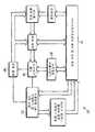
도 1은 본 발명의 일 실시예에 따른 적응적 유도성 안정기(adaptive inductive ballast)의 블록도.1 is a block diagram of an adaptive inductive ballast in accordance with one embodiment of the present invention.
도 2는 본 발명의 적응적 유도성 안정기를 포함하는 변경을 나타내기 위해 표시된 본 출원의 공진-탐색 안정기(resonance-seeking ballast)의 개략도.FIG. 2 is a schematic diagram of a resonance-seeking ballast of the present application indicated to show a modification involving an adaptive inductive ballast of the present invention. FIG.
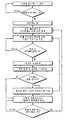
도 3은 적응적 유도성 안정기의 동작을 나타내는 흐름도.3 is a flow diagram illustrating operation of an adaptive inductive ballast.
도 4는 RF 통신 및 위상 제어를 포함하는 대체 실시예의 블록도.4 is a block diagram of an alternative embodiment that includes RF communication and phase control.
도 5는 통신 기능을 포함하는 적응적 유도성 안정기의 동작을 나타내는 흐름도.5 is a flow diagram illustrating operation of an adaptive inductive ballast that includes a communication function.
도 6은 원격 장치 및 워크스테이션에 접속된 비접촉 에너지 전송 시스템을 나타낸 도면.6 illustrates a contactless energy transfer system connected to a remote device and a workstation.
도 7은 통신 기능을 구비한 적응적 비접촉 에너지 전송 시스템에 대한 블록도.7 is a block diagram of an adaptive contactless energy transfer system with communication capabilities.
도 8은 통신 기능을 구비한 원격 장치의 블록도.8 is a block diagram of a remote device having a communication function.
도 9는 적응적 비접촉 에너지 전송 시스템의 동작을 나타내는 흐름도.9 is a flow diagram illustrating operation of an adaptive contactless energy transfer system.
도 10은 통신 기능을 구비한 비접촉 전력 공급기에 의해 전력이 공급되는 원격 장치들의 예시적인 목록.10 is an exemplary list of remote devices powered by a contactless power supply with communication capabilities.
설명을 위하여, 본 발명은 공진-탐색 안정기(resonance-seeking ballast), 특히 발명의 명칭이 "Inductively Coupled Ballast Circuit"이며 전체가 본 명세서에 참조로서 포함되는 미국 특허 출원 제10/246,155호에 개시된 유도성 안정기(inductive ballast)와 관련하여 기술된다. 그러나, 본 발명은 다른 유도성 안정기 회로용으로도 매우 적합하다.For illustrative purposes, the present invention relates to a resonance-seeking ballast, particularly the induction disclosed in US Patent Application No. 10 / 246,155, which is named "Inductively Coupled Ballast Circuit" and is incorporated herein by reference in its entirety. It is described in the context of an inductive ballast. However, the present invention is also very suitable for other inductive ballast circuits.
본 발명의 일 실시예에 따른 적응적 유도성 안정기(adaptive inductive ballast; 10)의 일반적인 구성을 나타내는 블록도는 도 1에 도시되어 있다. 도시된 바와 같이, 적응적 유도성 안정기(10)는 일반적으로 회로의 동작을 제어하는 마 이크로프로세서(12), 자기장을 생성하는 멀티-탭 프라이머리(multi-tap primary; 14), 프라이머리(14)에 인가되는 신호를 생성하는 파형 형성기 및 드라이브 부회로(wave shaper and drive subcircuit; 16), 프라이머리(14)에 인가된 신호를 모니터링하고 대응하는 피드백을 마이크로프로세서(12)에 제공하는 전류 감지 부회로(current sense subcircuit; 18), 파형 형성기 및 드라이브 부회로(16)에서의 커패시턴스 값을 조절하는 커패시턴스 스위치(20) 및 멀티-탭 프라이머리(14)의 인덕턴스를 조절하는 인덕턴스 스위치(22)를 포함한다. 마이크로프로세서는 다수의 공급자에 의해 널리 이용될 수 있는 종래의 마이크로프로세서이다.A block diagram illustrating a general configuration of an adaptive
커패시턴스 스위치(20)는 일반적으로 두 개의 뱅크(bank)의 커패시터들과, 두 개의 커패시터 뱅크들의 값들을 제어하기 위해 마이크로프로세서(12)에 의해 선택적으로 가동될 수 있는 트랜지스터와 같은 복수의 스위치를 포함한다. 각각의 뱅크 내의 커패시터들은 가능한 커패시턴스 값들의 원하는 범위 및 분포에 따라 직렬 또는 병렬로 배치될 수 있다. 커패시터들의 제1 뱅크는 커패시터(271)를 대체한다. 마찬가지로, 커패시터들의 제2 뱅크는 본 명세서에서 도시된 기존의 공진-탐색 안정기의 커패시터(272)를 대체한다. 사실상, 커패시턴스 스위치(20)는 기존의 공진-탐색 안정기로부터의 커패시터들(271 및 272)을, 마이크로프로세서(12)에 의해 값들이 제어되는 가변 커패시터들이 되게 한다. 대안적으로, 설명된 커패시턴스 스위치(20)는 가변 커패시턴스를 제공할 수 있는 다른 회로에 의해 대체될 수 있다.
인덕턴스 스위치(22)는 일반적으로 멀티-탭 프라이머리(14)와, 프라이머리 (14)의 인덕턴스의 값들을 제어하기 위해 마이크로프로세서(12)에 의해 선택적으로 가동될 수 있는 트랜지스터와 같은 복수의 스위치를 포함한다. 멀티-탭 프라이머리(14)는 기존의 공진-탐색 안정기의 프라이머리(270)를 대체한다. 사실상, 인덕턴스 스위치(22)는, 프라이머리(14)에서의 권선을 변경시킴으로써, 기존의 공진-탐색 안정기로부터의 프라이머리(270)를 마이크로프로세서(12)에 의해 값이 제어되는 가변 인덕턴스 코일이 되게 한다. 대안적으로, 설명된 인덕턴스 스위치(22)는 가변 인덕턴스를 제공할 수 있는 다른 회로에 의해 대체될 수 있다.
일반적인 동작에서, 마이크로프로세서(12)는, 전류 감지 부회로(18)로부터 프라이머리(14)에 인가된 전류를 나타내는 입력을 수신하도록 프로그래밍된다. 마이크로프로세서(12)는, 커패시턴스 스위치(20) 및 인덕턴스 스위치(22)를 개별적으로 조절하여 회로에 대해 이용가능한 커패시턴스 값들 및 인덕턴스 값들의 범위에 걸쳐 순환하도록 프로그래밍된다. 마이크로프로세서(12)는 어느 값들이 프라이머리(14)에 최적의 전류를 공급하는지를 결정하기 위해 커패시턴스 및 인덕턴스 값들을 조절하면서, 전류 감지 회로(18)로부터의 입력을 계속적으로 모니터링한다. 그 후, 마이크로프로세서(12)는 적응적 안정기를 최적의 설정으로 고정시킨다.In normal operation,
종래의 특허 출원의 공진-탐색 유도성 안정기를 적응적 유도성 안정기 회로(10)의 일 실시예로 적응시키기 위해 요청되는 변경들의 일부가 도 2의 개략도에 도시되어 있다.Some of the changes required to adapt the resonant-search inductive ballast of the prior patent application to one embodiment of the adaptive
기존의 공진-탐색 안정기는 미국 특허 출원 제10/246,155호에 보다 구체적으로 기술되어 있지만, 이 회로를 개괄하는 것이 본 발명을 더욱 완전하게 이해하는 데 도움이 될 수도 있다. 안정기 피드백 회로는 포인트 A에서 접속되고, 제어 회로는 포인트 B에서 접속된다. 오실레이터(oscillator; 144)는 드라이브(146)를 통해 하프 브리지 인버터(half bridge inverter; 148)에게 교류 신호를 제공한다. 하프 브리지 인버터는 탱크 회로(tank circuit; 150)에 전원을 공급한다. 전류 감지 회로(218)는 오실레이터(144)에게 피드백을 제공한다. 피드백 회로, 제어 회로, 오실레이터, 하프 브리지 인버터, 드라이브 및 전류 감지 회로(218)뿐만 아니라 그 밖의 지원 회로(supporting circuitry)에 대해서는 상술한 특허 출원에 보다 상세하게 기술되어 있다.Existing resonant-search ballasts are described in more detail in US patent application Ser. No. 10 / 246,155, but an overview of this circuit may help a more complete understanding of the present invention. The ballast feedback circuit is connected at point A, and the control circuit is connected at
도 2에서, 위상 지연은 E에서 삽입될 수 있으며, 지연 라인(delay line)으로서 제어될 수 있다. 이러한 지연은 위상을 조절하고 2차 진폭(secondary amplitude)을 제어하기 위해 사용될 수 있다. F에서는, 스위치 커패시턴스가 조절 가능한 1차 인덕턴스(primary inductance)에 기초하여 공진 주파수를 조절할 수 있다. 단순한 트랜지스터들이 커패시턴스를 스위칭시키기 위해 사용될 수 있다. 커패시턴스는, 1차 인덕터가 매치 부하(match load)에 대해 변하는 때에 변경된다. G에서는, 1차 인덕턴스가 2차 회로(secondary circuit)에 의해 요청되는 전력을 조절하기 위해 스위칭될 수 있다. RFID 또는 직접 통신은 필요한 부하를 지시할 수 있다. 제어 프로세서는 그러한 부하 정보를 이용하여, 요청되는 전력을 공급하기 위해 필요한 대로 인덕턴스를 조절할 수 있다. 인덕턴스는 마이크로프로세서에 의해 제어되는 1차 인덕터로부터의 다수의 탭 및 트랜지스터들을 이용하여 스위칭될 수 있다.In Figure 2, the phase delay can be inserted at E and can be controlled as a delay line. This delay can be used to adjust the phase and control the secondary amplitude. At F, the resonant frequency can be adjusted based on the primary inductance, where the switch capacitance is adjustable. Simple transistors can be used to switch capacitance. The capacitance is changed when the primary inductor changes with respect to the match load. At G, the primary inductance can be switched to regulate the power required by the secondary circuit. RFID or direct communication may indicate the required load. The control processor can use such load information to adjust the inductance as needed to supply the requested power. Inductance can be switched using multiple taps and transistors from a primary inductor controlled by a microprocessor.
적응적 유도성 안정기 회로의 동작 시퀀스가 도 3과 관련하여 더욱 상세하게 기술된다. 동작 시에, 설명된 시스템은, 전력을 프라이머리(14)에 인가하기 전에 부하가 존재하는지를 결정할 때까지 대기한다. 이는 전력의 낭비를 막을 것인 바, 유도적으로 전원이 인가된 각각의 장치에게 프라이머리에 인접한 리드 스위치(reed switch)를 가동시키는 자석을 제공함으로써 행해질 수 있다. 대안적으로, 유도적으로 전원이 인가된 장치가 존재하는 경우 사용자가 전력 공급에 관여할 수 있도록 하기 위해, 사용자-가동 스위치(user-actuated switch)(도시되지 않음)가 제공될 수 있다. 다른 대안으로서, 유도적으로 전원이 인가된 장치는 자신의 존재를 알리기 위해, 프라이머리 근방에 배치되는 경우 기계적으로 스위치를 가동시키도록 구성될 수 있다. 또 다른 대안으로서, 스위칭 메커니즘을 제거하고, 안정기 회로가 부하의 존재와 무관하게 프라이머리(14)에 전력을 공급할 수 있다.The operating sequence of the adaptive inductive ballast circuit is described in more detail with respect to FIG. 3. In operation, the described system waits to determine if a load is present before applying power to the primary 14. This may be done by providing a magnet that activates a reed switch adjacent to the primary to each device that is inductively powered, which will prevent waste of power. Alternatively, a user-actuated switch (not shown) may be provided to enable the user to engage in power supply when there is an inductively powered device. As another alternative, the inductively powered device may be configured to mechanically activate the switch when placed near the primary to indicate its presence. As another alternative, the switching mechanism can be eliminated, and the ballast circuit can power the primary 14 regardless of the presence of the load.
전원 공급 회로가 가동되면, 회로는 주파수를 조정해서 프라이머리에 적용되는 전류를 최적화한다. 초기 커패시턴스 및 인덕턴스 값에서 적절한 동작 주파수가 결정된 이후에, 마이크로프로세서는 안정기 회로(ballast circuit)를 동작 주파수로 락킹(locking)하고 이어서 다중 탭 프라이머리(multi-tap primary)를 통해서 이용가능한 인덕턴스 값의 범위를 통해 순환하기 시작한다. 인덕턴스 값에서의 각 변화 이후에, 마이크로프로세서는 동작 주파수를 언락킹(unlocking)하고 안정기 회로가 공진(resonance)을 찾도록 하며, 공진은 프라이머리에 최적의 전류를 제공하는 주파수에서 안정된다. 마이크로프로세서는, 어떤 값이 프라이머리에 최적의 전류를 제공하는지를 결정할 때까지 이용가능한 인덕턴스 값을 통해 순환을 계속한 다. 일 실시예에서, 점진적인 스캐닝 프로세스(progressive scanning process)가 적절한 인덕턴스 값을 결정하기 위해 사용된다. 이것은 가장 작은 인덕턴스 값에서 스캐닝 프로세스를 시작하고, 인덕턴스 값에 있어서의 변화가 프라이머리에 적용되는 전류에 있어서의 감소를 야기할 때까지 인덕턴스 값을 단계적으로 증가시킴으로써 달성된다. 이어서 마이크로프로세서는 인덕턴스 값을 한 단계 내리고, 여기서 최대 전류가 달성된다. 대안적으로, 스캐닝 프로세스는 최고의 인덕턴스 값에서 시작해서, 인덕턴스 값에 있어서의 변화가 프라이머리에 적용되는 전류에 있어서의 감소를 야기할 때까지 인덕턴스 값을 순차적으로 한 단계씩 낮추어 갈 수 있다. 이어서 마이크로프로세서는 인덕턴스 값을 한 단계 올리고, 여기서 최대 전류가 달성된다. 또 다른 대안으로서, 마이크로프로세서는 각각의 인덕턴스 값을 단계적으로 진행해서 대응하는 전류를 결정하고, 각각의 값을 지나간 후에 프라이머리에게 가장 큰 전류를 제공하는 인덕턴스 값으로 복귀한다.When the power supply circuit is activated, the circuit adjusts the frequency to optimize the current applied to the primary. After the appropriate operating frequency has been determined from the initial capacitance and inductance values, the microprocessor locks the ballast circuit to the operating frequency and then of the inductance value available through a multi-tap primary. It begins to cycle through the range. After each change in inductance value, the microprocessor unlocks the operating frequency and causes the ballast circuit to find resonance, which settles at the frequency that provides the optimum current to the primary. The microprocessor continues to cycle through the available inductance values until it determines which value provides the optimum current for the primary. In one embodiment, a progressive scanning process is used to determine the appropriate inductance value. This is accomplished by starting the scanning process at the smallest inductance value and incrementally increasing the inductance value until a change in inductance value causes a decrease in the current applied to the primary. The microprocessor then lowers the inductance value one step, where the maximum current is achieved. Alternatively, the scanning process may start at the highest inductance value and sequentially step down the inductance value until a change in inductance value causes a decrease in the current applied to the primary. The microprocessor then raises the inductance value one step, where the maximum current is achieved. As another alternative, the microprocessor steps through each inductance value to determine the corresponding current, and after each value returns to the inductance value that provides the largest current to the primary.
적절한 인덕턴스 값이 결정된 이후에, 마이크로프로세서는 회로를 결정된 값에서 락킹하고 커패시턴스 값을 순회하기 시작한다. 일 실시예에서, 마이크로프로세서는 점진적인 스캐닝 기법을 사용하여 프라이머리에게 가장 큰 전류를 제공하는 커패시턴스를 결정한다. 스캐닝 프로세스는, 인덕턴스 값에 대한 스캐닝 프로세스에 대하여 전술한 바와 같이, 가장 낮은 커패시턴스 값으로부터 상방 진행할 수 있거나 최대 커패시턴스 값으로부터 하방 진행할 수 있다. 점진적인 스캐닝 프로세스에 대한 대안으로서, 마이크로프로세서는 각각의 커패시턴스 값을 단계적으로 진행하여서 대응하는 전류를 결정하고, 각각의 값을 지나간 이후에, 프라이머리에 최 대 전류를 제공하는 커패시턴스 값으로 복귀한다.After the appropriate inductance value has been determined, the microprocessor locks the circuit at the determined value and begins to traverse the capacitance value. In one embodiment, the microprocessor uses a gradual scanning technique to determine the capacitance that provides the largest current to the primary. The scanning process may proceed upward from the lowest capacitance value or proceed downward from the maximum capacitance value, as described above with respect to the scanning process for inductance values. As an alternative to the gradual scanning process, the microprocessor steps through each capacitance value to determine the corresponding current, and after each value, returns to the capacitance value that provides the maximum current to the primary.
본 실시예에서, 일단 적절한 인덕턴스 값이 결정되면 안정기 회로의 주파수는 변화하도록 허용되지 않는다. 대안적으로, 마이크로프로세서는 커패시턴스 값에서의 각 변화 이후에 안정기 회로가 공진을 찾도록 프로그램된다.In this embodiment, the frequency of the ballast circuit is not allowed to change once an appropriate inductance value is determined. Alternatively, the microprocessor is programmed so that the ballast circuit finds resonance after each change in capacitance value.
대안적인 실시예에서, 마이크로프로세서는, 전원 공급 회로의 커패시턴스 값만 또는 인덕턴스 값만의 조정을 제공하도록 프로그램될 수 있다. 전자의 대안에서는, 다중 탭 프라이머리가 종래의 단일 탭 프라이머리로 대체될 수 있고, 인덕턴스 스위치가 제거될 수 있다. 후자의 대안에서는, 커패시터 뱅크가 단일 집합의 커패시터로 대체될 수 있고 커패시턴스 스위치는 제거될 수 있다. 그 밖의 대안적인 실시예에서, 마이크로프로세서는 인덕턴스를 조정하기 전에 커패시턴스를 조정하도록 프로그램될 수 있다.In an alternative embodiment, the microprocessor may be programmed to provide adjustment of only the capacitance value or only the inductance value of the power supply circuit. In the former alternative, multi-tap primary can be replaced with conventional single tap primary and inductance switches can be eliminated. In the latter alternative, the capacitor bank can be replaced with a single set of capacitors and the capacitance switch can be removed. In other alternative embodiments, the microprocessor may be programmed to adjust capacitance before adjusting inductance.
전술한 바와 같이, 본 발명은 공진 탐색 안정기와 함께 사용되는 것에 제한되는 것은 아니다. 다른 애플리케이션에서는, 전류 센서가 안정기에 통합되어서 프라이머리에 적용되는 전류를 나타내는 마이크로프로세서에 입력을 제공할 수 있다. 공진 탐색 안정기가 없는 동작에서, 마이크로프로세서는 다양한 커패시턴스 및 인덕턴스 값을 별도로 순회해서 프라이머리에 최적의 전력을 제공하는 값을 결정할 것이다.As noted above, the present invention is not limited to use with a resonant seek ballast. In other applications, a current sensor can be integrated into the ballast to provide an input to the microprocessor that represents the current applied to the primary. In operation without resonant seek ballast, the microprocessor will traverse the various capacitance and inductance values separately to determine the value that provides optimum power to the primary.
또 다른 대안적인 실시예에서, 적응적 유도성 안정기(10)는 위상 안정기(10)가 위상을 조절하고 2차 진폭을 제어하도록 하는 지연 회로(도시되지 않음)를 포함할 수 있다. 위상 지연 회로는, 동작 증폭기(21)에 이어지는 파형 형성기 및 드라 이브 회로(16)에 연결되는 지연 라인 또는 디지털 신호 프로세서(DSP)를 포함할 수 있다.In another alternative embodiment, adaptive
본 발명의 그 밖의 대안적인 실시예가 도 4 내지 도 5와 함께 설명된다. 본 실시예에서, 적응적 유도성 안정기(10') 및 유도적으로 전원 공급되는 장치는 예컨대 종래의 RF 통신 또는 직접 통신을 사용하여 통신할 수 있다.Other alternative embodiments of the present invention are described in conjunction with FIGS. 4-5. In this embodiment, the adaptive inductive ballast 10 'and the inductively powered device can communicate using, for example, conventional RF communication or direct communication.
도 4는 적응적 유도성 안정기(10')의 일반적인 컴포넌트를 도시하는 블록도이다. 적응적 유도성 안정기(10')는 스위칭된 1차 인덕턴스 및 1차 코일(22')과는 별도인 통신 코일(도시되지 않음)을 포함한다. 통신 코일은 프라이머리의 일부일 수 있다. 통신 코일은 마이크로프로세서(12')에 연결되고, 마이크로프로세서는 유도적으로 전원 공급된 장치로부터 정보를 수신하고 상기 정보에 기초하여 적응적 유도성 안정기(10')의 동작에 영향을 미치도록 프로그램된다. 또한, 유도적으로 전원 공급된 장치는 프라이머리로부터 전원을 받는 세컨더리(secondary)와는 별도로 되거나 또는 그와 통합될 수 있는 통신 코일을 포함한다. 유도적으로 전원 공급된 부하 및 적응적 유도성 전력 공급기(10')는 예컨대 표준 통신 회로 및 표준 통신 프로토콜을 사용하여서 종래의 통신 기법 및 장치를 이용하여 통신한다.4 is a block diagram illustrating the general components of an adaptive inductive ballast 10 '. Adaptive inductive ballast 10 'includes a communication coil (not shown) separate from the switched primary inductance and primary coil 22'. The communication coil may be part of the primary. The communication coil is coupled to the microprocessor 12 ', which is programmed to receive information from the inductively powered device and to influence the operation of the adaptive inductive ballast 10' based on the information. do. The inductively powered device also includes a communication coil that can be separate from or integrated with a secondary powered from the primary. The inductively powered load and the adaptive inductive power supply 10 'communicate using conventional communication techniques and apparatus, for example using standard communication circuits and standard communication protocols.
적응적 안정기(10')의 동작은 일반적으로 전술한 안정기(10)의 동작과 동일하나, 이하에 설명되는 것만 다르다. 안정기(10')의 동작의 일반적인 단계를 도시하는 흐름도가 도 5에 도시되어 있다. 통신 능력의 사용을 통하여, 유도적으로 전원공급된 장치는 부하의 와트 수(wattage)와 같은 부하 정보를 적응적 유도성 안정기(10')로 전달한다. 적응적 유도성 안정기(10')는 이러한 정보를 적절한 커패시 턴스 및 인덕턴스 값을 결정하는데 사용할 수 있다. 더욱 구체적으로, 이러한 정보는 스위칭된 1차 인덕턴스 및 1차 코일(22')의 프라이머리가 올바른 와트 수에서 동작하는 것을 보장하는데 사용된다. 그렇지 않으면, 스위칭된 1차 인덕턴스 및 1차 코일(22')의 스위칭된 1차 인덕턴스 및 커패시턴스 스위치(20')가 프라이머리의 와트 수를 조절하는데 사용될 수 있다. 이러한 실시예는, 소정의 애플리케이션에서, 전술한 적응적 유도성 안정기(10)에 대해 개선된 동작을 제공하는데 이는 적응적 유도성 안정기가 반드시 가능한 최고의 전류 값에서 동작하는 것이 아니기 때문이다. 그 대신에, 이러한 실시예는 프라이머리의 전력 출력을 유도적으로 전원 공급된 장치의 전력 요구 사항에 맞추며, 이는 최대 전력이 요구되지 않는 경우에 전력을 감소시키고 에너지를 절약할 수 있다는 것을 의미한다.The operation of the adaptive ballast 10 'is generally the same as the operation of the
도 1 내지 도 5의 전술한 시스템은 도 6 내지 도 9를 참조하여 더 개선되고 설명된다.The aforementioned system of FIGS. 1-5 is further refined and described with reference to FIGS. 6-9.
도 6은 본 발명의 일 실시예를 포함하는 적응적 비접촉 에너지 송신 시스템을 도시한다. 비접촉 전력 공급기(305)는 원격 장치(306)에 유도적으로 연결된다. 또한, 비접촉 전력 공급기(305)는 워크스테이션(307)에 연결된다. 네트워크(308)는 또한 워크스테이션(307)에 연결된다.6 illustrates an adaptive contactless energy transmission system incorporating one embodiment of the present invention. The
일 실시예에서, 비접촉 전력 공급기(305)는 워크스테이션(307) 및 원격 장치(306) 사이에 통신 링크를 설정하고 정보가 원격 장치(306)로 그리고 그로부터 송신되도록 한다. 원격 장치(306)가 PDA인 경우, PDA로부터의 정보가 워크스테이션과 교환될 수 있다. 예컨대, PDA는 충전하는 동안에 자동으로 달력 및 어드레스 목록을 동기화할 수 있다. 다른 예로서, 원격 장치(306)가 MP3 플레이어인 경우, MP3 플레이어가 충전되는 동안에 MP3 플레이어로 그리고 그로부터 노래가 다운로드될 수 있다.In one embodiment, the
도 7은 복수의 원격 장치와 통신하기 위한 통신 장치를 구비하는 적응적 비접촉 에너지 송신 시스템을 도시한다.7 illustrates an adaptive contactless energy transmission system having a communication device for communicating with a plurality of remote devices.
적응적 비접촉 에너지 송신 시스템은 비접촉 전원 공급 장치(305) 및 원격 장치(338, 340, 342)를 포함한다.The adaptive contactless energy transmission system includes a
잘 알려진 바와 같이, 전원(310)은 DC(직류 전류) 전력을 인버터(312)에 공급하는 DC 전원이다. 인버터(312)는 DC 전력을 AC(교류 전류) 전력으로 변환한다. 인버터(312)는 AC 전력을 탱크 회로(314)에 공급하는 AC 전원으로서 작동한다. 탱크 회로(314)는 공진 회로이다. 탱크 회로(314)는 원격 장치(338)의 2차 권선(316)에 유도적으로 연결된다.As is well known, the
원격 장치들(338, 340, 342)의 2차 권선은 코어(core)를 갖지 않는다. 파선(320)은 원격 장치들(338, 340, 342) 및 전력 공급기(305) 간의 에어 갭(air gap)을 나타낸다.The secondary winding of the
회로 센서(324)는 탱크 센서(314)의 출력에 연결된다. 또한, 회로 센서(324)는 제어기(326)에 연결된다. 회로 센서(324)는 전력 공급기의 동작 파라미터에 관한 정보를 제공한다. 예컨대, 회로 센서는 전류 센서일 수 있고 탱크 회로(314)의 위상, 주파수 및 진폭에 관한 정보를 제공한다.The
제어기(326)는 인텔 8051 또는 모토롤라 6811 또는 그러한 마이크로컨트롤러 의 다수의 변종 중 임의의 것과 같이 이하에 설명되는 기능을 수행하도록 프로그램된 다수의 일반적으로 이용가능한 마이크로컨트롤러 중 하나일 수 있다. 제어기(326)는 칩 상에 ROM 및 RAM을 가질 수 있다. 제어기(326)는 적응적 유도성 전력 공급기 내에서 다양한 기능을 제어하기 위한 일련의 아날로그 및 디지털 출력을 가질 수 있다.The
제어기(326)는 메모리(327)에 연결된다. 또한, 제어기(326)는 드라이브 회로(328)에 연결된다. 드라이브 회로(328)는 인버터(312)의 동작을 규제한다. 드라이브 회로(328)는 인버터(321)의 주파수 및 타이밍을 규제한다. 또한, 제어기(326)는 전원(310)에 연결된다. 제어기(326)는 전원(310)의 레일 전압을 조작할 수 있다. 잘 알려진 바와 같이, 전원(310)의 레일 전압을 변경함으로써, 인버터(312)의 출력의 진폭도 또한 변경된다.
마지막으로, 제어기(326)는 탱크 회로(314)의 가변 인덕터(330) 및 가변 커패시터(332)에 연결된다. 제어기(326)는 가변 인덕터의 인덕턴스 또는 가변 커패시터(332)의 커패시턴스를 수정할 수 있다. 가변 인덕터의 인덕턴스 및 가변 커패시터(332)의 커패시턴스를 수정함으로써, 탱크 회로(314)의 공진 주파수가 변경 가능하다.Finally, the
탱크 회로(314)는 제1 공진 주파수 및 제2 공진 주파수를 가질 수 있다. 또한, 탱크 회로(314)는 몇 개의 공진 주파수를 가질 수 있다. 본 명세서에서 사용되는 바와 같이, "공진 주파수"라는 용어는 탱크 회로(314)가 공진하는 주파수 대역을 지칭한다. 잘 알려진 바와 같이, 탱크 회로는 공진 주파수를 가질 것이나, 주파수 대역 내에서 계속해서 공진할 것이다. 탱크 회로(314)는 가변 임피던스를 갖는 적어도 하나의 가변 임피던스 소자를 구비한다. 가변 임피던스를 변동함으로써, 탱크 회로의 공진 주파수는 변동될 것이다. 가변 임피던스 소자는 가변 인덕터(330) 또는 가변 커패시터(332) 또는 둘 다 일수 있다.The
가변 인덕터(330)는 사이리스터 제어 가변 인덕터(thyrister controlled variable inductor), 압축가능 가변 인덕터(compressible variable inductor), 평행 적층 코어 가변 인덕터(parallel laminated core variable inductor), 선택 고정된 인덕터를 탱크 회로(314)에 위치시킬 수 있는 일련의 인덕터 및 스위치 또는 임의의 기타 제어가능한 가변 인덕터일 수 있다. 가변 커패시터는 스위칭된 커패시터 배열, 선택 고정된 커패시터를 탱크 회로(314)에 위치시킬 수 있는 일련의 커패시터 및 스위치 또는 임의의 기타 제어가능한 가변 커패시터일 수 있다.The
또한, 탱크 회로(314)는 1차 권선(334)을 포함할 수 있다. 1차 권선(334) 및 가변 인덕터(330)는 별도로 도시된다. 대안적으로, 1차 권선(334) 및 가변 인덕터(330)는 단일 소자로 결합될 수 있다. 탱크 회로(314)는 일련의 공진 탱크 회로로서 도시된다. 또한, 병렬 공진 탱크 회로가 사용될 수 있다.
또한, 전력 공급기 송수신기(336)가 제어기에 연결된다. 전력 공급기 송수신기(336)는 쌍방향 통신을 가능하게 하는 장치가 아닌 정보를 수신하기 위한 단순한 수신기일 수 있다. 전력 공급기 송수신기(336)는 다양한 원격 장치(338, 340, 342)와 통신할 수 있다. 분명하게, 세 개 이상 또는 그 이하의 장치가 시스템에 사용될 수 있다.Also, a power supply transceiver 336 is connected to the controller. The power supply transceiver 336 may be a simple receiver for receiving information that is not a device that enables two-way communication. The power supply transceiver 336 can communicate with various
본 실시예에서, 비접촉 전력 공급기(305)는 또한 워크스테이션(307)과의 연결을 위한 통신 인터페이스(311)를 갖는다. 통신 인터페이스(311)는 USB, 파이어와이어(firewire) 또는 RS-232와 같은 공지의 또는 독점의 임의의 다수의 인터페이스일 수 있다. 워크스테이션(307)은 네트워크(308)에 연결된다. 네트워크(308)는 LAN(local area network) 또는 인터넷일 수 있다.In this embodiment, the
또한, 비접촉 전력 공급기(305)는 통신 제어기(313)를 가질 수 있다. 통신 제어기(313)는 통신 인터페이스(311) 및 전력 공급기 송수신기(336)를 통해서 데이터 입력 및 출력을 관리할 수 있다. 통신 제어기(313)는 관리 정보 수집뿐만 아니라 코드 변환, 프로토콜 변환, 버퍼링, 데이터 압축, 오류 체킹, 동기화 및 경로 선택과 같은 필요한 제어 기능을 수행한다. 통신 제어기(313)는 원격 장치(338, 340, 342) 및 워크스테이션(307) 또는 네트워크(308) 내의 임의의 다른 장치 간에 통신 세션을 설정한다. 통신 제어기(313)는 전단(front end) 프로세서일 수 있다. 제어기(326)의 능력에 따라서, 통신 제어기(313)는 제어기(326) 내에서 실행되는 소프트웨어 모듈일 수 있다.In addition, the
도 8은 원격 장치(338)의 블록도를 도시한다. 원격 장치(338)는 또한 원격 장치(340, 342)의 예시이다. 원격 장치(338)는 부하(350)를 포함한다. 부하(350)는 가변 세컨더리(variable secondary; 353)로부터 전력을 수신한다. 부하(350)는 충전 가능 전지 또는 임의의 다른 종류의 부하일 수 있다.8 shows a block diagram of a
가변 세컨더리(353)는 코어리스(coreless)인 것이 바람직하며, 가변 세컨더리가 더 넓은 범위의 주파수에서 동작하도록 한다. 가변 세컨더리(353)는 가변 인덕터로서 도시되지만, 다른 종류의 장치가 가변 인덕터를 대체해서 사용될 수 있 다.The variable secondary 353 is preferably coreless and allows the variable secondary to operate at a wider range of frequencies. Although variable secondary 353 is shown as a variable inductor, other types of devices may be used in place of the variable inductor.
원격 장치 제어기(352)는 가변 세컨더리(253)의 인덕턴스 및 부하(350)의 동작을 제어한다. 예컨대, 원격 장치 제어기(352)는 가변 세컨더리(353)의 인덕턴스를 변경할 수 있거나 또는 부하(350)를 켜거나 끌 수 있다. 제어기(326)와 유사하게, 원격 장치 제어기(352)는, 인텔 8051 또는 모토롤라 6811 또는 임의의 다수의 그러한 마이크로컨트롤러의 변종과 같은 본 명세서에 설명된 기능을 수행하도록 프로그래밍된 다수의 공동으로 이용가능한 마이크로컨트롤러 중 임의의 하나일 수 있다. 제어기(352)는 칩 상에 ROM 및 RAM을 구비할 수 있다. 또한, 제어기(352)는 적응적 유도성 전력 공급기 내의 다양한 기능을 제어하기 위한 일련의 아날로그 및 디지털 출력을 가질 수 있다.The
메모리(354)는 다른 것들 중에서, 장치 ID 번호 및 원격 장치(338)에 관한 전력 정보를 포함한다. 전력 정보는 원격 장치(338)에 대한 전압, 전류 및 전력 소비 정보를 포함할 수 있다. 부하(350)가 충전가능 전지인 경우, 메모리(354)는 방전율 및 충전율을 포함할 수 있다.
또한, 원격 장치(338)는 원격 송수신기(356)를 포함할 수 있다. 원격 송수신기(356)는 전력 공급기 송수신기(336)로 그리고 그로부터 정보를 수신 및 송신한다. 원격 송수신기(356) 및 전력 공급기 송수신기(336)는 WIFI, 적외선, 블루투스 또는 셀룰러와 같은 무수히 많은 상이한 방식으로 연결될 수 있다. 또한, 송수신기는 프라이머리 또는 세컨더리 상에 추가적인 코일에 의해서 통신할 수 있다. 또는, 전력은 전력 공급기(305)에 의해서 원격 장치(338, 340, 342)로 전달되기 때문 에, 다수의 상이한 전력선 통신 시스템 중 임의의 것에 의할 수 있다.The
대안적으로, 원격 송수신기(356)는 송수신기(336)에 정보를 송신하기 위한 단순한 무선 송신기일 수 있다. 예컨대, 원격 송수신기(356)는 RFID(Radio Frequency Identification) 태그(tag)일 수 있다.Alternatively,
프로세서(357)는 원격 장치(338)의 기능적 컴포넌트를 나타낸다. 예컨대, 원격 장치(338)가 디지털 카메라인 경우, 프로세서(357)는 디지털 카메라 내의 마이크로 프로세서일 수 있다. 원격 장치(357)가 MP3 플레이어인 경우, 프로세서(357)는 디지털 프로세서 또는 마이크로프로세서 및 MP3 파일을 음향으로 변환하기 위한 회로일 수 있다. 원격 장치(338)가 PDA인 경우, 프로세서(357)는 마이크로프로세서 및 PDA의 기능을 제공하는 관련 회로이다. 프로세서(357)는 메모리(354)에 액세스할 수 있다.
프로세서(357)는 또한 2차 장치 송수신기(356)에 연결된다. 따라서, 프로세서(357)는 2차 장치 송수신기(356)를 통하여 비접촉 전력 공급기(305)와 통신할 수 있으며, 이에 의하여 워크스테이션과 같은, 전력 공급기(305)에 접속된 임의의 다른 장치들과 통신할 수 있다.
통신 인터페이스(311)의 존재로 인하여, 원격 장치(338)는 워크스테이션(307) 또는 네트워크(308)로 통신할 수 있다. 원격 장치(338)와 워크스테이션(307) 간의 통신을 가능하게 하기 위하여, 제어기(326)는 송수신기(336)를 경유하여 원격 장치(338)로 통신 링크를 설정할 것이다.Due to the presence of the
도 9는 통신 능력을 가진 적응적 비접촉 에너지 전송 시스템의 동작을 도시 한다.9 illustrates the operation of an adaptive contactless energy transfer system with communication capabilities.
비접촉 전력 공급기(305)는 시작한(단계 400) 후에, 송수신기(336)를 통하여 모든 원격 장치에 폴링한다(단계 402). 단계(402)는 지속될 수 있으며, 단계(404)로의 진행은 원격 장치가 존재하는 경우에만 발생한다. 대안으로, 이후의 단계들은 폴링이 반복되기 이전에 수행될 수 있으며, 동작들은 공 집합(null set)을 참조하여 수행될 것이다. 임의의 원격 장치가 존재하는 경우, 원격 장치로부터 전력 사용량 정보를 수신한다(단계 404).The
전력 사용량 정보는 원격 장치(338)에 대한 전압, 전류 및 전력 요구 사항에 관한 실제 정보를 포함할 수 있다. 대안으로, 전력 사용량 정보는 간단하게 원격 장치(338)에 대한 ID 번호일 수 있다. 그러한 경우, 제어기(326)는 ID 번호를 수신하고, 메모리(327) 내에 포함된 표로부터 원격 장치(338)에 대한 전력 요구 사항을 탐색할 것이다.Power usage information may include actual information regarding voltage, current, and power requirements for
모든 장치들이 폴링되고, 각 장치에 대한 전력 정보가 수신된 후에, 비접촉 전력 공급기(305)는 임의의 장치가 더 이상 존재하지 않는지 여부를 판정한다. 그러한 경우, 원격 장치 목록은 갱신된다(단계 408).After all devices are polled and power information for each device is received, the
제어기(326)에 의해 유지되는 원격 장치 목록은 도 10에 도시되어 있다. 원격 장치 목록은 원격 장치(338, 340, 342) 각각에 대하여 장치 ID, 전압, 전류 및 상태를 포함할 수 있다. 장치 번호는 제어기(326)에 의해 할당된다. 장치 ID는 원격 장치들(338, 340, 342)로부터 수신된다. 두 개의 원격 장치가 동일한 유형인 경우, 장치 ID는 동일할 수 있다. 전압 및 전류는, 장치에 전력을 공급하기 위하 여 요구되는 전압 또는 전류의 양이다. 전압 및 전류는, 원격 장치들(338, 340, 342)에 의하여 따로 전송될 수도 있으며, 또는 메모리(327)에 유지되는 원격 장치들의 데이터베이스에 대한 키로서 장치 ID를 사용함으로써 얻을 수도 있다. 상태는 장치의 현재 상태이다. 예를 들어, 장치 상태는 '온(on)', '오프(off)', '충전(charging)'일 수 있다.The list of remote devices maintained by the
다음으로, 비접촉 전력 공급기(305)는 임의의 장치의 상태가 변경되었는지 여부를 판정한다(단계 410). 예를 들어, 원격 장치(338)는 충전가능 전지를 가질 수 있다. 충전가능 전지가 완전히 충전된 경우, 원격 장치(338)는 더 이상 전력이 필요 없을 것이다. 따라서, 그 상태는 "충전"으로부터 "오프"로 변경될 것이다. 장치의 상태가 변경되는 경우, 원격 장치 목록은 갱신된다(단계 412).Next, the
그 후, 비접촉 전력 공급기(305)는 임의의 장치가 존재하는지 여부를 판정한다(단계 414). 존재하는 경우, 원격 장치 목록은 갱신된다(단계 416). 그 후, 원격 장치 목록은 검사된다(단계 418). 목록이 갱신되지 않은 경우, 시스템은 장치들을 다시 폴링하고, 프로세스는 재시작한다(단계 402).The
목록이 갱신된 경우, 원격 장치들에 의한 전력 사용량은 변경되었으며, 따라서 비접촉 전력 공급기(305)에 의해 공급되는 전력 또한 변경되어야 한다. 제어기(326)는 모든 원격 장치들의 전력 요구 사항을 판정하기 위하여 원격 장치를 사용한다. 그 후, 시스템이 모든 장치들에 전력을 충분하게 공급하도록 재구성될 수 있는지 여부를 판정한다.When the list is updated, the power usage by the remote devices has changed, so the power supplied by the
비접촉 전력 공급기(305)가 원격 장치들 모두에 전력을 공급할 수 있는 경우 에는, 제어기(326)는 인버터 주파수, 듀티 싸이클, 공진 주파수 및 레일 전압에 대한 설정들(settings)을 계산한다. 나아가, 제어기는 원격 장치들(338, 340, 342)의 2차 권선(353)의 가변 임피던스에 대한 최선의 설정을 결정한다(단계 422). 그 후, 인버터 주파수, 듀티 싸이클, 공진 주파수 및 레일 전압을 설정한다(단계 424). 또한, 원격 장치들(338, 340, 342)에게 2차 권선(353)의 가변 임피던스를 희망하는 레벨로 설정하도록 지시한다(단계 424).If the
반면에, 비접촉 전력 공급기(305)가 원격 장치들 모두에게 전력을 공급할 수 없는 경우에는, 제어기(326)는 전체 시스템에 대하여 최선의 가능한 전력 설정들을 결정한다(단계 426). 그 후, 원격 장치들(338, 340, 342) 중 하나 이상의 장치에게 전원을 끄거나 전력 소비를 변경하도록 지시할 수 있다. 제어기는 원격 장치들(338, 340, 342)의 2차 권선(353)의 가변 임피던스에 대한 최선의 설정을 결정한다(단계 428). 그 후, 시스템에 대한 인버터 주파수, 듀티 싸이클, 공진 주파수 및 레일 전압을 설정한다(단계 430). 제어기는 원격 장치들(338, 340, 342)에게 2차 권선(353)의 가변 임피던스를 희망하는 레벨로 설정하도록 지시한다. 그 후, 시스템은 장치들을 폴링하도록 복귀하고, 프로세스는 반복한다(단계 402).On the other hand, if the
상기 설명은 바람직한 실시예에 관한 것이다. 본 발명의 본질 및 더 넓은 양상들로부터 벗어나지 않은 채 다양한 교체 및 변경이 이루어질 수 있으며, 첨부된 청구범위 내에서 정의되는 바와 같은 본 발명은 균등론을 포함하는 특허법의 원칙에 따라 해석되어야 한다. 예를 들어, "한", "하나의", "그" 또는 "상기"를 사용하여 단수로 요소들을 청구하는 임의의 언급은 그 요소를 단수로 한정하는 것으 로 해석되어서는 안 된다.The above description relates to a preferred embodiment. Various changes and modifications may be made without departing from the spirit and broader aspects of the invention, and the invention as defined within the appended claims should be construed in accordance with the principles of patent law, including equivalents. For example, any statement claiming an element in the singular using “a”, “an”, “the” or “the above” should not be construed as limiting the element to singular.
Claims (55)
Translated fromKoreanApplications Claiming Priority (4)
| Application Number | Priority Date | Filing Date | Title |
|---|---|---|---|
| US44479403P | 2003-02-04 | 2003-02-04 | |
| US60/444,794 | 2003-02-04 | ||
| US10/689,148US7522878B2 (en) | 1999-06-21 | 2003-10-20 | Adaptive inductive power supply with communication |
| US10/689,148 | 2003-10-20 |
Related Child Applications (1)
| Application Number | Title | Priority Date | Filing Date |
|---|---|---|---|
| KR1020097015863ADivisionKR101108419B1 (en) | 2003-02-04 | 2004-01-22 | System and method for inductive power supply control using remote device power requirements |
Publications (2)
| Publication Number | Publication Date |
|---|---|
| KR20050105200A KR20050105200A (en) | 2005-11-03 |
| KR100996777B1true KR100996777B1 (en) | 2010-11-25 |
Family
ID=32871929
Family Applications (3)
| Application Number | Title | Priority Date | Filing Date |
|---|---|---|---|
| KR1020117009459AExpired - LifetimeKR101158224B1 (en) | 2003-02-04 | 2004-01-22 | System and method for inductive power supply control using remote device power requirements |
| KR1020057014353AExpired - LifetimeKR100996777B1 (en) | 2003-02-04 | 2004-01-22 | Adaptive Inductive Power Supply with Communication Function and Its Operation Method |
| KR1020097015863AExpired - LifetimeKR101108419B1 (en) | 2003-02-04 | 2004-01-22 | System and method for inductive power supply control using remote device power requirements |
Family Applications Before (1)
| Application Number | Title | Priority Date | Filing Date |
|---|---|---|---|
| KR1020117009459AExpired - LifetimeKR101158224B1 (en) | 2003-02-04 | 2004-01-22 | System and method for inductive power supply control using remote device power requirements |
Family Applications After (1)
| Application Number | Title | Priority Date | Filing Date |
|---|---|---|---|
| KR1020097015863AExpired - LifetimeKR101108419B1 (en) | 2003-02-04 | 2004-01-22 | System and method for inductive power supply control using remote device power requirements |
Country Status (12)
| Country | Link |
|---|---|
| US (15) | US7522878B2 (en) |
| EP (11) | EP2161807B1 (en) |
| JP (8) | JP2006517778A (en) |
| KR (3) | KR101158224B1 (en) |
| CN (4) | CN100511913C (en) |
| AT (1) | ATE476776T1 (en) |
| DE (1) | DE602004028439D1 (en) |
| ES (4) | ES2688067T3 (en) |
| MY (3) | MY144400A (en) |
| TR (2) | TR201809278T4 (en) |
| TW (1) | TW200425609A (en) |
| WO (1) | WO2004073166A2 (en) |
Families Citing this family (541)
| Publication number | Priority date | Publication date | Assignee | Title |
|---|---|---|---|---|
| US7212414B2 (en) | 1999-06-21 | 2007-05-01 | Access Business Group International, Llc | Adaptive inductive power supply |
| US7612528B2 (en)* | 1999-06-21 | 2009-11-03 | Access Business Group International Llc | Vehicle interface |
| US7522878B2 (en) | 1999-06-21 | 2009-04-21 | Access Business Group International Llc | Adaptive inductive power supply with communication |
| US7065658B1 (en) | 2001-05-18 | 2006-06-20 | Palm, Incorporated | Method and apparatus for synchronizing and recharging a connector-less portable computer system |
| US7811231B2 (en) | 2002-12-31 | 2010-10-12 | Abbott Diabetes Care Inc. | Continuous glucose monitoring system and methods of use |
| US7587287B2 (en)* | 2003-04-04 | 2009-09-08 | Abbott Diabetes Care Inc. | Method and system for transferring analyte test data |
| US7679407B2 (en)* | 2003-04-28 | 2010-03-16 | Abbott Diabetes Care Inc. | Method and apparatus for providing peak detection circuitry for data communication systems |
| US7722536B2 (en)* | 2003-07-15 | 2010-05-25 | Abbott Diabetes Care Inc. | Glucose measuring device integrated into a holster for a personal area network device |
| WO2005089103A2 (en)* | 2004-02-17 | 2005-09-29 | Therasense, Inc. | Method and system for providing data communication in continuous glucose monitoring and management system |
| US20050198245A1 (en)* | 2004-03-06 | 2005-09-08 | John Burgess | Intelligent modular remote server management system |
| EP1810185A4 (en) | 2004-06-04 | 2010-01-06 | Therasense Inc | Diabetes care host-client architecture and data management system |
| NZ535390A (en) | 2004-09-16 | 2007-10-26 | Auckland Uniservices Ltd | Inductively powered mobile sensor system |
| US9788771B2 (en) | 2006-10-23 | 2017-10-17 | Abbott Diabetes Care Inc. | Variable speed sensor insertion devices and methods of use |
| US8029441B2 (en) | 2006-02-28 | 2011-10-04 | Abbott Diabetes Care Inc. | Analyte sensor transmitter unit configuration for a data monitoring and management system |
| JP2006223008A (en)* | 2005-02-08 | 2006-08-24 | Hitachi Ltd | DC-DC converter |
| US7545272B2 (en) | 2005-02-08 | 2009-06-09 | Therasense, Inc. | RF tag on test strips, test strip vials and boxes |
| DE102005022352A1 (en)* | 2005-05-13 | 2006-11-23 | BSH Bosch und Siemens Hausgeräte GmbH | Energy transmission device |
| US7768408B2 (en) | 2005-05-17 | 2010-08-03 | Abbott Diabetes Care Inc. | Method and system for providing data management in data monitoring system |
| US7825543B2 (en)* | 2005-07-12 | 2010-11-02 | Massachusetts Institute Of Technology | Wireless energy transfer |
| CN101860089B (en) | 2005-07-12 | 2013-02-06 | 麻省理工学院 | wireless non-radiative energy transfer |
| KR100970047B1 (en)* | 2005-07-19 | 2010-07-16 | 올림푸스 메디칼 시스템즈 가부시키가이샤 | Medical instrument storage device |
| US20070042729A1 (en)* | 2005-08-16 | 2007-02-22 | Baaman David W | Inductive power supply, remote device powered by inductive power supply and method for operating same |
| US7756561B2 (en)* | 2005-09-30 | 2010-07-13 | Abbott Diabetes Care Inc. | Method and apparatus for providing rechargeable power in data monitoring and management systems |
| US7382636B2 (en)* | 2005-10-14 | 2008-06-03 | Access Business Group International Llc | System and method for powering a load |
| US7583190B2 (en)* | 2005-10-31 | 2009-09-01 | Abbott Diabetes Care Inc. | Method and apparatus for providing data communication in data monitoring and management systems |
| KR100737560B1 (en)* | 2005-11-14 | 2007-07-10 | 주식회사 팬택앤큐리텔 | Contactless battery charger |
| GB0525623D0 (en)* | 2005-12-16 | 2006-01-25 | Hill Nicholas P R | RFID reader |
| US7952322B2 (en) | 2006-01-31 | 2011-05-31 | Mojo Mobility, Inc. | Inductive power source and charging system |
| US11201500B2 (en) | 2006-01-31 | 2021-12-14 | Mojo Mobility, Inc. | Efficiencies and flexibilities in inductive (wireless) charging |
| US8169185B2 (en) | 2006-01-31 | 2012-05-01 | Mojo Mobility, Inc. | System and method for inductive charging of portable devices |
| US7989986B2 (en) | 2006-03-23 | 2011-08-02 | Access Business Group International Llc | Inductive power supply with device identification |
| US11245287B2 (en) | 2006-03-23 | 2022-02-08 | Philips Ip Ventures B.V. | Inductive power supply with device identification |
| US7355150B2 (en)* | 2006-03-23 | 2008-04-08 | Access Business Group International Llc | Food preparation system with inductive power |
| US7801582B2 (en) | 2006-03-31 | 2010-09-21 | Abbott Diabetes Care Inc. | Analyte monitoring and management system and methods therefor |
| US9675290B2 (en) | 2012-10-30 | 2017-06-13 | Abbott Diabetes Care Inc. | Sensitivity calibration of in vivo sensors used to measure analyte concentration |
| US8219173B2 (en) | 2008-09-30 | 2012-07-10 | Abbott Diabetes Care Inc. | Optimizing analyte sensor calibration |
| US7620438B2 (en) | 2006-03-31 | 2009-11-17 | Abbott Diabetes Care Inc. | Method and system for powering an electronic device |
| NZ547604A (en)* | 2006-05-30 | 2008-09-26 | John Talbot Boys | Inductive power transfer system pick-up circuit |
| US7948208B2 (en)* | 2006-06-01 | 2011-05-24 | Mojo Mobility, Inc. | Power source, charging system, and inductive receiver for mobile devices |
| US11329511B2 (en) | 2006-06-01 | 2022-05-10 | Mojo Mobility Inc. | Power source, charging system, and inductive receiver for mobile devices |
| US7826873B2 (en)* | 2006-06-08 | 2010-11-02 | Flextronics Ap, Llc | Contactless energy transmission converter |
| US9022293B2 (en) | 2006-08-31 | 2015-05-05 | Semiconductor Energy Laboratory Co., Ltd. | Semiconductor device and power receiving device |
| KR100836634B1 (en)* | 2006-10-24 | 2008-06-10 | 주식회사 한림포스텍 | Portable terminal using a contactless charger, a battery pack for charging and a contactless charger for wireless data communication and power transmission |
| US9591392B2 (en)* | 2006-11-06 | 2017-03-07 | Plantronics, Inc. | Headset-derived real-time presence and communication systems and methods |
| US8339096B2 (en)* | 2006-11-20 | 2012-12-25 | Semiconductor Energy Laboratory Co., Ltd. | Wireless power receiving device |
| TWI339471B (en)* | 2006-12-27 | 2011-03-21 | Ind Tech Res Inst | Non-contact power supply having built-in coupling detection device and coupling detection method thereof |
| CN101802942A (en) | 2007-01-29 | 2010-08-11 | 普迈公司 | Pinless power coupling |
| US20080199894A1 (en) | 2007-02-15 | 2008-08-21 | Abbott Diabetes Care, Inc. | Device and method for automatic data acquisition and/or detection |
| JP4930093B2 (en)* | 2007-02-21 | 2012-05-09 | セイコーエプソン株式会社 | Power transmission control device, power reception control device, non-contact power transmission system, power transmission device, power reception device, and electronic equipment |
| US8123686B2 (en) | 2007-03-01 | 2012-02-28 | Abbott Diabetes Care Inc. | Method and apparatus for providing rolling data in communication systems |
| EP3975372B1 (en) | 2007-03-22 | 2024-01-31 | Powermat Technologies Ltd. | Efficiency monitor for inductive power transmission |
| US20120038619A1 (en)* | 2007-03-22 | 2012-02-16 | Powermat Ltd. | System and method for controlling inductive power to multiple modules |
| US10111608B2 (en) | 2007-04-14 | 2018-10-30 | Abbott Diabetes Care Inc. | Method and apparatus for providing data processing and control in medical communication system |
| WO2008130897A2 (en) | 2007-04-14 | 2008-10-30 | Abbott Diabetes Care, Inc. | Method and apparatus for providing data processing and control in medical communication system |
| WO2008130898A1 (en) | 2007-04-14 | 2008-10-30 | Abbott Diabetes Care, Inc. | Method and apparatus for providing data processing and control in medical communication system |
| CA2683953C (en) | 2007-04-14 | 2016-08-02 | Abbott Diabetes Care Inc. | Method and apparatus for providing data processing and control in medical communication system |
| US8665091B2 (en) | 2007-05-08 | 2014-03-04 | Abbott Diabetes Care Inc. | Method and device for determining elapsed sensor life |
| US8456301B2 (en) | 2007-05-08 | 2013-06-04 | Abbott Diabetes Care Inc. | Analyte monitoring system and methods |
| US20080281179A1 (en)* | 2007-05-08 | 2008-11-13 | Abbott Diabetes Care, Inc. | Analyte monitoring system and methods |
| US7928850B2 (en) | 2007-05-08 | 2011-04-19 | Abbott Diabetes Care Inc. | Analyte monitoring system and methods |
| US8461985B2 (en) | 2007-05-08 | 2013-06-11 | Abbott Diabetes Care Inc. | Analyte monitoring system and methods |
| US20080278332A1 (en)* | 2007-05-08 | 2008-11-13 | Abbott Diabetes Care, Inc. | Analyte monitoring system and methods |
| US8260558B2 (en) | 2007-05-14 | 2012-09-04 | Abbott Diabetes Care Inc. | Method and apparatus for providing data processing and control in a medical communication system |
| US8444560B2 (en) | 2007-05-14 | 2013-05-21 | Abbott Diabetes Care Inc. | Method and apparatus for providing data processing and control in a medical communication system |
| US8239166B2 (en) | 2007-05-14 | 2012-08-07 | Abbott Diabetes Care Inc. | Method and apparatus for providing data processing and control in a medical communication system |
| US8560038B2 (en) | 2007-05-14 | 2013-10-15 | Abbott Diabetes Care Inc. | Method and apparatus for providing data processing and control in a medical communication system |
| US8600681B2 (en)* | 2007-05-14 | 2013-12-03 | Abbott Diabetes Care Inc. | Method and apparatus for providing data processing and control in a medical communication system |
| US9125548B2 (en) | 2007-05-14 | 2015-09-08 | Abbott Diabetes Care Inc. | Method and apparatus for providing data processing and control in a medical communication system |
| US10002233B2 (en) | 2007-05-14 | 2018-06-19 | Abbott Diabetes Care Inc. | Method and apparatus for providing data processing and control in a medical communication system |
| US8103471B2 (en) | 2007-05-14 | 2012-01-24 | Abbott Diabetes Care Inc. | Method and apparatus for providing data processing and control in a medical communication system |
| WO2008144616A1 (en)* | 2007-05-18 | 2008-11-27 | Heidi Kay | Lipid raft, caveolin protein, and caveolar function modulation compounds and associated synthetic and therapeutic methods |
| US8115448B2 (en) | 2007-06-01 | 2012-02-14 | Michael Sasha John | Systems and methods for wireless power |
| US9421388B2 (en) | 2007-06-01 | 2016-08-23 | Witricity Corporation | Power generation for implantable devices |
| WO2008157820A1 (en)* | 2007-06-21 | 2008-12-24 | Abbott Diabetes Care, Inc. | Health management devices and methods |
| AU2008265542B2 (en)* | 2007-06-21 | 2014-07-24 | Abbott Diabetes Care Inc. | Health monitor |
| US20090001941A1 (en)* | 2007-06-29 | 2009-01-01 | Microsoft Corporation | Inductive Powering Surface for Powering Portable Devices |
| US8160900B2 (en) | 2007-06-29 | 2012-04-17 | Abbott Diabetes Care Inc. | Analyte monitoring and management device and method to analyze the frequency of user interaction with the device |
| US8834366B2 (en) | 2007-07-31 | 2014-09-16 | Abbott Diabetes Care Inc. | Method and apparatus for providing analyte sensor calibration |
| TW200908500A (en)* | 2007-08-13 | 2009-02-16 | Amic Technology Corp | Contactless power supply system and method thereof. |
| US10069341B2 (en) | 2007-08-21 | 2018-09-04 | Auckland Uniservices Limited | Inductively powered mobile sensor system |
| GB0716679D0 (en) | 2007-08-28 | 2007-10-03 | Fells J | Inductive power supply |
| US8610312B2 (en) | 2007-09-17 | 2013-12-17 | Hideo Kikuchi | Induced power transmission circuit |
| KR20100061845A (en) | 2007-09-25 | 2010-06-09 | 파우워매트 엘티디. | Adjustable inductive power transmission platform |
| US10068701B2 (en) | 2007-09-25 | 2018-09-04 | Powermat Technologies Ltd. | Adjustable inductive power transmission platform |
| JP5346028B2 (en)* | 2007-09-28 | 2013-11-20 | アクセス ビジネス グループ インターナショナル リミテッド ライアビリティ カンパニー | Multiphase induction power supply system |
| US8656622B2 (en) | 2007-10-11 | 2014-02-25 | Ashbury International Group, Inc. | Tactical firearm systems and methods of manufacturing same |
| US8193769B2 (en) | 2007-10-18 | 2012-06-05 | Powermat Technologies, Ltd | Inductively chargeable audio devices |
| US8729734B2 (en)* | 2007-11-16 | 2014-05-20 | Qualcomm Incorporated | Wireless power bridge |
| US20100219183A1 (en) | 2007-11-19 | 2010-09-02 | Powermat Ltd. | System for inductive power provision within a bounding surface |
| US8536737B2 (en) | 2007-11-19 | 2013-09-17 | Powermat Technologies, Ltd. | System for inductive power provision in wet environments |
| US8167203B2 (en)* | 2007-12-18 | 2012-05-01 | Utc Fire & Security Americas Corporation, Inc. | Credential reader having a micro power proximity detector and method of operating the credential reader |
| US20090160261A1 (en) | 2007-12-19 | 2009-06-25 | Nokia Corporation | Wireless energy transfer |
| US8129864B2 (en)* | 2008-01-07 | 2012-03-06 | Access Business Group International Llc | Inductive power supply with duty cycle control |
| JP5556002B2 (en)* | 2008-01-09 | 2014-07-23 | セイコーエプソン株式会社 | Power transmission control device, power transmission device, non-contact power transmission system, and electronic device |
| US8188709B2 (en) | 2008-01-09 | 2012-05-29 | Seiko Epson Corporation | Power transmission control device, power transmitting device, non-contact power transmitting system, and electronic instrument |
| KR100976161B1 (en) | 2008-02-20 | 2010-08-16 | 정춘길 | Contactless charging system and its charging control method |
| KR101594286B1 (en) | 2008-02-22 | 2016-02-15 | 액세스 비지니스 그룹 인터내셔날 엘엘씨 | Magnetic positioning for inductive coupling |
| JP2011514129A (en)* | 2008-02-22 | 2011-04-28 | アクセス ビジネス グループ インターナショナル リミテッド ライアビリティ カンパニー | Induction power supply system with battery type detection function |
| US8228026B2 (en)* | 2008-02-25 | 2012-07-24 | L & P Property Management Company | Inductively coupled shelving and storage containers |
| US8421407B2 (en)* | 2008-02-25 | 2013-04-16 | L & P Property Management Company | Inductively coupled work surfaces |
| US8855554B2 (en) | 2008-03-05 | 2014-10-07 | Qualcomm Incorporated | Packaging and details of a wireless power device |
| US8338990B2 (en)* | 2008-03-13 | 2012-12-25 | Access Business Group International Llc | Inductive power supply system with multiple coil primary |
| US9960640B2 (en) | 2008-03-17 | 2018-05-01 | Powermat Technologies Ltd. | System and method for regulating inductive power transmission |
| US9960642B2 (en) | 2008-03-17 | 2018-05-01 | Powermat Technologies Ltd. | Embedded interface for wireless power transfer to electrical devices |
| CN102084442B (en) | 2008-03-17 | 2013-12-04 | 鲍尔马特技术有限公司 | Inductive transmission system |
| US9331750B2 (en) | 2008-03-17 | 2016-05-03 | Powermat Technologies Ltd. | Wireless power receiver and host control interface thereof |
| US9337902B2 (en) | 2008-03-17 | 2016-05-10 | Powermat Technologies Ltd. | System and method for providing wireless power transfer functionality to an electrical device |
| WO2009144542A1 (en)* | 2008-04-15 | 2009-12-03 | Toyota Jidosha Kabushiki Kaisha | Wireless energy transfer device |
| JP4609519B2 (en)* | 2008-04-15 | 2011-01-12 | トヨタ自動車株式会社 | Wireless energy transmission device and wireless energy transmission method |
| US8320143B2 (en) | 2008-04-15 | 2012-11-27 | Powermat Technologies, Ltd. | Bridge synchronous rectifier |
| EP2277252A4 (en) | 2008-04-21 | 2017-04-26 | Qualcomm Incorporated | Short range efficient wireless power transfer |
| JP2009268181A (en)* | 2008-04-22 | 2009-11-12 | Olympus Corp | Energy supply apparatus |
| US20110050164A1 (en) | 2008-05-07 | 2011-03-03 | Afshin Partovi | System and methods for inductive charging, and improvements and uses thereof |
| US20090284369A1 (en)* | 2008-05-13 | 2009-11-19 | Qualcomm Incorporated | Transmit power control for a wireless charging system |
| US8878393B2 (en)* | 2008-05-13 | 2014-11-04 | Qualcomm Incorporated | Wireless power transfer for vehicles |
| CN102099958B (en)* | 2008-05-14 | 2013-12-25 | 麻省理工学院 | Wireless power transfer including interference enhancement |
| US7826382B2 (en) | 2008-05-30 | 2010-11-02 | Abbott Diabetes Care Inc. | Close proximity communication device and methods |
| AU2009254785A1 (en) | 2008-06-02 | 2009-12-10 | Powermat Technologies Ltd. | Appliance mounted power outlets |
| US8253278B2 (en) | 2008-06-05 | 2012-08-28 | Qualcomm Incorporated | Ferrite antennas for wireless power transfer |
| US8981598B2 (en) | 2008-07-02 | 2015-03-17 | Powermat Technologies Ltd. | Energy efficient inductive power transmission system and method |
| US8188619B2 (en) | 2008-07-02 | 2012-05-29 | Powermat Technologies Ltd | Non resonant inductive power transmission system and method |
| US11979201B2 (en) | 2008-07-02 | 2024-05-07 | Powermat Technologies Ltd. | System and method for coded communication signals regulating inductive power transmissions |
| US8223014B2 (en) | 2008-07-02 | 2012-07-17 | Essence Security International Ltd. | Energy-conserving triggered ID system and method |
| US9124113B2 (en)* | 2008-07-07 | 2015-09-01 | Powerbyproxi Limited | Inductively coupled power receiver and method of operation |
| WO2010004560A1 (en) | 2008-07-08 | 2010-01-14 | Powermat Ltd. | Display device |
| US8111042B2 (en)* | 2008-08-05 | 2012-02-07 | Broadcom Corporation | Integrated wireless resonant power charging and communication channel |
| US8626249B2 (en)* | 2008-08-12 | 2014-01-07 | T-Mobile Usa, Inc. | Charging station that operates as an intermediary device between mobile devices and other devices |
| USD640976S1 (en) | 2008-08-28 | 2011-07-05 | Hewlett-Packard Development Company, L.P. | Support structure and/or cradle for a mobile computing device |
| JP4911148B2 (en)* | 2008-09-02 | 2012-04-04 | ソニー株式会社 | Contactless power supply |
| EP2342797A2 (en) | 2008-09-23 | 2011-07-13 | Powermat Ltd | Combined antenna and inductive power receiver |
| US8868939B2 (en) | 2008-09-26 | 2014-10-21 | Qualcomm Incorporated | Portable power supply device with outlet connector |
| US8712324B2 (en) | 2008-09-26 | 2014-04-29 | Qualcomm Incorporated | Inductive signal transfer system for computing devices |
| US8401469B2 (en)* | 2008-09-26 | 2013-03-19 | Hewlett-Packard Development Company, L.P. | Shield for use with a computing device that receives an inductive signal transmission |
| US8688037B2 (en)* | 2008-09-26 | 2014-04-01 | Hewlett-Packard Development Company, L.P. | Magnetic latching mechanism for use in mating a mobile computing device to an accessory device |
| US8527688B2 (en)* | 2008-09-26 | 2013-09-03 | Palm, Inc. | Extending device functionality amongst inductively linked devices |
| US8850045B2 (en) | 2008-09-26 | 2014-09-30 | Qualcomm Incorporated | System and method for linking and sharing resources amongst devices |
| US20110106954A1 (en)* | 2008-09-26 | 2011-05-05 | Manjirnath Chatterjee | System and method for inductively pairing devices to share data or resources |
| US8234509B2 (en)* | 2008-09-26 | 2012-07-31 | Hewlett-Packard Development Company, L.P. | Portable power supply device for mobile computing devices |
| US8385822B2 (en)* | 2008-09-26 | 2013-02-26 | Hewlett-Packard Development Company, L.P. | Orientation and presence detection for use in configuring operations of computing devices in docked environments |
| US9065423B2 (en) | 2008-09-27 | 2015-06-23 | Witricity Corporation | Wireless energy distribution system |
| US8692410B2 (en) | 2008-09-27 | 2014-04-08 | Witricity Corporation | Wireless energy transfer with frequency hopping |
| US8669676B2 (en) | 2008-09-27 | 2014-03-11 | Witricity Corporation | Wireless energy transfer across variable distances using field shaping with magnetic materials to improve the coupling factor |
| US9601266B2 (en) | 2008-09-27 | 2017-03-21 | Witricity Corporation | Multiple connected resonators with a single electronic circuit |
| US9577436B2 (en) | 2008-09-27 | 2017-02-21 | Witricity Corporation | Wireless energy transfer for implantable devices |
| US8461720B2 (en) | 2008-09-27 | 2013-06-11 | Witricity Corporation | Wireless energy transfer using conducting surfaces to shape fields and reduce loss |
| US8686598B2 (en) | 2008-09-27 | 2014-04-01 | Witricity Corporation | Wireless energy transfer for supplying power and heat to a device |
| US9601261B2 (en) | 2008-09-27 | 2017-03-21 | Witricity Corporation | Wireless energy transfer using repeater resonators |
| US9744858B2 (en) | 2008-09-27 | 2017-08-29 | Witricity Corporation | System for wireless energy distribution in a vehicle |
| US9105959B2 (en) | 2008-09-27 | 2015-08-11 | Witricity Corporation | Resonator enclosure |
| US8723366B2 (en) | 2008-09-27 | 2014-05-13 | Witricity Corporation | Wireless energy transfer resonator enclosures |
| US9035499B2 (en) | 2008-09-27 | 2015-05-19 | Witricity Corporation | Wireless energy transfer for photovoltaic panels |
| US8471410B2 (en) | 2008-09-27 | 2013-06-25 | Witricity Corporation | Wireless energy transfer over distance using field shaping to improve the coupling factor |
| US8587153B2 (en) | 2008-09-27 | 2013-11-19 | Witricity Corporation | Wireless energy transfer using high Q resonators for lighting applications |
| US8957549B2 (en) | 2008-09-27 | 2015-02-17 | Witricity Corporation | Tunable wireless energy transfer for in-vehicle applications |
| US8400017B2 (en) | 2008-09-27 | 2013-03-19 | Witricity Corporation | Wireless energy transfer for computer peripheral applications |
| US8922066B2 (en) | 2008-09-27 | 2014-12-30 | Witricity Corporation | Wireless energy transfer with multi resonator arrays for vehicle applications |
| US8901778B2 (en) | 2008-09-27 | 2014-12-02 | Witricity Corporation | Wireless energy transfer with variable size resonators for implanted medical devices |
| US8907531B2 (en) | 2008-09-27 | 2014-12-09 | Witricity Corporation | Wireless energy transfer with variable size resonators for medical applications |
| US8933594B2 (en) | 2008-09-27 | 2015-01-13 | Witricity Corporation | Wireless energy transfer for vehicles |
| US9515494B2 (en) | 2008-09-27 | 2016-12-06 | Witricity Corporation | Wireless power system including impedance matching network |
| US8552592B2 (en) | 2008-09-27 | 2013-10-08 | Witricity Corporation | Wireless energy transfer with feedback control for lighting applications |
| US8643326B2 (en) | 2008-09-27 | 2014-02-04 | Witricity Corporation | Tunable wireless energy transfer systems |
| US8461722B2 (en) | 2008-09-27 | 2013-06-11 | Witricity Corporation | Wireless energy transfer using conducting surfaces to shape field and improve K |
| US8692412B2 (en) | 2008-09-27 | 2014-04-08 | Witricity Corporation | Temperature compensation in a wireless transfer system |
| US8901779B2 (en) | 2008-09-27 | 2014-12-02 | Witricity Corporation | Wireless energy transfer with resonator arrays for medical applications |
| US8461721B2 (en) | 2008-09-27 | 2013-06-11 | Witricity Corporation | Wireless energy transfer using object positioning for low loss |
| US8946938B2 (en) | 2008-09-27 | 2015-02-03 | Witricity Corporation | Safety systems for wireless energy transfer in vehicle applications |
| EP3179640A1 (en) | 2008-09-27 | 2017-06-14 | WiTricity Corporation | Wireless energy transfer systems |
| US9246336B2 (en) | 2008-09-27 | 2016-01-26 | Witricity Corporation | Resonator optimizations for wireless energy transfer |
| US8963488B2 (en) | 2008-09-27 | 2015-02-24 | Witricity Corporation | Position insensitive wireless charging |
| US8629578B2 (en) | 2008-09-27 | 2014-01-14 | Witricity Corporation | Wireless energy transfer systems |
| US8598743B2 (en) | 2008-09-27 | 2013-12-03 | Witricity Corporation | Resonator arrays for wireless energy transfer |
| US9106203B2 (en) | 2008-09-27 | 2015-08-11 | Witricity Corporation | Secure wireless energy transfer in medical applications |
| US8410636B2 (en) | 2008-09-27 | 2013-04-02 | Witricity Corporation | Low AC resistance conductor designs |
| US8569914B2 (en) | 2008-09-27 | 2013-10-29 | Witricity Corporation | Wireless energy transfer using object positioning for improved k |
| US8928276B2 (en) | 2008-09-27 | 2015-01-06 | Witricity Corporation | Integrated repeaters for cell phone applications |
| US8772973B2 (en) | 2008-09-27 | 2014-07-08 | Witricity Corporation | Integrated resonator-shield structures |
| US8947186B2 (en) | 2008-09-27 | 2015-02-03 | Witricity Corporation | Wireless energy transfer resonator thermal management |
| US8466583B2 (en) | 2008-09-27 | 2013-06-18 | Witricity Corporation | Tunable wireless energy transfer for outdoor lighting applications |
| US8476788B2 (en) | 2008-09-27 | 2013-07-02 | Witricity Corporation | Wireless energy transfer with high-Q resonators using field shaping to improve K |
| US8482158B2 (en) | 2008-09-27 | 2013-07-09 | Witricity Corporation | Wireless energy transfer using variable size resonators and system monitoring |
| US9160203B2 (en) | 2008-09-27 | 2015-10-13 | Witricity Corporation | Wireless powered television |
| US8487480B1 (en) | 2008-09-27 | 2013-07-16 | Witricity Corporation | Wireless energy transfer resonator kit |
| US9396867B2 (en) | 2008-09-27 | 2016-07-19 | Witricity Corporation | Integrated resonator-shield structures |
| US9184595B2 (en) | 2008-09-27 | 2015-11-10 | Witricity Corporation | Wireless energy transfer in lossy environments |
| US9601270B2 (en) | 2008-09-27 | 2017-03-21 | Witricity Corporation | Low AC resistance conductor designs |
| US8304935B2 (en) | 2008-09-27 | 2012-11-06 | Witricity Corporation | Wireless energy transfer using field shaping to reduce loss |
| US8912687B2 (en) | 2008-09-27 | 2014-12-16 | Witricity Corporation | Secure wireless energy transfer for vehicle applications |
| US9318922B2 (en) | 2008-09-27 | 2016-04-19 | Witricity Corporation | Mechanically removable wireless power vehicle seat assembly |
| US9544683B2 (en) | 2008-09-27 | 2017-01-10 | Witricity Corporation | Wirelessly powered audio devices |
| US8937408B2 (en) | 2008-09-27 | 2015-01-20 | Witricity Corporation | Wireless energy transfer for medical applications |
| US8497601B2 (en) | 2008-09-27 | 2013-07-30 | Witricity Corporation | Wireless energy transfer converters |
| US9093853B2 (en) | 2008-09-27 | 2015-07-28 | Witricity Corporation | Flexible resonator attachment |
| US8587155B2 (en) | 2008-09-27 | 2013-11-19 | Witricity Corporation | Wireless energy transfer using repeater resonators |
| US8441154B2 (en) | 2008-09-27 | 2013-05-14 | Witricity Corporation | Multi-resonator wireless energy transfer for exterior lighting |
| US8324759B2 (en) | 2008-09-27 | 2012-12-04 | Witricity Corporation | Wireless energy transfer using magnetic materials to shape field and reduce loss |
| US8362651B2 (en) | 2008-10-01 | 2013-01-29 | Massachusetts Institute Of Technology | Efficient near-field wireless energy transfer using adiabatic system variations |
| JP5390827B2 (en)* | 2008-10-17 | 2014-01-15 | 旭光電機株式会社 | Power supply system |
| US9083686B2 (en)* | 2008-11-12 | 2015-07-14 | Qualcomm Incorporated | Protocol for program during startup sequence |
| JP5258521B2 (en) | 2008-11-14 | 2013-08-07 | トヨタ自動車株式会社 | Power supply system |
| CN102105186A (en)* | 2008-12-05 | 2011-06-22 | 马林克罗特公司 | Inductively coupled injector faceplate |
| US8194583B2 (en) | 2008-12-08 | 2012-06-05 | Samsung Electronics Co., Ltd. | Method and system of radio frequency (RF) power transmission in a wireless network |
| US8401595B2 (en) | 2008-12-08 | 2013-03-19 | Samsung Electronics Co., Ltd. | Method and system for integrated wireless power and data communication |
| WO2010067763A1 (en)* | 2008-12-09 | 2010-06-17 | 株式会社 豊田自動織機 | Non-contact power transmission apparatus and power transmission method using a non-contact power transmission apparatus |
| JP5114371B2 (en)* | 2008-12-09 | 2013-01-09 | 株式会社豊田自動織機 | Non-contact power transmission device |
| JP5114372B2 (en)* | 2008-12-09 | 2013-01-09 | 株式会社豊田自動織機 | Power transmission method and non-contact power transmission apparatus in non-contact power transmission apparatus |
| CN101919139B (en) | 2008-12-12 | 2014-08-20 | 翰林Postech株式会社 | Non-contact power transmission equipment |
| US9178376B2 (en) | 2008-12-12 | 2015-11-03 | Hanrim Postech Co., Ltd. | Non-contact charging station with power transmission planar spiral core, non-contact power-receiving apparatus, and method for controlling the same |
| US9219956B2 (en) | 2008-12-23 | 2015-12-22 | Keyssa, Inc. | Contactless audio adapter, and methods |
| US9191263B2 (en) | 2008-12-23 | 2015-11-17 | Keyssa, Inc. | Contactless replacement for cabled standards-based interfaces |
| JP2010158114A (en)* | 2008-12-27 | 2010-07-15 | Kyokko Denki Kk | Power supply system |
| WO2010078557A2 (en)* | 2009-01-05 | 2010-07-08 | Palm, Inc. | Interior connector scheme for accessorizing a mobile computing device with a removeable housing segment |
| AU2010203795A1 (en) | 2009-01-06 | 2011-07-14 | Access Business Group International Llc | Wireless charging system with device power compliance |
| MY166603A (en)* | 2009-01-06 | 2018-07-17 | Philips Ip Ventures B V | Comunication across an inductive link with a dynamic load |
| US20100177478A1 (en) | 2009-01-09 | 2010-07-15 | Lucius Chidi Akalanne | Cooling arrangement for an equipment assembly |
| US10215529B2 (en)* | 2009-01-16 | 2019-02-26 | Prototype Productions Incorporated Ventures Two, Llc | Accessory mount for rifle accessory rail, communication, and power transfer system—accessory attachment |
| US8497658B2 (en)* | 2009-01-22 | 2013-07-30 | Qualcomm Incorporated | Adaptive power control for wireless charging of devices |
| US9402544B2 (en) | 2009-02-03 | 2016-08-02 | Abbott Diabetes Care Inc. | Analyte sensor and apparatus for insertion of the sensor |
| US9312924B2 (en) | 2009-02-10 | 2016-04-12 | Qualcomm Incorporated | Systems and methods relating to multi-dimensional wireless charging |
| US20100201312A1 (en) | 2009-02-10 | 2010-08-12 | Qualcomm Incorporated | Wireless power transfer for portable enclosures |
| US8854224B2 (en)* | 2009-02-10 | 2014-10-07 | Qualcomm Incorporated | Conveying device information relating to wireless charging |
| WO2010097725A1 (en)* | 2009-02-27 | 2010-09-02 | Koninklijke Philips Electronics N.V. | Methods, transmission devices and transmission control system for transmitting power wirelessly |
| JP5585098B2 (en)* | 2009-03-06 | 2014-09-10 | 日産自動車株式会社 | Non-contact power supply apparatus and method |
| JP5533856B2 (en)* | 2009-03-30 | 2014-06-25 | 富士通株式会社 | Wireless power supply system, wireless power transmitting apparatus, and wireless power receiving apparatus |
| US9692485B1 (en) | 2009-03-31 | 2017-06-27 | Ronald C. Krosky | Wireless energy reception management |
| US8536736B2 (en)* | 2009-04-03 | 2013-09-17 | International Business Machines Corporation | Wireless power infrastructure |
| AU2010234396A1 (en)* | 2009-04-08 | 2011-10-27 | Access Business Group International Llc | Selectable coil array |
| JP4865001B2 (en)* | 2009-04-13 | 2012-02-01 | 株式会社日本自動車部品総合研究所 | Non-contact power supply equipment, non-contact power receiving device and non-contact power supply system |
| WO2010127050A1 (en) | 2009-04-28 | 2010-11-04 | Abbott Diabetes Care Inc. | Error detection in critical repeating data in a wireless sensor system |
| US8368556B2 (en) | 2009-04-29 | 2013-02-05 | Abbott Diabetes Care Inc. | Method and system for providing data communication in continuous glucose monitoring and management system |
| JP5510032B2 (en)* | 2009-05-14 | 2014-06-04 | 日産自動車株式会社 | Non-contact power feeding device |
| US10312750B2 (en)* | 2009-05-25 | 2019-06-04 | Koninklijke Philips N.V. | Method and device for detecting a device in a wireless power transmission system |
| WO2010138856A1 (en) | 2009-05-29 | 2010-12-02 | Abbott Diabetes Care Inc. | Medical device antenna systems having external antenna configurations |
| JP5499534B2 (en)* | 2009-07-07 | 2014-05-21 | ソニー株式会社 | Non-contact power receiving apparatus, power receiving method in non-contact power receiving apparatus, and non-contact power feeding system |
| US8954001B2 (en)* | 2009-07-21 | 2015-02-10 | Qualcomm Incorporated | Power bridge circuit for bi-directional wireless power transmission |
| US8437695B2 (en)* | 2009-07-21 | 2013-05-07 | Hewlett-Packard Development Company, L.P. | Power bridge circuit for bi-directional inductive signaling |
| US9395827B2 (en)* | 2009-07-21 | 2016-07-19 | Qualcomm Incorporated | System for detecting orientation of magnetically coupled devices |
| CA2768397A1 (en)* | 2009-07-24 | 2011-01-27 | Access Business Group International Llc | Power supply |
| US9312728B2 (en)* | 2009-08-24 | 2016-04-12 | Access Business Group International Llc | Physical and virtual identification in a wireless power network |
| JP2011050140A (en)* | 2009-08-26 | 2011-03-10 | Sony Corp | Non-contact electric power feeding apparatus, non-contact power electric receiver receiving apparatus, non-contact electric power feeding method, non-contact electric power receiving method and non-contact electric power feeding system |
| US8755815B2 (en) | 2010-08-31 | 2014-06-17 | Qualcomm Incorporated | Use of wireless access point ID for position determination |
| US8395547B2 (en) | 2009-08-27 | 2013-03-12 | Hewlett-Packard Development Company, L.P. | Location tracking for mobile computing device |
| US8993331B2 (en) | 2009-08-31 | 2015-03-31 | Abbott Diabetes Care Inc. | Analyte monitoring system and methods for managing power and noise |
| EP3001194B1 (en) | 2009-08-31 | 2019-04-17 | Abbott Diabetes Care, Inc. | Medical devices and methods |
| US8928284B2 (en) | 2009-09-10 | 2015-01-06 | Qualcomm Incorporated | Variable wireless power transmission |
| US8482160B2 (en)* | 2009-09-16 | 2013-07-09 | L & P Property Management Company | Inductively coupled power module and circuit |
| WO2011033660A1 (en)* | 2009-09-18 | 2011-03-24 | 株式会社 東芝 | Wireless power transmission device |
| WO2011036702A1 (en)* | 2009-09-24 | 2011-03-31 | 株式会社 東芝 | Wireless power transmission system |
| WO2011041531A1 (en) | 2009-09-30 | 2011-04-07 | Abbott Diabetes Care Inc. | Interconnect for on-body analyte monitoring device |
| KR101059657B1 (en)* | 2009-10-07 | 2011-08-25 | 삼성전기주식회사 | Wireless power transceiver and method |
| KR101084904B1 (en)* | 2009-10-07 | 2011-11-18 | 삼성전기주식회사 | Wireless power transceiver with communication function and wireless power transmission / reception method thereof |
| US8022775B2 (en) | 2009-10-08 | 2011-09-20 | Etymotic Research, Inc. | Systems and methods for maintaining a drive signal to a resonant circuit at a resonant frequency |
| US8237402B2 (en) | 2009-10-08 | 2012-08-07 | Etymotic Research, Inc. | Magnetically coupled battery charging system |
| US8174233B2 (en) | 2009-10-08 | 2012-05-08 | Etymotic Research, Inc. | Magnetically coupled battery charging system |
| US8174234B2 (en)* | 2009-10-08 | 2012-05-08 | Etymotic Research, Inc. | Magnetically coupled battery charging system |
| US8460816B2 (en) | 2009-10-08 | 2013-06-11 | Etymotic Research, Inc. | Rechargeable battery assemblies and methods of constructing rechargeable battery assemblies |
| KR101679580B1 (en) | 2009-10-16 | 2016-11-29 | 삼성전자주식회사 | Wireless Power Transmission Device, Wireless Power Transmission Controlling Device and Wireless Power Transmission Method |
| US8829727B2 (en)* | 2009-10-30 | 2014-09-09 | Tdk Corporation | Wireless power feeder, wireless power transmission system, and table and table lamp using the same |
| KR101197579B1 (en) | 2009-11-04 | 2012-11-06 | 한국전기연구원 | Space-adaptive Wireless Power Transmission System and Method using Resonance of Evanescent Waves |
| WO2011055905A2 (en)* | 2009-11-04 | 2011-05-12 | 한국전기연구원 | System and method for space-adaptive wireless power transmission using evanescent wave resonance |
| EP2502244A4 (en) | 2009-11-16 | 2013-07-10 | 300K Entpr Pty Ltd | Contactless coupling and method for use with an electrical appliance |
| USD674391S1 (en) | 2009-11-17 | 2013-01-15 | Hewlett-Packard Development Company, L.P. | Docking station for a computing device |
| WO2011062827A2 (en)* | 2009-11-17 | 2011-05-26 | Apple Inc. | Wireless power utilization in a local computing environment |
| EP2515414A4 (en) | 2009-11-18 | 2016-04-06 | Toshiba Kk | WIRELESS POWER TRANSMISSION DEVICE |
| CN102714430A (en) | 2009-11-19 | 2012-10-03 | 捷通国际有限公司 | Multiple use wireless power systems |
| DE102009047544A1 (en)* | 2009-12-04 | 2011-06-09 | Endress + Hauser Process Solutions Ag | Method for setting parameters of a field device power supply module |
| US20110164471A1 (en)* | 2010-01-05 | 2011-07-07 | Access Business Group International Llc | Integrated wireless power system |
| JP2011147271A (en)* | 2010-01-14 | 2011-07-28 | Sony Corp | Power supply device, power receiving device, and wireless power supply system |
| US10470010B2 (en) | 2010-01-15 | 2019-11-05 | Colt Canada Ip Holding Partnership | Networked battle system or firearm |
| KR101631499B1 (en)* | 2010-01-15 | 2016-06-24 | 삼성전자주식회사 | Wireless Power Transmission Method |
| US10337834B2 (en) | 2010-01-15 | 2019-07-02 | Colt Canada Ip Holding Partnership | Networked battle system or firearm |
| US10477618B2 (en) | 2010-01-15 | 2019-11-12 | Colt Canada Ip Holding Partnership | Networked battle system or firearm |
| US10477619B2 (en) | 2010-01-15 | 2019-11-12 | Colt Canada Ip Holding Partnership | Networked battle system or firearm |
| US9921028B2 (en)* | 2010-01-15 | 2018-03-20 | Colt Canada Ip Holding Partnership | Apparatus and method for powering and networking a rail of a firearm |
| US9823043B2 (en)* | 2010-01-15 | 2017-11-21 | Colt Canada Ip Holding Partnership | Rail for inductively powering firearm accessories |
| US20110184268A1 (en)* | 2010-01-22 | 2011-07-28 | Abbott Diabetes Care Inc. | Method, Device and System for Providing Analyte Sensor Calibration |
| JP5918146B2 (en)* | 2010-01-25 | 2016-05-18 | アクセス ビジネス グループ インターナショナル リミテッド ライアビリティ カンパニー | System and method for detecting data communication on a wireless power link |
| JP5526833B2 (en) | 2010-02-05 | 2014-06-18 | ソニー株式会社 | Wireless power transmission device |
| JP5211088B2 (en)* | 2010-02-12 | 2013-06-12 | トヨタ自動車株式会社 | Power feeding device and vehicle power feeding system |
| US8656193B2 (en)* | 2010-02-17 | 2014-02-18 | Dell Products, Lp | Power module for information handling system and methods thereof |
| US9107684B2 (en)* | 2010-03-05 | 2015-08-18 | Covidien Lp | System and method for transferring power to intrabody instruments |
| WO2011112795A1 (en)* | 2010-03-10 | 2011-09-15 | Witricity Corporation | Wireless energy transfer converters |
| EP2546956B1 (en)* | 2010-03-12 | 2021-01-20 | Samsung Electronics Co., Ltd | Method for wireless charging of a mobile terminal and mobile terminal for same |
| KR20110108596A (en)* | 2010-03-29 | 2011-10-06 | 삼성전자주식회사 | Power reciveing apparatus and wireless power transiver |
| KR101623838B1 (en)* | 2010-03-29 | 2016-06-07 | 삼성전자주식회사 | Power reciveing apparatus and wireless power transiver |
| KR101821837B1 (en) | 2010-04-08 | 2018-01-24 | 액세스 비지니스 그룹 인터내셔날 엘엘씨 | Point of sale inductive systems and methods |
| JP2011223739A (en)* | 2010-04-09 | 2011-11-04 | Sony Corp | Power supply device, power reception device, and wireless power supply system |
| US8860364B2 (en)* | 2010-04-23 | 2014-10-14 | Qualcomm Incorporated | Wireless power distribution among a plurality of receivers |
| CN102237724A (en)* | 2010-04-24 | 2011-11-09 | 祝常红 | Self-adaptive wireless charging system for electric vehicle |
| KR101744162B1 (en)* | 2010-05-03 | 2017-06-07 | 삼성전자주식회사 | Apparatus and Method of control of matching of source-target structure |
| US8427014B2 (en) | 2010-05-11 | 2013-04-23 | The Invention Science Fund I, Llc | System including wearable power receiver and wearable power-output device |
| DE102010020970A1 (en) | 2010-05-19 | 2011-11-24 | Panasonic Electronic Devices Europe Gmbh | Control device for controlling contactless electrical energy transmission between power station and receiver, has controller adjusting amplitude, frequency and phase of current, and measurement devices for measuring input and output power |
| US9413197B2 (en) | 2010-05-31 | 2016-08-09 | Fu Da Tong Technology Co., Ltd. | Inductive power supply system and intruding metal detection method thereof |
| US8772979B2 (en)* | 2011-02-01 | 2014-07-08 | Fu Da Tong Technology Co., Ltd. | Method for power self-regulation in a high-power induction type power source |
| US8841881B2 (en) | 2010-06-02 | 2014-09-23 | Bryan Marc Failing | Energy transfer with vehicles |
| KR101795827B1 (en)* | 2010-06-04 | 2017-11-08 | 액세스 비지니스 그룹 인터내셔날 엘엘씨 | Wirelessly powered dielectric barrier discharge lamp, and base station for a wirelessly powered fluid treatment system |
| EP2580837A2 (en) | 2010-06-10 | 2013-04-17 | Access Business Group International LLC | Coil configurations for inductive power transfer |
| WO2011156768A2 (en) | 2010-06-11 | 2011-12-15 | Mojo Mobility, Inc. | System for wireless power transfer that supports interoperability, and multi-pole magnets for use therewith |
| US8635046B2 (en) | 2010-06-23 | 2014-01-21 | Abbott Diabetes Care Inc. | Method and system for evaluating analyte sensor response characteristics |
| US8866495B2 (en) | 2010-06-30 | 2014-10-21 | Access Business Group International Llc | Spatial tracking system and method |
| JP5664015B2 (en)* | 2010-08-23 | 2015-02-04 | Tdk株式会社 | Coil device and non-contact power transmission device |
| KR101358280B1 (en) | 2010-08-26 | 2014-02-12 | 삼성전자주식회사 | Method and Apparatus |
| US9602168B2 (en) | 2010-08-31 | 2017-03-21 | Witricity Corporation | Communication in wireless energy transfer systems |
| US9187884B2 (en)* | 2010-09-08 | 2015-11-17 | Delta Faucet Company | Faucet including a capacitance based sensor |
| US8853889B2 (en)* | 2010-09-08 | 2014-10-07 | Sony Corporation | Communication terminal apparatus and method for supplying terminal power source |
| CN103222319B (en) | 2010-09-29 | 2016-08-10 | 高通股份有限公司 | A kind of method for mobile computing device and mobile computing device |
| US11213226B2 (en) | 2010-10-07 | 2022-01-04 | Abbott Diabetes Care Inc. | Analyte monitoring devices and methods |
| JP5674013B2 (en)* | 2010-10-08 | 2015-02-18 | ソニー株式会社 | Power supply device and power supply system |
| CN102457090A (en)* | 2010-10-14 | 2012-05-16 | 朱斯忠 | Induction charging device |
| KR101735558B1 (en)* | 2010-11-10 | 2017-05-16 | 삼성전자주식회사 | Resonance Power Transmission System and Method to Control Resonance Power Transmitting and Receiving |
| TW201236301A (en) | 2010-12-08 | 2012-09-01 | Access Business Group Int Llc | System and method for providing communications in a wireless power supply |
| NZ589865A (en)* | 2010-12-10 | 2013-06-28 | Auckland Uniservices Ltd | Inductive power transfer pick-up with separate AC and DC outputs |
| JP5656606B2 (en)* | 2010-12-16 | 2015-01-21 | 株式会社テクノバ | Power supply |
| US9231412B2 (en)* | 2010-12-29 | 2016-01-05 | National Semiconductor Corporation | Resonant system for wireless power transmission to multiple receivers |
| US10115520B2 (en) | 2011-01-18 | 2018-10-30 | Mojo Mobility, Inc. | Systems and method for wireless power transfer |
| US9178369B2 (en) | 2011-01-18 | 2015-11-03 | Mojo Mobility, Inc. | Systems and methods for providing positioning freedom, and support of different voltages, protocols, and power levels in a wireless power system |
| US9496732B2 (en) | 2011-01-18 | 2016-11-15 | Mojo Mobility, Inc. | Systems and methods for wireless power transfer |
| US11342777B2 (en) | 2011-01-18 | 2022-05-24 | Mojo Mobility, Inc. | Powering and/or charging with more than one protocol |
| CN103460615B (en) | 2011-02-07 | 2016-04-27 | 捷通国际有限公司 | Systems and methods for providing communication in a wireless power transfer system |
| DK3165868T3 (en) | 2011-02-15 | 2018-11-26 | Colt Canada Ip Holding Partnership | Apparatus and method for inductive power supply and network connection of a firearm's rail |
| JP5703823B2 (en)* | 2011-02-21 | 2015-04-22 | ソニー株式会社 | Power transmission device, power transmission method, and power transmission system |
| US8669678B2 (en)* | 2011-02-22 | 2014-03-11 | Tdk Corporation | Wireless power feeder, wireless power receiver, and wireless power transmission system |
| KR20120097239A (en)* | 2011-02-24 | 2012-09-03 | 삼성전기주식회사 | Wireless power transfer system |
| CN107019515B (en) | 2011-02-28 | 2021-02-26 | 雅培糖尿病护理公司 | Method of displaying sensor readings and analyte monitoring device and method of operating the same |
| US10136845B2 (en) | 2011-02-28 | 2018-11-27 | Abbott Diabetes Care Inc. | Devices, systems, and methods associated with analyte monitoring devices and devices incorporating the same |
| US8940085B2 (en) | 2011-03-16 | 2015-01-27 | Access Business Group International Llc | Humidifier with ultraviolet disinfection |
| WO2012129273A1 (en)* | 2011-03-22 | 2012-09-27 | Access Business Group International Llc | System and method for improved control in wireless power supply systems |
| KR101198006B1 (en) | 2011-03-23 | 2012-11-05 | 삼성전기주식회사 | Wireless power transmitter and wireless power transceiver |
| JP2015039249A (en)* | 2011-03-24 | 2015-02-26 | 田淵電機株式会社 | Wireless power transmission device |
| JP5403288B2 (en)* | 2011-03-30 | 2014-01-29 | 株式会社エクォス・リサーチ | Power transmission system |
| US9496081B2 (en) | 2011-04-08 | 2016-11-15 | Access Business Group International Llc | Counter wound inductive power supply |
| KR101813129B1 (en) | 2011-05-04 | 2017-12-28 | 삼성전자주식회사 | Wireless power transmission and reception system |
| DE102011076135A1 (en)* | 2011-05-19 | 2012-11-22 | Endress + Hauser Gmbh + Co. Kg | Method and device for communication by means of a transformer |
| WO2012165672A1 (en)* | 2011-05-31 | 2012-12-06 | 엘지전자 주식회사 | Wireless charge according to charge characteristics |
| KR101950309B1 (en)* | 2011-06-07 | 2019-02-21 | 삼성전자주식회사 | Method for controlling wireless power of receiver in wireless power transmitting/receiving system and the receiver |
| US9974472B2 (en) | 2011-06-16 | 2018-05-22 | Abbott Diabetes Care Inc. | Temperature-compensated analyte monitoring devices, systems, and methods thereof |
| KR101987283B1 (en) | 2011-06-24 | 2019-06-10 | 삼성전자주식회사 | Communication system using wireless power |
| US9270124B2 (en) | 2011-06-30 | 2016-02-23 | Semiconductor Energy Laboratory Co., Ltd. | Contactless power supply device |
| US9948145B2 (en) | 2011-07-08 | 2018-04-17 | Witricity Corporation | Wireless power transfer for a seat-vest-helmet system |
| CN108110907B (en) | 2011-08-04 | 2022-08-02 | 韦特里西提公司 | Tunable wireless power supply architecture |
| WO2013032129A1 (en) | 2011-08-26 | 2013-03-07 | Lg Innotek Co., Ltd. | Wireless power transmitter and wireless power transmission method |
| KR101286585B1 (en)* | 2011-08-30 | 2013-07-22 | 한국과학기술원 | Wireless power transmitting system using frequency splitting and method thereof |
| EP2754222B1 (en) | 2011-09-09 | 2015-11-18 | Witricity Corporation | Foreign object detection in wireless energy transfer systems |
| US20130062966A1 (en) | 2011-09-12 | 2013-03-14 | Witricity Corporation | Reconfigurable control architectures and algorithms for electric vehicle wireless energy transfer systems |
| US8742823B2 (en) | 2011-10-05 | 2014-06-03 | Texas Instruments Incorporated | Driver output pad leakage current compensation |
| US9318257B2 (en) | 2011-10-18 | 2016-04-19 | Witricity Corporation | Wireless energy transfer for packaging |
| US9069536B2 (en) | 2011-10-31 | 2015-06-30 | Abbott Diabetes Care Inc. | Electronic devices having integrated reset systems and methods thereof |
| US9622691B2 (en) | 2011-10-31 | 2017-04-18 | Abbott Diabetes Care Inc. | Model based variable risk false glucose threshold alarm prevention mechanism |
| CA2853824A1 (en) | 2011-11-04 | 2013-05-10 | Witricity Corporation | Wireless energy transfer modeling tool |
| KR101327081B1 (en)* | 2011-11-04 | 2013-11-07 | 엘지이노텍 주식회사 | Apparatus for receiving wireless power and method for controlling thereof |
| WO2013070794A2 (en) | 2011-11-07 | 2013-05-16 | Abbott Diabetes Care Inc. | Analyte monitoring device and methods |
| KR101958755B1 (en)* | 2011-11-16 | 2019-03-18 | 삼성전자주식회사 | Wireless power receiver and method for controlling thereof |
| US9317656B2 (en) | 2011-11-23 | 2016-04-19 | Abbott Diabetes Care Inc. | Compatibility mechanisms for devices in a continuous analyte monitoring system and methods thereof |
| US8710993B2 (en) | 2011-11-23 | 2014-04-29 | Abbott Diabetes Care Inc. | Mitigating single point failure of devices in an analyte monitoring system and methods thereof |
| JP6141862B2 (en)* | 2011-11-28 | 2017-06-07 | アクセス ビジネス グループ インターナショナル リミテッド ライアビリティ カンパニー | Multibridge topology |
| US9026048B2 (en) | 2011-12-05 | 2015-05-05 | Broadcom Corporation | Detecting a presence of near field communications (NFC) devices |
| JP5939780B2 (en)* | 2011-12-08 | 2016-06-22 | キヤノン株式会社 | Electronics |
| EP2797384A4 (en)* | 2011-12-20 | 2015-04-29 | Panasonic Corp | CONTACTLESS POWER APPARATUS AND CONTACTLESS POWER TRANSMISSION SYSTEM |
| CN104221251B (en)* | 2011-12-22 | 2017-12-19 | 翰林Postech株式会社 | Wireless power transmission device and its control method of wireless power signal transmission |
| US9699928B2 (en) | 2012-01-06 | 2017-07-04 | Access Business Group International Llc | Print media with inductive secondary |
| CN104025219A (en) | 2012-01-08 | 2014-09-03 | 捷通国际有限公司 | Inductive cooking system |
| TWI565248B (en) | 2012-01-08 | 2017-01-01 | 通路實業集團國際公司 | Interference mitigation for multiple inductive systems |
| JP5696058B2 (en) | 2012-01-13 | 2015-04-08 | 株式会社東芝 | Power receiving device, power transmitting device and control device |
| KR102065021B1 (en) | 2012-01-24 | 2020-01-10 | 필립스 아이피 벤쳐스 비.브이. | Wireless power control system |
| JP2015508987A (en) | 2012-01-26 | 2015-03-23 | ワイトリシティ コーポレーションWitricity Corporation | Wireless energy transmission with reduced field |
| KR20130090703A (en)* | 2012-02-06 | 2013-08-14 | 삼성전자주식회사 | Wireless power charging method and apparatus |
| US8867990B2 (en) | 2012-02-29 | 2014-10-21 | Broadcom Corporation | Detecting a presence of near field communications (NFC) devices |
| US9722447B2 (en) | 2012-03-21 | 2017-08-01 | Mojo Mobility, Inc. | System and method for charging or powering devices, such as robots, electric vehicles, or other mobile devices or equipment |
| US20130271069A1 (en) | 2012-03-21 | 2013-10-17 | Mojo Mobility, Inc. | Systems and methods for wireless power transfer |
| US9899874B2 (en)* | 2012-04-05 | 2018-02-20 | Lg Innotek Co., Ltd. | Electric power supplying device, of a wireless electric power transmission apparatus and method for supplying electric power |
| EP2856608A4 (en)* | 2012-06-04 | 2016-02-17 | Byd Co Ltd | TRANSMISSION DEVICE, WIRELESS CHARGING SYSTEM COMPRISING A TRANSMISSION DEVICE AND METHOD FOR CONTROLLING A CHARGING PROCESS THEREOF |
| US9343922B2 (en) | 2012-06-27 | 2016-05-17 | Witricity Corporation | Wireless energy transfer for rechargeable batteries |
| WO2014018969A2 (en) | 2012-07-27 | 2014-01-30 | Thoratec Corporation | Resonant power transfer system and method of estimating system state |
| WO2014018974A1 (en) | 2012-07-27 | 2014-01-30 | Thoratec Corporation | Magnetic power transmission utilizing phased transmitter coil arrays and phased receiver coil arrays |
| US10383990B2 (en) | 2012-07-27 | 2019-08-20 | Tc1 Llc | Variable capacitor for resonant power transfer systems |
| WO2014018971A1 (en) | 2012-07-27 | 2014-01-30 | Thoratec Corporation | Resonant power transfer systems with protective algorithm |
| WO2014018973A1 (en) | 2012-07-27 | 2014-01-30 | Thoratec Corporation | Resonant power transmission coils and systems |
| US10291067B2 (en) | 2012-07-27 | 2019-05-14 | Tc1 Llc | Computer modeling for resonant power transfer systems |
| US9287040B2 (en) | 2012-07-27 | 2016-03-15 | Thoratec Corporation | Self-tuning resonant power transfer systems |
| EP4257174A3 (en) | 2012-07-27 | 2023-12-27 | Tc1 Llc | Thermal management for implantable wireless power transfer systems |
| US9287607B2 (en) | 2012-07-31 | 2016-03-15 | Witricity Corporation | Resonator fine tuning |
| CA2881982C (en)* | 2012-08-16 | 2020-10-13 | Colt Canada Corporation | Apparatus and method for powering and networking a rail of a firearm |
| US9385557B2 (en) | 2012-08-23 | 2016-07-05 | At&T Mobility Ii Llc | Methods, systems, and products for charging of devices |
| US10132793B2 (en) | 2012-08-30 | 2018-11-20 | Abbott Diabetes Care Inc. | Dropout detection in continuous analyte monitoring data during data excursions |
| WO2014038265A1 (en) | 2012-09-05 | 2014-03-13 | ルネサスエレクトロニクス株式会社 | Non-contact charging device, and non-contact power supply system using same |
| US20140080409A1 (en)* | 2012-09-17 | 2014-03-20 | Qualcomm Incorporated | Static tuning of wireless transmitters |
| US9968306B2 (en) | 2012-09-17 | 2018-05-15 | Abbott Diabetes Care Inc. | Methods and apparatuses for providing adverse condition notification with enhanced wireless communication range in analyte monitoring systems |
| US9595378B2 (en) | 2012-09-19 | 2017-03-14 | Witricity Corporation | Resonator enclosure |
| WO2014052136A1 (en) | 2012-09-26 | 2014-04-03 | Abbott Diabetes Care Inc. | Method and apparatus for improving lag correction during in vivo measurement of analyte concentration with analyte concentration variability and range data |
| US9124302B2 (en) | 2012-10-11 | 2015-09-01 | Qualcomm Incorporated | Carrier frequency variation for device detection in near-field communications |
| US8977197B2 (en) | 2012-10-11 | 2015-03-10 | Qualcomm Incorporated | Circuit tuning for device detection in near-field communications |
| EP2909912B1 (en) | 2012-10-19 | 2022-08-10 | WiTricity Corporation | Foreign object detection in wireless energy transfer systems |
| US11616520B2 (en) | 2012-11-09 | 2023-03-28 | California Institute Of Technology | RF receiver |
| CN104885333B (en) | 2012-11-09 | 2018-05-15 | 加州理工学院 | Smart RF Lensing: Efficient, Dynamic, and Mobile Wireless Power Transfer |
| US11843260B2 (en) | 2012-11-09 | 2023-12-12 | California Institute Of Technology | Generator unit for wireless power transfer |
| US9842684B2 (en) | 2012-11-16 | 2017-12-12 | Witricity Corporation | Systems and methods for wireless power system with improved performance and/or ease of use |
| KR102008808B1 (en)* | 2012-12-13 | 2019-10-21 | 엘지이노텍 주식회사 | Wireless power receiver and controlling method thereof |
| US20140191709A1 (en)* | 2013-01-04 | 2014-07-10 | Roche Diagnostics Operations, Inc. | Handheld Medical Device Simultaneous Charging And In Vivo Analyte Sampling Systems And Methods |
| US9419465B2 (en)* | 2013-01-07 | 2016-08-16 | Nxp B.V. | Wireless charger |
| US9188172B2 (en) | 2013-01-10 | 2015-11-17 | Means Industries, Inc. | Compact overrunning coupling and control assembly having reduced part count and manufacturing complexity |
| RU2656613C2 (en)* | 2013-01-11 | 2018-06-06 | Конинклейке Филипс Н.В. | Wireless inductive power transfer |
| US9876535B2 (en)* | 2013-02-21 | 2018-01-23 | Qualcomm Incorporated | Modular inductive power transfer power supply and method of operation |
| WO2014130065A1 (en) | 2013-02-25 | 2014-08-28 | Access Business Group International Llc | Variable pitch spiral coil |
| US9667084B2 (en) | 2013-03-13 | 2017-05-30 | Nxp Usa, Inc. | Wireless charging systems, devices, and methods |
| US10433773B1 (en) | 2013-03-15 | 2019-10-08 | Abbott Diabetes Care Inc. | Noise rejection methods and apparatus for sparsely sampled analyte sensor data |
| EP2984731B8 (en) | 2013-03-15 | 2019-06-26 | Tc1 Llc | Malleable tets coil with improved anatomical fit |
| US9474475B1 (en) | 2013-03-15 | 2016-10-25 | Abbott Diabetes Care Inc. | Multi-rate analyte sensor data collection with sample rate configurable signal processing |
| WO2014145664A1 (en) | 2013-03-15 | 2014-09-18 | Thoratec Corporation | Integrated implantable tets housing including fins and coil loops |
| US10076285B2 (en) | 2013-03-15 | 2018-09-18 | Abbott Diabetes Care Inc. | Sensor fault detection using analyte sensor data pattern comparison |
| KR102003358B1 (en) | 2013-03-22 | 2019-07-24 | 삼성전자주식회사 | Wireless power transmitter, wireless power receiver and method for controlling each thereof |
| US9837846B2 (en) | 2013-04-12 | 2017-12-05 | Mojo Mobility, Inc. | System and method for powering or charging receivers or devices having small surface areas or volumes |
| US20150023000A1 (en) | 2013-07-17 | 2015-01-22 | Whirlpool Corporation | Lighted refrigerator shelf with overmold |
| US9857821B2 (en) | 2013-08-14 | 2018-01-02 | Witricity Corporation | Wireless power transfer frequency adjustment |
| US9847666B2 (en)* | 2013-09-03 | 2017-12-19 | Apple Inc. | Power management for inductive charging systems |
| CN108429359B (en) | 2013-09-04 | 2021-05-04 | 恩智浦美国有限公司 | Wireless power transmitter with wide input voltage range and method of operating the same |
| JP6220609B2 (en)* | 2013-09-11 | 2017-10-25 | シャープ株式会社 | Charging circuit |
| US9837866B2 (en) | 2013-10-09 | 2017-12-05 | Apple Inc. | Reducing power dissipation in inductive energy transfer systems |
| US9735584B2 (en) | 2013-10-17 | 2017-08-15 | Access Business Group International Llc | Wireless power communication |
| US20190089183A9 (en)* | 2013-10-23 | 2019-03-21 | Apple Inc. | Transmitter and receiver communication for inductive power transfer systems |
| JP6258816B2 (en) | 2013-10-29 | 2018-01-10 | パナソニック株式会社 | Wireless power transmission apparatus and wireless power transmission system |
| EP2868293B1 (en)* | 2013-10-30 | 2017-08-30 | Trisa Holding AG | Electrically Operated Toothbrush for Tooth Care |
| US10695476B2 (en) | 2013-11-11 | 2020-06-30 | Tc1 Llc | Resonant power transfer systems with communications |
| EP3072210B1 (en) | 2013-11-11 | 2023-12-20 | Tc1 Llc | Resonant power transfer systems with communications |
| EP3069358B1 (en) | 2013-11-11 | 2019-06-12 | Tc1 Llc | Hinged resonant power transfer coil |
| US9673784B2 (en) | 2013-11-21 | 2017-06-06 | Apple Inc. | Using pulsed biases to represent DC bias for charging |
| EP3072214B1 (en) | 2013-11-22 | 2018-10-10 | California Institute of Technology | Generator unit for wireless power transfer |
| US10164472B2 (en) | 2013-12-03 | 2018-12-25 | Massachusetts Institute Of Technology | Method and apparatus for wirelessly charging portable electronic devices |
| US9780573B2 (en) | 2014-02-03 | 2017-10-03 | Witricity Corporation | Wirelessly charged battery system |
| US9952266B2 (en) | 2014-02-14 | 2018-04-24 | Witricity Corporation | Object detection for wireless energy transfer systems |
| WO2015134871A1 (en) | 2014-03-06 | 2015-09-11 | Thoratec Corporation | Electrical connectors for implantable devices |
| US9716861B1 (en) | 2014-03-07 | 2017-07-25 | Steelcase Inc. | Method and system for facilitating collaboration sessions |
| US10664772B1 (en) | 2014-03-07 | 2020-05-26 | Steelcase Inc. | Method and system for facilitating collaboration sessions |
| US10027172B2 (en) | 2014-03-24 | 2018-07-17 | L&P Property Management Company | Maintaining continuous power charge in an inductive-coupling system |
| US20170185748A1 (en) | 2014-03-30 | 2017-06-29 | Abbott Diabetes Care Inc. | Method and Apparatus for Determining Meal Start and Peak Events in Analyte Monitoring Systems |
| US9966946B2 (en)* | 2014-04-02 | 2018-05-08 | Infineon Technologies Ag | System and method for a driving a radio frequency switch |
| WO2015156468A1 (en)* | 2014-04-08 | 2015-10-15 | 에스케이플래닛 주식회사 | Wireless charging apparatus and terminal, wireless charging system comprising same, method for controlling wireless charging system and recording medium having computer program recorded thereon |
| US9224433B1 (en) | 2014-04-09 | 2015-12-29 | Altera Corporation | Method and apparatus for power supply aware memory access operations in an integrated circuit |
| US9842687B2 (en) | 2014-04-17 | 2017-12-12 | Witricity Corporation | Wireless power transfer systems with shaped magnetic components |
| US9892849B2 (en) | 2014-04-17 | 2018-02-13 | Witricity Corporation | Wireless power transfer systems with shield openings |
| US9837860B2 (en) | 2014-05-05 | 2017-12-05 | Witricity Corporation | Wireless power transmission systems for elevators |
| JP2017518018A (en) | 2014-05-07 | 2017-06-29 | ワイトリシティ コーポレーションWitricity Corporation | Foreign object detection in wireless energy transmission systems |
| WO2015173847A1 (en) | 2014-05-14 | 2015-11-19 | ネオテス株式会社 | Contactless power transfer device |
| US9285283B2 (en) | 2014-05-19 | 2016-03-15 | Honeywell International Inc. | Adaptive wireless torque measurement system and method |
| US9766079B1 (en) | 2014-10-03 | 2017-09-19 | Steelcase Inc. | Method and system for locating resources and communicating within an enterprise |
| US9955318B1 (en) | 2014-06-05 | 2018-04-24 | Steelcase Inc. | Space guidance and management system and method |
| US9380682B2 (en) | 2014-06-05 | 2016-06-28 | Steelcase Inc. | Environment optimization for space based on presence and activities |
| US10433646B1 (en) | 2014-06-06 | 2019-10-08 | Steelcaase Inc. | Microclimate control systems and methods |
| US10614694B1 (en) | 2014-06-06 | 2020-04-07 | Steelcase Inc. | Powered furniture assembly |
| US11744376B2 (en) | 2014-06-06 | 2023-09-05 | Steelcase Inc. | Microclimate control systems and methods |
| US9954375B2 (en) | 2014-06-20 | 2018-04-24 | Witricity Corporation | Wireless power transfer systems for surfaces |
| US10312746B2 (en)* | 2014-06-23 | 2019-06-04 | Htc Corporation | Power providing equipment, mobile device, operating method of mobile device |
| US11103715B2 (en)* | 2014-06-27 | 2021-08-31 | Cochlear Limited | Devices and methods for charging medical devices |
| US10574091B2 (en) | 2014-07-08 | 2020-02-25 | Witricity Corporation | Enclosures for high power wireless power transfer systems |
| CN107258046B (en) | 2014-07-08 | 2020-07-17 | 无线电力公司 | Resonator equalization in wireless power transfer systems |
| US9787114B2 (en) | 2014-07-11 | 2017-10-10 | Samsung Electro-Mechanics Co., Ltd. | Wireless power transmitter and wireless power transmission system |
| DE102015112097A1 (en) | 2014-07-25 | 2016-01-28 | Minnetronix, Inc. | power scale |
| DE102015112098A1 (en) | 2014-07-25 | 2016-01-28 | Minnetronix, Inc. | Coil parameters and control |
| US9596098B1 (en) | 2014-07-31 | 2017-03-14 | iDevices, LLC | Systems and methods for communication between devices and remote systems with a power cord |
| US10454307B2 (en)* | 2014-08-04 | 2019-10-22 | Jabil Inc. | Wireless power apparatus, system and method |
| EP3183797B1 (en) | 2014-08-19 | 2020-10-07 | California Institute of Technology | Wireless power transfer |
| US9780571B2 (en)* | 2014-08-28 | 2017-10-03 | Motorola Solutions, Inc. | Methods and systems for providing a ballast load for a magnetic resonant power supply |
| WO2016034410A1 (en) | 2014-09-03 | 2016-03-10 | Koninklijke Philips N.V. | Wireless inductive power transfer |
| EP3826104B1 (en) | 2014-09-22 | 2023-05-03 | Tc1 Llc | Antenna designs for communication between a wirelessly powered implant to an external device outside the body |
| US9852388B1 (en) | 2014-10-03 | 2017-12-26 | Steelcase, Inc. | Method and system for locating resources and communicating within an enterprise |
| WO2016057525A1 (en) | 2014-10-06 | 2016-04-14 | Thoratec Corporation | Multiaxial connector for implantable devices |
| US9843217B2 (en) | 2015-01-05 | 2017-12-12 | Witricity Corporation | Wireless energy transfer for wearables |
| US10342908B2 (en) | 2015-01-14 | 2019-07-09 | Minnetronix, Inc. | Distributed transformer |
| DE102016100534A1 (en) | 2015-01-16 | 2016-07-21 | Vlad BLUVSHTEIN | Data transmission in a transcutaneous energy transmission system |
| WO2016145257A1 (en)* | 2015-03-11 | 2016-09-15 | Integrated Device Technology, Inc. | Adaptive resonant topology application in wearable devices |
| US10193395B2 (en) | 2015-04-14 | 2019-01-29 | Minnetronix, Inc. | Repeater resonator |
| US11016581B2 (en) | 2015-04-21 | 2021-05-25 | Microsoft Technology Licensing, Llc | Base station for use with digital pens |
| US9602648B2 (en) | 2015-04-30 | 2017-03-21 | Keyssa Systems, Inc. | Adapter devices for enhancing the functionality of other devices |
| US9742194B2 (en)* | 2015-05-08 | 2017-08-22 | Solantro Semiconductor Corp. | Photovoltaic power system inverter detection |
| BR112017022999A2 (en) | 2015-05-22 | 2018-07-24 | Access Business Group Int Llc | point of use water treatment system |
| EP3694081B1 (en) | 2015-05-28 | 2025-08-20 | NIKE Innovate C.V. | Transportation apparatus with nfc charger |
| US10733371B1 (en) | 2015-06-02 | 2020-08-04 | Steelcase Inc. | Template based content preparation system for use with a plurality of space types |
| JP2016225577A (en)* | 2015-06-03 | 2016-12-28 | 船井電機株式会社 | Power supply device and power reception device |
| DE202016009220U1 (en) | 2015-07-10 | 2024-07-09 | Abbott Diabetes Care, Inc. | Device and system for dynamic glucose profile response to physiological parameters |
| US10498160B2 (en) | 2015-08-03 | 2019-12-03 | Massachusetts Institute Of Technology | Efficiency maximization for device-to-device wireless charging |
| US10148126B2 (en) | 2015-08-31 | 2018-12-04 | Tc1 Llc | Wireless energy transfer system and wearables |
| US10122217B2 (en) | 2015-09-28 | 2018-11-06 | Apple Inc. | In-band signaling within wireless power transfer systems |
| US10248899B2 (en) | 2015-10-06 | 2019-04-02 | Witricity Corporation | RFID tag and transponder detection in wireless energy transfer systems |
| WO2017062552A1 (en) | 2015-10-07 | 2017-04-13 | Tc1 Llc | Resonant power transfer systems having efficiency optimization based on receiver impedance |
| US9929721B2 (en) | 2015-10-14 | 2018-03-27 | Witricity Corporation | Phase and amplitude detection in wireless energy transfer systems |
| WO2017070227A1 (en) | 2015-10-19 | 2017-04-27 | Witricity Corporation | Foreign object detection in wireless energy transfer systems |
| WO2017070009A1 (en) | 2015-10-22 | 2017-04-27 | Witricity Corporation | Dynamic tuning in wireless energy transfer systems |
| JP6487121B2 (en) | 2015-11-02 | 2019-03-20 | コーニンクレッカ フィリップス エヌ ヴェKoninklijke Philips N.V. | Wireless inductive power transmission |
| WO2017080865A1 (en) | 2015-11-09 | 2017-05-18 | Koninklijke Philips N.V. | Wireless inductive power transfer |
| US11689856B2 (en) | 2015-11-19 | 2023-06-27 | The Lovesac Company | Electronic furniture systems with integrated induction charger |
| US10075019B2 (en) | 2015-11-20 | 2018-09-11 | Witricity Corporation | Voltage source isolation in wireless power transfer systems |
| US10707698B2 (en) | 2015-11-25 | 2020-07-07 | Koninklijke Philips N.V. | Wireless inductive power transfer |
| WO2017136491A1 (en) | 2016-02-02 | 2017-08-10 | Witricity Corporation | Controlling wireless power transfer systems |
| CN114123540B (en) | 2016-02-08 | 2024-08-20 | 韦特里西提公司 | Variable capacitance device and high-power wireless energy transmission system |
| IL261831B2 (en)* | 2016-03-18 | 2024-06-01 | Global Energy Trans Co | Wireless power transmission system |
| US9921726B1 (en) | 2016-06-03 | 2018-03-20 | Steelcase Inc. | Smart workstation method and system |
| US10374661B2 (en) | 2016-06-09 | 2019-08-06 | Scott Technologies, Inc. | Resonance wireless power enabled personal protection equipment |
| US10084336B2 (en)* | 2016-07-15 | 2018-09-25 | International Business Machines Corporation | Wireless power distribution and scheduling |
| US20210307149A1 (en)* | 2016-08-22 | 2021-09-30 | Signify Holding B.V. | An interface circuit and an external circuit |
| EP4084271A1 (en) | 2016-09-21 | 2022-11-02 | Tc1 Llc | Systems and methods for locating implanted wireless power transmission devices |
| US10601250B1 (en) | 2016-09-22 | 2020-03-24 | Apple Inc. | Asymmetric duty control of a half bridge power converter |
| US10727684B2 (en) | 2016-10-10 | 2020-07-28 | Wits Co., Ltd. | Wireless power transmitter |
| CN106740152A (en)* | 2016-11-06 | 2017-05-31 | 华北电力大学 | A kind of electric automobile uses the vehicle-mounted integrated form charge-discharge circuit of shunting tap |
| US10418857B2 (en) | 2016-11-29 | 2019-09-17 | Wits Co., Ltd. | Wireless power transmitter |
| US10264213B1 (en) | 2016-12-15 | 2019-04-16 | Steelcase Inc. | Content amplification system and method |
| US10790703B2 (en)* | 2016-12-19 | 2020-09-29 | Koji Yoden | Smart wireless power transfer between devices |
| GB2597871B (en)* | 2017-01-17 | 2022-07-20 | Stannah Stairlifts Ltd | Improvements in or relating to stairlifts |
| WO2018136592A2 (en) | 2017-01-18 | 2018-07-26 | Tc1 Llc | Systems and methods for transcutaneous power transfer using microneedles |
| US11071478B2 (en) | 2017-01-23 | 2021-07-27 | Abbott Diabetes Care Inc. | Systems, devices and methods for analyte sensor insertion |
| US10978899B2 (en) | 2017-02-02 | 2021-04-13 | Apple Inc. | Wireless charging system with duty cycle control |
| US11437923B2 (en)* | 2017-02-13 | 2022-09-06 | Hamilton Sundstrand Corporation—Pcss | Variable resonant power converter with tunable inductor |
| WO2018160181A1 (en)* | 2017-03-02 | 2018-09-07 | iDevices, LLC | Systems and methods for communication between devices and remote systems with a power cord |
| WO2018175489A1 (en) | 2017-03-21 | 2018-09-27 | Abbott Diabetes Care Inc. | Methods, devices and system for providing diabetic condition diagnosis and therapy |
| JP6855878B2 (en) | 2017-03-29 | 2021-04-07 | 富士通株式会社 | Power receiver, power transmission system, and power receiver control method |
| CA3063839A1 (en)* | 2017-05-15 | 2018-11-22 | T-Worx Holdings, LLC | Power system for a firearm |
| WO2018218252A1 (en)* | 2017-05-26 | 2018-11-29 | California Institute Of Technology | Method and apparatus for dynamic rf lens focusing and tracking of wireless power recovery unit |
| WO2019006376A1 (en) | 2017-06-29 | 2019-01-03 | Witricity Corporation | Protection and control of wireless power systems |
| CN107591902A (en)* | 2017-10-27 | 2018-01-16 | 江南大学 | A kind of novel radio electric energy transmission system |
| EP4383580A3 (en)* | 2017-12-28 | 2024-08-21 | Solaredge Technologies Ltd. | Variable impedance circuit |
| WO2019135890A1 (en) | 2018-01-04 | 2019-07-11 | Tc1 Llc | Systems and methods for elastic wireless power transmission devices |
| US11018526B2 (en) | 2018-02-08 | 2021-05-25 | Massachusetts Institute Of Technology | Detuning for a resonant wireless power transfer system including cooperative power sharing |
| US10651687B2 (en) | 2018-02-08 | 2020-05-12 | Massachusetts Institute Of Technology | Detuning for a resonant wireless power transfer system including cryptography |
| US10916971B2 (en) | 2018-03-26 | 2021-02-09 | Mediatek Singapore Pte. Ltd. | Wireless power transfer ecosystem and coils operating on substantially different power levels |
| US10840707B2 (en) | 2018-08-06 | 2020-11-17 | Robert M. Lyden | Utility pole with solar modules and wireless device and method of retrofitting existing utility pole |
| US11207988B2 (en) | 2018-08-06 | 2021-12-28 | Robert M. Lyden | Electric or hybrid vehicle with wireless device and method of supplying electromagnetic energy to vehicle |
| US11444485B2 (en) | 2019-02-05 | 2022-09-13 | Mojo Mobility, Inc. | Inductive charging system with charging electronics physically separated from charging coil |
| USD881122S1 (en) | 2019-02-19 | 2020-04-14 | Kenu, Inc. | Power bank with kickstand |
| JP7105428B2 (en)* | 2019-03-28 | 2022-07-25 | 株式会社エーオーアイ・ジャパン | A wireless power supply system having a battery-equipped device fitted with a power receiving device equipped with a light unit |
| US11056930B2 (en) | 2019-05-31 | 2021-07-06 | Sigmasense, Llc. | Wireless power transfer and communications |
| TWI865577B (en)* | 2019-08-05 | 2024-12-11 | 美商立泰克實驗室公司 | Energy delivery system and method |
| US11588421B1 (en) | 2019-08-15 | 2023-02-21 | Robert M. Lyden | Receiver device of energy from the earth and its atmosphere |
| EP3835709A1 (en)* | 2019-12-11 | 2021-06-16 | FN Herstal S.A. | Mounting rail for a firearm |
| US12118178B1 (en) | 2020-04-08 | 2024-10-15 | Steelcase Inc. | Wayfinding services method and apparatus |
| US11984739B1 (en) | 2020-07-31 | 2024-05-14 | Steelcase Inc. | Remote power systems, apparatus and methods |
| CA3188510A1 (en) | 2020-08-31 | 2022-03-03 | Vivek S. RAO | Systems, devices, and methods for analyte sensor insertion |
| EP4313668A1 (en)* | 2021-04-01 | 2024-02-07 | Veturex Inc. | A plug-in module for wireless charging |
| US20220341697A1 (en)* | 2021-04-21 | 2022-10-27 | T-Worx Holdings, LLC | Electrical power source for a firearm |
| CN214755753U (en)* | 2021-05-13 | 2021-11-16 | 宁波微鹅电子科技有限公司 | A wireless charging device |
| JP7731222B2 (en)* | 2021-05-26 | 2025-08-29 | オムロン株式会社 | Resonant power conversion circuit and contactless power supply system |
| CN113439725B (en)* | 2021-06-25 | 2022-04-29 | 正能环境科技发展有限公司 | Water body ovum killing system and method |
| US12074533B2 (en) | 2022-07-29 | 2024-08-27 | Avago Technologies International Sales Pte. Limited | Rectifier fast load ballast |
| CN115648959B (en)* | 2022-10-26 | 2024-06-18 | 西南交通大学 | Rail transit contactless power supply system |
Citations (2)
| Publication number | Priority date | Publication date | Assignee | Title |
|---|---|---|---|---|
| US5341280A (en) | 1991-09-27 | 1994-08-23 | Electric Power Research Institute | Contactless coaxial winding transformer power transfer system |
| US20030006880A1 (en) | 1996-05-24 | 2003-01-09 | Siemens Aktiengesellschaft | Device and method for contactless transmission of power or data |
Family Cites Families (265)
| Publication number | Priority date | Publication date | Assignee | Title |
|---|---|---|---|---|
| US549328A (en)* | 1895-11-05 | Fare-register | ||
| US6880A (en)* | 1849-11-20 | Auger | ||
| US455573A (en)* | 1891-07-07 | Marshall mcdonald | ||
| WO1993011509A1 (en) | 1991-12-04 | 1993-06-10 | Citizen Watch Co., Ltd. | Data carrier |
| NL6403530A (en) | 1963-04-06 | 1964-10-07 | ||
| US3455466A (en) | 1967-04-17 | 1969-07-15 | Int Harvester Co | Gravity drop accumulator for automatic bale wagon |
| US3590382A (en)* | 1967-12-20 | 1971-06-29 | Frank M Kenney | Wireless stereo sound speaker system and modulator-oscillator circuit |
| US6452482B1 (en) | 1999-12-30 | 2002-09-17 | Ambient Corporation | Inductive coupling of a data signal to a power transmission cable |
| US3949268A (en)* | 1971-02-11 | 1976-04-06 | Burkhard Von Mangoldt | Ballast unit for gas discharge lamps such as fluorescent tubes or the like |
| FR2314778A1 (en)* | 1975-06-18 | 1977-01-14 | Rech Geolog Miniere | VIBRATING TABLE FOR GRAVIMETRIC SEPARATION OF FINE PARTICLES |
| GB1542662A (en) | 1975-09-12 | 1979-03-21 | Matsushita Electric Industrial Co Ltd | Power supply |
| US4181950A (en)* | 1977-09-30 | 1980-01-01 | Westinghouse Electric Corp. | Adaptive priority determination power demand control method |
| EP0003010A1 (en)* | 1977-12-27 | 1979-07-11 | United Technologies Corporation | Method and apparatus for limiting the power demand in heating-ventilation-air conditioning |
| US5446346A (en) | 1978-03-20 | 1995-08-29 | Nilssen; Ole K. | Electronic ballast with controlled DC supply voltage |
| US5757144A (en)* | 1980-08-14 | 1998-05-26 | Nilssen; Ole K. | Gas discharge lamp ballasting means |
| US4388524A (en)* | 1981-09-16 | 1983-06-14 | Walton Charles A | Electronic identification and recognition system with code changeable reactance |
| GB2124042B (en) | 1982-06-01 | 1986-10-01 | Control Logic | Reduction of harmonics in gas discharge lamp ballasts |
| JPS5978496A (en) | 1982-06-01 | 1984-05-07 | コントロ−ル・ロジツク(プロプライエトリ−)リミテイド | Method of reducing harmonic wave components of gas discharge ballast lamp and gas discharge ballast lamp |
| JPS5978496U (en) | 1982-11-19 | 1984-05-28 | 不二サッシ株式会社 | roll screen door |
| GB8324568D0 (en)* | 1983-09-14 | 1983-10-19 | Moore Business Forms Inc | Business forms assemblies |
| US4675648A (en) | 1984-04-17 | 1987-06-23 | Honeywell Inc. | Passive signal coupler between power distribution systems for the transmission of data signals over the power lines |
| US6075340A (en)* | 1985-11-12 | 2000-06-13 | Intermec Ip Corp. | Battery pack having memory |
| US6472827B1 (en) | 1984-10-05 | 2002-10-29 | Ole K. Nilssen | Parallel-resonant inverter-type fluorescent lamp ballast |
| CA1333408C (en) | 1984-10-16 | 1994-12-06 | Calvin E. Grubbs | Electronic ballast circuit for fluorescent lamps |
| US4644321A (en)* | 1984-10-22 | 1987-02-17 | Westinghouse Electric Corp. | Wireless power line communication apparatus |
| JPS6196699U (en) | 1984-11-29 | 1986-06-21 | ||
| US4641126A (en) | 1984-12-07 | 1987-02-03 | Ferranti-Subsea Systems, Ltd. | Multiple-mode electrical power and communications interface |
| US4639714A (en)* | 1984-12-21 | 1987-01-27 | Ferranti Subsea Systems, Ltd. | Combined power and control signal transmission system |
| US4818855A (en)* | 1985-01-11 | 1989-04-04 | Indala Corporation | Identification system |
| JPH0696300B2 (en) | 1986-05-08 | 1994-11-30 | 日本電気株式会社 | Color recording device |
| US4800328A (en)* | 1986-07-18 | 1989-01-24 | Inductran Inc. | Inductive power coupling with constant voltage output |
| GB2197107B (en) | 1986-11-03 | 1990-12-12 | Mars Inc | Data-storing devices |
| JPH079667B2 (en)* | 1988-04-08 | 1995-02-01 | 凸版印刷株式会社 | Information card device |
| ZA892468B (en)* | 1988-04-11 | 1989-12-27 | Uniscan Ltd | Improvements in or relating to cutting elements foactuator and communication system r rotary drill bits |
| US5187414A (en)* | 1988-07-15 | 1993-02-16 | North American Philips Corporation | Fluorescent lamp controllers |
| JP2820706B2 (en)* | 1989-03-02 | 1998-11-05 | 株式会社日本自動車部品総合研究所 | Power supply device having coil for electromagnetic coupling |
| US4914539A (en)* | 1989-03-15 | 1990-04-03 | The Boeing Company | Regulator for inductively coupled power distribution system |
| US5818127A (en) | 1989-04-28 | 1998-10-06 | Videocom, Inc. | Transmission of FM video signals over various lines |
| JP2548415B2 (en) | 1990-01-08 | 1996-10-30 | シャープ株式会社 | Power supply |
| JP2934689B2 (en) | 1990-11-16 | 1999-08-16 | 本田技研工業株式会社 | Inverter device |
| US5241160A (en)* | 1990-12-28 | 1993-08-31 | On Track Innovations Ltd. | System and method for the non-contact transmission of data |
| US5450076A (en)* | 1991-01-25 | 1995-09-12 | Siemens Aktiengesellschaft | Method for reducing power loss in devices for contactless data and energy transmission, and apparatus for performing the method |
| US5266926A (en)* | 1991-05-31 | 1993-11-30 | Avid Marketing, Inc. | Signal transmission and tag power consumption measurement circuit for an inductive reader |
| US5814900A (en)* | 1991-07-30 | 1998-09-29 | Ulrich Schwan | Device for combined transmission of energy and electric signals |
| US5450305A (en)* | 1991-08-12 | 1995-09-12 | Auckland Uniservices Limited | Resonant power supplies |
| DE4128314A1 (en) | 1991-08-27 | 1993-03-04 | Diehl Gmbh & Co | POWER SUPPLY CIRCUIT |
| NL9101590A (en) | 1991-09-20 | 1993-04-16 | Ericsson Radio Systems Bv | SYSTEM FOR CHARGING A RECHARGEABLE BATTERY FROM A PORTABLE UNIT IN A RACK. |
| US5325046A (en) | 1991-12-18 | 1994-06-28 | Apple Computer, Inc. | Inductive wireless data connection |
| GB2262634B (en)* | 1991-12-18 | 1995-07-12 | Apple Computer | Power connection scheme |
| GB9204200D0 (en) | 1992-02-27 | 1992-04-08 | Goble Nigel M | An inductive loop power transmission system |
| EP0561309B1 (en)* | 1992-03-16 | 1997-05-28 | Eastman Kodak Company | Device for transferring electrical signals and electric energy to the memory device of a cassette |
| US5229652A (en)* | 1992-04-20 | 1993-07-20 | Hough Wayne E | Non-contact data and power connector for computer based modules |
| US5272615A (en)* | 1992-05-01 | 1993-12-21 | Wert Harry E | Digital controlled inverter and method |
| AU4093493A (en)* | 1992-05-10 | 1993-12-13 | Auckland Uniservices Limited | A non-contact power distribution system |
| US5637973A (en)* | 1992-06-18 | 1997-06-10 | Kabushiki Kaisha Yaskawa Denki | Noncontacting electric power transfer apparatus, noncontacting signal transfer apparatus, split-type mechanical apparatus employing these transfer apparatus and a control method for controlling same |
| JPH0696300A (en)* | 1992-09-14 | 1994-04-08 | Masuo Ikeuchi | Non-contact type ic card by electromagnetic induction coupling and reader/writer |
| AU4626893A (en) | 1992-09-14 | 1994-03-24 | Aprex Corporation | Contactless communication system |
| JP3197625B2 (en)* | 1992-09-29 | 2001-08-13 | 三洋電機株式会社 | Charger having inductive inverter circuit |
| DE4233861A1 (en) | 1992-10-08 | 1994-04-14 | Aqua Signal Ag | Control appts. for high voltage gas discharge lamps - has high frequency circuit with transformer secondary having resonance circuit allowing variable frequency |
| JP3344593B2 (en)* | 1992-10-13 | 2002-11-11 | 株式会社ソニー木原研究所 | Wireless power supply |
| US5434396A (en)* | 1992-11-10 | 1995-07-18 | Xicor Inc. | Wireless powering and communication system for communicating data between a host system and a stand-alone device |
| ATE201787T1 (en)* | 1992-11-25 | 2001-06-15 | Simmonds Precision Products | DATA PROCESSING STRUCTURES AND METHODS |
| US5406174A (en)* | 1992-12-16 | 1995-04-11 | U. S. Philips Corporation | Discharge lamp operating circuit with frequency control of dimming and lamp electrode heating |
| US5374875A (en) | 1993-02-16 | 1994-12-20 | Motorola Lighting, Inc. | High-power factor circuit for energizing gas discharge lamps |
| US5434477A (en) | 1993-03-22 | 1995-07-18 | Motorola Lighting, Inc. | Circuit for powering a fluorescent lamp having a transistor common to both inverter and the boost converter and method for operating such a circuit |
| GB9310545D0 (en) | 1993-05-21 | 1993-07-07 | Era Patents Ltd | Power coupling |
| JP3207294B2 (en)* | 1993-06-02 | 2001-09-10 | 株式会社安川電機 | Free hydraulic system |
| TW302591B (en) | 1993-06-24 | 1997-04-11 | Samsung Electronics Co Ltd | |
| US5796216A (en)* | 1993-07-16 | 1998-08-18 | Delta Power Supply, Inc. | Electronic ignition enhancing circuit having both fundamental and harmonic resonant circuits as well as a DC offset |
| JP3409145B2 (en)* | 1993-07-26 | 2003-05-26 | 任天堂株式会社 | Small electrical equipment |
| US5455466A (en)* | 1993-07-29 | 1995-10-03 | Dell Usa, L.P. | Inductive coupling system for power and data transfer |
| JP2733817B2 (en) | 1993-08-30 | 1998-03-30 | 昌和 牛嶋 | Inverter circuit for discharge tube |
| JP3399630B2 (en)* | 1993-09-27 | 2003-04-21 | 株式会社日立製作所 | Bus system |
| US5644286A (en)* | 1993-10-04 | 1997-07-01 | Lockheed Martin Corporation | Power bus digital communication system |
| WO1995011544A1 (en)* | 1993-10-21 | 1995-04-27 | Auckland Uniservices Limited | A flux concentrator for an inductive power transfer system |
| JPH07153577A (en) | 1993-11-26 | 1995-06-16 | Tokin Corp | Lighting system |
| US5476488A (en) | 1993-12-15 | 1995-12-19 | Pacesetter, Inc. | Telemetry system power control for implantable medical devices |
| DE69512217T2 (en)* | 1994-02-21 | 1999-12-30 | Kabushiki Kaisha Yaskawa Denki, Kitakyushu | DIRECTLY ACTING CONTACTLESS ELECTRICAL POWER CABLE |
| US5493287A (en) | 1994-03-07 | 1996-02-20 | Motorola, Inc. | Method of remotely reading a group of meters |
| TW307980B (en) | 1994-04-28 | 1997-06-11 | Toshiba Light Technic Kk | |
| DE4418518A1 (en) | 1994-05-27 | 1995-11-30 | Philips Patentverwaltung | Power generator with a transformer |
| JP2671809B2 (en)* | 1994-06-30 | 1997-11-05 | 日本電気株式会社 | Non-contact charging device |
| GB9416411D0 (en) | 1994-08-13 | 1994-10-05 | Cheltenham Induction Heating L | Driving apparatus |
| DE4434185A1 (en)* | 1994-09-24 | 1996-03-28 | Philips Patentverwaltung | Circuit arrangement for feeding at least one load |
| JP3588148B2 (en)* | 1994-09-29 | 2004-11-10 | 三洋電機株式会社 | Charging stand for electric toothbrush |
| JP2950739B2 (en)* | 1994-11-11 | 1999-09-20 | 沖電気工業株式会社 | Dual mode transmitter |
| US5670833A (en)* | 1994-11-23 | 1997-09-23 | General Signal Power Systems, Inc. | Power transfer method and apparatus for uninterruptible power systems |
| GB9424051D0 (en) | 1994-11-29 | 1995-01-18 | Cheltenham Induction Heating L | Induction heating coil |
| US5686887A (en) | 1994-12-07 | 1997-11-11 | Schoeferisch Aeusserung Anstalt | Electronic locating device |
| JPH08214473A (en) | 1995-02-02 | 1996-08-20 | Technova:Kk | Non-contact power transmitting device |
| JP3487387B2 (en) | 1995-02-28 | 2004-01-19 | 東芝ライテック株式会社 | Power supply device, discharge lamp lighting device and lighting device |
| US5596567A (en) | 1995-03-31 | 1997-01-21 | Motorola, Inc. | Wireless battery charging system |
| US5982764A (en)* | 1995-05-18 | 1999-11-09 | Aura Communications, Inc. | Time-multiplexed short-range magnetic communications |
| JP3391149B2 (en)* | 1995-06-09 | 2003-03-31 | 株式会社ダイフク | Contactless power supply equipment for mobile objects |
| US5862461A (en)* | 1995-08-31 | 1999-01-19 | Sony Corporation | Transmitting apparatus and method of adjusting gain of signal to be transmitted, and receiving apparatus and method of adjusting gain of received signal |
| JPH09103037A (en) | 1995-10-05 | 1997-04-15 | Nippon Ido Tsushin Kk | Power supply device, power supply device and power supply system |
| US5646835A (en)* | 1995-11-20 | 1997-07-08 | General Electric Company | Series resonant converter |
| JP2723100B2 (en)* | 1995-12-15 | 1998-03-09 | 日本電気株式会社 | Portable information terminal device and its communication system |
| JP3687177B2 (en) | 1996-03-29 | 2005-08-24 | 東芝ライテック株式会社 | Discharge lamp lighting device and lighting device |
| EP0890214B1 (en) | 1996-03-29 | 2001-08-01 | Newage International Limited | Alternating current machines |
| US5808422A (en)* | 1996-05-10 | 1998-09-15 | Philips Electronics North America | Lamp ballast with lamp rectification detection circuitry |
| JPH09326736A (en)* | 1996-06-03 | 1997-12-16 | Mitsubishi Electric Corp | Secondary side circuit device for wireless transmission / reception system and induction coil for wireless transmission / reception system |
| JPH1014139A (en) | 1996-06-17 | 1998-01-16 | Nec Corp | Power transmission device |
| JPH1012197A (en) | 1996-06-17 | 1998-01-16 | Toshiba Lighting & Technol Corp | Electrodeless discharge lamp, electrodeless discharge lamp device, electrodeless discharge lamp lighting device, ultraviolet irradiation device and fluid treatment device |
| JPH1041089A (en) | 1996-07-18 | 1998-02-13 | Tec Corp | Discharge lamp lighting device |
| US5781399A (en)* | 1996-08-05 | 1998-07-14 | Lanigan; William P. | Energy efficient control circuit for solenoid actuated locking device |
| US5864580A (en)* | 1996-08-26 | 1999-01-26 | Hid Corporation | Miniature wireless modem |
| JP3351255B2 (en)* | 1996-08-29 | 2002-11-25 | 株式会社豊田自動織機 | Communication antenna unit and mobile communication system |
| US5940447A (en)* | 1996-08-30 | 1999-08-17 | Motorola, Inc. | Wireless powered communication device using power signal sampling and method |
| JP3402953B2 (en)* | 1996-09-13 | 2003-05-06 | 株式会社東芝 | Communication method, communication system and communication device |
| SG54559A1 (en) | 1996-09-13 | 1998-11-16 | Hitachi Ltd | Power transmission system ic card and information communication system using ic card |
| US5920155A (en)* | 1996-10-28 | 1999-07-06 | Matsushita Electric Works, Ltd. | Electronic ballast for discharge lamps |
| US7158012B2 (en) | 1996-11-01 | 2007-01-02 | Foster-Miller, Inc. | Non-invasive powerline communications system |
| EP0886906A1 (en)* | 1996-11-20 | 1998-12-30 | Koninklijke Philips Electronics N.V. | An induction charging apparatus and an electronic device |
| DE19649682C2 (en)* | 1996-11-29 | 2003-03-13 | Schleifring Und Appbau Gmbh | Device for broadband signal or energy transmission between mutually movable units |
| US5734254A (en)* | 1996-12-06 | 1998-03-31 | Hewlett-Packard Company | Battery pack and charging system for a portable electronic device |
| FR2756953B1 (en)* | 1996-12-10 | 1999-12-24 | Innovatron Ind Sa | PORTABLE TELEALIMENTAL OBJECT FOR CONTACTLESS COMMUNICATION WITH A TERMINAL |
| JPH10215530A (en) | 1997-01-28 | 1998-08-11 | Matsushita Electric Works Ltd | Non-contact power transmission device |
| US6006274A (en)* | 1997-01-30 | 1999-12-21 | 3Com Corporation | Method and apparatus using a pass through personal computer connected to both a local communication link and a computer network for indentifying and synchronizing a preferred computer with a portable computer |
| JPH10225020A (en)* | 1997-02-03 | 1998-08-21 | Sony Corp | Non-contact electric power supply device |
| JPH10225129A (en) | 1997-02-13 | 1998-08-21 | Ishikawajima Harima Heavy Ind Co Ltd | Non-contact power supply equipment |
| JP4067595B2 (en)* | 1997-02-20 | 2008-03-26 | 富士通株式会社 | Non-contact charging device compatible with multiple devices |
| US5889384A (en)* | 1997-02-20 | 1999-03-30 | Ericsson Inc. | Power transfer and voltage level conversion for a battery-powered electronic device |
| JP3595646B2 (en)* | 1997-03-19 | 2004-12-02 | 株式会社カージオペーシングリサーチ・ラボラトリー | Biological implantation device |
| US5903764A (en)* | 1997-05-02 | 1999-05-11 | Micro International, Ltd. | Smart battery selector offering power conversion internally within a portable device |
| JPH10322247A (en)* | 1997-05-21 | 1998-12-04 | Mitsubishi Electric Corp | Wireless transmission equipment |
| US5929604A (en)* | 1997-06-18 | 1999-07-27 | Ericsson, Inc. | Battery-discharge-protection system for electronic accessories used in vehicles containing a battery |
| JP2934758B2 (en) | 1997-07-03 | 1999-08-16 | 株式会社セイバン | Shoulder strap upper end attachment for carrying bag |
| DE19735624C1 (en)* | 1997-08-18 | 1998-12-10 | Daimler Benz Ag | Method of inductive transfer of electrical power to several moving loads |
| DE19735685A1 (en)* | 1997-08-19 | 1999-02-25 | Wampfler Ag | Non contact electrical energy transmission device for personal vehicle |
| US5872703A (en)* | 1997-08-25 | 1999-02-16 | The Charles Machine Works, Inc. | System and method for regulating power in tank circuits having a bridge configuration |
| US6233343B1 (en)* | 1997-09-26 | 2001-05-15 | Hewlett-Packard Company | Power adapter having a speaker for an electronic device |
| US6272545B1 (en)* | 1997-10-24 | 2001-08-07 | Microsoft Corporation | System and method for interaction between one or more desktop computers and one or more mobile devices |
| US6211799B1 (en)* | 1997-11-06 | 2001-04-03 | Massachusetts Institute Of Technology | Method and apparatus for transbody transmission of power and information |
| JP3840765B2 (en) | 1997-11-21 | 2006-11-01 | 神鋼電機株式会社 | Primary power supply side power supply device for contactless power transfer system |
| JP3247328B2 (en)* | 1997-12-09 | 2002-01-15 | 浩 坂本 | Non-contact power transmission device |
| US5905372A (en) | 1997-12-17 | 1999-05-18 | Motorola, Inc. | Apparatus and method for delivering power to a contactless portable data device |
| JPH11188113A (en) | 1997-12-26 | 1999-07-13 | Nec Corp | POWER TRANSMISSION SYSTEM, POWER TRANSMISSION METHOD, AND ELECTRIC STIMULATION DEVICE HAVING THE POWER TRANSMISSION SYSTEM |
| US6205448B1 (en)* | 1998-01-30 | 2001-03-20 | 3Com Corporation | Method and apparatus of synchronizing two computer systems supporting multiple synchronization techniques |
| US6331744B1 (en)* | 1998-02-10 | 2001-12-18 | Light Sciences Corporation | Contactless energy transfer apparatus |
| US20030030342A1 (en)* | 1998-02-10 | 2003-02-13 | Chen James C. | Contactless energy transfer apparatus |
| JP3747677B2 (en)* | 1998-03-03 | 2006-02-22 | セイコーエプソン株式会社 | Electronics |
| US6348679B1 (en)* | 1998-03-17 | 2002-02-19 | Ameritherm, Inc. | RF active compositions for use in adhesion, bonding and coating |
| JP3744680B2 (en)* | 1998-03-31 | 2006-02-15 | 富士通株式会社 | Power supply device and method for controlling power supply circuit |
| JP3702091B2 (en)* | 1998-03-31 | 2005-10-05 | 富士通株式会社 | Power supply device and method for controlling power supply circuit |
| US6173899B1 (en)* | 1998-04-03 | 2001-01-16 | Alexander Rozin | Method and system for contactless energy transmission and data exchange between a terminal and IC card |
| FR2778196B1 (en)* | 1998-04-30 | 2000-06-23 | Valeo Securite Habitacle | MOTOR VEHICLE DOOR LOCK |
| US5982276A (en) | 1998-05-07 | 1999-11-09 | Media Fusion Corp. | Magnetic field based power transmission line communication method and system |
| US6188211B1 (en)* | 1998-05-13 | 2001-02-13 | Texas Instruments Incorporated | Current-efficient low-drop-out voltage regulator with improved load regulation and frequency response |
| JPH11341711A (en) | 1998-05-21 | 1999-12-10 | Sony Corp | Noncontact power supply circuit |
| JP3531477B2 (en)* | 1998-06-05 | 2004-05-31 | 株式会社日立製作所 | Contactless card communication method and integrated circuit used for the communication |
| US6047214A (en)* | 1998-06-09 | 2000-04-04 | North Carolina State University | System and method for powering, controlling, and communicating with multiple inductively-powered devices |
| FI107655B (en) | 1998-06-11 | 2001-09-14 | Innoware Oy | Electronic control circuit |
| US6005368A (en)* | 1998-06-30 | 1999-12-21 | Digital Equipment Corporation | Charging system for computer with docking station |
| US6255635B1 (en)* | 1998-07-10 | 2001-07-03 | Ameritherm, Inc. | System and method for providing RF power to a load |
| US6072362A (en)* | 1998-07-10 | 2000-06-06 | Ameritherm, Inc. | System for enabling a full-bridge switch-mode amplifier to recover all reactive energy |
| US5963012A (en) | 1998-07-13 | 1999-10-05 | Motorola, Inc. | Wireless battery charging system having adaptive parameter sensing |
| JP3535746B2 (en) | 1998-08-20 | 2004-06-07 | ソニーケミカル株式会社 | Flexible substrate manufacturing method |
| CN1326085C (en)* | 1998-07-31 | 2007-07-11 | 松下电器产业株式会社 | IC card, terminal device and communication system |
| DE19837675A1 (en) | 1998-08-19 | 2000-02-24 | Nokia Technology Gmbh | Charging device for accumulators in a mobile electrical device with inductive energy transfer |
| ATE256963T1 (en)* | 1998-09-15 | 2004-01-15 | Quality Light Electronics S A | RESONANCE IGNITION DEVICE FOR DISCHARGE LAMPS |
| DE29816725U1 (en)* | 1998-09-17 | 1999-01-14 | Chao, Wen-Chung, Yungho, Taipeh | Charging device for mobile phones |
| US6181082B1 (en)* | 1998-10-15 | 2001-01-30 | Electro-Mag International, Inc. | Ballast power control circuit |
| GB9823356D0 (en)* | 1998-10-27 | 1998-12-23 | Philips Electronics Nv | Data transfer |
| US6415388B1 (en)* | 1998-10-30 | 2002-07-02 | Intel Corporation | Method and apparatus for power throttling in a microprocessor using a closed loop feedback system |
| JP2000166129A (en)* | 1998-11-26 | 2000-06-16 | Sanyo Electric Co Ltd | Method and apparatus for reducing stand-by power of noncontact charger |
| US6289237B1 (en)* | 1998-12-22 | 2001-09-11 | University Of Pittsburgh Of The Commonwealth System Of Higher Education | Apparatus for energizing a remote station and related method |
| US6191552B1 (en)* | 1999-01-25 | 2001-02-20 | Dell Usa, L.P. | External universal battery charging apparatus and method |
| AU3221600A (en)* | 1999-02-04 | 2000-08-25 | Electric Power Research Institute, Inc. | Apparatus and method for implementing digital communications on a power line |
| JP2000243356A (en)* | 1999-02-23 | 2000-09-08 | Hamamatsu Photonics Kk | Hollow cathode lamp |
| US6151222A (en) | 1999-03-02 | 2000-11-21 | Delco Electronics Corp. | Dual voltage automotive electrical system with sub-resonant DC-DC converter |
| WO2000054387A1 (en) | 1999-03-10 | 2000-09-14 | Ea Technology Limited | Battery chargers |
| GB9905539D0 (en)* | 1999-03-10 | 1999-05-05 | Ea Tech Ltd | Battery chargers |
| US6157258A (en)* | 1999-03-17 | 2000-12-05 | Ameritherm, Inc. | High frequency power amplifier |
| JP3494067B2 (en)* | 1999-03-19 | 2004-02-03 | 日本電信電話株式会社 | Base station communication device and power supply method for portable wireless communication device |
| TW463399B (en) | 1999-03-19 | 2001-11-11 | Seiko Epson Corp | Electronic device |
| FI107580B (en) | 1999-03-30 | 2001-08-31 | Innoware Oy | Power supply for a fluorescent lamp |
| JP2000295796A (en) | 1999-04-02 | 2000-10-20 | Tokin Corp | Contactless power supply |
| US6212430B1 (en)* | 1999-05-03 | 2001-04-03 | Abiomed, Inc. | Electromagnetic field source with detection of position of secondary coil in relation to multiple primary coils |
| US6127799A (en)* | 1999-05-14 | 2000-10-03 | Gte Internetworking Incorporated | Method and apparatus for wireless powering and recharging |
| US6430069B1 (en)* | 1999-05-14 | 2002-08-06 | Intel Corporation | Contactless connectors for use in a high frequency alternating current power distribution system |
| ATE333432T1 (en)* | 1999-05-25 | 2006-08-15 | Inventio Ag | DEVICE FOR TRANSFERRING ENERGY TO A VEHICLE OF A TRANSPORT SYSTEM |
| GB2350733B (en)* | 1999-06-03 | 2003-02-12 | Cheltenham Induction Heating L | Power supply |
| AU4926700A (en)* | 1999-06-11 | 2001-01-02 | Abb Research Ltd | Method and assembly for the wireless supply of electric energy to a number of actuators, actuator and primary winding therefor and system for a machine with a number of actuators |
| US6825620B2 (en) | 1999-06-21 | 2004-11-30 | Access Business Group International Llc | Inductively coupled ballast circuit |
| US6436299B1 (en)* | 1999-06-21 | 2002-08-20 | Amway Corporation | Water treatment system with an inductively coupled ballast |
| US7612528B2 (en) | 1999-06-21 | 2009-11-03 | Access Business Group International Llc | Vehicle interface |
| US7212414B2 (en)* | 1999-06-21 | 2007-05-01 | Access Business Group International, Llc | Adaptive inductive power supply |
| AU5487800A (en) | 1999-06-21 | 2001-01-09 | Amway Corporation | Fluid treatment system |
| US7522878B2 (en)* | 1999-06-21 | 2009-04-21 | Access Business Group International Llc | Adaptive inductive power supply with communication |
| US7518267B2 (en)* | 2003-02-04 | 2009-04-14 | Access Business Group International Llc | Power adapter for a remote device |
| US7385357B2 (en)* | 1999-06-21 | 2008-06-10 | Access Business Group International Llc | Inductively coupled ballast circuit |
| US7126450B2 (en)* | 1999-06-21 | 2006-10-24 | Access Business Group International Llc | Inductively powered apparatus |
| IT1308762B1 (en)* | 1999-06-28 | 2002-01-10 | Merloni Elettrodomestici Spa | METHOD OF MANAGEMENT OF ENERGY CONSUMPTION BY HOUSEHOLD APPLIANCES. |
| US6307468B1 (en) | 1999-07-20 | 2001-10-23 | Avid Identification Systems, Inc. | Impedance matching network and multidimensional electromagnetic field coil for a transponder interrogator |
| JP2002233158A (en)* | 1999-11-09 | 2002-08-16 | O2 Micro Internatl Ltd | High-efficiency adaptive dc-to-ac converter |
| US6087782A (en)* | 1999-07-28 | 2000-07-11 | Philips Electronics North America Corporation | Resonant mode power supply having over-power and over-current protection |
| US6160374A (en)* | 1999-08-02 | 2000-12-12 | General Motors Corporation | Power-factor-corrected single-stage inductive charger |
| US6323775B1 (en)* | 1999-08-10 | 2001-11-27 | Telefonaktiebolaget Im Ericsson (Publ) | Method, system and apparatus for proximity-based recharge notification |
| US7702403B1 (en)* | 1999-08-31 | 2010-04-20 | Stephen Christopher Gladwin | Structure and method for selecting, controlling and sending internet-based or local digital audio to an AM/FM radio or analog amplifier |
| US6374169B1 (en)* | 1999-09-23 | 2002-04-16 | Caterpillar Inc. | Apparatus and method for conserving power on an earth moving machine having a mobile communicator |
| US6649888B2 (en)* | 1999-09-23 | 2003-11-18 | Codaco, Inc. | Radio frequency (RF) heating system |
| US6442434B1 (en) | 1999-10-19 | 2002-08-27 | Abiomed, Inc. | Methods and apparatus for providing a sufficiently stable power to a load in an energy transfer system |
| JP2001128375A (en) | 1999-10-29 | 2001-05-11 | Matsushita Electric Ind Co Ltd | Wireless power supply |
| TW507414B (en) | 1999-10-29 | 2002-10-21 | Sony Corp | Switching power circuit with secondary side parallel and series resonance |
| JP4090161B2 (en)* | 1999-11-02 | 2008-05-28 | デンセイ・ラムダ株式会社 | Charging method for non-contact type on-vehicle battery charger |
| US6664881B1 (en)* | 1999-11-30 | 2003-12-16 | Ameritherm, Inc. | Efficient, low leakage inductance, multi-tap, RF transformer and method of making same |
| JP3539326B2 (en)* | 1999-12-27 | 2004-07-07 | 日本電気株式会社 | Mobile device charging system |
| JP2001190029A (en)* | 1999-12-28 | 2001-07-10 | Matsushita Electric Ind Co Ltd | Charging device |
| JP2001210532A (en)* | 2000-01-27 | 2001-08-03 | Toshiba Lighting & Technology Corp | Unsaturated transformer, power supply unit, discharge lamp unit, and bulb-shaped discharge lamp |
| DE60109504T2 (en)* | 2000-01-28 | 2006-03-16 | Densei-Lambda K.K. | Resonant power converter |
| US6301128B1 (en)* | 2000-02-09 | 2001-10-09 | Delta Electronics, Inc. | Contactless electrical energy transmission system |
| JP2001225129A (en) | 2000-02-10 | 2001-08-21 | Fuji Heavy Ind Ltd | Press equipment |
| US6615023B1 (en) | 2000-02-18 | 2003-09-02 | Cypak Ab | System for wireless, bi-directional transfer of electric signals |
| JP3488166B2 (en) | 2000-02-24 | 2004-01-19 | 日本電信電話株式会社 | Contactless IC card system, its reader / writer and contactless IC card |
| DE60139512D1 (en)* | 2000-02-24 | 2009-09-17 | Panasonic Elec Works Co Ltd | Contactless power transmission system with function for keeping the load voltage constant |
| US6184651B1 (en) | 2000-03-20 | 2001-02-06 | Motorola, Inc. | Contactless battery charger with wireless control link |
| JP3682773B2 (en)* | 2000-03-23 | 2005-08-10 | Tdk株式会社 | Switching power supply |
| EP1291999B1 (en) | 2000-04-13 | 2013-01-30 | Makita Corporation | Adapter for battery charger |
| US6359267B1 (en)* | 2000-05-31 | 2002-03-19 | Ameritherm, Inc. | Induction heating system |
| US6285567B1 (en)* | 2000-09-14 | 2001-09-04 | Honeywell International Inc. | Methods and apparatus for utilizing the transformer leakage energy in a power supply |
| KR20020035242A (en)* | 2000-11-06 | 2002-05-11 | 조규형 | Charger for use in a portable device |
| US6429622B1 (en)* | 2000-11-14 | 2002-08-06 | Telefonaktiebolaget L M Ericsson (Publ) | Method and apparatus for authenticating a charging unit by a portable battery-operated electronic device |
| FI20002493A7 (en)* | 2000-11-14 | 2002-05-15 | Salcomp Oy | Power supply arrangement and inductively coupled battery charger with wirelessly coupled control, and method for wirelessly controlling the power supply arrangement and inductively coupled battery charger |
| JP2002199718A (en)* | 2000-12-22 | 2002-07-12 | Sony Corp | Resonance-type switching power supply device |
| JP2002199062A (en)* | 2000-12-25 | 2002-07-12 | Hitachi Ltd | Portable terminal equipment |
| US6791302B2 (en)* | 2001-03-21 | 2004-09-14 | Primarion, Inc. | Methods and apparatus for open-loop enhanced control of power supply transients |
| KR100888465B1 (en) | 2001-03-02 | 2009-03-11 | 코닌클리케 필립스 일렉트로닉스 엔.브이. | Inductive coupling system with capacitive parallel compensation of mutual magnetic inductance between primary and secondary windings, and combination of rechargeable electrical appliances and stand |
| JP2002272134A (en)* | 2001-03-08 | 2002-09-20 | Mitsubishi Heavy Ind Ltd | Non-contact feeding device of high frequency power, and method therefor |
| US6535400B2 (en)* | 2001-03-30 | 2003-03-18 | Texas Instruments Incorporated | Control circuit for synchronous rectifiers in DC/DC converters to reduce body diode conduction losses |
| US6339264B1 (en)* | 2001-04-04 | 2002-01-15 | Kinpo Electronics, Inc. | Apparatus and method for forecasting output voltage of a battery of a digital camera |
| DE10119283A1 (en) | 2001-04-20 | 2002-10-24 | Philips Corp Intellectual Pty | System for wireless transmission of electric power, item of clothing, a system of clothing items and method for transmission of signals and/or electric power |
| JP2003011734A (en)* | 2001-04-26 | 2003-01-15 | Denso Corp | Vehicle electrical equipment mounting structure |
| US7065658B1 (en)* | 2001-05-18 | 2006-06-20 | Palm, Incorporated | Method and apparatus for synchronizing and recharging a connector-less portable computer system |
| JP2003018847A (en)* | 2001-06-29 | 2003-01-17 | Aichi Electric Co Ltd | Non-contact power supply device for control |
| DE10158794B4 (en) | 2001-11-30 | 2008-05-29 | Friwo Gerätebau Gmbh | Inductive contactless power transformer |
| US7180503B2 (en)* | 2001-12-04 | 2007-02-20 | Intel Corporation | Inductive power source for peripheral devices |
| US7392068B2 (en)* | 2002-03-01 | 2008-06-24 | Mobilewise | Alternative wirefree mobile device power supply method and system with free positioning |
| AU2003220292A1 (en)* | 2002-03-18 | 2003-10-08 | Codaco, Inc. | Electrode apparatus for stray field radio frequency heating |
| US6548985B1 (en) | 2002-03-22 | 2003-04-15 | General Motors Corporation | Multiple input single-stage inductive charger |
| US6861629B2 (en)* | 2002-05-09 | 2005-03-01 | Ameritherm, Inc. | Induction furnace for heating a workpiece in an inert atmosphere or vacuum |
| US6906495B2 (en)* | 2002-05-13 | 2005-06-14 | Splashpower Limited | Contact-less power transfer |
| GB2388716B (en) | 2002-05-13 | 2004-10-20 | Splashpower Ltd | Improvements relating to contact-less power transfer |
| KR101009812B1 (en) | 2002-05-13 | 2011-01-19 | 액세스 비지니스 그룹 인터내셔날 엘엘씨 | Power transmission apparatus and method thereof by non-contact of electric conductor |
| US6844702B2 (en) | 2002-05-16 | 2005-01-18 | Koninklijke Philips Electronics N.V. | System, method and apparatus for contact-less battery charging with dynamic control |
| US6977492B2 (en)* | 2002-07-10 | 2005-12-20 | Marvell World Trade Ltd. | Output regulator |
| US6772011B2 (en) | 2002-08-20 | 2004-08-03 | Thoratec Corporation | Transmission of information from an implanted medical device |
| US8183827B2 (en)* | 2003-01-28 | 2012-05-22 | Hewlett-Packard Development Company, L.P. | Adaptive charger system and method |
| US7054965B2 (en)* | 2003-03-18 | 2006-05-30 | Oqo Incorporated | Component for use as a portable computing device and pointing device |
| US6934167B2 (en)* | 2003-05-01 | 2005-08-23 | Delta Electronics, Inc. | Contactless electrical energy transmission system having a primary side current feedback control and soft-switched secondary side rectifier |
| US20040228153A1 (en) | 2003-05-14 | 2004-11-18 | Cao Xiao Hong | Soft-switching techniques for power inverter legs |
| EP1634366B1 (en)* | 2003-05-23 | 2017-05-03 | Auckland Uniservices Limited | Frequency controlled resonant converter |
| CA2526544C (en)* | 2003-05-23 | 2013-11-26 | Auckland Uniservices Limited | Methods and apparatus for control of inductively coupled power transfer systems |
| US7375493B2 (en)* | 2003-12-12 | 2008-05-20 | Microsoft Corporation | Inductive battery charger |
| US7375492B2 (en)* | 2003-12-12 | 2008-05-20 | Microsoft Corporation | Inductively charged battery pack |
| US7378817B2 (en)* | 2003-12-12 | 2008-05-27 | Microsoft Corporation | Inductive power adapter |
| GB2414120B (en)* | 2004-05-11 | 2008-04-02 | Splashpower Ltd | Controlling inductive power transfer systems |
| US7489530B2 (en)* | 2005-06-15 | 2009-02-10 | Ameritherm, Inc. | High voltage full bridge circuit and method for operating the same |
| US7382636B2 (en)* | 2005-10-14 | 2008-06-03 | Access Business Group International Llc | System and method for powering a load |
| US7551011B2 (en)* | 2006-08-10 | 2009-06-23 | Ameritherm, Inc. | Constant phase angle control for frequency agile power switching systems |
| US7626463B2 (en)* | 2006-08-25 | 2009-12-01 | Ameritherm, Inc. | Automatic frequency compensation for pulse width modulated RF level control |
| US7804045B2 (en)* | 2006-08-28 | 2010-09-28 | Ameritherm, Inc. | Portable food heater |
| US7960944B2 (en)* | 2007-09-05 | 2011-06-14 | Eveready Battery Company, Inc. | Power supply that supplies power to and communicates with an electrical appliance |
| JP4544338B2 (en)* | 2008-04-28 | 2010-09-15 | ソニー株式会社 | Power transmission device, power reception device, power transmission method, program, and power transmission system |
| JP4835697B2 (en) | 2009-01-08 | 2011-12-14 | パナソニック電工株式会社 | Non-contact power transmission circuit |
- 2003
- 2003-10-20USUS10/689,148patent/US7522878B2/ennot_activeExpired - Lifetime
- 2004
- 2004-01-22EPEP09015774.4Apatent/EP2161807B1/ennot_activeExpired - Lifetime
- 2004-01-22CNCNB2004800088816Apatent/CN100511913C/ennot_activeExpired - Lifetime
- 2004-01-22EPEP09015773.6Apatent/EP2161806B1/ennot_activeExpired - Lifetime
- 2004-01-22JPJP2006502919Apatent/JP2006517778A/enactivePending
- 2004-01-22EPEP11181822.5Apatent/EP2403100B1/ennot_activeExpired - Lifetime
- 2004-01-22KRKR1020117009459Apatent/KR101158224B1/ennot_activeExpired - Lifetime
- 2004-01-22TRTR2018/09278Tpatent/TR201809278T4/enunknown
- 2004-01-22WOPCT/US2004/001627patent/WO2004073166A2/enactiveApplication Filing
- 2004-01-22EPEP20110181815patent/EP2403096A3/ennot_activeWithdrawn
- 2004-01-22EPEP20110181821patent/EP2403099A3/ennot_activeWithdrawn
- 2004-01-22ATAT04704409Tpatent/ATE476776T1/ennot_activeIP Right Cessation
- 2004-01-22ESES11181817.5Tpatent/ES2688067T3/ennot_activeExpired - Lifetime
- 2004-01-22TRTR2018/07540Tpatent/TR201807540T4/enunknown
- 2004-01-22KRKR1020057014353Apatent/KR100996777B1/ennot_activeExpired - Lifetime
- 2004-01-22EPEP11181823.3Apatent/EP2403101B1/ennot_activeExpired - Lifetime
- 2004-01-22DEDE602004028439Tpatent/DE602004028439D1/ennot_activeExpired - Lifetime
- 2004-01-22KRKR1020097015863Apatent/KR101108419B1/ennot_activeExpired - Lifetime
- 2004-01-22EPEP11181817.5Apatent/EP2403097B1/ennot_activeExpired - Lifetime
- 2004-01-22ESES09015773.6Tpatent/ES2672635T3/ennot_activeExpired - Lifetime
- 2004-01-22CNCN200910145439.2Apatent/CN101588075B/ennot_activeExpired - Lifetime
- 2004-01-22EPEP10007392.3Apatent/EP2242161B1/ennot_activeExpired - Lifetime
- 2004-01-22EPEP11181814.2Apatent/EP2403095B1/ennot_activeExpired - Lifetime
- 2004-01-22EPEP04704409Apatent/EP1590867B1/ennot_activeExpired - Lifetime
- 2004-01-22CNCN201310049690.5Apatent/CN103107709B/ennot_activeExpired - Lifetime
- 2004-01-22CNCN2007103052775Apatent/CN101232189B/ennot_activeExpired - Lifetime
- 2004-01-22ESES11181822Tpatent/ES2786473T3/ennot_activeExpired - Lifetime
- 2004-01-22EPEP11181818.3Apatent/EP2403098B1/ennot_activeExpired - Lifetime
- 2004-01-22ESES11181814.2Tpatent/ES2672213T3/ennot_activeExpired - Lifetime
- 2004-01-29TWTW093101957Apatent/TW200425609A/enunknown
- 2004-01-29MYMYPI20071925Apatent/MY144400A/enunknown
- 2004-01-29MYMYPI20040252Apatent/MY144392A/enunknown
- 2009
- 2009-02-12USUS12/370,169patent/US7953369B2/ennot_activeExpired - Fee Related
- 2009-06-24JPJP2009149552Apatent/JP5511236B2/ennot_activeExpired - Lifetime
- 2009-06-24JPJP2009149553Apatent/JP5350909B2/ennot_activeExpired - Lifetime
- 2009-10-01USUS12/571,978patent/US8116681B2/ennot_activeExpired - Fee Related
- 2011
- 2011-01-29MYMYPI2011000922Apatent/MY172411A/enunknown
- 2011-04-01USUS13/078,096patent/US8116683B2/ennot_activeExpired - Fee Related
- 2011-04-01USUS13/078,100patent/US8346166B2/ennot_activeExpired - Fee Related
- 2011-04-01USUS13/078,098patent/US8301079B2/ennot_activeExpired - Fee Related
- 2011-07-12USUS13/180,945patent/US8351856B2/ennot_activeExpired - Fee Related
- 2011-07-12USUS13/180,924patent/US8346167B2/ennot_activeExpired - Fee Related
- 2011-07-22USUS13/188,495patent/US8301080B2/ennot_activeExpired - Fee Related
- 2011-08-16USUS13/210,868patent/US8831513B2/ennot_activeExpired - Lifetime
- 2011-10-28USUS13/283,867patent/US8315561B2/ennot_activeExpired - Fee Related
- 2012
- 2012-04-19USUS13/450,522patent/US8538330B2/ennot_activeExpired - Lifetime
- 2012-08-06JPJP2012173603Apatent/JP2013009590A/enactivePending
- 2012-08-06JPJP2012173604Apatent/JP2012213324A/enactivePending
- 2012-12-06USUS13/706,742patent/US8855558B2/ennot_activeExpired - Fee Related
- 2014
- 2014-07-18JPJP2014147875Apatent/JP5986151B2/ennot_activeExpired - Lifetime
- 2014-08-28USUS14/471,882patent/US9368976B2/ennot_activeExpired - Fee Related
- 2016
- 2016-05-18USUS15/157,813patent/US10439437B2/enactiveActive
- 2016-11-25JPJP2016228968Apatent/JP6441883B2/ennot_activeExpired - Lifetime
- 2018
- 2018-10-10JPJP2018191583Apatent/JP6794417B2/ennot_activeExpired - Lifetime
Patent Citations (2)
| Publication number | Priority date | Publication date | Assignee | Title |
|---|---|---|---|---|
| US5341280A (en) | 1991-09-27 | 1994-08-23 | Electric Power Research Institute | Contactless coaxial winding transformer power transfer system |
| US20030006880A1 (en) | 1996-05-24 | 2003-01-09 | Siemens Aktiengesellschaft | Device and method for contactless transmission of power or data |
Also Published As
Similar Documents
| Publication | Publication Date | Title |
|---|---|---|
| KR100996777B1 (en) | Adaptive Inductive Power Supply with Communication Function and Its Operation Method | |
| HK1147852B (en) | Adaptive inductive power supply with communication related applications | |
| HK1138946A (en) | Adaptive inductive power supply with communication related applications | |
| HK1083708B (en) | Adaptive inductive power supply with communication | |
| HK1138947A (en) | Adaptive inductive power supply with communication related applications |
Legal Events
| Date | Code | Title | Description |
|---|---|---|---|
| PA0105 | International application | Patent event date:20050804 Patent event code:PA01051R01D Comment text:International Patent Application | |
| PG1501 | Laying open of application | ||
| A201 | Request for examination | ||
| PA0201 | Request for examination | Patent event code:PA02012R01D Patent event date:20081231 Comment text:Request for Examination of Application | |
| A107 | Divisional application of patent | ||
| PA0104 | Divisional application for international application | Comment text:Divisional Application for International Patent Patent event code:PA01041R01D Patent event date:20090728 | |
| E701 | Decision to grant or registration of patent right | ||
| PE0701 | Decision of registration | Patent event code:PE07011S01D Comment text:Decision to Grant Registration Patent event date:20101028 | |
| GRNT | Written decision to grant | ||
| PR0701 | Registration of establishment | Comment text:Registration of Establishment Patent event date:20101119 Patent event code:PR07011E01D | |
| PR1002 | Payment of registration fee | Payment date:20101119 End annual number:3 Start annual number:1 | |
| PG1601 | Publication of registration | ||
| FPAY | Annual fee payment | Payment date:20131030 Year of fee payment:4 | |
| PR1001 | Payment of annual fee | Payment date:20131030 Start annual number:4 End annual number:4 | |
| FPAY | Annual fee payment | Payment date:20141030 Year of fee payment:5 | |
| PR1001 | Payment of annual fee | Payment date:20141030 Start annual number:5 End annual number:5 | |
| FPAY | Annual fee payment | Payment date:20161028 Year of fee payment:7 | |
| PR1001 | Payment of annual fee | Payment date:20161028 Start annual number:7 End annual number:7 | |
| FPAY | Annual fee payment | Payment date:20170929 Year of fee payment:8 | |
| PR1001 | Payment of annual fee | Payment date:20170929 Start annual number:8 End annual number:8 | |
| FPAY | Annual fee payment | Payment date:20181108 Year of fee payment:9 | |
| PR1001 | Payment of annual fee | Payment date:20181108 Start annual number:9 End annual number:9 | |
| FPAY | Annual fee payment | Payment date:20191108 Year of fee payment:10 | |
| PR1001 | Payment of annual fee | Payment date:20191108 Start annual number:10 End annual number:10 | |
| PR1001 | Payment of annual fee | Payment date:20211110 Start annual number:12 End annual number:12 | |
| PR1001 | Payment of annual fee | Payment date:20221110 Start annual number:13 End annual number:13 | |
| PR1001 | Payment of annual fee | Payment date:20231109 Start annual number:14 End annual number:14 | |
| PC1801 | Expiration of term | Termination date:20240722 Termination category:Expiration of duration |