KR100994814B1 - Stylus pen - Google Patents
Stylus penDownload PDFInfo
- Publication number
- KR100994814B1 KR100994814B1KR1020100042366AKR20100042366AKR100994814B1KR 100994814 B1KR100994814 B1KR 100994814B1KR 1020100042366 AKR1020100042366 AKR 1020100042366AKR 20100042366 AKR20100042366 AKR 20100042366AKR 100994814 B1KR100994814 B1KR 100994814B1
- Authority
- KR
- South Korea
- Prior art keywords
- piston rod
- cylinder body
- coupled
- drawn out
- stylus pen
- Prior art date
- Legal status (The legal status is an assumption and is not a legal conclusion. Google has not performed a legal analysis and makes no representation as to the accuracy of the status listed.)
- Active
Links
Images


Classifications
- G—PHYSICS
- G06—COMPUTING OR CALCULATING; COUNTING
- G06F—ELECTRIC DIGITAL DATA PROCESSING
- G06F3/00—Input arrangements for transferring data to be processed into a form capable of being handled by the computer; Output arrangements for transferring data from processing unit to output unit, e.g. interface arrangements
- G06F3/01—Input arrangements or combined input and output arrangements for interaction between user and computer
- G06F3/03—Arrangements for converting the position or the displacement of a member into a coded form
- G06F3/033—Pointing devices displaced or positioned by the user, e.g. mice, trackballs, pens or joysticks; Accessories therefor
- G06F3/0354—Pointing devices displaced or positioned by the user, e.g. mice, trackballs, pens or joysticks; Accessories therefor with detection of 2D relative movements between the device, or an operating part thereof, and a plane or surface, e.g. 2D mice, trackballs, pens or pucks
- G06F3/03545—Pens or stylus
- G—PHYSICS
- G06—COMPUTING OR CALCULATING; COUNTING
- G06F—ELECTRIC DIGITAL DATA PROCESSING
- G06F3/00—Input arrangements for transferring data to be processed into a form capable of being handled by the computer; Output arrangements for transferring data from processing unit to output unit, e.g. interface arrangements
- G06F3/01—Input arrangements or combined input and output arrangements for interaction between user and computer
- G06F3/03—Arrangements for converting the position or the displacement of a member into a coded form
- G06F3/041—Digitisers, e.g. for touch screens or touch pads, characterised by the transducing means
- G06F3/044—Digitisers, e.g. for touch screens or touch pads, characterised by the transducing means by capacitive means
Landscapes
- Engineering & Computer Science (AREA)
- General Engineering & Computer Science (AREA)
- Theoretical Computer Science (AREA)
- Human Computer Interaction (AREA)
- Physics & Mathematics (AREA)
- General Physics & Mathematics (AREA)
- Position Input By Displaying (AREA)
Abstract
Translated fromKoreanDescription
Translated fromKorean본 발명은 터치 스크린 표면을 터치 가압하여 정보를 입력하는 스타일러스 펜에 관한 것으로서, 보다 상세하게는 하나의 척부재로 피스톤 로드가 실린더 바디에 인입 또는 인출된 상태에서 비의도적으로 피스톤 로드가 인출 또는 인입되는 것을 모두 방지하고, 또한 사용성 측면에서 가압부재의 도전성 러버팁과 결합핀 사이에 유격을 두어 정전용량식 터치 스크린을 가압하는 경우 러버팁과 터치 스크린의 접촉면적을 늘려 정보입력시 오류를 줄이고, 가압힘에 의해 터치 스크린이 소손되는 것을 방지하고, 피스톤 로드의 왕복운동(즉, 인입 및 인출 동작)이 부드럽게 안정적으로 행해지는 스타일러스 펜에 관한 것이다.
The present invention relates to a stylus pen for inputting information by touch-pressing a surface of a touch screen. More specifically, the piston rod is unintentionally drawn out or drawn out in a state in which a piston rod is drawn in or drawn out from a cylinder body with one chuck member. In order to prevent all occurrences, and to pressurize the capacitive touch screen by placing a gap between the conductive rubber tip and the coupling pin of the pressing member in terms of usability, the contact area between the rubber tip and the touch screen is increased to reduce errors in information input. The present invention relates to a stylus pen which prevents the touch screen from being burned out by the pressing force and smoothly and stably performs the reciprocating motion (ie, the pulling in and pulling out) of the piston rod.
최근 휴대폰, 네비게이션, PDA 등과 같은 각종 단말기는 경량화, 소형화 추세와 편리성을 위해 별도의 키패드가 필요 없는 터치 스크린 방식의 단말기를 채용하고 있다.
Recently, various terminals such as mobile phones, navigation devices, PDAs, etc., adopt a touch screen terminal that does not require a separate keypad for light weight, miniaturization trend, and convenience.
터치 스크린 방식의 단말기는 사용자가 스크린을 직접 터치하여 각종 정보를 입력하는 단말기이다.
A touch screen terminal is a terminal in which a user directly touches a screen to input various information.
이러한 터치 스크린 방식 단말기를 조작하기 위해 정보를 입력하는데 사용하는 것이 스타일러스 펜이다.
A stylus pen is used to input information for operating such a touch screen terminal.
도1은 종래기술에 따른 대표적인 스타일러스 펜을 도시한 것으로, 본 발명자에 의한 특허 제0691359호(2007년02월28일) [원터치 개폐 스타일러스펜]이다.FIG. 1 shows a representative stylus pen according to the prior art, which is a one-touch opening and closing stylus pen by Japanese inventor No. 0691359 (February 28, 2007).
도면에서 보는 바와 같이 스타일러스 펜은 터치 스크린 표면을 가압하여 정보를 입력하기 위한 팁(11a)이 단부에 구비되어 있고,As shown in the drawing, the stylus pen has a
일반적으로 소지하기 간편하고 사용시에는 손으로 잡기에 충분한 길이를 갖도록 실린더 바디(30)와, 실린더 바디에 인입 및 인출되는 피스톤 로드(10)를 구비하고 있다.In general, it is provided with a
참고로 도 1은 특허 제0691359호의 등록특허공보 상의 도 4 및 도 5를 한 도면에 도시한 것이며,For reference, FIG. 1 is a diagram showing FIGS. 4 and 5 of the registered patent publication of Patent No. 0691359 in one drawing,
도 1과 관련하여 본 명세서에서의 미설명 참조부호들은 상기 특허공보를 참조하면 되고,Reference numerals in the present specification with reference to FIG. 1 may refer to the above patent publications.
또 도 1과 도 2 내지 도 5의 본 발명의 구성요소와 관련한 참조부호는 상호 무관하다.
In addition, reference numerals associated with components of the present invention of FIGS. 1 and 2 to 5 are irrelevant.
스타일러스 펜은 쉽게 소손되지 않고 제 기능을 수행하기 위해서는 피스톤 로드가 비의도적 상황에서 인출되거나 인입되지 않아야 한다.The stylus pen is not easily burned out and the piston rod must not be withdrawn or drawn in unintentional situations in order to function properly.
다시 말해 스타일러스 펜의 길이가 짧도록 피스톤 로드를 실린더 바디에 인입시킨 상태에서 소지하고 다니는 중에 흔들림 등과 같은 외력에 의해 피스톤 로드가 비의도적으로 인출되거나, 피스톤 로드를 인출시킨 후에 터치 스크린 표면을 가압하는 힘의 반작용으로 피스톤 로드가 인입되지 아니하여야 한다.
In other words, the piston rod is unintentionally drawn out by external forces such as shaking while carrying the piston rod in the cylinder body so that the stylus pen is short in length, or presses the surface of the touch screen after the piston rod is pulled out. The piston rod shall not retract as a reaction of force.
그런데 도1의 종래기술을 보면, 피스톤 로드(10)가 실린더 바디(30)에 인입된 상태에서 피스톤 로드를 직접 잡아주어 인출을 방지하는 수단이 구비되어 있지 않고, 실린더 바디(30)의 전방에 결합되는 캡(50)이 피스톤 로드(10)를 간접적으로 잡아주어 인출을 방지하고 있다. 그리고 피스톤 로드(10)가 인출된 상태에서는 피스톤 로드의 후방에 구비된 경사진 홀딩부(15a)가 실린더 바디(30) 전방 내면에 구비된 부싱(35)에 접촉되어 마찰력으로 인입을 방지하고 있다.
However, referring to the related art of FIG. 1, in the state where the
그래서 도1의 종래기술은 캡(50)이 실린더 바디에서 이탈된 경우에 피스톤 로드(10)의 비의도적 인출을 전혀 방지할 수 없고, 정보입력을 위해 피스톤 로드(10)가 인출된 상태에서는 홀딩부(15a)와 부싱(35)의 접촉 마찰력만으로 정보입력시 가해지는 가압력에 대항하는데 한계가 있어 비의도적으로 피스톤 로드가 인입되는 것을 충분히 방지할 수 없다.
Therefore, the prior art of FIG. 1 cannot prevent the unintentional withdrawal of the
그리고 터치 스크린의 터치 위치를 감지하는 방식으로는 압전방식, 저항변화방식, 정전용량방식 등이 있다.In addition, a method of sensing a touch position of the touch screen includes a piezoelectric method, a resistance change method, and a capacitance method.
이 중 터치 스크린의 각 셀 하부에 압전소자를 배치하여 가압하는 힘에 의해 터치 위치를 감지하는 압전방식이 터치 스크린에 주로 사용되고 있는데, 최근에는 기술이 발전하면서 터치 스크린 하부에 유전체시트를 배치하여 터치 부위의 정전용량 변화로부터 터치 위치를 감지하는 정전용량방식을 채택한 터치 스크린의 사용이 늘어나고 있다.
Among them, a piezoelectric method that detects a touch position by pressing force by arranging piezoelectric elements under each cell of the touch screen is mainly used in the touch screen. In recent years, as the technology evolves, a dielectric sheet is disposed below the touch screen. The use of touch screens that employ capacitive sensing to sense touch position from changes in capacitance of a site is increasing.
도1에 도시된 종래기술의 스타일러스 펜은 팁(11a)의 형상이 라운드지긴 하였으나 뾰족하고 직경이 짧은 것으로 보건데 압전방식의 터치 스크린용으로 사료된다.
The stylus pen of the prior art shown in FIG. 1 has a rounded shape of the
압전방식 터치 스크린에서는 팁(11a)이 스크린을 가압하는 힘이 그대로 해당 압전소자에 전해지고 다른 압전소자에는 영향을 주지 아니하여야 하기에 팁(11a)의 끝이 도1과 같이 뾰족하면서 폭(직경)이 짧고, 팁이 딱딱한 경성을 갖는다. 그래서 팁이 스크린 표면을 가압 시에 스크린에 무리를 주어 스크린이 훼손될 위험이 있다.
In the piezoelectric touch screen, the force for pressing the screen by the
정전용량방식의 터치 스크린은 스타일러스 펜이 터치 시에 가압하는 힘이 중요한 것이 아니고 터치 위치에 정전용량의 변화가 있는지가 중요하므로, 압전방식용 스타일러스 펜을 사용하는 것이 불가능하다 할 것이다.
In the capacitive touch screen, the force that the stylus pen presses at the time of touch is not important, and whether there is a change in capacitance at the touch position is important, so it will be impossible to use the piezoelectric stylus pen.
정전용량방식용 스타일러스 펜은 스크린 표면을 가압하는 힘은 중요하지 아니하므로 가압하는 힘에 의해 스크린에 무리가 가지 않도록 하여 스크린의 소손을 방지할 필요가 있고, 팁에 스크린의 두 셀을 동시에 터치하는 때에는 팁의 접촉면적이 넓은 쪽의 셀이 터치된 것으로 판단을 하게 되므로 팁은 충분한 면적으로 스크린을 터치할 필요가 있다. 그렇다고 스크린에 터치되기 전부터 팁의 면적이 크면 그만큼 스타일러스 펜이 두꺼워지므로 터치 후에 접촉 면적이 커지도록 하는 것이 바람직하다.
The capacitive stylus pen is not important to press the screen surface, so it is necessary to prevent the screen from being burned by the pressing force, and to touch the two cells of the screen at the same time. In this case, the tip of the cell having the larger contact area is judged to have been touched, so the tip needs to touch the screen with sufficient area. However, if the tip area is large before the screen is touched, the stylus pen becomes thicker, so it is preferable to increase the contact area after the touch.
본 발명은 위와 같이 종래기술에 따른 스타일러스 펜의 문제점을 해결하고, 정전용량방식의 터치 스크린에 사용하기 적합하도록 안철된 스타일러스 펜으로서, 피스톤 로드가 실린더 바디에 인입 또는 인출된 상태에서 비의도적으로 인출 또는 인입되는 것을 방지하여 스타일러스 펜이 소손되거나 제기능(정보입력 작업)이 원활히 수행되지 않는 것을 방지하고, 비의도적 인입과 인출의 방지가 하나의 척부재로 이루어지도록 하여 원가를 절감하고, 터치시 스크린에 무리를 주지 아니하여 스크린의 소손을 방지하고 터치시 접촉면적이 늘어나도록 하여 정전용량방식의 터치 스크린에 사용하기 적합한 스타일러스 펜을 제공함을 목적으로 한다.
The present invention solves the problem of the stylus pen according to the prior art as described above, as a stylus pen which is not suitable for use in a capacitive touch screen, the piston rod is unintentionally withdrawn in a state in which the piston rod is drawn or drawn out Alternatively, it prevents the stylus pen from being burned out or prevents the function (information input work) from being performed smoothly, and reduces the cost by preventing the unintentional pulling and drawing out of a single chuck member. It is an object of the present invention to provide a stylus pen suitable for use in a capacitive touch screen by preventing the screen from being burned and increasing the contact area when touched.
이와 같은 목적을 달성하기 위한 본 발명에 따른 스타일러스 펜은Stylus pen according to the present invention for achieving the above object is
실린더 바디;Cylinder body;
상기 실린더 바디에 수용되어 인입 및 인출되고, 상부와 하부에 각각 걸림부가 구비되어 있는 피스톤 로드;A piston rod accommodated in the cylinder body and drawn in and drawn out, the piston rod having upper and lower ends, respectively;
상기 실린더 바디의 전단 또는 상기 피스톤 로드의 전단에 결합되어 있는 정보입력 터치용 가압부재;An information input touch pressing member coupled to the front end of the cylinder body or the front end of the piston rod;
상기 실린더 바디 내면에 삽입 결합되고, 상기 피스톤 로드가 상기 실린더 바디에 인입 및 인출된 상태에서 상부 또는 하부의 상기 걸림부가 걸림결합되어 피스톤 로드가 비의도적으로 인출 및 인입되는 것을 방지하는 척부재;를 포함하여 이루어진다.
A chuck member inserted into and coupled to the inner surface of the cylinder body to prevent the piston rod from being unintentionally drawn out and drawn out by engaging the upper or lower engaging portion while the piston rod is pulled into and out of the cylinder body; It is made to include.
그리고 상기 가압부재는And the pressing member is
도전성을 갖는 러버팁과,Rubber tip having electroconductivity,
상기 러버팁에 삽입결합되는 결합핀을 포함하여 이루어지되,To include a coupling pin that is inserted into the rubber tip,
상기 결합핀의 단부와 상기 러버팁의 내면 사이에는 유격이 있어, 상기 러버팁의 터치 스크린 표면을 가압하는 경우에 러버팁의 접촉면적이 증가되는 것을 특징으로 하고,
There is a play between the end of the coupling pin and the inner surface of the rubber tip, characterized in that the contact area of the rubber tip is increased when pressing the touch screen surface of the rubber tip,
상기 피스톤 로드는The piston rod is
상기 실린더 바디의 수용부에 삽입 수용되는 샤프트와,A shaft inserted into and received in the accommodation portion of the cylinder body;
상기 샤프트 전단에 결합되고, 상기 수용부 내면에 접촉되어 상기 샤프트의 직선 왕복운동을 가이드하는 가이드부재와,A guide member coupled to the front end of the shaft and in contact with an inner surface of the receiving part to guide linear reciprocation of the shaft;
상기 샤프트 후단에 결합되고, 후단이 상기 실린더 바디 후방에 노출되어 사용자가 파지하는 파지부재를 포함하여 이루어지되,It is coupled to the rear end of the shaft, the rear end is made to include a holding member exposed to the rear of the cylinder body, the user grips,
상기 가이드부재 및 파지부재의 외주연에는 각각 상기 척부재에 걸림결합되는 상기 걸림부가 돌출형성되어 있는 것을 특징으로 하고,
On the outer periphery of the guide member and the gripping member is characterized in that the engaging portion is engaged with the chuck member is formed protruding,
상기 실린더 바디의 전방 내면에 결합되어 고정되고, 상기 가압부재가 삽입 결합되어 고정되는 바디캡을 더 포함하고,And a body cap fixedly coupled to the front inner surface of the cylinder body and inserted into and fixed to the pressing member.
상기 척부재의 외주연에는 상기 실린더 바디 내면에 형성되어 있는 고정홈에 안착되어 고정결합되는 고정돌기가 돌출형성되어 있고, 내면 전방에는 상기 가이드부재의 걸림부가 걸리는 전방걸림홈이 형성되어 있고, 내면 후방에는 상기 파지부재의 걸림부가 걸리는 후방걸림홈이 형성되어 있는 것을 특징으로 한다.
The outer periphery of the chuck member is formed with a projection is fixed to the fixed groove formed on the inner surface of the cylinder body fixedly coupled to the projection, the front surface of the inner surface is formed with a front locking groove that the engaging portion of the guide member is caught, It is characterized in that the rear locking groove is formed on the rear of the holding portion of the holding member.
위와 같은 구성을 갖는 본 발명에 따른 스타일러스 펜은Stylus pen according to the present invention having the configuration as described above
척부재가 스타일러스 펜이 인입 또는 인출된 상태에서 피스톤 로드를 잡아주어 사용자의 의도와 무관하게 비의도적으로 피스톤 로드가 인출 또는 인입되는 것을 방지하여 스타일러스 펜의 소손과 정보입력이라는 제기능이 원활이 수행되고, 하나의 척부재가 비의도적 인입과 인출을 모두 방지하므로 그만큼 제조원가를 절감할 수 있고,
The chuck member holds the piston rod while the stylus pen is in or out, preventing the piston rod from being unintentionally pulled out or pulled out regardless of the user's intention. One chuck member prevents both unintentional pulling and withdrawal, thereby reducing manufacturing costs.
스크린 표면을 가압하는 가압부재의 러버팁은 탄성 및 도전성을 갖는 고무재질로 이루어지고, 러버팁의 내면과 결합핀의 단부 사이에 유격을 두어, 스크린 표면을 터치하는 경우 스크린에 무리를 주지않으며 접촉면적이 증가되어 정전용량방식의 터치스크린에 사용하기 적합한 스타일러스 펜이다.
The rubber tip of the pressing member for pressing the screen surface is made of a rubber material having elasticity and conductivity, and has a play between the inner surface of the rubber tip and the end of the coupling pin so that the screen is touched without touching the screen when touching the screen surface. The increased area makes the stylus pen suitable for capacitive touch screens.
도 1 은 종래기술에 따른 스타일러스 펜의 인입 및 인출 상태의 단면도.
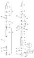
도 2 는 본 발명에 따른 스타일러스 펜의 사시도.
도 3 은 도2에 도시된 스타일러스 펜의 분해 도면.
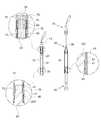
도 4 는 본 발명에 따른 스타일러스 펜의 인입 및 인출 상태의 단면도.
도 5 는 다른 실시례의 척부재가 적용된 스타일러스 펜의 인입 및 인출 상태의 단면도.
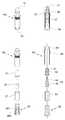
도 6 은 가압부재의 변형예에 대한 도면.1 is a cross-sectional view of the retracted and withdrawn state of the stylus pen according to the prior art.
2 is a perspective view of a stylus pen according to the present invention;
3 is an exploded view of the stylus pen shown in FIG.
4 is a cross-sectional view of the retracted and withdrawn states of the stylus pen according to the present invention.
5 is a cross-sectional view of a retracted and withdrawn state of the stylus pen to which the chuck member of another embodiment is applied.
6 is a view of a modification of the pressing member.
이하 첨부된 도면을 참고하여 본 발명을 상세히 설명하도록 한다.
Hereinafter, the present invention will be described in detail with reference to the accompanying drawings.
본 발명은 다양한 변경을 가할 수 있고 여러 가지 형태를 가질 수 있는 바, 구현예(態樣, aspect)(또는 실시예)들을 본문에 상세하게 설명하고자 한다. 그러나 이는 본 발명을 특정한 개시 형태에 대해 한정하려는 것이 아니며, 본 발명의 사상 및 기술범위에 포함되는 모든 변경, 균등물 내지 대체물을 포함하는 것으로 이해되어야 한다.The present invention may be modified in various ways and may have various forms, and thus embodiments (or embodiments) will be described in detail in the text. However, this is not intended to limit the present invention to the specific form disclosed, it should be understood to include all modifications, equivalents, and substitutes included in the spirit and scope of the present invention.
각 도면에서 동일한 참조부호, 특히 십의 자리 및 일의 자리 수, 또는 십의 자리, 일의 자리 및 알파벳이 동일한 참조부호는 동일 또는 유사한 기능을 갖는 부재를 나타내고, 특별한 언급이 없을 경우 도면의 각 참조부호가 지칭하는 부재는 이러한 기준에 준하는 부재로 파악하면 된다.In each of the drawings, the same reference numerals, in particular, the tens and ones digits, or the same digits, tens, ones, and alphabets refer to members having the same or similar functions, and unless otherwise specified, each member in the figures The member referred to by the reference numeral may be regarded as a member conforming to these criteria.
또 각 도면에서 구성요소들은 이해의 편의 등을 고려하여 크기나 두께를 과장되게 크거나(또는 두껍게) 작게(또는 얇게) 표현하거나, 단순화하여 표현할 수 있으나 이에 의하여 본 발명의 보호범위가 제한적으로 해석되어서는 안 된다.In addition, the components in each of the drawings may be represented by an excessively large (or thick) small (or thin) or simplified by considering the convenience of understanding or the like, thereby limiting the protection scope of the present invention It should not be.
본 명세서에서 사용한 용어는 단지 특정한 구현예(태양, 態樣, aspect)(또는 실시예)를 설명하기 위해 사용된 것으로, 본 발명을 한정하려는 의도가 아니다. 단수의 표현은 문맥상 명백하게 다르게 뜻하지 않는 한, 복수의 표현을 포함한다. 본 출원에서, ~포함하다~ 또는 ~이루어진다~ 등의 용어는 명세서 상에 기재된 특징, 숫자, 단계, 동작, 구성요소, 부분품 또는 이들을 조합한 것이 존재함을 지정하려는 것이지, 하나 또는 그 이상의 다른 특징들이나 숫자, 단계, 동작, 구성요소, 부분품 또는 이들을 조합한 것들의 존재 또는 부가 가능성을 미리 배제하지 않는 것으로 이해되어야 한다.The terminology used herein is for the purpose of describing particular embodiments (suns, aspects, and embodiments) (or embodiments) only and is not intended to be limiting of the invention. Singular expressions include plural expressions unless the context clearly indicates otherwise. In this application, the terms “comprises” or “consists” are intended to indicate that there is a feature, number, step, action, component, part, or combination thereof described on the specification, but one or more other features. It is to be understood that the present invention does not exclude the possibility of the presence or the addition of numbers, steps, operations, components, parts, or combinations thereof.
다르게 정의되지 않는 한, 기술적이거나 과학적인 용어를 포함해서 여기서 사용되는 모든 용어들은 본 발명이 속하는 기술 분야에서 통상의 지식을 가진 자에 의해 일반적으로 이해되는 것과 동일한 의미를 가지고 있다. 일반적으로 사용되는 사전에 정의되어 있는 것과 같은 용어들은 관련 기술의 문맥 상 가지는 의미와 일치하는 의미를 가지는 것으로 해석되어야 하며, 본 출원에서 명백하게 정의하지 않는 한, 이상적이거나 과도하게 형식적인 의미로 해석되지 않는다.
Unless defined otherwise, all terms used herein, including technical or scientific terms, have the same meaning as commonly understood by one of ordinary skill in the art. Terms such as those defined in the commonly used dictionaries should be construed as having meanings consistent with the meanings in the context of the related art and shall not be construed in ideal or excessively formal meanings unless expressly defined in this application. Do not.
본 발명은 도면에서 보는 바와 같이 실린더 바디(10), 피스톤 로드(20), 가압부재(30), 척부재(40), 캡부재(70)를 포함하여 이루어진다. 참고로, 이하에서 본 발명을 설명함에 있어 부가되는 도면부호는 도1의 종래기술에 도시된 도면부호와 무관하다.
The present invention comprises a
상기 실린더 바디(10)는 내측에 전후방을 관통하는 수용부(11)가 형성되어 있고, 상기 수용부(11) 전방 내면에는 바디캡(60)의 외주연이 스크류결합되는 나사산(15)이 형성되어 있고, 후방 내면에는 강제 삽입된 상기 척부재(40)의 고정돌기(41)가 안착되어 걸리는 고정홈(13)이 형성되어 있다.The
상기 바디캡(60)은 스크류결합 외에 접착제로 상기 실린더 바디(10) 내면에 부착되어 결합되거나, 억지끼움방식으로 결합될 수도 있다.
The
상기 피스톤 로드(20)는 상기 실린더 바디(10)의 수용부(11)에 수용되고, 수용부(11)를 따라 전후진하여 수용부(11)에 인입 및 인출된다.The
상기 피스톤 로드(20)는 샤프트(21), 가이드부재(23), 파지부재(25)를 포함하여 이루어진다.The
상기 샤프트(21)는 내측에 전후방을 관통하는 관통홀(22)이 형성되어 있다.The
상기 가이드부재(23) 및 파지부재(25)는 각각 상기 샤프트(21)의 전방과 후방에서 상기 관통홀(22)에 강제 삽입되어 고정 결합된다.
The
그리고 도면에서는 단일 실린더 바디(10)와 단일 피스톤 로드(20)(특히 샤프트(21))를 사용하여 스타일러스 펜이 2단으로 인출되는 것을 도시하고 있는데, 실린더 바디(10) 또는 피스톤 로드(20)를 인입 및 인출이 가능하게 다수 구비하여 다단으로 인출되도록 할 수도 있다.
In addition, the drawing shows that the stylus pen is drawn out in two stages using a
상기 가이드부재(23)는 상기 샤프트(21)의 전방 관통홀(22)에 삽입되어 결합되는 삽입부(233)와, 상기 삽입부(233)에 연결되고 상기 실린더 바디(10)의 수용부(11) 내면에 접촉되어 샤프트(21)의 직선왕복운동(즉, 인입 및 인출 동작)을 가이드하는 접촉부(235)를 포함하여 이루어진다.
The
그리고 상기 접촉부(235)는 왕복운동시 샤프트(21)가 좌우로 움직임 없이 최대한 전후방향으로 직선 운동할 수 있도록 충분한 길이를 가지며, 접촉부(235) 외주연에는 수용부(11) 내면과의 밀착력을 높이도록 얇은 고무패킹(237) 2개가 일정거리 이격되어 결합되어 있다.
In addition, the
또한, 고무패킹(237)에 의해 수용부(11) 내면에 밀착되는 접촉부(235)에는 접촉부(235) 내외부를 공간적으로 연결하여 가이드부재(23)의 왕복운동에 따라 내외부의 공기가 이동(유입 및 유출)되도록 하여 가이드부재(23)의 왕복운동이 원활하게 이루어지도록 하는 슬릿홈(236)이 형성되어 있다.
In addition, the inner and outer air moves in accordance with the reciprocating motion of the
그리고 상기 삽입부와 접촉부(235) 사이의 외주연에는 상기 척부재(40)의 전방걸림홈(43)에 안착되어 걸리는 걸림부(231)가 환형으로 돌출형성되어 있다.
And at the outer periphery between the insertion portion and the
상기 파지부재(25)는 상기 샤프트(21)의 후방 관통홀(22)에 삽입되는 삽입부(253)와, 상기 삽입부(253)와 연결되고 상기 실린더 바디(10) 후방으로 노출되는 파지부(255)를 포함하여 이루어진다.
The gripping
상기 파지부(255)의 외주연에는 사용자가 파지하여 잡아당길때(즉, 피스톤 로드(20)를 인출시킬때) 파지하기 용이하도록 파지홈(256)이 형성되어 있다.
The outer periphery of the
그리고 상기 삽입부(253)와 파지부(255) 사이의 외주연에는 상기 척부재(40)의 후방걸림홈(45)에 안착되어 걸리는 걸림부(251)가 환형으로 돌출형성되어 있다.
And at the outer circumference between the
상기 척부재(40)는 상기 실린더 바디(10)의 수용부(11) 후방에 강제 삽입되어 결합된다.The
척부재(40)의 외주연에는 상기 수용부(11) 내면에 형성되어 있는 고정홈(13)에 안착되어 고정결합되는 고정돌기(41)가 환형으로 형성되어 있고,The outer periphery of the
내면 전방에는 인출된 상기 피스톤 로드(20)의 가이드부재(23)에 형성되어 있는 걸림부(231)가 안착되어 걸리는 전방걸림홈(43)가 형성되어 있고, 내면 후방에는 인입된 피스톤 로드(20)의 파지부재(25)에 형성되어 있는 걸림부(251)가 안착되어 걸리는 후방걸림홈(45)가 형성되어 있다.In front of the inner surface is formed a
그리고 상기 전방걸림홈(43)의 전방과 후방걸림홈(45)의 후방은 경사져 있어, 전후진 하는 걸림부(231,253)가 쉽게 타고 넘어갈 수 있도록 한다.
And the front of the
그리고 상기 척부재(40)가 삽입된 실린더 바디(10)의 후방 수용부(11)에는 바디링(50)이 삽입 결합되어 척부재(40)가 수용부(11)에서 분리이탈되는 것을 방지한다.
The
도5에는 피스톤로드(20)의 비의도적 인입과 인출을 방지하는 다른 실시례의 척부재(40a, 40b)가 도시되어 있다.FIG. 5 shows
도5에 도시된 척부재는 실린더 바디(10)의 하부에 결합되어 피스톤 로드(20)의 비의도적 인입을 방지하는 제1척(40a)과 실린더 바다의 상부에 결합되어 피스톤 로드의 비의도적 인출을 방지하는 제2척(40a)으로 구성된다.The chuck member shown in FIG. 5 is coupled to the lower portion of the
상기 제1척(40a)의 외주연에는 실린더 바디의 고정홈(10)에 안착되어 걸리는 고정돌기(41a)가 형성되어 있고, 내면에는 상기 가이드부재(23)의 걸림부(231)가 안착되어 걸리는 걸림홈(43a)이 형성되어 있다.The outer periphery of the first chuck (40a) is formed with a fixing projection (41a) to be seated in the fixing
상기 제2척(40b)의 외주연 상부에는 상기 실린더 바디의 상부 내면에 형성되어 있는 단턱에 걸리는 걸림단턱(41b)이 형성되어 있고, 내면에는 상기 가이드부재의 상부 외주연에 형성되어 있는 또 다른 걸림부(232)가 안착되어 걸리는 걸림홈(42b)가 형성되어 있다.On the outer circumferential upper portion of the
상기 바디캡(60)은 상기 실린더 바디(10)의 전방 수용부(11)에 스크류 결합된다.The
상기 바디캡(60)의 후방 외주연에는 상기 수용부(11) 내면에 형성된 나사산(15)에 스크류결합되도록 대응나사산(65)이 형성되어 있고, 전방 외주연에는 상기 캡부재(70)의 바디척(73)에 형성되어 있는 요철(74)이 안착되어 걸리는 요홈(64)이 형성되어 있다.
A
상기 가압부재(30)는 상기 실린더 바디(10)의 전단 또는 피스톤 로드(20)의 전단에 결합되고, 터치 스크린 표면을 가압하여 정보를 입력하게 된다. 다시 말해, 도면과 같이 피스톤 로드(20)가 실린더 바디의 후방으로 인출되는 타입의 스타일러스 펜에서는 가압부재(30)가 실린더 바디(10) 전단에 결합되고, 피스톤 로드(20)가 전방으로 인출되는 타입에서는 피스톤 로드(20) 전단에 결합된다.
The pressing
상기 가압부재(30)는 러버팁(31)과 결합핀(33)을 포함하여 이루어진다.The pressing
상기 러버팁(31)은 탄성을 갖는 고무재질로 이루어져 스크린 표면에 접촉 가압시 스크린 표면에 무리를 주지 아니하고, 도전성의 성질이 있어 스크린 표면에 터치 시에 스크린 접촉부(235)위의 정전용량을 변화시킨다.
The
상기 결합핀(33)은 상기 바디캡(60)에 삽입 결합되는 결합부(35)와, 상기 결합부(35)에 연결되고 상기 바디캡(60) 외부로 노출되며 상기 러버팁(31)의 수용홈(32)에 삽입 수용되는 핀부(34)로 구성된다.
The
그리고 상기 핀부(34)와 상기 러버팁(31)의 내면 사이에는 유격 공간(36)이 있다. 그리하여 가압부재(30)가 스크린을 터치하는 때에 러버팁(31)이 스크린에 접촉 후에 유격 공간(36)만큼 후진하여 순간적으로 스크린에 가해지는 힘을 분산시켜 완충시키고, 또한 후진한 만큼 러버팁(31)과 스크린의 접촉면적이 늘어나게 된다.
In addition, there is a
그리고 상기 가압부재(30)는 러버팁(31)과 결합핀(33) 이외에 도6에 도시된 것과 같이 고정부재(38)와 연결부재(37)를 더 포함할 수 있다.
In addition to the
스타일러스 펜에서는 가압부재(30)에 가장 많은 하중이 반복적, 지속적으로 가해진다. 그래서 장기간 사용하게 되면 반복적으로 가해지는 하중에 의해 가압부재(30)가 뒤로 밀려 바디캡(60)에서 분리이탈될 소지가 있고, 이를 방지하기 위한 것이 상기 고정부재(38)와 연결부재(37)이다.
In the stylus pen, the most load is repeatedly and continuously applied to the pressing
상기 연결부재(37)의 전방에는 상기 결합핀(33)이 삽입결합되고, 후방에는 상기 고정부재(38)가 삽입결합된다.
The
상기 고정부재(38)는 상기 바디캡(60)의 후방에서 전방으로 삽입되어 결합된다.The fixing
그리고 바디캡(60) 내면과 접촉되는 고정부재(38)의 외주연에는 전방으로 전진은 허용하면서 후방으로 후진은 허용하지 아니하도록 테이퍼진 테이퍼돌기(381)가 다수 형성되어 있다.
In addition, a plurality of tapered
또한, 상기 테이퍼돌기(381)에는 표면을 절삭한 절삭홈(383) 곳곳에 형성되어, 하나의 테이퍼돌기(381)를 낚시바늘의 미늘과 같은 다수의 단위테이퍼돌기로 분리시켜 고정부재(38)가 바디캡(60)에서 보다 강력히 분리이탈되지 않도록 하였다.
In addition, the tapered
상기 캡부재(70)는 상기 실린더 바디(10)의 전방에 탈착 가능하게 결합되고, 뚜껑(71)과, 바디척(73)과, 캡링(75)을 포함하여 이루어진다.The
상기 뚜껑(71)에는 휴대폰이나 열쇠고리 등에 걸을 수 있도록 고리줄이 구비된다.The
상기 바디척(73)은 상기 뚜껑(71) 내면에 삽입결합되고, 내면에는 상기 바디캡(60)의 요홈(64)에 안착되어 결합되어 탈착이 되도록 하는 요철(74)이 형성되어 있다.The
상기 캡링(75)은 상기 바디척(73)이 삽입결합된 상기 뚜껑(71) 내면에 삽입 결합되어 바디척(73)의 분리이탈을 방지한다.
The
이상에서 본 발명을 설명함에 있어 첨부된 도면을 참조하여 특정 형상과 구조를 갖는 스타일러스 펜에 대해 설명하였으나 본 발명은 당업자에 의하여 다양한 변형 및 변경이 가능하고, 이러한 변형 및 변경은 본 발명의 보호범위에 속하는 것으로 해석되어야 한다.
In the above description of the present invention, a stylus pen having a specific shape and structure has been described with reference to the accompanying drawings, but the present invention can be variously modified and changed by those skilled in the art, and such modifications and changes are the scope of protection of the present invention. Should be interpreted as belonging to.
10 : 실린더 바디 11 : 수용부
13 : 고정홈 15 : 나사산
20 : 피스톤 로드 21 : 샤프트
23 : 가이드부재 25 : 파지부재
30 : 가압부재 31 : 러버팁
33 : 결합핀 36 : 유격 공간
37 : 연결부재 38 : 고정부재
40 : 척부재 41 : 고정돌기
43 : 전방걸림홈 45 : 후방걸림홈
50 : 바디링 60 : 바디캡
70 : 캡부재 71 : 뚜껑
73 : 바디척 75 : 캡링10: cylinder body 11: receiving portion
13: fixing groove 15: thread
20: piston rod 21: shaft
23: guide member 25: gripping member
30: pressure member 31: rubber tip
33: coupling pin 36: play space
37
40: chuck member 41: fixed protrusion
43: front locking groove 45: rear locking groove
50: body ring 60: body cap
70
73: body chuck 75: capping
Claims (4)
Translated fromKorean상기 실린더 바디에 수용되어 인입 및 인출되는 피스톤 로드;
상기 실린더 바디의 전단 또는 상기 피스톤 로드의 전단에 결합되어 있는 정보입력 터치용 가압부재;
상기 실린더 바디 내면에 삽입 결합되고, 상기 피스톤 로드가 비의도적으로 인출 및 인입되는 것을 방지하는 척부재;
상기 실린더 바디의 전방 내면에 결합되어 고정되고, 상기 가압부재가 삽입 결합되어 고정되는 바디캡;를 포함하여 이루어지되,
상기 가압부재는
도전성을 갖는 러버팁과,
상기 러버팁에 삽입결합되는 결합핀과,
전방에 상기 결합핀이 삽입결합되는 연결부재와,
상기 연결부재의 후방에 삽입결합되고, 상기 바디캡의 후방에서 전방으로 삽입되어 결합되며, 상기 바디캡 내면과 접촉되는 외주연에는 테이퍼진 테이퍼돌기가 다수 형성되어 있고, 상기 테이퍼돌기에는 표면을 절삭한 절삭홈이 곳곳에 형성되어 있는 고정부재를 포함하여 이루어져,
상기 결합핀의 단부와 상기 러버팁의 내면 사이에는 유격이 있어, 상기 러버팁의 터치 스크린 표면을 가압하는 경우에 러버팁의 접촉면적이 증가되고,
상기 테이퍼돌기는 전방으로 전진은 허용하면서 후방으로 후진은 허용하지 아니하도록 하는 것을 특징으로 하는 스타일러스 펜.Cylinder body;
A piston rod accommodated in the cylinder body and drawn in and drawn out;
An information input touch pressing member coupled to the front end of the cylinder body or the front end of the piston rod;
A chuck member inserted into the inner surface of the cylinder body and preventing the piston rod from being unintentionally drawn out and drawn out;
Is coupled to the front inner surface of the cylinder body is fixed, the body member is inserted and coupled to the pressing member fixed;
The pressing member is
Rubber tip having electroconductivity,
A coupling pin inserted and coupled to the rubber tip,
A connection member to which the coupling pin is inserted and coupled to the front;
Inserted and coupled to the rear of the connecting member, and inserted and coupled to the front from the rear of the body cap, a plurality of tapered tapered protrusions are formed on the outer periphery contacting the inner surface of the body cap, the tapered protrusion to cut the surface One cutting groove includes a fixed member formed in various places,
There is a play between the end of the coupling pin and the inner surface of the rubber tip, the contact area of the rubber tip is increased when pressing the surface of the rubber tip,
The tapered protrusion is stylus pen, characterized in that to allow forward movement forward but not backward.
상기 피스톤 로드의 상부와 하부에 각각 걸림부가 구비되어 있고,
상기 척부재는 상기 피스톤 로드가 상기 실린더 바디에 인입 및 인출된 상태에서 상부 또는 하부의 상기 걸림부가 걸림결합되어 피스톤 로드가 비의도적으로 인출 및 인입되는 것을 방지하는 것을 특징으로 하는 스타일러스 펜.The method of claim 1,
Engaging portions are provided on the upper and lower portions of the piston rod,
The chuck member is a stylus pen, characterized in that the engaging portion of the upper or lower engaging portion in the state that the piston rod is drawn in and drawn out of the cylinder body to prevent the piston rod is unintentionally drawn out and drawn out.
상기 피스톤 로드는
상기 실린더 바디의 수용부에 삽입 수용되는 샤프트와,
상기 샤프트 전단에 결합되고, 상기 수용부 내면에 접촉되어 상기 샤프트의 직선 왕복운동을 가이드하는 가이드부재와,
상기 샤프트 후단에 결합되고, 후단이 상기 실린더 바디 후방에 노출되어 사용자가 파지하는 파지부재를 포함하여 이루어지되,
상기 가이드부재 및 파지부재의 외주연에는 각각 상기 척부재에 걸림결합되는 걸림부가 돌출형성되어 있는 것을 특징으로 하는 스타일러스 펜.The method of claim 1,
The piston rod is
A shaft inserted into and received in the accommodation portion of the cylinder body;
A guide member coupled to the front end of the shaft and in contact with an inner surface of the receiving part to guide linear reciprocation of the shaft;
It is coupled to the rear end of the shaft, the rear end is made to include a holding member exposed to the rear of the cylinder body, the user grips,
Stylus pens, characterized in that the engaging portion engaging with the chuck member is formed on the outer periphery of the guide member and the gripping member.
상기 실린더 바디의 전방 내면에 결합되어 고정되고, 상기 가압부재가 삽입 결합되어 고정되는 바디캡을 더 포함하고,
상기 척부재의 외주연에는 상기 실린더 바디 내면에 형성되어 있는 고정홈에 안착되어 고정결합되는 고정돌기가 돌출형성되어 있고, 내면 전방에는 상기 가이드부재의 걸림부가 걸리는 전방걸림홈이 형성되어 있고, 내면 후방에는 상기 파지부재의 걸림부가 걸리는 후방걸림홈이 형성되어 있는 것을 특징으로 하는 스타일러스 펜.The method of claim 3, wherein
And a body cap fixedly coupled to the front inner surface of the cylinder body and inserted into and fixed to the pressing member.
The outer periphery of the chuck member is formed with a projection is fixed to the fixed groove formed on the inner surface of the cylinder body fixedly coupled to the projection, the front surface of the inner surface is formed with a front locking groove that the engaging portion of the guide member is caught, Stylus pen, characterized in that the rear engaging groove is formed on the rear of the holding portion of the holding member.
Applications Claiming Priority (2)
| Application Number | Priority Date | Filing Date | Title |
|---|---|---|---|
| KR20100041210 | 2010-05-03 | ||
| KR1020100041210 | 2010-05-03 |
Publications (1)
| Publication Number | Publication Date |
|---|---|
| KR100994814B1true KR100994814B1 (en) | 2010-11-17 |
Family
ID=43409804
Family Applications (3)
| Application Number | Title | Priority Date | Filing Date |
|---|---|---|---|
| KR1020100042366AActiveKR100994814B1 (en) | 2010-05-03 | 2010-05-06 | Stylus pen |
| KR1020100075451AActiveKR101003070B1 (en) | 2010-05-03 | 2010-08-05 | Stylus pen |
| KR1020100115337AActiveKR101027441B1 (en) | 2010-05-03 | 2010-11-19 | Stylus pen |
Family Applications After (2)
| Application Number | Title | Priority Date | Filing Date |
|---|---|---|---|
| KR1020100075451AActiveKR101003070B1 (en) | 2010-05-03 | 2010-08-05 | Stylus pen |
| KR1020100115337AActiveKR101027441B1 (en) | 2010-05-03 | 2010-11-19 | Stylus pen |
Country Status (1)
| Country | Link |
|---|---|
| KR (3) | KR100994814B1 (en) |
Cited By (4)
| Publication number | Priority date | Publication date | Assignee | Title |
|---|---|---|---|---|
| KR101071935B1 (en) | 2011-05-18 | 2011-10-12 | 김용태 | Touch pen |
| KR101182902B1 (en) | 2011-04-19 | 2012-09-13 | 가부시키가이샤 와코무 | Cordless type position pointer |
| KR101200971B1 (en) | 2010-10-13 | 2012-11-13 | 주식회사 지엠텍 | touch apparatus for touch screen |
| KR200464737Y1 (en) | 2012-07-05 | 2013-01-15 | 제 혁 이 | Elongated stylus pen with idle prevention function |
Families Citing this family (8)
| Publication number | Priority date | Publication date | Assignee | Title |
|---|---|---|---|---|
| WO2012087026A2 (en)* | 2010-12-23 | 2012-06-28 | Son Jong-Wook | Functional accessory for gloves |
| KR101064314B1 (en)* | 2010-12-30 | 2011-09-14 | 김동국 | Stylus pen |
| KR101071927B1 (en)* | 2010-12-31 | 2011-10-12 | 문인식 | Stylus pen |
| KR200465913Y1 (en)* | 2011-01-12 | 2013-03-19 | (주)삼원에스티 | Touch pen for touch sceen panel |
| KR101218762B1 (en) | 2011-04-20 | 2013-01-09 | 정광수 | a touch pen |
| KR101218760B1 (en) | 2011-04-20 | 2013-01-09 | 정광수 | Capacitive touch pen using pencil lead |
| KR101078392B1 (en) | 2011-07-08 | 2011-10-31 | 주식회사 제이아이테크 | Stylus pen with air leak-proof touch member |
| CN106325554B (en)* | 2016-08-18 | 2023-04-07 | 汉王科技股份有限公司 | Capacitive pen, manufacturing method thereof, pen point assembly and touch device |
Citations (1)
| Publication number | Priority date | Publication date | Assignee | Title |
|---|---|---|---|---|
| KR100930816B1 (en) | 2008-07-10 | 2009-12-09 | 배종현 | External slim stylus pen for mobile devices |
Family Cites Families (7)
| Publication number | Priority date | Publication date | Assignee | Title |
|---|---|---|---|---|
| JPH10161795A (en)* | 1996-12-03 | 1998-06-19 | Mitsubishi Pencil Co Ltd | Input pen for electrostatic capacity-type coordinate input pad |
| JP4142776B2 (en)* | 1998-10-15 | 2008-09-03 | パイロットプレシジョン株式会社 | Input pen |
| JP2000172425A (en) | 1998-12-09 | 2000-06-23 | Japan Aviation Electronics Industry Ltd | Capacitive tablet input pen |
| KR100776369B1 (en) | 2007-01-26 | 2007-11-15 | 나현주 | Multistage stylus pen |
| US8125469B2 (en) | 2008-04-18 | 2012-02-28 | Synaptics, Inc. | Passive stylus for capacitive sensors |
| KR20100104138A (en)* | 2009-03-16 | 2010-09-29 | (주)동현테크노 | Styluspen |
| KR20100007569U (en)* | 2010-07-01 | 2010-07-26 | 이호선 | Inductive Stylus Touch Pen |
- 2010
- 2010-05-06KRKR1020100042366Apatent/KR100994814B1/enactiveActive
- 2010-08-05KRKR1020100075451Apatent/KR101003070B1/enactiveActive
- 2010-11-19KRKR1020100115337Apatent/KR101027441B1/enactiveActive
Patent Citations (1)
| Publication number | Priority date | Publication date | Assignee | Title |
|---|---|---|---|---|
| KR100930816B1 (en) | 2008-07-10 | 2009-12-09 | 배종현 | External slim stylus pen for mobile devices |
Cited By (6)
| Publication number | Priority date | Publication date | Assignee | Title |
|---|---|---|---|---|
| KR101200971B1 (en) | 2010-10-13 | 2012-11-13 | 주식회사 지엠텍 | touch apparatus for touch screen |
| KR101182902B1 (en) | 2011-04-19 | 2012-09-13 | 가부시키가이샤 와코무 | Cordless type position pointer |
| EP2515207A1 (en)* | 2011-04-19 | 2012-10-24 | Wacom Co., Ltd. | Cordless type position pointer |
| US8576203B2 (en) | 2011-04-19 | 2013-11-05 | Wacom Co., Ltd. | Cordless type position pointer |
| KR101071935B1 (en) | 2011-05-18 | 2011-10-12 | 김용태 | Touch pen |
| KR200464737Y1 (en) | 2012-07-05 | 2013-01-15 | 제 혁 이 | Elongated stylus pen with idle prevention function |
Also Published As
| Publication number | Publication date |
|---|---|
| KR101027441B1 (en) | 2011-04-06 |
| KR101003070B1 (en) | 2010-12-21 |
Similar Documents
| Publication | Publication Date | Title |
|---|---|---|
| KR100994814B1 (en) | Stylus pen | |
| KR101940565B1 (en) | Stylus pen and electronic device having the same | |
| CN201078770Y (en) | Telescopic touch control pen of electric device | |
| US8217919B2 (en) | Stylus retaining and releasing mechanism | |
| US8194055B2 (en) | Stylus retaining mechanism for portable electronic device | |
| US20090050378A1 (en) | Stylus and portable electronic device using the same | |
| US20110193827A1 (en) | Stylus | |
| CN110341349B (en) | Self-locking lifting pen | |
| US8436838B2 (en) | Touch pen | |
| US8373681B2 (en) | Stylus having a retracted and extended position | |
| KR100985061B1 (en) | Conductive type touch pen | |
| JP7096412B2 (en) | Stationery with stylus | |
| US20110227880A1 (en) | Telescoping stylus for portable electronic device | |
| US20110234546A1 (en) | Stylus | |
| CN112835460A (en) | Writing pen | |
| KR100557123B1 (en) | Stylus pen | |
| JP6061733B2 (en) | Capacitive touch pen | |
| KR20110113801A (en) | Electrostatic decompression touch pen | |
| CN102103420B (en) | Touch pen | |
| US20130322952A1 (en) | Multi-functional stylus | |
| KR102135322B1 (en) | Improved touch pen for use of touch screen | |
| US20110169784A1 (en) | Stylus retaining mechanism for portable electronic device | |
| KR200457156Y1 (en) | Capacitive Type Stylus Pen | |
| CN112823329A (en) | Touch control pen | |
| CN219800121U (en) | Touch control pen |
Legal Events
| Date | Code | Title | Description |
|---|---|---|---|
| PA0109 | Patent application | Patent event code:PA01091R01D Comment text:Patent Application Patent event date:20100506 | |
| A201 | Request for examination | ||
| A302 | Request for accelerated examination | ||
| PA0201 | Request for examination | Patent event code:PA02012R01D Patent event date:20100511 Comment text:Request for Examination of Application Patent event code:PA02011R01I Patent event date:20100506 Comment text:Patent Application | |
| PA0302 | Request for accelerated examination | Patent event date:20100511 Patent event code:PA03022R01D Comment text:Request for Accelerated Examination Patent event date:20100506 Patent event code:PA03021R01I Comment text:Patent Application | |
| E902 | Notification of reason for refusal | ||
| PE0902 | Notice of grounds for rejection | Comment text:Notification of reason for refusal Patent event date:20100715 Patent event code:PE09021S01D | |
| E90F | Notification of reason for final refusal | ||
| PE0902 | Notice of grounds for rejection | Comment text:Final Notice of Reason for Refusal Patent event date:20101019 Patent event code:PE09021S02D | |
| E701 | Decision to grant or registration of patent right | ||
| PE0701 | Decision of registration | Patent event code:PE07011S01D Comment text:Decision to Grant Registration Patent event date:20101104 | |
| GRNT | Written decision to grant | ||
| PR0701 | Registration of establishment | Comment text:Registration of Establishment Patent event date:20101110 Patent event code:PR07011E01D | |
| PR1002 | Payment of registration fee | Payment date:20101111 End annual number:3 Start annual number:1 | |
| PG1601 | Publication of registration | ||
| FPAY | Annual fee payment | Payment date:20131025 Year of fee payment:4 | |
| PR1001 | Payment of annual fee | Payment date:20131025 Start annual number:4 End annual number:4 | |
| FPAY | Annual fee payment | Payment date:20141031 Year of fee payment:5 | |
| PR1001 | Payment of annual fee | Payment date:20141031 Start annual number:5 End annual number:5 | |
| FPAY | Annual fee payment | Payment date:20151111 Year of fee payment:6 | |
| PR1001 | Payment of annual fee | Payment date:20151111 Start annual number:6 End annual number:6 | |
| FPAY | Annual fee payment | Payment date:20161110 Year of fee payment:7 | |
| PR1001 | Payment of annual fee | Payment date:20161110 Start annual number:7 End annual number:7 | |
| FPAY | Annual fee payment | Payment date:20171109 Year of fee payment:8 | |
| PR1001 | Payment of annual fee | Payment date:20171109 Start annual number:8 End annual number:8 | |
| FPAY | Annual fee payment | Payment date:20181108 Year of fee payment:9 | |
| PR1001 | Payment of annual fee | Payment date:20181108 Start annual number:9 End annual number:9 | |
| PR1001 | Payment of annual fee | Payment date:20201103 Start annual number:11 End annual number:11 | |
| PR1001 | Payment of annual fee | Payment date:20211109 Start annual number:12 End annual number:12 | |
| PR1001 | Payment of annual fee | Payment date:20221110 Start annual number:13 End annual number:13 | |
| PR1001 | Payment of annual fee | Payment date:20231108 Start annual number:14 End annual number:14 |