KR100993108B1 - Grid-connected photovoltaic power generation system with improved power quality and power saving - Google Patents
Grid-connected photovoltaic power generation system with improved power quality and power savingDownload PDFInfo
- Publication number
- KR100993108B1 KR100993108B1KR1020080050783AKR20080050783AKR100993108B1KR 100993108 B1KR100993108 B1KR 100993108B1KR 1020080050783 AKR1020080050783 AKR 1020080050783AKR 20080050783 AKR20080050783 AKR 20080050783AKR 100993108 B1KR100993108 B1KR 100993108B1
- Authority
- KR
- South Korea
- Prior art keywords
- power
- inverter
- voltage
- grid
- load
- Prior art date
- Legal status (The legal status is an assumption and is not a legal conclusion. Google has not performed a legal analysis and makes no representation as to the accuracy of the status listed.)
- Expired - Fee Related
Links
Images


Classifications
- H—ELECTRICITY
- H02—GENERATION; CONVERSION OR DISTRIBUTION OF ELECTRIC POWER
- H02J—CIRCUIT ARRANGEMENTS OR SYSTEMS FOR SUPPLYING OR DISTRIBUTING ELECTRIC POWER; SYSTEMS FOR STORING ELECTRIC ENERGY
- H02J3/00—Circuit arrangements for AC mains or AC distribution networks
- H02J3/18—Arrangements for adjusting, eliminating or compensating reactive power in networks
- H02J3/1807—Arrangements for adjusting, eliminating or compensating reactive power in networks using series compensators
- H02J3/1814—Arrangements for adjusting, eliminating or compensating reactive power in networks using series compensators wherein al least one reactive element is actively controlled by a bridge converter, e.g. unified power flow controllers [UPFC]
- H—ELECTRICITY
- H02—GENERATION; CONVERSION OR DISTRIBUTION OF ELECTRIC POWER
- H02J—CIRCUIT ARRANGEMENTS OR SYSTEMS FOR SUPPLYING OR DISTRIBUTING ELECTRIC POWER; SYSTEMS FOR STORING ELECTRIC ENERGY
- H02J3/00—Circuit arrangements for AC mains or AC distribution networks
- H02J3/38—Arrangements for parallely feeding a single network by two or more generators, converters or transformers
- H—ELECTRICITY
- H02—GENERATION; CONVERSION OR DISTRIBUTION OF ELECTRIC POWER
- H02J—CIRCUIT ARRANGEMENTS OR SYSTEMS FOR SUPPLYING OR DISTRIBUTING ELECTRIC POWER; SYSTEMS FOR STORING ELECTRIC ENERGY
- H02J3/00—Circuit arrangements for AC mains or AC distribution networks
- H02J3/18—Arrangements for adjusting, eliminating or compensating reactive power in networks
- H02J3/1821—Arrangements for adjusting, eliminating or compensating reactive power in networks using shunt compensators
- H02J3/1835—Arrangements for adjusting, eliminating or compensating reactive power in networks using shunt compensators with stepless control
- H02J3/1842—Arrangements for adjusting, eliminating or compensating reactive power in networks using shunt compensators with stepless control wherein at least one reactive element is actively controlled by a bridge converter, e.g. active filters
- H—ELECTRICITY
- H02—GENERATION; CONVERSION OR DISTRIBUTION OF ELECTRIC POWER
- H02J—CIRCUIT ARRANGEMENTS OR SYSTEMS FOR SUPPLYING OR DISTRIBUTING ELECTRIC POWER; SYSTEMS FOR STORING ELECTRIC ENERGY
- H02J3/00—Circuit arrangements for AC mains or AC distribution networks
- H02J3/38—Arrangements for parallely feeding a single network by two or more generators, converters or transformers
- H02J3/381—Dispersed generators
- H—ELECTRICITY
- H02—GENERATION; CONVERSION OR DISTRIBUTION OF ELECTRIC POWER
- H02J—CIRCUIT ARRANGEMENTS OR SYSTEMS FOR SUPPLYING OR DISTRIBUTING ELECTRIC POWER; SYSTEMS FOR STORING ELECTRIC ENERGY
- H02J3/00—Circuit arrangements for AC mains or AC distribution networks
- H02J3/38—Arrangements for parallely feeding a single network by two or more generators, converters or transformers
- H02J3/46—Controlling of the sharing of output between the generators, converters, or transformers
- H—ELECTRICITY
- H02—GENERATION; CONVERSION OR DISTRIBUTION OF ELECTRIC POWER
- H02J—CIRCUIT ARRANGEMENTS OR SYSTEMS FOR SUPPLYING OR DISTRIBUTING ELECTRIC POWER; SYSTEMS FOR STORING ELECTRIC ENERGY
- H02J7/00—Circuit arrangements for charging or depolarising batteries or for supplying loads from batteries
- H02J7/34—Parallel operation in networks using both storage and other DC sources, e.g. providing buffering
- H02J7/35—Parallel operation in networks using both storage and other DC sources, e.g. providing buffering with light sensitive cells
- H—ELECTRICITY
- H02—GENERATION; CONVERSION OR DISTRIBUTION OF ELECTRIC POWER
- H02M—APPARATUS FOR CONVERSION BETWEEN AC AND AC, BETWEEN AC AND DC, OR BETWEEN DC AND DC, AND FOR USE WITH MAINS OR SIMILAR POWER SUPPLY SYSTEMS; CONVERSION OF DC OR AC INPUT POWER INTO SURGE OUTPUT POWER; CONTROL OR REGULATION THEREOF
- H02M5/00—Conversion of AC power input into AC power output, e.g. for change of voltage, for change of frequency, for change of number of phases
- H02M5/02—Conversion of AC power input into AC power output, e.g. for change of voltage, for change of frequency, for change of number of phases without intermediate conversion into DC
- H02M5/04—Conversion of AC power input into AC power output, e.g. for change of voltage, for change of frequency, for change of number of phases without intermediate conversion into DC by static converters
- H02M5/22—Conversion of AC power input into AC power output, e.g. for change of voltage, for change of frequency, for change of number of phases without intermediate conversion into DC by static converters using discharge tubes with control electrode or semiconductor devices with control electrode
- H02M5/275—Conversion of AC power input into AC power output, e.g. for change of voltage, for change of frequency, for change of number of phases without intermediate conversion into DC by static converters using discharge tubes with control electrode or semiconductor devices with control electrode using devices of a triode or transistor type requiring continuous application of a control signal
- H02M5/293—Conversion of AC power input into AC power output, e.g. for change of voltage, for change of frequency, for change of number of phases without intermediate conversion into DC by static converters using discharge tubes with control electrode or semiconductor devices with control electrode using devices of a triode or transistor type requiring continuous application of a control signal using semiconductor devices only
- H—ELECTRICITY
- H02—GENERATION; CONVERSION OR DISTRIBUTION OF ELECTRIC POWER
- H02J—CIRCUIT ARRANGEMENTS OR SYSTEMS FOR SUPPLYING OR DISTRIBUTING ELECTRIC POWER; SYSTEMS FOR STORING ELECTRIC ENERGY
- H02J2300/00—Systems for supplying or distributing electric power characterised by decentralized, dispersed, or local generation
- H02J2300/20—The dispersed energy generation being of renewable origin
- H02J2300/22—The renewable source being solar energy
- H02J2300/24—The renewable source being solar energy of photovoltaic origin
- H—ELECTRICITY
- H02—GENERATION; CONVERSION OR DISTRIBUTION OF ELECTRIC POWER
- H02M—APPARATUS FOR CONVERSION BETWEEN AC AND AC, BETWEEN AC AND DC, OR BETWEEN DC AND DC, AND FOR USE WITH MAINS OR SIMILAR POWER SUPPLY SYSTEMS; CONVERSION OF DC OR AC INPUT POWER INTO SURGE OUTPUT POWER; CONTROL OR REGULATION THEREOF
- H02M1/00—Details of apparatus for conversion
- H02M1/0083—Converters characterised by their input or output configuration
- H02M1/0093—Converters characterised by their input or output configuration wherein the output is created by adding a regulated voltage to or subtracting it from an unregulated input
- Y—GENERAL TAGGING OF NEW TECHNOLOGICAL DEVELOPMENTS; GENERAL TAGGING OF CROSS-SECTIONAL TECHNOLOGIES SPANNING OVER SEVERAL SECTIONS OF THE IPC; TECHNICAL SUBJECTS COVERED BY FORMER USPC CROSS-REFERENCE ART COLLECTIONS [XRACs] AND DIGESTS
- Y02—TECHNOLOGIES OR APPLICATIONS FOR MITIGATION OR ADAPTATION AGAINST CLIMATE CHANGE
- Y02E—REDUCTION OF GREENHOUSE GAS [GHG] EMISSIONS, RELATED TO ENERGY GENERATION, TRANSMISSION OR DISTRIBUTION
- Y02E10/00—Energy generation through renewable energy sources
- Y02E10/50—Photovoltaic [PV] energy
- Y02E10/56—Power conversion systems, e.g. maximum power point trackers
- Y—GENERAL TAGGING OF NEW TECHNOLOGICAL DEVELOPMENTS; GENERAL TAGGING OF CROSS-SECTIONAL TECHNOLOGIES SPANNING OVER SEVERAL SECTIONS OF THE IPC; TECHNICAL SUBJECTS COVERED BY FORMER USPC CROSS-REFERENCE ART COLLECTIONS [XRACs] AND DIGESTS
- Y02—TECHNOLOGIES OR APPLICATIONS FOR MITIGATION OR ADAPTATION AGAINST CLIMATE CHANGE
- Y02E—REDUCTION OF GREENHOUSE GAS [GHG] EMISSIONS, RELATED TO ENERGY GENERATION, TRANSMISSION OR DISTRIBUTION
- Y02E40/00—Technologies for an efficient electrical power generation, transmission or distribution
- Y02E40/10—Flexible AC transmission systems [FACTS]
- Y—GENERAL TAGGING OF NEW TECHNOLOGICAL DEVELOPMENTS; GENERAL TAGGING OF CROSS-SECTIONAL TECHNOLOGIES SPANNING OVER SEVERAL SECTIONS OF THE IPC; TECHNICAL SUBJECTS COVERED BY FORMER USPC CROSS-REFERENCE ART COLLECTIONS [XRACs] AND DIGESTS
- Y02—TECHNOLOGIES OR APPLICATIONS FOR MITIGATION OR ADAPTATION AGAINST CLIMATE CHANGE
- Y02E—REDUCTION OF GREENHOUSE GAS [GHG] EMISSIONS, RELATED TO ENERGY GENERATION, TRANSMISSION OR DISTRIBUTION
- Y02E40/00—Technologies for an efficient electrical power generation, transmission or distribution
- Y02E40/20—Active power filtering [APF]
- Y—GENERAL TAGGING OF NEW TECHNOLOGICAL DEVELOPMENTS; GENERAL TAGGING OF CROSS-SECTIONAL TECHNOLOGIES SPANNING OVER SEVERAL SECTIONS OF THE IPC; TECHNICAL SUBJECTS COVERED BY FORMER USPC CROSS-REFERENCE ART COLLECTIONS [XRACs] AND DIGESTS
- Y10—TECHNICAL SUBJECTS COVERED BY FORMER USPC
- Y10S—TECHNICAL SUBJECTS COVERED BY FORMER USPC CROSS-REFERENCE ART COLLECTIONS [XRACs] AND DIGESTS
- Y10S323/00—Electricity: power supply or regulation systems
- Y10S323/906—Solar cell systems
Landscapes
- Engineering & Computer Science (AREA)
- Power Engineering (AREA)
- Control Of Electrical Variables (AREA)
- Inverter Devices (AREA)
Abstract
Translated fromKoreanDescription
Translated fromKorean본 발명은 계통연계형 태양광 발전시스템에 관한 것으로, 특히 태양전지로부터 MPPT에 의하여 최대전력을 생산하고, 전원 계통의 역률을 개선하며, 고조파를 저감할 뿐만 아니라 나아가 조명 부하에서 소비되는 전력을 저감할 수 있는 고품질·다기능 계통연계형 태양광 발전시스템에 관한 것이다.The present invention relates to a grid-connected photovoltaic power generation system, and in particular, to produce the maximum power by the MPPT from the solar cell, improve the power factor of the power system, reduce harmonics and further reduce the power consumed in the lighting load The present invention relates to a high-quality, multi-functional grid-connected photovoltaic power generation system that can be done.
최근 국제 유가의 급등 및 지구온난화를 해결하기 위한 온실가스 저감 문제 등으로 화석연료를 대체할 신재생에너지에 관한 연구가 전 세계적으로 주목받고 있다. 특히, 에너지의 97% 이상을 수입에 의존하는 우리나라는 에너지 산업구조를 원천적으로 개선하기 위해 총에너지의 5%를 신재생에너지로 공급한다는 목표를 설정하였으며, 이 중 태양광 발전 시스템인 경우, 태양광 주택 10만호 건설사업, 일반보급사업, 지역보급사업 등 정부 및 지역자치단체 주도하에 급속하게 보급이 확대 되고 있다.Recently, research on renewable energy to replace fossil fuels has been attracting attention all over the world due to soaring international oil prices and GHG reduction to solve global warming. In particular, Korea, which relies on imports for more than 97% of its energy, has set a goal to supply 5% of total energy as renewable energy in order to fundamentally improve the energy industry structure. It is rapidly spreading under the leadership of the government and local governments, including construction projects of 100,000 housing projects, general supply projects, and regional supply projects.
특히, 계통연계형 태양광 발전시스템이 주목을 받고 있는데, 일반적으로 계통연계형 태양광 발전시스템이라 함은 계통전원과 연계된 태양광 발전시스템을 말하는데, 태양광 발전 전력이 부하에서 소비되는 전력에 못 미치는 경우 계통전원으로부터 부족분을 공급받고, 태양광 발전 전력이 부하에서 소비되는 전력을 초과할 경우에는 역으로 그 잉여전력을 계통전원 측으로 공급하여 전체적인 운전 효율을 증가시키는 시스템을 말한다.In particular, grid-connected photovoltaic power generation systems have attracted attention. Generally, grid-connected photovoltaic power generation systems refer to photovoltaic power generation systems linked to grid power sources. If it does not, it receives a shortage from the grid power supply, and if the photovoltaic power exceeds the power consumed by the load, the system supplies the surplus power to the grid power side to increase the overall operating efficiency.
일반적으로 계통 연계형 태양광 발전시스템은 태양전지, MPPT(Maximum Power Point Tracking) 컨버터, 태양전지에서 발전된 전력을 계통에 공급하기 위한 인버터로 구성된다.Generally, grid-connected photovoltaic power generation system is composed of solar cell, maximum power point tracking (MPPT) converter, and inverter to supply power generated from solar cell to grid.
이러한 종래의 계통 연계형 태양광 발전시스템은, 단순히 태양광으로부터 발전된 전력을 컨버터(인버터)의 MPPT 제어에 의하여 계통에 공급하는 방식으로 일사량이 있는 주간에만 이용할 수 있어 높은 설치비에 비하여 이용률이 매우 저조할 뿐만 아니라, 주택 및 오피스 빌딩 등과 같은 비선형 및 역률 부하에 적용 시 태양광 발전에 의한 유효전력 지원으로 계통의 역률을 오히려 악화시키는 문제점이 있었다.The conventional grid-connected photovoltaic power generation system is used only in the daytime with insolation by simply supplying power generated from sunlight to the grid by the MPPT control of the converter (inverter), and thus the utilization rate is very low compared to the high installation cost. In addition, when applied to nonlinear and power factor loads such as homes and office buildings, there was a problem of deteriorating the power factor of the system by supporting active power by solar power.
또한, 종래의 계통 연계형 태양광 발전시스템은 높은 설치비에 비하여 다른 시스템과의 연계 등의 활용도가 낮은 문제점이 있었다.In addition, the conventional grid-tied photovoltaic power generation system has a problem of low utilization, such as linkage with other systems compared to a high installation cost.
따라서, 본 발명의 목적은 상기와 같은 문제점을 해결하기 위한 것으로, 태양광 발전의 최대전력 생산뿐 아니라, 역률 개선, 고조파 저감 등 계통 전력의 품질을 향상시킬 수 있고, 또한 조명 시스템과 연계시켜 조명 부하의 소비전력을 저감시킬 수 있는 계통 연계형 태양광 발전시스템을 제공함에 그 목적이 있다.Accordingly, an object of the present invention is to solve the above problems, and can improve not only the maximum power production of photovoltaic power generation, but also the quality of system power, such as power factor improvement and harmonic reduction, and lighting in conjunction with lighting systems. The purpose is to provide a grid-tied photovoltaic power generation system that can reduce the power consumption of the load.
상기와 같은 목적을 달성하기 위하여, 본 발명에 따른 계통 연계형 태양광 발전시스템은, 태양광을 받아 소정의 전력을 발생시키는 태양전지 어레이와; 상기 태양전지 어레이로부터 발생하는 전력을 계통선에서 요구되는 전력으로 변환하는 제1 인버터와; 상기 제1 인버터와 연결되고, 절전효과를 얻기 위하여 조명부하의 공급전압을 적정전압으로 강압하는 제2 인버터를 포함하여 구성된다.In order to achieve the above object, the grid-tied photovoltaic power generation system according to the present invention, the solar cell array for generating a predetermined power in response to sunlight; A first inverter converting electric power generated from the solar cell array into electric power required by grid lines; And a second inverter connected to the first inverter and configured to step down the supply voltage of the lighting load to a proper voltage in order to obtain a power saving effect.
여기서, 상기 제1 인버터는, 계통 인입 전원에 병렬로 연결되는 전류제어형 전압원 인버터(Current Controlled Voltage Source Inverter, CCVSI)이고, 상기 제2 인버터는, 전원과 부하사이에 직렬로 연결되는 전압제어형 전압원 인버터(Voltage Controlled Voltage Source Inverter, VCVSI)인 것이 바람직하다.Here, the first inverter is a current controlled voltage source inverter (CCVSI) connected in parallel to the grid inlet power supply, the second inverter is a voltage controlled voltage source inverter connected in series between the power supply and the load. (Voltage Controlled Voltage Source Inverter, VCVSI) is preferable.
또한, 본 발명에 따른 계통 연계형 태양광 발전시스템은, 상기 태양전지 어레이로부터 발생되는 전력이 최대이면서, 양질의 전력을 출력하도록 상기 제1 인버터의 동작을 제어하는 MPPT-PQC 통합 제어기와 조명전력절감을 위해 상기 제2 인버 터의 동작을 제어하는 전압제어기를 더 포함하는 것이 바람직하다.In addition, the grid-connected photovoltaic power generation system according to the present invention, the maximum power generated from the solar cell array, the MPPT-PQC integrated controller and lighting power to control the operation of the first inverter to output a high-quality power It is preferable to further include a voltage controller for controlling the operation of the second inverter for saving.
그리고 상기 전압제어기를 태양광 존재 여부에 따라 제어하는 제어기를 더 포함하는 것이 바람직하다.And it is preferable to further include a controller for controlling the voltage controller according to the presence of sunlight.
여기서, 상기 제어기는, 태양광이 존재하지 않는 야간에는, 계통에 양질의 전력을 출력하기 위해 전력 품질 제어(Power Quality Control, PQC)를 수행하는 야간모드와; 태양광이 존재하는 주간에는, 전력 품질 제어(Power Quality Control, PQC)와 최대 전력 추종 제어(Maximum Power Point Tracking, MPPT)를 동시에 수행하는 주간모드로 구분하여 상기 전압제어기를 제어한다.The controller may include a night mode for performing power quality control (PQC) to output high quality power to the system at night when there is no sunlight; During the day in which there is sunlight, the voltage controller is controlled by dividing it into a day mode that simultaneously performs power quality control (PQC) and maximum power point tracking (MPPT).
그리고 본 발명에 따른 계통 연계형 태양광 발전시스템은, 상기 제1 인버터와 상기 제2 인버터 사이에 연결되고, 상기 태양전지 어레이 및 상기 제1 인버터와 상기 제2 인버터 사이의 직류 측에 전압 안정을 위한 커패시터를 더 포함하는 것이 바람직하다.The grid-tied photovoltaic power generation system according to the present invention is connected between the first inverter and the second inverter, and stabilizes voltage on the direct current side between the solar cell array and the first inverter and the second inverter. It is preferable to further include a capacitor for.
이와 같은 본 발명에 따른 계통 연계형 태양광 발전시스템은, 태양전지 어레이로부터 발생하는 전력을 계통선에서 요구되는 전력으로 변환하는 제1 인버터와 연결되어, 조명부하에 공급전압보다 10% 정도 낮은 전압을 안정적으로 공급하는 제2 인버터를 구성함으로써, 조명 부하에서 소비되는 전력을 20% 정도 저감시킬 수 있는 효과가 있다.The grid-connected photovoltaic power generation system according to the present invention is connected to the first inverter for converting the power generated from the solar cell array to the power required by the grid line, a voltage about 10% lower than the supply voltage to the lighting load By constructing a second inverter that supplies the stably, there is an effect that can reduce the power consumed by the lighting load by about 20%.
또한, 본 발명에 따른 계통 연계형 태양광 발전시스템은, 인버터를 야간에는 전력 품질 제어(Power Quality Control, PQC)를 하고, 주간에는, 전력 품질 제어(Power Quality Control, PQC)와 최대 전력 추종 제어(Maximum Power Point Tracking, MPPT)를 동시에 수행함으로써, 태양광 발전의 최대전력 생산뿐 아니라, 태양광 발전 시 필연적으로 악화될 수밖에 없는 역률의 개선과 비선형 부하 등에 의한 고조파 저감 등 계통의 전력을 고품질화하여 IEEE std-1159, 한국전력의 배전계통 연계 기술기준을 만족하도록 하는 효과가 있다.In addition, the grid-connected photovoltaic power generation system according to the present invention, the inverter performs the power quality control (Power Quality Control, PQC) at night, during the day, power quality control (PQC) and maximum power tracking control Simultaneously (Maximum Power Point Tracking, MPPT) to produce high-quality power of the system, as well as to improve the power of the system, such as power factor improvement and reduction of harmonics caused by non-linear loads. It is effective to satisfy IEEE std-1159, KEPCO's distribution system linkage technology standard.
이하에서는 상기와 같이 구성된 본 발명에 따른 계통 연계형 태양광 발전시스템의 바람직한 실시예를 도 1 ~ 도 10을 참조하여 상세히 설명한다.Hereinafter, a preferred embodiment of a grid-tied photovoltaic power generation system according to the present invention configured as described above will be described in detail with reference to FIGS. 1 to 10.
그러나 본 발명의 권리범위는 하기의 실시예에 한정되는 것은 아니며, 본 발명의 기술적 요지를 벗어나지 않는 범위 내에서 당해 기술분야의 통상적인 지식을 가진 자에 의하여 다양하게 변형 실시될 수 있음은 물론이다. 또한, 본 명세서 및 청구범위에 사용된 용어나 단어는 통상적이거나 사전적인 의미로 한정해서 해석되어서는 아니 되며, 발명자는 그 자신의 발명을 가장 최선의 방법으로 설명하기 위해 용어의 개념을 적절하게 정의할 수 있는 원칙에 입각하여 본 발명의 기술적 사상에 부합하는 의미와 개념으로 해석되어야만 한다.However, the scope of the present invention is not limited to the following examples, and may be variously modified and implemented by those skilled in the art without departing from the technical gist of the present invention. . In addition, the terms or words used in the specification and claims should not be construed as being limited to the common or dictionary meanings, and the inventors properly define the concept of terms in order to best explain their invention in the best way. It should be interpreted as meaning and concept corresponding to the technical idea of the present invention based on the principle to be possible.
도 1은 본 발명에 따른 계통 연계형 태양광 발전시스템의 일 실시예의 구성을 나타낸 구성도이다. 여기서, 본 발명의 일 실시예로 계통에 연결된 부하는 조명 부하이다.1 is a configuration diagram showing the configuration of an embodiment of a grid-tied photovoltaic power generation system according to the present invention. Here, in one embodiment of the present invention, the load connected to the grid is an illumination load.
도 1에 도시된 바와 같이, 본 발명에 따른 계통 연계형 태양광 발전시스템의 일 실시예는, 태양광을 받아 소정의 전압을 발생시키는 태양전지로 구성된 태양전지 어레이(110)와; 상기 태양전지 어레이(110)로부터 발생하는 전압을 계통선에서 요구되는 전압으로 변환하는 제1 인버터(120)와; 상기 제1 인버터(120)의 동작을 제어하여 상기 태양전지 어레이(110)로부터 발생되는 전력이 최대가 되도록 하는 최대 전력 추종 제어(Maximum Power Point Tracking, MPPT)와 부하에 따라 계통의 역율과 고조파 등을 IEEE std-1159, 한국전력의 배전계통 연계 기술기준을 만족하도록 전력품질제어(Power Quality Control)를 동시에 수행하는 MPPT-PQC 통합 제어기(130)와; 상기 제1 인버터(120)와 연결되고, 절전효과를 얻기 위하여 조명부하(150)의 공급전압을 적정전압으로 강압하는 제2 인버터(160)와; 상기 제1 인버터(120)에서 변환된 전압을 계통에서 요구하는 상용전압의 크기로 변환하는 제1 변압기(180)와 그리고 상기 제2 인버터(160)의 출력전압을 조명부하(150)에서 요구되는 크기의 전압으로 변환하는 제2 변압기(190)와; 상기 제2 인버터(160)의 동작을 제어하는 전압제어기(140)와; 조명전력절감을 위해 태양광 존재 여부에 따라 상기 전압제어기(140)를 제어하는 제어기(도시하지 않음)와; 그리고 상기 제1 인버터와 상기 제2 인버터 사이에 연결되고, 상기 태양전지 어레이(110) 및 상기 제1 인버터(120)와 상기 제2 인버터(160) 사이의 직류 측에 전압 안정을 위한 커패시터(170)를 포함하여 구성된다.As shown in FIG. 1, an embodiment of a grid-tied photovoltaic power generation system according to the present invention includes a
여기서, 상기 제1 인버터는, 계통 인입 전원에 병렬로 연결되는 전류제어형 전압원 인버터(Current Controlled Voltage Source Inverter, CCVSI)인 것이 바람직하고, 상기 태양전지 어레이(110)로부터 발생하는 전압을 계통선에서 요구되는 전압 예를 들어 병렬전압으로 변환한다.Here, the first inverter is preferably a current controlled voltage source inverter (CCVSI) connected in parallel to the grid inlet power supply, and requires a voltage generated from the
상기 제2 인버터는, 전원과 부하사이에 직렬로 연결되는 전압제어형 전압원 인버터(Voltage Controlled Voltage Source Inverter, VCVSI)인 것이 바람직하고, 조명부하(150)에서 소비되는 전력의 절전효과를 얻기 위하여 조명부하(150)의 공급전압을 적정전압으로 강압한다.The second inverter is preferably a voltage controlled voltage source inverter (VCVSI) connected in series between a power supply and a load, and the lighting load to obtain a power saving effect of the power consumed by the
상기 MPPT-PQC 통합 제어기(130)는, 상기 제1 인버터(120)의 동작을 제어하여 상기 태양전지 어레이(110)로부터 발생되는 전력이 최대가 되도록 하는 최대 전력 추종 제어(Maximum Power Point Tracking, MPPT)를 하는 MPPT 제어부와 부하에 따라 계통의 역율과 고조파 등을 IEEE std-1159, 한국전력의 배전계통 연계 기술기준을 만족하도록 전력품질제어(Power Quality Control)를 수행하는 PQC부로 구성된다.The MPPT-PQC integrated
상기 MPPT-PQC 통합 제어기(130)는 야간모드와 주간모드로 나뉘어서 동작하는데, 태양광이 존재하지 않는 야간에는 계통에 양질의 전력을 출력하기 위해 전력 품질 제어(Power Quality Control, PQC)를 수행하는 야간모드로 상기 제1 인버터(120)의 동작을 제어하고, 태양광이 존재하는 주간에는 전력 품질 제어(Power Quality Control, PQC)와 최대 전력 추종 제어(Maximum Power Point Tracking, MPPT)를 동시에 수행하는 주간모드로 상기 제1 인버터(120)의 동작을 제어한다.The MPPT-PQC integrated
상기 전압제어기(140)는 상기 제2 인버터(160)의 동작을 제어하는 것으로서, 태양광 존재 여부에 관계없이 조명전력절감을 위한 조명부하(150)의 공급전압을 적정전압으로 강압하도록 상기 제2 인버터(160)의 동작을 제어한다.The
이하에서는 본 발명에 따른 계통 연계형 태양광 발전시스템의 동작을 도 2 ~ 도 10을 참조하여 상세히 설명한다.Hereinafter, the operation of the grid-tied photovoltaic power generation system according to the present invention will be described in detail with reference to FIGS. 2 to 10.
먼저, 상기 태양전지 어레이(110)는 태양광을 받아 직류 전력을 발생시키는 태양전지의 집합체로서, 태양 전지로부터 발생하는 소정의 전력 즉, 직류 전력을 발생시키고, 상기 발생된 직류 전력을 상기 제1 인버터(120)에 송출한다.First, the
상기 제1 인버터(120)는 상기 태양전지 어레이(110)로부터 송출된 직류 전력을 계통선에서 요구되는 전력 즉, 교류 전력으로 변환시킨다.The
그리고 상기 제1 변압기(180)는, 상기 변환된 교류 전력이 계통에서 요구하는 크기의 상용 전압(예를 들어, 220V)으로 변환시킨다.The
여기서, MPPT-PQC 통합 제어기(130)는, 상기 태양전지 어레이(110)로부터 발생되는 전력이 최대가 되도록 하는 MPPT 제어부와 부하에 따라 계통의 역율과 고조파 등을 IEEE std-1159, 한국전력의 배전계통 연계 기술기준을 만족하도록 하는 PQC부로 구성된다. 이를 도 2를 참조하여 상세히 설명하면 다음과 같다.Here, MPPT-PQC integrated
도 2는 본 발명에 따른 도 1의 MPPT-PQC 통합 제어기(130) 동작 원리를 설명하기 위한 제어기 블록선도이다.2 is a controller block diagram illustrating an operation principle of the MPPT-PQC integrated
여기서, 본 발명에 따른 계통 연계형 태양광 발전시스템은 태양광의 최대발전전력(유효전력)과 부하 또는 계통에서 발생하는 무효전력을 동시에 공급해야 한다. 따라서 유효전력을 계통에 공급하기 위한 유효전류 지령치(I*cp)와 무효전류 성분을 보상할 수 있는 무효전류 지령치 (I*cq)가 각각 필요하다. 본 발명에 따른 시스템은 이들 I*cp와 I*cq를 각각 독립적으로 제어가 가능하다. 이를 구현하기 위해 본 발명은 기존의 계통 연계형 태양광 시스템에 새로운 회로를 부가할 필요 없이 제어 프로세서의 프로그램 변경만으로 MPPT-PQC 통합제어기의 구현이 가능하다. 따라서 시스템 단가에는 별 영향이 없으면서 MPPT 제어와 함께 전력품질 개선 기능을 추가로 수행할 수 있다.Here, the grid-connected photovoltaic power generation system according to the present invention must supply the maximum generation power (effective power) and reactive power generated from the load or the grid at the same time. Therefore, an active current setpoint (I*cp ) for supplying active power to the grid and a reactive current setpoint (I*cq ) for compensating reactive current components are required. The system according to the present invention can control these I*cp and I*cq each independently. In order to implement this, the present invention can implement the MPPT-PQC integrated controller by only changing the program of the control processor without adding a new circuit to the existing grid-connected solar system. As a result, power quality improvement can be performed in addition to MPPT control with little impact on system cost.
먼저, 상기 MPPT 제어부(210)는 태양전지 어레이(110)의 출력 전압(Vpv)과 전류(Ipv)로부터 최대 전력 추종을 하도록, 제1 인버터(120)의 유효전류 지령치(I*cp) 를 제어하게 되는데, 이 방법은 이미 알려진 기술로서, 본 발명의 핵심 요지가 아니므로 상세한 설명은 생략한다.First, the
또한, 상기 PQC 부(220)는, 상기 MPPT 제어부(210)로 부터의 유효전류 지령치(I*cp) 유무에 따라 달리 제어하게 되는데 이를 구체적으로 설명하면 다음과 같다. 도 1 또는 도 2의 제1 인버터(120)는 출력 전류를 직접 제어할 수 있는 전류제 어형 전압원 인버터로 동작시키면, 제1 인버터(120) 출력을 등가적으로 교류 전류원으로 해석할 수 있다. 따라서 계통전압(Vg), 제1 인버터전압(Vc) 및 부하전압(Vload)은 병렬로 연결된 형태로 크기 및 위상은 같고, 부하전류(Iload)는 계통전류(Ig)와 제1 인버터전류(Ic)에 의해 공급되며 수학식 1과 같이 표현된다.In addition, the
[수학식 1][Equation 1]

본 발명에 따른 계통 연계형 태양광 발전시스템은 야간모드와 주간모드로 구분할 수 있는데, 야간모드에서는 태양전지 어레이(110)의 출력이 없기 때문에, 상기 MPPT 제어부(210)로 부터의 유효전류 지령치(I*cp)가 없어 부하 유효전력(Pload)은 계통에서 전부 공급하여야 한다. 이때 부하가 리액턴스 성분을 포함하고 있거나 비선형일 경우, 단위역률제어 및 고조파 저감을 위하여 무효전력은 상기 PQC 부(220)로 부터의 무효전류 지령치 (I*cq)에 의하여 제1 인버터(120)가 담당하고, 계통은 항상 유효전력만을 공급하도록 제어해야 된다. 따라서 요구되는 계통전류(I*g)는 수학식 2와 같이 구해진다.The grid-tied photovoltaic power generation system according to the present invention can be divided into a night mode and a daytime mode, and since there is no output of the
[수학식 2][Equation 2]

한편, 주간모드에서는, 태양광 발전을 이용하여 상기 MPPT 제어부(210)로 부터의 유효전류 지령치(I*cp)의 제어를 통해 제1 인버터(120)가 계통 또는 부하에 유효전력을 공급하게 되며 이때에도 단위역률제어를 위해 계통의 전류는 항상 유효전력성분만을 포함해야 한다. 따라서 주간모드에서 요구되는 계통전류(I*g)는 수학식 3과 같이 구해진다.Meanwhile, in the daytime mode, the
[수학식 3]&Quot; (3) "

따라서 최종적인 인버터 지령전류(I*c)는 부하전류(Iload)와 모드에 따른 수학식 2 또는 수학식 3을 만족하는 계통전류(I*g)의 차에 의해 구할 수 있으며, 수학식 4와 같이 표현된다.Therefore, the final inverter command current (I*c ) can be obtained by the difference between the load current (Iload ) and the grid current (I*g ) satisfying Equation 2 or
[수학식 4]&Quot; (4) "

그러므로 본 발명에 따른 계통 연계형 태양광 발전시스템은, 야간모드일 경우에는 태양광 출력이 없기 때문에 도 2의 PQC 부(220)만 동작하게 되는데, 이는 수학식 2와 수학식 4를 이용하여 역률개선 및 고조파 저감 등의 전력품질개선 기능을 수행함을 의미한다. 한편, 주간모드일 경우에는, 태양광으로 부터의 최대 전력 추종 제어를 고려해야 하기 때문에 도 2의 MPPT 제어부(210)와 PQC 부(220)가 동시에 동작하고, 수학식 3과 4를 이용하여 태양광 발전의 MPPT와 계통의 전력품질개선을 동시에 수행하게 된다.Therefore, the grid-tied photovoltaic power generation system according to the present invention operates only the
그리고 본 발명에 따른 계통 연계형 태양광 발전시스템은 조명 부하와 연계되어 조명부하(150)의 전압을, 입력 계통전압에 관계없이 에너지 절감 효과를 극대화하기 위한 적정의 전압으로 공급한다.The grid-tied photovoltaic power generation system according to the present invention supplies the voltage of the
이를 위해서, 본 발명에 따른 계통 연계형 태양광 발전시스템은 상기 제1 인버터(120)와 연결된 제2 인버터(160)와; 상기 제2 인버터(160)가 조명부하(150)의 전압을 절전효과를 극대화하기 위한 전압(예를 들어, 200V)으로 제어하도록 상기 제2 변압기(190)를 포함하여 구성된다. 또한, 본 발명에 따른 계통 연계형 태양광 발전시스템은, 상기 태양전지 어레이(110) 및 상기 제1 인버터(120)와 상기 제2 인버터(160) 사이의 직류 측에 전압 안정을 위한 커패시터(170)를 더 포함하는 것이 바람직하다.To this end, the grid-tied photovoltaic power generation system according to the present invention includes a
여기서, 본 발명에 따른 조명부하(150)의 전력절감을 위한 전압제어기(140)의 동작을 구체적으로 설명하면 다음과 같다.Here, the operation of the
본 발명에 따른 계통 연계형 태양광 발전시스템의 조명전력절감은, 도 1의 제2 인버터(160)를 출력 전압을 직접 제어할 수 있는 전압제어형 전압원 인버터로 동작시켜, 제2 인버터(160) 출력을 등가적인 교류 전압원으로 제어함으로서 조명부하(150)의 인가전압을 제어하는 것이다. 즉, 인입 계통과 조명부하(150)사이에 직렬 연결된 제2 변압기(190)의 전압(Vx)의 제어에 의하여 조명부하(150)의 전압(VL)을 조명전력절감을 위한 전압으로 제어한다. 따라서 적정 조도를 유지하면서 전력절감을 극대화 할 수 있는 최적의 조명전압(VL)을 설정하고 이를 인입 계통전압(Vg)의 크기에 관계없이 일정하게 유지 공급하기 위하여 전압제어기(140)에 의하여 제2 인버터(160)의 전압 지령치 V*x를 산정한다. 이들 관계는 수학식 5와 같다.The illumination power reduction of the grid-connected photovoltaic power generation system according to the present invention operates the
[수학식 5][Equation 5]

수학식 5에 의하여 제어된 제2 인버터(160)의 출력전압은 제2 인버터(160)에 연결된 제2 변압기(190)에 의하여 제어 전압(Vx)를 출력하게 된다. 이에 따라 계통 인가 전압의 크기에 상관없이 Vx의 제어로 에너지절감에 필요한 적정부하전압(VL)을 유지할 수 있고, 이를 위하여 본 발명에서는 기존 절전장치와 달리 제2 인버터(160)를 전압제어기(140)에 의하여 전압제어형 전압원 인버터로 제어한다. 이 제2 인버터(160)는 양방향 제어가 가능하기 때문에 Vx를 양(+)의 전압에서부터 음(-)의 전압까지 선형적으로 제어가 가능하여 조명부하전압(VL)의 승강압 제어가 가능할 뿐 아니라, Vx의 제어범위가 정격의 상하 10% 범위인 이용전압의 범위에 있기 때문에 이의 제어를 위한 인버터의 용량은 부하 정격의 10%면 충분하고, 이의 에너지는 공통 연결된 제1 인버터(120)를 통하여 전원 측에 회생하게 된다.The output voltage of the
본 발명에 따른 계통 연계형 태양광 발전시스템이 고안의도에 따라 동작할 수 있음을 확인하기 위하여 PSIM 시뮬레이션한 결과를 도 3 ~ 도 7에 보였다.PSIM simulation results are shown in Figures 3 to 7 to confirm that the grid-tied photovoltaic power generation system according to the present invention can operate according to the design intention.
도 3은 본 발명에 따른 계통 연계형 태양광 발전시스템에 702[VA](611[W], 345[Var], PF 0.87) 용량의 비선형 부하에 220V, 60Hz의 입력전압을 인가했을 때, 야간모드 시 MPPT-PQC 통합 제어기(130)의 동작에 따른 시뮬레이션 결과 파형이다.3 is a nighttime when an input voltage of 220V and 60Hz is applied to a nonlinear load having a capacity of 702 [VA] (611 [W], 345 [Var], and PF 0.87) in a grid-connected photovoltaic power generation system according to the present invention. The waveform of the simulation result according to the operation of the MPPT-PQC
시뮬레이션에 사용된 모든 소자는 이상적인 것으로 가정하여 PSIM 소프트웨어를 이용하여 시뮬레이션을 수행하였다. 도 3은 위에서부터 인입 계통전압(Vgrid)과 전류(Igrid : 디스플레이 편의상 20배 확대) 그리고 부하 전류(Iload) 및 제1 인버터 출력전류(Ic)의 파형이다. 이는 본 발명의 고안 의도대로 야간모드 시 MPPT-PQC 통합 제어기(130)가 태양전지의 출력이 없기 때문에 도 2의 PQC 부(220)만의 제어를 통해 부하에서 요구하는 무효전력과 고조파성분을 보상함으로서 계통은 도 3에서처럼 유효전력성분만을 고품질로 공급함을 알 수 있다.All the devices used in the simulation were assumed to be ideal, and the simulation was performed using PSIM software. 3 is a waveform of an incoming grid voltage (Vgrid ) and a current (Igrid : 20 times magnification for convenience of display) and a load current (Iload ) and a first inverter output current (Ic ) from above. This is because the MPPT-PQC
도 4는 본 발명에 따른 계통 연계형 태양광 발전시스템에 도 3과 같은 실험 조건에서, 주간모드(태양전지의 일사량 500W/m2, 온도 25˚C) 시 MPPT-PQC 통합 제어기(130)의 동작에 따른 시뮬레이션 결과 파형이다. 도 4는 위에서부터 인입 계통전압(Vgrid)과 전류(Igrid : 디스플레이 편의상 20배 확대) 그리고 부하 전류(Iload) 및 제1 인버터 출력전류(Ic)의 파형이다.4 is a grid-connected photovoltaic power generation system according to the present invention under the same experimental conditions as in FIG. 3, the MPPT-PQC
이는 본 발명의 고안 의도대로 주간모드 시 태양광으로 부터의 최대 전력 추종 제어를 고려해야 하기 때문에 도 2의 MPPT-PQC 통합 제어기(130)의 MPPT 제어부(210)와 PQC 부(220)가 동시에 동작하여 MPPT 제어 알고리즘을 통해 최대출력점을 추종할 수 있는 유효전력성분의 지령치와 부하조건에 따라 계통의 고조파성분을 포함한 무효전력성분 지령치를 동시에 생성하여 태양전지 출력을 이용한 유효전력의 공급뿐 아니라 부하에서 발생하는 무효전력을 동시에 보상할 수 있다.This is because the
도 4는 본 발명의 제1 인버터(120)가 태양광(일사량 500W/m2)으로 부터의 출력을 MPPT-PQC 통합 제어기(130)의 MPPT 제어부(210)를 통해 부하에서 요구하는 유효전력의 일부를 담당하고, 동시에 MPPT-PQC 통합 제어기(130)의 PQC 부(220)를 통해 고조파성분을 포함한 부하의 무효전력을 보상하도록 함으로서 계통은 부하에서 요구하는 유효전력의 부족분만을 공급하고 있음을 보여준다. 따라서 본 발명에 따 른 시스템은 비선형 부하를 포함한 모든 부하조건에서 MPPT 제어를 통해 태양전지의 최대전력을 얻음과 동시에 역률개선 및 고조파 저감성능이 매우 우수함을 알 수 있다.4 is a diagram of the active power required by the load of the
도 5는 본 발명에 따른 계통 연계형 태양광 발전시스템의 조명부하 전압제어에 의한 에너지 절감 효과를 확인하기 위하여, 3967[VA] (3349[W], 2126[Var], PF 0.84) 용량의 비선형 부하에 240V, 50Hz의 입력전압을 인가했을 때의 시뮬레이션 결과 파형이다. 도 5는 위에서부터 부하 입력전압(Vac)과 전류(Iac : 디스플레이 편의상 5배 확대) 그리고 이의 유효전력(WL) 및 무효전력(VarL)의 파형이다.5 is a non-linear capacity of 3967 [VA] (3349 [W], 2126 [Var], PF 0.84) in order to confirm the energy saving effect by lighting load voltage control of the grid-tied photovoltaic power generation system according to the present invention. This waveform shows simulation results when 240V and 50Hz input voltage is applied to the load. 5 is a waveform of a load input voltage Vac and a current Iac (five times magnification for convenience of display) and its active power WL and reactive power VarL from above.
도 5에서 볼 수 있는 것처럼 3349[W], 2126[Var]의 전력 소비에, 비선형부하만의 부하로 입력전류의 파형이 더욱 심하게 왜곡되어 있음을 볼 수 있다.As can be seen in FIG. 5, the power consumption of 3349 [W] and 2126 [Var] shows that the waveform of the input current is more severely distorted by the load of only the nonlinear load.
도 6은 본 발명에 따른 계통 연계형 태양광 발전시스템의 조명부하 전압제어에 의한 에너지 절감 효과를 확인하기 위하여 도 5와 같은 실험조건에, 210V, 50Hz의 입력전압을 인가했을 때의 시뮬레이션 결과 파형이다. 도 6은 위에서부터 부하 입력전압(Vac)과 전류(Iac : 디스플레이 편의상 5배 확대) 그리고 이의 유효전력(WL) 및 무효전력(VarL)의 파형이다.6 is a simulation result waveform when an input voltage of 210V, 50Hz is applied to the experimental conditions as shown in FIG. 5 in order to confirm the energy saving effect by lighting load voltage control of the grid-connected photovoltaic power generation system according to the present invention. to be. 6 is a waveform of a load input voltage Vac and a current Iac (five times magnification for convenience of display) and its active power WL and reactive power VarL from above.
도 6에서 볼 수 있는 것처럼 3029[VA](2558[W], 1622[Var], PF 0.84)의 전력 소비로 부하전압 강하(13%)에 의해 도 5에 비하여 약 24% 정도의 에너지 절감 효과가 있음을 알 수 있으며, 이러한 에너지 절감 효과는 조명 부하뿐만 아니라 다양한 부하에 적용가능하나 조명부하에서 그 효과가 가장 크고, 전동기부하에서 가장 작 은 것으로 파악된다. 하지만 도 5에 비하여 부하 역율 및 비선형부하에 의한 부하전류 파형의 왜곡현상에는 차이가 없음을 알 수 있다. 이는 부하전압 제어만을 수행하는 기존의 절전 장치는 에너지 절감 효과이외의 부하역율 및 고조파 저감에 아무런 역할을 할 수 없음을 보여주는 것이다.As can be seen in FIG. 6, the energy consumption of 3029 [VA] (2558 [W], 1622 [Var], PF 0.84) is about 24% compared to FIG. 5 due to load voltage drop (13%). It can be seen that this energy saving effect can be applied to various loads as well as lighting load, but the effect is the largest at the lighting load and the smallest at the motor load. However, it can be seen that there is no difference in distortion of the load current waveform due to the load power factor and the nonlinear load, as compared with FIG. 5. This shows that the existing power saving device performing only load voltage control can play no role in reducing the load power factor and harmonics other than the energy saving effect.
도 7은 본 발명에 따른 계통 연계형 태양광 발전시스템의 조명부하 전압제어에 의한 에너지 절감 및 전력품질 개선 효과를 확인하기 위하여, MPPT-PQC 통합 제어기(130)와 전압제어기(140)를 통해 제1 인버터(120)와 제2 인버터(160)를 동시에 운전했을 때의 시뮬레이션 결과 파형이다.Figure 7 is through the MPPT-PQC
시뮬레이션에 사용된 모든 소자는 도 3 ~ 도 4에 서와 마찬가지로 이상적인 것으로 가정하였으나, 인버터에 사용된 스위치는 턴-온저항 Rsw=36mΩ의 조건으로 PSIM 소프트웨어를 이용하여 시뮬레이션을 수행하였다. 본 발명의 효용성 및 제어특성을 확인하기 위하여, 240V, 50Hz의 전압(유럽연합, 호주 등의 정격전압)을 인가했을 때, 에너지절감을 위한 적정 부하전압으로 210V를 설정하고, 3967[VA] (3349[W], 2126[Var], PF 0.84) 용량의 비선형 부하를 인가하다가 0.15초 후에 6234[VA](5860[W], 2126[Var], PF 0.94)용량의 비선형 부하로 증가시켰을 때의 시뮬레이션 결과 파형이다.All devices used in the simulation were assumed to be ideal as in FIGS. 3 to 4, but the switch used in the inverter was simulated using PSIM software under the condition of turn-on resistance Rsw = 36mΩ. In order to confirm the utility and control characteristics of the present invention, when a voltage of 240 V and 50 Hz (rated voltage of EU, Australia, etc.) is applied, 210 V is set as an appropriate load voltage for energy saving, and 3967 [VA] ( When a nonlinear load of 3349 [W], 2126 [Var], PF 0.84) was applied and increased to a nonlinear load of 6234 [VA] (5860 [W], 2126 [Var], PF 0.94) capacity after 0.15 sec. Simulation result waveform.
도 7은 위에서부터 전류(전원전류 Ig, 부하전류 IL, 제1 인버터 전류 Ic), 전압(전원전압 Vg, 부하전압 VL, 제2 인버터 전압 Vc), 유효전력(전원 Wg, 부하 WL, 제1 인버터 Wc, 제2 인버터 Wx) 그리고 무효전력(전원 Varg, 부하 VarL, 제1 인버터 Varc)의 파형이다.7 shows the current (power supply current Ig, load current IL, first inverter current Ic), voltage (power supply voltage Vg, load voltage VL, second inverter voltage Vc), and active power (power supply Wg, load WL, first) from above. Inverter Wc, second inverter Wx) and reactive power (power supply Varg, load VarL, first inverter Varc).
도 7에서 볼 수 있는 것처럼 본 발명의 시스템은 부하변동에 상관없이 부하전압을 210V로 제어하고 있음을 보여주고, 이에 의하여 부하 소비에너지는 2608[W], 1675[Var](역율 0.84)를 소비하다가 0.15초 후에 4676[W], 1725[Var](역율 0.94)로 제어되고, 이와 대응하여 제1 인버터의 전력은 197[W], 1666[Var]에서 429[W], 1730[Var]로, 제2 인버터는 260[W]에서 463[W]로, 계통 입력전력은 2679[W](역율 1)에서 4630[W](역율 1)로 제어하면서 비선형 부하에 의해 왜곡된 부하전류를 제1 인버터에 의해 보상함으로서 입력전류가 정현전류로 제어됨을 알 수 있다.As can be seen in Figure 7, the system of the present invention shows that the load voltage is controlled to 210V irrespective of the load fluctuation, thereby consuming 2608 [W] and 1675 [Var] (power factor 0.84). After 0.15 sec, it is controlled to 4676 [W], 1725 [Var] (power factor 0.94), and correspondingly, the power of the first inverter is from 197 [W], 1666 [Var] to 429 [W], 1730 [Var]. The second inverter is controlled from 260 [W] to 463 [W] and the grid input power is controlled from 2679 [W] (power factor 1) to 4630 [W] (power factor 1) while eliminating the load current distorted by the nonlinear load. 1 It can be seen that the input current is controlled by the sine current by compensating by the inverter.
이는 본 발명의 의도대로 에너지절감을 위한 제2 인버터의 제어 에너지가 제1 인버터와 연계하여 회생하고 있음을 보여줄 뿐 아니라 제1 인버터에 의하여 고조파 및 무효전력 등을 획기적으로 개선함으로서 전력 품질 향상은 물론이고, 약 26%의 에너지 절감 효과가 있음을 보여주고 있다. 이는 단순히 인가전압만을 강하하여 손실이 전혀 없는 도 3 ~ 도 6의 에너지 절감효과 보다도 높은 것으로, 본 발명의 시스템이 인버터 손실에도 불구하고 전압강하효과에 더하여 무효전력 개선에 의한 에너지 절감의 시너지(synergy) 효과가 있음을 알 수 있다. 또한, 전압 제어를 위하여 제2 인버터를 통해 제어하는 에너지가 부하 정격의 7.4%에 불과하기 때문에 기존의 시스템에 비하여 추가 비용 부담 없이 본 발명에 따른 전력품질개선 및 절전기능을 갖는 계통 연계형 태양광 발전시스템의 제작이 가능함을 알 수 있다.This not only shows that the control energy of the second inverter for energy saving is regenerated in conjunction with the first inverter as intended by the present invention, and also improves the power quality by dramatically improving harmonics and reactive power by the first inverter. And energy savings of about 26%. This is higher than the energy saving effect of Figs. 3 to 6, in which there is no loss at all by simply dropping the applied voltage, and the synergy of energy saving by improving reactive power in addition to the voltage drop effect despite the loss of the inverter of the present invention. ) It can be seen that there is an effect. In addition, since the energy controlled through the second inverter for voltage control is only 7.4% of the load rating, grid-linked solar light having power quality improvement and power saving function according to the present invention without additional cost compared to the existing system. It can be seen that the power generation system can be manufactured.
한편, 본 발명에 따른 계통 연계형 태양광 발전시스템이 3상의 계통에 적용되는 경우에는 3상 불평형 부하와 계통 전원을 고려하지 않으면 안 된다. 이에 따라 도 1의 MPPT-PQC 통합 제어기(130)와 전압제어기(140)가 상기 서술한 기능 이외에 3상 불평형 부하와 계통 전원시의 문제도 해결하기 위해서는 순시전력이론(p-q Theory)을 적용하여야만 한다. 그러나 이러한 순시전력이론은 3상 행렬에 의해 해석되므로 연산이 복잡하고, 3상이 비대칭인 경우에는 보상후의 전원전류가 저차고조파로 인하여 왜곡되는 단점이 있다.On the other hand, when the grid-tied photovoltaic power generation system according to the present invention is applied to a three-phase system, the three-phase unbalanced load and the grid power supply must be considered. Accordingly, the MPPT-PQC
여기서, 본 발명은 MPPT-PQC 통합 제어기(130)와 전압제어기(140)에 의한 제1 인버터(120)와 제2 인버터(160)가 3상으로 구성 될 경우 상기의 문제를 해결하기 위하여, 순시전력이론(p-q Theory) 대신에 간단한 연산만으로 3상 불평형 제어가 가능한 실시 예를 도 8과 도 9를 참조하여 구체적으로 설명하면 다음과 같다.Here, in order to solve the above problem when the
도 8은 본 발명에 따른 도 1의 MPPT-PQC 통합 제어기(130)가 3상으로 운전할 때의 동작 원리를 설명하기 위한 제어기 블록선도이다.FIG. 8 is a controller block diagram illustrating an operation principle when the MPPT-PQC
이의 기본적인 동작 원리는 도 1과 도 2의 MPPT-PQC 통합 제어기(130)와 같다. 따라서 유효전력을 계통에 공급하기 위한 유효전류 지령치(I*cp(abc))와 무효전류 성분을 보상할 수 있는 무효전류 지령치(I*cq(abc))가 각각 필요하다[여기서 첨자의 ( )안의 abc는 3상의 a상, b상, c상을 의미 함].The basic operation principle thereof is the same as that of the MPPT-PQC
본 발명에 따른 시스템은 이들 I*cp(abc)와 I*cq(abc)를 각각 독립적으로 제어가 가능하며, 이를 위해 기존의 계통연계형 태양광 시스템에 새로운 회로가 부가되는 것이 아니고 단지 프로세서의 프로그램 변경만으로 MPPT-PQC 통합제어기의 구현이 가능하다. 여기서 3상 부하가 불평형 시에는 계통 전류의 평형 제어를 위해 각 상의 부하 평균 전력을 구한 다음 이를 야간 모드 시 수학식 2, 주간 모드 시 수학식 3을 통해 부하의 요구에 상응하는 계통 전류 값 I*g로 한 다음, 수학식 4에 의해 제1 인버터(120)의 각 상의 지령 전류 I*c(abc)를 결정하고, PRT 전류 제어기에 의하여 제1 인버터(120)를 제어한다. 여기서 PRT 전류 제어기는 인버터를 전류제어형으로 제어하는 PWM(Pulse Width Modulation)기법으로, 이 방법은 이미 알려진 기술로서, 본 발명의 핵심 요지가 아니므로 상세한 설명은 생략한다.The system according to the present invention can control these I*cp(abc) and I*cq(abc) independently, for this purpose, a new circuit is not added to the existing grid-connected solar system, but only the processor It is possible to implement the MPPT-PQC integrated controller simply by changing the program. Here, when the three-phase load is unbalanced, the load average power of each phase is calculated to control the balance of the grid current.Then, the grid current value I* corresponding to the demand of the load is calculated using Equation 2 in night mode and
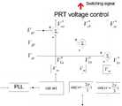
도 9는 본 발명에 따른 도 1의 전압제어기(140)가 3상으로 운전할 때의 동작 원리를 설명하기 위한 제어기 블록선도이다.FIG. 9 is a controller block diagram illustrating an operating principle when the
이의 기본적인 동작 원리는 도 1의 전압제어기(140)와 같다. 따라서 전압제어기는 적정 조도를 유지하면서 전력절감을 극대화 할 수 있는 최적의 조명전압(VL(abc))[실제 VL은 각 상에 관계없이 같다.]을 설정하고 이를 인입 계통전압(Vg(abc))의 크기에 관계없이 일정하게 유지 공급하기 위하여 전압제어기(140)에 의 하여 제2 인버터(160)의 전압 지령치 V*x(abc)를 산정한다. 수학식 5에 의하여 산정된 각 상의 V*x(abc)는 도 9에서와 같이 PRT 전압 제어기에 의하여 제2 인버터(120)를 제어한다. 여기서 PRT 전압 제어기는 인버터를 전압제어형으로 제어하는 PWM(Pulse Width Modulation)기법으로, 이 방법은 이미 알려진 기술로서, 본 발명의 핵심 요지가 아니므로 상세한 설명은 생략한다.Its basic operation principle is the same as the
본 발명에 따른 계통 연계형 태양광 발전시스템이 3상 계통에 적용되는 경우, 본 발명의 고안의도에 따라 동작할 수 있음을 확인하기 위하여 PSIM 시뮬레이션한 결과를 도 10에 보였다.When the grid-tied photovoltaic power generation system according to the present invention is applied to a three-phase grid, PSIM simulation results are shown in FIG.
도 10은 본 발명에 따른 계통 연계형 태양광 발전시스템이 3상 계통에 적용 되었을 때, 3상 계통 인입 전압이 불평형이고, 심지어 한 상은 비선형전압이며, 부하 역시 비선형 불평형 부하가 인가되었을 경우의 시스템 동작을 시뮬레이션한 결과 파형이다. 시뮬레이션에 사용된 모든 소자는 이상적인 것으로 가정하여 PSIM 소프트웨어를 이용하여 시뮬레이션을 수행하였다.10 is a system when a three-phase grid inlet voltage is unbalanced, even one phase is a non-linear voltage when the grid-connected photovoltaic power generation system according to the present invention is applied to a three-phase grid, and the load is also applied with a non-linear unbalanced load. The waveform is the result of simulating the motion. All the devices used in the simulation were assumed to be ideal, and the simulation was performed using PSIM software.
도 10은 위에서부터 순서대로 3상 인입 계통전압(Vg-a, Vg-b, Vg-c), 3상 부하 전압(VL-a, VL-b, VL-c), 3상 계통전류(Ig-a, Ig-b, Ig-c), 3상 부하 전류(IL-a, IL-b, IL-c)의 파형이다. 이는 본 발명에 따른 계통 연계형 태양광 발전시스템이 3상 계통에 적용되는 경우, 3상 계통 인입 전압이 불평형이고, 심지어 한 상은 비선형전압이 며, 부하 역시 비선형 불평형 부하와 같은 혹독한 조건의 상황에서도 본 발명의 고안 의도대로 3상 계통전류를 평형화 함은 물론 역율 및 고조파 등의 전력품질을 개선하고, 3상 부하 전압 역시 전력품질개선과 함께 평형화 시킬 수 있음을 보여 주는 것이다. 따라서 고안된 시스템은 절전 기능은 물론이고, 비선형 부하를 포함한 모든 3상 부하 또는 3상 전압 조건에서도 단상과 마찬가지로 MPPT 제어를 통해 태양전지의 최대전력을 얻음과 동시에 역률개선 및 고조파 저감 그리고 3상 평형화 제어성능이 매우 우수함을 알 수 있다.10 is a three-phase incoming grid voltage (Vg-a , Vg-b , Vg-c ), three-phase load voltage (VL-a , VL-b , VL-c ) in order from the top, three-phase grid current is a waveform of (Ig-a,-b Ig, Ig-c), the three-phase load current(I L -a, I L -b , I L -c). This is because when the grid-connected photovoltaic power generation system according to the present invention is applied to a three-phase grid, the three-phase grid inlet voltage is unbalanced, even one phase is a nonlinear voltage, and the load is also in a severe condition such as a nonlinear unbalanced load. As the intention of the present invention is to balance the three-phase system current as well as to improve the power quality such as power factor and harmonics, and to show that the three-phase load voltage can also be balanced with the power quality improvement. Therefore, the designed system can achieve the maximum power of the solar cell through MPPT control as well as power saving, harmonic reduction, and three-phase equilibration control, as well as power saving function, as well as single-phase under all three-phase load or three-phase voltage conditions including non-linear load. It can be seen that the performance is very good.
도 1은 본 발명에 따른 계통 연계형 태양광 발전시스템의 일 실시예의 구성을 나타낸 구성도이다.1 is a configuration diagram showing the configuration of an embodiment of a grid-tied photovoltaic power generation system according to the present invention.
도 2는 본 발명에 따른 도 1의 MPPT-PQC 통합 제어기(130) 동작 원리를 설명하기 위한 제어기 블록선도이다.2 is a controller block diagram illustrating an operation principle of the MPPT-PQC
도 3은 본 발명에 따른 계통 연계형 태양광 발전시스템의 야간모드 시 MPPT-PQC 통합 제어기(130)의 동작에 따른 시뮬레이션 결과 파형이다.3 is a simulation result waveform according to the operation of the MPPT-PQC
도 4는 본 발명에 따른 계통 연계형 태양광 발전시스템의 주간모드 시 MPPT-PQC 통합 제어기(130)의 동작에 따른 시뮬레이션 결과 파형이다.Figure 4 is a simulation result waveform according to the operation of the MPPT-PQC
도 5는 본 발명에 따른 계통 연계형 태양광 발전시스템의 조명부하 전압제어에 의한 에너지 절감 효과를 확인하기 위하여, 비선형 부하에 240V, 50Hz의 입력전압을 인가했을 때의 시뮬레이션 결과 파형이다.5 is a simulation result waveform when the input voltage of 240V, 50Hz to the non-linear load in order to confirm the energy saving effect by the lighting load voltage control of the grid-tied photovoltaic power generation system according to the present invention.
도 6은 본 발명에 따른 계통 연계형 태양광 발전시스템의 조명부하 전압제어에 의한 에너지 절감 효과를 확인하기 위하여, 비선형 부하에 210V, 50Hz의 입력전압을 인가했을 때의 시뮬레이션 결과 파형이다.6 is a simulation result waveform when applying the input voltage of 210V, 50Hz to the non-linear load in order to confirm the energy saving effect by the lighting load voltage control of the grid-tied photovoltaic power generation system according to the present invention.
도 7은 본 발명에 따른 계통 연계형 태양광 발전시스템의 MPPT-PQC 통합 제어기(130)와 전압제어기(140)를 통해 제1 인버터(120)와 제2 인버터(160)를 동시에 운전했을 때의 시뮬레이션 결과 파형이다.FIG. 7 illustrates an operation of simultaneously operating the
도 8은 본 발명에 따른 도 1의 MPPT-PQC 통합 제어기(130)가 3상으로 운전할 때의 동작 원리를 설명하기 위한 제어기 블록선도이다.FIG. 8 is a controller block diagram illustrating an operation principle when the MPPT-PQC
도 9는 본 발명에 따른 도 1의 전압제어기(140)가 3상으로 운전할 때의 동작 원리를 설명하기 위한 제어기 블록선도이다.FIG. 9 is a controller block diagram illustrating an operating principle when the
도 10은 본 발명에 따른 계통 연계형 태양광 발전시스템이 3상 계통에 적용 되었을 때의 시뮬레이션 결과 파형이다.10 is a waveform of simulation results when the grid-tied photovoltaic power generation system according to the present invention is applied to a three-phase grid.
Claims (5)
Translated fromKoreanPriority Applications (3)
| Application Number | Priority Date | Filing Date | Title |
|---|---|---|---|
| KR1020080050783AKR100993108B1 (en) | 2008-05-30 | 2008-05-30 | Grid-connected photovoltaic power generation system with improved power quality and power saving |
| PCT/KR2008/003263WO2009145380A1 (en) | 2008-05-30 | 2008-06-11 | A grid-interactive photovoltaic generation system with power quality control and energy saving |
| US12/991,595US8880229B2 (en) | 2008-05-30 | 2008-06-11 | Grid-interactive photovoltaic generation system with power quality control and energy saving |
Applications Claiming Priority (1)
| Application Number | Priority Date | Filing Date | Title |
|---|---|---|---|
| KR1020080050783AKR100993108B1 (en) | 2008-05-30 | 2008-05-30 | Grid-connected photovoltaic power generation system with improved power quality and power saving |
Publications (2)
| Publication Number | Publication Date |
|---|---|
| KR20090124515A KR20090124515A (en) | 2009-12-03 |
| KR100993108B1true KR100993108B1 (en) | 2010-11-08 |
Family
ID=41377237
Family Applications (1)
| Application Number | Title | Priority Date | Filing Date |
|---|---|---|---|
| KR1020080050783AExpired - Fee RelatedKR100993108B1 (en) | 2008-05-30 | 2008-05-30 | Grid-connected photovoltaic power generation system with improved power quality and power saving |
Country Status (3)
| Country | Link |
|---|---|
| US (1) | US8880229B2 (en) |
| KR (1) | KR100993108B1 (en) |
| WO (1) | WO2009145380A1 (en) |
Cited By (1)
| Publication number | Priority date | Publication date | Assignee | Title |
|---|---|---|---|---|
| CN102324865A (en)* | 2011-09-23 | 2012-01-18 | 武汉新能源接入装备与技术研究院有限公司 | Method for controlling three-phase current transformer in photovoltaic grid-connected power generating system |
Families Citing this family (79)
| Publication number | Priority date | Publication date | Assignee | Title |
|---|---|---|---|---|
| US9325173B2 (en)* | 2009-09-15 | 2016-04-26 | The University Of Western Ontario | Utilization of distributed generator inverters as STATCOM |
| US20240014653A1 (en)* | 2009-09-15 | 2024-01-11 | Rajiv Kumar Varma | Utilization of distributed generator inverters as statcom |
| US11784496B2 (en)* | 2009-09-15 | 2023-10-10 | Rajiv Kumar Varma | Utilization of distributed generator inverters as STATCOM |
| KR101119128B1 (en)* | 2010-01-22 | 2012-03-20 | 동산엔지니어링 주식회사 | Power supply apparatus for light rail transit using utility interactive photovoltaic generation |
| KR101128377B1 (en)* | 2010-05-25 | 2012-03-23 | 고은순 | A electrical energy saver with improved power quality |
| CN101888095A (en)* | 2010-07-19 | 2010-11-17 | 西安理工大学 | Variable structure control method for photovoltaic grid-connected power generation system |
| CN101950983A (en)* | 2010-10-08 | 2011-01-19 | 天津理工大学 | Two-stage photovoltaic grid-connected control system based on combination of pole allocation and repetitive control |
| JPWO2012050208A1 (en)* | 2010-10-15 | 2014-02-24 | 三洋電機株式会社 | Power management system |
| DE102010048866A1 (en)* | 2010-10-19 | 2012-04-19 | Armin Weigl | Electronic three-phase current supply transformer for use in industries for power supply, has control electronic circuit, where electronic flux converter enables energy transmission from three-phase network at three-phase voltage |
| CN101980436B (en)* | 2010-10-27 | 2012-08-22 | 南京航空航天大学 | Grid-connected photovoltaic inverter device and control method for improving conversion efficiency thereof |
| CN101976852A (en)* | 2010-11-02 | 2011-02-16 | 深圳市合兴加能科技有限公司 | Photovoltaic power supply system structure and method thereof |
| CN101980409B (en)* | 2010-11-25 | 2013-06-19 | 河北工业大学 | Grid-connected photovoltaic inverter |
| KR101032487B1 (en)* | 2011-03-07 | 2011-04-29 | 파워에너텍 주식회사 | Solar Power Control Device |
| CN102299525B (en)* | 2011-09-08 | 2013-12-11 | 天津理工大学 | Hybrid control device for grid-connected photovoltaic power generating system and control method of hybrid control device |
| CN102522766B (en)* | 2011-11-04 | 2014-12-24 | 浙江昱能科技有限公司 | Flyback type miniature photovoltaic grid connected inverter with power decoupling circuit and control method thereof |
| CN103138287A (en)* | 2011-12-05 | 2013-06-05 | 上海航天有线电厂 | Three phase inverter used for solar photovoltaic grid-connected system |
| KR101379749B1 (en)* | 2012-01-20 | 2014-03-31 | 청주대학교 산학협력단 | Power supply and method in energy system |
| CN102593862B (en)* | 2012-02-02 | 2014-11-05 | 广西师范大学 | Photovoltaic grid-connected inverter and control method thereof |
| CN102646977B (en)* | 2012-04-20 | 2014-12-17 | 苏州英诺华微电子有限公司 | Secondary booster circuit for boosting voltage based on MPPT (maximum power point tracking) and distributed solar battery pack |
| CN102723732A (en)* | 2012-06-21 | 2012-10-10 | 上海市电力公司 | A distributed photovoltaic grid-connected power generation system |
| CN103515974B (en)* | 2012-06-28 | 2016-05-25 | 周德佳 | The single-phase grid-connected control method of photovoltaic of the two MPPT functions of a kind of efficient stable |
| CN102769302B (en)* | 2012-07-10 | 2015-05-20 | 江苏辉伦太阳能科技有限公司 | Photovoltaic grid-connected inverter with stored energy management and load-power-based output functions |
| CN102751741B (en)* | 2012-07-13 | 2015-02-25 | 浙江埃菲生能源科技有限公司 | Low-voltage ride through (LVRT) control system of photovoltaic inverter and method thereof |
| CN102832642B (en)* | 2012-09-12 | 2014-06-11 | 湖南大学 | Control method of quality control system of micro source internetworking electric energy |
| CN103001248A (en)* | 2012-11-14 | 2013-03-27 | 华北电力大学 | Modularity-based megawatt-level photovoltaic power generation simulation system and application thereof |
| CN103094922B (en)* | 2013-01-11 | 2015-06-24 | 西安理工大学 | Two-level type single-phase grid-connected photovoltaic power generation control method |
| US9728964B2 (en) | 2013-03-15 | 2017-08-08 | Vivint, Inc. | Power production monitoring or control |
| CN103269086B (en)* | 2013-04-24 | 2014-12-10 | 西安理工大学 | Positive and negative sequence component separation method of low-voltage ride-through control of photovoltaic grid-connected inverter |
| CN103219747B (en)* | 2013-04-28 | 2015-05-27 | 南京工业大学 | Method for realizing high efficiency and high reliability of photovoltaic grid-connected micro inverter |
| CN103326622A (en)* | 2013-06-19 | 2013-09-25 | 国家电网公司 | Photovoltaic system suitable for high-voltage direct-current transmission |
| CN103414203B (en)* | 2013-06-27 | 2015-10-28 | 广西师范大学 | Based on photovoltaic generation island detection method and the device of Liapunov exponent change |
| ES2535059B1 (en)* | 2013-10-31 | 2016-02-09 | Control Techniques Iberia S.A. | Method and system to control a power supply to a load |
| CN103580030B (en)* | 2013-11-26 | 2015-11-18 | 重庆大学 | Parallel networking type photovoltaic power station reactive voltage control method and system |
| CN104734177B (en)* | 2013-12-24 | 2017-04-05 | 珠海格力电器股份有限公司 | Grid-connected connection equipment, control method thereof and grid-connected power supply system |
| CN103779874B (en)* | 2014-01-16 | 2016-01-06 | 南京航空航天大学 | The non-isolated grid-connected electricity generation system of single-stage boost inverter and control method thereof |
| DE112014006204T5 (en)* | 2014-02-13 | 2016-11-03 | Hitachi, Ltd. | Performance Exchange Management System and Performance Exchange Management Procedures |
| CN103812118A (en)* | 2014-02-26 | 2014-05-21 | 上海交通大学 | Front feed type non-series-transformer voltage drop compensation device based on wind electricity |
| CN103812117A (en)* | 2014-02-26 | 2014-05-21 | 上海交通大学 | Feed-forward voltage compensation device based on solar photovoltaic power generation |
| CN103825300B (en)* | 2014-03-12 | 2015-09-30 | 浙江埃菲生能源科技有限公司 | A kind of line voltage phase-lock technique passed through for photovoltaic combining inverter no-voltage |
| TWI514746B (en) | 2014-04-03 | 2015-12-21 | Ind Tech Res Inst | Energy voltage regulator and control method applicable thereto |
| CN103972924B (en)* | 2014-04-16 | 2017-04-05 | 国网上海市电力公司 | Permanent magnet direct-drive wind power system low voltage traversing control method under unbalanced electric grid voltage |
| CN104158169B (en)* | 2014-05-16 | 2016-04-06 | 湖南工业大学 | A kind of photovoltaic DC microgrid busbar voltage control method |
| CN104007349A (en)* | 2014-06-11 | 2014-08-27 | 江苏大学 | Fuzzy control island detection method based on wavelet transformation |
| US10879695B2 (en) | 2014-07-04 | 2020-12-29 | Apparent Labs, LLC | Grid network gateway aggregation |
| US11063431B2 (en) | 2014-07-04 | 2021-07-13 | Apparent Labs Llc | Hierarchical and distributed power grid control |
| US20160087433A1 (en) | 2014-07-04 | 2016-03-24 | Stefan Matan | Data aggregation with operation forecasts for a distributed grid node |
| CN104124711A (en)* | 2014-08-12 | 2014-10-29 | 无锡上能新能源有限公司 | Solar photovoltaic power generation system |
| TWI533579B (en) | 2014-10-01 | 2016-05-11 | 財團法人工業技術研究院 | Output power adjusting method for inverter |
| WO2016070882A1 (en)* | 2014-11-03 | 2016-05-12 | Vestas Wind Systems A/S | Method of controlling active power generation of a wind power plant and wind power plant |
| CN104485687B (en)* | 2014-11-27 | 2016-09-14 | 浙江工业大学 | PI resonance control method for photovoltaic grid-connected inverter based on switching between continuous current mode and discontinuous current mode |
| CN104467016B (en)* | 2014-12-18 | 2017-07-28 | 阳光电源股份有限公司 | A kind of five level photovoltaic inverter precharge control methods and system |
| US9543859B2 (en) | 2015-01-23 | 2017-01-10 | Suzan EREN | System and method for active/reactive power compensation |
| CN104753045A (en)* | 2015-04-15 | 2015-07-01 | 国家电网公司 | Distributed photovoltaic grid-connection safeguard system |
| CN104901336B (en)* | 2015-06-09 | 2017-09-08 | 新疆希望电子有限公司 | The reference output current generation method of photovoltaic combining inverter in the case of a kind of dim light |
| KR20170029199A (en) | 2015-09-07 | 2017-03-15 | 강문수 | Photovoltaic Power Generation Apparatus |
| CN105048508B (en)* | 2015-09-08 | 2017-08-25 | 苏州大学 | A kind of control method and system of T-shaped tri-level single phase combining inverter |
| CN105226930B (en)* | 2015-09-23 | 2018-04-13 | 北京能高自动化技术股份有限公司 | A kind of reactive power control method applied to grid-connected current transformer |
| CN105322564A (en)* | 2015-10-22 | 2016-02-10 | 国家电网公司 | Wind-solar integrated power generation system capable of automatically achieving voltage balance |
| CN105404734B (en)* | 2015-11-09 | 2019-01-11 | 广东电网有限责任公司珠海供电局 | The recognition methods and system of ferro-resonance over-voltage type |
| CN105356469A (en)* | 2015-11-19 | 2016-02-24 | 福州大学 | Uniform control method based on harmonic detection and photovoltaic grid-connected instruction synthesis |
| CN105375522B (en)* | 2015-11-30 | 2017-10-27 | 河海大学常州校区 | A kind of photovoltaic combining inverter control method |
| CN105654036A (en)* | 2015-12-18 | 2016-06-08 | 广东电网有限责任公司珠海供电局 | Nonlinear characteristic quantity detection method and system |
| CN105406516B (en)* | 2015-12-30 | 2018-10-02 | 阳光电源股份有限公司 | Anti- PID devices, anti-PID grid-connected photovoltaic systems and anti-PID approach |
| CN106026170B (en)* | 2016-06-28 | 2018-08-10 | 天津科林电气有限公司 | A kind of control method adjusting photovoltaic combining inverter input power according to network voltage |
| CN106602605B (en)* | 2017-01-03 | 2024-05-03 | 珠海格力电器股份有限公司 | Maximum power point tracking control system of photovoltaic array and photovoltaic air conditioning system |
| CN108828459A (en)* | 2018-08-17 | 2018-11-16 | 国网冀北电力有限公司张家口供电公司 | A kind of photovoltaic generation power output slip measuring device and its estimation method |
| CN109494788B (en) | 2018-11-08 | 2020-09-29 | 珠海格力电器股份有限公司 | Photovoltaic electrical appliance system and voltage protection value control method and device thereof |
| KR102218748B1 (en)* | 2019-02-13 | 2021-02-23 | 한국전력공사 | Operation method of reactive power compensation device |
| CN112436551B (en)* | 2020-11-17 | 2023-03-28 | 上海海事大学 | Ship power supply system |
| CN112904930B (en)* | 2021-01-21 | 2022-03-25 | 山东大学 | Maximum power point tracking control method of medium-voltage photovoltaic power generation system |
| CN114123351B (en)* | 2021-11-26 | 2024-07-26 | 锦浪科技股份有限公司 | Grid-off control method for key load of grid-off energy storage inverter capable of being combined |
| CN114221386A (en)* | 2021-12-24 | 2022-03-22 | 佛山索弗克氢能源有限公司 | 500kVA light, wind, diesel, hydrogen, electricity and energy storage multifunctional complementary power supply device and power supply method thereof |
| CN114899883A (en)* | 2022-05-20 | 2022-08-12 | 厦门科华数能科技有限公司 | Control method, terminal and power supply system of photovoltaic-based dual power supply system |
| PL245373B1 (en)* | 2022-06-25 | 2024-07-08 | Mmb Drives Spolka Z Ograniczona Odpowiedzialnoscia | Method and system of voltage regulation and phase load symmetrization of a three-phase power line |
| WO2024001202A1 (en)* | 2022-06-27 | 2024-01-04 | 云南电网有限责任公司电力科学研究院 | Unbalanced current regulation system and method for capacity increasing and split-phase output of distribution transformer |
| KR20240006257A (en)* | 2022-07-06 | 2024-01-15 | 엘에스일렉트릭(주) | Reactive Power Compensation Device |
| US20240388120A1 (en)* | 2023-05-19 | 2024-11-21 | Electric Outdoors, Inc. | Portable, solar-powered campsite system for charging and powering electric and recreational vehicles |
| KR20250119281A (en) | 2024-01-31 | 2025-08-07 | (주)신정개발 | Power quality control system using multi-agent reinforcement learning |
| CN118336719B (en)* | 2024-06-12 | 2024-09-17 | 徐州太一世纪能源科技有限公司 | Stability analysis method, equipment and storage medium for photovoltaic power generation system |
Citations (1)
| Publication number | Priority date | Publication date | Assignee | Title |
|---|---|---|---|---|
| WO2003084041A1 (en)* | 2002-03-28 | 2003-10-09 | Curtin University Of Technology | Power conversion system and method of converting power |
Family Cites Families (45)
| Publication number | Priority date | Publication date | Assignee | Title |
|---|---|---|---|---|
| SE377412B (en) | 1973-10-23 | 1975-06-30 | Asea Ab | |
| EP1020973A3 (en) | 1999-01-18 | 2001-05-02 | Hitachi, Ltd. | A charge and discharge system for electric power storage equipment |
| US6281485B1 (en)* | 2000-09-27 | 2001-08-28 | The Aerospace Corporation | Maximum power tracking solar power system |
| US6433522B1 (en)* | 2001-05-02 | 2002-08-13 | The Aerospace Corporation | Fault tolerant maximum power tracking solar power system |
| ITVA20010022A1 (en)* | 2001-07-11 | 2003-01-11 | Chemieco Srl | STATIC VOLTAGE INVERTER FOR BATTERY SYSTEM |
| JP4545443B2 (en) | 2002-03-28 | 2010-09-15 | コーゲン・マイクロシステムズ・ピーティーワイ・リミテッド | Reciprocating engine and its intake system |
| JP2004079997A (en)* | 2002-06-19 | 2004-03-11 | Canon Inc | Power generation system and power generation apparatus |
| US7463500B2 (en)* | 2003-02-21 | 2008-12-09 | Xantrex Technology, Inc. | Monopolar DC to bipolar DC to AC converter |
| US6914418B2 (en)* | 2003-04-21 | 2005-07-05 | Phoenixtec Power Co., Ltd. | Multi-mode renewable power converter system |
| WO2004100344A2 (en)* | 2003-05-02 | 2004-11-18 | Ballard Power Systems Corporation | Method and apparatus for tracking maximum power point for inverters in photovoltaic applications |
| US7269036B2 (en)* | 2003-05-12 | 2007-09-11 | Siemens Vdo Automotive Corporation | Method and apparatus for adjusting wakeup time in electrical power converter systems and transformer isolation |
| WO2004107543A2 (en)* | 2003-05-28 | 2004-12-09 | Beacon Power Corporation | Power converter for a solar panel |
| JP2005312138A (en)* | 2004-04-19 | 2005-11-04 | Canon Inc | Power controller, power generation system and power system |
| US7248946B2 (en)* | 2004-05-11 | 2007-07-24 | Advanced Energy Conversion, Llc | Inverter control methodology for distributed generation sources connected to a utility grid |
| US7193872B2 (en)* | 2005-01-28 | 2007-03-20 | Kasemsan Siri | Solar array inverter with maximum power tracking |
| ITSA20050014A1 (en)* | 2005-07-13 | 2007-01-14 | Univ Degli Studi Salerno | SINGLE STAGE INVERTER DEVICE, AND ITS CONTROL METHOD, FOR POWER CONVERTERS FROM ENERGY SOURCES, IN PARTICULAR PHOTOVOLTAIC SOURCES. |
| US7952897B2 (en)* | 2005-12-22 | 2011-05-31 | Power-One Italy S.P.A. | System for producing electric power from renewable sources and a control method thereof |
| US8405367B2 (en)* | 2006-01-13 | 2013-03-26 | Enecsys Limited | Power conditioning units |
| GB2434490B (en)* | 2006-01-13 | 2009-04-01 | Enecsys Ltd | Power conditioning unit |
| KR100809443B1 (en)* | 2006-07-26 | 2008-03-07 | 창원대학교 산학협력단 | Controller of Single Phase Power Converter for Solar Power System |
| US8013472B2 (en)* | 2006-12-06 | 2011-09-06 | Solaredge, Ltd. | Method for distributed power harvesting using DC power sources |
| US8618692B2 (en)* | 2007-12-04 | 2013-12-31 | Solaredge Technologies Ltd. | Distributed power system using direct current power sources |
| US8816535B2 (en)* | 2007-10-10 | 2014-08-26 | Solaredge Technologies, Ltd. | System and method for protection during inverter shutdown in distributed power installations |
| US7994657B2 (en)* | 2006-12-22 | 2011-08-09 | Solarbridge Technologies, Inc. | Modular system for unattended energy generation and storage |
| US9031874B2 (en)* | 2007-01-12 | 2015-05-12 | Clean Power Finance, Inc. | Methods, systems and agreements for increasing the likelihood of repayments under a financing agreement for renewable energy equipment |
| US20120143383A1 (en)* | 2007-02-02 | 2012-06-07 | Inovus Solar, Inc. | Energy-efficient utility system utilizing solar-power |
| US7772716B2 (en)* | 2007-03-27 | 2010-08-10 | Newdoll Enterprises Llc | Distributed maximum power point tracking system, structure and process |
| US8158877B2 (en)* | 2007-03-30 | 2012-04-17 | Sunpower Corporation | Localized power point optimizer for solar cell installations |
| US8624439B2 (en)* | 2007-06-06 | 2014-01-07 | Power-One Italy S.P.A. | Delivery of electric power by means of a plurality of parallel inverters and control method based on maximum power point tracking |
| KR100886194B1 (en)* | 2007-06-08 | 2009-02-27 | 한국전기연구원 | On-grid high-voltage winding induction generator control unit |
| US7834580B2 (en)* | 2007-07-27 | 2010-11-16 | American Power Conversion Corporation | Solar powered apparatus |
| US8203069B2 (en)* | 2007-08-03 | 2012-06-19 | Advanced Energy Industries, Inc | System, method, and apparatus for coupling photovoltaic arrays |
| US7945413B2 (en)* | 2007-09-04 | 2011-05-17 | Solarbridge Technologies, Inc. | Voltage-sensed system and method for anti-islanding protection of grid-connected inverters |
| US20090078300A1 (en)* | 2007-09-11 | 2009-03-26 | Efficient Solar Power System, Inc. | Distributed maximum power point tracking converter |
| US7755916B2 (en)* | 2007-10-11 | 2010-07-13 | Solarbridge Technologies, Inc. | Methods for minimizing double-frequency ripple power in single-phase power conditioners |
| CA2737134C (en)* | 2007-10-15 | 2017-10-10 | Ampt, Llc | Systems for highly efficient solar power |
| WO2009073867A1 (en)* | 2007-12-05 | 2009-06-11 | Solaredge, Ltd. | Parallel connected inverters |
| US8625315B2 (en)* | 2008-05-09 | 2014-01-07 | Etm Electromatic Inc | Inverter modulator with variable switching frequency |
| US8139382B2 (en)* | 2008-05-14 | 2012-03-20 | National Semiconductor Corporation | System and method for integrating local maximum power point tracking into an energy generating system having centralized maximum power point tracking |
| US7768155B2 (en)* | 2008-10-10 | 2010-08-03 | Enphase Energy, Inc. | Method and apparatus for improved burst mode during power conversion |
| CA2655007C (en)* | 2009-02-20 | 2017-06-27 | Queen's University At Kingston | Photovoltaic cell inverter |
| US8159178B2 (en)* | 2009-08-21 | 2012-04-17 | Xantrex Technology Inc. | AC connected modules with line frequency or voltage variation pattern for energy control |
| US9325173B2 (en)* | 2009-09-15 | 2016-04-26 | The University Of Western Ontario | Utilization of distributed generator inverters as STATCOM |
| US8462518B2 (en)* | 2009-10-12 | 2013-06-11 | Solarbridge Technologies, Inc. | Power inverter docking system for photovoltaic modules |
| US8406022B2 (en)* | 2010-04-16 | 2013-03-26 | Samsung Electro-Mechanics Co., Ltd. | Apparatus and method for controling power quality of power generation system |
- 2008
- 2008-05-30KRKR1020080050783Apatent/KR100993108B1/ennot_activeExpired - Fee Related
- 2008-06-11USUS12/991,595patent/US8880229B2/ennot_activeExpired - Fee Related
- 2008-06-11WOPCT/KR2008/003263patent/WO2009145380A1/enactiveApplication Filing
Patent Citations (1)
| Publication number | Priority date | Publication date | Assignee | Title |
|---|---|---|---|---|
| WO2003084041A1 (en)* | 2002-03-28 | 2003-10-09 | Curtin University Of Technology | Power conversion system and method of converting power |
Cited By (1)
| Publication number | Priority date | Publication date | Assignee | Title |
|---|---|---|---|---|
| CN102324865A (en)* | 2011-09-23 | 2012-01-18 | 武汉新能源接入装备与技术研究院有限公司 | Method for controlling three-phase current transformer in photovoltaic grid-connected power generating system |
Also Published As
| Publication number | Publication date |
|---|---|
| KR20090124515A (en) | 2009-12-03 |
| US8880229B2 (en) | 2014-11-04 |
| WO2009145380A1 (en) | 2009-12-03 |
| US20110088748A1 (en) | 2011-04-21 |
Similar Documents
| Publication | Publication Date | Title |
|---|---|---|
| KR100993108B1 (en) | Grid-connected photovoltaic power generation system with improved power quality and power saving | |
| Lakshmi et al. | Coordinated control of MPPT and voltage regulation using single-stage high gain DC–DC converter in a grid-connected PV system | |
| CN105207258B (en) | A photovoltaic DC microgrid energy coordination control device | |
| Tsengenes et al. | Investigation of the behavior of a three phase grid-connected photovoltaic system to control active and reactive power | |
| Kyritsis et al. | Enhanced current pulsation smoothing parallel active filter for single stage grid-connected AC-PV modules | |
| Hamouda et al. | Predictive control of a grid connected PV system incorporating active power filter functionalities | |
| Rachid et al. | Application of an active power filter on photovoltaic power generation system | |
| Abdel-Salam et al. | Design, implementation and operation of a stand-alone residential photovoltaic system | |
| Modi et al. | A maximum correntropy criteria based adaptive algorithm for an improved power quality SPV system | |
| Chaudhary et al. | Hybrid control approach for PV/FC fed voltage source converter tied to grid | |
| Rudraram et al. | PV Integrated UPQC with Intelligent Control Techniques for Power Quality Enhancement | |
| KR101281079B1 (en) | Photoelectric cell system with improved power quality and operating method of it | |
| Balamurugan et al. | Solar PV Based Shunt Active Filter with p-q Theory Control for Improvement of Power Quality | |
| Müller et al. | Ultracapacitor storage enabled global MPPT for photovoltaic central inverters | |
| CN104104104A (en) | Method of automatic switching between power generation mode and SVG mode for photovoltaic inverter | |
| Shukla | Control and operation of multifunctional NPC inverter for Grid-connected solar PV | |
| CN106026136B (en) | A kind of method for controlling power balance for access device of powering | |
| CN203399048U (en) | An optical electrical complementation AC frequency-variable generating and speed-regulating energy-saving device | |
| Kumar et al. | Unity power factor control of grid connected SPV system using instantaneous symmetrical component theory | |
| Baharudin et al. | Control of a multi-functional grid-connected solar PV system using instantaneous reactive power (PQ) theory for current harmonic alleviations | |
| Patel et al. | PV Based Distributed Generation with Compensation Feature Under Unbalanced and Non-linear Load Conditions for a 3-ϕ, 4 Wire System | |
| Barbosa et al. | Analysis of a single-phase hybrid bidirectional rectifier with series voltage compensation in a grid-connected DC microgrid | |
| Pham | Direct storage hybrid (DSH) inverter: A new concept of intelligent hybrid inverter | |
| Verma et al. | Grid connected single phase rooftop PV system with limited reactive power supply | |
| Hao et al. | Study and Simulation of Grid-connected Photovoltaic System Based on Interleaved Boost Converter and H-bridge Inverter with Low Current Ripple |
Legal Events
| Date | Code | Title | Description |
|---|---|---|---|
| A201 | Request for examination | ||
| PA0109 | Patent application | St.27 status event code:A-0-1-A10-A12-nap-PA0109 | |
| PA0201 | Request for examination | St.27 status event code:A-1-2-D10-D11-exm-PA0201 | |
| R18-X000 | Changes to party contact information recorded | St.27 status event code:A-3-3-R10-R18-oth-X000 | |
| PG1501 | Laying open of application | St.27 status event code:A-1-1-Q10-Q12-nap-PG1501 | |
| E902 | Notification of reason for refusal | ||
| PE0902 | Notice of grounds for rejection | St.27 status event code:A-1-2-D10-D21-exm-PE0902 | |
| E13-X000 | Pre-grant limitation requested | St.27 status event code:A-2-3-E10-E13-lim-X000 | |
| P11-X000 | Amendment of application requested | St.27 status event code:A-2-2-P10-P11-nap-X000 | |
| P13-X000 | Application amended | St.27 status event code:A-2-2-P10-P13-nap-X000 | |
| E701 | Decision to grant or registration of patent right | ||
| PE0701 | Decision of registration | St.27 status event code:A-1-2-D10-D22-exm-PE0701 | |
| GRNT | Written decision to grant | ||
| PR0701 | Registration of establishment | St.27 status event code:A-2-4-F10-F11-exm-PR0701 | |
| PR1002 | Payment of registration fee | St.27 status event code:A-2-2-U10-U11-oth-PR1002 Fee payment year number:1 | |
| PG1601 | Publication of registration | St.27 status event code:A-4-4-Q10-Q13-nap-PG1601 | |
| PN2301 | Change of applicant | St.27 status event code:A-5-5-R10-R13-asn-PN2301 St.27 status event code:A-5-5-R10-R11-asn-PN2301 | |
| FPAY | Annual fee payment | Payment date:20131101 Year of fee payment:4 | |
| PR1001 | Payment of annual fee | St.27 status event code:A-4-4-U10-U11-oth-PR1001 Fee payment year number:4 | |
| PN2301 | Change of applicant | St.27 status event code:A-5-5-R10-R11-asn-PN2301 | |
| PN2301 | Change of applicant | St.27 status event code:A-5-5-R10-R14-asn-PN2301 | |
| PC1903 | Unpaid annual fee | St.27 status event code:A-4-4-U10-U13-oth-PC1903 Not in force date:20141103 Payment event data comment text:Termination Category : DEFAULT_OF_REGISTRATION_FEE | |
| FPAY | Annual fee payment | Payment date:20150617 Year of fee payment:5 | |
| K11-X000 | Ip right revival requested | St.27 status event code:A-6-4-K10-K11-oth-X000 | |
| PC1903 | Unpaid annual fee | St.27 status event code:N-4-6-H10-H13-oth-PC1903 Ip right cessation event data comment text:Termination Category : DEFAULT_OF_REGISTRATION_FEE Not in force date:20141103 | |
| PR0401 | Registration of restoration | St.27 status event code:A-6-4-K10-K13-oth-PR0401 | |
| R401 | Registration of restoration | ||
| PR1001 | Payment of annual fee | St.27 status event code:A-4-4-U10-U11-oth-PR1001 Fee payment year number:5 | |
| PN2301 | Change of applicant | St.27 status event code:A-5-5-R10-R11-asn-PN2301 | |
| PN2301 | Change of applicant | St.27 status event code:A-5-5-R10-R14-asn-PN2301 | |
| FPAY | Annual fee payment | Payment date:20151007 Year of fee payment:6 | |
| PR1001 | Payment of annual fee | St.27 status event code:A-4-4-U10-U11-oth-PR1001 Fee payment year number:6 | |
| R18-X000 | Changes to party contact information recorded | St.27 status event code:A-5-5-R10-R18-oth-X000 | |
| FPAY | Annual fee payment | Payment date:20161025 Year of fee payment:7 | |
| PR1001 | Payment of annual fee | St.27 status event code:A-4-4-U10-U11-oth-PR1001 Fee payment year number:7 | |
| FPAY | Annual fee payment | Payment date:20170927 Year of fee payment:8 | |
| PR1001 | Payment of annual fee | St.27 status event code:A-4-4-U10-U11-oth-PR1001 Fee payment year number:8 | |
| P14-X000 | Amendment of ip right document requested | St.27 status event code:A-5-5-P10-P14-nap-X000 | |
| FPAY | Annual fee payment | Payment date:20181022 Year of fee payment:9 | |
| PR1001 | Payment of annual fee | St.27 status event code:A-4-4-U10-U11-oth-PR1001 Fee payment year number:9 | |
| PN2301 | Change of applicant | St.27 status event code:A-5-5-R10-R11-asn-PN2301 | |
| PN2301 | Change of applicant | St.27 status event code:A-5-5-R10-R14-asn-PN2301 | |
| R18-X000 | Changes to party contact information recorded | St.27 status event code:A-5-5-R10-R18-oth-X000 | |
| P14-X000 | Amendment of ip right document requested | St.27 status event code:A-5-5-P10-P14-nap-X000 | |
| FPAY | Annual fee payment | Payment date:20190826 Year of fee payment:10 | |
| PR1001 | Payment of annual fee | St.27 status event code:A-4-4-U10-U11-oth-PR1001 Fee payment year number:10 | |
| R18-X000 | Changes to party contact information recorded | St.27 status event code:A-5-5-R10-R18-oth-X000 | |
| PR1001 | Payment of annual fee | St.27 status event code:A-4-4-U10-U11-oth-PR1001 Fee payment year number:11 | |
| PR1001 | Payment of annual fee | St.27 status event code:A-4-4-U10-U11-oth-PR1001 Fee payment year number:12 | |
| R18-X000 | Changes to party contact information recorded | St.27 status event code:A-5-5-R10-R18-oth-X000 | |
| PR1001 | Payment of annual fee | St.27 status event code:A-4-4-U10-U11-oth-PR1001 Fee payment year number:13 | |
| R18-X000 | Changes to party contact information recorded | St.27 status event code:A-5-5-R10-R18-oth-X000 | |
| PN2301 | Change of applicant | St.27 status event code:A-5-5-R10-R13-asn-PN2301 St.27 status event code:A-5-5-R10-R11-asn-PN2301 | |
| PN2301 | Change of applicant | St.27 status event code:A-5-5-R10-R13-asn-PN2301 St.27 status event code:A-5-5-R10-R11-asn-PN2301 | |
| R18-X000 | Changes to party contact information recorded | St.27 status event code:A-5-5-R10-R18-oth-X000 | |
| PR1001 | Payment of annual fee | St.27 status event code:A-4-4-U10-U11-oth-PR1001 Fee payment year number:14 | |
| PR1001 | Payment of annual fee | St.27 status event code:A-4-4-U10-U11-oth-PR1001 Fee payment year number:15 | |
| PR1001 | Payment of annual fee | St.27 status event code:A-4-4-U10-U11-oth-PR1001 Fee payment year number:16 |