KR100987590B1 - Image stabilization control circuit and imaging device equipped with it - Google Patents
Image stabilization control circuit and imaging device equipped with itDownload PDFInfo
- Publication number
- KR100987590B1 KR100987590B1KR1020080128950AKR20080128950AKR100987590B1KR 100987590 B1KR100987590 B1KR 100987590B1KR 1020080128950 AKR1020080128950 AKR 1020080128950AKR 20080128950 AKR20080128950 AKR 20080128950AKR 100987590 B1KR100987590 B1KR 100987590B1
- Authority
- KR
- South Korea
- Prior art keywords
- image
- signal
- mode
- optical
- imaging device
- Prior art date
- Legal status (The legal status is an assumption and is not a legal conclusion. Google has not performed a legal analysis and makes no representation as to the accuracy of the status listed.)
- Expired - Fee Related
Links
Images


Classifications
- H—ELECTRICITY
- H04—ELECTRIC COMMUNICATION TECHNIQUE
- H04N—PICTORIAL COMMUNICATION, e.g. TELEVISION
- H04N23/00—Cameras or camera modules comprising electronic image sensors; Control thereof
- H04N23/60—Control of cameras or camera modules
- H04N23/68—Control of cameras or camera modules for stable pick-up of the scene, e.g. compensating for camera body vibrations
- H04N23/681—Motion detection
- H04N23/6812—Motion detection based on additional sensors, e.g. acceleration sensors
- H—ELECTRICITY
- H04—ELECTRIC COMMUNICATION TECHNIQUE
- H04N—PICTORIAL COMMUNICATION, e.g. TELEVISION
- H04N23/00—Cameras or camera modules comprising electronic image sensors; Control thereof
- H04N23/60—Control of cameras or camera modules
- H04N23/68—Control of cameras or camera modules for stable pick-up of the scene, e.g. compensating for camera body vibrations
- H04N23/682—Vibration or motion blur correction
- H04N23/683—Vibration or motion blur correction performed by a processor, e.g. controlling the readout of an image memory
- H—ELECTRICITY
- H04—ELECTRIC COMMUNICATION TECHNIQUE
- H04N—PICTORIAL COMMUNICATION, e.g. TELEVISION
- H04N23/00—Cameras or camera modules comprising electronic image sensors; Control thereof
- H04N23/60—Control of cameras or camera modules
- H04N23/68—Control of cameras or camera modules for stable pick-up of the scene, e.g. compensating for camera body vibrations
- H04N23/682—Vibration or motion blur correction
- H04N23/684—Vibration or motion blur correction performed by controlling the image sensor readout, e.g. by controlling the integration time
- H04N23/6842—Vibration or motion blur correction performed by controlling the image sensor readout, e.g. by controlling the integration time by controlling the scanning position, e.g. windowing
Landscapes
- Engineering & Computer Science (AREA)
- Multimedia (AREA)
- Signal Processing (AREA)
- Studio Devices (AREA)
- Adjustment Of Camera Lenses (AREA)
Abstract
Translated fromKoreanDescription
Translated fromKorean본 발명은 손떨림 등의 진동을 보정하는 기능을 탑재하는 손떨림 보정 제어 회로 및 그것을 탑재한 촬상 장치에 관한 것이다.BACKGROUND OF THE INVENTION 1. Field of the Invention The present invention relates to a camera shake correction control circuit having a function of correcting vibration such as camera shake, and an imaging device mounted therewith.
디지털 스틸 카메라나 디지털 무비 카메라(이하, 총칭하여 단순히 디지털 카메라라고 표기한다)가 일반 사용자에게도 널리 보급되어 왔다. 카메라의 취급에 익숙하지 않은 사용자는 촬영 시에 손떨림을 일으키기 쉬워, 그것을 보정하기 위해 다양한 방법이 제안되고 있다. 디지털 카메라 중에는 휴대 전화기의 한 기능으로서 탑재되는 것이나, 한손으로 쥐고 촬영하는 스타일의 것도 있다. 이러한, 한쪽 손의 엄지 손가락을 사용하여 촬영하는 스타일의 기기에서는 양 손으로 촬영하는 일반적인 스타일의 카메라 이상으로 손떨림이 발생하기 쉽다는 경향이 있다.Digital still cameras and digital movie cameras (hereinafter collectively simply referred to as digital cameras) have been widely used by general users. Users unfamiliar with the handling of cameras are liable to cause camera shake during shooting, and various methods have been proposed to correct them. Some digital cameras are mounted as a function of a mobile phone, and some are held in one hand. In such a style of photographing using the thumb of one hand, there is a tendency that hand shake is more likely to occur than a general style camera photographing with both hands.
이와 같은 손떨림을 보정하기 위한 방법으로서, 예를 들어 광학식 손떨림 보정 및 전자식 손떨림 보정이 실용화되고 있다. 광학식 손떨림 보정은 카메라의 진동을 검출하는 진동 검출 소자와, 그 진동에 의한 흔들림을 상쇄하는 방향으로 렌즈의 위치를 작동시키는 구동 소자에 의해 광축을 보정하는 방법이다. 전자식 손 떨림 보정은 동화상에 있어서의 인접하는 프레임 화상간에서, 특징점 등을 검출함으로써 화상간의 움직임을 특정하여 그 움직임을 상쇄하도록 촬상 영역에 있어서의 잘라내기 위치를 변화시키는 방법이다.As a method for correcting such a camera shake, for example, optical camera shake correction and electronic camera shake correction have been put into practical use. Optical image stabilization is a method of correcting an optical axis by a vibration detection element that detects vibration of a camera and a drive element that operates the position of the lens in a direction to cancel the shake caused by the vibration. Electronic image stabilization is a method of changing the cutting position in the imaging area so as to specify a motion between images by canceling the motion by detecting feature points or the like between adjacent frame images in a moving image.
<특허 문헌1> 일본 특개평10-213832호 공보Patent Document 1: Japanese Patent Application Laid-Open No. 10-213832
광학식 손떨림 보정은 1프레임 화상만으로 보정이 가능하다는 이점이 있다. 이 점, 전자식 손떨림 보정은 움직임을 검출하기 위하여 복수의 프레임 화상이 필요하며, 1프레임 화상 내에 발생한 손떨림은 보정할 수 없다. 단, 광학식 손떨림 보정은 렌즈의 위치를 보정하기 위한 기계적인 구동 기구가 필요하여 소비 전력의 문제가 있다.Optical image stabilization has an advantage that correction is possible with only one frame image. In this respect, the electronic image stabilization requires a plurality of frame images in order to detect motion, and image stabilization generated in one frame image cannot be corrected. However, optical image stabilization requires a mechanical drive mechanism for correcting the position of the lens, which causes a problem in power consumption.
전자식 손떨림 보정은 광학식 손떨림 보정과 비교하여 소비 전력이 적어도 된다는 이점이 있다. 단, 보정이 프레임 레이트에 의존한다는 문제가 있다. 프레임 레이트가 낮은 경우, 정밀도가 높은 보정이 어려워진다.Electronic image stabilization has an advantage that power consumption is reduced as compared with optical image stabilization. However, there is a problem that the correction depends on the frame rate. When the frame rate is low, high precision correction becomes difficult.
이와 같이 광학식 손떨림 보정과 전자식 손떨림 보정은 트레이드 오프의 관계에 있다.As described above, the optical image stabilization and the electronic image stabilization are in a trade-off relationship.
본 발명은 이러한 상황을 감안하여 이루어진 것으로, 그 목적은 손떨림 등의 진동을 고정밀도이면서 저소비 전력으로 보정할 수 있는 손떨림 보정 제어 회로 및 그것을 탑재한 촬상 장치를 제공하는 것에 있다.This invention is made | formed in view of such a situation, and the objective is to provide the shake correction control circuit which can correct | amend vibrations, such as a shake, with high precision and low power consumption, and the imaging device equipped with it.
본 발명의 임의의 형태의 손떨림 보정 제어 회로는 진동 검출 소자의 출력 신호에 따라 광축을 보정하는 광학식 손떨림 보정부와, 촬상 소자에 의해 형성되는 촬상 영역의 화상 신호 중 유효 영역을 적절하게 변화시키는 전자식 손떨림 보정부와, 제1 촬상 모드와 제2 촬상 모드를 절환하는 제어부를 구비하고, 제어부는 제1 촬상 모드와 제2 촬상 모드의 절환에 의해 광학식 손떨림 보정부와 전자식 손떨림 보정부 중 유효하게 하는 것을 변화시키도록 제어한다.An image stabilization control circuit of any aspect of the present invention includes an optical image stabilization unit for correcting an optical axis in accordance with an output signal of a vibration detection element, and an electronic type for appropriately changing an effective area of an image signal of an imaging area formed by the imaging element. And a control unit for switching the first image pickup mode and the second image pickup mode, wherein the control unit is configured to enable the optical image stabilizer and the electronic image stabilizer to be effective by switching between the first image pickup mode and the second image pickup mode. Control to change things.
본 발명에 따르면, 손떨림 등의 진동을 고정밀도이면서 저소비 전력으로 보정할 수 있다.According to the present invention, vibrations such as hand shake can be corrected with high precision and low power consumption.
도1은 본 발명의 실시 형태에 따른 촬상 장치(500)의 구성을 도시하는 블록도이다. 촬상 장치(500)는 렌즈(60), 구동 소자(80), 위치 검출 소자(70), 진동 검출 소자(50), 광학식 손떨림 보정부(20), 촬상 소자(100), 화상 처리부(200), 표시부(300) 및 조작부(400)를 구비한다.1 is a block diagram showing a configuration of an
구동 소자(80)는 렌즈(60)를 구동한다. 위치 검출 소자(70)는 렌즈(60)의 위치를 검출한다. 진동 검출 소자(50)는 촬상 장치(500)에 가해지는 진동을 검출한다.The
광학식 손떨림 보정부(20)는 진동 검출 소자(50)의 출력 신호에 따라 구동 소자(80)를 제어함으로써 렌즈(60)의 위치를 보정한다. 구동 소자(80)를 제어하기 위한 신호로서, 진동 검출 소자(50)의 출력 신호에 따라 촬상 장치(500)의 이동량 을 구하여 그 이동량을 보정하기 위한 신호를 생성할 수 있다. 이 신호를, 후술하는 제어부(220)로 공급할 수도 있다. 광학식 손떨림 보정부(20)의 상세한 구성은 후술한다.The optical image stabilizer 20 corrects the position of the
촬상 소자(100)는 렌즈(60)를 투과한 광신호를 전기 신호로 변환한다. CCD 센서 또는 CMOS 이미지 센서를 채용할 수 있다.The
화상 처리부(200)는 촬상 소자(100)로부터 출력되는 화상 신호를 처리한다. 보다 구체적인 구성으로서, 화상 처리부(200)는 신호 처리부(210) 및 제어부(220)를 포함한다. 이들 구성은 하드웨어적으로는 임의의 컴퓨터의 CPU, 메모리, 그 밖의 LSI로 실현할 수 있고, 소프트웨어적으로는 메모리에 로드된 화상 처리 프로그램 등에 의해 실현되나, 여기에서는 그들의 연휴에 의해 실현되는 기능 블록을 도시하고 있다. 따라서, 이들 기능 블록이 하드웨어만으로, 소프트웨어만으로, 또는 그들의 조합에 의해 다양한 형태로 실현할 수 있는 것은 당업자에게는 이해되는 점이다.The
제어부(220)는 신호 처리부(210)에 대하여, 촬상 소자(100)에 의해 형성되는 촬상 영역의 화상 신호 중 유효로 해야 할 영역의 화상 신호를 잘라내도록 제어한다. 전자식 손떨림 보정을 사용할 경우, 화상으로서 표시 또는 기록해야 할 유효 화소수보다 많은 화소수를 갖는 촬상 영역이 형성된다. 상술한, 유효로 해야 할 영역의 화상 신호를 잘라낸다는 것은, 실제로 촬상된 화상 신호 중 채용하는 영역의 화상 신호를 유효로 하고, 채용하지 않은 영역의 화상 신호를 무효로 하는 처리이어도 좋다. 또한, 촬상 영역을 형성하는 복수의 촬상 소자 중 채용하는 영역의 촬상 소자를 유효로 하고, 채용하지 않는 영역의 촬상 소자를 무효로 하는 처리이어도 좋다.The
제어부(220)는 촬상 모드를 절환한다. 예를 들어, 동영상 촬상 모드와 정지 화상 촬상 모드의 경우가 있다. 이들 모드는 조작부(400)로부터 사용자 조작에 기인하여 지정될 수 있다. 예를 들어, 초기 상태에서 동영상 촬상 모드였던 것이 조작부(400)에 포함되는 정지 화상용의 셔터 버튼을 누르면 정지 화상 촬상 모드로 지정된다. 또한, 정지 화상 촬상 모드에는 연사 모드가 포함되어도 좋다. 또한, 동영상 촬상 모드란 실제로 기록하기 위해 동영상을 촬상하는 경우라도 좋고, 기록을 목적으로 하지 않고 정지 화상의 촬상에 앞서 프리뷰를 표시부(300)에 표시하는 경우이어도 좋다. 또한, 촬상 모드의 절환은 기록을 목적으로 하지 않는 동영상 촬상 모드로부터 기록을 목적으로 하는 동영상 촬상 모드로의 절환이어도 좋다. 요컨대, 제1 촬상 모드와 이와는 다른 제2 촬상 모드로의 절환이면 된다.The
예를 들어, 제어부(220)는 동영상 촬상 모드일 때 렌즈(60)의 위치의 보정 처리를 무효화하고, 또한 유효 영역을 적절하게 변화시키도록 제어하고, 정지 화상 촬상 모드일 때 신호 처리부(210)가 유효 영역을 고정하고, 또한 구동 소자(80) 및 광학식 손떨림 보정부(20)에 의한 상기 보정 처리를 유효화하도록 제어한다. 즉, 동영상 촬상 모드일 때 전자식 손떨림 보정을 사용하고, 정지 화상 촬상 모드일 때 광학식 손떨림 보정을 사용한다.For example, the
신호 처리부(210)는 동영상 촬상 모드일 때 광학식 손떨림 보정부(20)로부터 촬상 장치(500)의 이동량을 보정하기 위한 신호를 받아, 그 신호에 기초하여 잘라 내야 할 영역을 변화시킬 수 있다. 즉, 그 이동량을 상쇄하도록 유효 영역을 반대 방향으로 이동시킨다. 또한, 촬상 장치(500)의 이동량은 광학식 손떨림 보정부(20)로부터 취득하는 방법에 한정하는 것은 아니며, 인접하는 화상간에서 특징점 등을 추적함으로써 추정해도 좋다.The
표시부(300)는 신호 처리부(210)에 의해 잘라내어진 화상 신호에 기초하여 화상을 표시한다. 제어부(220)는 정지 화상 촬상 모드에 앞서, 동영상 촬상 모드로 촬상된 동영상을 프리뷰로서 표시부(300)에 표시시키도록 제어할 수도 있다.The
제어부(220)는 정지 화상 촬상 모드로부터 동영상 촬상 모드로 절환될 때, 촬상 영역에 있어서의 유효 영역을 중앙으로 이동시킨다. 상술한 바와 같이 동영상 촬상 모드에서는 촬상 영역에 있어서 유효 영역을 적절하게 이동시키기 때문에 상기 절환 시에 유효 영역을 초기 처리로서 중앙으로 이동시키는 처리를 실행하는 편이 낫다. 이에 의해, 동영상 촬상의 재개 시에 보정 범위가 가장 넓은 위치로 초기화된다.The
도2는 실시 형태에 따른 광학식 손떨림 보정부(20)의 구성을 도시하는 블록도이다.2 is a block diagram showing the configuration of the
광학식 손떨림 보정부(20)는 제1 이퀄라이저(24), 제2 이퀄라이저(40), ADC(22) 및 DAC(46)를 갖는다.The
제1 이퀄라이저(24)는 HPF(26), 팬 틸트 판정 회로(28), 게인 조정 회로(30), 적분 회로(32), 센터링 처리 회로(34) 및 게인 조정 회로(36)를 포함한다. 제2 이퀄라이저(40)는 가산 회로(42) 및 서보 회로(44)를 포함한다.The
이하, 광학식 손떨림 보정부(20)의 구성 및 동작을 더 구체적으로 설명한다.Hereinafter, the configuration and operation of the
전제로서, 진동 검출 소자(50)는 자이로 센서(50a)를 채용할 수 있다. 이하, 자이로 센서(50a)를 채용하는 예로 설명한다. 이하, 자이로 센서(50a)는 촬상 장치(500)를 갖는 사용자의 손떨림에 의한 가속도를 각속도로 하여 검출하는 것으로 한다. 위치 검출 소자(70)는 홀 소자(70a)를 채용할 수 있다. 이하, 홀 소자(70a)를 채용하는 예로 설명한다. 구동 소자(80)는 보이스 코일 모터(VCM)(80a)를 채용할 수 있다. 이하, VCM(80a)를 채용하는 예로 설명한다.As a premise, the
자이로 센서(50a)는 촬상 장치(500)의 XY의 2축 방향의 각속도를 검출한다. 자이로 센서에 의해 얻어진 아날로그의 각속도 신호는 도시하지 않은 증폭 회로에 의해 증폭된 후, ADC(아날로그 디지털 컨버터)(22)로 출력된다. ADC(22)는 당해 증폭 회로에 의해 증폭된 각속도 신호를 디지털의 각속도 신호로 변환한다. ADC(22)로부터 출력된 각속도 신호는 제1 이퀄라이저(24)로 출력된다.The gyro sensor 50a detects the angular velocity of XY biaxial direction of the
제1 이퀄라이저(24)에 있어서, 우선 ADC(22)로부터 출력된 디지털의 각속도 신호가 HPF(하이 패스 필터)(26)에 입력된다. HPF(26)는 자이로 센서(50a)로부터 출력된 각속도 신호 중 손떨림에 의한 주파수 성분보다 낮은 주파수 성분을 제거한다. 일반적으로, 손떨림에 의한 주파수 성분은 1 내지 20㎐이기 때문에, 예를 들어 각속도 신호로부터 0.7Hz 이하의 주파수 성분이 제거된다.In the
팬 틸트 판정 회로(28)는 HPF(26)가 출력하는 각속도 신호에 기초하여 촬상 장치(500)의 팬 동작, 틸트 동작을 검출한다. 팬 틸트 판정 회로(28)는 일정 기간 연속하여 각속도 신호가 소정값 이상이 되는 것을 검출했을 때에 팬 동작 중 또는 틸트 동작 중이라고 판정한다. 또한, 피사체의 이동 등에 따라 촬상 장치(500)를 수평 방향으로 작동하도록 하는 것을 팬 동작이라고 하고, 수직 방향으로 이동시키는 것을 틸트 동작이라고 한다.The pan
게인 조정 회로(30)는 팬 틸트 판정 회로(28)의 판정 결과에 따라 HPF(26)로부터 출력되는 각속도 신호의 증폭율을 변경한다. 예를 들어, 팬 동작 중 또는 틸트 동작 중이 아닌 경우에는 게인 조정 회로(30)는 HPF(26)가 출력하는 각속도 신호의 강도를 유지하는 게인 조정을 행한다. 또한, 팬 동작 중 또는 틸트 동작 중인 경우에는 게인 조정 회로(30)는 HPF(26)가 출력하는 각속도 신호의 강도를 감쇠시켜 출력이 0이 되는 게인 조정을 행한다.The
적분 회로(32)는 게인 조정 회로(30)가 출력한 각속도 신호를 적분하여 촬상 장치(500)의 이동량을 나타내는 진동 성분 신호를 생성한다. 예를 들어, 적분 회로(32)는 도시하지 않은 디지털 필터를 포함하여 구성하는 것이 적합하고, 도시하지 않은 레지스터에 설정된 필터 계수에 따른 필터 처리를 행함으로써 각도 신호, 즉 촬상 장치(500)의 이동량을 구한다.The integrating
촬상 장치(500)에 있어서 손떨림 보정 처리를 행하는 경우, 보정 처리를 계속하여 실행하는 동안에 렌즈(60)의 위치가 기준 위치로부터 서서히 멀어져 가, 렌즈(60)의 가동 범위의 한계점 부근에 도달하는 경우가 있다. 이때, 손떨림 보정 처리를 계속하면 렌즈(60)는 어느 한 쪽의 방향으로는 이동할 수 있으나, 다른 쪽으로는 이동할 수 없게 된다. 센터링 처리 회로(34)는 이것을 방지하기 위하여 설치되는 것이다.In the
센터링 처리 회로(34)로부터 출력된 진동 성분 신호는 게인 조정 회로(36)에 의해 홀 소자(70a)의 출력 신호의 범위로 조정된다. 게인 조정 회로(36)에 의해 조정된 진동 성분 신호는 제2 이퀄라이저(40)로 출력된다.The vibration component signal output from the centering
홀 소자(70a)는 홀 효과를 이용한 자기 센서이며, 렌즈(60)의 X 및 Y 방향의 위치 검출 소자로서 기능한다. 홀 소자(70a)에 의해 얻어진 렌즈(60)의 위치 정보를 포함하는 아날로그의 위치 신호는 도시하지 않은 증폭 회로에 의해 증폭된 후, ADC(22)로 출력된다. ADC(22)는 당해 증폭 회로에 의해 증폭된 아날로그의 위치 신호를 디지털의 위치 신호로 변환한다. 또한, ADC(22)는 상기 아날로그의 각속도 신호 및 상기 아날로그의 위치 신호를 시분할에 의해 디지털의 신호로 변환한다.The hall element 70a is a magnetic sensor using the Hall effect, and functions as a position detecting element in the X and Y directions of the
ADC(22)로부터 출력된 위치 신호는 제2 이퀄라이저(40)로 출력된다. 제2 이퀄라이저(40)에 있어서, 우선 ADC(22)로부터 출력된 위치 신호는 가산 회로(42)에 입력된다. 또한, 가산 회로(42)에는 게인 조정 회로(36)에 의해 조정된 진동 성분 신호가 입력된다. 가산 회로(42)는 입력된 위치 신호와 진동 성분 신호를 가산한다. 가산 회로(42)로부터 출력된 신호는 서보 회로(44)로 출력된다. 서보 회로(44)는 가산 회로(42)로부터의 출력 신호에 따라 VCM(80a)의 구동을 제어하는 신호를 생성한다. 또한, 서보 회로(44)에 있어서, 서보 제어용의 디지털 필터를 사용한 필터 처리가 이루어져도 좋다.The position signal output from the
서보 회로(44)로부터 출력된 VCM 구동 신호는, DAC(디지털 아날로그 컨버터)(46)에 의해 디지털 신호로부터 아날로그 신호로 변환된다. 아날로그의 VCM 구동 신호는 도시하지 않은 증폭 회로에 의해 증폭된 후, VCM(80a)으로 출력된다. VCM(80a)은 VCM 구동 신호에 기초하여 렌즈(60)의 X 및 Y 방향의 위치를 이동시킨다.The VCM drive signal output from the
여기서 손떨림이 없는 경우와 손떨림이 있는 경우의 본 실시 형태의 촬상 장치(500)의 동작에 대하여 설명한다.Here, the operation of the
(손떨림이 없는 경우의 동작)(Operation without camera shake)
손떨림이 없는 경우에는 촬상 장치(500)에 각속도가 발생하지 않기 때문에 제1 이퀄라이저(24)가 출력하는 신호는 "0"이 된다. VCM(80a)에 의해 구동되는 렌즈(60)의 위치는, 그 광축과 촬상 장치(500)에 구비되는 촬상 소자(100)의 중심이 일치하기 때문에 홀 소자(70a)로부터의 아날로그의 위치 신호는 ADC(22)에 의해 "0"을 나타내는 디지털의 위치 신호로 변환된 후, 제2 이퀄라이저(40)로 출력된다. 따라서, 서보 회로(44)는 현재의 렌즈(60)의 위치를 유지하도록 VCM(80a)을 제어하는 신호를 출력한다.In the absence of camera shake, since no angular velocity occurs in the
또한, 렌즈(60)의 광축과 촬상 소자(100)의 중심이 일치하지 않는 경우, 홀 소자(70a)로부터의 아날로그의 위치 신호는 ADC(22)에 의해 "0"과 다른 값을 나타내는 디지털의 위치 신호로 변환된 후, 제2 이퀄라이저(40)로 출력된다. 서보 회로(44)는 ADC(22)가 출력하는 디지털의 위치 신호의 값에 따라 위치 신호의 값이 "0"이 되도록 VCM(80a)을 제어한다.In addition, when the optical axis of the
이와 같은 동작을 반복함으로써 렌즈(60)의 광축과 촬상 소자(100)의 중심이 일치하도록 렌즈(60)의 위치가 제어된다.By repeating such an operation, the position of the
(손떨림이 있는 경우의 동작)(Operation when there is camera shake)
VCM(80a)에 의해 구동되는 렌즈(60)의 위치는 그 광축과 촬상 소자(100)의 중심이 일치하기 때문에 홀 소자(70a)로부터의 아날로그의 위치 신호는 ADC(22)에 의해 "0"을 나타내는 디지털의 위치 신호로 변환된 후, 제2 이퀄라이저(40)로 출력된다.Since the position of the
한편, 손떨림에 의해 촬상 장치(500)가 이동하기 때문에 적분 회로(32) 및 센터링 처리 회로(34)는 자이로 센서(50a)에 의해 검출된 각속도 신호에 기초하여 촬상 장치(500)의 이동량을 나타내는 진동 성분 신호를 출력한다.On the other hand, since the
서보 회로(44)는 ADC(22)가 출력하는 "0"을 나타내는 위치 신호와, 센터링 처리 회로(34)가 출력하는 진동 성분 신호를 가산한 신호에 따라 VCM(80a)의 구동 신호를 생성한다. 이때, 위치 신호는 "0"임에도 불구하고, "0"이 아닌 진동 성분 신호가 가산되어 있기 때문에 서보 회로(44)는 렌즈(60)를 이동시키는 보정 신호를 생성한다.The
또한, 본 실시 형태의 손떨림 보정은 촬상 소자로부터 출력되는 화상 신호를 한번 메모리에 읽어들여, 다음 화상과의 비교로부터 손떨림의 요소를 배제하는, 소위 전자식 손떨림 보정이 아니라, 전술한 바와 같이 렌즈를 광학적으로 시프트시키는 렌즈 시프트 방식 등과 같은 광학식 손떨림 보정이다.In addition, the image stabilization according to the present embodiment is not so-called electronic image stabilization, which reads an image signal output from an image pickup device into a memory once and excludes an element of image stabilization from a comparison with the next image. Optical image stabilization, such as a lens shift method for shifting by a second direction.
따라서, 전자식 손떨림 보정 기구를 채용한 경우에 발생하는 과제, 즉 미리 크게 취한 화상을 트리밍하는 것에 기인하는 화질의 저하나, CCD 사이즈 등의 촬상 소자 사이즈의 제약에 의한 보정 범위나 촬상 배율의 한계가 있는 것, 또한 1컷 1컷의 정지 화상의 흔들림을 보정할 수 없다는 과제를 광학식 손떨림 보정은 해결할 수 있다는 효과를 갖는다. 특히, 고화질 비디오의 영상으로부터 정지 화상을 취출하는 경우에는 광학식 손떨림 보정이 유효하다.Therefore, the problem that arises when the electronic image stabilization mechanism is adopted, that is, the limitation of the correction range and the imaging magnification due to the reduction in the image quality caused by trimming the previously taken image or the limitation of the image pickup element such as the CCD size is limited. There is an effect that the optical image stabilization solves the problem that there is a problem that the shake of the still image of one cut and one cut cannot be corrected. In particular, optical image stabilization is effective when taking out a still image from a video of a high quality video.
서보 회로(44)가 출력하는 보정 신호에 기초하여 VCM(80a)은 렌즈(60)를 이동시키기 때문에 촬상 소자(100)는 손떨림에 의한 피사체의 흔들림을 억제한 신호를 얻을 수 있다. 이러한 제어를 반복함으로써 손떨림 보정 제어가 실현된다.Since the VCM 80a moves the
도3은 실시 형태에 따른 정지 화상 촬상 모드에 있어서의 촬상 영역(600)과 유효 영역(700)을 도시하는 도면이다. 정지 화상 촬상 모드에서는 신호 처리부(210)로부터 표시부(300) 또는 도시하지 않은 인코더 등으로 출력되는 화상 신호의 유효 영역(700)은 동영상 촬상 모드로부터 정지 화상 촬상 모드로 절환될 때의 최후 동화상의 유효 영역을 출력시키는 것이 적합하다. 즉, 이 모드에서는 광학식 손떨림 보정을 행한다. 이에 의해, 동화상과 정지 화상 사이에서 유효 영역의 어긋남이 발생하기 어렵다.3 is a diagram showing an
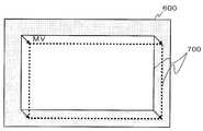
도4는 실시 형태에 따른 동영상 촬상 모드에 있어서의 촬상 영역(600)과 유효 영역(700)을 도시하는 도면이다. 동영상 촬상 모드에서는 광학식 손떨림 보정부(20)로부터 공급되는 촬상 장치(500)의 이동량 정보[도4에서는 움직임 벡터(MV)로서 도시되어 있다]에 기초하여 신호 처리부(210)로부터 출력되는 화상 신호의 유효 영역(700)을 적절하게 변경한다. 즉, 이 모드에서는 전자식 손떨림 보정을 행한다.4 is a diagram showing an
이상 설명한 바와 같이 본 실시 형태에 따르면, 동영상 촬상 모드에서는 전자식 보정을 사용하고, 정지 화상 모드에서는 광학식 보정을 사용함으로써 손떨림 등의 진동을 고정밀도이면서 저소비 전력으로 보정할 수 있다. 또한, 전자식 보정을 할 때, 광학식 손떨림 보정부(20)에 의해 해석된 이동량 정보를 사용함으로써 화상 처리에 따른 연산량을 저감시킬 수 있다. 즉, 화상간의 특징점 등을 비교하여 움직임을 추정하기 위한 연산을 생략할 수 있다.As described above, according to the present embodiment, by using the electronic correction in the moving image pick-up mode and the optical correction in the still image mode, vibrations such as hand shake can be corrected with high precision and low power consumption. In addition, when the electronic correction is performed, the amount of calculation according to image processing can be reduced by using the movement amount information analyzed by the
특히, 본 실시 형태는 정지 화상 촬상 전의 프리뷰에 적용하는 것이 유효하다. 전자식 보정은 정밀도를 충분히 확보할 수 없을 때가 있으나, 프리뷰용의 보정으로서는 충분하며, 구동 소자(80)를 사용하지 않는 것에 의한 소비 전력 저감의 이점이 더 크다.In particular, it is effective to apply this embodiment to the preview before a still image pick-up. Although the electronic correction may not be able to sufficiently secure the precision, the correction for the preview is sufficient, and the advantage of reducing the power consumption by not using the
이상, 본 발명을 몇개의 실시 형태를 바탕으로 설명했다. 이 실시 형태는 예시이며, 그들 각 구성 요소나 각 처리 프로세스의 조합에 여러 변형예가 가능한 것, 또한 그러한 변형예도 본 발명의 범위에 있는 것은 당업자에게 이해되는 점이다.In the above, this invention was demonstrated based on some embodiment. This embodiment is an illustration, It is understood by those skilled in the art that various modifications are possible for each of these component and the combination of each processing process, and that such a modification is also in the scope of the present invention.
또한,이상의 실시 형태에서는 진동 검출 소자(50), 위치 검출 소자(70) 및 구동 소자(80)는 각각 자이로 센서, 홀 소자 및 보이스 코일 모터로 했으나, 본 발명은 거기에 한정되는 것이 아니다. 예를 들어, 진동 검출 소자(50)는 직선 방향의 가속도를 검출하는 센서를 사용하여 가속도 신호에 기초하여 촬상 장치(500)의 진동을 검출하는 구성으로 할 수 있다. 또한, 구동 소자(80)는 피에조 소자나 스테핑 모터 등을 사용할 수 있다. 위치 검출 소자(70)는 MR 소자 또는 포토스크린 다이오드 등을 사용할 수 있다.In addition, although the
상술한 실시 형태에서는 동영상 촬상 모드로부터 정지 화상 촬상 모드로의 절환의 예를 설명했으나, 제1 촬상 모드로부터 이것과는 다른 제2 촬상 모드로의 절환 시에 전자식 손떨림 보정과 광학식 손떨림 보정을 절환하는 것이면 된다. 또한, 촬상 모드의 절환이 없는 경우에도 사용자의 선택에 의해 전자식 손떨림 보정과 광학식 손떨림 보정을 선택 가능한 구성으로 해도 된다. 또한, 전자식 손떨림 보정만 선택한 상태와, 광학식 손떨림 보정 및 전자식 손떨림 보정의 양자를 선택한 상태를 절환해도 좋다. 양자를 선택함으로써 손떨림 보정 정밀도를 더 향상시키는 것이 가능해진다.In the above-described embodiment, an example of switching from the moving image pick-up mode to the still image pick-up mode has been described. However, the electronic image stabilization and the optical image stabilization are switched at the time of switching from the first image pick-up mode to the second image pick-up mode different from this. You just need to In addition, even when the imaging mode is not switched, the electronic camera shake correction and the optical camera shake correction may be selected by the user's selection. In addition, you may switch between the state which selected only the electronic image stabilization, and the state which selected both the optical image stabilization and the electronic image stabilization. By selecting both, it becomes possible to further improve the camera shake correction accuracy.
도1은 본 발명의 실시 형태에 따른 촬상 장치의 구성을 도시하는 블록도.1 is a block diagram showing a configuration of an imaging device according to an embodiment of the present invention.
도2는 실시 형태에 따른 광학식 손떨림 보정부의 구성을 도시하는 블록도.2 is a block diagram showing a configuration of an optical image stabilizer according to an embodiment.
도3은 실시 형태에 따른 정지 화상 촬상 모드에 있어서의 촬상 영역과 유효 영역을 도시하는 도면.3 is a diagram showing an imaging area and an effective area in a still image imaging mode according to the embodiment;
도4는 실시 형태에 따른 동영상 촬상 모드에 있어서의 촬상 영역과 유효 영역을 도시하는 도면.4 is a diagram showing an image capturing area and an effective area in a video image capturing mode according to an embodiment;
<부호의 설명><Code description>
20 : 광학식 손떨림 보정부20: optical image stabilizer
22 : ADC22: ADC
24 : 제1 이퀄라이저24: first equalizer
26 : HPF26: HPF
28 : 팬 틸트 판정 회로28: pan tilt determination circuit
30 : 게인 조정 회로30: gain adjustment circuit
32 : 적분 회로32: integral circuit
34 : 센터링 처리 회로34: centering processing circuit
36 : 게인 조정 회로36: gain adjustment circuit
40 : 제2 이퀄라이저40: second equalizer
42 : 가산 회로42: addition circuit
44 : 서보 회로44: servo circuit
46 : DAC46: DAC
50 : 진동 검출 소자50: vibration detection element
60 : 렌즈60 lens
70 : 위치 검출 소자70: position detection element
80 : 구동 소자80 drive element
100 : 촬상 소자100: imaging device
200 : 화상 처리부200: image processing unit
210 : 신호 처리부210: signal processing unit
220 : 제어부220: control unit
300 : 표시부300: display unit
400 : 조작부400: control panel
500 : 촬상 장치500: imaging device
Claims (5)
Translated fromKoreanApplications Claiming Priority (2)
| Application Number | Priority Date | Filing Date | Title |
|---|---|---|---|
| JP2007327852AJP5259172B2 (en) | 2007-12-19 | 2007-12-19 | Camera shake correction control circuit and imaging apparatus equipped with the same |
| JPJP-P-2007-327852 | 2007-12-19 |
Publications (2)
| Publication Number | Publication Date |
|---|---|
| KR20090067060A KR20090067060A (en) | 2009-06-24 |
| KR100987590B1true KR100987590B1 (en) | 2010-10-12 |
Family
ID=40788119
Family Applications (1)
| Application Number | Title | Priority Date | Filing Date |
|---|---|---|---|
| KR1020080128950AExpired - Fee RelatedKR100987590B1 (en) | 2007-12-19 | 2008-12-18 | Image stabilization control circuit and imaging device equipped with it |
Country Status (3)
| Country | Link |
|---|---|
| US (1) | US8098286B2 (en) |
| JP (1) | JP5259172B2 (en) |
| KR (1) | KR100987590B1 (en) |
Families Citing this family (24)
| Publication number | Priority date | Publication date | Assignee | Title |
|---|---|---|---|---|
| JP2009044520A (en)* | 2007-08-09 | 2009-02-26 | Sanyo Electric Co Ltd | Anti-vibration control circuit |
| JP2011039295A (en)* | 2009-08-11 | 2011-02-24 | Nikon Corp | Shake correcting device and optical equipment |
| JP5419647B2 (en)* | 2009-11-16 | 2014-02-19 | キヤノン株式会社 | Image blur correction device, imaging device including the same, and method for controlling image blur correction device |
| JP5521518B2 (en)* | 2009-12-01 | 2014-06-18 | ソニー株式会社 | Imaging apparatus, imaging method, and program |
| KR101603213B1 (en)* | 2010-02-12 | 2016-03-14 | 한화테크윈 주식회사 | Method for correcting handshaking and digital photographing apparatus adopting the method |
| KR101710631B1 (en)* | 2010-12-23 | 2017-03-08 | 삼성전자주식회사 | Digital image photographing apparatus and method for controlling the same |
| JP5886623B2 (en)* | 2011-12-27 | 2016-03-16 | キヤノン株式会社 | Imaging apparatus and control method thereof |
| JP6004785B2 (en)* | 2012-06-29 | 2016-10-12 | キヤノン株式会社 | Imaging apparatus, optical apparatus, imaging system, and control method |
| JP6351321B2 (en)* | 2013-05-28 | 2018-07-04 | キヤノン株式会社 | Optical apparatus, control method therefor, and control program |
| JP6351247B2 (en)* | 2013-12-12 | 2018-07-04 | キヤノン株式会社 | Image shake correction apparatus, control method therefor, optical apparatus, and imaging apparatus |
| WO2016199731A1 (en)* | 2015-06-10 | 2016-12-15 | 株式会社ソニー・インタラクティブエンタテインメント | Head-mounted display, display control method, and program |
| KR102449354B1 (en) | 2016-02-04 | 2022-09-30 | 삼성전기주식회사 | Image stabilization module and camera module |
| JP6674701B2 (en) | 2016-09-28 | 2020-04-01 | ルネサスエレクトロニクス株式会社 | Image processing module and semiconductor system |
| KR102608782B1 (en) | 2016-12-30 | 2023-12-04 | 삼성전자주식회사 | Device and Method for Compensating Motion Effect of an Electronic Device in an Image |
| US10049260B1 (en)* | 2017-01-27 | 2018-08-14 | Banuba Limited | Computer systems and computer-implemented methods specialized in processing electronic image data |
| WO2018197947A1 (en)* | 2017-04-26 | 2018-11-01 | Hushchyn Yury | Subject stabilisation based on the precisely detected face position in the visual input and computer systems and computer-implemented methods for implementing thereof |
| JP2019106655A (en) | 2017-12-14 | 2019-06-27 | ルネサスエレクトロニクス株式会社 | Semiconductor device and electronic device |
| JP2019106656A (en) | 2017-12-14 | 2019-06-27 | ルネサスエレクトロニクス株式会社 | Semiconductor device and electronic device |
| JP7324284B2 (en)* | 2018-12-26 | 2023-08-09 | 華為技術有限公司 | Imaging device, camera shake correction device, imaging method, and camera shake correction method |
| JP7462759B2 (en)* | 2020-07-31 | 2024-04-05 | 富士フイルム株式会社 | Imaging device and method of operation thereof |
| KR20220160341A (en) | 2021-05-27 | 2022-12-06 | 삼성전자주식회사 | Electronic device that synchronizes lens driving information and images |
| CN114531533A (en)* | 2022-02-22 | 2022-05-24 | 中国科学院长春光学精密机械与物理研究所 | Sliding window type high-definition color camera |
| US11770612B1 (en) | 2022-05-24 | 2023-09-26 | Motorola Mobility Llc | Electronic devices and corresponding methods for performing image stabilization processes as a function of touch input type |
| US12067231B2 (en) | 2022-05-24 | 2024-08-20 | Motorola Mobility Llc | Electronic devices and corresponding methods for capturing image quantities as a function of touch input type |
Citations (2)
| Publication number | Priority date | Publication date | Assignee | Title |
|---|---|---|---|---|
| JPH07123317A (en)* | 1993-10-21 | 1995-05-12 | Canon Inc | Imaging device with anti-vibration function |
| JP2000224470A (en)* | 1999-02-02 | 2000-08-11 | Minolta Co Ltd | Camera system |
Family Cites Families (5)
| Publication number | Priority date | Publication date | Assignee | Title |
|---|---|---|---|---|
| JP3423564B2 (en) | 1997-01-28 | 2003-07-07 | キヤノン株式会社 | Optical equipment |
| JP2000069351A (en)* | 1998-08-24 | 2000-03-03 | Ricoh Co Ltd | Imaging device |
| JP3697129B2 (en)* | 2000-01-20 | 2005-09-21 | キヤノン株式会社 | Imaging device |
| JP4418317B2 (en)* | 2004-07-21 | 2010-02-17 | オリンパス株式会社 | Imaging device |
| JP2007327852A (en)* | 2006-06-08 | 2007-12-20 | Mikuni Corp | Thermocouple inspection method and inspection apparatus |
- 2007
- 2007-12-19JPJP2007327852Apatent/JP5259172B2/enactiveActive
- 2008
- 2008-12-18KRKR1020080128950Apatent/KR100987590B1/ennot_activeExpired - Fee Related
- 2008-12-19USUS12/340,181patent/US8098286B2/enactiveActive
Patent Citations (2)
| Publication number | Priority date | Publication date | Assignee | Title |
|---|---|---|---|---|
| JPH07123317A (en)* | 1993-10-21 | 1995-05-12 | Canon Inc | Imaging device with anti-vibration function |
| JP2000224470A (en)* | 1999-02-02 | 2000-08-11 | Minolta Co Ltd | Camera system |
Also Published As
| Publication number | Publication date |
|---|---|
| US20090160952A1 (en) | 2009-06-25 |
| US8098286B2 (en) | 2012-01-17 |
| JP2009152793A (en) | 2009-07-09 |
| KR20090067060A (en) | 2009-06-24 |
| JP5259172B2 (en) | 2013-08-07 |
Similar Documents
| Publication | Publication Date | Title |
|---|---|---|
| KR100987590B1 (en) | Image stabilization control circuit and imaging device equipped with it | |
| KR101528860B1 (en) | Method and apparatus for correcting a shakiness in digital photographing apparatus | |
| US8587673B2 (en) | Camera image stabilization | |
| US8767079B2 (en) | Image capture apparatus and control method thereof | |
| JP6478504B2 (en) | Imaging apparatus and control method thereof | |
| KR20110074670A (en) | Imaging Device and Control Method | |
| KR100996053B1 (en) | Imaging device provided with a dustproof control circuit and a dustproof control circuit | |
| US9811891B2 (en) | Image shake correction device, optical apparatus, imaging apparatus, and control method | |
| JP5155625B2 (en) | Image stabilizer for camera | |
| JP2012058545A (en) | Imaging device | |
| JP5138525B2 (en) | Image blur correction apparatus and image blur correction method | |
| JP6039212B2 (en) | Image blur correction apparatus, imaging apparatus, and image blur correction apparatus control method | |
| JP6173134B2 (en) | Image blur correction apparatus and control method thereof | |
| JP5699806B2 (en) | Imaging device | |
| JP5161513B2 (en) | Camera shake correction apparatus and method | |
| JP4200767B2 (en) | Blur correction device and camera | |
| JP4683268B2 (en) | Image blur correction device | |
| JP2006292969A (en) | Image blur correcting device | |
| JP2012013778A (en) | Imaging apparatus | |
| JP2009168938A (en) | Imaging device | |
| JP2000069353A (en) | Camera shake detection device and camera shake correction device | |
| JP2012163852A (en) | Shake correction device and optical apparatus | |
| JP3960140B2 (en) | Video camera | |
| JP6759019B2 (en) | Blur correction device and its control method, imaging device | |
| KR20100013170A (en) | Digital camera having warming function to limit for image stabilization and the controlling method thereof |
Legal Events
| Date | Code | Title | Description |
|---|---|---|---|
| A201 | Request for examination | ||
| PA0109 | Patent application | St.27 status event code:A-0-1-A10-A12-nap-PA0109 | |
| PA0201 | Request for examination | St.27 status event code:A-1-2-D10-D11-exm-PA0201 | |
| PG1501 | Laying open of application | St.27 status event code:A-1-1-Q10-Q12-nap-PG1501 | |
| E902 | Notification of reason for refusal | ||
| PE0902 | Notice of grounds for rejection | St.27 status event code:A-1-2-D10-D21-exm-PE0902 | |
| T11-X000 | Administrative time limit extension requested | St.27 status event code:U-3-3-T10-T11-oth-X000 | |
| R17-X000 | Change to representative recorded | St.27 status event code:A-3-3-R10-R17-oth-X000 | |
| P11-X000 | Amendment of application requested | St.27 status event code:A-2-2-P10-P11-nap-X000 | |
| P13-X000 | Application amended | St.27 status event code:A-2-2-P10-P13-nap-X000 | |
| E701 | Decision to grant or registration of patent right | ||
| PE0701 | Decision of registration | St.27 status event code:A-1-2-D10-D22-exm-PE0701 | |
| GRNT | Written decision to grant | ||
| PR0701 | Registration of establishment | St.27 status event code:A-2-4-F10-F11-exm-PR0701 | |
| PR1002 | Payment of registration fee | St.27 status event code:A-2-2-U10-U11-oth-PR1002 Fee payment year number:1 | |
| PG1601 | Publication of registration | St.27 status event code:A-4-4-Q10-Q13-nap-PG1601 | |
| FPAY | Annual fee payment | Payment date:20130927 Year of fee payment:4 | |
| PR1001 | Payment of annual fee | St.27 status event code:A-4-4-U10-U11-oth-PR1001 Fee payment year number:4 | |
| LAPS | Lapse due to unpaid annual fee | ||
| PC1903 | Unpaid annual fee | St.27 status event code:A-4-4-U10-U13-oth-PC1903 Not in force date:20141007 Payment event data comment text:Termination Category : DEFAULT_OF_REGISTRATION_FEE | |
| R18-X000 | Changes to party contact information recorded | St.27 status event code:A-5-5-R10-R18-oth-X000 | |
| PC1903 | Unpaid annual fee | St.27 status event code:N-4-6-H10-H13-oth-PC1903 Ip right cessation event data comment text:Termination Category : DEFAULT_OF_REGISTRATION_FEE Not in force date:20141007 | |
| P22-X000 | Classification modified | St.27 status event code:A-4-4-P10-P22-nap-X000 | |
| R18-X000 | Changes to party contact information recorded | St.27 status event code:A-5-5-R10-R18-oth-X000 |