KR100986702B1 - Internal mimo antenna to selectively control isolation characteristic by isolation aid in multiband including lte band - Google Patents
Internal mimo antenna to selectively control isolation characteristic by isolation aid in multiband including lte bandDownload PDFInfo
- Publication number
- KR100986702B1 KR100986702B1KR1020100016177AKR20100016177AKR100986702B1KR 100986702 B1KR100986702 B1KR 100986702B1KR 1020100016177 AKR1020100016177 AKR 1020100016177AKR 20100016177 AKR20100016177 AKR 20100016177AKR 100986702 B1KR100986702 B1KR 100986702B1
- Authority
- KR
- South Korea
- Prior art keywords
- isolation
- antenna
- antenna element
- aid
- ground
- Prior art date
- Legal status (The legal status is an assumption and is not a legal conclusion. Google has not performed a legal analysis and makes no representation as to the accuracy of the status listed.)
- Expired - Fee Related
Links
Images


Classifications
- H—ELECTRICITY
- H01—ELECTRIC ELEMENTS
- H01Q—ANTENNAS, i.e. RADIO AERIALS
- H01Q1/00—Details of, or arrangements associated with, antennas
- H01Q1/52—Means for reducing coupling between antennas; Means for reducing coupling between an antenna and another structure
- H01Q1/521—Means for reducing coupling between antennas; Means for reducing coupling between an antenna and another structure reducing the coupling between adjacent antennas
- H—ELECTRICITY
- H01—ELECTRIC ELEMENTS
- H01Q—ANTENNAS, i.e. RADIO AERIALS
- H01Q1/00—Details of, or arrangements associated with, antennas
- H01Q1/12—Supports; Mounting means
- H01Q1/22—Supports; Mounting means by structural association with other equipment or articles
- H01Q1/24—Supports; Mounting means by structural association with other equipment or articles with receiving set
- H01Q1/241—Supports; Mounting means by structural association with other equipment or articles with receiving set used in mobile communications, e.g. GSM
- H01Q1/242—Supports; Mounting means by structural association with other equipment or articles with receiving set used in mobile communications, e.g. GSM specially adapted for hand-held use
- H01Q1/243—Supports; Mounting means by structural association with other equipment or articles with receiving set used in mobile communications, e.g. GSM specially adapted for hand-held use with built-in antennas
- H—ELECTRICITY
- H01—ELECTRIC ELEMENTS
- H01Q—ANTENNAS, i.e. RADIO AERIALS
- H01Q21/00—Antenna arrays or systems
- H01Q21/28—Combinations of substantially independent non-interacting antenna units or systems
- H—ELECTRICITY
- H01—ELECTRIC ELEMENTS
- H01Q—ANTENNAS, i.e. RADIO AERIALS
- H01Q5/00—Arrangements for simultaneous operation of antennas on two or more different wavebands, e.g. dual-band or multi-band arrangements
- H01Q5/30—Arrangements for providing operation on different wavebands
- H01Q5/307—Individual or coupled radiating elements, each element being fed in an unspecified way
- H01Q5/342—Individual or coupled radiating elements, each element being fed in an unspecified way for different propagation modes
- H01Q5/357—Individual or coupled radiating elements, each element being fed in an unspecified way for different propagation modes using a single feed point
- H01Q5/364—Creating multiple current paths
- H01Q5/371—Branching current paths
Landscapes
- Engineering & Computer Science (AREA)
- Computer Networks & Wireless Communication (AREA)
- Variable-Direction Aerials And Aerial Arrays (AREA)
- Details Of Aerials (AREA)
Abstract
Translated fromKoreanDescription
Translated fromKorean본 발명은 이동통신 단말기용 안테나 시스템에 관한 것으로서, 보다 상세하게는 아이솔레이션 에이드를 이용하여 LTE 대역을 포함한 다중대역에서 스위치 방식에 의해 각 대역의 격리도 특성을 제어하도록 하여 안테나 소자 간의 높은 격리 특성을 갖는 내장형 MIMO 안테나에 관한 것이다.The present invention relates to an antenna system for a mobile communication terminal, and more particularly, isolating feature is used to control the isolation characteristics of each band by a switch method in a multi-band including an LTE band by using isolation aid to improve high isolation characteristics between antenna elements. It relates to a built-in MIMO antenna having.
최근 무선통신 기술은 이동 통신용 휴대 단말기를 통해 음성 통신 서비스와 더불어 고품질의 멀티미디어 서비스가 제공됨에 따라 LTE(Long Term Evolution)와 같은 차세대 무선 통신 서비스와의 융합이 많은 관심을 받고 있다.Recently, as wireless communication technology provides a high quality multimedia service together with a voice communication service through a mobile terminal for mobile communication, convergence with a next generation wireless communication service such as Long Term Evolution (LTE) has attracted much attention.
일반적으로 음성통신 서비스를 기반으로 하는 통신시스템은 한정된 주파수 영역 안에서 협대역 채널 특성 위주로 단일 안테나 소자만 사용하는 SISO(Single Input Single Output) 시스템을 많이 사용되고 있다. 그러나, 단일 안테나를 사용하는 SISO 시스템으로는 협대역 채널 안에서 대용량의 데이터를 고속으로 전송하기에는 많은 어려움이 존재하므로 보다 진보된 기술을 필요로 한다.In general, a communication system based on a voice communication service uses a single input single output (SISO) system that uses only a single antenna element for narrowband channel characteristics within a limited frequency range. However, the SISO system using a single antenna requires a more advanced technology because many difficulties exist in transmitting a large amount of data at high speed in a narrowband channel.
이에 다수의 안테나를 이용하여 각각의 안테나를 독립적으로 구동하게 하여 데이터 송/수신율을 더 빨리 더 낮은 오류 확률로 전송할 수 있는 차세대 무선 전송 기술인 MIMO(Multiple Input Multiple Output) 기술이 요구되고 있다.Accordingly, there is a need for a multiple input multiple output (MIMO) technology, which is a next generation wireless transmission technology capable of driving each antenna independently using a plurality of antennas to transmit data transmission / reception rates at a lower error probability.
이와 같은 MIMO 시스템은 송/수신단에서 다중 안테나를 이용함으로써, 전체 시스템이 사용하는 주파수 할당을 더 증가시키지 않고도 고속의 데이터 전송을 가능하도록 하여 한정된 주파수 자원을 효율적으로 사용이 가능하다는 이점으로 인하여 널리 사용되고 있다.This MIMO system is widely used due to the advantage that the multiple antennas are used in the transmitting / receiving end, thereby enabling high-speed data transmission without further increasing the frequency allocation used by the entire system. have.
그러나, 이동 무선통신 환경에서 신호의 신뢰성을 크게 저하시키는 요인으로는 다중 경로에 의한 페이딩 현상으로 서로 다른 경로를 거쳐 수신되는 다른 위상과 크기를 가지는 신호들의 합에 의하여 심각한 신호 왜곡이 발생하게 되어 안테나의 성능 저하를 초래하게 된다.However, in the mobile wireless communication environment, a significant deterioration of signal reliability is a fading phenomenon caused by multipaths, which causes severe signal distortion due to the sum of signals having different phases and magnitudes received through different paths. This will cause a decrease in performance.
또한, 이동통신 단말기와 같이 제한된 공간 내에서 다수의 안테나를 장착할 경우 안테나 소자들 간의 간격이 좁아질 수밖에 없으므로, 각 안테나 소자로부터 방사된 전자기파에 의해 높은 상호결합이 발생하게 된다.In addition, when a plurality of antennas are mounted in a limited space such as a mobile communication terminal, the distance between the antenna elements is inevitably narrowed, and thus high mutual coupling occurs due to electromagnetic waves radiated from each antenna element.
따라서, 안테나 소자 간 전자기적인 상호 결합의 증가로 인하여 이득이 상대적으로 매우 낮게 나타나고 전체적인 안테나의 성능이 저하되는 주 원인으로써, 안테나 소자 간의 격리 특성 확보가 매우 중요하다.Therefore, the gain is relatively low due to the increase of electromagnetic mutual coupling between antenna elements, and as a main cause of deterioration of the overall antenna performance, it is very important to secure isolation characteristics between antenna elements.
본 발명은 상기와 같은 문제점을 해결하기 위해 창안한 것으로서, 이동통신 단말기와 같은 한정된 내부 공간에서 다수의 안테나들 간의 간섭을 최소화하고자, 아이솔레이션 에이드를 이용하여 LTE 대역을 포함한 다중대역에서 선택적으로 격리도 특성을 제어하도록 하여 다수의 안테나 소자간의 최대한 격리 특성을 확보할 수 있는 내장형 MIMO 안테나를 제공하는 데 그 목적이 있다.The present invention has been made to solve the above problems, in order to minimize the interference between a plurality of antennas in a limited internal space, such as a mobile communication terminal, isolation isolation in multiple bands including the LTE band using the isolation aid It is an object of the present invention to provide a built-in MIMO antenna capable of controlling the characteristics to ensure the maximum isolation characteristics between a plurality of antenna elements.
본 발명의 다른 목적 및 장점들은 하기에 설명될 것이며, 본 발명의 실시예에 의해 알게 될 것이다. 또한, 본 발명의 목적 및 장점들은 첨부된 특허 청구 범위에 나타낸 수단 및 조합에 의해 실현될 수 있다.Other objects and advantages of the invention will be described below and will be appreciated by the embodiments of the invention. Further, objects and advantages of the present invention can be realized by the means and the combination shown in the appended claims.
상기와 같은 목적을 달성하기 위하여, 본 발명에 따른 LTE 대역을 포함한 다중대역에서 아이솔레이션 에이드를 통해 선택적으로 격리도 특성을 제어할 수 있는 내장형 MIMO 안테나는, 안테나를 접지시키는 판 형상의 그라운드; 상기 그라운드의 일단에 위치한 제1 안테나 소자; 상기 그라운드의 타단에 위치한 제2 안테나 소자; 및 상기 제1 안테나 소자와 상기 제2 안테나 소자에 각각 연결된 복수의 아이솔레이션 에이드;를 포함한다.In order to achieve the above object, the built-in MIMO antenna which can selectively control the isolation characteristics through the isolation aid in the multi-band including the LTE band according to the present invention, a plate-shaped ground to ground the antenna; A first antenna element located at one end of the ground; A second antenna element located at the other end of the ground; And a plurality of isolation aids connected to the first antenna element and the second antenna element, respectively.
아울러, 상기 복수의 아이솔레이션 에이드는, 상기 제1 안테나 소자와 상기 제2 안테나 소자에서 표면 전류가 강하게 형성되는 부분(Hot Spot)에 각각 연결된 제1 아이솔레이션 에이드; 및 상기 제1 안테나 소자와 상기 제2 안테나 소자에서 상기 그라운드와 접지되는 단락 부분에 각각 연결된 제2 아이솔레이션 에이드;를 포함하는 것이 바람직하다.In addition, the plurality of isolation aids may include: a first isolation aid connected to a hot spot in which surface currents are strongly formed in the first antenna element and the second antenna element; And a second isolation aid connected to each of the short circuit portions of the first antenna element and the second antenna element that is grounded to the ground.
또한, 상기 제1 아이솔레이션 에이드는, 상기 제1 안테나 소자 및 상기 제2 안테나 소자 사이에서 저 주파수 대역의 격리도 특성을 향상시키고, 상기 제2 아이솔레이션 에이드는, 상기 제1 안테나 소자 및 상기 제2 안테나 소자 사이에서 고 주파수 대역의 격리도 특성을 향상시키는 것이 바람직하다.The first isolation aid may improve the isolation characteristic of a low frequency band between the first antenna element and the second antenna element, and the second isolation aid may include the first antenna element and the second antenna. It is desirable to improve the isolation characteristics of high frequency bands between devices.
나아가, 상기 제1 안테나 소자 및 상기 제2 안테나 소자는, 상기 그라운드를 중심으로 대칭되는 형태로 이루어진 것이 바람직하다.Further, the first antenna element and the second antenna element is preferably formed in a symmetrical form with respect to the ground.
특히, 상기 제1 안테나 소자 및 상기 제2 안테나 소자는, 다수의 공진체 형태로 이루어진 안테나 패턴과, 상기 안테나 패턴이 고정되는 캐리어로 이루어진 것이 바람직하다.In particular, the first antenna element and the second antenna element, it is preferable that the antenna pattern consisting of a plurality of resonator form, and the carrier is fixed to the antenna pattern.
이와 함께, 상기 안테나 패턴은, LTE, GSM850, GSM900 서비스 대역을 지원하기 위한 제1 공진체, 제2 공진체와, GSM1800, GSM1900, WCDMA 서비스 대역을 지원하기 위한 제3 공진체, 제4 공진체를 포함하며, 테이퍼 급전 방식으로 이루어진 것이 바람직하다.The antenna pattern may include a first resonator and a second resonator for supporting LTE, GSM850, and GSM900 service bands, and a third resonator and a fourth resonator for supporting GSM1800, GSM1900, and WCDMA service bands. It includes, preferably made of a tapered feeding system.
바람직하게, 상기 제1 안테나 소자 및 상기 제2 안테나 소자는, 변형된 IFA(Inverted F Antenna) 형태의 안테나이다.Preferably, the first antenna element and the second antenna element are antennas of the modified Inverted F Antenna (IFA) type.
또한, 상기 제1 안테나 소자 및 상기 제2 안테나 소자는, 신호 회로와 연결되어 각각을 급전시키는 급전부를 더 포함하는 것이 바람직하다.The first antenna element and the second antenna element may further include a feeding unit connected to a signal circuit to feed each of them.
나아가, 상기 제1 안테나 소자 및 상기 제2 안테나 소자는, 상기 그라운드에 연결되어 접지시키는 접지부를 더 포함하는 것이 바람직하다.Furthermore, it is preferable that the first antenna element and the second antenna element further include a ground portion connected to the ground and grounded.
본 발명의 다른 측면에 따르면, 안테나를 접지시키는 판 형상의 그라운드; 상기 그라운드의 일단에 위치한 제1 안테나 소자; 상기 그라운드의 타단에 위치한 제2 안테나 소자; 및 상기 제1 안테나 소자와 상기 제2 안테나 소자를 연결하며, 상기 제1 안테나 소자와 상기 제2 안테나 소자에서 전류 분포가 강하게 형성되는 부분(Hot Spot)과 상기 그라운드에 접지되는 단락 부분에 각각 접속되는 아이솔레이션 에이드;를 포함하는 것을 특징으로 하는 LTE 대역을 포함한 다중대역에서 아이솔레이션 에이드를 통해 선택적으로 격리도 특성을 제어할 수 있는 내장형 MIMO 안테나가 제공된다.According to another aspect of the invention, the plate-shaped ground for grounding the antenna; A first antenna element located at one end of the ground; A second antenna element located at the other end of the ground; And connecting the first antenna element and the second antenna element, respectively, to a hot spot and a short circuit part grounded to the ground. There is provided a built-in MIMO antenna that can selectively control the isolation characteristics through the isolation aid in the multi-band including the LTE band, characterized in that it comprises an isolation aid.
아울러, 상기 아이솔레이션 에이드와 상기 각 안테나 소자가 연결되는 부분에 구비되며, 상기 각 안테나 소자에서 상기 전류 분포가 강하게 형성되는 부분과 상기 그라운드에 접지되는 단락 부분의 접속을 스위칭하는 스위치 소자;를 더 포함하는 것이 바람직하다.In addition, the isolation element is provided in a portion that is connected to each antenna element, the switch element for switching the connection of the portion in which the current distribution is strongly formed in each antenna element and the short-circuit grounded to the ground; It is desirable to.
또한, 상기 스위치 소자를 제어하여, 상기 전류 분포가 강하게 형성되는 부분과 상기 그라운드에 접지되는 단락 부분 모두를 접속시키거나, 상기 두 부분 중 어느 한 부분만을 접속시키거나, 상기 두 부분 모두의 접속을 차단시키도록 제어하는 스위칭 제어부;를 더 포함하는 것이 바람직하다.Further, the switch element is controlled to connect both the portion where the current distribution is strongly formed and the short circuit portion grounded to the ground, to connect only one of the two portions, or to connect the two portions. It is preferable to further include a switching control unit for controlling to block.
바람직하게, 상기 스위치 소자는, 다이오드, 트랜지스터, FET(Field Effect Transistor), MEMS(Micro Electro Mechanical Systems) 스위치 소자와 같은 전류와 전압을 이용하여 스위칭 역할이 가능한 RF 스위치 소자를 포함한다.Preferably, the switch device includes an RF switch device capable of switching using current and voltage, such as a diode, a transistor, a field effect transistor (FET), and a micro electro mechanical systems (MEMS) switch device.
본 발명에 따르면, 판형상의 그라운드를 중심으로 양쪽 끝단에 안테나 소자를 배치하는 구조를 통해, 이동통신 단말기의 한정된 공간 안에서 안테나 소자 간의 간격을 최대한 이격할 수 있다.According to the present invention, through the structure of disposing the antenna elements at both ends with respect to the plate-shaped ground, it is possible to maximize the separation between the antenna elements in the limited space of the mobile communication terminal.
아울러, 이중 복사체와 테이퍼 급전 방식을 이용한 각각의 안테나 소자를 통해 다중대역 및 광대역 특성을 갖는 내장형 MIMO 안테나를 구성하게 되며, 결과적으로 6중 대역(LTE, GSM850, GSM900, GSM1800, GSM1900, WCDMA) 서비스를 제공한다.In addition, each antenna element using double radiator and tapered feeding method forms an internal MIMO antenna with multi-band and broadband characteristics, resulting in six-band (LTE, GSM850, GSM900, GSM1800, GSM1900, WCDMA) services. To provide.
또한, 각 안테나 소자의 특징적인 다수의 부분을 각각 선택적으로 연결할 수 있는 아이솔레이션 에이드의 구조를 통해, 안테나 소자 간 유기되는 전류의 흐름을 인위적으로 변경할 수 있어, 저주파에서 고주파로 이어지는 LTE 대역을 포함한 다중대역의 격리도 특성을 크게 향상시키는 효과를 제공한다.In addition, through the structure of the isolation aid that can selectively connect a plurality of characteristic parts of each antenna element, it is possible to artificially change the flow of induced current between the antenna elements, so that the multiple including the LTE band from low to high frequency It provides the effect of greatly improving the isolation characteristics of the band.
본 명세서에 첨부되는 다음의 도면들은 본 발명의 바람직한 실시예를 예시하는 것이며, 후술할 발명의 상세한 설명과 함께 본 발명의 기술사상을 더욱 이해시키는 역할을 하는 것이므로, 본 발명은 그러한 도면에 기재된 사항에만 한정되어 해석되어서는 아니된다.
도 1은 본 발명의 일 실시예에 따른 LTE 대역을 포함한 다중대역에서 아이솔레이션 에이드를 통해 선택적으로 격리도 특성을 제어할 수 있는 내장형 MIMO 안테나의 구성을 나타낸 사시도이다.
도 2는 본 발명의 일 실시예에 따른 LTE 대역을 포함한 다중대역에서 아이솔레이션 에이드를 통해 선택적으로 격리도 특성을 제어할 수 있는 내장형 MIMO 안테나의 안테나 패턴 형상을 평면으로 나타낸 도면이다.
도 3은 본 발명의 다른 실시예에 따른 LTE 대역을 포함한 다중대역에서 아이솔레이션 에이드를 통해 선택적으로 격리도 특성을 제어할 수 있는 내장형 MIMO 안테나의 구성을 나타낸 사시도이다.
도 4는 본 발명의 다른 실시예에 따른 LTE 대역을 포함한 다중대역에서 아이솔레이션 에이드를 통해 선택적으로 격리도 특성을 제어할 수 있는 내장형 MIMO 안테나에 포함되는 PCB 기판의 정면과 배면을 나타낸 평면도이다.
도 5는 본 발명의 다른 실시예에 따른 LTE 대역을 포함한 다중대역에서 아이솔레이션 에이드를 통해 선택적으로 격리도 특성을 제어할 수 있는 내장형 MIMO 안테나의 안테나 패턴 형상을 평면으로 나타낸 도면이다.
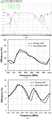
도 6은 아이솔레이션 에이드를 구비하지 않은 내장형 MIMO 안테나의 특성을 나타내는 그래프이다.
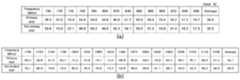
도 7은 아이솔레이션 에이드를 구비하지 않는 안테나의 주파수에 따른 효율 측정 결과 표이다.
도 8은 본 발명의 일 실시예에 따른 LTE 대역을 포함한 다중대역에서 아이솔레이션 에이드를 통해 선택적으로 격리도 특성을 제어할 수 있는 내장형 MIMO 안테나에서 스위치 소자의 제어를 통해 강한 전류 분포 부분만을 아이솔레이션 에이드로 연결한 상태의 안테나 특성을 나타낸 도면이다.
도 9는 아이솔레이션 에이드에 제1, 제2 스위치 소자가 연결되었을 경우 안테나의 주파수에 따른 효율 측정 결과의 표이다.
도 10은 본 발명의 일 실시예에 따른 LTE 대역을 포함한 다중대역에서 아이솔레이션 에이드를 통해 선택적으로 격리도 특성을 제어할 수 있는 내장형 MIMO 안테나에서 스위치 소자의 제어를 통해 그라운드 단락 부분만을 아이솔레이션 에이드로 연결한 상태의 안테나 특성을 나타낸 도면이다.
도 11은 아이솔레이션 에이드에 제3 스위치 소자가 연결되었을 경우 안테나의 주파수에 따른 효율 측정 결과의 표이다.
도 12는 본 발명의 일 실시예에 따른 LTE 대역을 포함한 다중대역에서 아이솔레이션 에이드를 통해 선택적으로 격리도 특성을 제어할 수 있는 내장형 MIMO 안테나에서 스위치 소자의 제어를 통해 강한 전류 분포 부분과 그라운드 단락 부분을 모두 아이솔레이션 에이드로 연결한 상태의 안테나 특성을 나타낸 도면이다.
도 13은 아이솔레이션 에이드에 제1, 제2, 제3 스위치 소자가 모두 연결되었을 경우 안테나의 주파수에 따른 효율 측정 결과의 표이다.
도 14는 아이솔레이션 에이드 유 무에 따른 안테나 간 상관 계수인 ECC(Envelope correlation coefficient) 특성을 나타낸 도면이다.
도 15는 아이솔레이션 에이드가 없을 경우와 아이솔레이션 에이드의 스위치 소자 연결 유무에 따른 안테나의 주파수에 따른 ECC 측정 결과의 표이다.The following drawings attached to this specification are illustrative of preferred embodiments of the present invention, and together with the detailed description of the invention to be described later serve to further understand the technical spirit of the present invention, the present invention is a matter described in such drawings It should not be construed as limited to.
1 is a perspective view showing the configuration of a built-in MIMO antenna that can selectively control the isolation characteristics through the isolation aid in the multi-band including the LTE band according to an embodiment of the present invention.
FIG. 2 is a plan view illustrating an antenna pattern shape of a built-in MIMO antenna capable of selectively controlling isolation characteristics through isolation aids in multiple bands including an LTE band according to an embodiment of the present invention.
3 is a perspective view showing a configuration of a built-in MIMO antenna that can selectively control isolation characteristics through isolation aids in multiple bands including LTE bands according to another embodiment of the present invention.
FIG. 4 is a plan view illustrating the front and rear surfaces of a PCB substrate included in an embedded MIMO antenna capable of selectively controlling isolation characteristics through isolation aids in multiple bands including LTE bands according to another embodiment of the present invention.
FIG. 5 is a plan view illustrating an antenna pattern shape of a built-in MIMO antenna capable of selectively controlling isolation characteristics through isolation aids in multiple bands including LTE bands according to another embodiment of the present invention.
6 is a graph showing the characteristics of the built-in MIMO antenna without the isolation aid.
7 is a table of efficiency measurement results according to a frequency of an antenna without an isolation aid.
FIG. 8 shows only a strong current distribution portion as an isolation aid through control of a switch element in a built-in MIMO antenna capable of selectively controlling isolation characteristics through isolation aids in multiple bands including an LTE band according to an embodiment of the present invention. Figure showing the characteristics of the antenna in the connected state.
9 is a table showing efficiency measurement results according to the frequency of the antenna when the first and second switch elements are connected to the isolation aid.
10 is connected to only the ground short portion through the control of the switch element in the built-in MIMO antenna that can selectively control the isolation characteristics through the isolation aid in the multi-band including the LTE band according to an embodiment of the present invention It is a figure which shows the antenna characteristic of a state.
FIG. 11 is a table illustrating efficiency measurement results according to frequencies of antennas when a third switch element is connected to an isolation aid.
12 is a strong current distribution part and ground short part through control of a switch element in a built-in MIMO antenna capable of selectively controlling isolation characteristics through isolation aids in multiple bands including LTE bands according to an embodiment of the present invention. Figure 2 shows the characteristics of the antenna connected to the isolation aid.
FIG. 13 is a table illustrating efficiency measurement results according to frequencies of antennas when all of the first, second, and third switch elements are connected to the isolation aid.
FIG. 14 is a diagram illustrating ECC (Envelope correlation coefficient) characteristics, which are correlation coefficients between antennas, with and without isolation aid.
15 is a table of ECC measurement results according to the frequency of the antenna when there is no isolation aid and whether the isolation aid is connected or not.
이하, 첨부된 도면을 참조하여 본 발명의 바람직한 실시예를 상세히 설명하기로 한다. 이에 앞서, 본 명세서 및 청구범위에 사용된 용어나 단어는 통상적이거나 사전적인 의미로 한정해서 해석되어서는 아니되며, 발명자는 그 자신의 발명을 가장 최선의 방법으로 설명하기 위해 용어의 개념을 적절하게 정의할 수 있다는 원칙에 입각하여 본 발명의 기술적 사상에 부합하는 의미와 개념으로 해석되어야만 한다. 따라서, 본 명세서에 기재된 실시예와 도면에 도시된 구성은 본 발명의 가장 바람직한 일 실시예에 불과할 뿐이고 본 발명의 기술적 사상을 모두 대변하는 것은 아니므로, 본 출원시점에 있어서 이들을 대체할 수 있는 다양한 균등물과 변형예들이 있을 수 있음을 이해하여야 한다.
Hereinafter, exemplary embodiments of the present invention will be described in detail with reference to the accompanying drawings. Prior to this, terms or words used in the specification and claims should not be construed as having a conventional or dictionary meaning, and the inventors should properly explain the concept of terms in order to best explain their own invention. Based on the principle that can be defined, it should be interpreted as meaning and concept corresponding to the technical idea of the present invention. Therefore, the embodiments described in this specification and the configurations shown in the drawings are merely the most preferred embodiments of the present invention and do not represent all the technical ideas of the present invention. Therefore, It is to be understood that equivalents and modifications are possible.
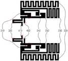
도 1은 본 발명의 일 실시예에 따른 LTE 대역을 포함한 다중대역에서 아이솔레이션 에이드를 통해 선택적으로 격리도 특성을 제어할 수 있는 내장형 MIMO 안테나의 구성을 나타낸 사시도이고, 도 2는 본 발명의 일 실시예에 따른 내장형 MIMO 안테나의 안테나 패턴 형상을 평면으로 나타낸 도면이다.1 is a perspective view showing the configuration of a built-in MIMO antenna that can selectively control isolation characteristics through isolation aids in multiple bands including LTE band according to an embodiment of the present invention, Figure 2 is an embodiment of the present invention Figure is a plan view showing the antenna pattern shape of the built-in MIMO antenna according to the example.
도 1 및 도 2를 참조하여, 본 발명에 따른 내장형 MIMO 안테나의 구성을 설명하기로 한다.1 and 2, a configuration of a built-in MIMO antenna according to the present invention will be described.
도면에 도시된 바와 같이, 본 발명에 따른 내장형 MIMO 안테나(100)는 판 형상의 도전성 물질로 이루어진 그라운드(140)와 상기 그라운드(140) 양쪽 끝단에 각각 위치하는 제1 안테나 소자(110)와 제2 안테나 소자(120) 및 상기 제1 안테나 소자(110)와 상기 제2 안테나 소자(120)에 각각 연결되는 복수의 아이솔레이션 에이드(130)를 포함한다.As shown in the drawing, the built-in
상기 그라운드(140)는 후술할 안테나 소자(110,120)들과 연결되어 접지시키는 역할을 수행한다. 상기 그라운드(140)는 도전성 물질로 이루어지며 사각의 판 형상 구조를 갖는다. 또한, 크기는 소형의 이동통신 단말기 및 휴대용 무선 단말 기기의 면적에 비례하도록 설계되며, 이를 통해 상기 그라운드(140)의 양쪽 끝단에 배치되는 후술할 안테나 소자(110,120)들이 최대의 이격 거리를 확보할 수 있도록 한다. 즉, 소형의 휴대 단말 기기의 면적에 해당하는 크기로 그라운드를 제조한 후, 장측 양단에 각각 안테나 소자(110,120)를 배치하여, 단말 기기 내에 설치할 경우 내장형 다중 안테나의 이격 거리를 최대로 할 수 있다.The
상기 그라운드(140)는 예를 들어 비유전율이 4.4인 FR-4 기판을 이용하여 40 x 60 x 1 mm3 의 크기로 구현할 수 있다.The
상기 제1 안테나 소자(110) 및 상기 제2 안테나 소자(120)는 외부의 신호 회로와 연결되어 전기적 신호를 공급받아 전자기파로 송신하거나 전자기파를 수신하여 상기 신호 회로로 각각 전달하는 MIMO 안테나 역할을 수행한다. 상기 제1 안테나 소자(110) 및 상기 제2 안테나 소자(120)는 상기 그라운드(140)의 장측 양쪽 끝단에 각각 배치되며, 상기 그라운드(140)를 중심으로 서로 대칭되는 형태로 이루어진다. 또한, 상기 제1 안테나 소자(110) 및 상기 제2 안테나 소자(120)는 변형된 IFA(Inverted F Antenna) 형태를 취할 수 있다. 상기 제1 안테나 소자(110) 및 상기 제2 안테나 소자(120)는 소정의 형상으로 이루어진 안테나 패턴(115,125)과 상기 안테나 패턴(115,125)이 고정되는 절연성 물질의 캐리어(116,126)로 이루어지며, 상기 신호 회로와 연결되어 고주파 신호를 입력/출력받는 급전부(400)와 상기 그라운드(140)에 연결되어 접지되는 접지부(410) 등을 포함한다.The
상기 안테나 패턴(115,125)은 다수의 공진체 형태로 이루어지며, 상기 그라운드(140)를 중심으로 서로 대칭되는 형태로 설계된다. 또한, 상기 안테나 패턴(115,125)에 형성된 다수의 공진체는 도 2에서 도시된 바와 같이, 다양한 형태를 취하고 있다. 이와 같이 형성된 다수의 공진체는 다중 공진과 광대역 특성을 유도하기 위하여 삽입된다. 상기 도시된 다수의 공진체는 외곽부터 각각 제1 공진체(220), 제2 공진체(230), 제3 공진체(240), 제4 공진체(250)로 구분할 수 있다.The
상기 안테나 패턴(115,125)에 형성된 공진체 중 상기 제1 공진체(220) 및 상기 제2 공진체(230)는 LTE(700~800MHz), GSM850(824~894MHz), GSM900(880~960MHz) 서비스 대역을 지원하는 역할을 수행한다. 그리고 상기 제3 공진체(240) 및 상기 제4 공진체(250)는 GSM1800(1710~1880MHz), GSM1900(1850~1990MHz), WCDMA(1920~2170MHz) 서비스 대역을 지원하는 역할을 수행한다. 또한, 상기 안테나 패턴(115,125)은 테이퍼 급전 방식으로 이루어질 수 있다.Among the resonators formed in the
상기 캐리어(116,126)는 절연성 수지로 이루어지며 상기 안테나 패턴(115,125)을 기구적으로 지지해주는 역할을 수행한다. 상기 캐리어(116,126)는 표면이 돌출된 직사각형 형태를 이룰 수 있다. 상기 캐리어(116,126)는 예를 들어, 비유전율이 2.9이고, 0.02의 유전체 손실(tanδ)을 갖는 폴리카보네이트(polycarbonate)를 이용하여 40 x 10 x 7 mm3 의 크기로 2.8 cc의 체적을 갖도록 구현할 수 있다. 이 외에도 상기 캐리어(116,126)는 일반적인 이동통신 단말기 및 휴대용 무선 단말 기기에 장착을 고려하여 다양하게 그 크기를 조절하여 구현할 수 있다.The
상기 복수의 아이솔레이션 에이드(130)는 상기 제1 안테나 소자(110) 및 상기 제2 안테나 소자(120)에 각각 연결되어 안테나 소자 간에 격리도 특성을 향상시키는 역할을 수행한다. 상기 복수의 아이솔레이션 에이드(130)는 도전성 물질로 이루어진 케이블이 이용될 수 있으며, 이 외에도 마이크로 스트립 라인(Microstrip Line) 등 다양한 소재가 이용될 수 있다.The isolation aids 130 are connected to the
상기 복수의 아이솔레이션 에이드(130)는 도면에서와 같이 제1 아이솔레이션 에이드(131)와 제2 아이솔레이션 에이드(132)를 포함한다. 상기 제1 아이솔레이션 에이드(131)는 상기 제1 안테나 소자(110)와 상기 제2 안테나 소자(120)에서 표면 전류가 강하게 형성되는 부분(Hot Spot)(310)에 각각 연결된다. 즉, 상기 제1 안테나 소자(110) 및 상기 제2 안테나 소자(120)의 급전부(400) 부근에서 전류 분포가 가장 강하게 형성되는 부분(310)을 상기 제1 아이솔레이션 에이드(131)를 통해 서로 연결하여, 다중 대역 중 저주파수 대역의 격리도 특성을 향상시키도록 한다.The plurality of isolation aids 130 includes a first isolation aid 131 and a
이와 함께, 상기 제2 아이솔레이션 에이드(132)는 상기 제1 안테나 소자(110)와 상기 제2 안테나 소자(120)에서 상기 그라운드(140)와 접지되는 부분의 단락 부분(320)에 각각 연결된다. 즉, 상기 제1 안테나 소자(110) 및 상기 제2 안테나 소자(120)의 접지부(410) 부근에서의 단락 부분(320)을 상기 제2 아이솔레이션 에이드(132)를 통해 서로 연결하여, 다중 대역 중 고주파수 대역의 격리도 특성을 향상시키도록 한다.In addition, the
이와 같이, 상기 제1 아이솔레이션 에이드(131)와 상기 제2 아이솔레이션 에이드(132)를 개별 또는 복수로 구비함으로써 안테나 소자 간의 저주파수 대역과 고주파수 대역 모두에 대한 다중 대역의 격리도 및 반사손실 특성을 향상시킬 수 있다.As such, by providing the first isolation aid 131 and the
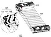
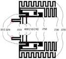
도 3은 본 발명의 다른 실시예에 따른 LTE 대역을 포함한 다중대역에서 아이솔레이션 에이드를 통해 선택적으로 격리도 특성을 제어할 수 있는 내장형 MIMO 안테나의 구성을 나타낸 사시도이고, 도 4는 본 발명의 다른 실시예에 따른 내장형 MIMO 안테나에 포함되는 PCB 기판의 정면(a)과 배면(b)을 나타낸 평면도이고, 도 5는 본 발명의 다른 실시예에 따른 내장형 MIMO 안테나의 안테나 패턴 형상을 평면으로 나타낸 도면이다.3 is a perspective view showing the configuration of a built-in MIMO antenna that can selectively control isolation characteristics through isolation aids in multiple bands including LTE band according to another embodiment of the present invention, Figure 4 is another embodiment of the present invention FIG. 5 is a plan view illustrating a front surface (a) and a rear surface (b) of a PCB substrate included in an embedded MIMO antenna according to an example. FIG. 5 is a plan view illustrating an antenna pattern shape of an embedded MIMO antenna according to another exemplary embodiment of the present invention. .
도 3 내지 도 5를 참조하여, 본 발명의 제2 실시예에 따른 내장형 MIMO 안테나의 구성을 설명하기로 한다.3 to 5, a configuration of a built-in MIMO antenna according to a second embodiment of the present invention will be described.
먼저 상기 도 1과 같은 본 발명의 일 실시예와 같은 경우는 저 주파수 대역의 격리도 특성을 확보하기 위해 사용되는 제1 아이솔레이션 에이드(131), 고 주파수 대역의 격리도 특성을 확보하기 위해 사용되는 제2 아이솔레이션 에이드(132), 그리고 다중 대역에서 동시에 격리도 특성을 확보하기 위해 사용되는 복수의 아이솔레이션 에이드(130)를 별도로 각각 구비하도록 하기에는 협소한 공간에 다수의 아이솔레이션 에이드를 설치하기 어려운 문제가 있다. 또한, 다중 대역 중 각각의 대역에서 안테나 간의 격리도 특성을 제어하도록 활용하기에도 어려운 문제가 있다.First, in the case of the embodiment of the present invention as shown in FIG. 1, the first isolation aid 131 used to secure the isolation characteristic of the low frequency band is used to secure the isolation characteristic of the high frequency band. There is a problem that it is difficult to install a plurality of isolation aids in a narrow space to separately provide the
따라서 본 발명의 제2 실시예에서는 도 3 내지 도 5에서와 같이 내장형 MIMO 안테나에 포함되는 PCB 기판(150)에 안테나 패턴에 연결되는 스트립 라인을 마련하고, 복수의 스위치 소자(137)를 구비하고 이들의 스위칭 동작을 통해 하나의 아이솔레이션 에이드(133)로도 다중 대역에서의 안테나 간 격리도 특성을 제어할 수 있도록 한다.Accordingly, in the second embodiment of the present invention, as shown in FIGS. 3 to 5, a strip line connected to the antenna pattern is provided on the
우선, 스트립 라인(210)을 마련하여 안테나 패턴에서 표면 전류가 강하게 형성되는 부분(310)과 PCB 기판(150)을 연결하도록 한다. 다음, 기판(150) 상에 상기 표면 전류가 강하게 형성되는 부분(310)에 연결된 스트립 라인(210)과 안테나 패턴과 그라운드(140)가 접지되는 부분의 단락 부분(410)에 각각 스위치 소자(134,135,136)를 설치한다. 그리고 상기 각 부분(210,410)을 스트립 라인(138)으로 연결한다. 이렇게 제1 안테나 소자(110)와 제2 안테나 소자(120) 각각에서 상기 각 지점(210,410)이 연결된 부분을 하나의 아이솔레이션 에이드(133)를 통해 연결한다. 또한, 상기 안테나 패턴의 각 부분(210,410)은 PCB 기판(150)에 형성된 비아 홀(Via Hole)(139,139')을 통해 상기 PCB 기판(150) 배면에 형성된 상기 스트립 라인(138)에 연결되고, 이를 통해 상기 안테나 패턴의 각 지점(210,410)을 서로 연결하게 된다.First, the
아울러, 상기 복수의 스위치 소자(134,135,136)의 온/오프 동작을 제어하는 스위칭 제어부(미도시)를 구비하여, 상기 표면 전류 분포가 강하게 형성되는 부분(310)과 상기 그라운드에 접지되는 단락 부분(320) 모두를 상기 아이솔레이션 에이드(133)에 접속 시키거나, 상기 두 부분(310,320) 중 어느 한 부분만을 상기 아이솔레이션 에이드(130)에 접속시키거나, 상기 두 부분(310,320) 모두를 상기 아이솔레이션 에이드(130)에 접속 차단시키는 등의 선택적인 제어 처리를 수행하도록 한다.In addition, a switching controller (not shown) for controlling on / off operations of the plurality of
이때, 상기 스위치 소자(137)는 다이오드, 트랜지스터, FET, MEMS 스위치 소자 등 전류와 전압을 이용하여 스위칭 역할이 가능한 RF 스위치 소자를 이용할 수 있다. 이 외에도 회로의 온/오프 동작을 수행할 수 있는 다양한 스위치 소자가 이용될 수 있다.In this case, the
이와 같이, 스위치 소자(137)와 아이솔레이션 에이드(133)를 통해서 상기 안테나 패턴의 각 부분(310,320)을 연결함으로써, 스위치 소자의 스위칭 제어에 따라 다중 대역 중 각각의 대역의 안테나 소자 간 격리도 특성을 제어할 수 있게 된다.As such, by connecting the
아울러, 상기 아이솔레이션 에이드(133)는 상기 두 부분(310,320) 중 상기 그라운드(140)에 접지되는 단락 부분(320)과 가까운 부분에 연결되도록 하여, 제1 안테나 소자(110)와 제2 안테나 소자(120)를 연결하는 상기 아이솔레이션 에이드(133)의 각 부분을 연결하는 총 길이가 서로 다르도록 한다. 즉, 두 부분 중 단락 부분(320)이 연결되는 길이가 단축이 되도록 하고, 강한 전류 부분(310)이 장축이 되도록 한다. 이는 저주파 대역의 격리도 특성을 향상하기 위해서는 고주파 대역의 아이솔레이션 에이드(133) 길이 보다 길게 형성되는 것이 바람직하기 때문이다.In addition, the
이하에서는 아이솔레이션 에이드 유/무와 스위치 소자에 의해 표면 전류 분포가 강한 부분(310)과 단락 부분(320)을 각각 연결하거나 둘 다 연결한 상태에서의 MIMO 안테나의 반사손실과 격리도 특성, 그리고 효율 특성, ECC 특성을 도면을 통해 비교하도록 한다.Hereinafter, the reflection loss, isolation characteristics, and efficiency characteristics of the MIMO antenna with or without an isolation aid and a switch element having the strong surface current distribution and the shorting
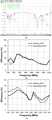
도 6은 아이솔레이션 에이드를 구비하지 않은 내장형 MIMO 안테나의 특성을 나타내는 그래프이다.6 is a graph showing the characteristics of the built-in MIMO antenna without the isolation aid.
도 6 (a)는 반사손실과 격리도 특성을 나타내고, (b)는 저 주파수 대역의 효율 특성을 나타내고, (c)는 고 주파수 대역의 효율 특성을 나타낸다.6 (a) shows the reflection loss and isolation characteristics, (b) shows the efficiency characteristics of the low frequency band, and (c) shows the efficiency characteristics of the high frequency band.
도 6 (a)를 참조하면, 아이솔레이션 에이드를 구비하지 않은 내장형 MIMO 안테나의 대역폭은 임피던스 정합 정도를 나타내는 전압정재파비(이하, VSWR이라 한다) VSWR > 3을 기준으로 저 주파수 대역에서는 상단에 위치한 제1 안테나 소자의 경우 686 ~ 887 MHz의 대역폭과 하단에 위치한 제2 안테나 소자의 경우 685 ~ 822 MHz의 대역폭을 갖는다. 또한, 고 주파수 대역에서 제1 안테나 소자는 1710 ~ 2045 MHz의 대역폭을 가지고, 제2 안테나 소자는 1686 ~ 2045 MHz의 대역폭을 갖는다. 하지만, 아이솔레이션 에이드를 구비하지 않을 경우 이동통신 단말기와 같이 소형의 단말기에서는 충분한 접지면이 갇혀 있지 않으므로 안테나 간의 상호 전자기적 간섭으로 인하여 동작 대역폭 안에서 저 주파수 대역에서는 -5.4 dB 이하, 고 주파수 대역에서는 -9.1 dB 이하의 매우 낮은 격리도 특성을 나타냄을 알 수 있다.Referring to FIG. 6 (a), the bandwidth of the built-in MIMO antenna without the isolation aid is determined by the voltage standing wave ratio (hereinafter referred to as VSWR) representing the impedance matching degree. The first antenna element has a bandwidth of 686 to 887 MHz and the second antenna element located at the bottom has a bandwidth of 685 to 822 MHz. In addition, in the high frequency band, the first antenna element has a bandwidth of 1710 to 2045 MHz, and the second antenna element has a bandwidth of 1686 to 2045 MHz. However, if the isolation aid is not provided, a sufficient ground plane is not trapped in a small terminal such as a mobile communication terminal, and thus, due to mutual electromagnetic interference between antennas, -5.4 dB or less in the low frequency band and-in the high frequency band due to mutual electromagnetic interference between antennas. It can be seen that it exhibits very low isolation characteristics of less than 9.1 dB.
안테나의 효율은 전파 무반사실에서 측정하였으며, 저 주파수 대역은 700 MHz에서 960 MHz까지 20 MHz 단위로 고 주파수 대역은 1700 MHz부터 2180 MHz까지 30 MHz 단위로 전 대역을 측정하였다.The efficiency of the antenna was measured in the radio wave anechoic chamber, and the low frequency band was measured in 20 MHz units from 700 MHz to 960 MHz and the entire band was measured in 30 MHz units from 1700 MHz to 2180 MHz.
도 6 (b), (c)를 참조하면, 안테나의 효율은 동작 주파수 대역인 저 주파수 대역 700-960 MHz에서 제1 안테나 소자는 최대 53.2%, 최소 18.6%로써 평균 34.2%의 효율을, 제2 안테나 소자는 최대 51.4%, 최소 18.7%으로써 평균 32.7%의 효율을 갖는다. 또한 고 주파수 대역인 1700-2180 MHz에서는 제1 안테나 소자의 경우 최대 66.4%, 최소 33.7%로써 평균 49.6%의 효율을, 제2 안테나 소자의 경우 최대 75.8%, 최소 25.9%으로써 평균 50.6%의 효율을 갖는다.6 (b) and 6 (c), in the low frequency band 700-960 MHz, which is an operating frequency band, the first antenna element has a maximum efficiency of 53.2% and a minimum of 18.6%. The two antenna elements have an average efficiency of 32.7% with a maximum of 51.4% and a minimum of 18.7%. In addition, in the high frequency band 1700-2180 MHz, the average efficiency of 49.6% is maximized with a maximum of 66.4% and at least 33.7% for a first antenna element, and an average of 50.6% with a maximum of 75.8% and a minimum of 25.9% for a second antenna element. Has
아이솔레이션 에이드를 구비하지 않는 안테나의 주파수에 따른 효율 측정 결과 표를 도 7에 도시하였다.Table 7 shows the result of measuring the efficiency according to the frequency of the antenna without the isolation aid.
도 8은 본 발명의 일 실시예에 따른 LTE 대역을 포함한 다중대역에서 아이솔레이션 에이드를 통해 선택적으로 격리도 특성을 제어할 수 있는 내장형 MIMO 안테나에서 스위치 소자의 제어를 통해 강한 전류 분포 부분만을 아이솔레이션 에이드로 연결한 상태의 안테나 특성을 나타낸 도면이다.FIG. 8 shows only a strong current distribution portion as an isolation aid through control of a switch element in a built-in MIMO antenna capable of selectively controlling isolation characteristics through isolation aids in multiple bands including an LTE band according to an embodiment of the present invention. Figure showing the characteristics of the antenna in the connected state.
도 8 (a)는 반사손실과 격리도 특성을 나타내고, (b)는 저 주파수 대역의 효율 특성을 나타내고, (c)는 고 주파수 대역의 효율 특성을 나타낸다.8 (a) shows the reflection loss and the isolation characteristics, (b) shows the efficiency characteristics of the low frequency band, and (c) shows the efficiency characteristics of the high frequency band.
도 8 (a)의 반사손실 및 격리도 특성을 살펴보면, VSWR > 3을 기준으로 저 주파수 대역에서는 제1 안테나 소자의 경우 693 ~ 888 MHz의 대역폭과 제2 안테나 소자의 경우 689 ~ 870 MHz, 915 ~ 942 MHz의 대역폭으로 아이솔레이션 에이드를 구비하지 않을 때보다 대역폭은 감소하였지만, 안테나 소자 간의 격리도는 -5.4 dB 이하에서 -13.2 dB 이하로 크게 향상되었다. 하지만 고 주파수 대역의 공진 주파수는 저 주파수 대역 방향으로 크게 이동하였음을 알 수 있다.Referring to the return loss and isolation characteristics of FIG. 8 (a), the bandwidth of 693 to 888 MHz for the first antenna element and 689 to 870 MHz, 915 for the second antenna element in the low frequency band based on VSWR> 3 Although the bandwidth is reduced to a bandwidth of ~ 942 MHz than without an isolation aid, the isolation between the antenna elements is greatly improved from -5.4 dB to -13.2 dB. However, it can be seen that the resonant frequency of the high frequency band has moved greatly in the low frequency band direction.
도 8의 (b) 및 (c)를 참조하면, 안테나의 효율은 동작 주파수 대역인 저 주파수 대역 700-960 MHz에서 제1 안테나 소자는 최대 67.0%, 최소 26.5%로써 평균 43.3%의 효율을, 제2 안테나 소자는 최대 67.9%, 최소 26.0%으로써 평균 44.2%의 효율을 갖는다. 또한 고 주파수 대역에서는 공진 주파수가 저 주파수 대역 방향으로 이동함에 따라 효율 특성이 크게 감소하였다. 따라서, 아이솔레이션 에이드에 제1(134), 제2(135) 스위치 소자만 연결되어 저 주파수 대역에서 우수한 격리도 특성과 함께 효율도 크게 증가함을 알 수 있다.Referring to (b) and (c) of FIG. 8, in the low frequency band 700-960 MHz, which is an operating frequency band, the first antenna element has a maximum efficiency of 63.3% and a minimum of 26.5%, with an average efficiency of 43.3%. The second antenna element has an efficiency of 44.2% on average with a maximum of 67.9% and a minimum of 26.0%. In addition, in the high frequency band, the efficiency characteristic is greatly reduced as the resonant frequency moves toward the low frequency band. Accordingly, it can be seen that only the first 134 and the second 135 switch elements are connected to the isolation aid, so that the efficiency is greatly increased with excellent isolation characteristics in the low frequency band.
아이솔레이션 에이드에 제1(134), 제2(135) 스위치 소자가 연결되었을 경우 안테나의 주파수에 따른 효율 측정 결과의 표를 도 9에 도시하였다.9 is a table illustrating efficiency measurement results according to the frequency of the antenna when the first 134 and the second 135 switch elements are connected to the isolation aid.
도 10은 본 발명의 일 실시예에 따른 LTE 대역을 포함한 다중대역에서 아이솔레이션 에이드를 통해 선택적으로 격리도 특성을 제어할 수 있는 내장형 MIMO 안테나에서 스위치 소자의 제어를 통해 그라운드 단락 부분만을 아이솔레이션 에이드로 연결한 상태의 안테나 특성을 나타낸 도면이다.10 is connected to only the ground short portion through the control of the switch element in the built-in MIMO antenna that can selectively control the isolation characteristics through the isolation aid in the multi-band including the LTE band according to an embodiment of the present invention It is a figure which shows the antenna characteristic of a state.
도 10 (a)는 반사손실과 격리도 특성을 나타내고, (b)는 저 주파수 대역의 효율 특성을 나타내고, (c)는 고 주파수 대역의 효율 특성을 나타낸다.10 (a) shows return loss and isolation characteristics, (b) shows efficiency characteristics of the low frequency band, and (c) shows efficiency characteristics of the high frequency band.
도 10 (a)의 반사손실 및 격리도 특성을 살펴보면, VSWR > 3을 기준으로 저 주파수 대역에서는 제1 안테나 소자의 경우 751 ~ 810 MHz의 대역폭과 제2 안테나 소자의 경우 751 ~ 823 MHz의 대역폭을 가졌고, 동작 대역폭 안에서 -10.0 dB 이하의 격리도 특성을 가졌다. 고 주파수 대역에서는 제1 안테나 소자의 경우 1651 ~ 2051 MHz의 대역폭과 제2 안테나 소자의 경우 1617 ~ 2045 MHz의 대역폭을 가짐으로 아이솔레이션 에이드를 구비하지 않을 경우보다 약간 대역폭이 확장되었으며, 제1 안테나와 제2 안테나 소자 간의 격리도는 -12.1 dB 이하로 아이솔레이션 에이드가 없을 경우보다 약 3 dB 이상 향상되었다.Referring to the return loss and isolation characteristics of FIG. 10 (a), the bandwidth of 751 to 810 MHz for the first antenna element and the bandwidth of 751 to 823 MHz for the second antenna element in the low frequency band based on VSWR> 3 It has an isolation characteristic of -10.0 dB below the operating bandwidth. In the high frequency band, the bandwidth of 1651 to 2051 MHz for the first antenna element and the bandwidth of 1617 to 2045 MHz for the second antenna element are slightly increased than those without the isolation aid. The isolation between the second antenna elements is -12.1 dB or less, about 3 dB more than without an isolation aid.
도 10의 (b) 및 (c)를 참조하면, 안테나의 효율은 동작 주파수 대역인 저 주파수 대역 700-960 MHz에서 아이솔레이션 에이드가 없을 경우와 거의 유사한 특성을 가졌다. 그리고 고 주파수 대역 1700-2180 MHz에서는 제1 안테나 소자는 최대 75.3%, 최소 39.2%로써 평균 59.1%의 효율을, 제2 안테나 소자는 최대 83.0%, 최소 36.6%으로써 평균 60.9%의 효율을 갖는다. 따라서, 아이솔레이션 에이드에 제3 스위치 소자만(136) 연결되어 고 주파수 대역에서 우수한 격리도 특성과 함께 효율도 크게 증가함을 알 수 있다.Referring to (b) and (c) of FIG. 10, the efficiency of the antenna has almost the same characteristics as in the absence of isolation aid in the low frequency band 700-960 MHz, which is an operating frequency band. In the high frequency band 1700-2180 MHz, the first antenna element has an efficiency of 59.1% with a maximum of 75.3% and a minimum of 39.2%, and the second antenna element has an efficiency of 60.9% with a maximum of 83.0% and a minimum of 36.6%. Accordingly, it can be seen that only the
아이솔레이션 에이드에 제3 스위치 소자(136)가 연결되었을 경우 안테나의 주파수에 따른 효율 측정 결과의 표를 도 11에 도시하였다.11 shows a table of efficiency measurement results according to the frequency of the antenna when the
도 12는 본 발명의 일 실시예에 따른 LTE 대역을 포함한 다중대역에서 아이솔레이션 에이드를 통해 선택적으로 격리도 특성을 제어할 수 있는 내장형 MIMO 안테나에서 스위치 소자의 제어를 통해 강한 전류 분포 부분과 그라운드 단락 부분을 모두 아이솔레이션 에이드로 연결한 상태의 안테나 특성을 나타낸 도면이다.12 is a strong current distribution part and ground short part through control of a switch element in a built-in MIMO antenna capable of selectively controlling isolation characteristics through isolation aids in multiple bands including LTE bands according to an embodiment of the present invention. Figure 2 shows the characteristics of the antenna connected to the isolation aid.
도 12 (a)는 반사손실과 격리도 특성을 나타내고, (b)는 저 주파수 대역의 효율 특성을 나타내고, (c)는 고 주파수 대역의 효율 특성을 나타낸다.12 (a) shows return loss and isolation characteristics, (b) shows the efficiency characteristics of the low frequency band, and (c) shows the efficiency characteristics of the high frequency band.
도 12 (a)의 반사손실 및 격리도 특성을 살펴보면, VSWR > 3을 기준으로 저 주파수 대역에서는 제1 안테나 소자의 경우 758 ~ 878 MHz의 대역폭과 제2 안테나 소자의 경우 761 ~ 878 MHz의 대역폭을 가졌고, 동작 대역폭 안에서 -11.6 dB 이하의 격리도 특성을 가졌다. 고 주파수 대역에서는 제1 안테나 소자의 경우 1710 ~ 2052 MHz의 대역폭과 제2 안테나 소자의 경우 1707 ~ 2072 MHz의 대역폭을 가졌고, 동작 대역폭 안에서 -11.3 dB 이하의 안테나 소자 간 격리도 특성을 가졌다.Referring to the reflection loss and isolation characteristics of FIG. 12 (a), the bandwidth of 758 to 878 MHz for the first antenna element and 761 to 878 MHz for the second antenna element in the low frequency band based on VSWR> 3 And isolation characteristics of less than -11.6 dB within the operating bandwidth. In the high frequency band, the first antenna element has a bandwidth of 1710 to 2052 MHz and the second antenna element has a bandwidth of 1707 to 2072 MHz, and has an isolation characteristic between antenna elements of -11.3 dB or less within the operating bandwidth.
도 12의 (b) 및 (c)를 참조하면, 안테나의 효율은 저 주파수 대역 700-960 MHz에서 제1 안테나 소자는 최대 68.2%, 최소 19.6%로써 평균 40.1%의 효율과, 제2 안테나 소자는 최대 63.2%, 최소 21.8% 로서 평균 39.5%의 효율을 가졌다. 또한 고 주파수 대역 1700-2180 MHz에서는 제1 안테나 소자는 최대 82.6%, 최소 33.3%로써 평균 58.2%의 효율을, 제2 안테나 소자는 최대 84.6%, 최소 24.7%으로써 평균 54.8%의 효율을 갖는다. 제1, 제2, 제3 스위치 소자(137) 모두 연결할 경우 각각의 대역만 격리도 특성을 향상시켰을 경우보다 성능이 약간 저하되지만 아이솔레이션 에이드가 없을 경우보다는 크게 격리도 및 효율 특성이 향상됨을 알 수 있다.Referring to FIGS. 12B and 12C, the efficiency of the antenna is 68.2% for the first antenna element and 19.6% for the first antenna element in the low frequency band 700-960 MHz, and an average of 40.1% and the second antenna element. Had an average efficiency of 39.5% with a maximum of 63.2% and a minimum of 21.8%. In addition, in the high frequency band 1700-2180 MHz, the first antenna element has an efficiency of 58.2% on average with a maximum of 82.6% and a minimum of 33.3%. The second antenna element has an efficiency of 54.8% with an average of 84.6% and a minimum of 24.7%. When the first, second, and
아이솔레이션 에이드에 제1, 제2, 제3 스위치 소자(137)가 모두 연결되었을 경우 안테나의 주파수에 따른 효율 측정 결과의 표를 도 13에 도시하였다.FIG. 13 shows a table of efficiency measurement results according to the frequency of the antenna when the first, second, and
이상에서와 같이 측정된 결과 및 그래프에 따르면, 본 발명의 실시예에 따른 내장형 MIMO 안테나는 아이솔레이션 에이드를 구비함으로써, 아이솔레이션 에이드에 각각의 스위치 소자를 개별 연결 및 모두 연결하였을 경우 LTE 대역을 포함한 다중대역에서 주파수에 무관한 안테나 소자 간의 격리 특성을 확보할 수 있다.According to the measured results and graphs as described above, the built-in MIMO antenna according to the embodiment of the present invention has an isolation aid, and when each switch element is individually connected and all connected to the isolation aid, the multiband including the LTE band. It is possible to secure isolation characteristics between antenna elements regardless of frequency.
도 14는 아이솔레이션 에이드 유/무에 따른 안테나 간 상관 계수인 ECC(Envelope correlation coefficient) 특성을 나타낸 도면이다.FIG. 14 is a diagram illustrating ECC (Envelope correlation coefficient) characteristics, which are correlation coefficients between antennas, with and without isolation aid.
도 14 (a)는 저 주파수 대역(700-960 MHz)의 ECC 특성을 나타내고, 도 14 (b)는 고 주파수 대역(1700-2180 MHz)의 ECC 특성을 나타낸다.14 (a) shows the ECC characteristics of the low frequency band (700-960 MHz), and FIG. 14 (b) shows the ECC characteristics of the high frequency band (1700-2180 MHz).
도 14 (a)를 살펴보면, 아이솔레이션 에이드가 구비되지 않은 경우(Default) 중심주파수에서 0.16의 최소값을 가지고, 중심주파수를 기준으로 낮은 쪽 주파수와 높은 쪽 주파수는 점차 증가하여 최대 0.56의 ECC를 갖는다. 그러나, 아이솔레이션 에이드를 제1(134), 제2(135) 스위치 소자만 연결하여 저 주파수 대역의 격리 특성을 향상시킨 결과(LIA: Low isolation aid) 중심주파수에서 0.15의 최소값을 가지고, 중심주파수를 기준으로 낮은 쪽 주파수와 높은 쪽 주파수는 점차 증가하지만 최대 0.30의 ECC를 가짐으로 아이솔레이션 에이드가 없을 경우보다 ECC 특성이 크게 향상됨을 알 수 있다. 또한, 아이솔레이션 에이드에 스위치 소자를 모두 연결한(137) 경우(DIA: Double isolation aid) 700-920 MHz 구간에서는 아이솔레이션 에이드가 없을 경우보다 ECC가 평균 0.04 향상되며, 940-960 MHz에서는 ECC가 평균 0.09 저하되는 것을 알 수 있다.Referring to FIG. 14A, when the isolation aid is not provided (Default), the center frequency has a minimum value of 0.16, and the lower and higher frequencies gradually increase with respect to the center frequency to have an maximum ECC of 0.56. However, the isolation aid is connected to only the first 134 and the second 135 switches to improve the isolation characteristics of the low frequency band (LIA: Low isolation aid), and has a minimum value of 0.15 at the center frequency. As a reference, the lower and higher frequencies gradually increase, but the ECC has a maximum EC of 0.30. Thus, the ECC characteristics are significantly improved compared to the absence of isolation aid. In addition, when all the switch elements are connected to the isolation aid (137) (DIA: Double isolation aid), the ECC is improved by 0.04 on average in the 700-920 MHz section, and the average ECC is 0.09 on the 940-960 MHz. It can be seen that the degradation.
도 14 (b)를 살펴보면, 아이솔레이션 에이드가 없을 경우(Default) 최대 0.67, 최소 0.22로 평균 0.42의 ECC를 갖는다. 그러나, 아이솔레이션 에이드를 구비하고 제3 스위치 소자(134)만 연결하여 고 주파수 대역의 안테나간 격리 특성을 확보할 경우(HIA: High isolation aid) 최대 0.43, 최소 0.20로 평균 0.31의 ECC 값을 가지므로 아이솔레이션 에이드가 없을 경우보다 크게 향상됨을 확인할 수 있다. 또한, 아이솔레이션 에이드에 스위치 소자를 모두 연결한(137) 경우(DIA) 최대 0.65, 최소 0.30로 평균 0.48의 ECC 값을 가지므로 아이솔레이션 에이드가 없을 경우보다 ECC가 평균 0.06 저하되는 것을 알 수 있다.Referring to FIG. 14 (b), when there is no isolation aid (Default), the ECC has an average of 0.42 with a maximum of 0.67 and a minimum of 0.22. However, when the isolation aid is provided and only the
아이솔레이션 에이드가 없을 경우와 아이솔레이션 에이드의 스위치 소자 연결 유/무에 따른 안테나의 주파수에 따른 ECC 측정 결과의 표를 도 15에 도시하였다.15 shows a table of ECC measurement results according to the frequency of the antenna when there is no isolation aid and whether or not the isolation element is connected with or without a switch element.
이상 위의 측정 결과 등에 따르면, 본 발명의 실시예에 따른 내장형 MIMO 안테나는 아이솔레이션 에이드를 구비함으로써, 각각의 스위치 소자를 통해 개별 연결 및 모두 연결하였을 경우 LTE 대역을 포함한 다중대역에서 주파수에 무관한 안테나 간의 격리도 특성 확보와 더불어 효율 증가 및 안테나간의 상관 계수를 확보할 수 있다.According to the above measurement results, the built-in MIMO antenna according to an embodiment of the present invention is provided with an isolation aid, when the individual connection and all connected through each switch element, the antenna regardless of the frequency in the multi-band including the LTE band In addition to securing the isolation characteristics between the antennas, efficiency and correlation coefficient between antennas can be secured.
이상에서 본 발명은 비록 한정된 실시예와 도면에 의해 설명되었으나, 본 발명은 이것에 의해 한정되지 않으며 본 발명이 속하는 기술분야에서 통상의 지식을 가진 자에 의해 본 발명의 기술사상과 아래에 기재될 특허청구범위의 균등범위 내에서 다양한 수정 및 변형이 가능함은 물론이다.Although the present invention has been described above by means of limited embodiments and drawings, the present invention is not limited thereto and will be described below by the person skilled in the art to which the present invention pertains. Of course, various modifications and variations are possible within the scope of the claims.
<도면의 주요 부분에 대한 부호의 설명>
100 : 내장형 MIMO 안테나 110 : 제1 안테나 소자
120 : 제2 안테나 소자 130 : 복수의 아이솔레이션 에이드
140 : 그라운드 400 : 급전부
410 : 접지부<Explanation of symbols for the main parts of the drawings>
100: built-in MIMO antenna 110: first antenna element
120: second antenna element 130: a plurality of isolation aids
140: ground 400: feeder
410: ground portion
Claims (13)
Translated fromKorean상기 그라운드의 일단에 위치한 제1 안테나 소자;
상기 그라운드의 타단에 위치한 제2 안테나 소자;
상기 제1 안테나 소자와 상기 제2 안테나 소자 모두에서 표면 전류가 강하게 형성되는 부분(Hot Spot)에 각각 연결된 제1 아이솔레이션 에이드; 및
상기 제1 안테나 소자와 상기 제2 안테나 소자 모두에서 상기 그라운드와 접지되는 단락 부분에 각각 연결된 제2 아이솔레이션 에이드;를 포함하는 LTE 대역을 포함한 다중대역에서 아이솔레이션 에이드를 통해 선택적으로 격리도 특성을 제어할 수 있는 내장형 MIMO 안테나.Plate-shaped ground for grounding the antenna;
A first antenna element located at one end of the ground;
A second antenna element located at the other end of the ground;
First isolation aids connected to hot spots in which surface currents are strongly formed in both the first antenna element and the second antenna element; And
A second isolation aid connected to each of the first antenna element and the second antenna element respectively connected to the grounded and short-circuited portion; and controlling isolation characteristics through isolation aid in multiple bands including an LTE band. Built-in MIMO antenna.
상기 제1 아이솔레이션 에이드는,
상기 제1 안테나 소자 및 상기 제2 안테나 소자 사이에서 저 주파수 대역의 격리도 특성을 향상시키고,
상기 제2 아이솔레이션 에이드는,
상기 제1 안테나 소자 및 상기 제2 안테나 소자 사이에서 고 주파수 대역의 격리도 특성을 향상시키는 것을 특징으로 하는 LTE 대역을 포함한 다중대역에서 아이솔레이션 에이드를 통해 선택적으로 격리도 특성을 제어할 수 있는 내장형 MIMO 안테나.The method of claim 1,
The first isolation aid,
Improve the isolation characteristics of the low frequency band between the first antenna element and the second antenna element,
The second isolation aid,
Built-in MIMO capable of selectively controlling isolation characteristics through isolation aids in multiple bands including LTE bands, which improves isolation characteristics of a high frequency band between the first antenna element and the second antenna element. antenna.
상기 제1 안테나 소자 및 상기 제2 안테나 소자는,
상기 그라운드를 중심으로 대칭되는 형태로 이루어진 것을 특징으로 하는 LTE 대역을 포함한 다중대역에서 아이솔레이션 에이드를 통해 선택적으로 격리도 특성을 제어할 수 있는 내장형 MIMO 안테나.The method of claim 1,
The first antenna element and the second antenna element,
Built-in MIMO antenna that can selectively control the isolation characteristics through the isolation aid in the multi-band including the LTE band, characterized in that formed in a symmetrical form around the ground.
상기 제1 안테나 소자 및 상기 제2 안테나 소자는,
다수의 공진체 형태로 이루어진 안테나 패턴과,
상기 안테나 패턴이 고정되는 캐리어로 이루어진 것을 특징으로 하는 LTE 대역을 포함한 다중대역에서 아이솔레이션 에이드를 통해 선택적으로 격리도 특성을 제어할 수 있는 내장형 MIMO 안테나.The method of claim 1,
The first antenna element and the second antenna element,
An antenna pattern having a plurality of resonator shapes,
And a built-in MIMO antenna capable of selectively controlling isolation characteristics through isolation aids in multiple bands including LTE bands, characterized in that the antenna pattern is fixed carrier.
상기 안테나 패턴은,
LTE, GSM850, GSM900 서비스 대역을 지원하기 위한 제1 공진체, 제2 공진체와,
GSM1800, GSM1900, WCDMA 서비스 대역을 지원하기 위한 제3 공진체, 제4 공진체를 포함하며,
테이퍼 급전 방식으로 이루어진 것을 특징으로 하는 LTE 대역을 포함한 다중대역에서 아이솔레이션 에이드를 통해 선택적으로 격리도 특성을 제어할 수 있는 내장형 MIMO 안테나.The method of claim 5, wherein
The antenna pattern is,
A first resonator and a second resonator for supporting LTE, GSM850, and GSM900 service bands;
A third resonator and a fourth resonator for supporting GSM1800, GSM1900, and WCDMA service bands;
Built-in MIMO antenna that can selectively control the isolation characteristics through the isolation aid in the multi-band including the LTE band characterized in that the tapered feeding method.
상기 제1 안테나 소자 및 상기 제2 안테나 소자는,
변형된 IFA(Inverted F Antenna) 형태의 안테나인 것을 특징으로 하는 LTE 대역을 포함한 다중대역에서 아이솔레이션 에이드를 통해 선택적으로 격리도 특성을 제어할 수 있는 내장형 MIMO 안테나.The method of claim 1,
The first antenna element and the second antenna element,
Built-in MIMO antenna that can selectively control the isolation characteristics through the isolation aid in the multi-band including the LTE band, characterized in that the modified Inverted F Antenna (IFA) type antenna.
상기 제1 안테나 소자 및 상기 제2 안테나 소자는,
신호 회로와 연결되어 각각을 급전시키는 급전부를 더 포함하는 것을 특징으로 하는 LTE 대역을 포함한 다중대역에서 아이솔레이션 에이드를 통해 선택적으로 격리도 특성을 제어할 수 있는 내장형 MIMO 안테나.The method of claim 1,
The first antenna element and the second antenna element,
A built-in MIMO antenna capable of selectively controlling isolation characteristics through isolation aids in multiple bands including LTE bands, further comprising a feeder connected to the signal circuit to feed each of the plurality of feeders.
상기 제1 안테나 소자 및 상기 제2 안테나 소자는,
상기 그라운드에 연결되어 접지시키는 접지부를 더 포함하는 것을 특징으로 하는 LTE 대역을 포함한 다중대역에서 아이솔레이션 에이드를 통해 선택적으로 격리도 특성을 제어할 수 있는 내장형 MIMO 안테나.The method of claim 1,
The first antenna element and the second antenna element,
Built-in MIMO antenna that can selectively control the isolation characteristics through the isolation aid in the multi-band including the LTE band, characterized in that it further comprises a ground connected to the ground to ground.
상기 그라운드의 일단에 위치한 제1 안테나 소자;
상기 그라운드의 타단에 위치한 제2 안테나 소자; 및
상기 제1 안테나 소자와 상기 제2 안테나 소자를 연결하며, 상기 제1 안테나 소자와 상기 제2 안테나 소자 모두에서 전류 분포가 강하게 형성되는 부분(Hot Spot)과 상기 그라운드에 접지되는 단락 부분에 모두 접속되는 아이솔레이션 에이드;를 포함하는 것을 특징으로 하는 LTE 대역을 포함한 다중대역에서 아이솔레이션 에이드를 통해 선택적으로 격리도 특성을 제어할 수 있는 내장형 MIMO 안테나.Plate-shaped ground for grounding the antenna;
A first antenna element located at one end of the ground;
A second antenna element located at the other end of the ground; And
The first antenna element and the second antenna element are connected to each other and are connected to both a hot spot and a short circuit part grounded to the ground in both the first antenna element and the second antenna element. Built-in MIMO antenna that can selectively control the isolation characteristics through the isolation aid in the multi-band including the LTE band, characterized in that it comprises a.
상기 아이솔레이션 에이드와 상기 각 안테나 소자가 연결되는 부분에 구비되며, 상기 각 안테나 소자에서 상기 전류 분포가 강하게 형성되는 부분과 상기 그라운드에 접지되는 단락 부분의 접속을 스위칭하는 스위치 소자;를 더 포함하는 것을 특징으로 하는 LTE 대역을 포함한 다중대역에서 아이솔레이션 에이드를 통해 선택적으로 격리도 특성을 제어할 수 있는 내장형 MIMO 안테나.The method of claim 10,
A switch element provided at a portion at which the isolation aid and each antenna element are connected, and switching a connection between a portion in which the current distribution is strongly formed in each antenna element and a shorting portion grounded to the ground; Built-in MIMO antenna to selectively control isolation characteristics through isolation aids in multiple bands, including the LTE band.
상기 스위치 소자를 제어하여, 상기 전류 분포가 강하게 형성되는 부분과 상기 그라운드에 접지되는 단락 부분 모두를 접속시키거나, 상기 두 부분 중 어느 한 부분만을 접속시키거나, 상기 두 부분 모두의 접속을 차단시키도록 제어하는 스위칭 제어부;를 더 포함하는 것을 특징으로 하는 LTE 대역을 포함한 다중대역에서 아이솔레이션 에이드를 통해 선택적으로 격리도 특성을 제어할 수 있는 내장형 MIMO 안테나.The method of claim 11,
The switch element is controlled to connect both the portion in which the current distribution is strongly formed and the short circuit portion grounded to the ground, to connect only one of the two portions, or to block the connection of both portions. And a switching controller for controlling the system to further control the isolation characteristic through the isolation aid in the multi-band including the LTE band.
상기 스위치 소자는,
다이오드, 트랜지스터, FET(Field Effect Transistor), MEMS(Micro Electro Mechanical Systems) 스위치 소자와 같은 전류와 전압을 이용하여 스위칭 역할이 가능한 RF 스위치 소자를 포함하는 것을 특징으로 하는 LTE 대역을 포함한 다중대역에서 아이솔레이션 에이드를 통해 선택적으로 격리도 특성을 제어할 수 있는 내장형 MIMO 안테나.The method of claim 11,
The switch element,
Isolation in multiple bands including LTE bands, including RF switch elements capable of switching using current and voltage, such as diodes, transistors, field effect transistors (FETs) and micro electro mechanical systems (MEMS) switch elements Built-in MIMO antenna with selective control of isolation characteristics via aid.
Priority Applications (2)
| Application Number | Priority Date | Filing Date | Title |
|---|---|---|---|
| KR1020100016177AKR100986702B1 (en) | 2010-02-23 | 2010-02-23 | Internal mimo antenna to selectively control isolation characteristic by isolation aid in multiband including lte band |
| PCT/KR2010/001328WO2011105650A1 (en) | 2010-02-23 | 2010-03-03 | Internal mimo antenna capable of selectively controlling isolation characteristic by isolation aid in multiband including lte band |
Applications Claiming Priority (1)
| Application Number | Priority Date | Filing Date | Title |
|---|---|---|---|
| KR1020100016177AKR100986702B1 (en) | 2010-02-23 | 2010-02-23 | Internal mimo antenna to selectively control isolation characteristic by isolation aid in multiband including lte band |
Publications (1)
| Publication Number | Publication Date |
|---|---|
| KR100986702B1true KR100986702B1 (en) | 2010-10-08 |
Family
ID=43135261
Family Applications (1)
| Application Number | Title | Priority Date | Filing Date |
|---|---|---|---|
| KR1020100016177AExpired - Fee RelatedKR100986702B1 (en) | 2010-02-23 | 2010-02-23 | Internal mimo antenna to selectively control isolation characteristic by isolation aid in multiband including lte band |
Country Status (2)
| Country | Link |
|---|---|
| KR (1) | KR100986702B1 (en) |
| WO (1) | WO2011105650A1 (en) |
Cited By (13)
| Publication number | Priority date | Publication date | Assignee | Title |
|---|---|---|---|---|
| KR101069320B1 (en)* | 2010-12-08 | 2011-10-05 | (주)가람솔루션 | MIO Antenna with Improved Electromagnetic Wave Absorption in Multiband |
| KR101173015B1 (en) | 2011-02-09 | 2012-08-10 | 주식회사 모비텍 | Mimo/diversity antenna improving isolation for the specific frequency band |
| CN102856645A (en)* | 2012-04-13 | 2013-01-02 | 上海安费诺永亿通讯电子有限公司 | Mobile phone antenna structure supporting long term evolution (LTE) multiple input multiple output (MIMO) technology |
| US20130009836A1 (en)* | 2011-07-07 | 2013-01-10 | Muhammad Nazrul Islam | Multi-band antenna and methods for long term evolution wireless system |
| WO2013012403A1 (en)* | 2011-07-15 | 2013-01-24 | Research In Motion Limited | Diversity antenna module and associated method for a user equipment (ue) device |
| WO2013012404A1 (en)* | 2011-07-15 | 2013-01-24 | Research In Motion Limited | Diversity antenna module and associated method for a user equipment (ue) device |
| KR101292482B1 (en)* | 2012-03-08 | 2013-07-31 | 주식회사 팬택 | Mobile terminal for including antenna |
| WO2014174141A1 (en)* | 2013-04-22 | 2014-10-30 | Nokia Corporation | Apparatus and methods for wireless communication |
| CN104283002A (en)* | 2013-07-02 | 2015-01-14 | 深圳富泰宏精密工业有限公司 | Antenna structure and wireless communication device with same |
| KR101557584B1 (en) | 2014-05-14 | 2015-10-06 | 한양대학교 산학협력단 | Multi input multi ouput antenna |
| TWI581504B (en)* | 2013-06-28 | 2017-05-01 | 富智康(香港)有限公司 | Antenna structure and wireless communication device having the same |
| CN113851839A (en)* | 2021-09-03 | 2021-12-28 | 荣耀终端有限公司 | High-isolation antenna device and terminal equipment |
| KR102454355B1 (en)* | 2021-04-28 | 2022-10-13 | 한양대학교 산학협력단 | Multi-band frequency reconfigurable antenna |
Families Citing this family (9)
| Publication number | Priority date | Publication date | Assignee | Title |
|---|---|---|---|---|
| US8750798B2 (en) | 2010-07-12 | 2014-06-10 | Blackberry Limited | Multiple input multiple output antenna module and associated method |
| US9088069B2 (en)* | 2011-09-21 | 2015-07-21 | Sony Corporation | Wireless communication apparatus |
| KR101897772B1 (en) | 2012-02-15 | 2018-09-12 | 엘지전자 주식회사 | Portable terminal |
| US9653779B2 (en)* | 2012-07-18 | 2017-05-16 | Blackberry Limited | Dual-band LTE MIMO antenna |
| CN104300232A (en)* | 2013-07-16 | 2015-01-21 | 深圳富泰宏精密工业有限公司 | Wireless communication device |
| WO2015113196A1 (en)* | 2014-01-28 | 2015-08-06 | 华为技术有限公司 | Antenna system, small cell, terminal and method for separating two antennas |
| US9496614B2 (en)* | 2014-04-15 | 2016-11-15 | Dockon Ag | Antenna system using capacitively coupled compound loop antennas with antenna isolation provision |
| US11201119B2 (en) | 2018-06-06 | 2021-12-14 | At&S Austria Technologie & Systemtechnik Aktiengesellschaft | RF functionality and electromagnetic radiation shielding in a component carrier |
| KR102501224B1 (en)* | 2021-06-30 | 2023-02-21 | 주식회사 에이스테크놀로지 | Omni-Directional MIMO Antenna |
Citations (3)
| Publication number | Priority date | Publication date | Assignee | Title |
|---|---|---|---|---|
| WO2008131157A1 (en) | 2007-04-20 | 2008-10-30 | Skycross, Inc. | Multimode antenna structure |
| KR20090068087A (en)* | 2007-04-20 | 2009-06-25 | 스카이크로스 인코포레이티드 | Multimode antenna structures |
| KR20090093525A (en)* | 2008-02-29 | 2009-09-02 | 주식회사 케이티테크 | Portable Terminal Having Multi-band Internal Antenna |
- 2010
- 2010-02-23KRKR1020100016177Apatent/KR100986702B1/ennot_activeExpired - Fee Related
- 2010-03-03WOPCT/KR2010/001328patent/WO2011105650A1/enactiveApplication Filing
Patent Citations (4)
| Publication number | Priority date | Publication date | Assignee | Title |
|---|---|---|---|---|
| WO2008131157A1 (en) | 2007-04-20 | 2008-10-30 | Skycross, Inc. | Multimode antenna structure |
| KR20090068087A (en)* | 2007-04-20 | 2009-06-25 | 스카이크로스 인코포레이티드 | Multimode antenna structures |
| KR20100017207A (en)* | 2007-04-20 | 2010-02-16 | 스카이크로스 인코포레이티드 | Multimode Antenna Structure |
| KR20090093525A (en)* | 2008-02-29 | 2009-09-02 | 주식회사 케이티테크 | Portable Terminal Having Multi-band Internal Antenna |
Cited By (18)
| Publication number | Priority date | Publication date | Assignee | Title |
|---|---|---|---|---|
| KR101069320B1 (en)* | 2010-12-08 | 2011-10-05 | (주)가람솔루션 | MIO Antenna with Improved Electromagnetic Wave Absorption in Multiband |
| KR101173015B1 (en) | 2011-02-09 | 2012-08-10 | 주식회사 모비텍 | Mimo/diversity antenna improving isolation for the specific frequency band |
| WO2012108682A3 (en)* | 2011-02-09 | 2012-11-29 | 주식회사 모비텍 | Mimo/diversity antenna for improving the isolation of a specific frequency band |
| US9209517B2 (en) | 2011-02-09 | 2015-12-08 | Mobitech Corp. | MIMO/diversity antenna for improving the isolation of a specific frequency band |
| US20130009836A1 (en)* | 2011-07-07 | 2013-01-10 | Muhammad Nazrul Islam | Multi-band antenna and methods for long term evolution wireless system |
| US8866689B2 (en)* | 2011-07-07 | 2014-10-21 | Pulse Finland Oy | Multi-band antenna and methods for long term evolution wireless system |
| WO2013012404A1 (en)* | 2011-07-15 | 2013-01-24 | Research In Motion Limited | Diversity antenna module and associated method for a user equipment (ue) device |
| WO2013012403A1 (en)* | 2011-07-15 | 2013-01-24 | Research In Motion Limited | Diversity antenna module and associated method for a user equipment (ue) device |
| KR101292482B1 (en)* | 2012-03-08 | 2013-07-31 | 주식회사 팬택 | Mobile terminal for including antenna |
| CN102856645A (en)* | 2012-04-13 | 2013-01-02 | 上海安费诺永亿通讯电子有限公司 | Mobile phone antenna structure supporting long term evolution (LTE) multiple input multiple output (MIMO) technology |
| WO2014174141A1 (en)* | 2013-04-22 | 2014-10-30 | Nokia Corporation | Apparatus and methods for wireless communication |
| TWI581504B (en)* | 2013-06-28 | 2017-05-01 | 富智康(香港)有限公司 | Antenna structure and wireless communication device having the same |
| CN104283002B (en)* | 2013-07-02 | 2019-05-14 | 深圳富泰宏精密工业有限公司 | Antenna structure and wireless communication device with the antenna structure |
| CN104283002A (en)* | 2013-07-02 | 2015-01-14 | 深圳富泰宏精密工业有限公司 | Antenna structure and wireless communication device with same |
| KR101557584B1 (en) | 2014-05-14 | 2015-10-06 | 한양대학교 산학협력단 | Multi input multi ouput antenna |
| KR102454355B1 (en)* | 2021-04-28 | 2022-10-13 | 한양대학교 산학협력단 | Multi-band frequency reconfigurable antenna |
| CN113851839A (en)* | 2021-09-03 | 2021-12-28 | 荣耀终端有限公司 | High-isolation antenna device and terminal equipment |
| CN113851839B (en)* | 2021-09-03 | 2022-09-30 | 荣耀终端有限公司 | High isolation antenna device and terminal equipment |
Also Published As
| Publication number | Publication date |
|---|---|
| WO2011105650A1 (en) | 2011-09-01 |
Similar Documents
| Publication | Publication Date | Title |
|---|---|---|
| KR100986702B1 (en) | Internal mimo antenna to selectively control isolation characteristic by isolation aid in multiband including lte band | |
| KR101217469B1 (en) | Multi-Input Multi-Output antenna with multi-band characteristic | |
| EP2608315B1 (en) | Switchable diversity antenna apparatus and methods | |
| US9356356B2 (en) | Tunable slot antenna | |
| US6515625B1 (en) | Antenna | |
| Jin et al. | Frequency reconfigurable multiple-input multiple-output antenna with high isolation | |
| EP2950387B1 (en) | Antennas with multiple feed circuits | |
| US9306266B2 (en) | Multi-band antenna for wireless communication | |
| KR100980774B1 (en) | Internal mimo antenna having isolation aid | |
| US20130002510A1 (en) | Antennas with novel current distribution and radiation patterns, for enhanced antenna islation | |
| CN202759016U (en) | Tunable coupling feed antenna system | |
| WO2011064444A1 (en) | Mimo antenna | |
| CN104733861A (en) | Antenna structure and wireless communication device with same | |
| EP2774213A1 (en) | Multiple-input multiple-output (mimo) antennas with multi-band wave traps | |
| WO2011028616A2 (en) | Device and method for controlling azimuth beamwidth across a wide frequency range | |
| US11349199B2 (en) | Antenna structure and wireless communication device using same | |
| KR20090093120A (en) | MIMO Array Antenna for Adaptive Isolation | |
| WO2011134492A1 (en) | Mobile communication device with improved antenna performance | |
| WO2013175903A1 (en) | Antenna device and mimo wireless device | |
| JP2012504361A (en) | Multilayer antenna | |
| US20090213026A1 (en) | Antenna arrangement provided with a wave trap | |
| US11342653B2 (en) | Antenna structure and wireless communication device using same | |
| CN111244609A (en) | Multiple-input multiple-output antenna system and mobile terminal | |
| KR100922230B1 (en) | Multilayer antenna | |
| CN108428999B (en) | Antenna with a shield |
Legal Events
| Date | Code | Title | Description |
|---|---|---|---|
| A201 | Request for examination | ||
| A302 | Request for accelerated examination | ||
| PA0109 | Patent application | St.27 status event code:A-0-1-A10-A12-nap-PA0109 | |
| PA0201 | Request for examination | St.27 status event code:A-1-2-D10-D11-exm-PA0201 | |
| PA0302 | Request for accelerated examination | St.27 status event code:A-1-2-D10-D17-exm-PA0302 St.27 status event code:A-1-2-D10-D16-exm-PA0302 | |
| D13-X000 | Search requested | St.27 status event code:A-1-2-D10-D13-srh-X000 | |
| D14-X000 | Search report completed | St.27 status event code:A-1-2-D10-D14-srh-X000 | |
| E902 | Notification of reason for refusal | ||
| PE0902 | Notice of grounds for rejection | St.27 status event code:A-1-2-D10-D21-exm-PE0902 | |
| E13-X000 | Pre-grant limitation requested | St.27 status event code:A-2-3-E10-E13-lim-X000 | |
| P11-X000 | Amendment of application requested | St.27 status event code:A-2-2-P10-P11-nap-X000 | |
| P13-X000 | Application amended | St.27 status event code:A-2-2-P10-P13-nap-X000 | |
| E701 | Decision to grant or registration of patent right | ||
| PE0701 | Decision of registration | St.27 status event code:A-1-2-D10-D22-exm-PE0701 | |
| GRNT | Written decision to grant | ||
| PR0701 | Registration of establishment | St.27 status event code:A-2-4-F10-F11-exm-PR0701 | |
| PR1002 | Payment of registration fee | St.27 status event code:A-2-2-U10-U11-oth-PR1002 Fee payment year number:1 | |
| PG1601 | Publication of registration | St.27 status event code:A-4-4-Q10-Q13-nap-PG1601 | |
| FPAY | Annual fee payment | Payment date:20131001 Year of fee payment:4 | |
| PR1001 | Payment of annual fee | St.27 status event code:A-4-4-U10-U11-oth-PR1001 Fee payment year number:4 | |
| LAPS | Lapse due to unpaid annual fee | ||
| PC1903 | Unpaid annual fee | St.27 status event code:A-4-4-U10-U13-oth-PC1903 Not in force date:20141005 Payment event data comment text:Termination Category : DEFAULT_OF_REGISTRATION_FEE | |
| P22-X000 | Classification modified | St.27 status event code:A-4-4-P10-P22-nap-X000 | |
| PC1903 | Unpaid annual fee | St.27 status event code:N-4-6-H10-H13-oth-PC1903 Ip right cessation event data comment text:Termination Category : DEFAULT_OF_REGISTRATION_FEE Not in force date:20141005 |