KR100986420B1 - Automotive buckle pretensioner device - Google Patents
Automotive buckle pretensioner deviceDownload PDFInfo
- Publication number
- KR100986420B1 KR100986420B1KR1020040097751AKR20040097751AKR100986420B1KR 100986420 B1KR100986420 B1KR 100986420B1KR 1020040097751 AKR1020040097751 AKR 1020040097751AKR 20040097751 AKR20040097751 AKR 20040097751AKR 100986420 B1KR100986420 B1KR 100986420B1
- Authority
- KR
- South Korea
- Prior art keywords
- buckle
- chain
- propulsion
- buckle pretensioner
- guide chamber
- Prior art date
- Legal status (The legal status is an assumption and is not a legal conclusion. Google has not performed a legal analysis and makes no representation as to the accuracy of the status listed.)
- Expired - Fee Related
Links
Images


Classifications
- B—PERFORMING OPERATIONS; TRANSPORTING
- B60—VEHICLES IN GENERAL
- B60R—VEHICLES, VEHICLE FITTINGS, OR VEHICLE PARTS, NOT OTHERWISE PROVIDED FOR
- B60R22/00—Safety belts or body harnesses in vehicles
- B60R22/34—Belt retractors, e.g. reels
- B60R22/46—Reels with means to tension the belt in an emergency by forced winding up
- B—PERFORMING OPERATIONS; TRANSPORTING
- B60—VEHICLES IN GENERAL
- B60R—VEHICLES, VEHICLE FITTINGS, OR VEHICLE PARTS, NOT OTHERWISE PROVIDED FOR
- B60R22/00—Safety belts or body harnesses in vehicles
- B60R22/18—Anchoring devices
- B—PERFORMING OPERATIONS; TRANSPORTING
- B60—VEHICLES IN GENERAL
- B60R—VEHICLES, VEHICLE FITTINGS, OR VEHICLE PARTS, NOT OTHERWISE PROVIDED FOR
- B60R22/00—Safety belts or body harnesses in vehicles
- B60R22/34—Belt retractors, e.g. reels
- B60R22/36—Belt retractors, e.g. reels self-locking in an emergency
- B—PERFORMING OPERATIONS; TRANSPORTING
- B60—VEHICLES IN GENERAL
- B60R—VEHICLES, VEHICLE FITTINGS, OR VEHICLE PARTS, NOT OTHERWISE PROVIDED FOR
- B60R22/00—Safety belts or body harnesses in vehicles
- B60R22/18—Anchoring devices
- B60R2022/1806—Anchoring devices for buckles
- B—PERFORMING OPERATIONS; TRANSPORTING
- B60—VEHICLES IN GENERAL
- B60R—VEHICLES, VEHICLE FITTINGS, OR VEHICLE PARTS, NOT OTHERWISE PROVIDED FOR
- B60R22/00—Safety belts or body harnesses in vehicles
- B60R22/34—Belt retractors, e.g. reels
- B60R22/46—Reels with means to tension the belt in an emergency by forced winding up
- B60R22/4628—Reels with means to tension the belt in an emergency by forced winding up characterised by fluid actuators, e.g. pyrotechnic gas generators
- B60R2022/4642—Reels with means to tension the belt in an emergency by forced winding up characterised by fluid actuators, e.g. pyrotechnic gas generators the gas directly propelling a flexible driving means, e.g. a plurality of successive masses, in a tubular chamber
- B60R2022/4647—Reels with means to tension the belt in an emergency by forced winding up characterised by fluid actuators, e.g. pyrotechnic gas generators the gas directly propelling a flexible driving means, e.g. a plurality of successive masses, in a tubular chamber the driving means being a belt, a chain or the like
Landscapes
- Engineering & Computer Science (AREA)
- Mechanical Engineering (AREA)
- Automotive Seat Belt Assembly (AREA)
Abstract
Translated fromKoreanDescription
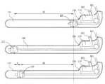
Translated fromKorean도 1은 본 발명에 따른 자동차용 버클 프리텐셔너 장치를 나타내는 개략적인 단면도,1 is a schematic cross-sectional view showing a buckle pretensioner device for automobiles according to the present invention;
도 2 및 도 3은 본 발명에 따른 자동차용 버클 프리텐셔너 장치의 추진롤러의 수평 단면도 및 수직 단면도,2 and 3 are a horizontal cross-sectional view and a vertical cross-sectional view of the propulsion roller of the buckle pretensioner device for automobiles according to the present invention,
도 4는 본 발명에 따른 자동차용 버클 프리텐셔너 장치의 작동상태를 나타내는 작동도,Figure 4 is an operation showing the operating state of the buckle pretensioner device for cars according to the present invention,
도 5는 본 발명에 따른 자동차용 버클 프리텐셔너 장치의 록킹수단의 작동상태를 나타내는 작동도,5 is an operation diagram showing an operating state of the locking means of the buckle pretensioner device for a vehicle according to the present invention,
도 6은 종래의 자동차용 버클 프리텐셔너 장치의 작동상태를 나타내는 작동도이다.6 is an operation diagram showing an operating state of a conventional vehicle buckle pretensioner device.
<도면의 주요 부분에 대한 부호의 설명><Explanation of symbols for the main parts of the drawings>
10 : 추진롤러11 : 기어부10: propulsion roller 11: gear part
15 : 작동체인20 : 가이드챔버부15: operation chain 20: guide chamber
21 : 기어부22 : 경사부21: gear portion 22: inclined portion
23 : 보관부25 : 볼부재23: storage 25: ball member
26 : 스프링30 : 뇌관26: spring 30: primer
31 : 기폭제
31: initiator
본 발명은 자동차용 버클 프리텐셔너 장치에 관한 것으로서, 더욱 상세하게 버클 몸체 및 추진부재를 연결수단을 통해 연결한 버클 프리텐셔너에 있어서, 상하 위치에 회전 가능한 기어부로 이루어진 추진부재가 차량의 추돌사고시 발생하는 발생가스에 의해 회전 및 직선 운동하여 일정 거리 이동할 경우, 상기 추진부재에 의해 당겨지는 연결수단인 작동체인의 길이가 상기 추진부재의 직선 작동거리에 비하여 월등한 길이로 당겨지게 될 뿐만 아니라, 경사진 형태의 구간을 탄성 이동하는 볼부재를 통해 상기 작동체인이 록킹되도록 하여 상기 추진부재가 작동하는 작동 구간을 줄일 수 있는 자동차용 버클 프리텐셔너 장치에 관한 것이다.The present invention relates to a buckle pretensioner device for automobiles, and more particularly, in a buckle pretensioner connecting a buckle body and a propulsion member through a connecting means, wherein a propulsion member formed of a gear part rotatable in an up and down position occurs during a collision of a vehicle. When moving by a certain distance by rotating and linear movement by gas, the length of the operating chain, which is a connecting means pulled by the propulsion member, is not only drawn to a superior length compared to the linear working distance of the propulsion member, but also inclined. It relates to a buckle pretensioner for a vehicle that can reduce the operating section of the propulsion member to operate by locking the operating chain through the ball member to elastically move the section of.
일반적으로, 버클 프리텐셔너는 충돌 발생시 시트벨트를 잡아 당겨 승객을 잡아줌으로써, 승객에게 발생할 수 있는 상해를 줄여주는 장치이다.In general, the buckle pretensioner is a device that reduces the injuries that may occur to the passenger by pulling the seat belt to pull the passenger in the event of a collision.
차량의 충돌이 발생하게 될 경우, 도 6에 도시된 바와 같이, 전기 신호가 뇌관(100)에 전해져 기폭제(101)를 점화시키며, 이를 통해 가스 발생기(110)에서 발생된 가스는 추진부재(120)를 밀어서 작동 와이어(130)를 끌게 된다.When a collision of the vehicle occurs, as shown in FIG. 6, an electrical signal is transmitted to the
이때, 작동 거리가 프리텐셔너의 몸통 길이에 따라 정해지면 적절한 성능을 발휘하기 위하여 작동구간이 상당히 길어지게 된다.At this time, if the working distance is determined according to the length of the body of the pretensioner, the operating section becomes considerably longer for proper performance.
초기 이동한 초기 작동 거리는 DI만큼이 되며, 승객의 전방으로의 관성 이동에 의하여 작동 와이어(130)가 끌려가면서 잠금구조에 의해 멈추는 부분을 고려할 경우, 실제 유효작동거리는 DE가 되며, 초기 작동거리 DI에서 감소거리 d를 뺀 값이 된다.The initial moving distance that is initially moved is DI, and when considering the part where the
그런데, 이러한 종래의 버클 프리텐셔너는 다른 리트렉터 프리텐셔나 장치나 랩 마운팅 프리텐셔너 장치에 비해 시트 및 콘솔박스와의 간섭과 같은 레이 아웃 상에 문제점이 있다.However, these conventional buckle pretensioners have problems with layouts such as interference with seats and console boxes compared to other retractor pretensioners or lap mounting pretensioners.
이와 같은 문제점을 해결하기 위해서는 비용 상승, 상품성 저하 및 설계지연 문제가 발생하게 되며, 도면에 도시된 바와 같이, 시트에 장착되는 버클 프리텐셔너의 가이드챔버부(140)는 긴 총열과 유사한 형상으로 되어 불쾌감 및 위협감을 주는 문제점이 있다.
In order to solve such a problem, a cost increase, a decrease in productability, and a design delay problem occur. As shown in the drawing, the
따라서, 본 발명은 상기와 같은 문제점을 해결하기 위해 발명한 것으로서, 버클 몸체 및 추진부재를 연결수단을 통해 연결한 버클 프리텐셔너에 있어서, 상하 위치에 회전 가능한 기어부로 이루어진 추진부재가 차량의 추돌사고시 발생하는 발생가스에 의해 회전 및 직선 운동하여 일정 거리 이동할 경우, 상기 추진부재에 의해 당겨지는 기존의 연결수단인 작동와이어를 작동체인으로 적용하며, 이 작동체인 이 상기 추진부재의 직선 작동거리에 비하여 월등한 길이로 당겨지게 될 뿐만 아니라, 경사진 형태의 구간을 탄성 이동하는 볼부재를 통해 상기 작동체인이 록킹되도록 하여 상기 추진부재가 이동할 수 있는 작동 구간을 줄일 수 있게 됨으로써, 레이 아웃 문제를 해결할 뿐만 아니라, 외관 개선을 통해 품질도 한단계 업그레이드 시킬 수 있으며, 작동체인의 작동거리 감소구간을 작게하여 승객의 안전 성능을 향상시킬 수 있는 자동차용 버클 프리텐셔너 장치를 제공하는데 그 목적이 있다.
Therefore, the present invention has been invented to solve the above problems, in the buckle pretensioner connecting the buckle body and the propulsion member through the connecting means, the propulsion member consisting of a gear portion that is rotatable in the vertical position occurs when a collision accident of the vehicle When moving a certain distance by rotating and linear movement by the generated gas to be applied, the operation wire which is a conventional connecting means pulled by the propulsion member is applied to the operation chain, the operation chain is higher than the straight working distance of the propulsion member As well as being pulled to one length, the operation chain is locked by the ball member which elastically moves the inclined section, thereby reducing the operation section in which the pushing member can move, thereby solving the layout problem. In addition, the quality can be upgraded by improving the appearance. It is an object of the present invention to provide a buckle pretensioner for automobiles that can improve the safety performance of passengers by reducing the operating distance reduction section of the operating chain.
이하, 상기와 같은 목적을 달성하기 위한 본 발명의 특징에 대해 설명하면 다음과 같다.Hereinafter, the features of the present invention for achieving the above object are as follows.
본 발명은, 뇌관 및 기폭제와, 상기 뇌관 및 기폭제의 폭발로 인한 발생가스의 압력을 통해 작동하는 추진부재와, 상기 추진부재가 일정 거리만큼 이동 가능하도록 안내하는 가이드챔버부와, 버클 몸체 및 상기 추진부재 사이에 연결된 연결수단을 포함하여 이루어진 자동차용 버클 프리텐셔너 장치에 있어서,The present invention, the primer and the initiator, the propulsion member to operate through the pressure of the gas generated by the explosion of the primer and the initiator, the guide chamber portion for guiding the propulsion member to be moved by a predetermined distance, the buckle body and the In the buckle pre-tensioner device for cars comprising a connecting means connected between the pushing member,
둘레면에 기어부가 형성되고, 상기 가이드챔버부의 상하 내측면에 형성된 기어부에 각각 치합되는 한 쌍의 원형부재인 추진롤러와;A propelling roller having a gear portion formed on a circumferential surface thereof and a pair of circular members respectively engaged with gear portions formed on upper and lower inner surfaces of the guide chamber portion;
상기 추진롤러에 치합되는 동시에 상기 버클 몸체에 연결되어 추진롤러에 의해 이동하면서 버클 몸체를 잡아당기는 작동체인을 포함하여 구성된 것을 특징으로 한다.It is characterized in that it is configured to include a working chain that is connected to the buckle body and is connected to the buckle body at the same time to be pushed by the pushing roller while pulling the buckle body.
특히, 상기 가이드챔버부는 그 일측 단부에 상기 추진롤러의 작동에 의해 당 겨진 작동체인이 보관되는 보관부와;In particular, the guide chamber portion and the storage portion is stored at one end of the operating chain pulled by the operation of the pushing roller;
상기 보관부와 인접한 부위에 보관되는 작동체인이 자동차의 추돌사고시 다시 인출되지 않도록 록킹하여 버클이 돌출되지 않도록 하는 록킹수단을 더 포함하는 것을 특징으로 한다.It is characterized in that it further comprises a locking means for locking the operating chain stored in the area adjacent to the storage so that the buckle does not protrude so as not to be pulled out again in the event of a car crash.
또한, 상기 록킹수단은 상기 가이드챔버부의 상하부에 구비된 경사진 형태의 경사부에 장착되어 작동체인의 초기 진행방향과 반대방향으로 탄성 작용하는 스프링이 고정된 볼부재인 것을 특징으로 한다.In addition, the locking means is mounted to the inclined portion of the inclined shape provided in the upper and lower portions of the guide chamber portion is characterized in that the ball member is fixed to the spring elastically acting in the opposite direction to the initial travel direction of the operating chain.
이하, 첨부도면을 참조하여 본 발명의 구성에 대해 상세하게 설명하면 다음과 같다.Hereinafter, the configuration of the present invention will be described in detail with reference to the accompanying drawings.
첨부한 도 1은 본 발명에 따른 자동차용 버클 프리텐셔너 장치를 나타내는 개략적인 단면도이고, 도 2 및 도 3은 본 발명에 따른 자동차용 버클 프리텐셔너 장치의 추진롤러의 수평 단면도 및 수직 단면도를 나타낸다.1 is a schematic cross-sectional view showing an automobile buckle pretensioner device according to the present invention, Figures 2 and 3 show a horizontal cross-sectional view and a vertical cross-sectional view of the propulsion roller of the buckle pretensioner device for cars according to the present invention.
또한, 도 4는 본 발명에 따른 자동차용 버클 프리텐셔너 장치의 작동상태를 나타내는 작동도이며, 도 5는 본 발명에 따른 자동차용 버클 프리텐셔너 장치의 록킹수단의 작동상태를 나타내는 작동도이다.4 is an operation diagram showing an operating state of the vehicle buckle pretensioner device according to the present invention, Figure 5 is an operation diagram showing an operating state of the locking means of the vehicle buckle pretensioner device according to the present invention.
도 1에 도시된 바와 같이, 뇌관(30) 및 기폭제(31)와, 상기 뇌관(30) 및 기폭제(31)의 폭발로 인한 가스 발생기(32)에서 발생된 발생가스의 압력을 통해 작동하는 추진부재(120)와, 상기 추진부재가 일정 거리만큼 이동 가능하도록 안내하는 가이드챔버부(20)와, 버클 몸체(미도시) 및 상기 추진부재 사이에 연결된 작동체인(15)을 포함하여 이루어진 자동차용 버클 프리텐셔너 장치에 있어서, 상기 추진부 재는 상기 뇌관(30) 및 기폭제(31)의 폭발로 인한 발생가스의 압력에 의해 작동하게 되며, 상기 가이드챔버부(20)의 상하 위치에 장착되어 있는 한 쌍의 원형부재로서, 그 둘레면에 기어부(11)가 형성되어 있으며, 가이드챔버부(20)의 상하 내측면에 형성된 기어부(21)에 치합되어 회전하면서, 직선 이동 가능토록 되어 있는 추진롤러(10)이다.As shown in FIG. 1, the propulsion operates through the pressure of the
한편, 상기 추진롤러(10) 각각의 기어부(11) 사이에는 그 기어부(11)와 치합되는 작동체인(15)이 삽입되어 있는 바, 상기 작동체인(15)은 추진롤러(10)의 기어부(11)에 맞물린 형태로 되어 상기 추진롤러(10)가 이동시 함께 이동 가능하도록 되어 있다.On the other hand, between the
상기 가이드챔버부(20)의 일측 단부에는 추진롤러(10)의 작동에 의해 당겨진 작동체인(15)이 보관되는 보관부(23)가 형성되어 있으며, 상기 보관부(23)와 인접한 부위에 보관되는 작동체인(15)이 자동차의 추돌사고시 다시 인출되지 않도록 록킹하여 버클이 돌출되지 않도록 하는 록킹수단이 형성되어 있다.At one end of the
상기 록킹수단은 상기 작동체인(15)의 초기 진행방향과 반대방향으로 탄성 작용하는 탄성수단인 스프링(26)이 일측에 고정된 볼부재(25)로 이루어져 있으며, 상기 볼부재(25)는 탄성 작용하는 방향으로 경사진 형태로 상기 가이드챔버부(20)의 상하부에 구비된 경사부(22)에 장착되어 있다.The locking means is composed of a
이때, 상기 추진롤러(10)의 작동에 의해 작동체인(15)이 보관부(23)쪽으로 당겨져 있는 동안에는 그 작동체인(15)의 작용에 의해 볼부재(25)가 경사면의 낮은 곳에 위치함에 따라 작동체인(15)의 작동에 영향을 미치지 않게 된다.At this time, while the
이하, 상기와 같은 구성을 갖는 본 발명의 작동원리에 대하여 설명하면 다음과 같다.Hereinafter, the operation principle of the present invention having the configuration as described above are as follows.
먼저, 자동차의 추돌사고시, 뇌관(30) 및 기폭제(31)의 폭발작용에 의해 발생하는 발생가스의 압력을 통해 추진롤러(10)가 작동체인(15)을 보관부(23)쪽으로 완전히 당겨지도록 하는 바, 상기 추진롤러(10)에 형성된 기어부(11)와, 이와 치합된 가이드챔버부(20)의 상하 위치에 형성된 기어부(21)를 통해, 추진롤러(10)가 회전하면서 직선 이동하여 진행하게 된다.
즉, 위아래 2개의 추진롤러(10)가 그 사이의 작동체인(15)을 매개로 물려서 지지되는 상태이므로, 도 4에서 추진롤러(10)의 오른쪽에 발생가스에 의한 압력하중이 부과되면, 가이드챔버부(20)는 고정단 역할을 하게 되고, 중앙의 체인 부분은 자유단 역할을 하게 되어, 2개의 추진롤러(10)가 체인과 맞물려 있는 중앙의 자유단쪽으로 회전하면서 이동이 가능하게 되는 것이다.First, in the event of a collision of the vehicle, the
That is, since the two
이때, 각각의 상기 추진롤러(10)의 기어부(11) 사이에 맞물린 상태로 삽입되어 있는 작동체인(15)은, 상기 추진롤러(10)에 형성된 기어부(11)의 회전운동에 의한 이동거리와 직선 운동에 의한 이동거리를 더한 만큼 이동하게 된다.At this time, the
이로써, 상기 추진롤러(10)의 이동거리와 비교하여 상기 작동체인(15)의 이동거리가 충분히 확보되므로 본 발명에 따른 가이드챔버부(20)의 길이를 종래의 버클 프리텐셔너와 동일한 스트롤 하에 짧은 가이드챔버부(20)가 가능하게 된다.Thus, the moving distance of the
이와 같이, 상기 추진롤러(10)의 회전운동 및 직선운동을 통해 보관부(23)로 당겨진 작동체인(15)은 권입이 완료된 상태에서, 다시 승객의 관성작용에 의한 시트벨트의 작용에 의해 다시 작동체인(15)이 초기 상태로 복귀할 경우, 상기 작동체인(15)의 작용방향과 스프링(26)의 작용방향이 같아지게 됨에 따라 볼부재(25)는 경사면을 따라 높은 곳으로 이동하게 되어 작동체인(15)면 및 경사부(22)의 경사면에 끼이게 되어 작동체인(15)을 고정시키게 된다.In this way, the
이로써, 시트벨트의 작용력이 승객에게 전달되고, 이로인해 승객은 적절하게 보호된다.
In this way, the seat belt forces are transmitted to the passenger, thereby protecting the passenger appropriately.
상술한 바와 같이, 본 발명에 따른 자동차용 버클 프리텐셔너 장치에 의하면, 추진부재의 작동구간 축소를 통해 시트 및 콘솔박스 등과의 간섭 문제를 최소화하여 비용 절감 및 설계지연 방지를 도모할 뿐만 아니라, 외관 개선을 통해 자동차의 품질도 한단계 높일 수 있다.As described above, according to the buckle pre-tensioner device for automobiles according to the present invention, by reducing the operating period of the propulsion member to minimize the interference problem with the seat and the console box, etc., not only to reduce cost and prevent design delay, but also improve the appearance Through this, the quality of the car can also be improved.
또한, 추진롤러의 추진력 확보 및 작동체인의 작동거리 감소구간을 작게하여 승객의 안전 성능을 향상시키는 효과가 있다.In addition, it is effective in securing the driving force of the propulsion roller and reducing the operating distance reduction section of the operation chain to improve the safety performance of the passenger.
Claims (3)
Translated fromKoreanPriority Applications (1)
| Application Number | Priority Date | Filing Date | Title |
|---|---|---|---|
| KR1020040097751AKR100986420B1 (en) | 2004-11-26 | 2004-11-26 | Automotive buckle pretensioner device |
Applications Claiming Priority (1)
| Application Number | Priority Date | Filing Date | Title |
|---|---|---|---|
| KR1020040097751AKR100986420B1 (en) | 2004-11-26 | 2004-11-26 | Automotive buckle pretensioner device |
Publications (2)
| Publication Number | Publication Date |
|---|---|
| KR20060058804A KR20060058804A (en) | 2006-06-01 |
| KR100986420B1true KR100986420B1 (en) | 2010-10-08 |
Family
ID=37156180
Family Applications (1)
| Application Number | Title | Priority Date | Filing Date |
|---|---|---|---|
| KR1020040097751AExpired - Fee RelatedKR100986420B1 (en) | 2004-11-26 | 2004-11-26 | Automotive buckle pretensioner device |
Country Status (1)
| Country | Link |
|---|---|
| KR (1) | KR100986420B1 (en) |
Citations (4)
| Publication number | Priority date | Publication date | Assignee | Title |
|---|---|---|---|---|
| JPH0672285A (en)* | 1992-08-31 | 1994-03-15 | Tachi S Co Ltd | Through guide structure of seat belt |
| US5839686A (en) | 1995-10-12 | 1998-11-24 | Alliedsignal Inc. | Chain driven pretensioner and retractor |
| US6308986B1 (en) | 1999-04-16 | 2001-10-30 | Joalto Design, Inc. | Restraint belt presenter |
| KR20070017115A (en)* | 2006-07-24 | 2007-02-08 | 오토리브 아이에프비 인디아 피브이티 리미티드 | Pretensioners and pretensioning methods with chained operating bodies |
- 2004
- 2004-11-26KRKR1020040097751Apatent/KR100986420B1/ennot_activeExpired - Fee Related
Patent Citations (4)
| Publication number | Priority date | Publication date | Assignee | Title |
|---|---|---|---|---|
| JPH0672285A (en)* | 1992-08-31 | 1994-03-15 | Tachi S Co Ltd | Through guide structure of seat belt |
| US5839686A (en) | 1995-10-12 | 1998-11-24 | Alliedsignal Inc. | Chain driven pretensioner and retractor |
| US6308986B1 (en) | 1999-04-16 | 2001-10-30 | Joalto Design, Inc. | Restraint belt presenter |
| KR20070017115A (en)* | 2006-07-24 | 2007-02-08 | 오토리브 아이에프비 인디아 피브이티 리미티드 | Pretensioners and pretensioning methods with chained operating bodies |
Also Published As
| Publication number | Publication date |
|---|---|
| KR20060058804A (en) | 2006-06-01 |
Similar Documents
| Publication | Publication Date | Title |
|---|---|---|
| EP1266792B1 (en) | Vehicle occupant side crash protection system | |
| JP4133059B2 (en) | Vehicle seat having a front movable headrest | |
| US10562490B2 (en) | Occupant restraining device for vehicle | |
| EP2492158B1 (en) | Seat belt assembly | |
| JP2012071834A (en) | Safety device | |
| CN111183058B (en) | Vehicle with passenger protection system having increased free space available in the vehicle interior | |
| US9333944B2 (en) | Anchor pretensioner for vehicle | |
| EP1106480B1 (en) | Occupant protective apparatus | |
| KR100986420B1 (en) | Automotive buckle pretensioner device | |
| KR101199715B1 (en) | anti-submarine seat for an automobile | |
| KR102634408B1 (en) | Seat belt for protecting submarine accident in automobile and operating method thereof | |
| KR100513743B1 (en) | Retractor device of seatbelt for automobile | |
| JP2003025939A (en) | Occupant protection device | |
| JP4350252B2 (en) | Seat belt device | |
| JP2000326823A (en) | Seat belt equipment | |
| JP2013014291A (en) | Seat belt apparatus | |
| JP4272090B2 (en) | Crew protection device | |
| KR100435382B1 (en) | Loadlimiter for automobile | |
| US10583800B2 (en) | Occupant protection device | |
| KR100369028B1 (en) | Sliding guide plate of parts for vehicle | |
| JP2018058564A (en) | Vehicular occupant restraint device | |
| KR100427275B1 (en) | Structure of pretensioner for automobile | |
| KR100447317B1 (en) | The seat structure for moving backward | |
| JP4311221B2 (en) | Movable bumper device | |
| KR100349749B1 (en) | Device for cutting seatbelt for automobile |
Legal Events
| Date | Code | Title | Description |
|---|---|---|---|
| PA0109 | Patent application | St.27 status event code:A-0-1-A10-A12-nap-PA0109 | |
| PG1501 | Laying open of application | St.27 status event code:A-1-1-Q10-Q12-nap-PG1501 | |
| R18-X000 | Changes to party contact information recorded | St.27 status event code:A-3-3-R10-R18-oth-X000 | |
| A201 | Request for examination | ||
| PA0201 | Request for examination | St.27 status event code:A-1-2-D10-D11-exm-PA0201 | |
| D13-X000 | Search requested | St.27 status event code:A-1-2-D10-D13-srh-X000 | |
| D14-X000 | Search report completed | St.27 status event code:A-1-2-D10-D14-srh-X000 | |
| E902 | Notification of reason for refusal | ||
| PE0902 | Notice of grounds for rejection | St.27 status event code:A-1-2-D10-D21-exm-PE0902 | |
| PN2301 | Change of applicant | St.27 status event code:A-3-3-R10-R13-asn-PN2301 St.27 status event code:A-3-3-R10-R11-asn-PN2301 | |
| P11-X000 | Amendment of application requested | St.27 status event code:A-2-2-P10-P11-nap-X000 | |
| P13-X000 | Application amended | St.27 status event code:A-2-2-P10-P13-nap-X000 | |
| R17-X000 | Change to representative recorded | St.27 status event code:A-3-3-R10-R17-oth-X000 | |
| E90F | Notification of reason for final refusal | ||
| PE0902 | Notice of grounds for rejection | St.27 status event code:A-1-2-D10-D21-exm-PE0902 | |
| P11-X000 | Amendment of application requested | St.27 status event code:A-2-2-P10-P11-nap-X000 | |
| P13-X000 | Application amended | St.27 status event code:A-2-2-P10-P13-nap-X000 | |
| E701 | Decision to grant or registration of patent right | ||
| PE0701 | Decision of registration | St.27 status event code:A-1-2-D10-D22-exm-PE0701 | |
| GRNT | Written decision to grant | ||
| PR0701 | Registration of establishment | St.27 status event code:A-2-4-F10-F11-exm-PR0701 | |
| PR1002 | Payment of registration fee | St.27 status event code:A-2-2-U10-U11-oth-PR1002 Fee payment year number:1 | |
| PG1601 | Publication of registration | St.27 status event code:A-4-4-Q10-Q13-nap-PG1601 | |
| PN2301 | Change of applicant | St.27 status event code:A-5-5-R10-R13-asn-PN2301 St.27 status event code:A-5-5-R10-R11-asn-PN2301 | |
| FPAY | Annual fee payment | Payment date:20130927 Year of fee payment:4 | |
| PR1001 | Payment of annual fee | St.27 status event code:A-4-4-U10-U11-oth-PR1001 Fee payment year number:4 | |
| FPAY | Annual fee payment | Payment date:20140929 Year of fee payment:5 | |
| PR1001 | Payment of annual fee | St.27 status event code:A-4-4-U10-U11-oth-PR1001 Fee payment year number:5 | |
| FPAY | Annual fee payment | Payment date:20150930 Year of fee payment:6 | |
| PR1001 | Payment of annual fee | St.27 status event code:A-4-4-U10-U11-oth-PR1001 Fee payment year number:6 | |
| R17-X000 | Change to representative recorded | St.27 status event code:A-5-5-R10-R17-oth-X000 | |
| R18-X000 | Changes to party contact information recorded | St.27 status event code:A-5-5-R10-R18-oth-X000 | |
| P22-X000 | Classification modified | St.27 status event code:A-4-4-P10-P22-nap-X000 | |
| PR1001 | Payment of annual fee | St.27 status event code:A-4-4-U10-U11-oth-PR1001 Fee payment year number:7 | |
| LAPS | Lapse due to unpaid annual fee | ||
| PC1903 | Unpaid annual fee | St.27 status event code:A-4-4-U10-U13-oth-PC1903 Not in force date:20171002 Payment event data comment text:Termination Category : DEFAULT_OF_REGISTRATION_FEE | |
| PC1903 | Unpaid annual fee | St.27 status event code:N-4-6-H10-H13-oth-PC1903 Ip right cessation event data comment text:Termination Category : DEFAULT_OF_REGISTRATION_FEE Not in force date:20171002 | |
| R18-X000 | Changes to party contact information recorded | St.27 status event code:A-5-5-R10-R18-oth-X000 |