KR100985924B1 - Electrodialysis water purifier with ion exchange material and how to remove ion pollutants - Google Patents
Electrodialysis water purifier with ion exchange material and how to remove ion pollutantsDownload PDFInfo
- Publication number
- KR100985924B1 KR100985924B1KR1020047014311AKR20047014311AKR100985924B1KR 100985924 B1KR100985924 B1KR 100985924B1KR 1020047014311 AKR1020047014311 AKR 1020047014311AKR 20047014311 AKR20047014311 AKR 20047014311AKR 100985924 B1KR100985924 B1KR 100985924B1
- Authority
- KR
- South Korea
- Prior art keywords
- ion exchange
- anion
- cation
- flow
- flow channel
- Prior art date
- Legal status (The legal status is an assumption and is not a legal conclusion. Google has not performed a legal analysis and makes no representation as to the accuracy of the status listed.)
- Expired - Fee Related
Links
Images


Classifications
- C—CHEMISTRY; METALLURGY
- C02—TREATMENT OF WATER, WASTE WATER, SEWAGE, OR SLUDGE
- C02F—TREATMENT OF WATER, WASTE WATER, SEWAGE, OR SLUDGE
- C02F1/00—Treatment of water, waste water, or sewage
- C02F1/46—Treatment of water, waste water, or sewage by electrochemical methods
- C02F1/469—Treatment of water, waste water, or sewage by electrochemical methods by electrochemical separation, e.g. by electro-osmosis, electrodialysis, electrophoresis
- C02F1/4693—Treatment of water, waste water, or sewage by electrochemical methods by electrochemical separation, e.g. by electro-osmosis, electrodialysis, electrophoresis electrodialysis
- C02F1/4695—Treatment of water, waste water, or sewage by electrochemical methods by electrochemical separation, e.g. by electro-osmosis, electrodialysis, electrophoresis electrodialysis electrodeionisation
- C—CHEMISTRY; METALLURGY
- C02—TREATMENT OF WATER, WASTE WATER, SEWAGE, OR SLUDGE
- C02F—TREATMENT OF WATER, WASTE WATER, SEWAGE, OR SLUDGE
- C02F1/00—Treatment of water, waste water, or sewage
- C02F1/42—Treatment of water, waste water, or sewage by ion-exchange
- B—PERFORMING OPERATIONS; TRANSPORTING
- B01—PHYSICAL OR CHEMICAL PROCESSES OR APPARATUS IN GENERAL
- B01D—SEPARATION
- B01D61/00—Processes of separation using semi-permeable membranes, e.g. dialysis, osmosis or ultrafiltration; Apparatus, accessories or auxiliary operations specially adapted therefor
- B01D61/42—Electrodialysis; Electro-osmosis ; Electro-ultrafiltration; Membrane capacitive deionization
- B01D61/44—Ion-selective electrodialysis
- B01D61/46—Apparatus therefor
- B01D61/48—Apparatus therefor having one or more compartments filled with ion-exchange material, e.g. electrodeionisation
- B—PERFORMING OPERATIONS; TRANSPORTING
- B01—PHYSICAL OR CHEMICAL PROCESSES OR APPARATUS IN GENERAL
- B01D—SEPARATION
- B01D61/00—Processes of separation using semi-permeable membranes, e.g. dialysis, osmosis or ultrafiltration; Apparatus, accessories or auxiliary operations specially adapted therefor
- B01D61/42—Electrodialysis; Electro-osmosis ; Electro-ultrafiltration; Membrane capacitive deionization
- B01D61/44—Ion-selective electrodialysis
- B01D61/52—Accessories; Auxiliary operation
- B—PERFORMING OPERATIONS; TRANSPORTING
- B01—PHYSICAL OR CHEMICAL PROCESSES OR APPARATUS IN GENERAL
- B01J—CHEMICAL OR PHYSICAL PROCESSES, e.g. CATALYSIS OR COLLOID CHEMISTRY; THEIR RELEVANT APPARATUS
- B01J47/00—Ion-exchange processes in general; Apparatus therefor
- B01J47/02—Column or bed processes
- B01J47/06—Column or bed processes during which the ion-exchange material is subjected to a physical treatment, e.g. heat, electric current, irradiation or vibration
- B01J47/08—Column or bed processes during which the ion-exchange material is subjected to a physical treatment, e.g. heat, electric current, irradiation or vibration subjected to a direct electric current
- C—CHEMISTRY; METALLURGY
- C02—TREATMENT OF WATER, WASTE WATER, SEWAGE, OR SLUDGE
- C02F—TREATMENT OF WATER, WASTE WATER, SEWAGE, OR SLUDGE
- C02F1/00—Treatment of water, waste water, or sewage
- C02F1/46—Treatment of water, waste water, or sewage by electrochemical methods
- C02F1/4604—Treatment of water, waste water, or sewage by electrochemical methods for desalination of seawater or brackish water
- C—CHEMISTRY; METALLURGY
- C02—TREATMENT OF WATER, WASTE WATER, SEWAGE, OR SLUDGE
- C02F—TREATMENT OF WATER, WASTE WATER, SEWAGE, OR SLUDGE
- C02F2103/00—Nature of the water, waste water, sewage or sludge to be treated
- C02F2103/02—Non-contaminated water, e.g. for industrial water supply
- C02F2103/04—Non-contaminated water, e.g. for industrial water supply for obtaining ultra-pure water
- C—CHEMISTRY; METALLURGY
- C02—TREATMENT OF WATER, WASTE WATER, SEWAGE, OR SLUDGE
- C02F—TREATMENT OF WATER, WASTE WATER, SEWAGE, OR SLUDGE
- C02F2201/00—Apparatus for treatment of water, waste water or sewage
- C02F2201/46—Apparatus for electrochemical processes
- C02F2201/461—Electrolysis apparatus
- C02F2201/46105—Details relating to the electrolytic devices
- C02F2201/46115—Electrolytic cell with membranes or diaphragms
- C—CHEMISTRY; METALLURGY
- C02—TREATMENT OF WATER, WASTE WATER, SEWAGE, OR SLUDGE
- C02F—TREATMENT OF WATER, WASTE WATER, SEWAGE, OR SLUDGE
- C02F2201/00—Apparatus for treatment of water, waste water or sewage
- C02F2201/46—Apparatus for electrochemical processes
- C02F2201/461—Electrolysis apparatus
- C02F2201/46105—Details relating to the electrolytic devices
- C02F2201/4612—Controlling or monitoring
- C02F2201/46125—Electrical variables
- Y—GENERAL TAGGING OF NEW TECHNOLOGICAL DEVELOPMENTS; GENERAL TAGGING OF CROSS-SECTIONAL TECHNOLOGIES SPANNING OVER SEVERAL SECTIONS OF THE IPC; TECHNICAL SUBJECTS COVERED BY FORMER USPC CROSS-REFERENCE ART COLLECTIONS [XRACs] AND DIGESTS
- Y10—TECHNICAL SUBJECTS COVERED BY FORMER USPC
- Y10S—TECHNICAL SUBJECTS COVERED BY FORMER USPC CROSS-REFERENCE ART COLLECTIONS [XRACs] AND DIGESTS
- Y10S210/00—Liquid purification or separation
- Y10S210/90—Ultra pure water, e.g. conductivity water
Landscapes
- Chemical & Material Sciences (AREA)
- Engineering & Computer Science (AREA)
- Water Supply & Treatment (AREA)
- Chemical Kinetics & Catalysis (AREA)
- Health & Medical Sciences (AREA)
- Life Sciences & Earth Sciences (AREA)
- Organic Chemistry (AREA)
- Urology & Nephrology (AREA)
- Environmental & Geological Engineering (AREA)
- Hydrology & Water Resources (AREA)
- Electrochemistry (AREA)
- General Chemical & Material Sciences (AREA)
- Molecular Biology (AREA)
- Analytical Chemistry (AREA)
- Separation Using Semi-Permeable Membranes (AREA)
- Water Treatment By Electricity Or Magnetism (AREA)
Abstract
Translated fromKorean
Description
Translated fromKorean본 발명은 특히 전류 효율적인 방식으로 정수하는 방법 및 정수 장치에 관한 것이다.The present invention relates in particular to a method and a water purification device for purifying in a current efficient manner.
정제된 탈이온(DI)수는 많은 분석학적 적용, 예를 들어 온라인 또는 오프라인 용리액을 제조하기 위한 이온 크로마토그래피 및 크로마토그래피, 자동 샘플채취기를 사용한 샘플 제조 적용 및 다양한 일상의 실험실 사용에서 사용된다. 정제된 탈이온수를 제조하기 위해 여러가지 전기투석 방법이 사용되어 왔다.Purified deionized (DI) water is used in many analytical applications, for example ion chromatography and chromatography for the preparation of on-line or off-line eluents, sample preparation applications using automated samplers, and various routine laboratory uses. Various electrodialysis methods have been used to produce purified deionized water.
문헌에 기재된 전기투석은, 양이온 교환막과 음이온 교환막을 수돗물, 염수 또는 반염수를 정수하기 위한 전기장과 함께 사용할 경우 사용되는 용어이다. "전기탈이온화"는 상기 방법에서 이온 교환 물질의 용도를 기술하기 위해 사용되는 용어이다. 다수의 특허들이 다양한 이온 교환 물질 및 배치를 사용한 상기 방법에 대해 논의하고 있다.Electrodialysis described in the literature is a term used when a cation exchange membrane and an anion exchange membrane are used together with an electric field for purifying tap water, brine or hemi brine. "Electrodeionization" is a term used to describe the use of ion exchange materials in the process. A number of patents discuss this method using various ion exchange materials and batches.
전기투석에 의해 액체를 처리하는 초기 장치 및 방법은 미국 특허 제2,689,826호에서 콜즈만(Kollsman)에 의해 기재되었다. 이 장치는 장치의 말단 측면에 위치하는 전극과 직렬로 배치된 음이온 및 양이온 교환 격판을 함유하였다. 처리될 액체의 일 부피를 고갈(정제) 챔버에 놓으면 이온들이 시간이 경과함에 따라 당해 부피에서 농축 챔버에서의 제2의 부피의 액체로 이동한다. 따라서 처리된 액체는 이온이 고갈되고 농축 챔버내의 액체에는 이송된 이온이 풍부해진다. 미국 특허 제2,794,777호는 각각 음이온 및 양이온 격판에 인접한 챔버에 흐르는 산 및 염기 용액을 사용한 유사 구조의 장치를 기술하였다. 당해 산 및 염기 용액의 기능은 전도 경로를 제공하여 저항을 줄이는 것이었다. 당해 음이온 및 양이온 교환 격판은 천으로 제조되고 각각의 수지 물질로 충전된 벽이었다. 부분적 이온화가 다른 충전된 베드 컬럼과 함께 당해 장치를 사용하여 달성되었다.An initial apparatus and method for treating liquids by electrodialysis was described by Kollsman in US Pat. No. 2,689,826. The device contained anion and cation exchange diaphragms disposed in series with the electrode located on the terminal side of the device. Placing one volume of liquid to be treated in the depletion (purification) chamber causes ions to migrate from that volume to the second volume of liquid in the concentration chamber over time. The treated liquid is thus depleted of ions and the liquid in the concentration chamber is rich in transported ions. US Pat. No. 2,794,777 describes a similarly structured device using acid and base solutions flowing in chambers adjacent to anionic and cationic diaphragms, respectively. The function of these acid and base solutions was to provide a conductive pathway to reduce resistance. The anion and cation exchange diaphragms were walls made of cloth and filled with the respective resinous materials. Partial ionization was achieved using this apparatus with other packed bed columns.
미국 특허 제2,815,320호는 저항을 줄이고 전도 경로를 유지하기 위해 선택적투과 음이온 및 양이온 교환 막 사이에 충전재로서 거대다공성 이온 교환 비즈들 사용하는 장치를 기술하였다. 전해질이 전극 챔버에서 순환될 수 있다고 제안된다. 당해 특허에 따르면, 전극 챔버내의 전해질, 및 중간체 챔버내의 전도성 충전재가 전류 수송을 위한 전도 경로를 제공하였다. 미국 특허 제2,923,674호는 이온의 제거를 촉진시켜 물 스트림을 정제하는 다중 음이온 및 양이온 교환 처리 챔버를 갖는 유사한 전기투석 장치를 기술하였다. 상기 장치는 또한 특정의 챔버내에서 산 전해질을 사용하였다.US Pat. No. 2,815,320 describes a device using macroporous ion exchange beads as filler between a selective permeation anion and a cation exchange membrane to reduce resistance and maintain a conductive path. It is proposed that the electrolyte can be circulated in the electrode chamber. According to this patent, the electrolyte in the electrode chamber, and the conductive filler in the intermediate chamber, provided a conductive path for current transport. US Pat. No. 2,923,674 describes a similar electrodialysis apparatus having multiple anion and cation exchange treatment chambers that promote removal of ions to purify the water stream. The apparatus also used acid electrolytes in certain chambers.
미국 특허 제3,149,061호는 수용액으로부터 강하게 및 약하게 이온화되는 부류 둘 모두를 제거하는데 유용한 장치를 기술하였다. 당해 장치의 희석(정제) 챔버는 양이온과 음이온 교환 수지의 혼합물 또는 음이온 교환 수지 단독으로 충전되었다. 미국 특허 제3,341,441호는, 전극 챔버 내에서의 스케일 침착을 최소화시키기 위해 적용된 극성을 주기적으로 역전시키는 전기투석 방법을 기술하였다.U. S. Patent No. 3,149, 061 describes a device useful for removing both strongly and weakly ionized classes from aqueous solutions. The dilution (purification) chamber of the apparatus was filled with a mixture of cation and anion exchange resin or anion exchange resin alone. U.S. Patent No. 3,341,441 describes an electrodialysis method that periodically reverses the polarity applied to minimize scale deposition in the electrode chamber.
미국 특허 제3,869,376호는 연수를 탈염화하는데 유용한 장치를 기술하였다. 이들 장치에서의 처리 챔버는 이온 교환 수지로 충전되었다.U.S. Patent No. 3,869,376 describes a device useful for desalting soft water. The processing chambers in these devices were filled with ion exchange resins.
미국 특허 제4,148,708호는 애노드 및 캐소드 구획을 음이온 교환 및 양이온 교환 수지 각각으로 충전시키면서 공급 구획에서의 혼합된 음이온 및 양이온 교환 수지로 충전된 전기투석 전지를 기술하였다. 당해 전지는 당해 세개의 챔버로부터 산, 염기 및 정제수를 생성시키는데 유용하였다.US Pat. No. 4,148,708 describes an electrodialysis cell filled with mixed anion and cation exchange resin in the feed compartment while charging the anode and cathode compartments with anion exchange and cation exchange resin, respectively. The cell was useful for producing acid, base and purified water from the three chambers.
미국 특허 제4,632,745호는 고갈 챔버가 혼합된 음이온 및 양이온 교환 수지로 충전되어 있는 반면 농축 챔버에는 이온 교환 수지가 없는 전기탈이온화 장치를 기술하였다. 유사하게, 미국 특허 제4,925,541호는 고갈 챔버가 음이온 및 양이온 교환 수지 비즈로 충전되어 있는 반면 농축 구획에는 이온 교환 비즈가 없는 전기탈이온화 장치를 기술하였다. 고갈 구획내의 비즈는 조절된 폭 및 두께의 서브구획내에 수용되고 이온 투과성 막에 의해 그 안에 유지되는데, 이는 서브구획의 벽에 의해 고정되어 있었다. 상기 장치의 다른 형태는 미국 특허 제4,931,160호에 나타나 있는데, 여기서 정제될 액체는 음이온 및 양이온 교환 수지 비즈로 충전된 적어도 두 개의 이온 고갈 구획을 통과하였다. 미국 특허 제4,956,071호는 이온 교환 수지 비즈로 충전된 농축 챔버 및 고갈 챔버 둘 모두를 갖는 전기탈이온화 장치를 기술하였다. 당해 특허는 적용된 극성을 역전시키는 수단 및 정제 생성물을 연속하여 회수하는 수단을 기술한다. 미국 특허 제5,154,809호는 고갈 챔버 및 가능하게는 균일한 크기의 혼합된 이온 교환 비즈로 충전된 농축 챔버를 갖는 전기탈이온화 장치를 기술하였다.U. S. Patent No. 4,632, 745 describes an electrodeionization apparatus in which the depletion chamber is filled with mixed anion and cation exchange resin, while the concentration chamber is free of ion exchange resin. Similarly, US Pat. No. 4,925,541 describes an electrodeionization apparatus in which the depletion chamber is filled with anion and cation exchange resin beads while the concentration compartment is free of ion exchange beads. Beads in the depletion compartment were accommodated in a subcompartment of controlled width and thickness and held therein by an ion permeable membrane, which was held by the walls of the subcompartment. Another form of such a device is shown in US Pat. No. 4,931,160 wherein the liquid to be purified has passed through at least two ion depletion compartments filled with anion and cation exchange resin beads. US Pat. No. 4,956,071 describes an electrodeionization apparatus having both a concentration chamber and a depletion chamber filled with ion exchange resin beads. The patent describes a means for reversing the applied polarity and a means for continuously recovering the purified product. U. S. Patent No. 5,154, 809 describes an electrodeionization apparatus having a depletion chamber and possibly a concentration chamber filled with mixed ion exchange beads of possibly uniform size.
미국 특허 제5,308,466호는 더 낮은 가교 결합 및 더 낮은 선택성의 이온 교환 막/수지를 갖는 장치의 하나 이상의 섹션이 있어 전기 저항을 감소시키고, 공급수로부터 다량의, 수화가 많이 되고, 많이 또는 적게 대전된 분자(예: 실리카)를 용이하게 제거하는 장치를 기술하였다. 미국 특허 제5,308,467호는 탈염화 또는 희석 구획에 충전재로서 혼합된 이온 교환 성분(음이온 및 양이온 교환)으로 방사선 그래프팅된 중합체를 사용하는 전기탈이온화기를 기술하였다.U.S. Patent No. 5,308,466 has one or more sections of the device having lower crosslinks and lower selectivity of ion exchange membranes / resins to reduce electrical resistance, and to produce large, hydrated, high or low charge from the feed water. An apparatus for the easy removal of broken molecules (eg silica) is described. US Pat. No. 5,308,467 describes an electrodeionizer using a polymer grafted with ion exchange components (anion and cation exchange) mixed as filler in a desalting or dilution compartment.
미국 특허 제5,736,023호는 고갈 및 농축 챔버 둘 모두에 이온 교환 수지를 갖는 전기탈이온화 장치를 기술하였다. 당해 장치는 이온 고갈 구획에서의 흐름을 유지하면서 이온 농축 구획내의 액체를 더 낮은 이온 농도의 액체로 대체하는 수단 및 극성 역전 수단을 가진다. 미국 특허 제5,868,915호는 고갈 및 농축 구획에 전기활성 매질을 사용하는 전기탈이온화 장치를 기술하였다. 전기탈이온화 장치 및 방법에 대한 개선을 기술하는 수개의 다른 특허들이 있는데, 예를 들어, 미국 특허 제6,117,927호, 제6,126,805호, 제6,254,753호, 제6,241,866호, 제6,241,867호 및 6,312,577호이다.U.S. Patent 5,736,023 describes an electrodeionization apparatus having ion exchange resins in both depletion and concentration chambers. The apparatus has means for replacing the liquid in the ion concentration compartment with liquid of lower ion concentration and polarity reversal means while maintaining the flow in the ion depletion compartment. U.S. Patent 5,868,915 describes an electrodeionization apparatus using electroactive media in depletion and concentration compartments. There are several other patents describing improvements to electrodeionization devices and methods, for example, US Pat. Nos. 6,117,927, 6,126,805, 6,254,753, 6,241,866, 6,241,867 and 6,312,577.
상기에 기재한 모든 장치는 탈이온화 방법에 대한 이론으로부터 예측되는 것보다 과량의 전류를 필요로 하는 전류 비효율 장치이다. 고갈 챔버내에 혼합된 교환 충전재를 갖는 장치가 물을 분해하므로 전류 비효율적이다.All of the devices described above are current inefficient devices that require excess current than would be expected from the theory of the deionization method. Devices with exchange fillers mixed in the depletion chamber decompose water, making the current inefficient.
미국 특허 제6,077,434호 및 제6,328,885호는 이온 크로마토그래피에서 억제 기 및 억제기 유사 장치에 대한 전류 효율을 개선시키는 수단을 기술하였다. 음이온 분석용으로 기술된 장치는 양이온을 제거하고 매트릭스 이온을, 모든 음이온 성분들을 전도성 산으로 전환시키면서 비전도성 형태로 전환시킨다.US Pat. Nos. 6,077,434 and 6,328,885 describe means for improving the current efficiency for inhibitors and inhibitor like devices in ion chromatography. The device described for anion analysis removes cations and converts matrix ions into nonconductive form while converting all anion components to conductive acids.
이온 크로마토크로피에서, 수중 이온 불순물의 존재는 피크 반응 및 민감도, 반응 선형성, 백그라운드 안정성 및 베이스라인 소음에 영향을 미칠 수 있다. 소비재, 예를 들어 컬럼 및 억제기의 수명 또한 오염물질의 존재로 인해 방해받을 수 있다.In ion chromatography, the presence of ionic impurities in water can affect peak reactions and sensitivity, reaction linearity, background stability and baseline noise. The lifetime of consumer goods, such as columns and suppressors, can also be hampered by the presence of contaminants.
용리액이나 시약 중의 오염물질과 관련된 몇몇 문제는 인정된 수준의 오염물질과 함께 초고순도 순수 시약을 사용하여 해소될 수 있다. 분석 실험실은 탈이온수내의 이온 오염물질 수준을 감소시키고자 하는 연마제(polisher) 시스템의 사용 문제를 갖는다. 그러나, 이들 시스템에서는 연마제의 대체가 요구되지 않는다. 대부분의 시스템에서의 수질 탐지는 또한 신뢰성이 없다. 용리액이나 시약 제조를 위한 인증된 병에 담긴 생수를 사용하는 것도 다른 방법이다. 그러나, 이러한 방법은 환경으로부터 오염을 제한하는데 어려움이 있고, 취급 문제, 저장 수명 및 비용이 더 든다는 문제가 있다. 또한, 시약 제조 공정 동안에 이산화탄소 및 암모니아와 같은 특정의 오염물질을 제거하는 것이 곤란하다.Some problems with contaminants in eluents or reagents can be solved using ultra-pure pure reagents with recognized levels of contaminants. Analytical laboratories have the problem of using a polishing system to reduce the level of ionic contaminants in deionized water. However, replacement of abrasives is not required in these systems. Water quality detection in most systems is also unreliable. Another option is to use bottled water in a certified bottle to prepare the eluent or reagent. However, this method has difficulty in limiting contamination from the environment and has a problem of handling problem, shelf life and cost. It is also difficult to remove certain contaminants such as carbon dioxide and ammonia during the reagent preparation process.
상기에서 논의된 인자들의 알짜 효과는 실험실마다 수질이 다르다는데 있다. 따라서, 탈이온수를 예를 들면 크로마토그래피 시스템을 위해 온라인으로 정제하는 방법이 바람직하다.The net effect of the factors discussed above is that the water quality varies from laboratory to laboratory. Thus, a method of purifying deionized water online, for example for chromatography systems, is preferred.
전기투석 및 전기탈이온화와 관련된 선행 기술 문헌에서, 정제를 위해 요구되는 전류는 실험적으로 유도되며 전형적으로 적용된 전류는 정제를 위해 요구되는 것보다 과량이다. 이러한 과도한 전류는 장치나 공정에 의한 발열을 증가시키기 때문에 유해하고 장치 수명은 과도한 열로 인해 영향받는다. 따라서, 정수 기능을 위해 필요한 전류를 자가 조절할 수 있는 전류 효율적인 탈이온화 장치가 요구된다.In the prior art literature relating to electrodialysis and electrodeionization, the current required for purification is experimentally induced and typically the applied current is excess than required for purification. These excessive currents are harmful because they increase the heat generated by the device or process and the device life is affected by excessive heat. Therefore, there is a need for a current efficient deionization device capable of self-regulating the current required for the water purification function.
상기에서 논의한 장치들과 같은 시판되는 실험실 정수기는 일반적으로 크로마토그래피 시스템에 비해 매우 높은 유량으로 작동된다. 전형적으로 시판되는 실험실 정수기는 LPM 유량에서 작동되는 반면, 크로마토그래피 시스템은 ml/min 유량으로 작동된다. 또한 유량에서의 편차는 크로마토그래피 시스템에 비해 실험실 정수기에서 훨씩 크다. 유동 특성에서의 이러한 불일치로 두 개의 시스템을 서로 접속시키는 것이 곤란하다.Commercial laboratory water purifiers, such as the devices discussed above, generally operate at very high flow rates compared to chromatography systems. Commercial laboratory water purifiers are typically operated at LPM flow rates while the chromatography system is operated at ml / min flow rates. The variation in flow rate is also much greater in laboratory water purifiers than in chromatography systems. This mismatch in flow characteristics makes it difficult to connect the two systems together.
통상의 크로마토그래피 조작에서, 물은 비율조절 밸브를 사용하여 용리액 및/또는 용매와 혼합된다. 전형적으로, 크로마토그래피 사용자는 시판되는 실험실 정수기 시스템을 사용하여 물 오프라인을 채우고 보충한다. 이러한 셋업은 정수기를 빈번히 모니터링하고 보충해야 하기 때문에 상당히 번거로울 수 있다. 시판되는 실험실 정수기로부터의 물 스트림의 높은 유량 및 압력으로 인해, 정수기 시스템의 물 스트림을 크로마토그래피 시스템의 저장소에 직접 접속시키는 것이 곤란하다. 이러한 문제를 해결하는 한 방법은 크로마토그래피 시스템 저장소에서 액체의 수준과 같은 특정 성질에 대한 반응센서 또는 소정의 시간에서 정수기의 유량을 차단시킬 수 있는 센서를 사용하는 것일 것이다. 그러나 이러한 방법은 그다지 실용적이지 않은데, 그 이유는 대부분의 시판되는 정수기가 정수기 개시시로부터 높은 수준의 오염 물질을 지니면서 시작되어 이러한 오염수를 크로마토그래피 시스템 저장소로 우회시키는 것이 허용되지 않기 때문이다.In conventional chromatography operations, water is mixed with the eluent and / or the solvent using a proportional valve. Typically, chromatographic users fill and replenish water offline using commercially available laboratory water purifier systems. This setup can be quite cumbersome because the water purifier must be monitored and refilled frequently. Due to the high flow rate and pressure of the water stream from commercially available laboratory water purifiers, it is difficult to connect the water stream of the water purifier system directly to the reservoir of the chromatography system. One way to solve this problem would be to use a reaction sensor for certain properties, such as the level of liquid in the chromatography system reservoir, or a sensor capable of blocking the flow rate of the water purifier at a given time. However, this method is not very practical because most commercial water dispensers start with high levels of contaminants from the start of the purifier and are not allowed to divert such contaminated water to the chromatography system reservoir.
예를 들면 다이오넥스 코포레이션(Dionex Corporation)에서 시판되는 용리액 발생기 모듈, 예컨대 모듈 EG40을 사용하는 이온 크로마토그래피 분석에서, 탈이온수를 사용하여 펌프를 저압면에 공급한다. 이어서 펌프의 고압면에서 당해 모듈을 사용하여 용리액을 발생시킨다. 당해 모듈에서 펌프를 탈이온수 스트림에 직접 공급하는 것이 바람직할 것이다. 시판되는 정수기를 사용하면 상기에서 논의한 바와 같이 오염물질과 관련된 문제 및 고 유량 문제 때문에 직접적인 접속이 가능하지 않다. 또한 정수기를 항상 작동하도록 하기에는 비용이 너무 많이 든다. 따라서, 시판되는 정수기를 분석 시스템, 예를 들어 크로마토그래피 시스템 또는 자가 샘플채취기에 연결시키는 간단한 수단이 필요시되고 있다. 특히, 전기탈이온화기를 크로마토그래피 시스템에 직접 접속시킬 필요가 있다.For example, in ion chromatography analysis using an eluent generator module, such as module EG40, available from Dionex Corporation, deionized water is used to supply the pump to the low pressure side. The eluate is then generated using the module on the high pressure side of the pump. It would be desirable to feed the pump directly to the deionized water stream in this module. Commercially available water purifiers do not allow direct connections due to high flow rate problems and contaminant related issues as discussed above. It is also too expensive to keep the water purifier running all the time. Thus, there is a need for simple means of connecting commercially available water purifiers to analytical systems, such as chromatography systems or self-samplers. In particular, it is necessary to connect the electrodeionizer directly to the chromatography system.
발명의 요약Summary of the Invention
본 발명에 따라서, 특히 전류 효율적인 방식으로 물 스트림으로부터 대전된 오염물질을 제거하는 방법 및 장치가 제공된다.According to the invention, a method and apparatus are provided for removing charged contaminants from a water stream, in particular in a current efficient manner.
또한 본 발명에 따라서, 정수기를 분석 시스템에 편리한 방식으로 접속시키는 방법 및 장치가 제공된다.According to the present invention there is also provided a method and apparatus for connecting a water purifier in a convenient manner to an analysis system.
한 실시양태에서, 물 스트림으로부터 대전된 오염물질을 제거하는 장치는 (a) 교환가능한 양이온을 갖는 제1 양이온 교환막 및 교환가능한 음이온을 갖는 제1 음이온 교환막으로서, 둘 모두는 내벽과 외벽이 있으며, 제1 양이온 및 음이온 막의 내벽은 그 사이에서 제1 정제 흐름 채널을 형성하고, 제1 양이온 및 음이온 교환막은 다량의 액체 흐름은 방지하지만 상응하는 교환가능한 이온과 동일한 전하의 이온은 통과시키는, 교환가능한 양이온을 갖는 제1 양이온 교환막 및 교환가능한 음이온을 갖는 제1 음이온 교환막, (b) 제1 양이온 교환막의 외벽면 상에 존재하여 제1 양이온 흐름 채널을 형성하는 제1 양이온 챔버, (c) 제1 음이온 교환막의 외벽면 상에 존재하여 제1 음이온 흐름 채널을 형성하는 제1 음이온 챔버, (d) 제1 양이온 흐름 채널 및 제1 음이온 흐름 채널과 각각 전기적으로 연결된 캐소드 및 애노드, (e) 제1 양이온 흐름 채널에 배치된 흐름-관통성(flow-through) 제1 이온 교환 매질, (f) 제1 음이온 흐름 채널에 배치된 흐름-관통성 제2 이온 교환 매질, 및 (g) 흐름-관통성 이온 교환 매질을 함유하지 않거나 제1 및 제2 이온 교환 매질에 대해 25% 이하의 이온 교환 용량을 갖는 흐름-관통성 이온 교환 매질을 갖는 제1 정제 흐름 채널의 길이 내에 있고 이러한 채널 길이와 동일공간에 있는 구역을 포함한다. In one embodiment, an apparatus for removing charged contaminants from a water stream is (a) a first cation exchange membrane with exchangeable cations and a first anion exchange membrane with exchangeable anions, both having an inner wall and an outer wall, The inner wall of the first cation and anion membrane forms a first purification flow channel therebetween, wherein the first cation and anion exchange membrane prevents large amounts of liquid flow but passes ions of the same charge as the corresponding exchangeable ions. A first cation exchange membrane with a cation and a first anion exchange membrane with exchangeable anions, (b) a first cation chamber on the outer wall surface of the first cation exchange membrane to form a first cation flow channel, (c) a first A first anion chamber present on the outer wall of the anion exchange membrane to form a first anion flow channel, (d) a first cation flow channel and a first anion A cathode and an anode respectively electrically connected to the flow channel, (e) a flow-through first ion exchange medium disposed in the first cation flow channel, and (f) a flow disposed in the first anion flow channel. (2) a flow-through ion exchange medium containing no permeable second ion exchange medium and (g) a flow-through ion exchange medium or having an ion exchange capacity of 25% or less for the first and second ion exchange media. And a zone that is within the length of the first purification flow channel having and co-spaced with this channel length.
다른 실시양태에서, (a) 정제 흐름 채널의 한면을 따라 배치된 교환가능한 양이온을 갖는 양이온 교환막 및 정제 흐름 채널의 다른 한면을 따라 배치된 교환가능한 음이온을 갖는 음이온 교환막에 의해 형성된 정제 흐름 채널을 따라 물 스트림을 흐르게 하는 단계로서, 음이온 및 양이온 교환막은 다량의 액체 흐름은 방지하지만 상응하는 교환가능한 이온과 동일한 전하의 이온은 통과시키고, 정제 흐름 채널의 길이 내에 있고 이러한 채널 길이와 동일공간에 있는 구역은 흐름-관통성 이온 교환 매질을 함유하지 않거나 제1 및 제2 이온 교환 매질에 대해 25% 이하의 이온 교환 용량을 갖는 흐름-관통성 이온 교환 매질을 갖는 단계, (b) 정제 흐름 채널로부터, 양이온 교환막의 반대면 상에 있는 양이온 흐름 채널 중의 제1 이온 교환 매질을 통해 수성 스트림을 흐르게 하는 단계, (c) 정제 흐름 채널로부터, 음이온 교환막의 반대면 상에 있는 음이온 흐름 채널 중의 제2 이온 교환 매질을 통해 수성 스트림을 흐르게 하는 단계, 및 (d) 단계 (a), (b) 및 (c) 동안, 양이온 흐름 채널과 전기적으로 연결된 캐소드와 음이온 흐름 채널과 전기적으로 연결된 애노드 사이에 전위를 적용하는 단계를 포함하여, 전술한 장치를 사용하여 오염물질을 물 스트림으로부터 제거함에 의해 물 스트림을 정제하는 방법이 제공된다.In another embodiment, (a) a purification flow channel formed by a cation exchange membrane having exchangeable cations disposed along one side of the purification flow channel and an anion exchange membrane having exchangeable anions disposed along the other side of the purification flow channel As a step of flowing the water stream, the anion and cation exchange membranes prevent a large amount of liquid flow but allow ions of the same charge as the corresponding exchangeable ions to pass through, and are within the length of the purification flow channel and in the same space as this channel length. Has a flow-through ion exchange medium that does not contain a flow-through ion exchange medium or that has an ion exchange capacity of 25% or less for the first and second ion exchange media, (b) from the purification flow channel, Aqueous stream through a first ion exchange medium in a cation flow channel on the opposite side of the cation exchange membrane. Flowing (c) flowing an aqueous stream from the purification flow channel through a second ion exchange medium in an anion flow channel on the opposite side of the anion exchange membrane, and (d) steps (a), (b) ) And (c), by applying a potential between the cathode electrically connected to the cation flow channel and the anode electrically connected to the anion flow channel, by removing contaminants from the water stream using the device described above. A method of purifying a water stream is provided.
추가의 실시양태에서, 수성 액체 스트림을 분석 시스템에 흐르게 하여 당해 액체 스트림을 정제하는 장치는 (a) 입구와 출구가 있는 흐름-관통성 정수기, (b) 정수기 입구와 연통하는 오염수(impure water)의 가압 공급원, (c) 분석용 펌프, (d) 정수기 출구와 펌프 사이에 배치된 제1 도관, (e) 오염수 공급원과 정수기 입구 사이 또는 정수기 출구와 분석용 펌프 사이에 배치되며 우회(diversion) 출구가 있는 액체 스트림 스플리터로서, 스플리터 입구로 흐르는 액체 스트림을 제1 및 제 2 스트림으로 분할시키는 액체 스트림 스플리터, 및 (f) 우회 출구와 정수기 사이에 유체 연통을 제공하는 제2 도관을 포함한다.In a further embodiment, an apparatus for purifying the liquid stream by flowing an aqueous liquid stream to an analysis system comprises (a) a flow-through water purifier with inlet and outlet, and (b) impure water in communication with the inlet of the purifier. (C) analytical pump, (d) a first conduit disposed between the outlet and the pump, (e) between the source of contaminated water and the inlet of the water purifier or between the purifier outlet and the analytical pump and bypassing ( diversion) liquid stream splitter having an outlet, the liquid stream splitter dividing a liquid stream flowing into the splitter inlet into first and second streams, and (f) a second conduit providing fluid communication between the bypass outlet and the water purifier do.
또다른 실시양태에서, 전술한 장치를 사용하여 물 스트림을 정제하고 이를 분석 시스템에 제공하는 방법이 제공된다. 당해 방법은 (a) 불순물 함유 수성 스트림을 입구와 출구가 있는 정수기를 통해 가압된 공급원으로부터 흐르게 하여 이 를 정제하는 단계, (b) 정수기 출구로부터 정제된 수성 스트림을 분석용 펌프를 통해 흐르게 하는 단계, (c) 가압된 공급원과 정수기 사이에서 불순물 함유 수성 스트림을 분할하여 불순물 함유 수성 스트림의 일부만이 정수기에서 정제되도록 하거나, 정수기 출구로부터 정제된 수성 스트림을 분할하여 정제된 액체 스트림의 일부만이 분석용 펌프를 통해 흐르도록 하는 단계를 포함한다.In another embodiment, a method is provided for purifying a water stream using the apparatus described above and providing it to an analysis system. The process comprises (a) flowing an aqueous stream containing impurities from a pressurized source through a water purifier with an inlet and an outlet, and (b) flowing a purified aqueous stream from the water purifier outlet through an analytical pump. (c) splitting the impurity-containing aqueous stream between the pressurized source and the water purifier so that only a portion of the impurity-containing aqueous stream is purified in the water purifier, or splitting the purified aqueous stream from the purifier outlet so that only a portion of the purified liquid stream is used for analysis. Causing it to flow through the pump.
도면의 간단한 설명Brief description of the drawings
도 1 내지 도 6은 본 발명에 따른 장치를 개략적으로 도시한 것이다.1 to 6 show schematically a device according to the invention.
도 7, 도 8, 도 9a, 도 9b 및 도 10 내지 도 12는 본 발명에 따라 수행되는 실험을 예시한 그래프이다.7, 8, 9a, 9b and 10 to 12 are graphs illustrating experiments performed in accordance with the present invention.
바람직한 실시양태의 상세한 설명Detailed Description of the Preferred Embodiments
본 발명의 시스템은 대전된 오염물질을 물 스트림으로부터 제거하여, 분석학적 적용, 예를 들어 온라인 또는 오프라인 용리액을 제조하기 위한 이온 크로마토그래피 및 크로마토그래피, 자동 샘플채취기를 사용한 샘플 제조 적용 및 다양한 일상의 실험실 적용에 사용하기에 적합한 정제된 탈이온수 스트림을 제조하는데 특히 유용하다. 따라서, 본원에서 사용된 용어 "물 스트림(water stream)"은 전형적으로는 이들 유형의 적용 분야에서 사용될 수 있는 제거될 오염물질을 갖는 물 스트림을 의미하는 것이다.The system of the present invention removes charged contaminants from a water stream to provide analytical applications, such as ion chromatography and chromatography for the preparation of on-line or off-line eluents, sample preparation applications using automated samplers, and various routine applications. It is particularly useful for preparing purified deionized water streams suitable for use in laboratory applications. Thus, the term "water stream" as used herein, typically refers to a stream of water with contaminants to be removed that can be used in these types of applications.
본 발명의 장치는 수돗물 또는 역삼투압 장치를 사용하여 부분적으로 정제되거나 다른 수단에 의해 부분적으로 정제된 물을 정제할 수 있을 것이다. 본 발명의 장치로부터의 정제수는 예를 들면, 유기물을 제거하기 위한 컬럼으로 물을 우회시킬 수 있는 추가의 처리를 위해 다른 정제 장치로 우회될 수 있다.The apparatus of the present invention may purify partially purified water or partially purified by other means using tap water or reverse osmosis equipment. Purified water from the apparatus of the present invention may be bypassed to another purification apparatus for further treatment, for example, which may bypass water to a column for removing organics.
출발 물 스트림은 저 내지 고농도, 예를 들면 10 ppb 내지 300 ppm으로 이온 오염물질을 포함할 수 있다. 전형적으로, 출발 물 스트림은 수돗물이고 이의 오염물질 농도는 30 ppm 내지 200 ppm이다. 당해 물 스트림을 온라인 적용에 저장하여 목적하는 적용을 위해 고순도의 탈이온수를 제공할 수 있다. 예를 들면, 크로마토그래피에서, 이온 불순물의 전형적인 범위는 약 0.01 ppm 미만이다.The starting water stream may comprise ionic contaminants at low to high concentrations, for example 10 ppb to 300 ppm. Typically, the starting water stream is tap water and its pollutant concentration is between 30 ppm and 200 ppm. The water stream can be stored in on-line applications to provide high purity deionized water for the desired application. For example, in chromatography, the typical range of ionic impurities is less than about 0.01 ppm.
일반적인 용어에서, 대전된 오염물질을 물 스트림으로부터 제거하는 정제 장치는 하기 성분을 포함한다: (a) 교환가능한 양이온을 갖는 제1 양이온 교환막 및 교환가능한 음이온을 갖는 제1 음이온 교환막으로서, 둘 모두는 내벽과 외벽이 있으며, 제1 양이온 및 음이온 막의 내벽은 그 사이에서 제1 정제 흐름 채널을 형성하고, 제1 양이온 및 음이온 교환막은 다량의 액체 흐름은 방지하지만 상응하는 교환가능한 이온과 동일한 전하의 이온은 통과시키는, 교환가능한 양이온을 갖는 제1 양이온 교환막 및 교환가능한 음이온을 갖는 제1 음이온 교환막, (b) 제1 양이온 교환막의 외벽면 상에 존재하여 제1 양이온 흐름 채널을 형성하는 제1 양이온 챔버, (c) 제1 음이온 교환막의 외벽면 상에 존재하여 제1 음이온 흐름 채널을 형성하는 제1 음이온 챔버, (d) 제1 양이온 흐름 채널 및 제1 음이온 흐름 채널과 각각 전기적으로 연결된 캐소드 및 애노드, (e) 제1 양이온 흐름 채널에 배치된 흐름-관통성 제1 이온 교환 매질, 및 (f) 제1 음이온 흐름 채널에 배치된 흐름-관통성 제2 이온 교환 매질. 제 1 정제 흐름 채널은, 흐름-관통성 이온 교환 매질을 함유하지 않거나 제1 및 제2 이온 교환 매질에 대해 25% 이하의 이온 교환 용량을 갖는 흐름-관통성 이온 교환 매질을 갖는 채널의 길이 내에 있고 이러한 채널 길이와 동일공간에 있는 구역을 포함한다. 정제 흐름 채널에서의 용량이 증가함에 따라 소모 전류가 또한 증가한다. 소모 전류가 증가하기 때문에, 당해 장치는 더 이상 전류 효율적이지 않고 소정의 물 스트림을 탈이온화하기 위해 더 높은 전류가 필요하다.In general terms, a purification apparatus for removing charged contaminants from a water stream comprises the following components: (a) a first cation exchange membrane with exchangeable cations and a first anion exchange membrane with exchangeable anions, both There is an inner wall and an outer wall, the inner wall of the first cation and anion membrane forms a first purification flow channel therebetween, the first cation and anion exchange membrane preventing ions of liquid flow but having the same charge as the corresponding exchangeable ions. A first cation exchange membrane having a first cation exchange membrane having exchangeable cations and a first anion exchange membrane having exchangeable anions, (b) a first cation chamber present on the outer wall surface of the first cation exchange membrane to form a first cation flow channel (c) a first anion chamber present on the outer wall surface of the first anion exchange membrane to form a first anion flow channel, (d) a first A cathode and anode electrically connected to the ion flow channel and the first anion flow channel, respectively, (e) a flow-permeable first ion exchange medium disposed in the first cation flow channel, and (f) a first anion flow channel Flow-permeable second ion exchange medium. The first purification flow channel is within the length of the channel containing no flow-through ion exchange medium or having a flow-through ion exchange medium having an ion exchange capacity of 25% or less for the first and second ion exchange media. And include an area co-ordinated with this channel length. As the capacity in the purification flow channel increases, the current consumption also increases. As the current consumption increases, the device is no longer current efficient and a higher current is needed to deionize a given water stream.
용어 "흐름-관통성"는 액체는 흐르게 하지만 채널을 형성하는 막을 배제하는 흐름 채널에서의 매질을 의미한다.The term "flow-permeable" refers to the medium in the flow channel through which the liquid flows but excludes the membrane forming the channel.
하나의 실시양태에서, 당해 구역은 정제 흐름 채널을 형성하는 이온 교환막 사이에서의 당해 채널을 포함한다.In one embodiment, the zone comprises the channel between ion exchange membranes forming a purification flow channel.
다른 실시양태에서, 이온 교환 매질, 예를 들어 이온 교환 스크린을 둘 모두의 막 벽에 인접하게 배치할 수 있다. 이 경우, 당해 구역은 당해 스크린을 격리시키는 중앙 채널을 포함한다. 당해 구역은 정제 흐름 채널의 길이와 동일 공간에 존재하는 어떠한 위치에서 당해 흐름 채널을 따라 배치될 수 있다. 바람직하게는, 당해 구역은 폭이 약 0.025mm 이상이거나 정제 흐름 채널 폭의 5% 이상이다.In other embodiments, an ion exchange medium, such as an ion exchange screen, may be disposed adjacent to both membrane walls. In this case, the zone includes a central channel to isolate the screen. The zone may be disposed along the flow channel at any location in the same space as the length of the purification flow channel. Preferably, the zone is at least about 0.025 mm wide or at least 5% of the refinery flow channel width.
따라서, 흐름-관통성 이온 교환 매질이 없거나 제1 및 제2 이온 교환 매질의 25% 이하, 바람직하게는 10% 이하, 보다 바람직하게는 5% 이하 및 가장 바람직하게는 0 내지 1%의 이온 교환 용량을 갖는 흐름-관통성 이온 교환 매질을 갖는, 당해 정제 채널의 전체 길이를 따라 및 당해 막에 평행한 구역이 있는 한, 정제 채널에 포함될 약간의 용량이 있을 수 있다. 이러한 중성 또는 낮은 이온 교환 용량의 구역은 전류의 자유로운 소통을 방지한다. 따라서, 오염된 이온은 당해 구역에 다량의 전류를 계속 운반하기 때문에 전류 효율이 유지된다.Thus, no flow-through ion exchange medium or ion exchange of up to 25%, preferably up to 10%, more preferably up to 5% and most preferably from 0 to 1% of the first and second ion exchange media There may be some capacity to be included in the purification channel, as long as there is a region along the entire length of the purification channel and parallel to the membrane, with a flow-through ion exchange medium having a capacity. This neutral or low ion exchange capacity zone prevents free communication of current. Thus, current efficiency is maintained because contaminated ions continue to carry large amounts of current to the zone.
하나의 특정 실시양태에서, 작용화된 개스킷화된(gasketed) 스크린 물질을 막의 내벽에 인접한 스페이서로서 배치한다. 중성의 개스킷화된 스크린 물질은 중성 또는 무용량 구역에 배치될 수 있다. 작용화된 스페이서의 작용성 또는 극성은 바람직하게는 이온 교환막에서와 동일하다. 조작에서, 적합한 전하의 오염물질 이온은 전극쪽으로 유인되고 막을 통과하기 전에 이들 작용화된 스페이서에 잔류하게 된다. 중성 또는 저 용량 구역은 오염물질 이온이 유입되는 물 스트림으로부터 스페이서 및 막으로 효율적으로 수송되는 것을 보장한다.In one particular embodiment, the functionalized gasketed screen material is disposed as a spacer adjacent the inner wall of the membrane. The neutral gasketed screen material can be placed in the neutral or no-dose zone. The functionality or polarity of the functionalized spacer is preferably the same as in the ion exchange membrane. In operation, contaminant ions of suitable charge are attracted towards the electrode and remain in these functionalized spacers before passing through the membrane. Neutral or low volume zones ensure that contaminant ions are efficiently transported from the incoming water stream to the spacer and membrane.
작용화된 스페이서의 용량은 2 meq/g 이상 만큼 높을 수 있거나 0.1 meq/g만큼 낮을 수 있다. 당해 장치에서, 중성 또는 저 용량 섹션의 존재로 인해 전류는 당해 장치에서 자가 조절된다. 스페이서의 역할은 막 계면에서 균질 혼합을 제공하여 이온의 수송을 용이하게 하는 것이다. 스페이서는 또한 이온 교환 용량의 저장소이고 이는 고 유량 또는 고 농도의 유입 물 스트림에 유용하다.The dose of functionalized spacer can be as high as 2 meq / g or more or as low as 0.1 meq / g. In the device, the current is self-regulating in the device due to the presence of neutral or low dose sections. The role of the spacer is to provide homogeneous mixing at the membrane interface to facilitate the transport of ions. Spacers are also reservoirs of ion exchange capacity and are useful for high flow or high concentration influent streams.
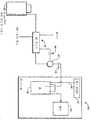
도 1을 참조로, 정제 장치의 한 실시양태가 개략적으로 도시되어 있고 무용량 구역이 전체 정제 흐름 채널을 포함한다. 일반적으로 (10)으로 표시되는 정수기는 도시되지 않은 하우징(12) 및 각각 내벽(16a) 및 외벽(16b)이 있으며 교환가능한 음이온을 갖는 음이온 교환막(16)으로부터 이격된, 각각 내벽(14a) 및 외벽(14b)이 있으며 교환가능한 양이온을 갖는 양이온 교환막(14)을 포함한다. 내벽(14a) 및 (16a)은 이격되어 있으며 일반적으로는 서로 평행하고 이들 사이에 정제 흐름 채널(18)을 형성한다. 막(14) 및 (16)은 다량의 액체 흐름은 방지하지만 상응하는 교환가능한 이온과 동일한 전하의 이온을 통과시킨다.With reference to FIG. 1, one embodiment of a purification apparatus is schematically illustrated and the capacityless zone comprises the entire purification flow channel. The water purifier, generally indicated at 10, has an
정수기(10)는 또한 막(14)의 외벽(14b)면에 양이온 챔버(20) 및 막(16)의 외벽(16b)면에 음이온 교환 챔버(22)를 포함한다. 흐름-관통성 양이온 교환 매질(24)은 챔버(20)내에 배치되고 흐름-관통성 음이온 교환 매질(28)은 챔버(22)에 배치된다. 캐소드(30) 및 애노드(32)는 이격되어 있고 흐름 채널(20) 및 (22) 각각과 전기적으로 연결된다. 조작에서, 캐소드와 애노드를 전원(도시되지 않음)에 연결시켜, 음이온 교환 매질(24), 막(14), 정제 흐름 채널(18), 막(16) 및 음이온 교환 매질(28)을 통해 그리고 이들 사이에 직류가 흐르게 한다. 예시된 바와 같이, 캐소드(30) 및 애노드(32)는 막(14) 및 (16)과 외부 매질(24) 및 (28) 각각에 평행하게 배치된다. 캐소드(30) 및 외벽(14b)은 흐름 채널(20)을 형성하는 반면 애노드(32) 및 외벽(16b)은 흐름 채널(22)을 형성한다. 예시된 바와 같이, 이온 오염물질을 포함하는 정제될 물은 공급원(도시되지 않음)으로부터 화살표(32) 방향으로 흘러 정제 흐름 채널(18)을 통해 정수기(10) 출구로 배출된다. 하나 이상의 공급원(도시되지 않음)으로부터의 물은 바람직하게는 흐름 채널(20) 및 (22)를 통해 화살표(32)의 방향으로 흐르는 정제시킬 물과 반대방향인 화살표(34) 및 (36) 방향으로 흘러, 오염물질 이온으로부터 흐름 채널에 형성된 염기 및 산 각각을 소제한다.The
정수기(10)의 구조(예: 막 및 일반적인 배치)는 전체 내용이 본원에 참조 문헌으로 인용된 미국 특허 제4,999,098호 및 제5,352,360호에 기술된 유형의 억제기에 대하여 기재된 일반적인 유형의 것일 수 있다. 예시된 바와 같이, 막은 평평하거나 동심형 관과 같은 또 다른 배치일 수 있다. 하나의 유의적인 차이는 막(14) 및 (16)이 반대 전하인 반면, 당해 특허에서는 샌드위치 억제기 실시양태의 평행막이 동일 전하라는 점이다. 이는 도 1의 장치로부터의 억제기가 상이한 기능을 한다는 것을 설명한다. 구체적으로, 본 발명에서, 전위가 캐소드(30) 및 애노드(32) 사이를 지날 때, 양이온 오염물질, 예를 들면 나트륨은 양이온 막(14)을 횡단하여 캐소드(30)로 유인되는 반면, 음이온 오염물질은 음이온 교환막(16)을 횡단하여 애노드(32) 방향으로 유인된다. 이러한 방법으로, 양이온 및 음이온 불순물이 정제 흐름 채널(18)에서 물 스트림으로부터 제거된다.The structure (eg, membrane and general arrangement) of the
본 발명에서, 흐름-관통성 이온 교환 매질(24) 및 (28)은 채널(20) 및 (22)에 배치되는 반면, 흐름-관통성 음이온 교환 매질이 실질적으로 함유되지 않거나, 매질(24) 및 (28)에 비해 낮은 이온 교환 용량, 즉 매질 (24) 및 (28)의 25% 이하, 바람직하게는 1% 미만의 이온 교환 용량을 갖는 흐름-관통성 이온 교환 매질을 함유하는 정제 흐름 채널(18)의 길이 내에 있으며 이러한 채널 길이와 동일공간에 있는 구역은 유지시킨다. 이온 교환 매질(24) 및 (28)은 (1) 막과 동일한 이온 교환 형태로 주로 존재하거나, (2) 반대 전하로 주로 존재하거나, 하기에 기술하는 바와 같이, (3) 교환가능한 음이온 또는 양이온의 혼합물일 수 있는 교환가능한 이온을 가질 수 있다. 이들 배치 각각에서, 장치는, 정제 흐름 채널에서의 흐름-관통성 매질의 낮거나 부재하는 이온 교환 용량으로 인해 전류 효율적이다.In the present invention, the flow-through
도 1에 예시된 바와 같이, 정제 흐름 채널(18)에는 흐름-관통성 매질, 이온 교환 등이 전혀 존재하지 않으므로, 구역은 전체 정제 흐름 채널을 포함한다. 그러나, 예를 들어 상기 제'098호 또는 제'360호 미국 특허에 예시된 바와 같이 스크린과 같은 흐름 채널(18)에 중성 흐름-관통성 물질(예; 폴리에틸렌 또는 폴리프로필렌 재질의 것)을 넣는 것이 유리하다. 스크린의 한 이점은 이것이 스페이서로서 역할하여 서로 떨어져 있는 유연성 막(14) 및 (16)이 일반적으로 평행 배치로 유지되도록 한다는데 있다. 다른 이점은 물 스트림의 혼합을 증가시켜 오염물질 이온이 막으로 이송되는 것을 촉진시키고 교환 동력학을 개선시켜 오염물질 이온의 제거를 증진시키는 것을 포함한다. 대안적으로, 중성 입자는 채널(18)내의 흐름-관통성 베드에 충전되거나, 흐름-관통성 다공성 단일체(monolith)가 사용될 수 있다.As illustrated in FIG. 1, there is no flow-through medium, ion exchange, or the like, in the
흐름-관통성 음이온 교환 매질(24) 및 (28)의 한 형태는 이온 교환 스크린을 포함하는데, 이는 막의 사실상 전체 길이를 따라 배치된 연속적인 회선상(convoluted)의 흐름-관통성 경로를 제공하며 상기에 기재한 스페이서로서의 역할을 한다. 이는 난류를 일으켜 혼합 효율을 증가시키고 막(14) 및 (16)으로부터 음이온이 캐소드(30) 및 애노드(32)로 각각 이동하는 것을 증가시킨다. 이온 교환 스크린의 이점은 이들이 막과 상응하는 전극 사이의 거리를 가교하여 상기 제'098호 또는 제'360호 미국 특허에 기재된 바와 같이 그 장소에 유지시키는 것이 용이하게 된다는 점이다. 장치의 전기 저항 및 소모는, 막과 전극 사이의 전도성 가교로서의 이온 교환 스크린의 존재로 인해 감소된다. 이온 교환 매질(24) 및 (28)의 존재는 전해질 기체의 존재 하에서의 전류의 균일한 이동을 가능하게 한다. 이온 교환 매질의 부재는 전해질 기체의 존재로 인한 전류 중의 편차를 초래하고, 그 결과 물 스트림의 불량한 탈이온화가 유발된다.One form of flow-through
이러한 스크린 및 당해 스크린을 이온 교환 형태로 작용화시키는 적합한 기술은 익히 공지되어 있고 상기 특허들에 기술되어 있다. 필요에 따라, 다른 형태의 흐름-관통성 이온 교환 매질 또는 충전재가 사용될 수 있다. 예를 들면, 이온 교환 입자는, 예를 들어 이온 교환 수지 입자보다 기공이 작은 것을 사용하여 각각의 말단에 다공성 중합체 지지체를 사용함으로써 장치내에 이온 교환 입자를 유지시키는 구조물을 포함하는 채널 (20) 및 (22)에 충전될 수 있는데, 이는 예를 들어 상기 제'098호 또는 제'360호 미국 특허에 기재되어 있다. 또는, 흐름-관통성 기공이 있는 이온 교환 물질의 단일체를 또한 사용할 수 있다.Such screens and suitable techniques for functionalizing such screens in ion exchange form are well known and described in the above patents. If desired, other forms of flow-through ion exchange media or fillers may be used. For example, the ion exchange particles may comprise a
한 실시양태에서, 흐름-관통성 이온 교환 매질 (24) 및 (28)은 인접한 막(14) 및 (16) 각각과 동일한 극성의 교환가능한 이온을 갖는다. 예시된 바와 같이, 양이온 교환 매질(24)은 양이온 형태로 주로(예: 30% 이상) 존재하는 반면, 음이온 교환 매질(28)은 음이온 교환 형태로 주로(예: 30% 이상) 존재할 것이다. 이온 교환 매질의 적합한 용량은 0.2 내지 2 meq/g이다. 상기에 설명한 바와 같이, 바람직한 실시양태에서, 정제 흐름 채널에는 흐름-관통성 이온 교환 용량이 존재하지 않는다.In one embodiment, the flow-through
전형적인 조작 조건은 다음과 같다. 장치는 바람직하게는 정전압 조건하에 전력을 공급받을 것이다. 전형적인 최소 조작 전압은 장치의 치수에 의존적이다. 음이온 또는 양이온 채널과 함께 정제 채널용으로 바람직한 조작 전압은 2 V 내지 24 V 또는 그 이상이다. 전류는 오염물질 수준에 따라 자가 조정될 것이다. 정전류의 적용은 흐름-관통성 이온 교환 매질이 없는 정제 채널을 사용하는 실시양태에 대해서는 실용적이지 않은데, 그 이유는 오염물질 농도를 사전에 알아야 하기 때문이다. 정제 채널이 약간의 용량을 갖는 실시양태에서는 정전류의 적용이 가능할 것이다. 그러나 적용된 전류는 소정의 물 스트림을 탈이온화하기 위해 필요한 전류를 초과하여야 한다. 전류가 많이 흐를수록 발열량 및 기체 형성이 많아지므로 정전압은 조작의 가장 바람직한 수단이다.Typical operating conditions are as follows. The device will preferably be powered under constant voltage conditions. Typical minimum operating voltages depend on the dimensions of the device. Preferred operating voltages for purification channels with anionic or cationic channels are 2 V to 24 V or more. The current will self-adjust according to the pollutant level. The application of constant current is not practical for embodiments that use purification channels without flow-through ion exchange media, because contaminant concentrations must be known in advance. In embodiments where the purification channel has some capacity, application of constant current would be possible. However, the applied current must exceed the current required to deionize a given water stream. Constant current is the most preferable means of operation because more current flows and more calorific value and gas formation.
크로마토그래피 적용에 사용할 경우 본 발명의 장치는 바람직하게는 유량 범위 0 내지 3 ml/분 또는 0 내지 0.18 LPH, 보다 바람직하게는 0 내지 2 ml/분 또는 0 내지 0.12 LPH에서 조작될 것이다. 실험실 적용을 위한 본 발명의 장치는 바람직하게는 0.1 LPH에서 20 LPH로 조작될 것이다. 장치는 끊임없이 가동될 수 있거나 필요에 따라 사용될 수 있다.When used in chromatographic applications the apparatus of the invention will preferably be operated in a flow rate range of 0 to 3 ml / min or 0 to 0.18 LPH, more preferably 0 to 2 ml / min or 0 to 0.12 LPH. The apparatus of the invention for laboratory applications will preferably be operated from 0.1 LPH to 20 LPH. The device can be operated continuously or can be used as needed.
상기 시스템의 사용에서, 정정압 전원을 사용하여 나트륨과 같은 양이온이 캐소드 쪽으로 유인되도록 하는 반면, 클로라이드와 같은 음이온은 애노드 쪽으로 유인되도록 할 수 있다. 그 결과, 전기장에서의 이온의 이동으로 정제 흐름 채널(18)의 하부로부터 나오는 탈이온수 스트림을 정제하게 된다. 장치는 수성 물 스트림을 탈이온화하는데 필요한 전류만을 유인할 것이다. 이는 정제 흐름 채널에 실질적인 기타 전류 수반 성분, 예를 들어 흐름-관통성 이온 교환 매질이 존재하지 않기 때문이다. 따라서, 오염물질 이온에 의해 전해지는 전류의 거의 모두가 각각의 막을 통해 통과한다.In the use of such a system, a positive pressure power source can be used to attract cations such as sodium to the cathode, while anions such as chloride can be attracted to the anode. As a result, the movement of ions in the electric field will purify the deionized water stream coming from the bottom of the
음이온 교환 매질 및 인접한 막에 대하여 동일한 극성을 사용함으로써, 제거된 이온이 이들이 상응하는 전극에 이르기 전에 트랩핑되어 산 및 염기가 각각의 흐름 채널에 형성된다. 예를 들면, 양이온 교환막(14) 및 양이온 교환 물질(24)에 대하여, 오염물질로서 나트륨을 사용하면, 나트륨 이온이 캐소드(30) 방향으로 전기이동(electomigration)함으로써 막(14)을 횡단하여 이동한다. 유사하게, 음이온 교환막(16) 및 음이온 교환 물질(28)에 대하여, 오염물질로서 클로라이드를 사용하면, 클로라이드 이온이 애노드(32) 방향으로 전기이동함으로써 막(16)을 횡단하여 이동한다. (부반응 이외의) 반응은 다음과 같이 기재할 수 있는데, 캐소드로 이동한 각각의 나트륨에 대하여 하나의 클로라이드 이온이 애노드로 이동하여 전기적 순환을 완결하게 된다. 캐소드로 이동한 나트륨(또는 다른 양이온)은 (캐소드에서 전기분해 물 분해 반응으로부터 생성된) 수산화 이온과 반응하여 캐소드에서 수산화나트륨(양이온 수산화물)을 형성시키고, 유사하게 동시에 애노드로 이동한 클로라이드(또는 다른 음이온)는 (애노드에서 전기분해 물 분해 반응으로부터 생성된) 하이드로늄 이온을 취하여 애노드에서 염산(음이온)을 형성시킨다. 전극에서 반응하는 각각의 나트륨(또는 양이온)에 대하여 하나의 나트륨 또는 양이온이 양이온 교환 물질(24)로 들어간다. 유사하게, 애노드에서 반응하는 각각의 클로라이드(또는 음이온)에 대하여 하나의 클로라이드 또는 음이온이 음이온 교환 물질(28)로 들어간다.By using the same polarity for the anion exchange medium and the adjacent membrane, the removed ions are trapped before they reach the corresponding electrode so that acid and base are formed in each flow channel. For example, for the
캐소드에서At the cathode
2H2O + 2e- -----> 2OH- + H22H 2 O + 2e - -----> 2OH - + H 2
애노드에서On the anode
H2O -----> 2H+ + 1/2O2+ 2e-H 2 O -----> 2H + + 1 / 2O 2 + 2e -
다른 실시양태에서, 이온 교환 매질(24) 및 (28)의 극성은 역전된다. 여기서, 음이온 교환 매질(24)은 주로 음이온 교환 형태로 교환가능한 이온을 갖는다. 유사하게, 음이온 교환 매질(28)은 막(16)에 대해 반대 극성, 즉, 양이온 교환 형태로 교환가능한 이온을 갖는다. 이러한 배치에서, 오염물질 이온은 막(14b 또는 16b)과 이온 교환 매질(24 또는 28) 사이의 계면에서 염기 및 산 형태로 전환된다. 제거된 이온은 전극 챔버(또는 이온 교환 매질 (24) 또는 (28))에 유지되지 않기 때문에, 장치는 이러한 배치에서 더욱 신속히 평형화된다. 전류가 오염물질 이온에 의해 단독으로 이동한다.In other embodiments, the polarities of
예를 들면, 양이온 교환막(14) 및 음이온 교환 물질(24)에 대하여 오염물질로서 나트륨을 사용하면, 나트륨 이온이 캐소드(30) 방향으로 전기이동함으로써 막(14)을 횡단하여 이동한다. 유사하게, 음이온 교환막(16) 및 양이온 교환 물질(28)에 대하여 오염물질로서 클로라이드를 사용하면, 클로라이드 이온이 애노드(32) 방향으로 전기이동함으로써 막(16)을 횡단하여 이동한다. (부반응 이외의) 반응은 다음과 같이 기재할 수 있는데, 캐소드로 이동한 각각의 나트륨에 대하여 하나의 클로라이드 이온이 애노드로 이동하여 전기적 순환을 완결하게 된다. 전기분해 물 분해 반응은 캐소드에서 수산화 이온을 생성시키고 애노드에서 하이드로늄 이온을 생성시킨다. 음이온 교환 물질(24)은 전기분해로 생성된 수산화물이 막(14b)의 표면까지 이송될 수 있게 한다. (14b) 및 (24) 사이의 계면에서, 제거된 나트륨(양이온)은 수산화 이온과 반응하여 수산화나트륨(양이온 수산화물)을 형성한다. 유사하게, 양이온 교환 물질(28)은 전기분해로 생성된 하이드로늄 이온이 막(16b)의 표면까지 이송될 수 있게 한다. (16b)와 (28) 사이의 계면에서, 제거된 클로라이드(음이온)는 하이드로늄 이온과 반응하여 염산(음이온 산)을 형성한다. 계면에서 반응하는 각각의 나트륨(또는 양이온)에 대하여 하나의 나트륨 또는 양이온이 양이온 교환 막(14)으로 들어가고 하나의 수산화 이온이 음이온 교환 매질(24)로 들어간다. 유사하게, 계면에서 반응하는 각각의 클로라이드(또는 음이온)에 대하여 하나의 클로라이드 또는 음이온이 음이온 교환 막(16)으로 들어가고 하나의 하이드로늄이 양이온 교환 매질(28)로 들어간다.For example, when sodium is used as a contaminant for the
캐소드에서At the cathode
2H2O + 2e- -----> 2OH- + H22H 2 O + 2e - -----> 2OH - + H 2
애노드에서On the anode
H2O -----> 2H+ + 1/2O2+ 2e-H 2 O -----> 2H + + 1 / 2O 2 + 2e -
또다른 실시양태에서, 음이온 교환 매질(24) 및 (28)은 교환가능한 양이온과 음이온의 혼합물을 함유하는 매질을 포함할 수 있다. 스크린을 사용할 경우, 스크린은 양이온 및 음이온 교환 용량 또는 작용성 둘 모두를 가질 수 있다. 대안적으로, 각각의 유형의 하나의 스크린을 사용할 수 있다. 충전층 음이온 교환 매질에서, 충전재는 음이온, 양이온 교환 입자의 혼합물일 수 있다. 이러한 형태의 음이온 교환 매질의 이점은 다음과 같다. 전기분해로 생성된 이온(하이드로늄 및 수산화물)은 이동 경로를 갖는 반면, 제거된 오염물질 이온은 채널(20) 및 (22)에서 전극으로 전기이동한다. 앞서 논의한 실시양태에서, 제거된 오염물질 이온이 이동하거나 전기분해 이온이 채널 (20) 및 (22)에서 이동할 수 있는데 둘 다의 경우는 아니다. 따라서 산 및 염기의 형성은 계면 뿐만 아니라 이온이 전기 분해로 생성된 하이드로늄 또는 수산화 이온의 부근에 있는 임의의 장소에서 일어날 수 있다. 따라서 이러한 실시양태의 장치는 저항을 감소시킬 것이고 탈이온화 작용을 더 효율적으로 작동시킬 것으로 예상된다.In another embodiment, the
100% 패러데이 효율로 소정 농도의 오염물질을 탈이온화 하는데 필요한 전류는 다음 식으로부터 산출될 수 있다.The current required to deionize a given concentration of contaminants at 100% Faraday efficiency can be calculated from the following equation.
I = FCV/60I = FCV / 60
상기 식에서,Where
I는 전류(mA)이고,I is the current in mA,
F는 패러데이 상수(쿨롱/당량)이고,F is a Faraday constant (coulomb / equivalent),
C는 오염물질의 농도(M)이고,C is the concentration of the contaminant (M),
V는 유량(ml/분)이다.V is the flow rate (ml / min).
100% 패러데이 효율로 2 mM의 NaCl를 함유하는 스트림을 탈이온화하는데 필요한 전류는 약 3.2 mA로 산출될 수 있다.The current required to deionize a stream containing 2 mM NaCl at 100% Faraday efficiency can be calculated as about 3.2 mA.
도 1의 배치에서, 중성 스크린을 희석 또는 정제 채널에 사용할 경우, 많은 양의 전류가 스트림 중의 이온 오염물질에 의해 전해져서 장치는 약 100%에 가까운 패러데이 전류 효율을 나타낸다. 중성 스크린이 저용량(예를 들어, 외부 흐름 채널 25% 미만)으로 대체될 경우, 음이온 및 양이온 교환 용량으로 약간 작용화된 스크린에서 다량의 전류가 여전히 오염물질에 의해 전해지고 스크린을 통과하는 과량의 H+ 또는 OH-의 이동으로 인해 물을 형성하는데 적은 백분율의 전류가 소모된다.In the arrangement of FIG. 1, when a neutral screen is used in the dilution or purification channel, a large amount of current is carried by the ionic contaminants in the stream such that the device exhibits a near-day Faraday current efficiency. If the neutral screen is replaced by a low volume (e.g., less than 25% of the external flow channel), in the screen slightly functionalized with anion and cation exchange capacity, a large amount of current is still carried by contaminants and excess H passing through the screen. Due to the movement of+ or OH- a small percentage of current is consumed to form water.
본 발명에 따른 전형적인 전류 효율은 80 내지 100%, 바람직하게는 95% 이상만큼 높을 수 있다.Typical current efficiencies according to the invention can be as high as 80 to 100%, preferably at least 95%.
조작에서, 도 1의 정수기를 사용하여 다음 방법에 의해 물 스트림으로부터 오염물질을 제거함으로써 당해 물 스트림을 정제할 수 있다. 이온 오염물질을 포함하는 물 스트림은, 정제 흐름 채널의 한면에 배치된 교환가능한 양이온을 갖는 양이온 교환막(14) 및 정제 흐름 채널의 다른 한면을 따라 배치된 교환가능한 음이온을 갖는 음이온 교환막(16)에 의해 형성된 정제 흐름 채널(18)을 따라 흐른다. 전형적으로, 물 스트림은 강산이나 강염기가 아니다. 막은 다량의 액체 흐름은 방지하지만 상응하는 교환가능한 이온과 동일한 전하를 갖는 이온은 통과시킨다. 수성 스트림, 전형적으로는 산 또는 염기가 아닌 수돗물이 정제 흐름 채널로부터 각각의 막의 반대면에 있는 음이온 교환 매질(24) 및 (28)를 통해 흐른다. 전위를 각각의 흐름 채널과 전기적으로 연결된 캐소드(30) 및 애노드(32) 사이에 적용시킨다. 정제 흐름 채널은, 흐름-관통성 음이온 교환 매질을 함유하지 않거나, 외부 플로우 교환 매질에 대해 5% 이하의 이온 교환 용량을 갖는 흐름-관통성 음이온 교환 매질을 갖는다. 양이온 불순물은 채널(18)로부터 막(14)을 통해 캐소드(30) 방향으로 흘러 이온 교환 매질(24)로 들어간다. 선행 반응은 매질의 전하에 따라서 음이온 교환 매질(24)에서 일어난다. 전형적으로, 나트륨과 같은 양이온이 수산화나트륨과 같은 염기로 전환되어, 채널(20)을 통해 흐르는 물 스트림에서 시스템으로부터 흘러나와, 바람직하게는 정제될 물과 반대 방향으로 흐르는 스트림에서 이온을 농축시킨다. 유사하게, 음이온은 애노드(32) 방향으로 음이온 교환막(16)을 거쳐 유인되고, 상기한 반응이 일어난다. 전형적으로 클로라이드와 같은 음이온은, HCl과 같은 산 형태로 전환되어, 바람직하게는 정제 흐름 채널(18)을 통해 흐르는 물과 반대 방향으로, 흐름 채널(22)을 통해 흐르는 물 스트림에서 시스템으로부터 흘러나온다.In operation, the water stream can be purified by using the water purifier of FIG. 1 to remove contaminants from the water stream by the following method. A water stream comprising ionic contaminants is added to a
본 발명의 한 양태는, 그 사이에서 제2 정제 흐름 채널을 형성하는 제2 양이온 및 음이온 교환막; 제2 양이온 또는 음이온 흐름 채널을 각각 형성하는 제2 양이온 또는 음이온 흐름 챔버; 제2 양이온 또는 음이온 흐름 채널에 배치된 흐름-관통성 제2 이온 교환 수지; 및 제1 및 제2 이온 교환 매질에 대해 25% 초과의 이온 교환 용량을 갖는 흐름-관통성 이온 교환 매질을 함유하지 않는 제2 정제 흐름 채널의 길이 내에 있고 이러한 채널 길이와 동일공간에 있는 구역을 포함하는 정제 장치이다. 도시되지는 않았지만 시스템은 상기 기재한 유형의 다중 병렬 흐름 채널로 이루어질 수 있다. 이 경우, 단일 전원이, 애노드 및 캐소드가 오염물질 이온을 수용하는 최외부 이온 교환 매질 함유 흐름 채널과 연통되는 한, 계속하여 사용될 수 있다. 예를 들면, 미국 특허 제2,794,777호의 배치에서는 교호막을 사용할 수 있는데, 여기에서 기재된 유형의 음이온 및 양이온 교환막이 교대되어 있다. 정제될 물 스트림은 이온 수용 채널에 의해 측면에 위치한 교대 흐름 채널을 통해 평행한 스트림에서, 사실상 이온 교환 매질을 함유하지 않은 구역을 포함하는 정제 흐름 채널을 통해 흐른다. 각각 정제 흐름 채널 측면에 위치한 흐름 채널은 상기 기재한 바와 같이 이온 교환 매질을 포함한다. 전압을 가할 경우, 오염물질은 반대 극성의 교환가능한 이온이 있는 막을 거쳐 앞서 기재한 바와 같은 측면에 위치한 흐름 채널로 흘러들어간다. 이와 같은 방식으로, 두 개 이상의 평행 물 스트림이 단일 전원을 사용한 정제 흐름 채널에서 정제될 수 있다. 대안의 실시양태에서, 도시되지는 않았지만, 도 1의 다중 장치가 사용될 수 있다.One aspect of the invention provides a second cation and anion exchange membrane that forms a second purification flow channel therebetween; A second cation or anion flow chamber each forming a second cation or anion flow channel; A flow-through second ion exchange resin disposed in the second cation or anion flow channel; And a zone within the length of the second purification flow channel that does not contain a flow-through ion exchange medium having an ion exchange capacity of greater than 25% for the first and second ion exchange media and co-spaced with the channel length. It is a purification device that includes. Although not shown, the system may consist of multiple parallel flow channels of the type described above. In this case, a single power source can continue to be used as long as the anode and cathode are in communication with the outermost ion exchange medium containing flow channel containing the pollutant ions. For example, alternating membranes can be used in the arrangement of US Pat. No. 2,794,777, where anion and cation exchange membranes of the type described herein are alternated. The water stream to be purified flows in a parallel stream through alternating flow channels flanked by ion receiving channels and through a purification flow channel comprising a zone that is substantially free of ion exchange media. Each flow channel located on the side of the purification flow channel comprises an ion exchange medium as described above. Upon application of voltage, contaminants flow through membranes with exchangeable ions of opposite polarity into flow channels located on the sides as described above. In this way, two or more parallel water streams can be purified in a purification flow channel using a single power source. In an alternative embodiment, although not shown, multiple devices of FIG. 1 can be used.
정제된 이온수는 이온 크로마토그래피 시스템 또는 자가 샘플채취기와 같은 고도로 정제된 탈이온수를 요구하는 임의의 분석 시스템에 온라인으로 공급될 수 있다. 예를 들면, 크로마토그래피 시스템용으로, 정제된 탈이온수를 전개 시약 또는 전해질과 혼합하여, 크로마토그래피 컬럼을 통해 샘플을 운반하는 용리액을 형성시킬 수 있다.Purified ionized water can be supplied online to any analytical system that requires highly purified deionized water, such as ion chromatography systems or self-samplers. For example, for chromatographic systems, purified deionized water may be mixed with the developing reagent or electrolyte to form an eluent that carries the sample through the chromatography column.
도 2 내지 6은 본 발명에 따른 정제수 전달 시스템의 상이한 실시양태를 예시한 것이다. 이들 실시양태에서 유사 부분은 유사 번호로 명명될 것이다.2-6 illustrate different embodiments of purified water delivery systems according to the present invention. In these embodiments, similar parts will be named by like numbers.
도 2에 도시된 본 발명의 하나의 실시양태에서, 정수기(10)는 일반적으로 (40)으로 표시되는 이온 크로마토그래피(IC) 시스템으로 정제된 탈이온수를 온라인으로 공급하도록 배치된다. 이 실시양태에서, 세방향 T자 연결관 또는 적합한 배압 제한 배관 (44) 및 (46)과 함께 액체 스트림 스플리터(42)는 정제수 스트림을 정수기(10)로부터 2개의 스트림으로 분할시킨다. 제1 스트림은, 도 2에 도시된 바와 같이, 관(46)과 같은 제1 도관을 통해 크로마토그래피 시스템 저장소(48)로 우회되고, 이는 다시 IC 펌프(50)로 유동적으로 연결된다. 저장소(48)의 부피는 적합하게는 1 내지 4 리터(예: 다이오넥스 코포레이션에서 시판하는 이온 크로마토그래피 시스템 저장소의 부피)이다. 그러나, 제1 스트림은 본 발명의 범주내에서 IC 펌프(50)에 직접 연결되도록 제공될 수 있음을 이해하여야 할 것이다. 제2 스트림은 관(44)과 같은 제2 도관을 통해 정수기 유닛(10)으로 다시 우회되어 오염물질을 제거하고 전기분해 물 분해 반응을 위한 물을 제공한다. 본 발명의 목적을 위해, 용어 "도관"은 파이프 또는 관 뿐만 아니라, 일반적으로 액체가 운반되는 채널, 예를 들면 유체 경로를 의미한다. 두 개 스트림의 바람직한 유량 비는 약 1:1 내지 1:10의 범위일 수 있는데, 이 경우 유량의 대부분은 IC 저장소(48)로 흐른다. 이 실시양태에서, 전기탈이온화기(10)의 음이온 또는 양이온 채널(또는 전극 채널)로 공급되는 물 스트림은 정제된 스트림이다.In one embodiment of the invention shown in FIG. 2, the
가압 공급원 저장소(52)는 오염수를 정수기(10)로 공급한다. 바람직하게는, 기체압 또는 펌프를 설치하여, 정제시킬 물을 공급원 저장소(52)로부터 정수기(10) 및 IC 시스템(40)으로 분배한다. 크로마토그래피 적용을 위한 저장소의 바람직한 압력은 정수기의 배압 및 제한기에 의존적이다. 크로마토그래피 저장소(48)에 가해지는 압력은 일반적으로 5 psi 내지 30 psi이다.Pressurized source reservoir 52 supplies contaminated water to
조작 및 사용에서, 가압 공급원 저장소(52)는 유입되는 오염수 스트림을 압력 "P"에서 공급하는데, 유입되는 상기 스트림은 전기탈이온화기(10)를 통과해서 IC 저장소(48)로 IC 저장소 압력이 "P"가 될 때까지 흘러들어간다. 이러한 조건을 충족시키고/거나 용기가 가득찬 경우, 과량의 흐름이 정제 장치(10)의 음이온 및 양이온 챔버(20 및 22)로 우회된다. 이러한 셋업은 크로마토그래피 시스템(40)으로 흐른다거나 오염물질이 크로마토그래피 저장소(48)로 우회되는 것과 관련된 어떠한 문제 없이 계속해서 작동될 수 있다. 크로마토그래피 펌프(50)가 IC 저장소(48)로부터 물을 펌핑하기 시작할 때, IC 저장소(48)내의 압력이 떨어지고 이것이 "P"보다 낮을 경우는 공급원 저장소(52)로부터 유입되는 물 스트림이 다시 IC 저장소(48)를 채우기 시작한다. 이러한 배치에서, IC 저장소는 계속 채워지고/거나 탈이온수는 IC 펌프(50)에 제공된다. 이렇게 계속 충전되는 방법은 어떠한 유량 또는 수준 센서를 사용하지 않고도 달성된다.In operation and use, pressurized source reservoir 52 feeds the incoming contaminant stream at pressure "P", which enters the
도 3에 제시된 실시양태에서, 기체압 공급원(54)은 정압 "Q"를 크로마토그래피 저장소(48)에 공급한다. 이 실시양태에서, 기체 라인(56)은 기체압 공급원(54)을 IC 저장소(48)에 조작가능하게 연결시키고, 바람직하게는 체크 밸브(58)를 포함하여 기체 라인(56)으로의 물의 역류를 방지한다. 기체압 "Q"가 "P"보다 낮을 경우, IC 저장소(48)를 저장소의 압력이 "P"가 될 때까지 채운다. IC 펌프(50)가 작동하는 동안, IC 저장소 압력은 "Q" 내지 "P" 범위의 압력으로 유지되고, 압력이 "P" 미만으로 떨어질 경우 가압 공급원 저장소(52)로부터의 새로이 탈이온화된 스트림으로 다시 자동적으로 보충된다. 이러한 배치는 탈이온수의 자가 유지성 공급원을 IC 시스템(40)에 공급하여 추가로 센서를 사용하지 않고도 유지된다.In the embodiment shown in FIG. 3,
상기에서 주지한 바와 같이, IC 저장소는 전적으로 우회될 수 있고 정제된 물 스트림은 IC 펌프에 직접 접속될 수 있다. 이러한 배치에서, IC 펌프(50)가 작동하는 경우, IC 펌프의 압력은 항상 "P" 미만일 것이고 물 스트림은 정수기(10)를 통해 IC 펌프(50)로 계속 공급된다. IC 펌프(50)가 작동하는 동안, 과잉 흐름의 물 스트림은, 있다손 치더라도, 정수기(10)의 음이온 및 양이온 채널(22 및 20)로 우회된다. IC 펌프(50)가 중단될 경우, 관(46)을 통하는 압력을 포함하는 라인 압력은 "P"에 이르고, 스트림의 전체 흐름이 정수기(10)의 음이온 및 양이온 채널(22 및 20)로 우회된다. 음이온 및 양이온 채널로의 이러한 과잉 흐름은 전기탈이온화기의 성능에 불리한 영향을 전혀 미치지 않으며 정수 장치는 항상 재생된다.As noted above, the IC reservoir can be bypassed entirely and the purified water stream can be connected directly to the IC pump. In this arrangement, when the
도 4에 나타낸 다른 실시양태에서, 정제되어야 할 유입 물 스트림은 공정 스트림, 예를 들면 저장소 대신에 역삼투압(RO) 스트림(60)으로부터 펌프된다. RO 스트림을 위한 압력 범위는 전형적으로는 약 30 내지 60 psi이다. 다른 압력도 사용될 수 있음을 이해하여야 한다.In another embodiment shown in FIG. 4, the influent water stream to be purified is pumped from a reverse osmosis (RO)
도 5에 나타낸 다른 실시양태에서, 세방향 T자 연결관(42)이 탈이온화기(10)의 전면 말단부에 제공된다. T자 연결관(42)은 적합한 배압 제한 배관 (44), (46) 및 (62)와 함께 RO 공급 스트림(60)으로부터 정제수 스트림을 2개의 스트림으로 분할시킨다. 제1 스트림은 관(62)과 같은 도관을 통해 정수기(10)의 정제 흐름 채널(18)로 우회되고, 이는 다시 크로마토그래피 시스템 저장소(48) 및 IC 펌프(50)로 유동적으로 연결된다. 제2 스트림은 관(44)과 같은 제2 도관을 통해 정수기 유닛(10)의 양이온 및 음이온 챔버(20 및 22)로 우회되어 오염물질을 제거하고 도 1과 관련하여 설명된 전기분해 물 분해 반응을 위한 물을 제공한다. 이 실시양태에서, 전극 채널, 즉, 전기탈이온화기(10)의 음이온 또는 양이온 채널(20 또는 22)은 오염물질 이온을 갖는 비정제수의 스트림에 공급된다.In another embodiment, shown in FIG. 5, a three-way T-shaped
정제수를 공급하기 위한 상기한 바와 같은 배치는 본 발명에 따른 통상적인 정수기와 함께 사용될 수 있다. 상기 배치를 사용하여 다른 유형의 정수기를 분석 시스템에 직접 접속시킬 수 있다. 예를 들면, 도 6에 나타낸 실시양태는 적합한 제한 배관 (46) 및 (64)와 함께 재순환용의 과량의 정제수를 우회시키는 세방향 T자 연결관(42)을 포함한다. 특히, 세방향 T자 연결관(42)은 정수기(10)로부터 과량의 정제수를 정제되어지는 RO 공급원 스트림(60)으로 우회시킨다. 우회 펌프(66)는 과량의 물을 RO 공급원 스트림으로 다시 운반하기 위해 제공된다. 대안적으로, 우회된 과량의 물이 공급원 저장소, 예를 들면 저장소(52), 배출 포트, 폐기물 포트, 또는 기타 적합한 수용기 또는 통로로 다시 운반될 수 있다. 우회 펌프(66)는, 우회된 과량의 물이 공급원 스트림보다 압력이 낮은 수용기 또는 통로로 운반될 경우에는, 제공될 필요가 없음을 이해하여야 할 것이다.The arrangement as described above for supplying purified water can be used with conventional water purifiers according to the invention. This arrangement can be used to connect other types of water purifiers directly to the analysis system. For example, the embodiment shown in FIG. 6 includes a three-way T-shaped
본 발명의 장치의 이점은 다음과 같은 것들을 포함한다. 화학적 재생제를 필요로 하지 않으며 전기분해적으로 끊임없이 작동될 수 있고 휴지 시간(down time)을 포함하지 않는다. 정전압 조건하에서 작동될 경우 탈이온화에 필요한 전류만이 필요하다. 유량 변화에 의해 영향받지 않고 유입되는 오염물질의 농도에 대해 전류가 자가 조정된다는 점에서 단일 전압 세팅을 사용하여 작동될 수 있다. 따라서, 어떠한 사용자의 개입도 요구되지 않는다. 크로마토그래피 적용을 위한 온라인 정수기로서 작동될 수 있다.Advantages of the device of the present invention include the following. It does not require chemical regenerants and can be operated electrolytically constantly and does not include down time. When operating under constant voltage conditions, only the current required for deionization is required. It can be operated using a single voltage setting in that the current is self-adjusting for the concentration of incoming contaminants without being affected by flow rate changes. Thus, no user intervention is required. It can be operated as an on-line water purifier for chromatographic applications.
본 발명의 추가의 세부사항은 하기 비제한적 실시예로 예시된다.Further details of the invention are illustrated by the following non-limiting examples.
실시예 1Example 1
스크린 및 막은 방사선 그래프팅된 물질들이고 미국 특허 제4,999,098호 및 제5,352,360호에 기재된 바에 따라 개스켓과 함께 제조되었다. 다이오넥스 코포레이션으로부터 시판되는 ASRS 억제기 하드웨어를 그대로 사용하였다. 어셈블링 포멧은 도 1에 개략적으로 나타낸 것에 따랐다. 장치를 12 V에서 Hewlett Packard DC 전원 E3611A를 직접 사용하여 전력화하였다Screens and membranes are radiation grafted materials and made with a gasket as described in US Pat. Nos. 4,999,098 and 5,352,360. ASRS suppressor hardware commercially available from Dionex Corporation was used as is. The assembling format is as shown schematically in FIG. 1. The device was powered directly using a Hewlett Packard DC power E3611A at 12 V
실시예 2Example 2
DX500 이온 크로마토그래피 시스템을 이 시험을 위해 사용하였고 시판되는 사용자 시스템으로부터의 가정용 탈이온수를 본 발명의 탈이온화기(실시예 1/도 1)를 통해 유량 1ml/분으로 저장소로부터 펌핑하고 전도성 전지에 연결하였다. 전도성 전지로부터의 흐름은 장치의 전극 챔버로 다시 재연결되었다. 장치를 12V의 정전압 세팅하에 Hewlett Packard DC 전원 E3611A를 사용하여 전력화하였다. 장치로의 전원을 수동으로 ON시키고 전도성을 탐지하였다. 그 결과, 전도성 값이, 정제수의 형성을 제안하는 전력을 가한 즉시, 감소하는 것으로 나타났다. 전도성 값은 대략 0.7 μS/cm에서 0.06 μS/cm로 떨어졌는데, 이는 정제수의 탁월한 수질을 의미하는 것이다. 상기 실험은 본 발명의 장치가 요구시에 실험실 탈이온수를 정제할 수 있음을 입증하는 것이다.A DX500 ion chromatography system was used for this test and domestic deionized water from a commercially available user system was pumped from the reservoir at a flow rate of 1 ml / min through the deionizer (Example 1 / FIG. 1) of the present invention and transferred to a conductive cell. Connected. Flow from the conductive cell was reconnected back to the electrode chamber of the device. The device was powered using a Hewlett Packard DC power supply E3611A under a constant voltage setting of 12V. Power to the device was manually turned on and conductivity was detected. As a result, the conductivity value was found to decrease as soon as power was applied to suggest the formation of purified water. The conductivity value dropped from approximately 0.7 μS / cm to 0.06 μS / cm, which means excellent water quality of purified water. The experiment demonstrates that the device of the present invention can purify laboratory deionized water on demand.
실시예 3Example 3
다이오넥스 코포레이션으로부터의 DX500 장치를 이 연구에 사용하였다. 이 연구에 사용된 분석 컬럼은 1 ml/분으로 9 mM Na2CO3 용리액을 사용하는 4 x 250-mm AS9HC 컬럼이었다. ASRS 억제기를 50mA의 정전류 세팅하에 사용하였다. 이 실시예에서, 수돗물, 본 발명의 전류 효율적인 전기탈이온화기에 의해 정제된 수돗물 및 밀리포어 실험실 시스템(Millipore laboratory system)으로부터의 샘플의 이온 크로마토그래피 음이온 분석을 비교하였다. 여러가지 샘플을 25μL 주입 루프로 주입하였다. 정제된 생성물을 IC 시스템의 저장소로부터 샘플 주입 루프로 가압하는 것을 제외하고는, 도 2의 셋업으로 실시예 1의 장치를 사용하여 정수를 행하였다. 그 결과, 본 발명의 장치는, 도 7에 도시한 시험 크로마토그램에서 피크가 전혀 존재하지 않음으로부터 입증되듯이, 이온 오염물질을 거의 함유하지 않는 것으로 나타났다. 수돗물은 예측했던 성분을 나타내었다. 밀리포어 물은 또한 하나의 피크를 제외하고는 주요 피크를 나타내지 않았는데, 이 피크는 약산으로서 가정된다.The DX500 device from Dionex Corporation was used for this study. The analytical column used in this study was a 4 × 250-mm AS9HC column using 9 mM Na2 CO3 eluent at 1 ml / min. ASRS suppressors were used under a constant current setting of 50 mA. In this example, ion chromatography anion analysis of tap water, tap water purified by the current efficient electrodeionizer of the present invention, and samples from the Millipore laboratory system were compared. Various samples were injected into a 25 μL injection loop. The purification was carried out using the apparatus of Example 1 in the setup of FIG. As a result, the device of the present invention was shown to contain almost no ionic contaminants, as evidenced by the absence of any peaks in the test chromatogram shown in FIG. Tap water showed the expected component. Millipore water also did not show a major peak except for one peak, which is assumed as a weak acid.
실시예 4Example 4
다이오넥스 코포레이션으로부터의 DX500 시스템 및 AS9HC 분석 컬럼을 사용하여, 수돗물이 첨가된 역삼투압(RO) 물, RO 물, 밀리포어 물, 및 본 발명의 전기탈이온화기로 정제된 물과 같은 여러 종류의 물을, 9 mM Na2CO3 용리액을 제조하기 위해 4:1 비의 탄산염 용리액 농축물을 사용하여 분배함에 의해 크로마토그래피를 수행하였다. 전기탈이온화기는 도 1 및 실시예 1에 기재된 것과 유사하였다. 이 경우 실험 셋업은 도 2와 유사하였다. 5종의 음이온 혼합물을 시스템에 주입하고 분석하였다. 결과는 도 8에 나타난 바와 같이, 수돗물이 첨가된 RO가, 오염물질로부터의 높은 이온 수준으로 인해 약 45μS/cm의 최고 백그라운드를 나타내었고 엄청난 소음과 시행의 후반부에 나타나는 기저선의 예외적인 이동이 있었다. RO 물 또한 26.2μS/cm의 높은 백그라운드를 나타내었다. 밀리포어 물은 약 24.3μS/cm의 백그라운드를 나타낸 반면, 탈이온수 정수기는 가장 낮은 백그라운드 수치인 23.9μS/cm를 나타내었다. 이온 오염물질의 존재가 백그라운드를 변경시키고, 변경된 백그라운드가 분석물 반응에 영향을 미쳤을 것이다. RO 수, 및 수돗물이 첨가된 RO는 가능하게는 더 낮은 pH값을 가짐으로부터 유의적인 체류 시간 변화를 나타내었다. 이러한 결과는, 이들 오염물질의 제거가 IC 분석을 위해 중요함을 시사하는 것이다.Different types of water, such as reverse osmosis (RO) water with added tap water, RO water, Millipore water, and water purified with the electrodeionizer of the present invention, using the DX500 system and AS9HC analytical column from Dionex Corporation. Chromatography was performed by partitioning using a 4: 1 ratio of carbonate eluent concentrate to prepare a 9 mM Na2 CO3 eluent. Electrodeionizers were similar to those described in FIGS. 1 and 1. In this case the experimental setup was similar to FIG. 2. Five anion mixtures were injected into the system and analyzed. The results showed that, as shown in FIG. 8, the RO with tap water showed a peak background of about 45 μS / cm due to the high ionic level from the contaminants and there was tremendous noise and exceptional movement of the baseline appearing later in the run. . RO water also showed a high background of 26.2 μS / cm. Millipore water showed a background of about 24.3 μS / cm, while the deionized water purifier showed the lowest background value of 23.9 μS / cm. The presence of ionic contaminants altered the background, and the altered background would have affected the analyte response. RO water, and RO with tap water, showed a significant change in residence time, possibly from having a lower pH value. These results suggest that removal of these contaminants is important for IC analysis.
실시예 5Example 5
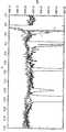
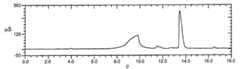
DX500 이온 크로마토그래피 시스템을 음이온 분석을 위해 사용하였다. 분석용 컬럼은 AS11 컬럼 4 x 250 mm이었고, 이를 다음 구배(05-38.25 mM)로 작동시켰다.DX500 ion chromatography system was used for anion analysis. The analytical column was an AS11 column 4 × 250 mm, which was operated with the next gradient (05-38.25 mM).
유량 =2ml/분
Flow rate = 2ml / min
억제기는 정상 재순환 모드에서 100mA의 적용 전류에서 작동하는 ASRS 울트라 억제기였다. 이 실시예는 정제 전후 수돗물이 첨가된 RO를 사용하여 크로마토크래피 성능을 비교한 것을 도시한 것이다. 도 2에 기재한 유형의 전기탈이온화기를 이 분석에 사용하였고, 상기 전기탈이온화기를 정전압 조건하에 12V에서 전력화하였다. 실험 셋업은 도 2와 유사하였고, 저장소 E1은 정제된 생성물 및 사전 정제수를 위한 저장소였다. 저장소를 사전 정제 실험 후에 잘 세척하였다. 이 실시예에서, 구배 초기에는 낮은 용리액 농도를 사용하였고 이러한 조건이 오염물질의 존재를 시험할 것이다. 정제 없이 수득된 크로마토그램은, 도 9a에 기재된 바와 같이 350 μS/cm의 전체 스케일 전도성 반응에서 클로라이드 및 설페이트에 대한 거대한 반응 값을 나타내었다. 오염물질로부터의 반응은 크로마토그램을 압도하였고 5종의 음이온 샘플 시험 혼합물에 대해 예상되는 분석물 반응은 관찰되지 않는다. 이들 조건하에서 행해진 분석은 설득력이 없다. 물의 정수는 분석물 반응의 회수를 가능하게 하였는데, 도 9b에 도시된 대로 전체 스케일 반응은 35μS/cm이었다. 본 발명의 전기탈이온화기는 물에서 오염물질 수준을 감소시키는데 아주 효과적이다.The suppressor was an ASRS ultra suppressor operating at 100 mA applied current in normal recycle mode. This example shows a comparison of chromatographic performance using RO with tap water added before and after purification. An electrodeionizer of the type described in FIG. 2 was used for this analysis, which was powered at 12V under constant voltage conditions. The experimental setup was similar to FIG. 2, with reservoir E1 being a reservoir for purified product and prepurified water. The reservoir was washed well after the pre-purification experiment. In this example, low eluent concentration was used at the beginning of the gradient and this condition would test for the presence of contaminants. The chromatogram obtained without purification showed huge reaction values for chloride and sulfate in a full scale conductivity reaction of 350 μS / cm as described in FIG. 9A. Reactions from contaminants overwhelmed the chromatogram and no expected analyte response was observed for the five anion sample test mixtures. Analysis conducted under these conditions is not convincing. The integer number of water allowed the recovery of the analyte reaction, with a full scale reaction of 35 μS / cm as shown in FIG. 9B. Electrodeionizers of the present invention are very effective in reducing pollutant levels in water.
실시예 6Example 6
DX500 이온 크로마토그래피 시스템을 양이온 분석을 위해 사용하였다. 분석용 컬럼은 CS12A 컬럼 4 x 250 mm이었다. 용리액은 수돗물이 첨가된 RO로 100-mM MSA 원농축물을 정제 전후에 분배함으로써 제조되었다. CSRS 울트라 억제기를 100mA의 전류 세팅에 사용하였다. 이 실험에서, 수질을 크로마토그래피로 정제하기 전후에 비교하였다. 전기탈이온화기는 도 1에 기재된 것과 동일한 장치였고, 실험 셋업은 도 2와 유사하였다. 결과는 도 10에 나타낸 바와 같이 수돗물이 첨가된 RO를 사용한 경우에 더 높은 백그라운드를 나타내었다. 또한, 암모니아에 대한 피크 반응은 사전 정제수보다 훨씬 낮았다. 이로부터 하기와 같은 설명이 가능하다: CSRS 억제기는 모든 음이온을 제거하고 양이온을 전도성 염기로 전환시킨다. 잔류 양이온으로부터의 백그라운드는 염기성이고, 염기성 조건하의 암모니아는 기체이며 기체를 발생시키는 경향이 있다. 따라서, 장치는 암모니아에 대해서는 반응성이 더 낮았다. 한편 정제수는 어떠한 효과도 나타내지 않았다.DX500 ion chromatography system was used for cation analysis. The analytical column was a CS12A column 4 x 250 mm. Eluent was prepared by dispensing 100-mM MSA concentrate with RO before tapping before and after purification. CSRS ultra suppressors were used for current settings of 100 mA. In this experiment, water quality was compared before and after purification by chromatography. The electrodeionizer was the same device as described in FIG. 1 and the experimental setup was similar to FIG. 2. The results showed a higher background when using RO with tap water as shown in FIG. 10. In addition, the peak response to ammonia was much lower than that of prepurified water. From this the following explanation is possible: CSRS inhibitors remove all anions and convert cations to conductive bases. The background from residual cations is basic, and ammonia under basic conditions is a gas and tends to generate gas. Thus, the device was less reactive with ammonia. On the other hand, purified water did not show any effect.
실시예 7Example 7
이 실험에서, 정제 전후에 수돗물이 첨가된 RO의 음이온 분석을 수행하였다. 밀리포어 정제수(RO에 이어 POU 연마제 MilliQPlus 시스템)를 또한 동일 조건을 사용하여 분석하였다. 실험 셋업은, 500-μL-주입 루프를 당해 분석에 사용하는 것을 제외하고는, 도 2와 유사하였다. 도 11에 기재된 결과에서, 본 발명의 장치를 사용한 경우에 탁월한 오염물 제거 효율이 나타났다. 수돗물은 이온 오염물질의 수준이 높은 것으로 나타났다. 밀리포어 정제수는 본 발명의 장치에 필적할 만한 성능을 나타내었다.In this experiment, anion analysis of RO with tap water added before and after purification was performed. Millipore purified water (RO followed by POU abrasive MilliQPlus system) was also analyzed using the same conditions. The experimental setup was similar to FIG. 2 except that a 500-μL-injection loop was used for this assay. In the results described in FIG. 11, excellent contaminant removal efficiency was observed when using the apparatus of the present invention. Tap water was found to have high levels of ionic contaminants. Millipore purified water showed comparable performance to the apparatus of the present invention.
실시예 8Example 8
이 실시예에서, 정제 전후에 수돗물이 첨가된 RO의 양이온 분석을 수행하였다. 밀리포어 정제수(RO에 이어 POU 연마제 MilliQPlus 시스템)를 또한 동일 조건을 사용하여 분석하였다. DX500 이온 크로마토그래피 시스템을 양이온 분석을 위해 사용하였다. 분석용 컬럼은 CS12A 컬럼 4 x 250 mm이었고 용리액은 1 ml/분에서 20 mM MSA였다. CSRS 울트라 억제기를 58mA의 전류 세팅에서 사용하였다. 500-μL-주입 루프를 샘플을 주입하는데 사용하였다. 도 12에 기재된 결과에서, 본 발명의 장치를 사용한 경우에 탁월한 오염물 제거 효율이 나타났다. 수돗물은 이온 오염물질의 수준이 높은 것으로 나타났다.In this example, cation analysis of RO to which tap water was added before and after purification was performed. Millipore purified water (RO followed by POU abrasive MilliQPlus system) was also analyzed using the same conditions. DX500 ion chromatography system was used for cation analysis. The analytical column was a CS12A column 4 × 250 mm and the eluent was 20 mM MSA at 1 ml / min. The CSRS ultra suppressor was used at a current setting of 58 mA. A 500-μL-injection loop was used to inject the sample. In the results described in Figure 12, excellent contaminant removal efficiency was observed when using the device of the present invention. Tap water was found to have high levels of ionic contaminants.
Claims (35)
Translated fromKoreanApplications Claiming Priority (3)
| Application Number | Priority Date | Filing Date | Title |
|---|---|---|---|
| US10/099,854US6808608B2 (en) | 2002-03-13 | 2002-03-13 | Water purifier and method |
| US10/099,854 | 2002-03-13 | ||
| PCT/US2003/007803WO2003078331A2 (en) | 2002-03-13 | 2003-03-13 | Electrodialytic water purifier with ion exchange material and method for emoving ionic contaminants |
Publications (2)
| Publication Number | Publication Date |
|---|---|
| KR20040091726A KR20040091726A (en) | 2004-10-28 |
| KR100985924B1true KR100985924B1 (en) | 2010-10-06 |
Family
ID=28039704
Family Applications (1)
| Application Number | Title | Priority Date | Filing Date |
|---|---|---|---|
| KR1020047014311AExpired - Fee RelatedKR100985924B1 (en) | 2002-03-13 | 2003-03-13 | Electrodialysis water purifier with ion exchange material and how to remove ion pollutants |
Country Status (7)
| Country | Link |
|---|---|
| US (1) | US6808608B2 (en) |
| EP (1) | EP1485325A2 (en) |
| JP (1) | JP4394957B2 (en) |
| KR (1) | KR100985924B1 (en) |
| AU (1) | AU2003214169B2 (en) |
| CA (1) | CA2478359C (en) |
| WO (1) | WO2003078331A2 (en) |
Families Citing this family (39)
| Publication number | Priority date | Publication date | Assignee | Title |
|---|---|---|---|---|
| US7147785B2 (en) | 2000-09-28 | 2006-12-12 | Usfilter Corporation | Electrodeionization device and methods of use |
| US6752927B2 (en)* | 2001-03-01 | 2004-06-22 | Dionex Corporation | Suppressed chromatography and salt conversion system |
| ES2361004T3 (en) | 2001-10-15 | 2011-06-13 | Siemens Water Technologies Holding Corp. | APPARATUS AND METHOD FOR PURIFICATION OF FLUIDS. |
| US7390386B2 (en)* | 2002-01-10 | 2008-06-24 | Dionez Corporation | Aqueous stream purifier and method of use |
| US7501061B2 (en) | 2002-10-23 | 2009-03-10 | Siemens Water Technologies Holding Corp. | Production of water for injection using reverse osmosis |
| US7517696B2 (en)* | 2003-01-30 | 2009-04-14 | Dionex Corporation | Chemical suppressors and method of use |
| US6929748B2 (en)* | 2003-03-28 | 2005-08-16 | Chemitreat Pte Ltd | Apparatus and method for continuous electrodeionization |
| US7846340B2 (en) | 2003-11-13 | 2010-12-07 | Siemens Water Technologies Corp. | Water treatment system and method |
| US20050103717A1 (en) | 2003-11-13 | 2005-05-19 | United States Filter Corporation | Water treatment system and method |
| US7563351B2 (en) | 2003-11-13 | 2009-07-21 | Siemens Water Technologies Holding Corp. | Water treatment system and method |
| US7582198B2 (en) | 2003-11-13 | 2009-09-01 | Siemens Water Technologies Holding Corp. | Water treatment system and method |
| US7083733B2 (en)* | 2003-11-13 | 2006-08-01 | Usfilter Corporation | Water treatment system and method |
| US7862700B2 (en) | 2003-11-13 | 2011-01-04 | Siemens Water Technologies Holding Corp. | Water treatment system and method |
| US8377279B2 (en) | 2003-11-13 | 2013-02-19 | Siemens Industry, Inc. | Water treatment system and method |
| US7604725B2 (en) | 2003-11-13 | 2009-10-20 | Siemens Water Technologies Holding Corp. | Water treatment system and method |
| US7329358B2 (en) | 2004-05-27 | 2008-02-12 | Siemens Water Technologies Holding Corp. | Water treatment process |
| US7399415B2 (en)* | 2004-09-02 | 2008-07-15 | Dionex Corporation | Parking a sample stream and suppressing the sample |
| US7892848B2 (en) | 2005-04-14 | 2011-02-22 | Trovion Singapore Pte. Ltd., Co. | Method of ion chromatography wherein a specialized electrodeionization apparatus is used |
| US20060231403A1 (en)* | 2005-04-14 | 2006-10-19 | Riviello John M | Chambered electrodeionization apparatus with uniform current density, and method of use |
| WO2006130786A2 (en) | 2005-06-01 | 2006-12-07 | Siemens Water Technologies Holding Corp. | Water treatment system and process |
| US20080067069A1 (en) | 2006-06-22 | 2008-03-20 | Siemens Water Technologies Corp. | Low scale potential water treatment |
| US7744760B2 (en) | 2006-09-20 | 2010-06-29 | Siemens Water Technologies Corp. | Method and apparatus for desalination |
| WO2008048656A2 (en)* | 2006-10-18 | 2008-04-24 | Kinetico Incorporated | Electroregeneration apparatus and water treatment method |
| WO2009073175A2 (en) | 2007-11-30 | 2009-06-11 | Siemens Water Technologies Corp. | Systems and methods for water treatment |
| US8293099B2 (en) | 2008-02-28 | 2012-10-23 | Dionex Corporation | Ion detector and system |
| US8133373B2 (en) | 2008-08-15 | 2012-03-13 | Dionex Corporation | Electrochemically driven pump |
| SG181244A1 (en) | 2010-11-12 | 2012-06-28 | Siemens Pte Ltd | Modular electrochemical systems and methods |
| US9724645B2 (en) | 2012-02-02 | 2017-08-08 | Tangent Company Llc | Electrochemically regenerated water deionization |
| US10048233B2 (en) | 2012-11-12 | 2018-08-14 | Dionex Corporation | Suppressor device |
| KR102093443B1 (en)* | 2012-11-29 | 2020-03-25 | 삼성전자주식회사 | Capacitive deionization apparatus and methods of treating fluid using the same |
| CA2904825A1 (en) | 2013-03-15 | 2014-09-18 | Evoqua Water Technologies Llc | Flow distributors for electrochemical separation |
| KR102092941B1 (en) | 2013-06-12 | 2020-03-24 | 삼성전자주식회사 | Capacitive deionization apparatus and methods of treating fluid using the same |
| US9625430B2 (en) | 2013-10-18 | 2017-04-18 | Dionex Corporation | Multielectrode electrolytic device and method |
| US11090606B2 (en) | 2013-12-05 | 2021-08-17 | Dionex Corporation | Gas-less electrolytic device and method |
| CA2873433A1 (en)* | 2014-12-05 | 2016-06-05 | Onsite Remediation Solutions Ltd. | Electrokinetic soil remediation |
| JP6733888B2 (en)* | 2016-08-26 | 2020-08-05 | 国立大学法人東海国立大学機構 | Ion exchange membrane electrodialysis device |
| US10948466B2 (en)* | 2017-03-03 | 2021-03-16 | Dionex Corporation | Flow control in an electrolytic reagent concentrator for ion chromatography |
| US20240159721A1 (en)* | 2022-11-14 | 2024-05-16 | Dionex Corporation | Chromatography Baseline Stability |
| WO2025165609A1 (en)* | 2024-01-29 | 2025-08-07 | The Johns Hopkins University | Electrochemical seawater desalination with hydrogen depolarization |
Citations (1)
| Publication number | Priority date | Publication date | Assignee | Title |
|---|---|---|---|---|
| GB2249307A (en)* | 1990-10-30 | 1992-05-06 | Ionics Italba Spa | Process for purifying water by means of a combination of electrodialysis and reverse osmosis |
Family Cites Families (37)
| Publication number | Priority date | Publication date | Assignee | Title |
|---|---|---|---|---|
| BE504756A (en) | 1950-07-21 | |||
| US2815320A (en) | 1953-10-23 | 1957-12-03 | Kollsman Paul | Method of and apparatus for treating ionic fluids by dialysis |
| US2794777A (en) | 1956-08-27 | 1957-06-04 | Clayton Manufacturing Co | Electrolytic deionization |
| GB879181A (en) | 1958-02-03 | 1961-10-04 | Permutit Co Ltd | Improvements relating to the removal of dissolved solids from liquids |
| NL288721A (en) | 1962-02-19 | |||
| US3341441A (en) | 1964-01-07 | 1967-09-12 | Ionics | Method for preventing scale buildup during electrodialysis operation |
| US3869376A (en) | 1973-05-14 | 1975-03-04 | Alvaro R Tejeda | System for demineralizing water by electrodialysis |
| US4148708A (en) | 1977-07-22 | 1979-04-10 | The Babcock & Wilcox Company | Combination ion exchange and electrodialysis fluid purification apparatus |
| JPS59133459A (en)* | 1983-01-21 | 1984-07-31 | Hitachi Ltd | Ion chromatograph |
| US4931160A (en) | 1987-05-11 | 1990-06-05 | Millipore Corporation | Electrodeionization method and apparatus |
| US4956071A (en) | 1984-07-09 | 1990-09-11 | Millipore Corporation | Electrodeionization apparatus and module |
| US5154809A (en) | 1984-07-09 | 1992-10-13 | Millipore Corporation | Process for purifying water |
| EP0170895B1 (en) | 1984-07-09 | 1989-03-22 | Millipore Corporation | Improved electrodeionization apparatus and method |
| US4925541B1 (en) | 1984-07-09 | 1994-08-02 | Millipore Corp | Electrodeionization apparatus and method |
| AU587988B2 (en)* | 1984-10-04 | 1989-09-07 | Dionex Corporation | Modified membrane suppressor and method of use |
| US4999098A (en) | 1984-10-04 | 1991-03-12 | Dionex Corporation | Modified membrane suppressor and method for use |
| JPH01266810A (en)* | 1988-04-19 | 1989-10-24 | Tosoh Corp | Method and device for replacing electrolyte |
| JPH03144356A (en)* | 1989-10-31 | 1991-06-19 | Tosoh Corp | Pretreatment of cation analyzer |
| JPH04172244A (en)* | 1990-11-06 | 1992-06-19 | Tosoh Corp | Pretreatment method for anion analysis |
| DE69120295T2 (en) | 1990-12-17 | 1997-03-06 | Ionpure Filter Us Inc | ELECTRODEIONIZING DEVICE |
| DE69204187T2 (en) | 1991-03-13 | 1996-01-25 | Ebara Corp | Electrically regenerable demineralization device. |
| US5248426A (en) | 1992-02-10 | 1993-09-28 | Dionex Corporation | Ion chromatography system using electrochemical suppression and detector effluent recycle |
| US5503729A (en) | 1994-04-25 | 1996-04-02 | Ionics Incorporated | Electrodialysis including filled cell electrodialysis (electrodeionization) |
| JPH10500617A (en) | 1994-05-20 | 1998-01-20 | ユー・エス・フィルター/アイオンピュア・インコーポレーテッド | Electrode-ionization devices with polarity reversal and double reversal and their use |
| DE4418812C2 (en)* | 1994-05-30 | 1999-03-25 | Forschungszentrum Juelich Gmbh | Single and multiple electrolysis cells and arrangements thereof for the deionization of aqueous media |
| WO1996029133A1 (en) | 1995-03-23 | 1996-09-26 | Ionics, Incorporated | Improvements in membrane processes including electrodialysis |
| GB9607646D0 (en) | 1996-04-12 | 1996-06-12 | Elga Ltd | Apparatus and method of electrodialysis |
| US5868915A (en) | 1996-09-23 | 1999-02-09 | United States Filter Corporation | Electrodeionization apparatus and method |
| CA2232931C (en) | 1997-03-28 | 2008-05-20 | Asahi Glass Company Ltd. | Method for producing deionized water |
| JP2000140583A (en)* | 1998-09-08 | 2000-05-23 | Japan Organo Co Ltd | Electrical deionized-water production apparatus |
| US6077434A (en) | 1999-01-15 | 2000-06-20 | Dionex Corporation | Current-efficient suppressors and method of use |
| US6284124B1 (en) | 1999-01-29 | 2001-09-04 | United States Filter Corporation | Electrodeionization apparatus and method |
| US6241866B1 (en) | 1999-09-13 | 2001-06-05 | Leon Mir | Electrodeionization apparatus with fixed ion exchange materials |
| US6241867B1 (en) | 1999-09-13 | 2001-06-05 | Leon Mir | Electrodeionization apparatus and packing therefor |
| US6254753B1 (en) | 1999-09-13 | 2001-07-03 | Leon Mir | High purity electrodeionization |
| US6649037B2 (en)* | 2001-05-29 | 2003-11-18 | United States Filter Corporation | Electrodeionization apparatus and method |
| JP2003001258A (en)* | 2001-06-15 | 2003-01-07 | Kurita Water Ind Ltd | Electrodeionization equipment |
- 2002
- 2002-03-13USUS10/099,854patent/US6808608B2/ennot_activeExpired - Lifetime
- 2003
- 2003-03-13JPJP2003576346Apatent/JP4394957B2/ennot_activeExpired - Fee Related
- 2003-03-13AUAU2003214169Apatent/AU2003214169B2/ennot_activeCeased
- 2003-03-13KRKR1020047014311Apatent/KR100985924B1/ennot_activeExpired - Fee Related
- 2003-03-13EPEP03711576Apatent/EP1485325A2/ennot_activeWithdrawn
- 2003-03-13CACA2478359Apatent/CA2478359C/ennot_activeExpired - Fee Related
- 2003-03-13WOPCT/US2003/007803patent/WO2003078331A2/enactiveApplication Filing
Patent Citations (1)
| Publication number | Priority date | Publication date | Assignee | Title |
|---|---|---|---|---|
| GB2249307A (en)* | 1990-10-30 | 1992-05-06 | Ionics Italba Spa | Process for purifying water by means of a combination of electrodialysis and reverse osmosis |
Also Published As
| Publication number | Publication date |
|---|---|
| AU2003214169A1 (en) | 2003-09-29 |
| AU2003214169B2 (en) | 2008-10-02 |
| WO2003078331A2 (en) | 2003-09-25 |
| JP4394957B2 (en) | 2010-01-06 |
| KR20040091726A (en) | 2004-10-28 |
| JP2006500192A (en) | 2006-01-05 |
| EP1485325A2 (en) | 2004-12-15 |
| CA2478359C (en) | 2011-05-17 |
| WO2003078331A3 (en) | 2004-05-06 |
| CA2478359A1 (en) | 2003-09-25 |
| US6808608B2 (en) | 2004-10-26 |
| US20030173222A1 (en) | 2003-09-18 |
Similar Documents
| Publication | Publication Date | Title |
|---|---|---|
| KR100985924B1 (en) | Electrodialysis water purifier with ion exchange material and how to remove ion pollutants | |
| US8926818B2 (en) | Layered electrodeionization device with discreet cation chamber | |
| EP2286899B1 (en) | Electrolytic eluent generator and method of use | |
| US20060231403A1 (en) | Chambered electrodeionization apparatus with uniform current density, and method of use | |
| KR100918531B1 (en) | Chromatographic apparatus and electrolysis method for purifying an aqueous stream containing contaminating ions | |
| US20030127392A1 (en) | Eluent purifier and method of use | |
| EP2937690B1 (en) | Electrolytic device for contaminant removal and method | |
| EP1261866B1 (en) | Method and apparatus for gas-assisted suppressed chromatography | |
| US20160145125A1 (en) | Layered electrodeionization device with discreet anion chamber | |
| HK1152006A (en) | Electrolytic eluent generator and method of use | |
| HK1076267B (en) | Electrolytic eluent generator and method of use |
Legal Events
| Date | Code | Title | Description |
|---|---|---|---|
| PA0105 | International application | St.27 status event code:A-0-1-A10-A15-nap-PA0105 | |
| PG1501 | Laying open of application | St.27 status event code:A-1-1-Q10-Q12-nap-PG1501 | |
| A201 | Request for examination | ||
| P11-X000 | Amendment of application requested | St.27 status event code:A-2-2-P10-P11-nap-X000 | |
| P13-X000 | Application amended | St.27 status event code:A-2-2-P10-P13-nap-X000 | |
| PA0201 | Request for examination | St.27 status event code:A-1-2-D10-D11-exm-PA0201 | |
| E902 | Notification of reason for refusal | ||
| PE0902 | Notice of grounds for rejection | St.27 status event code:A-1-2-D10-D21-exm-PE0902 | |
| T11-X000 | Administrative time limit extension requested | St.27 status event code:U-3-3-T10-T11-oth-X000 | |
| T11-X000 | Administrative time limit extension requested | St.27 status event code:U-3-3-T10-T11-oth-X000 | |
| E13-X000 | Pre-grant limitation requested | St.27 status event code:A-2-3-E10-E13-lim-X000 | |
| P11-X000 | Amendment of application requested | St.27 status event code:A-2-2-P10-P11-nap-X000 | |
| P13-X000 | Application amended | St.27 status event code:A-2-2-P10-P13-nap-X000 | |
| E701 | Decision to grant or registration of patent right | ||
| PE0701 | Decision of registration | St.27 status event code:A-1-2-D10-D22-exm-PE0701 | |
| GRNT | Written decision to grant | ||
| PR0701 | Registration of establishment | St.27 status event code:A-2-4-F10-F11-exm-PR0701 | |
| PR1002 | Payment of registration fee | St.27 status event code:A-2-2-U10-U12-oth-PR1002 Fee payment year number:1 | |
| PG1601 | Publication of registration | St.27 status event code:A-4-4-Q10-Q13-nap-PG1601 | |
| R18-X000 | Changes to party contact information recorded | St.27 status event code:A-5-5-R10-R18-oth-X000 | |
| FPAY | Annual fee payment | Payment date:20130919 Year of fee payment:4 | |
| PR1001 | Payment of annual fee | St.27 status event code:A-4-4-U10-U11-oth-PR1001 Fee payment year number:4 | |
| FPAY | Annual fee payment | Payment date:20140919 Year of fee payment:5 | |
| PR1001 | Payment of annual fee | St.27 status event code:A-4-4-U10-U11-oth-PR1001 Fee payment year number:5 | |
| FPAY | Annual fee payment | Payment date:20150827 Year of fee payment:6 | |
| PR1001 | Payment of annual fee | St.27 status event code:A-4-4-U10-U11-oth-PR1001 Fee payment year number:6 | |
| FPAY | Annual fee payment | Payment date:20160831 Year of fee payment:7 | |
| PR1001 | Payment of annual fee | St.27 status event code:A-4-4-U10-U11-oth-PR1001 Fee payment year number:7 | |
| LAPS | Lapse due to unpaid annual fee | ||
| PC1903 | Unpaid annual fee | St.27 status event code:A-4-4-U10-U13-oth-PC1903 Not in force date:20171001 Payment event data comment text:Termination Category : DEFAULT_OF_REGISTRATION_FEE | |
| PC1903 | Unpaid annual fee | St.27 status event code:N-4-6-H10-H13-oth-PC1903 Ip right cessation event data comment text:Termination Category : DEFAULT_OF_REGISTRATION_FEE Not in force date:20171001 |