KR100983332B1 - Light guide panel and backlight unit using the same - Google Patents
Light guide panel and backlight unit using the sameDownload PDFInfo
- Publication number
- KR100983332B1 KR100983332B1KR1020080084438AKR20080084438AKR100983332B1KR 100983332 B1KR100983332 B1KR 100983332B1KR 1020080084438 AKR1020080084438 AKR 1020080084438AKR 20080084438 AKR20080084438 AKR 20080084438AKR 100983332 B1KR100983332 B1KR 100983332B1
- Authority
- KR
- South Korea
- Prior art keywords
- light
- light guide
- guide plate
- pattern
- horseshoe
- Prior art date
- Legal status (The legal status is an assumption and is not a legal conclusion. Google has not performed a legal analysis and makes no representation as to the accuracy of the status listed.)
- Expired - Fee Related
Links
Images


Classifications
- G—PHYSICS
- G02—OPTICS
- G02B—OPTICAL ELEMENTS, SYSTEMS OR APPARATUS
- G02B6/00—Light guides; Structural details of arrangements comprising light guides and other optical elements, e.g. couplings
- G—PHYSICS
- G02—OPTICS
- G02B—OPTICAL ELEMENTS, SYSTEMS OR APPARATUS
- G02B5/00—Optical elements other than lenses
- G02B5/04—Prisms
- G02B5/045—Prism arrays
- G—PHYSICS
- G02—OPTICS
- G02B—OPTICAL ELEMENTS, SYSTEMS OR APPARATUS
- G02B5/00—Optical elements other than lenses
- G02B5/02—Diffusing elements; Afocal elements
- G—PHYSICS
- G02—OPTICS
- G02B—OPTICAL ELEMENTS, SYSTEMS OR APPARATUS
- G02B6/00—Light guides; Structural details of arrangements comprising light guides and other optical elements, e.g. couplings
- G02B6/0001—Light guides; Structural details of arrangements comprising light guides and other optical elements, e.g. couplings specially adapted for lighting devices or systems
- G02B6/0011—Light guides; Structural details of arrangements comprising light guides and other optical elements, e.g. couplings specially adapted for lighting devices or systems the light guides being planar or of plate-like form
- G02B6/0033—Means for improving the coupling-out of light from the light guide
- G02B6/0035—Means for improving the coupling-out of light from the light guide provided on the surface of the light guide or in the bulk of it
- G02B6/0036—2-D arrangement of prisms, protrusions, indentations or roughened surfaces
- G—PHYSICS
- G02—OPTICS
- G02F—OPTICAL DEVICES OR ARRANGEMENTS FOR THE CONTROL OF LIGHT BY MODIFICATION OF THE OPTICAL PROPERTIES OF THE MEDIA OF THE ELEMENTS INVOLVED THEREIN; NON-LINEAR OPTICS; FREQUENCY-CHANGING OF LIGHT; OPTICAL LOGIC ELEMENTS; OPTICAL ANALOGUE/DIGITAL CONVERTERS
- G02F1/00—Devices or arrangements for the control of the intensity, colour, phase, polarisation or direction of light arriving from an independent light source, e.g. switching, gating or modulating; Non-linear optics
- G02F1/01—Devices or arrangements for the control of the intensity, colour, phase, polarisation or direction of light arriving from an independent light source, e.g. switching, gating or modulating; Non-linear optics for the control of the intensity, phase, polarisation or colour
- G02F1/13—Devices or arrangements for the control of the intensity, colour, phase, polarisation or direction of light arriving from an independent light source, e.g. switching, gating or modulating; Non-linear optics for the control of the intensity, phase, polarisation or colour based on liquid crystals, e.g. single liquid crystal display cells
- G02F1/133—Constructional arrangements; Operation of liquid crystal cells; Circuit arrangements
- G02F1/1333—Constructional arrangements; Manufacturing methods
- G02F1/1335—Structural association of cells with optical devices, e.g. polarisers or reflectors
Landscapes
- Physics & Mathematics (AREA)
- General Physics & Mathematics (AREA)
- Optics & Photonics (AREA)
- Nonlinear Science (AREA)
- Mathematical Physics (AREA)
- Chemical & Material Sciences (AREA)
- Crystallography & Structural Chemistry (AREA)
- Planar Illumination Modules (AREA)
- Light Guides In General And Applications Therefor (AREA)
Abstract
Translated fromKoreanDescription
Translated fromKorean본 발명은 액정디스플레이(Liquid Crystal Display: LCD) 장치의 백라이트 유닛에 관한 것으로, 특히 확산필름 및 프리즘 시트를 적용하지 않고 향상된 휘도 및 광시야각을 제공할 수 있는 도광판 및 이를 이용한 백라이트 유닛에 관한 것이다.BACKGROUND OF THE
일반적으로, LCD 소자는 인가 전압에 따른 액정 투과도의 변화를 이용하여 각종 장치에서 발생되는 여러 가지 전기적인 정보를 시각정보로 변화시키는 전자소자이다. LCD 소자는 각종 정보를 표시하는 소자이면서도 자체 광원이 없으면 시각화할 수 없다. 따라서 텔레비전 및 노트북 등에 사용되고 있는 액정표시장치는 LCD 소자에 표시되고 있는 정보를 시각화하기 위해서 그 후면에서 LCD 소자 전체에 수직으로 균일하게 광을 제공하는 백라이트 유닛(Back-Light Unit: BLU)을 포함한다.In general, LCD devices are electronic devices that change various electrical information generated by various devices into visual information by using a change in liquid crystal transmittance according to an applied voltage. LCD devices display various information and cannot be visualized without their own light source. Accordingly, liquid crystal displays used in televisions and laptops include a back-light unit (BLU) that uniformly provides light vertically to the entire LCD element from the rear thereof in order to visualize information displayed on the LCD element. .
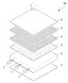
도 1은 일반적인 백라이트 유닛의 개략적인 구성을 나타낸 도면이다.1 is a view showing a schematic configuration of a general backlight unit.
도 1에 도시된 바와 같이 백라이트 유닛(10)은 반사판(1)과 도광판(2)과 확 산필름(3)과 제1미세패턴 시트(4)와 제2미세패턴 시트(5)와 보호 시트(6)와 광원(7)으로 구성된다.As shown in FIG. 1, the
광원(7)에서 방출된 빛은 도광판(2)으로 입사된 후, 도광판(2) 내부에서 전반사를 일으키며 진행하며, 도광판(2)의 내부 하면에 형성된 반사패턴에 의해 산란된다. 반사패턴에 의해 산란된 광들 중 임계각 보다 작은 각도의 입사각으로 도광판 내부의 표면에 입사되는 광은 전반사되지 않고 투과되므로, 상측과 하측으로 방출된다. 일반적으로, 도광판(2)을 통해 방출되는 광의 출사각은 도광판(2)의 상부면을 기준으로 30도 정도로 매우 낮다.After the light emitted from the
반사판(1)은 하측으로 방출된 광을 반사하여 도광판(3)으로 재 입사시켜 광효율을 향상시킨다.The reflecting
확산필름(3)은 상기 도광판(2)의 상부면을 통해 방출되는 광을 확산 및 집광시켜 휘도를 균일하게 하고, 시야각을 넓혀준다. 그러나 확산필름(4)을 통과한 광은 휘도가 급격히 떨어진다.The
제1미세패턴 시트(4)는 확산필름(4)으로부터 낮은 각도로 입사되는 광을 굴절시켜 LCD 소자에 수직으로 입사하도록 1차 집광하여 방출하므로 확산필름(4)에 의해 급격히 떨어진 휘도 및 출사각을 높여준다. 통상 제1미세패턴 시트(4)는 확산필름(4)으로부터 입사되는 광을 LCD 소자에 수직으로 방출하기 위해 상부면에 다수의 프리즘 패턴들이 배열된다. 통상 상기 프리즘 패턴은 꼭지각이 90도 내외인 삼각형 형상으로 형성된다.Since the first
제2미세패턴 시트(5)는 제1미세패턴 시트(4)에서 1차 집광된 광의 휘도 균일 성을 높이고 출사각을 더 높이기 위해 2차 집광하여 방출한다.The second
통상, 도광판(2)에서 방출되는 광의 출사각은 도광판(2) 면과 대략 30도이다. 따라서 제1미세패턴시트(4) 및 제2미세패턴시트(5)에서는 확산필름(3)을 통해 방출되는 광을 입사받아 광의 출사각이 대략 90도가 되도록 집광하여 방출한다.Usually, the emission angle of the light emitted from the
휘도 균일성을 높이기 위해서 제1미세패턴 시트(5)와 제2미세패턴 시트(6)는 각각의 프리즘 패턴들이 수직이 되도록 배치하는 것이 일반적이며, LCD 소자가 장착되는 장치의 특성에 따라 제1미세패턴 시트(4)만 사용될 수도 있고, 둘 모두 사용될 수도 있다.In order to improve the uniformity of luminance, the first
보호 필름(6)은 제1미세패턴 시트(4) 상부 또는 제2미세패턴 시트(5) 상부에 위치하여 제1미세패턴 시트(4) 또는 제2미세패턴 시트(5)에 스크래치(scratch)가 발생하는 것을 방지한다.The
상술한 바와 같이 종래 백라이트 유닛은 LCD 소자의 저면으로 입사하는 광이 수직으로 제공되어야 한다. 그러나 도광판에서 출사되는 도광판을 기준으로 한 광의 출사각이 30도 정도로 매우 낮기 때문에 확산시트, 적어도 하나 이상의 미세패턴 시트를 필요로 하므로 백라이트 유닛을 박형화 하기 어려운 문제점이 있었다.As described above, in the conventional backlight unit, light incident on the bottom of the LCD element must be provided vertically. However, since the emission angle of light based on the light guide plate emitted from the light guide plate is very low, about 30 degrees, a diffusion sheet and at least one fine pattern sheet are required, which makes it difficult to reduce the backlight unit.
또한, 종래 백라이트 유닛에서는 열팽창 계수가 높은 확산필름(3) 및 제1미세패턴 필터(4) 및 제2미세패턴 필터(5)가 광원에 의해 발생하는 열에 의해 연신되므로 주름이 발생하여 특성저하가 발생할 수 있는 문제점이 있었다.In addition, in the conventional backlight unit, since the
또한, 종래 백라이트 유닛의 미세패턴 시트들 및 확산 시트의 사용은 백라이트 유닛 조립공정을 복잡하게 할 뿐만 아니라 절단 및 조립 시에 불량을 유발할 수 있는 문제점이 있었다.In addition, the use of the micropattern sheets and the diffusion sheet of the conventional backlight unit not only complicates the backlight unit assembly process but also has a problem that may cause defects in cutting and assembly.
따라서, 본 발명의 목적은 도광판 하부면에 음각의 말굽 모양의 반사패턴을 형성하고, 도광판 상부면에 확산 또는 집광패턴을 형성하여 확산필름 및 프리즘 시트를 적용하지 않고도 향상된 휘도 및 광시야각을 제공할 수 있는 도광판 및 이를 이용한 백라이트 유닛을 제공하는데 그 목적이 있다.Accordingly, an object of the present invention is to form a negative horseshoe reflection pattern on the lower surface of the light guide plate, and to form a diffused or condensed pattern on the upper surface of the light guide plate to provide improved luminance and wide viewing angle without applying a diffusion film and a prism sheet. An object of the present invention is to provide a light guide plate and a backlight unit using the same.
상기와 같은 목적을 달성하기 위한 본원 발명의 도광판은; 다수의 반사패턴이 하부면에 음각으로 형성되어 입사되는 광을 상부면으로 방출하는 도광판에 있어서, 상기 반사패턴은 양 단부면을 갖는 말굽형상을 가지며, 상기 반사패턴의 말굽형상의 내측에 5:1 내지 20:1 사이의 곡률로 형성되어 광을 집광 및 확산하는 내측면과 외측에 형성되는 외측면이 각각 내측 밑각 및 외측 밑각을 가지도록 경사지게 형성하되, 상기 내측면은 일방향으로 배열되고 상기 양 단부면은 상기 내측면이 배열된 일방향을 향하여 하향 경사진 것을 특징으로 한다.
여기서, 상기 말굽형상의 반사패턴의 단면이 삼각형 형상 또는 사다리꼴 형상으로 형성하는 것이 바람직하다.The light guide plate of the present invention for achieving the above object; A light guide plate in which a plurality of reflective patterns are formed intaglio on a bottom surface to emit incident light to the top surface, wherein the reflective pattern has a horseshoe shape having both end surfaces, and a 5: inside the horseshoe shape of the reflective pattern. It is formed with a curvature of 1 to 20: 1 and formed to be inclined so that the inner surface for collecting and diffusing light and the outer surface formed on the outside have an inner bottom angle and an outer bottom angle, respectively, wherein the inner surface is arranged in one direction and the amount The end face is characterized in that the inner side is inclined downward toward one direction arranged.
Here, the cross section of the horseshoe-shaped reflection pattern is preferably formed in a triangular shape or trapezoidal shape.
삭제delete
삭제delete
상기 내측 밑각이 10도 내지 80도가 되도록 형성하고, 상기 외측 밑각이 10 도 내지 50도가 되도록 형성하는 것이 바람직하다.It is preferable that the inner bottom angle is formed to be 10 degrees to 80 degrees, and the outer bottom angle is formed to be 10 degrees to 50 degrees.
상기 사다리꼴 형상의 반사패턴의 윗변에 대응하는 상부면에 부가패턴을 형성하는 것이 바람직하다.It is preferable to form an additional pattern on the upper surface corresponding to the upper side of the trapezoidal reflection pattern.
상기 도광판의 상부면에 확산패턴들을 형성하는 것이 바람직하다.It is preferable to form diffusion patterns on an upper surface of the light guide plate.
본 발명의 다른 실시 예에 따른 백라이트 유닛은; 일측면에 위치하는 광원과 하부면에 음각의 반사패턴을 가지는 도광판을 포함하는 백라이트 유닛에 있어서,
상기 반사패턴은 양 단부면을 가지는 말굽형상을 가지며, 상기 말굽형상의 반사패턴의 내측에 5:1 내지 20:1 사이의 곡률로 형성되어 광을 집광 및 확산하는 내측면과 외측에 형성되는 외측면이 각각 내측 밑각 및 외측밑각을 가지도록 경사지게 형성하되, 상기 반사패턴들의 내측면이 상기 광원이 배치된 측면을 향하도록 배열되고 상기 양 단부면은 상기 광원이 배치된 측면을 향하여 하향 경사진것을 특징으로 한다.A backlight unit according to another embodiment of the present invention; In the backlight unit including a light guide plate having a light source located on one side and a negative reflective pattern on the lower surface,
The reflective pattern has a horseshoe shape having both end faces, and is formed on the inner side of the horseshoe reflective pattern with a curvature of between 5: 1 and 20: 1 to be formed on the inner side and the outer side for collecting and diffusing light. The side surfaces are inclined so as to have an inner bottom angle and an outer bottom angle, respectively, wherein the inner surfaces of the reflective patterns are arranged to face the side where the light source is disposed, and both end surfaces are inclined downward toward the side where the light source is disposed. It features.
이상에서 설명한 바와 같이, 본 발명은 확산필름과 미세패턴 시트 등의 광학필름 없이도 도광판만으로 광원에서 방출된 광을 확산 및 집광할 수 있으므로 백라이트를 박형화 할 수 있는 효과가 있다.As described above, the present invention can diffuse and condense the light emitted from the light source with only the light guide plate without the optical film such as the diffusion film and the fine pattern sheet, thereby reducing the backlight thickness.
또한, 본 발명은 백라이트를 구성하는 부품수의 감소 및 공정 수 감소에 따라 제조 비용을 절약할 수 있는 효과가 있다.In addition, the present invention has the effect of reducing the manufacturing cost according to the reduction of the number of parts and the number of processes constituting the backlight.
이하 도면을 참조하여 본 발명에 따른 백라이트 유닛의 구성을 설명한다.Hereinafter, a configuration of a backlight unit according to the present invention will be described with reference to the drawings.
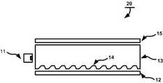
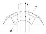
도 2는 본 발명에 따른 백라이트 유닛의 개략적인 구성을 나타낸 도면이다.2 is a view showing a schematic configuration of a backlight unit according to the present invention.
본 발명에 따른 백라이트 유닛(20)은 광원(11)과 반사시트(12)와 도광판(13)과 보호시트(14)를 포함한다.The
광원(11)은 최초로 광을 발산하는 부분이다. 광원(11)으로는 LED(Light Emitting Diode), 냉음극형광램프(Cold Cathode Fluorescent Lamp: CCFL) 등이 사용된다.The
도광판(13)은 내부 하단에 본 발명에 따른 말굽형상의 반사패턴(14)들을 구비하여 광원(11)에서 방출된 광을 산란 및 집광하여 상측으로 방출한다. 구체적으로 광원(11)에서 방출된 광은 도광판(13) 내부로 입사한 후, 도광판(13) 내부에서 전반사를 일으키며 진행하며, 본 발명에 따른 도광판(13)의 하부면에 음각으로 형성된 말굽형상의 반사패턴(14)에 부딪쳐 광의 입사각에 따라 반사되어 집광된다. 말굽형상의 반사패턴(14)에 의해 집광된 광들은 통상 임계각 보다 작은 각도의 입사각으로 도광판(13) 내측의 상부 표면에 입사되므로 전반사되지 않고 투과되어 상측으로 방출된다. 또한, 광은 내부에서 산란하게 되며, 산란하는 광들 중 임계각 보다 작은 각도의 입사각으로 도광판(13) 내부 면에 입사되면 도광판(13)을 투과하여 상측 및 하측으로 방출된다. 이때, 도광판(13)의 상측으로 방출된 광은 보호시트(15)로 입사하고, 하측으로 방출되는 광은 반사시트(12)로 입사한다.The
반사시트(12)는 도광판(13)의 하측으로부터 입사되는 광을 반사하여 도광판(13)으로 재 입사시킨다.The
보호시트(15)는 도광판(13)에 스크래치가 발생하는 것을 방지하며, 도광 판(13)으로부터 출사되는 광을 확산하여 LCD 소자에 수직하는 방향으로 출사한다.The
도 2에서는 나타내지 않았으나 시야각을 넓히거나 휘도를 높이거나 휘도 균일성을 향상시키기 위해 도광판(13)과 보호시트(15) 사이에 미세패턴 시트 또는 확산시트를 부가적으로 구성할 수도 있다.Although not shown in FIG. 2, a fine pattern sheet or a diffusion sheet may be additionally configured between the
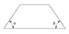
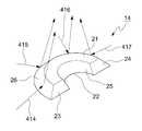
도 3a는 본 발명에 따라 말굽형상의 반사패턴의 단면이 사다리꼴 형상을 가지는 경우를 나타낸 도면이고, 도 3b는 본 발명에 따른 말굽형상 반사패턴의 단면도를 나타낸 도면이며, 도 3c는 본 발명에 따른 말굽형상 반사패턴의 내측면이 형성하는 호의 곡률을 나타낸 도면이고, 도 4a는 본 발명에 따른 반사패턴에서 광 반사에 따른 광경로의 일예를 나타낸 도면이고, 도 4b는 본 발명에 따른 반사패턴의 내측면에서의 집광에 따른 광경로의 일예를 나타낸 도면이며, 도 4c는 본 발명에 따른 말굽형상 반사패턴을 투과된 광 및 대광부에서 입사하는 광 경로의 일예를 나타낸 도면이고, 도 4d는 본 발명에 따른 말굽형상 반사패턴의 외측면에 의한 광 경로의 일예를 나타낸 도면이다. 그리고 도 5a는 본 발명에 따른 말굽형상의 반사패턴의 제1배열 예를 나타낸 도면이고, 도 5b는 본 발명에 따른 말굽형상의 반사패턴의 제2배열 예를 나타낸 도면이다. 이하 도 3 내지 도 5를 참조하여, 본 발명에 따른 말굽형상의 반사패턴 구조를 설명한다.Figure 3a is a view showing a cross-section of the horseshoe-shaped reflective pattern according to the invention has a trapezoidal shape, Figure 3b is a view showing a cross-sectional view of the horseshoe-shaped reflective pattern according to the invention, Figure 3c according to the present invention Figure 4a shows the curvature of the arc formed on the inner surface of the horseshoe-shaped reflection pattern, Figure 4a is a view showing an example of the optical path according to the light reflection in the reflection pattern according to the invention, Figure 4b is a view of the reflection pattern according to the present invention Figure 4c is a view showing an example of the optical path according to the condensing on the inner surface, Figure 4c is a view showing an example of the light path incident from the transmitted light and the light portion the horseshoe shape reflective pattern according to the present invention, Figure 4d Figure 1 shows an example of the optical path by the outer surface of the horseshoe shape reflective pattern according to the invention. 5A is a view showing a first arrangement example of a horseshoe-shaped reflection pattern according to the present invention, Figure 5B is a view showing a second arrangement example of a horseshoe-shaped reflection pattern according to the present invention. Hereinafter, the horseshoe shape reflective pattern structure according to the present invention will be described with reference to FIGS. 3 to 5.
본 발명에 따른 말굽형상의 반사패턴(14)은 도 3b에서와 같이 단면, 즉 사다리꼴 단면을 가지며, 사다리꼴 단면의 폭(W)이 50um이고 높이(H)가 40um를 가지도록 형성될 수 있다. 단면이 사다리꼴 형상인 말굽형상의 반사패턴(14)은 도 3a에서와 같이 상부면(21)과 하부면(22)과 제1전방단부면(23)과 제2전방단부면(24)과 내 측면(25)과 외측면(26)으로 구성된다.The horseshoe-shaped
내측면(25)은 전방, 즉 광원(11)이 위치한 측면 방향에 대해 경사지게 누워 있는 형태를 가지도록 구성된다. 도 3b의 말굽형상의 반사패턴의 단면을 참조하여 설명하면, 내측면(25)은 도 3b의 반사패턴(14)의 내측 밑각인 내측 밑각(α)만큼 경사도를 유지하면서 전방을 향하여 오목한 형상을 갖도록 형성된다. 상기 내측면(25)은 도 3c에서 보이는 바와 같이 폭(W)과 높이(H)에 의해 결정되는 곡률을 갖는 곡면 또는 도 4b에서와 같이 부분적 평면의 연속으로 형성될 수 있다. 이렇게 형성된 내측면(25)은 도 4에서와 같이 도광판(13) 내에서 전반사 중이거나 산란 중인 광을 집광하여 도광판(13)의 상측으로 방출한다. 다시 말하면, 내측면(25)은 광을 집광 및 확산하는 기능을 수행하여 좌우 시야각을 향상시킨다.The
상기 내측면(25)에 의해 반사된 광들 중 도 4a에서와 같이 임계각 보다 작은 각도의 입사각으로 도광판(13)의 상측으로 입사하는 광은 도광판(13)을 투과하여 LCD 소자에 수직하는 방향으로 방출된다.Among the lights reflected by the
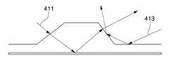
외측면(26) 또한 일정 경사도로 누워 있는 형태를 가지도록 구성된다. 도 3b를 참조하면, 외측면(26)은 외측 밑각(β)만큼 경사도를 유지하면서 후방을 향하여 볼록한 형상을 갖도록 형성된다. 이렇게 형성된 외측면(26)은 전반사 하면서 진행 중인 광을 반사하여 산란시키거나 산란 중인 광을 다시 반사한다. 구체적으로 도 4c 및 도 4d를 참조하면, 산란된 광들 중 도 4c의 광(411)과 같이 입사각이 임계각보다 작은 광은 반사패턴(14)을 투과할 수 있고, 투과된 광(411-1)은 반사시트(12)에 반사되고, 반사된 광(411-2)은 외측면(26)에 의해 굴절되어 도광판(13)의 상측 으로 방출된다. 또한, 전반사 진행하거나, 산란된 광들 중 광원(11)이 위치하는 곳과 대향되는 대광부쪽에서 반사된 광(413)은 외측면(26)에 의해 반사되어 도광판(13) 상측으로 진행한다. 또한, 도 4d와 같이 내측면(25)을 제외한 대광부 및 타 패턴에 반사되어 입사하는 광은 원형의 볼록한 형상을 가지는 외측면(26)을 통해 반사하여 도광판(13) 상측으로 진행한다. 즉, 외측면(26)은 내측면(25)으로 입사하는 광을 제외한 모든 방면에서 입사하는 광에 대해 고른 반사면을 형성한다.The
한편, 말굽형상의 반사패턴의 단면이 사다리꼴 형상인 경우, 제1전방단부면(23)과 제2전방단부면(24)도 사다리꼴 형상을 가진다. 제1전방단부면(23)과 제2전방단부면(24)은 동일한 모양 및 동일한 크기를 가지도록 형성할 수 있으며, 광 입사 방향에 대해 일정 경사도(θ)로 누워 있는 형태로 구성된다. 제1전방단부면(23)과 제2전방단부면(24)의 윗변은 각각 상부면(21)의 양 끝단에 대응되고, 아랫변은 각각 하부면(22)의 양 끝단에 대응된다. 이러한 제1전방단부면(23)과 제2전방단부면(24)은 전반사 중인 광을 반사하여 산란시키거나 산란중인 광을 재 반사시킨다. 상기 경사도(θ)는 외측 밑각 또는 내측 밑각과 동일한 값을 가질 수 있다.On the other hand, when the cross section of the horseshoe-shaped reflection pattern is trapezoidal, the first
상술한 말굽모양의 반사패턴(14)을 형성하는 방법으로는 핫프레스, 식각 등이 있다.The method of forming the horseshoe-shaped
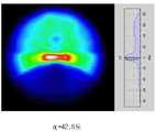
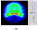
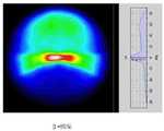
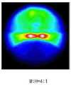
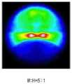
도 9는 본 발명의 말굽형상 반사패턴의 내측 밑각의 변화에 따른 휘도 및 시야각 특성을 나타낸 도면이고, 도 10은 본 발명의 말굽형상 반사패턴의 외측 밑각의 변화에 따른 휘도 및 시야각 특성을 나타낸 도면이다.9 is a view showing the brightness and viewing angle characteristics according to the change of the inner bottom angle of the horseshoe shape reflection pattern of the present invention, Figure 10 is a view showing the brightness and viewing angle characteristics according to the change of the outer bottom angle of the horseshoe shape reflection pattern of the present invention. to be.
도 9는 외측 밑각을 80도, 곡률을 5:1로 고정하고, 내측 밑각을 30도, 40도, 42.5도, 45도 및 50도에 대해 휘도 및 시야각 특성을 측정한 것이다. 또한, 도 10은 내측 밑각은 42.5도, 곡률을 5:1로 고정하고 외측 밑각을 40도 내지 80도의 범위에서 10도 간격으로 휘도 및 시야각 특성을 측정한 것이다.FIG. 9 measures luminance and viewing angle characteristics at an outer bottom angle of 80 degrees, a curvature of 5: 1, and an inner bottom angle of 30 degrees, 40 degrees, 42.5 degrees, 45 degrees, and 50 degrees. In addition, FIG. 10 measures luminance and viewing angle characteristics at intervals of 10 degrees at an inner bottom angle of 42.5 degrees, a curvature of 5: 1, and an outer bottom angle of 40 degrees to 80 degrees.
이와 같이, 본 발명에 따른 말굽형상의 반사패턴(14)에서는 내측면(25)의 경사도인 내측 밑각(α) 및 외측면(26)의 경사도인 외측 밑각(β)이 중요한 요소로 작용한다.As described above, in the horseshoe-shaped
도 9a와 같이 내측 밑각(α)이 30도인 경우 주 출사각이 +10도이고, 도 9b와 같이 40도인 경우에는 주출사각이 +5도이며, 도 9c와 같이 42.5도인 경우에는 주 출사각이 거의 0도이고, 도 9d와 같이 45도인 경우에는 주 출사각이 -5도내지 -7도이다. 그리고 도 9e와 같이 내측각이 50도인 경우에는 -20도에서 +60도까지 고른 집광효과 및 휘도 특성을 가지고, 주 출사각이 -10도임을 알 수 있다. 이외의 각도, 즉 내측 밑각(α)이 30도 미만이거나 5도를 초과하는 경우 주 출사각이 ㅁ 10도를 벗어남을 알 수 있다.As shown in FIG. 9A, when the inner bottom angle α is 30 degrees, the main exit angle is +10 degrees. In the case of 40 degrees as shown in FIG. 9B, the main exit angle is +5 degrees. In the case of almost 0 degrees and 45 degrees as shown in Fig. 9d, the main exit angle is -5 degrees to -7 degrees. In addition, as shown in FIG. 9E, when the inner angle is 50 degrees, it has a light condensing effect and luminance characteristics evened from -20 degrees to +60 degrees, and the main emission angle is -10 degrees. If the other angle, that is, the inner base angle α is less than 30 degrees or more than 5 degrees, it can be seen that the main exit angle is ㅁ 10 degrees.
따라서 내측 밑각(α)은 도 9에서 보이는 바와 같이 집광효과를 고려하여 상하 방향의 주 출사각이 수직(0도)에 비해 ㅁ 10도 안에 들어오도록 30도 내지 50도 사이의 임의의 각도로 형성하는 것이 바람직하다.Therefore, the inner bottom angle α is formed at an arbitrary angle between 30 degrees and 50 degrees so that the main emission angle in the vertical direction is within ㅁ 10 degrees compared to the vertical (0 degrees) in consideration of the light collecting effect as shown in FIG. 9. It is desirable to.
도 10a에서 외측 밑각이 40도인 경우로 시야각의 상측 부분의 집광효과가 떨어져 80도 대비 30%정도의 휘도 감소가 발생함을 알 수 있다.In FIG. 10A, when the outer base angle is 40 degrees, the light condensing effect of the upper portion of the viewing angle is lowered, and thus, the luminance decrease of about 30% compared to 80 degrees occurs.
따라서 외측 밑각(β)은 도 10에서 보이는 바와 같이 시야각 분포를 고려하여 집광효과가 큰 50도 내지 90도 사이의 임의의 각도로 형성하는 것이 바람직하 다.Therefore, the outer base angle β is preferably formed at any angle between 50 degrees and 90 degrees with a large light converging effect in consideration of the viewing angle distribution as shown in FIG. 10.
도 11은 본 발명의 말굽형상 반사패턴의 내측면의 곡률 변화에 따른 휘도 및 시야각 특성을 나타낸 것으로, 내측 밑각을 42.5도, 외측 밑각을 80도로 고정하고 곡률을 변화시키면서 휘도 및 시야각 특성을 측정한 것을 나타낸 것이다.11 is a view illustrating brightness and viewing angle characteristics according to a curvature change of an inner surface of a horseshoe-shaped reflection pattern of the present invention, and measuring the brightness and viewing angle characteristics while changing the curvature while fixing the inner bottom angle at 42.5 degrees and the outer bottom angle at 80 degrees It is shown.
도 11에서 보이는 바와 같이 말굽형상 반사패턴(14)의 내측면의 곡률(W:H)이 5:2, 5:3, 5:4 및 4:1일 때 좌우 시야각 분포가 갈라지고, 곡률이 5:1, 6:1, 10:1(5:0.5) 및 20:1일 때 좌우 시야각 분포가 갈라지지 않음을 알 수 있다. 다시 말하면, 곡률이 4:1 이하 및 20:1을 초과할 때는 좌우 시야각 분포가 갈라지고, 5:1 내지 20:1 사이에서는 좌우 시야각 분포가 갈라지지 않는다. 따라서, 본 발명에서는 좌우 시야각 분포가 갈라지지 않는, 즉 집광효과가 좋은 곡률의 폭 대 높이 비는 5:1 이상 20:1 이하가 되도록 하는 것이 바람직할 것이다.As shown in FIG. 11, when the curvature W: H of the inner surface of the
이러한 말굽형상의 반사패턴(14)은 도 5a에서와 같이 상하좌우 일정 거리를 두고 배열할 수도 있고, 도 5b에서와 같이 상하간에만 일정 거리를 두고 좌우로는 연속하는 형태로 배열할 수도 있다. 이외에도, 반사패턴(14)은 광원(11)에서 거리가 멀어질수록 거리를 단계적으로 줄이면서 배열할 수도 있다.The horseshoe-shaped
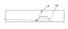
도 6은 본 발명에 따라 단면이 사다리꼴인 말굽형상의 반사패턴의 상부면에 부가패턴을 형성한 경우를 나타낸 도면이다.6 is a view showing a case in which an additional pattern is formed on the upper surface of the horseshoe-shaped reflection pattern of the trapezoidal cross section according to the present invention.
도 6을 참조하면, 본 발명에서 반사패턴(14)의 단면인 사다리꼴 형상의 윗변에 대응하는 말굽형상의 상부면(21)에 전반사 중이거나 산란 중인 광을 부가적으로 집광하기 위해 도 6과 같은 삼각 프리즘 형태의 부가패턴이 형성된다. 이외에도 부 가패턴으로, 다각형 패턴, 반원기둥 패턴 등이 형성될 수도 있다.Referring to FIG. 6, in order to additionally collect light, which is totally reflected or scattered, on the horseshoe-shaped
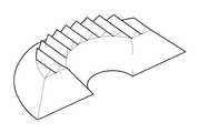
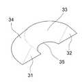
도 7은 본 발명에 따라 말굽형상의 반사패턴의 단면이 삼각형인 경우를 나타낸 것으로 도 7a는 단면이 삼각형인 말굽형상의 반사패턴을 나타낸 것이고, 도 7b는 말굽형상의 반사패턴의 단면을 나타낸 도면이다.7 is a cross-sectional view of the horseshoe-shaped reflection pattern according to the present invention is a triangle, Figure 7a shows a horseshoe-shaped reflection pattern of the triangle cross-section, Figure 7b is a view showing a cross section of the horseshoe-shaped reflection pattern to be.
도 7을 참조하면, 단면이 삼각형인 말굽형상의 반사패턴(14)은 제1전방단부면(31)과 제2전방단부면(32)과 내측면(33)과 외측면(34)과 하부면(35)으로 구성된다.Referring to FIG. 7, the horseshoe-shaped
도 7에 따른 반사패턴은 도 3에서 상부면(21)이 없는 것을 제외하면 나머지 형상과 기능은 동일하므로 중복되는 설명은 생략한다.Since the reflective pattern according to FIG. 7 has the same function as the remaining shapes except for the absence of the
상술한 도 7과 같은 삼각형 단면을 가지는 말굽형상의 반사패턴들 또한 도 4a 및 도 4b에서 나타낸 사다리꼴 단면을 가지는 말굽형상의 반사패턴들의 배열과 동일하게 배열할 수 있다.The horseshoe-shaped reflection patterns having a triangular cross section as shown in FIG. 7 may also be arranged in the same manner as the horseshoe-shaped reflection patterns having a trapezoidal cross section shown in FIGS. 4A and 4B.
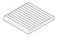
도 8은 본 발명에 따라 도광판 상부면에 구비되는 확산패턴 또는 집광패턴을 나타낸 도면이다.8 is a view illustrating a diffusion pattern or a light collecting pattern provided on an upper surface of the light guide plate according to the present invention.
도 8을 참조하면, 본 발명에 따른 말굽형상의 도광판(13) 상부면에 확산패턴 또는 집광패턴들을 더 형성하여, 도광판(13) 내부에서 집광된 광을 확산하거나 집광한다. 도 8a와 같이 프리즘 패턴이 형성될 수 있으며, 도 8b와 같은 반원기둥 및 도 8c와 같은 반원구 패턴이 형성될 수도 있다. 상기와 같은 확산패턴 및 집광패턴을 도광판(13) 상부면에 부가적으로 더 구성하므로써 휘도, 휘도 균일성 및 시야각을 향상시킬 수 있다.Referring to FIG. 8, diffusion patterns or condensing patterns are further formed on the top surface of the horseshoe-shaped
한편, 본 발명은 전술한 전형적인 바람직한 실시예에만 한정되는 것이 아니라 본 발명의 요지를 벗어나지 않는 범위 내에서 여러 가지로 개량, 변경, 대체 또는 부가하여 실시할 수 있는 것임은 당해 기술분야에서 통상의 지식을 가진 자라면 용이하게 이해할 수 있을 것이다. 이러한 개량, 변경, 대체 또는 부가에 의한 실시가 이하의 첨부된 특허청구범위의 범주에 속하는 것이라면 그 기술사상 역시 본 발명에 속하는 것으로 보아야 한다.On the other hand, the present invention is not limited to the above-described typical preferred embodiment, but can be carried out in various ways without departing from the gist of the present invention, various modifications, alterations, substitutions or additions in the art Anyone who has this can easily understand it. If such improvement, change, substitution or addition is carried out within the scope of the appended claims, the technical spirit should also be regarded as belonging to the present invention.
도 1은 일반적인 백라이트 유닛의 개략적인 구성을 나타낸 도면1 is a view showing a schematic configuration of a general backlight unit
도 2는 본 발명에 따른 백라이트 유닛의 개략적인 구성을 나타낸 도면2 is a view showing a schematic configuration of a backlight unit according to the present invention;
도 3a는 본 발명에 따른 단면이 사다리꼴인 말굽형상 반사패턴의 구성을 나타낸 도면Figure 3a is a view showing the configuration of a horseshoe-shaped reflective pattern of the trapezoidal cross section according to the present invention
도 3b는 도 3a의 말굽형상 반사패턴의 단면을 나타낸 도면3B is a cross-sectional view of the horseshoe shape reflection pattern of FIG. 3A;
도 3c는 도 3a의 말굽형상의 반사패턴의 내측면이 이루는 호의 곡률을 나타낸 도면Figure 3c is a view showing the curvature of the arc formed on the inner surface of the horseshoe shaped reflection pattern of Figure 3a
도 4a는 본 발명에 따른 반사패턴에서 광 반사에 따른 광경로의 일예를 나타낸 도면4A illustrates an example of an optical path according to light reflection in a reflection pattern according to the present invention;
도 4b는 본 발명에 따른 반사패턴의 내측면에서의 집광에 따른 광경로의 일예를 나타낸 도면4B is a view showing an example of an optical path according to condensing on the inner surface of the reflective pattern according to the present invention;
도 4c는 본 발명에 따라 반사패턴을 투과하는 광 및 대광부에서 입사하는 광의 광경로를 나타낸 도면Figure 4c is a view showing the optical path of the light passing through the reflection pattern and the light incident in accordance with the present invention;
도 4d는 본 발명에 따라 대광부 및 다른 반사패턴에서 입사하는 광의 광경로를 나타낸 도면4d is a view showing an optical path of light incident on a light portion and another reflection pattern according to the present invention;
도 5a는 본 발명에 따른 말굽형상의 반사패턴의 제1배열 예를 나타낸 도면5A is a view showing a first arrangement example of a horseshoe-shaped reflection pattern according to the present invention;
도 5b는 본 발명에 따른 말굽형상의 반사패턴의 제2배열 예를 나타낸 도면Figure 5b is a view showing a second arrangement example of the reflection pattern of the horseshoe shape according to the present invention
도 6은 본 발명에 따른 말굽형상의 반사패턴의 상부면에 부가패턴이 형성된 경우를 나타낸 도면6 is a view showing a case in which an additional pattern is formed on the upper surface of the horseshoe-shaped reflection pattern according to the present invention
도 7a는 본 발명에 따른 단면이 삼각형인 말굽형상 반사패턴의 구성을 나타낸 도면Figure 7a is a view showing the configuration of a horseshoe-shaped reflective pattern of the triangle is a cross section according to the present invention
도 7b는 도 7a의 말굽형상 반사패턴의 단면을 나타낸 도면FIG. 7B is a cross-sectional view of the horseshoe shape reflection pattern of FIG. 7A; FIG.
도 8a는 본 발명에 따른 도광판 상부면에 프리즘패턴을 구비하는 경우를 나타낸 도면8A is a view illustrating a case where a prism pattern is provided on an upper surface of a light guide plate according to the present invention.
도 8b는 본 발명에 따른 도광판 상부면에 반원통패턴을 구비하는 경우를 나타낸 도면8B is a view showing a case in which a semi-cylindrical pattern is provided on the upper surface of the light guide plate according to the present invention;
도 8c는 본 발명에 따른 도광판 상부면에 반원구패턴을 구비하는 경우를 나타낸 도면8C is a view illustrating a case in which a semi-circular sphere pattern is provided on an upper surface of a light guide plate according to the present invention;
도 9는 본 발명의 말굽형상의 반사패턴의 내측 밑각의 변화에 따른 휘도 및 시야각 특성을 나타낸 도면9 is a view showing the brightness and viewing angle characteristics according to the change of the inner bottom angle of the horseshoe-shaped reflection pattern of the present invention
도 10은 본 발명의 말굽형상의 반사패턴의 외측 밑각의 변화에 따른 휘도 및 시야각 특성을 나타낸 도면10 is a view showing the brightness and viewing angle characteristics according to the change of the outer bottom angle of the horseshoe-shaped reflection pattern of the present invention
도 11은 본 발명의 말굽형상의 반사패턴의 내측면이 이루는 호의 곡률(W:H) 변화에 따른 휘도 및 시야각 특성을 나타낸 도면11 is a view showing the luminance and viewing angle characteristics according to the change in curvature (W: H) of the arc formed on the inner surface of the horseshoe-shaped reflection pattern of the present invention
※ 도면의 주요 부분에 대한 부호의 설명[Description of Drawings]
1, 12 : 반사시트2, 13: 도광판1, 12:
3 : 확산시트4: 제1미세패턴 시트3: diffusion sheet 4: first fine pattern sheet
5: 제2미세패턴 시트6, 15: 보호시트5: 2nd
7, 11: 광원14: 반사패턴7, 11: light source 14: reflection pattern
21: 상부면22, 35: 하부면21:
23, 31: 제1전방단부면24, 32: 제2전방단부면23, 31: first
25, 33: 내측면26, 34: 외측면25, 33:
Claims (10)
Translated fromKoreanPriority Applications (2)
| Application Number | Priority Date | Filing Date | Title |
|---|---|---|---|
| KR1020080084438AKR100983332B1 (en) | 2008-08-28 | 2008-08-28 | Light guide panel and backlight unit using the same |
| PCT/KR2009/004795WO2010024610A2 (en) | 2008-08-28 | 2009-08-27 | Light guide plate and backlight unit based on same |
Applications Claiming Priority (1)
| Application Number | Priority Date | Filing Date | Title |
|---|---|---|---|
| KR1020080084438AKR100983332B1 (en) | 2008-08-28 | 2008-08-28 | Light guide panel and backlight unit using the same |
Publications (2)
| Publication Number | Publication Date |
|---|---|
| KR20100025759A KR20100025759A (en) | 2010-03-10 |
| KR100983332B1true KR100983332B1 (en) | 2010-09-20 |
Family
ID=41722131
Family Applications (1)
| Application Number | Title | Priority Date | Filing Date |
|---|---|---|---|
| KR1020080084438AExpired - Fee RelatedKR100983332B1 (en) | 2008-08-28 | 2008-08-28 | Light guide panel and backlight unit using the same |
Country Status (2)
| Country | Link |
|---|---|
| KR (1) | KR100983332B1 (en) |
| WO (1) | WO2010024610A2 (en) |
Cited By (1)
| Publication number | Priority date | Publication date | Assignee | Title |
|---|---|---|---|---|
| KR102803000B1 (en) | 2024-08-13 | 2025-05-09 | 주식회사 멤스룩스 | Light guide member and back light unit including the same |
Families Citing this family (1)
| Publication number | Priority date | Publication date | Assignee | Title |
|---|---|---|---|---|
| KR101721943B1 (en)* | 2015-04-20 | 2017-04-03 | 주식회사 엘엠에스 | Light Guiding Plate including Light Diffusion Parts and Back Light Unit Having the Same |
Citations (2)
| Publication number | Priority date | Publication date | Assignee | Title |
|---|---|---|---|---|
| US20060198598A1 (en)* | 2005-03-01 | 2006-09-07 | Wintek Corporation | Light-guide plate |
| JP2008027665A (en) | 2006-07-19 | 2008-02-07 | Nippon Leiz Co Ltd | Light guide plate and flat lighting device |
Family Cites Families (1)
| Publication number | Priority date | Publication date | Assignee | Title |
|---|---|---|---|---|
| KR20050115717A (en)* | 2004-06-04 | 2005-12-08 | 주식회사 파인옵틱스 | Light guide plate having light directing declined axis and fabrication methods thereof |
- 2008
- 2008-08-28KRKR1020080084438Apatent/KR100983332B1/ennot_activeExpired - Fee Related
- 2009
- 2009-08-27WOPCT/KR2009/004795patent/WO2010024610A2/enactiveApplication Filing
Patent Citations (2)
| Publication number | Priority date | Publication date | Assignee | Title |
|---|---|---|---|---|
| US20060198598A1 (en)* | 2005-03-01 | 2006-09-07 | Wintek Corporation | Light-guide plate |
| JP2008027665A (en) | 2006-07-19 | 2008-02-07 | Nippon Leiz Co Ltd | Light guide plate and flat lighting device |
Cited By (1)
| Publication number | Priority date | Publication date | Assignee | Title |
|---|---|---|---|---|
| KR102803000B1 (en) | 2024-08-13 | 2025-05-09 | 주식회사 멤스룩스 | Light guide member and back light unit including the same |
Also Published As
| Publication number | Publication date |
|---|---|
| KR20100025759A (en) | 2010-03-10 |
| WO2010024610A2 (en) | 2010-03-04 |
| WO2010024610A3 (en) | 2010-06-10 |
Similar Documents
| Publication | Publication Date | Title |
|---|---|---|
| JP4512137B2 (en) | Light guide plate for liquid crystal display device backlight unit and liquid crystal display device backlight unit using the same | |
| KR100978078B1 (en) | Prism sheet and liquid crystal display device having same | |
| KR100864321B1 (en) | Diffuser prism sheet including light diffuser having amorphous protrusions on the prism valleys and liquid crystal display device using the same | |
| JP5161892B2 (en) | Surface light source element and image display device having the same | |
| KR100903028B1 (en) | LGP for backlight unit of liquid crystal display including wedge back prism | |
| CN100561309C (en) | Light guide plate of liquid crystal display and backlight unit using same | |
| KR20030096509A (en) | Prism sheet and lcd having the same | |
| KR20160022220A (en) | Light guide plate, backlight unit and display device having the same | |
| KR100781328B1 (en) | Light guide plate for liquid crystal display device backlight unit and backlight unit for liquid crystal display device using same | |
| KR100661147B1 (en) | Light guide panel for LCD back light unit and LCD back light unit thereby | |
| KR100983332B1 (en) | Light guide panel and backlight unit using the same | |
| KR101037769B1 (en) | Optical film and backlight unit using same | |
| KR100869336B1 (en) | Side Dimming Backlight Unit | |
| US7751679B1 (en) | Brightness enhancement film and backlight module | |
| JP2007109625A (en) | Backlight device | |
| JP2007080800A (en) | Light guide plate of backlight unit | |
| JP2004325505A (en) | Back-lighting device and liquid crystal display device | |
| KR100980496B1 (en) | Hot spot improvement composite sheet and backlight unit using the same | |
| KR100790499B1 (en) | Side Dimming Backlight Unit | |
| KR100790498B1 (en) | Side Dimming Backlight Unit | |
| JP3981836B2 (en) | LCD panel lighting device | |
| KR101234841B1 (en) | Prism sheet having lengthwise wave patterned optical condensing portions and reflection portions, back light unit having the prism sheet and liquid crystal display device having the back light unit | |
| KR100869147B1 (en) | Light guide plate for backlight unit | |
| KR100742562B1 (en) | Light guide plate for liquid crystal display device and backlight unit for liquid crystal display device Diffusion sheet for backlight unit, backlight unit for liquid crystal display device using them, liquid crystal display device | |
| KR20070034751A (en) | Reflector, backlight assembly and liquid crystal display device having same |
Legal Events
| Date | Code | Title | Description |
|---|---|---|---|
| A201 | Request for examination | ||
| PA0109 | Patent application | St.27 status event code:A-0-1-A10-A12-nap-PA0109 | |
| PA0201 | Request for examination | St.27 status event code:A-1-2-D10-D11-exm-PA0201 | |
| R17-X000 | Change to representative recorded | St.27 status event code:A-3-3-R10-R17-oth-X000 | |
| D13-X000 | Search requested | St.27 status event code:A-1-2-D10-D13-srh-X000 | |
| D14-X000 | Search report completed | St.27 status event code:A-1-2-D10-D14-srh-X000 | |
| E902 | Notification of reason for refusal | ||
| PE0902 | Notice of grounds for rejection | St.27 status event code:A-1-2-D10-D21-exm-PE0902 | |
| PG1501 | Laying open of application | St.27 status event code:A-1-1-Q10-Q12-nap-PG1501 | |
| E13-X000 | Pre-grant limitation requested | St.27 status event code:A-2-3-E10-E13-lim-X000 | |
| P11-X000 | Amendment of application requested | St.27 status event code:A-2-2-P10-P11-nap-X000 | |
| P13-X000 | Application amended | St.27 status event code:A-2-2-P10-P13-nap-X000 | |
| E90F | Notification of reason for final refusal | ||
| PE0902 | Notice of grounds for rejection | St.27 status event code:A-1-2-D10-D21-exm-PE0902 | |
| P11-X000 | Amendment of application requested | St.27 status event code:A-2-2-P10-P11-nap-X000 | |
| P13-X000 | Application amended | St.27 status event code:A-2-2-P10-P13-nap-X000 | |
| E701 | Decision to grant or registration of patent right | ||
| PE0701 | Decision of registration | St.27 status event code:A-1-2-D10-D22-exm-PE0701 | |
| GRNT | Written decision to grant | ||
| PR0701 | Registration of establishment | St.27 status event code:A-2-4-F10-F11-exm-PR0701 | |
| PR1002 | Payment of registration fee | St.27 status event code:A-2-2-U10-U11-oth-PR1002 Fee payment year number:1 | |
| PG1601 | Publication of registration | St.27 status event code:A-4-4-Q10-Q13-nap-PG1601 | |
| R18-X000 | Changes to party contact information recorded | St.27 status event code:A-5-5-R10-R18-oth-X000 | |
| R18-X000 | Changes to party contact information recorded | St.27 status event code:A-5-5-R10-R18-oth-X000 | |
| FPAY | Annual fee payment | Payment date:20130913 Year of fee payment:4 | |
| PR1001 | Payment of annual fee | St.27 status event code:A-4-4-U10-U11-oth-PR1001 Fee payment year number:4 | |
| PR1001 | Payment of annual fee | St.27 status event code:A-4-4-U10-U11-oth-PR1001 Fee payment year number:5 | |
| FPAY | Annual fee payment | Payment date:20150820 Year of fee payment:6 | |
| PR1001 | Payment of annual fee | St.27 status event code:A-4-4-U10-U11-oth-PR1001 Fee payment year number:6 | |
| FPAY | Annual fee payment | Payment date:20160907 Year of fee payment:7 | |
| PR1001 | Payment of annual fee | St.27 status event code:A-4-4-U10-U11-oth-PR1001 Fee payment year number:7 | |
| LAPS | Lapse due to unpaid annual fee | ||
| PC1903 | Unpaid annual fee | St.27 status event code:A-4-4-U10-U13-oth-PC1903 Not in force date:20170915 Payment event data comment text:Termination Category : DEFAULT_OF_REGISTRATION_FEE | |
| PC1903 | Unpaid annual fee | St.27 status event code:N-4-6-H10-H13-oth-PC1903 Ip right cessation event data comment text:Termination Category : DEFAULT_OF_REGISTRATION_FEE Not in force date:20170915 |