KR100981362B1 - Junction box for solar cell module - Google Patents
Junction box for solar cell moduleDownload PDFInfo
- Publication number
- KR100981362B1 KR100981362B1KR1020100021758AKR20100021758AKR100981362B1KR 100981362 B1KR100981362 B1KR 100981362B1KR 1020100021758 AKR1020100021758 AKR 1020100021758AKR 20100021758 AKR20100021758 AKR 20100021758AKR 100981362 B1KR100981362 B1KR 100981362B1
- Authority
- KR
- South Korea
- Prior art keywords
- solar cell
- wire
- diode
- terminal
- cell module
- Prior art date
- Legal status (The legal status is an assumption and is not a legal conclusion. Google has not performed a legal analysis and makes no representation as to the accuracy of the status listed.)
- Expired - Fee Related
Links
Images


Classifications
- H—ELECTRICITY
- H02—GENERATION; CONVERSION OR DISTRIBUTION OF ELECTRIC POWER
- H02S—GENERATION OF ELECTRIC POWER BY CONVERSION OF INFRARED RADIATION, VISIBLE LIGHT OR ULTRAVIOLET LIGHT, e.g. USING PHOTOVOLTAIC [PV] MODULES
- H02S40/00—Components or accessories in combination with PV modules, not provided for in groups H02S10/00 - H02S30/00
- H02S40/30—Electrical components
- H02S40/34—Electrical components comprising specially adapted electrical connection means to be structurally associated with the PV module, e.g. junction boxes
- H02S40/345—Electrical components comprising specially adapted electrical connection means to be structurally associated with the PV module, e.g. junction boxes with cooling means associated with the electrical connection means, e.g. cooling means associated with or applied to the junction box
- Y—GENERAL TAGGING OF NEW TECHNOLOGICAL DEVELOPMENTS; GENERAL TAGGING OF CROSS-SECTIONAL TECHNOLOGIES SPANNING OVER SEVERAL SECTIONS OF THE IPC; TECHNICAL SUBJECTS COVERED BY FORMER USPC CROSS-REFERENCE ART COLLECTIONS [XRACs] AND DIGESTS
- Y02—TECHNOLOGIES OR APPLICATIONS FOR MITIGATION OR ADAPTATION AGAINST CLIMATE CHANGE
- Y02A—TECHNOLOGIES FOR ADAPTATION TO CLIMATE CHANGE
- Y02A30/00—Adapting or protecting infrastructure or their operation
- Y02A30/14—Extreme weather resilient electric power supply systems, e.g. strengthening power lines or underground power cables
- Y—GENERAL TAGGING OF NEW TECHNOLOGICAL DEVELOPMENTS; GENERAL TAGGING OF CROSS-SECTIONAL TECHNOLOGIES SPANNING OVER SEVERAL SECTIONS OF THE IPC; TECHNICAL SUBJECTS COVERED BY FORMER USPC CROSS-REFERENCE ART COLLECTIONS [XRACs] AND DIGESTS
- Y02—TECHNOLOGIES OR APPLICATIONS FOR MITIGATION OR ADAPTATION AGAINST CLIMATE CHANGE
- Y02E—REDUCTION OF GREENHOUSE GAS [GHG] EMISSIONS, RELATED TO ENERGY GENERATION, TRANSMISSION OR DISTRIBUTION
- Y02E10/00—Energy generation through renewable energy sources
- Y02E10/50—Photovoltaic [PV] energy
Landscapes
- Photovoltaic Devices (AREA)
Abstract
Translated fromKoreanDescription
Translated fromKorean본 발명은 다수의 태양전지에서 생산한 전기에너지를 수신하여 배터리로 전달하는 태양전지 모듈용 정션박스에 관한 것으로서, 특히, 다이오드를 이용하여 손상된 태양전지를 바이패스시키는 경우, 다이오드에서 발생한 열을 빠르게 방출하여 다이오드의 성능을 유지함과 아울러, 다이오드 및 제품 수명이 연장되도록 한 태양전지 모듈용 정션박스에 관한 것이다.The present invention relates to a junction box for a solar cell module that receives electrical energy produced by a plurality of solar cells and delivers them to a battery. In particular, when bypassing a damaged solar cell using a diode, heat generated from the diode is rapidly The present invention relates to a junction box for a solar cell module which emits and maintains the performance of the diode, and also extends the diode and product life.
일반적으로 태양전지 모듈은 복수 개의 태양전지가 배치된 패널이 다수 포함되어 이루어진다. 이때, 각 패널은 다수의 태양전지들을 구비하고 있고, 패널 내의 태양전지들은 직렬 또는 병렬로 연결되며, 이들 패널이 직렬로 연결되어 하나의 태양전지 모듈을 형성하게 된다.In general, a solar cell module includes a plurality of panels including a plurality of solar cells. At this time, each panel is provided with a plurality of solar cells, the solar cells in the panel are connected in series or in parallel, these panels are connected in series to form a single solar cell module.
그런데, 통상의 태양전지 모듈은 여러가지 장애요소들에 의해 손상되거나 차단되어 발전이 중지될 수 있다는 문제점이 있다. 즉, 조류 등의 배설물로 인해 태양전지가 손상되거나 그림자로 인해 원활한 발전이 이루어지지 않게 되는 것이다. 이렇게 손상되거나 차단된 태양전지가 포함된 패널에서는 전력전달 용량이 감소된다. 또한, 패널과 직렬로 연결된 다른 패널들로부터의 출력이 손상 또는 차단된 태양전지들을 향해 역으로 바이어싱하여 발전 자체가 중단될 수 있다.However, the conventional solar cell module has a problem that the power generation can be stopped by being damaged or blocked by various obstacles. In other words, due to the droppings of algae, such as damaging the solar cell or the shadow will not be smooth power generation. In panels with such damaged or blocked solar cells, power delivery capacity is reduced. In addition, the output from other panels connected in series with the panel can be biased back towards damaged or blocked solar cells, thereby interrupting power generation itself.
이러한 현상을 방지하기 위하여, 복수의 태양전지에서 발생한 전기에너지를 수신하여 배터리로 전달하는 장치인 정션박스에는, 각 태양전지를 연결하여 회로를 형성함과 아울러 파손 또는 차단된 태양전지를 바이패스하도록 하는 다이오드를 설치하고 있다.In order to prevent this phenomenon, a junction box, which is a device that receives electrical energy generated from a plurality of solar cells and delivers them to a battery, connects each solar cell to form a circuit and bypasses a damaged or blocked solar cell. To install a diode.
상기한 바이패스용 다이오드는, 복수의 태양전지 중 일부가 손상되거나 차단될 경우에, 해당 태양전지를 바이패스시켜 발전이 중단되는 현상을 방지한다.The bypass diode prevents a phenomenon in which power generation is stopped by bypassing the solar cell when some of the plurality of solar cells are damaged or blocked.
그런데, 이와 같이 태양전지를 바이패스하여 전류가 흐르게 되면, 관련 다이오드가 과도한 전력을 전도하게 되며, 이중 일부는 열에너지로 전환되어 방사된다. 따라서, 다이오드에서 발생한 열을 빠르게 방출할 필요가 있으나, 종래의 다이오드는 원통형 또는 장구형상으로 되어 있어 그 구조상 열의 방출이 용이하지 않다.However, when the current flows by bypassing the solar cell, the related diode conducts excessive power, some of which are converted into thermal energy and radiated. Therefore, although it is necessary to quickly release the heat generated from the diode, conventional diodes are cylindrical or long-shaped, so that the heat is not easy to release the structure.
이로 인하여 다이오드의 성능이 저하되고, 발전 용량이 감소하여 출력이 저하될 수 있으며, 다이오드 및 제품 전체의 수명이 단축될 수 있다는 문제점이 있다.Due to this, there is a problem that the performance of the diode is reduced, the power generation capacity is reduced and the output is reduced, and the lifespan of the diode and the whole product may be shortened.
다시 말해서 종래의 태양전지 모듈용 정션박스는, 손상 또는 차단된 태양전지를 거치지 않는 바이패스 회로를 형성하도록 다이오드를 구비하고 있으나, 원통형 또는 장구형으로 형성된 다이오드의 형상 및 작은 크기로 인하여 다이오드에서 발생한 열을 빠르게 방열시킬 수가 없다.In other words, a conventional junction box for a solar cell module includes a diode to form a bypass circuit that does not pass through a damaged or blocked solar cell. However, due to the shape and small size of the diode formed in a cylindrical or long shape, You can't dissipate heat quickly.
이에 따라, 다이오드의 성능이 저하되고 발전 용량 감소로 인한 출력 저하 및 내구 수명이 단축되는 문제점이 있다.Accordingly, there is a problem in that the performance of the diode is degraded and output degradation and endurance life are shortened due to the decrease in power generation capacity.
본 발명은 상기한 종래 문제점을 해결하기 위하여 안출된 것으로서, 다이오드의 형상을 방열이 용이한 구조로 변경하고, 별도의 방열 수단을 설치하여 다이오드에서 발생한 열을 빠르게 방출함으로써, 다이오드의 과열로 인한 성능 저하 및 제품의 출력 저하를 방지함과 아울러, 다이오드 및 제품의 내구 수명을 증대시킬 수 있도록 한 태양전지 모듈용 정션박스를 제공하는데 그 목적이 있다.The present invention has been made to solve the above-mentioned conventional problems, by changing the shape of the diode to a structure that is easy to heat dissipation, and by installing a separate heat dissipation means to quickly release the heat generated from the diode, performance due to overheating of the diode It is an object of the present invention to provide a junction box for a solar cell module, which can prevent degradation and decrease in output of a product, and increase the durability life of a diode and a product.
또한, 본 발명은 복수개의 터미널을 각각 한개의 부품으로 구성하여, 종래의 여러가지 부품으로 연결되어 하나의 연결회로를 구성할 때의 접촉저항을 현저하게 낮추어 태양전지 모듈의 효율을 극대화 하는데 목적이 있다.In addition, the present invention has a purpose to maximize the efficiency of the solar cell module by configuring a plurality of terminals each one component, significantly lowering the contact resistance when configuring a connection circuit connected to a variety of conventional components. .
또한, 본 발명은 태양전지의 리본 와이어가 터미널과 다이오드, 케이블 와이어 및 리본 와이어 사이의 접촉이 견고하게 유지되도록 함으로써, 접촉 불량으로 인한 출력 불안정을 방지하여 출력 품질을 향상시킬 수 있도록 한 태양전지 모듈용 정션박스를 제공하는데 목적이 있다.In addition, the present invention is to maintain a solid contact between the ribbon wire of the solar cell terminal and the diode, the cable wire and the ribbon wire, to prevent the output instability due to poor contact to improve the output quality of the solar cell module The purpose is to provide a junction box.
또한, 본 발명은 하우징 내부의 습기를 빠르게 발산시키면서도 외부로부터의 수분 유입을 차단하여, 하우징 내부를 항상 건조한 상태로 유지시킬 수 있도록 한 태양전지 모듈용 정션박스를 제공하는데 목적이 있다.In addition, an object of the present invention is to provide a junction box for a solar cell module which can keep moisture inside from the outside while quickly dissipating moisture inside the housing, thereby keeping the inside of the housing always dry.
상기 목적을 달성하기 위한 본 발명의 태양전지 모듈용 정션박스는, 복수의 태양전지에 각각 연결된 복수개의 터미널과; 상기 터미널과 일체형으로 이루어진 하우징과; 상기 하우징의 상부에 결합되어 내부를 보호하는 커버와; 상기 하우징의 폭 방향으로 이격되게 위치한 터미널에 각각 연결된 한 쌍의 케이블 부재와; 상기 터미널 사이의 연결부에 각각 설치되어 손상된 태양전지를 바이패스하여 전류를 전달하는 판 형상의 다이오드와; 상기 다이오드의 후방에 각각 설치되어 상기 다이오드에서 발생하는 열을 방출하는 히트 싱크 또는 절연 열확산 물질로 이루어지거나 절연 열확산 물질을 절연 열확산 패드로 감싸서 형성한 절연 열확산 부재;를 포함하는 것을 특징으로 한다.Junction box for a solar cell module of the present invention for achieving the above object, a plurality of terminals each connected to a plurality of solar cells; A housing integrally formed with the terminal; A cover coupled to an upper portion of the housing to protect the interior; A pair of cable members respectively connected to terminals spaced apart in the width direction of the housing; Plate-shaped diodes each provided at a connection portion between the terminals to bypass the damaged solar cell to transfer currents; And an insulating heat diffusion member formed of a heat sink or an insulating heat spreading material which is respectively installed at the rear of the diode to emit heat generated from the diode, or formed by wrapping the insulating heat spreading material with an insulating heat diffusion pad.
또한, 본 발명의 태양전지 모듈용 정션박스에 따르면, 상기 다이오드는 상기 하우징의 터미널에 납땜이나 스크류로 체결되어 고정되고, 상기 히트 싱크는 상기 터미널의 후방에 스크류로 체결되어 고정됨과 아울러 상기 히트 싱크 사이에는 각각 격벽이 돌출 형성된 것을 특징으로 한다.In addition, according to the junction box for a solar cell module of the present invention, the diode is fixed by soldering or screwed to the terminal of the housing, the heat sink is fastened by screwed to the rear of the terminal and the heat sink The partition wall is characterized in that formed between each projecting.
또한, 본 발명의 태양전지 모듈용 정션박스는, 상기 커버의 상부, 저부 또는 상기 하우징의 측벽에 설치되어 상기 하우징 내부에서 발생하는 열과 습기를 외부로 방출하는 방수제습수단을 더 구비하고, 상기 방수제습수단은 투습방수 소재로 형성된 멤브레인과, 상기 커버의 상부 또는 저부에 형성된 설치부, 또는 상기 하우징(10)의 측벽에 씰(Seal)부재를 개재하여 결합됨으로써 상기 멤브레인을 지지하는 홀더를 더 포함하는 것을 특징으로 한다.In addition, the junction box for a solar cell module of the present invention is further provided with a waterproof dehumidifying means installed on the top, bottom or sidewall of the housing to discharge heat and moisture generated inside the housing to the outside, the waterproof Dehumidifying means further comprises a membrane formed of a moisture-permeable waterproof material, an installation portion formed on the top or bottom of the cover, or a holder supporting the membrane by being coupled to a side wall of the
또한, 본 발명의 태양전지 모듈용 정션박스에 따르면, 상기 케이블 부재의 케이블 와이어는, 상기 터미널의 후방에 형성된 삽입부에 삽입되며, 상기 삽입부는 상기 케이블 와이어의 단부를 감싼 상태로 압착되어 상기 케이블 와이어를 고정하거나, 접촉저항을 개선하기 위해 고정 후에 납땜하는 것을 특징으로 한다.In addition, according to the junction box for a solar cell module of the present invention, the cable wire of the cable member is inserted into the insertion portion formed in the rear of the terminal, the insertion portion is compressed in a state wrapped around the end of the cable wire to the cable It is characterized in that the soldering after fixing to fix the wire, or to improve the contact resistance.
또한, 본 발명의 태양전지 모듈용 정션박스에 따르면, 상기 다이오드는 전방으로 돌출되어 양측 터미널에 각각 연결되는 2개의 연결핀을 구비하고, 상기 터미널의 일측에서 상향 절곡된 연결편의 홈에 상기 연결핀이 조립 및 압입된 후, 스폿 웰딩되거나 접촉저항을 개선하기 위해 납땜하는 것을 특징으로 한다.In addition, according to the junction box for a solar cell module of the present invention, the diode has two connecting pins protruding forward and connected to both terminals, respectively, and the connecting pin in the groove of the connecting piece bent upward from one side of the terminal. After being assembled and press-fitted, it is characterized by spot welding or soldering to improve contact resistance.
또한, 본 발명의 태양전지 모듈용 정션박스에 따르면, 상기 터미널은, 상기 태양전지의 리본 와이어가 연결되는 선단부에 돌출 형성된 복수의 엠보싱을 구비하고, 상기 엠보싱에 접촉되는 콘택트 스프링이 장착된 스프링 홀더가 상기 하우징에 구비된 힌지축에 회전 가능하게 결합되어, 상기 하우징의 일측에 구비된 고정부재에 록킹되어 상기 엠보싱와 콘택트 스프링 사이에 개재된 상기 리본 와이어를 접촉 및 고정하도록 한 것을 특징으로 한다.In addition, according to the junction box for a solar cell module of the present invention, the terminal has a plurality of embossed protruding portion protruding to the front end of the ribbon wire of the solar cell, the spring holder is mounted with a contact spring in contact with the embossing Is rotatably coupled to the hinge shaft provided in the housing, it is locked to the fixing member provided on one side of the housing characterized in that the ribbon wire interposed between the embossing and the contact spring to contact and fix.
또한 본 발명의 태양전지 모듈용 정션박스에 따르면, 상기 터미널은, 상기 태양전지의 리본 와이어와의 접촉저항이 감소되도록 상기 리본 와이어가 연결되는 선단부 및 엠보싱 부위에 은(Ag), 주석(Sn)이 도금된 도금부를 포함하는 것을 특징으로 한다.In addition, according to the junction box for a solar cell module of the present invention, the terminal, silver (Ag), tin (Sn) on the front end and the embossed portion to which the ribbon wire is connected so that the contact resistance of the solar cell with the ribbon wire is reduced. It characterized in that it comprises a plated plating.
또한, 상기 도금부에 금(Au)이 도금되는 것을 특징으로 한다.In addition, gold (Au) is characterized in that the plating is plated.
또한, 상기 터미널은, 태양전지의 리본 와이어가 연결되는 선단부에 클립을 포함하는 고정부재를 구비하고, 상기 클립의 일측에 형성된 클립돌기가 상기 고정부재의 일측에 형성된 조립구멍에 회전 가능하게 결합되어, 상기 클립의 선단에 형성된 클립후크가 상기 고정부재에 형성된 클립록킹부에 록킹됨으로써, 상기 터미널의 선단부와 클립 사이에 개재된 상기 리본 와이어를 고정하는 것을 특징으로 한다.In addition, the terminal is provided with a fixing member including a clip on the front end to which the ribbon wire of the solar cell is connected, the clip projection formed on one side of the clip is rotatably coupled to the assembly hole formed on one side of the fixing member And the clip hook formed at the tip of the clip is locked to the clip locking portion formed at the fixing member, thereby fixing the ribbon wire interposed between the tip of the terminal and the clip.
또한, 본 발명의 태양전지 모듈용 정션박스에 따르면, 상기 하우징은 상기 히트 싱크가 설치되는 부분의 저면이 개방되어 상기 터미널의 후방 및 히트 싱크가 외부로 노출되도록 함과 아울러, 상기 터미널에 다수의 방열구가 형성된 것을 특징으로 한다.In addition, according to the junction box for a solar cell module of the present invention, the housing is open at the bottom of the portion where the heat sink is installed to expose the rear of the terminal and the heat sink to the outside, and a plurality of A heat dissipation port is formed.
또한, 본 발명의 태양전지 모듈용 정션박스에 따르면, 상기 터미널과 상기 다이오드 및 히트 싱크 사이에 열전달용 패드가 부착되거나 열전달용 그리스가 도포된 것을 특징으로 한다.In addition, according to the junction box for a solar cell module of the present invention, a heat transfer pad is attached or heat grease is applied between the terminal and the diode and the heat sink.
본 발명의 태양전지 모듈용 정션박스는, 판 형상의 다이오드를 사용함과 아울러 다이오드에서 발생한 열을 터미널이나 히트 싱크 또는 열전달용 패드를 통해 방출하게 되므로, 다이오드의 성능을 장기간 유지할 수 있고 다이오드 및 태양전지 모듈 전체의 내구성이 증대되는 효과가 있다.The junction box for a solar cell module of the present invention uses a plate-shaped diode and emits heat generated from the diode through a terminal, a heat sink, or a heat transfer pad, so that diode performance can be maintained for a long time. There is an effect that the durability of the entire module is increased.
또한, 본 발명의 태양전지 모듈용 정션박스에 따르면, 커버에 방수제습수단이 구비되어 하우징 내부의 습기는 구멍을 통해 배출하면서 빗물 등의 유입은 차단하게 되므로, 하우징 내부를 항상 건조한 상태로 유지하여 구성 요소들의 오염 및 손상을 방지할 수 있는 효과가 있다.In addition, according to the junction box for a solar cell module of the present invention, the waterproof dehumidification means is provided in the cover to prevent the inflow of rainwater while the moisture in the housing is discharged through the hole, thereby keeping the inside of the housing always dry There is an effect that can prevent contamination and damage of the components.
또한, 본 발명의 태양전지 모듈용 정션박스에 따르면, 케이블 와이어의 단부를 터미널의 수용부가 감싼 상태로 압착되어 케이블 와이어와 터미널이 직접 연결되므로, 전압강하 문제가 해소되어 품질이 향상되고 부품추가나 클립 스프링을 형성할 필요가 없어 제조공정이 단순화되는 효과가 있다.In addition, according to the junction box for a solar cell module of the present invention, the cable wire and the terminal is directly connected by pressing the end of the cable wire wrapped around the accommodating part of the terminal, so that the voltage drop problem is solved and the quality is improved and parts are added or clipped. There is no need to form a spring has the effect of simplifying the manufacturing process.
또한, 복수개의 터미널이 각각 한 개의 부품으로 구성되어, 종래의 여러가지 부품으로 연결되어 하나의 연결회로를 구성할 때의 접촉저항을 현저하게 낮춤으로써, 태양전지 모듈의 효율을 극대화 할 수 있는 효과가 있다.In addition, since a plurality of terminals are each composed of one component, and are connected to various conventional components, the contact resistance when constructing one connection circuit is remarkably lowered, thereby maximizing the efficiency of the solar cell module. have.
또한, 케이블 부재의 조립시 와이어 씰 홀더에 조립된 와이어 씰이 수축되면서 케이블을 압착시키므로, 케이블 삽입부 부위에 물이나 오염 물질이 침투하는 것을 방지할 수 있고, 여러 굵기의 케이블을 사용할 수 있는 효과가 있다.In addition, when assembling the cable member, the wire seal assembled to the wire seal holder is contracted to compress the cable, thereby preventing water or contaminants from penetrating into the cable insertion portion, and the effect of using cables of various thicknesses. There is.
또한, 본 발명의 태양전지 모듈용 정션박스에 따르면, 터미널의 연결편에 다이오드의 연결핀이 스폿 웰딩이나 납땜이 되므로, 터미널과 다이오드의 접촉 성능이 향상되는 효과가 있다.In addition, according to the junction box for a solar cell module of the present invention, since the connection pin of the diode to the spot welding or soldering on the connection piece of the terminal, the contact performance of the terminal and the diode is improved.
또한, 본 발명의 태양전지 모듈용 정션박스에 따르면, 태양전지의 리본 와이어가 연결되는 터미널의 선단부에 형성된 엠보싱 및 콘택트 스프링의 형상에 의해 리본 와이어의 접촉 성능이 향상되고, 콘택트 스프링이 설치되는 스프링 홀더가 고정부재에 록킹되므로 태양전지의 리본 와이어가 견고하게 체결되는 효과가 있다.In addition, according to the junction box for a solar cell module of the present invention, the contact performance of the ribbon wire is improved by the shape of the embossing and contact spring formed on the tip of the terminal to which the ribbon wire of the solar cell is connected, the spring spring is installed contact spring Since the holder is locked to the fixing member, there is an effect that the ribbon wire of the solar cell is firmly fastened.
또한, 본 발명의 태양전지 모듈용 정션박스에 따르면, 히트 싱크가 설치되는 하우징의 후방 저면이 개방되므로 히트 싱크의 방열 효율이 향상되는 효과가 있다.In addition, according to the junction box for a solar cell module of the present invention, since the rear bottom surface of the housing in which the heat sink is installed is opened, the heat dissipation efficiency of the heat sink is improved.
또한, 본 발명의 태양전지 모듈용 정션박스에 따르면, 터미널과 다이오드 및 히트 싱크 사이에 열전달용 패드 또는 열전달용 그리스가 도포되므로, 다이오드에서 발생한 열을 터미널과 히트 싱크 또는 절연 열확산부재를 이용하여 효과적으로 방열하는 효과가 있다.In addition, according to the junction box for a solar cell module of the present invention, since a heat transfer pad or a heat transfer grease is applied between the terminal and the diode and the heat sink, the heat generated from the diode can be effectively transmitted by using the terminal and the heat sink or the insulated heat diffusion member. It is effective to dissipate heat.
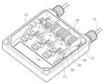
도 1은 본 발명에 의한 태양전지 모듈용 정션박스의 분해 사시도.
도 2는 본 발명의 태양전지 모듈용 정션박스의 외관 사시도.
도 3은 본 발명의 태양전지 모듈용 정션박스의 내부 사시도.
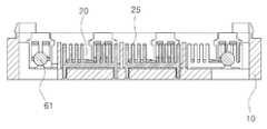
도 4는 본 발명의 요부구성인 히트 싱크 설치부 단면도.
도 5는 본 발명의 요부구성인 다이오드 연결부 사시도.
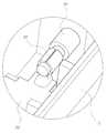
도 6은 본 발명의 요부구성인 케이블 와이어 연결부 사시도.
도 7은 본 발명의 요부구성인 리본 와이어 체결부의 일 실시예의 작동도.
도 8은 본 발명의 요부구성인 리본 와이어 체결부의 다른 실시예의 작동도.
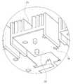
도 9는 본 발명의 요부구성인 히트 싱크 설치부의 저면 사시도.
도 10은 본 발명의 요부구성인 터미널과 주변 구성이 도시된 평면도.
도 11은 본 발명의 요부구성인 제습수단이 도시된 구성도.
도 12는 본 발명의 요부구성인 다이오드 및 히트 싱크의 다른 설치 예가 도시된 참고도.
도 13은 본 발명의 요부구성인 절연 열확산 부재가 도시된 참고도.1 is an exploded perspective view of a junction box for a solar cell module according to the present invention.
Figure 2 is an external perspective view of the junction box for a solar cell module of the present invention.
Figure 3 is an internal perspective view of the junction box for a solar cell module of the present invention.
Figure 4 is a cross-sectional view of the heat sink installation portion of the main component of the present invention.
Figure 5 is a perspective view of the diode connection of the main component of the present invention.
Figure 6 is a perspective view of the cable wire connection that is the main component of the present invention.
Figure 7 is an operation of one embodiment of the ribbon wire fastening portion of the main component of the present invention.
Figure 8 is an operation of another embodiment of the ribbon wire fastening portion of the main component of the present invention.
9 is a bottom perspective view of a heat sink mounting portion that is a main component of the present invention.
10 is a plan view showing the terminal and the peripheral configuration, which is a main component of the present invention.
11 is a block diagram showing a dehumidifying means that is a main component of the present invention.
Fig. 12 is a reference diagram showing another example of installation of a diode and a heat sink which are main components of the present invention.
Fig. 13 is a reference diagram showing an insulating thermal diffusion member which is a main component of the present invention.
이하, 첨부된 도면을 참조하여 본 발명의 태양전지 모듈용 정션박스를 설명하면 다음과 같다.Hereinafter, a junction box for a solar cell module of the present invention will be described with reference to the accompanying drawings.
본 발명의 태양전지 모듈용 정션박스는, 복수의 태양전지(도시 생략)에 각각 연결된 복수개의 터미널(Terminal, 30)과; 상기 터미널(30)과 일체형으로 이루어진하우징(Housing, 10)과; 상기 하우징(10)의 상부에서 개스킷(Gasket, 55)을 개재하여 결합되어 내부를 보호하는 커버(Cover, 50)와; 상기 하우징(10)의 폭 방향으로 이격되게 위치한 터미널(30)에 각각 연결된 한 쌍의 케이블(Cable) 부재(60)와; 상기 터미널(30) 사이의 연결부에 각각 설치되어 손상된 태양전지를 바이패스(Bypass)하여 전류를 전달하는 판 형상의 다이오드(Diode, 20)와; 상기 다이오드(20)의 후방에 각각 설치되어 상기 다이오드(20)에서 발생하는 열을 방출하는 히트 싱크(Heat Sink, 25)와; 상기 커버(50) 또는 하우징의 측벽에 설치되어 상기 하우징(10) 내부에서 발생하는 열과 습기를 외부로 방출하는 방수제습수단(40);을 포함하여 이루어진다.The junction box for a solar cell module of the present invention includes: a plurality of terminals (Terminal) 30 respectively connected to a plurality of solar cells (not shown); A housing (10) integrally formed with the terminal (30); A cover (Cover) 50 coupled to the upper portion of the
여기서, 상기 다이오드(20)는 상기 하우징(10)에 스크류(Screw, 23)로 체결되어 고정되고, 상기 히트 싱크(25)는 상기 터미널(30)의 후방 상면에 스크류(26)로 체결되어 고정된다. 이때 상기 히트 싱크(25) 사이에는 격벽(11)이 형성될 수 있다.Here, the
한편, 상기 히트 싱크(25)를 설치하는 대신 상기 히트 싱크(25)가 설치될 위치에 절연 열확산 부재(29)를 설치할 수도 있다. 상기 열확산 부재(29)는, 절연 열확산 물질(29a) 단독으로 이루어지거나, 절연 열확산 물질(29a)을 절연 열확산 패드(Pad)(29b)로 감싸서 형성될 수 있다.Meanwhile, instead of installing the
상기 절연 열확산 부재(29)는 상기한 복수개의 터미널(30)의 후반부 상면 또는 저면에 설치되는 것이 바람직하다. 상기 열확산 부재(29)는, 상기 복수개의 터미널(30) 후단부를 일정 폭 및 두께로 연결하여, 각각의 다이오드(25)에서 발생한 열을 상기 복수개의 터미널(30)이 발산하도록 한다. 상기 절연 열확산 물질(29a)은 절연피막을 입힌 금속판재로서, 은(Ag)판이나 동(Cu)판 또는 알루미늄(Al)판이 사용될 수 있다.The insulating
한편, 상기 히트 싱크(25)는 상기 다이오드(20)의 일부를 덮은 상태로 상기 터미널(30)의 상면에 설치될 수 있다. 또한, 상기 터미널(30)의 상면에 설치된 상기 히트 싱크(25)의 상부에 상기 다이오드(20)를 위치시킬 수도 있다. 이 경우, 상기 터미널(30)과 상기 다이오드(20) 및 히트 싱크(25) 사이에 열전달용 패드(27)가 부착되거나 열전달용 그리스(Grease)가 도포되는 것이 바람직하다.The
상기 방수제습수단(40)은, 투습방수 소재로 형성된 멤브레인(Membrane, 41)과; 상기 커버(50)의 상부 또는 저부에 형성된 설치부(51) 또는 상기 하우징(10)의 측벽에 씰(Seal) 부재(42)를 개재하여 결합됨으로써 상기 멤브레인(41)을 지지하는 홀더(43)로 이루어진다. 상기 멤브레인(41)은, 상기 커버(50)의 상부 또는 저부에 형성된 설치부(51), 또는 상기 하우징(10)의 측벽에 열융착이나 스폿 웰딩에 의해 결합될 수 있다.The waterproof dehumidifying means 40, the membrane (Membrane, 41) formed of a moisture-permeable waterproof material;
상기 하우징(10) 내부에서 발생한 습기는 상기 멤브레인(41)을 통해 방출되어 상기 하우징(10) 내부가 항상 건조된 상태를 유지하게 된다.Moisture generated in the
상기 케이블 부재(60)는, 터미널(30)의 후방에 형성된 삽입부(32)에 단부가 압입되는 케이블 와이어(61)와, 상기 하우징(10)의 폭 방향으로 이격되게 위치한 한 쌍의 케이블 삽입부(66)에 체결되는 와이어 너트(62)와, 상기 케이블 삽입부(66)와 상기 와이어 너트(62) 사이에 개재되는 와이어 씰(63)과, 상기 케이블 삽입부(66)에 설치되어 상기 와이어 씰(63)을 지지하는 와이어 씰 홀더(65)를 포함한다. 상기 케이블 와이어(61)의 다른 쪽 단부에는 커넥터(64)가 구비되어 있다. The
상기 케이블 와이어(61)는 상기 터미널(30)의 후방에 형성된 삽입부(32)에 삽입되며, 상기 삽입부(32)는 상기 케이블 와이어(61)의 단부를 감싼 상태로 압착되어 상기 와이어(61)를 고정한다.The
이는 종래와 같이 케이블 와이어의 단부를 클립 스프링(Clip Spring)에 삽입하여 고정할 때 발생하는 접촉 불안정 문제를 해소하기 위한 것이다. 본 발명과 같이 상기 케이블 와이어(61)와 터미널(30)을 직접 연결하게 되면, 전압강하 문제가 해소되어 품질이 향상되고 클립 스프링을 형성할 필요가 없어 제조공정이 단순화된다.This is to solve the problem of contact instability caused when inserting and fixing the end of the cable wire to the clip spring as in the prior art. When the
종래에는 상기 케이블 와이어의 단부를 클립 스프링에 단순히 삽입하여 조립함에 따라, 접촉이 불완전하고 습기나 진동 및 녹 또는 산화 등으로 인해 접촉불량이 발생하여 전압이 강하하는 등 전압 불안정에 따른 품질 저하 문제가 발생하였다.Conventionally, as the end of the cable wire is simply inserted into the clip spring and assembled, the contact is incomplete, and poor contact occurs due to moisture, vibration, rust, or oxidation, resulting in a problem of quality deterioration due to voltage instability. Occurred.
한편, 상기 다이오드(20)는 전방으로 돌출되어 양측 터미널(30)에 각각 연결되는 2개의 연결핀(21)을 구비하고, 상기 터미널(30)의 일측에서 상향 절곡된 연결편(33)의 홈에 상기 연결핀(21)이 압입된 후 스폿 웰딩(Spot Welding)되거나 납땜이 된다.On the other hand, the
이에 따라, 상기 터미널(30)과 상기 다이오드(20)의 접촉 성능이 강화된다. 종래에는 장구형 다이오드의 양측 돌기를 터미널에 구비된 클립 스프링에 압입시켜 고정하였기 때문에, 접촉 상태가 불완전하여 접촉 성능이 저하되는 문제가 있었다.Accordingly, the contact performance of the terminal 30 and the
그리고, 상기 터미널(30)은 상기 태양전지의 리본 와이어(Ribbon Wire,도시 생략)가 연결되는 선단부(31)에 돌출 형성된 복수의 엠보싱(31')을 구비한다. 상기 엠보싱(31')에 접촉되는 콘택트 스프링(Contact Spring, 12)이 장착된 스프링 홀더(13)는, 상기 하우징(10)에 구비된 힌지축(15)에 회전 가능하게 결합되어 상기 하우징(10)의 일측에 구비된 고정부재(14)에 록킹(Locking)된다. 이에 따라, 상기 엠보싱(31')과 콘택트 스프링(12) 사이에 개재되는 상기 리본 와이어(도시 생략)를 고정한다.In addition, the terminal 30 includes a plurality of embossing 31 ′ protruding from a
이를 위하여 상기 스프링 홀더(13)의 측부에는, 상기 고정부재(14)의 록킹홈(14')에 삽입 고정되는 삽입 돌기(13')가 구비된다.To this end, the side of the
따라서, 콘택트 스프링의 탄성만을 이용하여 리본 와이어를 고정하는 종래에 비해 상기 터미널(30)과 리본 와이어 사이의 접촉력을 현저하게 향상시킬 수가 있다.Therefore, the contact force between the terminal 30 and the ribbon wire can be remarkably improved as compared with the conventional method of fixing the ribbon wire using only the elasticity of the contact spring.
상기 리본 와이어가 연결되는 선단부(31)에는 리본 와이어와의 접촉저항을 감소시키기 위하여 은 또는 주석으로 도금된 도금부를 형성하는 것이 바람직하다. 상기 도금부는 복수의 엠보싱(31')을 포함하는 폭으로 형성될 수 있다.It is preferable to form a plated portion plated with silver or tin in the
또한, 상기 도금부에 금(Au)도금을 추가하여 주석도금이나 은도금에 의해 발생하는 녹 및 산화현상을 방지함으로써 제품의 내구성을 현저하게 향상시킬 수 있다.In addition, by adding gold (Au) plating to the plating portion to prevent rust and oxidation caused by tin plating or silver plating it can significantly improve the durability of the product.
또한, 리본 와이어 체결부의 다른 실시예로서, 도 8에 도시된 바와 같이, 클립(35)을 포함하는 고정부재를 사용하여 리본 와이어를 고정할 수도 있다.In addition, as another embodiment of the ribbon wire fastening portion, as shown in FIG. 8, the ribbon wire may be fixed using a fixing member including the
상기 클립(35)은, 일측에 고정부재의 조립구멍(38)에 회전 가능하게 조립되는 클립돌기(36)와, 상기 고정부재에 형성된 클립록킹부(34)에 록킹되는 클립후크(37)로 이루어진다.The
상기 터미널(30)의 선단부(31)에 리본 와이어를 올려 놓고 상기 클립(35)을 회전시켜 클립록킹부(34)에 록킹시키면, 상기 리본 와이어를 용이하게 고정할 수가 있다.When the ribbon wire is placed on the
또한, 상기 하우징(10)은, 상기 히트 싱크(25)가 설치되는 부분의 저면이 개방되어 상기 터미널(30)의 후방 및 히트 싱크(25)가 외부로 노출되도록 한다. 또한, 상기 터미널(30)에는 다수의 방열구(34)가 형성된다. 따라서, 상기 히트 싱크(25)의 방열 효율이 향상됨과 아울러 상기 터미널(30)에서 발생하는 열도 빠르게 방출될 수 있다.In addition, the
이하, 상기와 같이 구성되는 본 발명의 태양전지 모듈용 정션박스의 조립과정을 설명한다.Hereinafter, the assembly process of the junction box for a solar cell module of the present invention configured as described above.
하우징(10)에 일정 간격으로 복수개의 터미널(30)을 위치시킨 후, 상기 터미널(30) 사이의 연결부에 각각 다이오드(20)를 설치한다. 이때, 상기 다이오드(20)의 2개의 연결핀(21)을 각각 다른 터미널(30)의 연결편(33)에 결합시킨다.After the plurality of
상기 다이오드(20)는 상기 터미널(30) 사이의 연결부에 설치된다. 각 다이오드(20)에 대응하는 히트 싱크(25)는 상기 터미널(30)의 후방에 각각 설치하여, 상기 다이오드(20)에서 발생하는 열을 방출하도록 한다.The
만일 상기 다이오드(20)에서 발생하는 열을 방출하기 위하여 히트 싱크(25) 대신 열확산 패드를 사용하는 경우에는, 상기한 복수개의 터미널(30)의 양끝단을 절연 열확산 물질 또는 절연 열확산 물질을 절연 열확산 패드로 감싸서 형성한 절연 열확산 부재(29)로 연결한다. 이에 따라 각각의 다이오드(25)에서 발생한 열은 상기 복수개의 터미널(30)를 통해 방출될 수 있다.If a heat diffusion pad is used instead of the
그리고, 상기 하우징(10)의 폭 방향으로 이격되게 위치한 2개의 터미널(30)에는 양(+)과 음(-)의 케이블 부재(60)를 각각 설치한다.In addition, two (30) terminals spaced apart in the width direction of the housing (10) are provided with a positive (+) and a negative (-)
상기 케이블 부재(60)는 와이어 너트(Wire Nut, 62)를 이용하여 케이블 와이어(Cable Wire, 61)를 고정한다. 즉, 케이블 와이어(61)에 와이너 너트(62), 와이어 씰(63) 및 와이어 씰 홀더(65)를 조립하고, 이를 케이블 삽입부(66)에 삽입한 후 와이어 너트(62)를 체결함으로써 케이블 홀더(61)와 터미널(30)를 연결한다.The
이렇게 케이블 삽입부(66)에 케이블 와이어(61)가 삽입된 상태에서 와이어 너트(62)를 체결하게 되면, 와이어 씰 홀더(65)에 조립된 와이어 씰(63)이 동시에 수축되면서 상기 케이블 와이어(61)를 압착시키게 된다.When the
이에 따라, 물이나 오염물질이 케이블 연결 부위에 침투하는 것을 방지할 수 있고, 굵기가 다른 케이블도 연결하여 사용할 수 있다.Accordingly, water or contaminants can be prevented from penetrating the cable connecting portion, it is also possible to connect the cable having a different thickness.
상기 케이블 와이어(61)의 단부를 상기 터미널(30)의 삽입부(32)에 삽입시킨 후 압착시키면 상기 케이블 와이어(61)와 터미널(30)의 연결이 완료된다.When the end of the
이후, 상기 터미널(30)의 선단부(31)에 태양전지의 리본 와이어를 체결한다. 즉, 상기 터미널(30)의 선단부(31)에 상기 리본 와이어를 위치시킨 상태에서, 스프링 홀더(13)를 회전시켜 고정부재(14)에 록킹시키는 것이다.Thereafter, the ribbon wire of the solar cell is fastened to the
이에 따라, 상기 스프링 홀더(13)에 구비된 콘택트 스프링(12)이 상기 리본 와이어를 개재한 상태로 상기 선단부(31)에 형성된 엠보싱(31')에 접촉하게 되어, 상기 리본 와이어가 상기 터미널(30)의 선단부(31)에 견고하게 체결된다.Accordingly, the
또한, 리본 와이어 체결부의 다른 실시예로서, 터미널(30)의 선단부(31)에 리본 와이어를 올려 놓고 클립(35)을 회전시켜 클립록킹부(34)에 록킹시킴으로써 리본 와이어를 고정할 수도 있다.In addition, as another embodiment of the ribbon wire fastening portion, the ribbon wire may be fixed by placing the ribbon wire on the
상기 태양전지와의 연결이 끝나면, 상기 하우징(10)의 상부에 개스킷(Gasket, 55)을 개재하여 커버(50)를 결합시킨다. 이때, 상기 커버(50)의 저부 일측에 형성된 설치부(51)에 방수제습수단(40)인 멤브레인(41)을 설치하여, 상기 하우징(10) 내부의 수분이 제거되도록 하고 외부로부터는 물이나 오염물질이 침투하는 것을 방지한다.When the connection with the solar cell is finished, the
상기의 과정을 통해 조립된 본 발명의 태양전지 모듈용 정션박스는, 복수개의 태양전지에서 발생한 전기를 수집하여 인버터나 배터리로 전달하게 된다.The junction box for a solar cell module of the present invention assembled through the above process collects electricity generated from a plurality of solar cells and transfers the generated electricity to an inverter or a battery.
태양전지에서 발생한 전기는 터미널(30)과 케이블 부재(60)를 거쳐 배터리에 저장되거나 인버터에 연결되고, 태양전지, 정션박스, 케이블 부재(61), 태양전지, 정션박스, 케이블 부재(61), 태양전지에 이르는 순환회로를 형성한다.The electricity generated in the solar cell is stored in the battery or connected to the inverter via the terminal 30 and the
이때, 상기 다이오드(20)는 상기 터미널(30) 사이를 연결함과 아울러, 고장 등으로 인해 전류 흐름이 원활하지 않은 태양전지는 바이패스시켜 전류가 흐르도록 한다.In this case, the
이 과정에서 상기 다이오드(20)에 열이 발생하게 되는데, 상기 다이오드(20)에서 발생한 열은 복수개의 터미널(30) 및 그 후방에 설치된 히트 싱크(25)나 절연 열확산 물질 또는 절연 열확산 물질을 절연 열확산 패드로 감싸서 형성한 절연 열확산부재(29)를 통해 방출된다. 또한, 방수제습수단이(40)인 멤브레인(41)이 하우징 내부의 습기를 제거하게 되므로, 다이오드(20)의 열이 외부로 방출됨과 아울러 하우징(10) 내부에 열이 축적되지 않게 한다.In this process, heat is generated in the
이에 따라, 상기 다이오드(20)의 과열로 인한 성능 저하를 방지할 수 있고, 상기 다이오드(20)의 성능이 장시간 동안 유지되어 상기 다이오드(20) 및 제품의 수명을 연장할 수가 있다.Accordingly, performance degradation due to overheating of the
이상에서는 본 발명의 바람직한 실시 예를 설명하였으나, 본 발명의 범위는 이같은 특정 실시 예에만 한정되지 않으며, 해당 분야에서 통상의 지식을 가진 자라면 본 발명의 특허청구범위 내에 기재된 범주 내에서 적절하게 변경이 가능할 것이다.Although the preferred embodiments of the present invention have been described above, the scope of the present invention is not limited to such specific embodiments, and those skilled in the art may appropriately change within the scope described in the claims of the present invention. This will be possible.
10: 하우징(Housing) 11: 격벽
12: 콘택트 스프링(Contact Spring) 13: 스프링 홀더(Spring Holder)
14: 고정부재 15: 힌지(Hinge)축
20: 다이오드(Diode) 21: 연결핀(Pin)
25: 히트 싱크(Heat Sink) 27: 방열용 밴드(Band)
29: 절연 열확산 부재 30: 터미널(Terminal)
31: 선단부 32: 삽입부
33: 연결편 34: 클립록킹부
35: 클립(Clip) 36: 클립돌기
37: 클립후크 38: 조립구멍
40: 제습수단 41: 멤브레인(Membrane)
42: 씰(Seal) 부재 43: 홀더(Holder)
50: 커버(Cover) 55: 개스킷(Gasket)
60: 케이블 부재 61: 케이블 와이어(Cable Wire)
62: 와이어 너트(Wire Nut) 63: 와이어 씰(Wire Seal)
64: 커넥터(Connector)
65: 와이어 씰 홀더 (Wire Seal Holder)
66: 케이블삽입부10: Housing 11: bulkhead
12: Contact Spring 13: Spring Holder
14: fixing member 15: hinge shaft
20: Diode 21: Pin
25: Heat Sink 27: Heat Dissipation Band
29: insulation thermal diffusion member 30: terminal
31: Tip portion 32: Insertion portion
33: connecting piece 34: clip locking part
35: Clip 36: Clipping
37: Clip hook 38: Assembly hole
40: dehumidification means 41: membrane
42: seal member 43: holder
50: Cover 55: Gasket
60: cable member 61: cable wire
62: Wire Nut 63: Wire Seal
64: Connector
65: wire seal holder
66: cable insertion
Claims (14)
Translated fromKorean상기 다이오드(20)의 후방에 각각 설치되어 상기 다이오드(20)에서 발생하는 열을 방출하는 히트 싱크(25) 또는 절연 열확산 물질(29a) 단독으로 이루어지거나 상기 절연 열확산 물질(29a)을 절연 열확산 패드(Pad)(29b)로 감싸서 형성한 열확산 부재(29);를 포함하고,
투습방수 소재로 형성된 멤브레인(41)과; 상기 커버(50)의 상부 또는 저부에 형성된 설치부(51) 또는 상기 하우징(10)의 측벽에 씰(Seal) 부재(42)를 개재하여 결합됨으로써 상기 멤브레인(41)을 지지하는 홀더(43);를 포함하여 구성되어 상기 커버(50) 또는 상기 하우징(10)의 측벽에 설치되어 상기 하우징(10) 내부에서 발생하는 열과 습기를 외부로 방출하는 방수제습수단(40)을 더 구비하며,
상기 터미널(30)은,
상기 태양전지의 리본 와이어가 연결되는 선단부(31)에 클립(35)을 포함하는 고정부재를 구비하고, 상기 클립(35)의 일측에 형성된 클립돌기(36)가 상기 고정부재의 일측에 형성된 조립구멍(38)에 회전 가능하게 결합되어, 상기 클립(35)의 선단에 형성된 클립후크(37)가 상기 고정부재에 형성된 클립록킹부(34)에 록킹됨으로써, 상기 터미널(30)의 선단부(31)와 클립(35) 사이에 개재된 상기 리본 와이어를 고정하도록 한 것을 특징으로 하는 태양전지 모듈용 정션박스.A plurality of terminals 30 respectively connected to the plurality of solar cells; A housing 10 integrally formed with the terminal 30; A cover 50 coupled to an upper portion of the housing 10 to protect the inside thereof; A pair of cable members 60 connected to terminals 30 spaced apart from each other in the width direction of the housing 10; In the junction box for a solar cell module comprising a plate-shaped diode 20 is installed in each of the connection portion between the terminals 30 to bypass the damaged solar cell to transfer the current,
Each of the heat sink 25 or the insulating thermal diffusion material 29a which is installed at the rear of the diode 20 to emit heat generated by the diode 20, or the insulating thermal diffusion material 29a is insulated from each other. And a thermal diffusion member 29 formed by wrapping the pad 29b.
A membrane 41 formed of a moisture-permeable waterproof material; Holder 43 for supporting the membrane 41 by being coupled to the mounting portion 51 formed on the top or bottom of the cover 50 or the side wall of the housing 10 via a seal member 42. And a waterproof dehumidifying means 40 installed on the side wall of the cover 50 or the housing 10 to release heat and moisture generated in the housing 10 to the outside.
The terminal 30,
An assembly having a fixing member including a clip 35 on the front end portion 31 to which the ribbon wire of the solar cell is connected, the clip projection 36 formed on one side of the clip 35 is formed on one side of the fixing member The clip hook 37 rotatably coupled to the hole 38 and formed at the tip of the clip 35 is locked to the clip locking portion 34 formed on the fixing member, thereby leading to the tip 31 of the terminal 30. ) And a junction box for a solar cell module, characterized in that to fix the ribbon wire interposed between the clip (35).
상기 다이오드(20)는, 상기 하우징(10)에 납땜 또는 스크류(23)로 체결되어 고정되고,
상기 히트 싱크(25)는, 상기 터미널(30)의 후방에 스크류(26)로 체결되어 고정됨과 아울러, 상기 히트 싱크(25) 사이에는 각각 격벽(11)이 돌출 형성된 것을 특징으로 하는 태양전지 모듈용 정션박스.The method of claim 1,
The diode 20 is fixed to the housing 10 by fastening with a solder or screw 23,
The heat sink 25 is fixed to the rear of the terminal 30 by a screw 26 and fixed, and the partition 11 is formed between the heat sink 25, the solar cell module, characterized in that Junction box.
상기 열확산 부재(29)는, 상기한 복수개의 터미널(30)의 후단부 상면 또는 저면에 설치되며, 상기 복수개의 터미널(30) 후단부를 일정 폭 및 두께로 연결하여, 각각의 다이오드(25)에서 발생하는 열을 상기 복수개의 터미널(30)이 발산하도록 하는 것을 특징으로 하는 태양전지 모듈용 정션박스.The method of claim 1,
The thermal diffusion member 29 is installed on the top or bottom surface of the rear end of the plurality of terminals 30, and connects the rear ends of the plurality of terminals 30 to a predetermined width and thickness, respectively, in each diode 25. Junction box for a solar cell module, characterized in that the plurality of terminals 30 to dissipate the generated heat.
상기 방수제습수단(40)은, 투습방수 소재로 형성된 멤브레인을 상기 커버(50)의 상부 또는 저부에 형성된 설치부(51) 또는 상기 하우징(10)의 측벽에 열융착이나 스폿 웰딩으로 결합시켜 형성하는 것을 특징으로 하는 태양전지 모듈용 정션박스.The method of claim 1,
The waterproof dehumidifying means 40 is formed by coupling the membrane formed of the moisture-permeable waterproof material to the installation portion 51 formed on the upper or lower portion of the cover 50 or the side wall of the housing 10 by heat fusion or spot welding. Junction box for a solar cell module, characterized in that.
상기 케이블 부재(60)의 케이블 와이어(61)는 상기 터미널(30)의 후방에 형성된 삽입부(32)에 삽입되며, 상기 삽입부(32)는 상기 케이블 와이어(61)의 단부를 감싼 상태로 압착되어 상기 케이블 와이어(61)를 고정하는 것을 특징으로 하는 태양전지 모듈용 정션박스.The method of claim 1,
The cable wire 61 of the cable member 60 is inserted into the insertion portion 32 formed at the rear of the terminal 30, the insertion portion 32 is wrapped in the end of the cable wire 61 The junction box for a solar cell module, characterized in that the crimped to fix the cable wire (61).
상기 다이오드(20)는 전방으로 돌출되어 양측 터미널(30)에 각각 연결되는 2개의 연결핀(21)을 구비하고, 상기 터미널(30)의 일측에서 상향 절곡된 연결편(33)의 홈에 상기 연결핀(21)이 압입된 후 스폿 웰딩 또는 납땜하여 서로 연결시킨 것을 특징으로 하는 태양전지 모듈용 정션박스.The method of claim 1,
The diode 20 has two connecting pins 21 which protrude forward and are connected to both terminals 30, respectively, and are connected to the grooves of the connecting pieces 33 which are bent upward from one side of the terminal 30. Junction box for a solar cell module, characterized in that the pin 21 is pressed and then connected by spot welding or soldering.
상기 터미널(30)은, 상기 태양전지의 리본 와이어가 연결되는 선단부(31)에 돌출 형성된 복수의 엠보싱(31')을 구비하고,
상기 엠보싱(31')에 접촉되는 콘택트 스프링(12)이 장착된 스프링 홀더(13)가, 상기 하우징(10)에 구비된 힌지축(15)에 회전 가능하게 결합되어 상기 하우징(10)의 일측에 구비된 고정부재(14)에 록킹됨으로써, 상기 엠보싱(31')와 콘택트 스프링(12) 사이에 개재된 상기 리본 와이어를 고정하도록 한 것을 특징으로 하는 태양전지 모듈용 정션박스.The method of claim 1,
The terminal 30 has a plurality of embossing 31 'protruding from the tip portion 31 to which the ribbon wire of the solar cell is connected,
A spring holder 13 equipped with a contact spring 12 in contact with the embossing 31 ′ is rotatably coupled to a hinge shaft 15 provided in the housing 10 so that one side of the housing 10 is provided. Locking to the fixing member 14 provided in the, junction box for a solar cell module, characterized in that to fix the ribbon wire interposed between the embossing (31 ') and the contact spring (12).
상기 터미널(30)은, 리본 와이어와의 접촉저항이 감소되도록 상기 리본 와이어가 연결되는 선단부(31)에 은 또는 주석이 도금되어 형성된 도금부를 포함하고,
상기 도금부는 상기한 복수의 엠보싱(31')을 포함하는 폭으로 형성되는 것을 특징으로 하는 태양전지 모듈용 정션박스.The method of claim 8,
The terminal 30 includes a plated portion formed by plating silver or tin on the tip portion 31 to which the ribbon wire is connected so as to reduce contact resistance with the ribbon wire.
The plating unit junction box for a solar cell module, characterized in that formed in a width including the plurality of embossing (31 ').
상기 터미널(30)은, 리본 와이어와의 접촉부에 녹이나 산화 현상이 발생하지 않도록 상기 도금부에 금(Au)이 도금된 것을 특징으로 하는 태양전지 모듈용 정션박스.10. The method of claim 9,
The terminal 30, the junction box for a solar cell module, characterized in that gold (Au) is plated in the plating portion so that rust or oxidation does not occur in the contact portion with the ribbon wire.
상기 하우징(10)은 상기 히트 싱크(25)가 설치되는 부분의 저면이 개방되어 상기 터미널(30)의 후방 및 히트 싱크(25)가 외부로 노출되도록 함과 아울러, 상기 터미널(30)에 다수의 방열구(34)가 형성된 것을 특징으로 하는 태양전지 모듈용 정션박스.The method of claim 1,
The housing 10 has a bottom surface of the portion where the heat sink 25 is installed to open so that the rear of the terminal 30 and the heat sink 25 are exposed to the outside, and the plurality of the terminal 30 Junction box for a solar cell module, characterized in that the heat dissipation hole 34 is formed.
상기 터미널(30)과 상기 다이오드(20) 및 히트 싱크(25) 사이에 열전달용 패드(27)가 부착되거나 열전달용 그리스가 도포된 것을 특징으로 하는 태양전지 모듈용 정션박스.The method of claim 1,
Junction box for a solar cell module, characterized in that the heat transfer pad 27 is attached or heat grease is applied between the terminal 30 and the diode 20 and the heat sink 25.
상기 케이블 부재(60)는, 상기 터미널(30)의 후방에 형성된 삽입부(32)에 단부가 압입되는 케이블 와이어(61)와, 상기 하우징(10)의 폭 방향으로 이격되게 위치한 한 쌍의 케이블 삽입부(66)에 체결되는 와이어 너트(62)와, 상기 케이블 삽입부(66)와 상기 와이어 너트(62) 사이에 개재되는 와이어 씰(63)과, 상기 케이블 삽입부(66)에 설치되어 상기 와이어 씰(63)을 지지하는 와이어 씰 홀더(65)를 포함하고,
상기 케이블 삽입부(66)에 상기 케이블 와이어(61)가 삽입된 상태에서 상기 와이어 너트(62)를 체결할 때, 상기 와이어 씰 홀더(65)에 조립된 와이어 씰(63)이 동시에 수축되면서 상기 케이블 와이어(61)를 압착하도록 한 것을 특징으로 하는 태양전지 모듈용 정션박스.The method of claim 1,
The cable member 60 may include a cable wire 61 having an end portion pressed into an insertion portion 32 formed at the rear of the terminal 30, and a pair of cables spaced apart in the width direction of the housing 10. A wire nut 62 fastened to the insertion portion 66, a wire seal 63 interposed between the cable insertion portion 66 and the wire nut 62, and the cable insertion portion 66. A wire seal holder 65 supporting the wire seal 63;
When the wire nut 62 is fastened in the state in which the cable wire 61 is inserted into the cable insertion part 66, the wire seal 63 assembled to the wire seal holder 65 is simultaneously contracted. Junction box for solar cell module, characterized in that the cable wire 61 to be crimped.
Priority Applications (3)
| Application Number | Priority Date | Filing Date | Title |
|---|---|---|---|
| PCT/KR2010/006155WO2011111915A2 (en) | 2010-03-11 | 2010-09-10 | Junction box for solar cell module |
| US13/634,233US20130003307A1 (en) | 2010-03-11 | 2010-09-10 | Solar cell module junction box |
| EP10847549.2AEP2546888A4 (en) | 2010-03-11 | 2010-09-10 | Junction box for solar cell module |
Applications Claiming Priority (2)
| Application Number | Priority Date | Filing Date | Title |
|---|---|---|---|
| KR20090087896 | 2009-09-17 | ||
| KR1020090087896 | 2009-09-17 |
Publications (1)
| Publication Number | Publication Date |
|---|---|
| KR100981362B1true KR100981362B1 (en) | 2010-09-10 |
Family
ID=43009952
Family Applications (1)
| Application Number | Title | Priority Date | Filing Date |
|---|---|---|---|
| KR1020100021758AExpired - Fee RelatedKR100981362B1 (en) | 2009-09-17 | 2010-03-11 | Junction box for solar cell module |
Country Status (1)
| Country | Link |
|---|---|
| KR (1) | KR100981362B1 (en) |
Cited By (15)
| Publication number | Priority date | Publication date | Assignee | Title |
|---|---|---|---|---|
| KR101016376B1 (en) | 2010-10-12 | 2011-02-18 | 주식회사 넥센테크 | Solar module connection device |
| KR101182580B1 (en) | 2011-01-24 | 2012-09-18 | 주식회사 솔라파크코리아 | Junction box and solar battery module having the same |
| KR101185438B1 (en) | 2011-03-14 | 2012-10-02 | 동아전장주식회사 | Junction box |
| KR101220438B1 (en) | 2011-11-18 | 2013-01-21 | 주식회사 엘스콤 | Terminal rail of junction box for a photovoltaic module |
| KR101228041B1 (en) | 2011-03-14 | 2013-02-19 | 동아전장주식회사 | Junction box |
| CN102983191A (en)* | 2011-09-05 | 2013-03-20 | 新浦莱斯有限公司 | Junction box used for solar cell module |
| KR101272096B1 (en) | 2012-03-08 | 2013-06-07 | 주식회사엘디티 | Smart junction box for malfunction detection of photovoltaic module |
| KR101286197B1 (en) | 2013-04-04 | 2013-07-15 | 박일순 | Junction box for solar power generation |
| KR200468714Y1 (en) | 2012-04-10 | 2013-09-02 | 한맥전자 (주) | Junction box for preventing inside heat generation |
| KR101354507B1 (en)* | 2012-02-23 | 2014-01-27 | 김영춘 | Junction box for solar battery module |
| KR101636914B1 (en)* | 2015-06-26 | 2016-07-06 | 임명수 | Heating panel assembly of modularizing diode for solar light generation |
| KR101696326B1 (en)* | 2016-07-29 | 2017-01-17 | 주식회사 강경씨엔에스 | Ships junction box |
| CN110677123A (en)* | 2019-11-13 | 2020-01-10 | 江苏海天微电子股份有限公司 | A new type of photovoltaic junction box |
| KR20230075650A (en) | 2021-11-23 | 2023-05-31 | 신선숙 | Junction box for high-efficiency ultra-small bifacial photovoltaic module |
| CN119209044A (en)* | 2024-11-28 | 2024-12-27 | 华能陇东能源有限责任公司 | A solar photovoltaic cable installation device |
Citations (4)
| Publication number | Priority date | Publication date | Assignee | Title |
|---|---|---|---|---|
| JP2006073978A (en)* | 2004-05-07 | 2006-03-16 | Sumitomo Wiring Syst Ltd | Terminal box for solar cell module and rectifier cell unit |
| JP2007109993A (en) | 2005-10-17 | 2007-04-26 | Furukawa Electric Co Ltd:The | Circuit board built-in housing |
| KR100884815B1 (en) | 2008-11-18 | 2009-02-20 | 주식회사 엘스콤 | Terminal box for solar cell module |
| JP2009302590A (en) | 2004-05-07 | 2009-12-24 | Sumitomo Wiring Syst Ltd | Terminal box for solar-battery module |
- 2010
- 2010-03-11KRKR1020100021758Apatent/KR100981362B1/ennot_activeExpired - Fee Related
Patent Citations (4)
| Publication number | Priority date | Publication date | Assignee | Title |
|---|---|---|---|---|
| JP2006073978A (en)* | 2004-05-07 | 2006-03-16 | Sumitomo Wiring Syst Ltd | Terminal box for solar cell module and rectifier cell unit |
| JP2009302590A (en) | 2004-05-07 | 2009-12-24 | Sumitomo Wiring Syst Ltd | Terminal box for solar-battery module |
| JP2007109993A (en) | 2005-10-17 | 2007-04-26 | Furukawa Electric Co Ltd:The | Circuit board built-in housing |
| KR100884815B1 (en) | 2008-11-18 | 2009-02-20 | 주식회사 엘스콤 | Terminal box for solar cell module |
Cited By (17)
| Publication number | Priority date | Publication date | Assignee | Title |
|---|---|---|---|---|
| WO2012050297A1 (en)* | 2010-10-12 | 2012-04-19 | 주식회사 넥센테크 | Device for connecting photovoltaic module |
| KR101016376B1 (en) | 2010-10-12 | 2011-02-18 | 주식회사 넥센테크 | Solar module connection device |
| KR101182580B1 (en) | 2011-01-24 | 2012-09-18 | 주식회사 솔라파크코리아 | Junction box and solar battery module having the same |
| KR101185438B1 (en) | 2011-03-14 | 2012-10-02 | 동아전장주식회사 | Junction box |
| KR101228041B1 (en) | 2011-03-14 | 2013-02-19 | 동아전장주식회사 | Junction box |
| CN102983191B (en)* | 2011-09-05 | 2015-07-29 | 新浦莱斯有限公司 | Solar module terminal box |
| CN102983191A (en)* | 2011-09-05 | 2013-03-20 | 新浦莱斯有限公司 | Junction box used for solar cell module |
| KR101220438B1 (en) | 2011-11-18 | 2013-01-21 | 주식회사 엘스콤 | Terminal rail of junction box for a photovoltaic module |
| KR101354507B1 (en)* | 2012-02-23 | 2014-01-27 | 김영춘 | Junction box for solar battery module |
| KR101272096B1 (en) | 2012-03-08 | 2013-06-07 | 주식회사엘디티 | Smart junction box for malfunction detection of photovoltaic module |
| KR200468714Y1 (en) | 2012-04-10 | 2013-09-02 | 한맥전자 (주) | Junction box for preventing inside heat generation |
| KR101286197B1 (en) | 2013-04-04 | 2013-07-15 | 박일순 | Junction box for solar power generation |
| KR101636914B1 (en)* | 2015-06-26 | 2016-07-06 | 임명수 | Heating panel assembly of modularizing diode for solar light generation |
| KR101696326B1 (en)* | 2016-07-29 | 2017-01-17 | 주식회사 강경씨엔에스 | Ships junction box |
| CN110677123A (en)* | 2019-11-13 | 2020-01-10 | 江苏海天微电子股份有限公司 | A new type of photovoltaic junction box |
| KR20230075650A (en) | 2021-11-23 | 2023-05-31 | 신선숙 | Junction box for high-efficiency ultra-small bifacial photovoltaic module |
| CN119209044A (en)* | 2024-11-28 | 2024-12-27 | 华能陇东能源有限责任公司 | A solar photovoltaic cable installation device |
Similar Documents
| Publication | Publication Date | Title |
|---|---|---|
| KR100981362B1 (en) | Junction box for solar cell module | |
| WO2011111915A2 (en) | Junction box for solar cell module | |
| US8512050B2 (en) | Solar panel junction box | |
| US6655987B2 (en) | Terminal box apparatus for solar cell module | |
| JP4854081B2 (en) | Connection device, manufacturing method thereof and solar module | |
| JP3744531B1 (en) | Terminal box for solar cell module and rectifying element unit | |
| JP3852711B1 (en) | Terminal box for solar cell module | |
| WO2007052407A1 (en) | Terminal box for solar battery module | |
| US7369398B2 (en) | Terminal box and a method of providing it | |
| EP2279529A2 (en) | Solar panel junction box | |
| JP2010524244A (en) | Connection box | |
| JP2001168368A (en) | Terminal box | |
| JP5393783B2 (en) | Terminal box for solar cell module | |
| US20160240711A1 (en) | Diode cell modules | |
| JP5131562B2 (en) | Terminal box for solar cell module | |
| ES2380614T3 (en) | Electrical connection device for conductive contacts, in particular blade contacts | |
| JP3573328B2 (en) | Heat dissipation structure of electrical junction box | |
| US20090239138A1 (en) | Multiple-cell battery | |
| JPWO2016181525A1 (en) | Solar cell module and method for manufacturing solar cell module | |
| FR2839607A1 (en) | ASSEMBLY OF POWER COMPONENTS ON A PRINTED CIRCUIT AS WELL AS A METHOD FOR OBTAINING SUCH A ASSEMBLY | |
| JP2013522870A (en) | Solar cell module connection box | |
| JP5622419B2 (en) | Terminal box for solar cell module | |
| JP4412225B2 (en) | Terminal box for solar cell module | |
| JP3744530B1 (en) | Terminal box for solar cell module | |
| JP2006351597A (en) | Terminal box for solar cell module |
Legal Events
| Date | Code | Title | Description |
|---|---|---|---|
| A201 | Request for examination | ||
| PA0109 | Patent application | St.27 status event code:A-0-1-A10-A12-nap-PA0109 | |
| PA0201 | Request for examination | St.27 status event code:A-1-2-D10-D11-exm-PA0201 | |
| A302 | Request for accelerated examination | ||
| PA0302 | Request for accelerated examination | St.27 status event code:A-1-2-D10-D17-exm-PA0302 St.27 status event code:A-1-2-D10-D16-exm-PA0302 | |
| P11-X000 | Amendment of application requested | St.27 status event code:A-2-2-P10-P11-nap-X000 | |
| P13-X000 | Application amended | St.27 status event code:A-2-2-P10-P13-nap-X000 | |
| D13-X000 | Search requested | St.27 status event code:A-1-2-D10-D13-srh-X000 | |
| D14-X000 | Search report completed | St.27 status event code:A-1-2-D10-D14-srh-X000 | |
| E902 | Notification of reason for refusal | ||
| PE0902 | Notice of grounds for rejection | St.27 status event code:A-1-2-D10-D21-exm-PE0902 | |
| E13-X000 | Pre-grant limitation requested | St.27 status event code:A-2-3-E10-E13-lim-X000 | |
| P11-X000 | Amendment of application requested | St.27 status event code:A-2-2-P10-P11-nap-X000 | |
| P13-X000 | Application amended | St.27 status event code:A-2-2-P10-P13-nap-X000 | |
| E701 | Decision to grant or registration of patent right | ||
| PE0701 | Decision of registration | St.27 status event code:A-1-2-D10-D22-exm-PE0701 | |
| GRNT | Written decision to grant | ||
| PR0701 | Registration of establishment | St.27 status event code:A-2-4-F10-F11-exm-PR0701 | |
| PR1002 | Payment of registration fee | St.27 status event code:A-2-2-U10-U11-oth-PR1002 Fee payment year number:1 | |
| PG1601 | Publication of registration | St.27 status event code:A-4-4-Q10-Q13-nap-PG1601 | |
| FPAY | Annual fee payment | Payment date:20130828 Year of fee payment:4 | |
| PR1001 | Payment of annual fee | St.27 status event code:A-4-4-U10-U11-oth-PR1001 Fee payment year number:4 | |
| P22-X000 | Classification modified | St.27 status event code:A-4-4-P10-P22-nap-X000 | |
| LAPS | Lapse due to unpaid annual fee | ||
| PC1903 | Unpaid annual fee | St.27 status event code:A-4-4-U10-U13-oth-PC1903 Not in force date:20140904 Payment event data comment text:Termination Category : DEFAULT_OF_REGISTRATION_FEE | |
| PC1903 | Unpaid annual fee | St.27 status event code:N-4-6-H10-H13-oth-PC1903 Ip right cessation event data comment text:Termination Category : DEFAULT_OF_REGISTRATION_FEE Not in force date:20140904 | |
| P22-X000 | Classification modified | St.27 status event code:A-4-4-P10-P22-nap-X000 | |
| P22-X000 | Classification modified | St.27 status event code:A-4-4-P10-P22-nap-X000 |