KR100975587B1 - Tuned Duplexer with Common Node Notch Filter - Google Patents
Tuned Duplexer with Common Node Notch FilterDownload PDFInfo
- Publication number
- KR100975587B1 KR100975587B1KR1020077025751AKR20077025751AKR100975587B1KR 100975587 B1KR100975587 B1KR 100975587B1KR 1020077025751 AKR1020077025751 AKR 1020077025751AKR 20077025751 AKR20077025751 AKR 20077025751AKR 100975587 B1KR100975587 B1KR 100975587B1
- Authority
- KR
- South Korea
- Prior art keywords
- receive
- transmit
- mobile station
- band
- frequency
- Prior art date
- Legal status (The legal status is an assumption and is not a legal conclusion. Google has not performed a legal analysis and makes no representation as to the accuracy of the status listed.)
- Expired - Fee Related
Links
Images


Classifications
- H—ELECTRICITY
- H01—ELECTRIC ELEMENTS
- H01P—WAVEGUIDES; RESONATORS, LINES, OR OTHER DEVICES OF THE WAVEGUIDE TYPE
- H01P1/00—Auxiliary devices
- H01P1/20—Frequency-selective devices, e.g. filters
- H01P1/215—Frequency-selective devices, e.g. filters using ferromagnetic material
- H01P1/217—Frequency-selective devices, e.g. filters using ferromagnetic material the ferromagnetic material acting as a tuning element in resonators
- H—ELECTRICITY
- H04—ELECTRIC COMMUNICATION TECHNIQUE
- H04B—TRANSMISSION
- H04B1/00—Details of transmission systems, not covered by a single one of groups H04B3/00 - H04B13/00; Details of transmission systems not characterised by the medium used for transmission
- H04B1/38—Transceivers, i.e. devices in which transmitter and receiver form a structural unit and in which at least one part is used for functions of transmitting and receiving
- H04B1/40—Circuits
- H04B1/50—Circuits using different frequencies for the two directions of communication
- H04B1/52—Hybrid arrangements, i.e. arrangements for transition from single-path two-direction transmission to single-direction transmission on each of two paths or vice versa
Landscapes
- Engineering & Computer Science (AREA)
- Computer Networks & Wireless Communication (AREA)
- Signal Processing (AREA)
- Mobile Radio Communication Systems (AREA)
- Transceivers (AREA)
Abstract
Translated fromKoreanDescription
Translated fromKorean본 발명은 일반적으로 무선 통신 시스템에 관한 것이고, 더욱 상세하게는, 공통 노드 노치 필터를 구비한 동조식(tunable) 듀플렉서를 제공하는 시스템 및 방법에 관한 것이다.TECHNICAL FIELD The present invention generally relates to wireless communication systems, and more particularly, to systems and methods for providing a tunable duplexer having a common node notch filter.
전-이중(full-duplex) 무선 송수신기들(transceivers)이 셀룰러 전화기와 같은 많은 이동 통신 장치에 사용된다. 이러한 송수신기는 공통 안테나를 공유하는 송신 경로와 수신 경로를 포함한다. 송신 신호의 수신 신호로의 누설(leakage) 및 수신 신호의 송신 신호로의 누설을 회피하도록 시스템들이 설계된다.Full-duplex wireless transceivers are used in many mobile communication devices such as cellular telephones. Such a transceiver includes a transmission path and a reception path sharing a common antenna. Systems are designed to avoid leakage of the transmitted signal into the received signal and leakage of the received signal into the transmitted signal.
소형 전-이중 무선 송수신기들이 많은 셀룰러 전화기들에 사용된다. 송수신기의 송신 경로와 수신 경로는 듀플렉서에 의해 안테나에 모두 결합된다. 듀플렉서는 송신 및 수신 필터링을 모두 수행한다. 듀플렉서는 송신 신호의 수신 신호로의 누설 및 수신 신호의 송신 신호로의 누설을 회피하도록 설계된다.Small full-duplex radio transceivers are used in many cellular telephones. The transmit and receive paths of the transceiver are both coupled to the antenna by a duplexer. The duplexer performs both transmit and receive filtering. The duplexer is designed to avoid leakage of the transmission signal into the reception signal and leakage of the reception signal into the transmission signal.
송신 신호와 수신 신호를 적절히 필터링하고, 송신 신호와 수신 신호를 간단한 토폴로지(topology)로 분리하는 듀플렉서를 제공하는 것이 바람직하다. 따라서 송신 및 수신 신호를 필터링하고, 송신 및 수신 신호를 분리하는 개선된 듀플렉서 를 제공함으로써 장점이 실현될 수 있다.It is desirable to provide a duplexer that properly filters the transmitted and received signals and separates the transmitted and received signals into a simple topology. Thus, the advantages can be realized by providing an improved duplexer to filter the transmitted and received signals and to separate the transmitted and received signals.
동조식 듀플렉서를 구비한 이동국(mobile station)이 개시된다. 이동국은 프로세서, 및 이 프로세서와 전기적으로 연통된(in electronic communication) 메모리를 포함한다. 안테나 또한 포함된다. 이동국은 공통 노드에서 안테나와 전기적으로 연통되며 동조식인 수신 대역 저지 필터를 구비한 수신 경로를 포함한다. 수신 경로는 수신 대역 저지 필터와 전기적으로 연통되고 동조식인 수신 대역 통과 필터를 또한 포함한다. 이동국은 공통 노드에서 안테나와 전기적으로 연통되며 동조식인 송신 대역 저지 필터를 구비한 송신 경로를 포함한다. 송신 경로는 송신 대역 저지 필터와 전기적으로 연통되고 동조식인 송신 대역 통과 필터를 또한 포함한다.A mobile station having a tuned duplexer is disclosed. The mobile station includes a processor and a memory in electronic communication with the processor. Antennas are also included. The mobile station includes a receive path having a tuned receive band rejection filter in electrical communication with the antenna at a common node. The receive path also includes a receive band pass filter in electrical communication with and tuned to the receive band reject filter. The mobile station includes a transmission path having a tuned transmission band rejection filter that is in electrical communication with the antenna at a common node. The transmit path also includes a transmit band pass filter in electrical communication with and tuned to the transmit band reject filter.
일부 실시예에서, 수신 대역 저지 필터는 송신 주파수를 저지하도록 구성된 단극(single-pole) 대역 저지 필터를 포함할 수 있다. 또한, 수신 대역 저지 필터는 0도 위상(zero degree phase)에서 1의 반사 계수(reflection coefficient)를 갖도록 구성될 수 있다. 수신 대역 통과 필터는 수신 주파수를 통과시키도록 구성된 쌍극(two-pole) 대역 통과 필터를 포함할 수 있다.In some embodiments, the receive band reject filter may comprise a single-pole band reject filter configured to block the transmit frequency. In addition, the reception band rejection filter may be configured to have a reflection coefficient of 1 in a zero degree phase. The receive band pass filter may comprise a two-pole band pass filter configured to pass the receive frequency.
송신 대역 저지 필터는 수신 주파수를 저지하도록 구성된 단극 대역 저지 필터를 포함할 수 있다. 송신 대역 저지 필터는 0도 위상에서 1의 반사 계수를 갖도록 구성될 수 있다. 송신 대역 통과 필터는 송신 주파수를 통과시키도록 구성된 쌍극 대역 통과 필터를 포함할 수 있다.The transmit band reject filter may comprise a monopole band reject filter configured to reject a receive frequency. The transmit band reject filter may be configured to have a reflection coefficient of 1 in zero degree phase. The transmit band pass filter may comprise a bipolar band pass filter configured to pass a transmission frequency.
동조식 듀플렉서를 구비한 이동국이 개시된다. 이동국은 처리 수단, 이 처리 수단과 전기적으로 연통되고 정보를 저장하는 수단을 구비한다. 무선 신호를 송수신하는 수단이 또한 구비된다.A mobile station having a tuned duplexer is disclosed. The mobile station has processing means, means for being in electrical communication with the processing means and storing information. Means are also provided for transmitting and receiving wireless signals.
이동국은 무선 신호를 송수신하는 수단과 공통 노드에서 전기적으로 연통되고 송신 주파수를 저지하는 수단을 구비한다. 송신 주파수를 저지하는 수단과 전기적으로 연통되고 수신 주파수를 통과시키는 수단이 또한 구비된다. 무선 신호를 송수신하는 수단과 공통 노드에서 전기적으로 연통되고 수신 주파수를 저지하는 수단이 구비된다. 또한, 이동국은 수신 주파수를 저지하는 수단과 전기적으로 연통되고 송신 주파수를 통과시키는 수단을 또한 구비한다.The mobile station has means for transmitting and receiving radio signals and means for electrically communicating at a common node and blocking transmission frequencies. Means are also provided which are in electrical communication with the means for blocking the transmission frequency and for passing the reception frequency. Means are provided for transmitting and receiving wireless signals and means for electrically communicating at a common node and for preventing a receive frequency. In addition, the mobile station also has means for being in electrical communication with the means for intercepting the reception frequency and for passing the transmission frequency.
무선 통신을 위해 구성된 이동국에서의 방법이 개시된다. 송신 주파수 및 수신 주파수가 얻어진다. 송신 경로상 제1 단극 대역 저지 필터가 동조되어 수신 주파수를 저지한다. 송신 경로상 제1 쌍극 대역 통과 필터가 동조되어 송신 주파수를 통과시킨다. 수신 경로상 제2 단극 대역 저지 필터가 동조되어 송신 주파수를 저지한다. 수신 경로상 제2 쌍극 대역 통과 필터가 동조되어 수신 주파수를 통과시킨다.A method in a mobile station configured for wireless communication is disclosed. The transmission frequency and the reception frequency are obtained. The first unipolar band reject filter on the transmission path is tuned to block the receive frequency. A first dipole band pass filter is tuned on the transmission path to pass the transmission frequency. A second monopole band reject filter on the receive path is tuned to block the transmit frequency. A second dipole band pass filter is tuned on the receive path to pass the receive frequency.
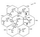
도1은 다수의 사용자를 지원하고, 본 명세서에 설명된 실시예의 적어도 일부 장점을 구현할 수 있는 통신 시스템의 일 실시예를 예시한다.1 illustrates one embodiment of a communication system that supports multiple users and may implement at least some of the advantages of the embodiments described herein.
도2는 다운링크와 업링크를 예시하는 기지국와 이동국의 블록도이다.2 is a block diagram of a base station and a mobile station illustrating the downlink and uplink.
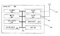
도3은 가입자 유닛의 일 실시예의 기능 블록도이다.3 is a functional block diagram of one embodiment of a subscriber unit.
도4는 이동국내 동조식 듀플렉서 시스템의 전체 블록도이다.4 is an overall block diagram of a mobile station tuned duplexer system.
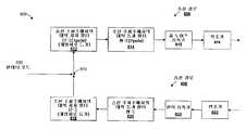
도5는 동조식 듀플렉서 시스템의 일 실시예의 더욱 상세한 블록도이다.5 is a more detailed block diagram of one embodiment of a tuned duplexer system.
도6은 이동국에서 공통 노드 노치 필터를 이용하여 듀플렉서를 동조하는 방법의 일 실시예의 흐름도이다.6 is a flow diagram of one embodiment of a method for tuning a duplexer using a common node notch filter at a mobile station.
단어 “모범적(exemplary)"은 보기, 실례, 예시로서 기능함을 의미하기 위하여 사용되었다. 모범적인 것으로 기술된 모든 실시예는 다른 실시예에 비하여 선호되거나 바람직하다는 것으로 반드시 해석되는 것은 아니다.The word “exemplary” is used to mean functioning as an example, illustration, or example. All embodiments described as exemplary are not necessarily to be construed as preferred or preferred over other embodiments.
모범적 실시예가 본 설명을 통해 제공되지만, 대안적 실시예가 본발명의 사상을 벗어나지 않고 다양한 장점을 포함할 수 있다. 특히, 일 실시예는 데이터 처리 시스템, 무선 통신 시스템, 이동 IP 네트워크 및 무선 신호를 수신하고 처리하는 임의의 다른 시스템에 적용가능하다.While exemplary embodiments are provided throughout this description, alternative embodiments may include various advantages without departing from the spirit of the invention. In particular, one embodiment is applicable to data processing systems, wireless communication systems, mobile IP networks, and any other system that receives and processes wireless signals.
무선 통신 시스템들은 넓게 배치되어 음성, 데이터 등과 같은 다양한 형태의 통신을 제공한다. 이러한 시스템은 코드 분할 다중 접속(Code Division- Multiple Access; CDMA), 시 분할 다중 접속(Time Division-Multiple Access; TDMA), 또는 다른 변조 기술들에 근거할 수 있다. CDMA 시스템은 다른 형태의 시스템에 비하여, 증가된 시스템 용량을 포함하는 소정 장점을 제공한다.Wireless communication systems are widely deployed to provide various forms of communication such as voice, data, and the like. Such a system may be based on Code Division-Multiple Access (CDMA), Time Division-Multiple Access (TDMA), or other modulation techniques. CDMA systems offer certain advantages over other types of systems, including increased system capacity.
무선 통신 시스템은 "이중 모드 광대역 확산 스펙트럼 셀룰러 시스템을 위한 TIA/EIA/IS-95-B 이동국-기지국 호환성 표준(TIA/EIA/IS-95-B Mobile Station-Base Station Compatibility Standard for Dual-Mode Wideband Spread Spectrum Cellular System)"(이하, IS-95 표준이라 함), "3rd Generation Partnership Project(이하 3GPP라 함)"라 불리는 컨소시엄에서 제안하고, 문서 번호 3GPP TS 25.211, 3GPP TS 25.212, 3GPP TS 25.213, 3GPP TS 25.214, 3GPP TS 25.302를 포함하는 다수의 문서에 구현된 표준(이하, W-CDMA 표준이라 함), "3rd Generation Partnership Project2(이하 3GPP2라 함)"라 불리는 컨소시엄과 TR-45.5에서 제안하고, 이전에 IS-2000 MC라 불린 표준(이하, cdma2000 표준이라 함)과 같은 하나 이상의 표준을 지원하도록 설계된다.Wireless communication systems are known as "TIA / EIA / IS-95-B Mobile Station-Base Station Compatibility Standard for Dual-Mode Wideband Spread Spectrum Cellular System." Spread Spectrum Cellular System) "(hereafter referred to as the IS-95 standard), and the consortium called" 3rd Generation Partnership Project "(hereinafter referred to as 3GPP), document numbers 3GPP TS 25.211, 3GPP TS 25.212, 3GPP TS 25.213, Standards implemented in many documents including 3GPP TS 25.214, 3GPP TS 25.302 (hereafter referred to as the W-CDMA standard), proposed by the Consortium called "3rd Generation Partnership Project2" (hereinafter referred to as 3GPP2) and TR-45.5 It is designed to support one or more standards, such as the standard formerly called IS-2000 MC (hereinafter referred to as the cdma2000 standard).
본 명세서에 기술된 시스템 및 방법은 고속 무선 데이터(High Data Rate; HDR) 통신 시스템과 함께 사용될 수 있다. HDR 통신 시스템은 "3rd Generation Partnership Project 2" 컨소시엄이 2004년 3월 공표한 "cdma2000 High Rate Packet Data Air Interface Specification", 3GPP2 C.S0024-A, 버전1 과 같은 표준을 하나 이상 따를 수 있다. 상기한 표준의 내용은 참조로서 포함된다.The systems and methods described herein can be used with high data rate (HDR) communication systems. The HDR communication system may follow one or more standards such as the "cdma2000 High Rate Packet Data Air Interface Specification", 3GPP2 C.S0024-A, version 1, published in March 2004 by the "3rd Generation Partnership Project 2" consortium. The contents of the above standards are incorporated by reference.
HDR 가입자국(이하에서, 액세스 단말(Access Terminal; AT)이라고 함)은 이동할 수 있거나 고정되어 있으며, 하나 이상의 HDR 기지국(이하에서, 모뎀 풀 송수신기(Modem Pool Transceivers; MPTs)라 함)과 통신할 수 있다. 액세스 단말은 하나 이상의 모뎀 풀 송수신기를 통하여 HDR 기지국 제어기(이하에서, 모뎀 풀 제어기(Modem Pool Controller; MPC)라 함)로 데이터 패킷을 송/수신한다. 모뎀 풀 송수신기와 모뎀 풀 제어기는 액세스 네트워크로 불리는 네트워크의 일부이다. 액세스 네트워크는 다수의 액세스 단말 사이에 데이터 패킷을 전송한다. 액세스 네트워크는 또한 그 액세스 네트워크 외부의 회사 인트라넷이나 인터넷과 같은 부가의 네트워크에 접속될 수 있고, 그러한 외부 네트워크와 액세스 단말 각각 사이에 데이터 패킷을 전송할 수 있다. 하나 이상의 모뎀 풀 송수신기와 활성 트래픽 채널 접속(active traffic channel connection)을 확립한 액세스 단말은 활성 액세스 단말로 불리고, 또한 트래픽 상태에 있다고 불린다. 하나 이상의 모뎀 풀 송수신기와 활성 트래픽 채널 접속을 확립 중에 있는 액세스 단말은 접속 설정 상태에 있다고 불린다. 액세스 단말은 무선 채널이나, 예를 들어 광섬유나 동축 케이블을 사용하는 유선 채널을 통하여 통신하는 임의의 데이터 장치일 수 있다. 액세스 단말은 또한 PC 카드, 콤팩트 플래시(compact flash), 외부 또는 내부 모뎀, 무선 또는 유선 전화를 포함하는 다양한 형태의 장치들 중 임의의 장치가 될 수 있지만, 이것에 한정되지 않는다. 액세스 단말이 모뎀 풀 송수신기에 신호를 보내는 통신 채널은 역방향 채널로 지칭된다. 모뎀 풀 송수신기가 액세스 단말에 신호를 보내는 통신 채널은 순방향 채널로 지칭된다.An HDR subscriber station (hereinafter referred to as an Access Terminal (AT)) may be mobile or fixed and communicate with one or more HDR base stations (hereinafter referred to as Modem Pool Transceivers (MPTs)). Can be. The access terminal sends / receives data packets to the HDR base station controller (hereinafter referred to as a Modem Pool Controller (MPC)) via one or more modem pool transceivers. The modem pool transceiver and modem pool controller are part of a network called an access network. An access network sends data packets between multiple access terminals. The access network may also be connected to additional networks such as a corporate intranet or the Internet outside of the access network, and may transmit data packets between each such external network and the access terminal. An access terminal that has established an active traffic channel connection with one or more modem pool transceivers is called an active access terminal and is also said to be in a traffic state. An access terminal that is establishing an active traffic channel connection with one or more modem pool transceivers is said to be in a connection establishment state. An access terminal may be any data device that communicates over a wireless channel or a wired channel using, for example, fiber optic or coaxial cables. The access terminal may also be any of various types of devices including, but not limited to, a PC card, compact flash, external or internal modem, wireless or landline telephone. The communication channel that the access terminal signals to the modem pool transceiver is called a reverse channel. The communication channel through which the modem pool transceiver signals the access terminal is referred to as the forward channel.
도1은 다수의 사용자를 지원하고, 본 명세서에 논의된 실시예의 적어도 일부 특징을 구현할 수 있는 통신 시스템(100)의 전형을 예시하고 있다. 시스템(100)내에서 송신을 스케쥴하기 위하여 임의의 다양한 알고리즘과 방법들이 사용될 수 있다. 시스템(100)은 다수의 셀(102A-102G)에 대하여 통신을 제공하며, 각각의 셀은 대응하는 각자의 기지국(104A-104G)에 의해 서비스된다. 모범적 실시예에 있어서, 일부 기지국(104)은 다수의 수신 안테나를 갖고, 다른 기지국은 오직 하나의 수신 안테나를 갖는다. 유사하게, 일부 기지국(104)은 다수의 송신 안테나를 갖고, 나머지 기지국은 단일의 송신 안테나를 갖는다. 송신 안테나들과 수신 안테나들의 조합에는 제한이 없다. 따라서 하나의 기지국(104)이 다수의 송신 안테나와 하나의 수신 안테나를 갖거나, 또는 다수의 수신 안테나와 하나의 송신 안테나를 갖거나, 또는 하나의 송신 안테나와 하나의 수신 안테나를 갖거나, 다수의 송신 안테나와 다수의 수신 안테나를 가질 수 있다.1 illustrates a typical of a
커버리지 영역(coverage area; 수신 가능 영역)내에 있는 원격국(Remote station, 106)은 고정되거나 이동할 수 있다. 도1에 도시된 바와 같이, 다양한 원격국(106)이 시스템 도처에 산재되어 있다. 원격국(106) 각각은, 예를 들어, 소프트 핸드오프(soft handoff)가 이용되는지 여부 또는 단말이 다중 송신을 다수의 기지국으로부터 (동시에 또는 순차적으로) 수신하도록 지정되어 동작하는지 여부에 따라서, 임의의 주어진 순간에 적어도 하나 또는 그 이상의 기지국(104)과 순방향 링크와 역방향 링크상에서 통신한다. CDMA 통신 시스템에서 소프트 핸드오프는 당 기술분야에 공지된 것이며, 본 발명의 양수인에게 양도되고, 발명의 명칭이 “CDMA 셀룰러 전화 시스템에서 소프트 핸드오프를 제공하는 방법 및 시스템(Method and System for Providing a Soft Handoff in a CDMA Cellular Telephone System)"인 미국특허 제5,101,501호에 상세히 기술되어 있다.Remote stations 106 within the coverage area (receivable area) may be fixed or mobile. As shown in Figure 1, various remote stations 106 are scattered throughout the system. Each of the remote stations 106 is random, depending on, for example, whether soft handoff is used or whether the terminal is designated and operated to receive multiple transmissions (simultaneously or sequentially) from multiple base stations. Communicate on the forward link and the reverse link with at least one or more base stations 104 at a given moment of time. Soft handoff in CDMA communication systems is well known in the art and is assigned to the assignee of the present invention, entitled “Method and System for Providing Soft Handoff in CDMA Cellular Telephone Systems”. Soft Handoff in a CDMA Cellular Telephone System. "US Pat. No. 5,101,501.
순방향 링크는 기지국(104)으로부터 원격국(106)으로 송신을 의미하고, 역방향 링크는 원격국(106)으로부터 기지국(104)으로 송신을 의미한다. 일 실시예에 있어서, 일부 원격국(106)은 다수의 수신 안테나를 갖고, 다른 원격국은 오직 하나의 수신 안테나를 갖는다. 도1에 있어서, 기지국(104A)은 원격국(106A 및 106J)에 순방향 링크상에서 데이터를 전송하고, 동일하게, 기지국(104B)은 원격국(106B 및 106J)에 데이터를 전송하고, 기지국(104C)은 원격국(106C)에 데이터를 전송한다.Forward link means transmission from base station 104 to remote station 106 and reverse link means transmission from remote station 106 to base station 104. In one embodiment, some remote stations 106 have multiple receive antennas and other remote stations have only one receive antenna. 1,
도2는 통신 시스템내 기지국(202)과 이동국(204)의 블록도이다. 기지국(202)은 이동국(204)과 무선 통신 중에 있다. 상기한 바와 같이, 기지국(202)은 이동국(204)에 신호를 송신하고, 이동국(204)은 그 신호를 수신한다. 부가로, 이동국(204)은 또한 신호를 기지국(202)에 송신한다.2 is a block diagram of a
도2는 다운링크(302)로도 불리는 순방향 링크와, 업링크(304)로도 불리는 역방향 링크를 또한 예시하고 있다. 다운링크(302)는 기지국(202)에서 이동국(204)으로의 송신을 나타내고, 업링크(304)는 이동국(204)에서 기지국(202)으로의 송신을 나타낸다.2 also illustrates a forward link, also referred to as
이동국(204)의 실시예는, 도3의 기능 블록도로 예시된 가입자 유닛 시스템(400)에 도시되어 있다. 시스템(400)은 그 시스템(400)의 동작을 제어하는 프로세서(402)를 포함한다. 프로세서(402)는 또한 중앙 처리 유닛(CPU)으로도 불린다. 판독 전용 메모리(ROM) 및 랜덤 액세스 메모리(RAM)를 포함할 수 있는 메모리(404)는 프로세서(402)에 명령(instructions)과 데이터를 제공한다. 메모리(404)의 일부는 비휘발성 랜덤 액세스 메모리(NVRAM)를 포함할 수 있다.An embodiment of the mobile station 204 is shown in the
셀룰러 전화기와 같은 무선 통신 장치에 전형적으로 구현되는 시스템(400)은 또한 하우징(406)을 구비한다. 하우징(406)은 시스템(400)과 원격 위치 사이에서 데이터를 송수신하기 위한 송신기(408) 및 수신기(410)를 포함한다. 원격 위치는 예를 들어, 셀 사이트 제어기나 기지국(202)일 수 있고, 데이터는 음성 통신일 수 있다. 송신기(408) 및 수신기(410)는 송수신기(412)로 결합될 수 있다. 안테 나(414)는 하우징(406)에 부착되고 송수신기(412)에 전기적으로 연결된다. 부가적 안테나(도시되지 않음)가 사용될 수 있다. 송신기(408), 수신기(410) 및 안테나(414)의 동작은 당업자에게 주지되어 있어, 상세한 기재는 생략한다. 공통 노드 노치 필터를 구비한 동조식 듀플렉서가 이하에 기술된다.
시스템(400)은 또한 송수신기(412)에 의해 수신된 신호의 레벨을 검출하고 정량화하는 신호 검출기(416)를 구비한다. 신호 검출기(416)는 총에너지, 의사-랜덤 노이즈(Pseudo-random Noise; PN) 칩 당 파일럿 에너지, 전력 스펙트럼 밀도와 같은 신호 및 다른 신호를 검출한다. 이러한 검출은 당업계에 잘 알려져 있다.
시스템(400)의 상태 변경기(426)는 무선 통신 장치의 상태를, 현재 상태, 및 신호 송수신기(412)에 의해 수신되고 신호 검출기(416)에 의해 검출된 부가 신호에 기초하여 제어한다. 무선 통신 장치는 다수의 상태 중 어느 한 상태에서 동작할 수 있다.State changer 426 of
시스템(400)은 시스템 결정기(428)를 또한 포함하고, 이 시스템 결정기는 무선 통신 장치를 제어하고, 현재의 서비스 제공 시스템이 부적절하다고 결정했을 때 무선 통신 장치가 옮겨 가야할 다른 서비스 제공 시스템을 결정하는데 이용된다.
시스템(400)의 다양한 구성 요소는 데이터 버스 뿐만 아니라 전원 버스, 제어 신호 버스, 상태 신호 버스를 포함할 수 있는 버스 시스템(430)에 의해 서로 연결된다. 그러나 명료함을 위하여, 다양한 버스는 버스 시스템(430)으로 도3에 예시된다. 시스템(400)은 신호 처리에 사용하기 위한 디지털 신호 프로세서(DSP; 407)를 또한 포함한다. 당업자는 도3에 예시된 시스템(400)은 구체적 구성 요소들의 나열이 아니라 기능 블록도임을 알 수 있다.The various components of
본 명세서에 개시된 방법은 가입자 유닛(400)의 실시예로 구현될 수 있다. 개시된 시스템 및 방법은 기지국(202)과 같이, 수신기를 구비한 다른 통신 시스템으로 구현될 수 있다. 기지국(202)이 상기 개시된 시스템 및 방법을 구현하기 위하여 사용되면, 도4의 기능 블록도가 기지국(202)의 기능 블록도내 구성 요소를 기술하는데 사용될 수 있다.The method disclosed herein may be implemented in an embodiment of
도4는 이동국(204) 또는 가입자 유닛(400)내 동조식 듀플렉서 시스템(500)의 전반적인 블록도이다. 시스템(500)은 안테나 포트(502)를 통하여 신호를 수신하고 송신한다. 듀플렉서(504)는 안테나 포트(502), 수신 경로(RX path; 506) 및 송신 경로(TX path; 508)에 전기적으로 연통되어 있다. 송신 경로(508)와 수신 경로(506)는 공통 노드(도5에 도시)를 통하여 병렬로 듀플렉서(504)에 전기적으로 접속되어 있다. 듀플렉서(504)는 송신 필터링과 수신 필터링 모두를 수행한다. 듀플렉서(504)는 송신 신호의 수신 경로(506)로의 누설과 수신 신호의 송신 경로(508)로의 누설을 회피하도록 설계된다. 여기에 개시된 듀플렉서는 간단한 토폴로지로 송신 신호와 수신 신호를 격리한다.4 is an overall block diagram of a
도5는 동조식 듀플렉서 시스템(600)의 일 실시예에 대한 더욱 상세한 블록도이다. 안테나 포트(502)는 공통 노드(610)에 전기적으로 접속되어 있다. 송신 경로(608)와 수신 경로(606)는 공통 노드(610)에 병렬로 전기적으로 접속되어 있다. 공통 노드(610)는 수신 경로(606)상에 있는 동조식 단극 대역 저지 필터(612)의 입 력 포트에 전기적으로 접속되어 있다. 이 수신 경로 대역 저지 필터(612)의 출력 포트는 동조식 쌍극 대역 통과 필터(614)의 입력 포트에 접속된다. 개념적으로 고차 필터가 사용될 수 있지만, 고차 필터를 동조하고 제어하는 것은 더 곤란하기 때문에, 결과적으로 일부 시나리오(scenarios)에서는 고차 필터를 회피하는 것이 바람직하다. 수신 경로 대역 통과 필터(614)의 출력은 저 노이즈 증폭기(615) 및 복조기(616)에 제공된다.5 is a more detailed block diagram of one embodiment of a
송신 경로(608)는 변조기(622)를 포함한다. 변조기(622)로부터의 신호는 전력 증폭기(623)에 공급되고, 이 전력 증폭기(623)는 송신 주파수로 동조된 송신 경로 동조식 쌍극 대역 통과 필터(620)에 접속된다. 수신 경로(606)와 관련하여 설명한 바와 같이, 개념적으로 고차 필터가 사용될 수 있지만, 고차 필터를 동조하고 제어하는 것은 더 곤란하기 때문에, 결과적으로 일부 시나리오에서는 고차 필터가 회피된다. 송신 경로 대역 통과 필터(620)의 출력 포트는 송신 경로 동조식 단극 대역 저지 필터(618)의 입력 포트에 접속된다. 수신 경로(606)에 유사하게, 송신 대역 저지 필터(618)의 출력 포트는 또한 공통 노드(610)에 전기적으로 접속된다.The
도시된 바와 같이, 듀플렉서(600)는 공통 노드(610)에 접속된 2개의 쌍극 대역 통과 필터(614, 620)를 구비하며, 원하지 않는 주파수에 대하여 개방 회로로서 기능하는 대역 저지 필터(612)가 공통 노드와 대역 통과 필터(614) 사이의 수신 경로(606) 사이에 삽입되고, 원하지 않는 주파수에 대하여 개방 회로로서 기능하는 대역 저지 필터(618)가 공통 노드와 대역 통과 필터(620) 사이의 송신 경로(608)에 삽입되어 있다. 수신 경로(606)에서, 송신 주파수에서 개방 회로인 대역 저지 필 터(612)가 수신 대역 통과 필터(614)에 선행한다. 대역 저지 필터(612)의 반사 계수는 0도 위상에서 1로 설정된다.As shown, the
송신 경로(608)에서도 유사하게, 수신 주파수에서 개방 회로인 대역 저지 필터(618)가 수신 대역 통과 필터(614)에 후속한다. 대역 저지 필터(618)의 반사 계수는 0도 위상에서 1로 설정된다.Similarly in transmit
도6은 이동국에서 공통 노드 필터를 이용하는 듀플렉서(600)를 동조하는 방법의 일 실시예에 관한 흐름도이다. 단계 702에서, 새로운 송신 및/또는 수신 주파수가 이동국(204)에 제공된다. 이것이 발생할 수 있는 상황은 이동국(204)이 한 채널상의 커버리지 영역에서 다른 채널을 사용하는 다른 커버리지 영역으로 이동하는 경우이다. 기지국(202)이 새로운 송신 및/또는 수신 주파수를 이동국(204)에 제공한다.6 is a flow diagram of one embodiment of a method of tuning a
일단 새로운 송신 및/또는 수신 주파수가 획득되면, 이동국(204)은 그 필터들을 동조한다(단계 704). 이 동조 단계(704) 동안 다수의 다른 동조 동작이 수행된다. 이동국(204)은 송신 경로(608)상의 대역 저지 필터(618)를 수신 주파수에 동조시켜, 이 저지 필터(618)가 수신 주파수를 저지하도록 한다. 송신 경로상의 대역 통과 필터(620)는 송신 주파수에 동조되어 송신 주파수를 통과시킨다.Once a new transmit and / or receive frequency is obtained, the mobile station 204 tunes its filters (step 704). Many other tuning operations are performed during this
이동국(204)은 수신 경로(606)상의 대역 저지 필터(612)를 송신 주파수에 동조시켜, 이 저지 필터(612)가 송신 주파수를 저지하도록 한다. 수신 경로(606)상의 대역 통과 필터(614)는 수신 주파수에 동조되어 수신 주파수를 통과시킨다. 일단 필터들이 적절한 주파수에 동조되면, 이동국(204)은 정규의 호(call) 처리 동작 을 개시하고(단계 712), 송신 및/또는 수신 주파수의 변경이 다시 요구될 때까지 정규의 동작을 계속할 수 있다.The mobile station 204 tunes the band reject filter 612 on the receive path 606 to the transmit frequency, causing the reject filter 612 to block the transmit frequency. The band pass filter 614 on the receive path 606 is tuned to the receive frequency and passes the receive frequency. Once the filters are tuned to the appropriate frequency, the mobile station 204 may initiate normal call processing operation (step 712) and continue normal operation until a change in the transmit and / or receive frequency is required again. have.
당업자는 정보 및 신호는 다양한 기술 및 기법을 사용하여 표현됨을 이해한다. 상기한 기재를 통해 참조되었을 수 있는, 예를 들어, 데이터, 명령, 지령(commands), 정보, 신호, 비트, 심볼 및 칩들은 전압, 전류, 전자기파, 자계 또는 자기 입자, 광학계 또는 광학 입자, 또는 이들의 임의의 조합으로 표현될 수 있다.Those skilled in the art understand that information and signals are represented using various techniques and techniques. For example, data, commands, commands, information, signals, bits, symbols and chips that may have been referenced through the above description may include voltage, current, electromagnetic waves, magnetic or magnetic particles, optical or optical particles, or Can be expressed in any combination thereof.
당업자는 여기에 개시된 실시예들과 관련하여 기술된 다양하고 예시적인 논리적 블록, 모듈, 회로 및 알고리즘 단계들이 전자적 하드웨어, 컴퓨터 소프트웨어 또는 양자의 조합으로 구현될 수 있음을 또한 이해하고 있다. 하드웨어와 소프트웨어의 상호 변환성(interchangeability)을 명확히 예시하기 위하여, 다양하고 예시적인 구성 요소, 블록, 모듈, 회로 및 단계가 전반적으로 이들의 기능성(functionality) 관점에서 기재되었다. 이러한 기능성은 전체 시스템에 부과된 설계 제약 및 특정 애플리케이션에 따라서 하드웨어 또는 소프트웨어로 구현된다. 당업자는 상기한 기능성을 다양한 방식으로 특정 애플리케이션 각각에 대하여 구현할 수 있지만, 이러한 구현의 결정은 본 발명의 사상을 이탈하는 것으로 해석되어서는 안 된다.Those skilled in the art also appreciate that the various illustrative logical blocks, modules, circuits, and algorithm steps described in connection with the embodiments disclosed herein may be implemented in electronic hardware, computer software, or a combination of both. To clearly illustrate the interchangeability of hardware and software, various illustrative components, blocks, modules, circuits, and steps have been described above generally in terms of their functionality. This functionality is implemented in hardware or software, depending on the particular application and design constraints imposed on the overall system. Skilled artisans may implement the described functionality in varying ways for each particular application, but such implementation decisions should not be interpreted as causing a departure from the spirit of the present invention.
여기에 개시된 실시예와 관련하여 기술된 다양하고 예시적인 논리 블록, 모듈, 회로는 범용 프로세서, 디지털 신호 프로세서(DSP), 주문형 반도체(ASIC), FPGA(Field Programmable Gate Array) 또는 다른 프로그램 가능한 로직 장치, 이 산(discrete) 게이트 또는 트랜지스터 로직, 이산 하드웨어 구성 요소, 또는 여기에 기술된 기능을 수행하도록 설계된 이들의 조합으로 구현되거나 실행될 수 있다. 범용 프로세서는 마이크로프로세서일 수 있지만, 대안적으로, 프로세서는 종래의 프로세서, 제어기, 마이크로컨트롤러, 또는 상태 기계(state machine)일 수 있다. 프로세서는, 예를 들어, DSP와 마이크로프로세서의 조합, 다수의 마이크로프로세서, DPS 코어와 연계된 하나 이상의 마이크로프로세서, 또는 이러한 어떠한 구성과 같이, 계산 장치들의 조합일 수 있다.The various illustrative logic blocks, modules, and circuits described in connection with the embodiments disclosed herein may be general purpose processors, digital signal processors (DSPs), application specific semiconductors (ASICs), field programmable gate arrays (FPGAs), or other programmable logic devices. It may be implemented or implemented with discrete gate or transistor logic, discrete hardware components, or a combination thereof designed to perform the functions described herein. A general purpose processor may be a microprocessor, but in the alternative, the processor may be a conventional processor, controller, microcontroller, or state machine. A processor may be, for example, a combination of a DSP and a microprocessor, a plurality of microprocessors, one or more microprocessors in conjunction with a DPS core, or a combination of computing devices, such as any configuration.
여기에 개시된 실시예와 관련하여 기재된 방법 또는 알고리즘의 단계는 하드웨어, 프로세서에 의해 실행되는 소프트웨어 모듈, 또는 이 양자의 조합으로 직접 구체화될 수 있다. 소프트웨어 모듈은 RAM 메모리, 플래시 메모리, ROM 메모리, 전기적으로 프로그램 가능한 롬(EPROM), 전기적으로 소거 및 프로그램 가능한 롬(EEPROM), 레지스터, 하드디스크, 착탈식 디스크, CD-ROM, 또는 당업계에 알려진 임의 형태의 저장 매체에 존재할 수 있다. 프로세서는 접속된 저장 매체로부터 정보를 판독하거나, 저장 매체에 정보를 기록할 수 있다. 대안적으로, 저장 매체는 프로세서에 통합될 수 있다. 프로세서와 저장 매체는 ASIC내에 존재할 수 있다. 이 ASIC은 사용자 단말에 존재할 수 있다. 대안적으로, 프로세서와 저장 매체는 이산 구성 요소로서 사용자 단말에 존재할 수 있다.The steps of a method or algorithm described in connection with the embodiments disclosed herein may be embodied directly in hardware, in a software module executed by a processor, or in a combination of the two. The software module may be a RAM memory, flash memory, ROM memory, electrically programmable ROM (EPROM), electrically erasable and programmable ROM (EEPROM), register, hard disk, removable disk, CD-ROM, or any known in the art. Form of storage media. The processor may read information from the connected storage medium or write information to the storage medium. In the alternative, the storage medium may be integral to the processor. The processor and the storage medium may reside in an ASIC. This ASIC may be present in the user terminal. In the alternative, the processor and the storage medium may reside as discrete components in a user terminal.
개시된 실시예의 상술한 설명은 당업자가 본 발명을 사용하거나 실시할 수 있게 하기 위하여 제공되었다. 이러한 실시예에 대한 다양한 수정은 당업자에게 자명하고, 여기에 규정된 근본 원리는 본 발명의 사상 또는 범위를 이탈하지 않고 다 른 실시예에 적용될 수 있다. 따라서 본 발명은 여기에 개시된 실시예에 한정되도록 의도되는 것은 아니고, 여기에 개시된 원리와 신규한 특징에 모순이 없는 가장 넓은 범위로 허용되어야 한다.The foregoing description of the disclosed embodiments is provided to enable any person skilled in the art to make or use the present invention. Various modifications to these embodiments will be apparent to those skilled in the art, and the underlying principles defined herein may be applied to other embodiments without departing from the spirit or scope of the invention. Thus, the present invention is not intended to be limited to the embodiments disclosed herein but is to be accorded the widest scope without contradicting the principles and novel features disclosed herein.
본 발명은 무선 통신 시스템에 응용될 수 있다.The present invention can be applied to a wireless communication system.
Claims (12)
Translated fromKoreanApplications Claiming Priority (2)
| Application Number | Priority Date | Filing Date | Title |
|---|---|---|---|
| US11/101,830 | 2005-04-08 | ||
| US11/101,830US8229366B2 (en) | 2005-04-08 | 2005-04-08 | Tunable duplexer with common node notch filter |
Publications (2)
| Publication Number | Publication Date |
|---|---|
| KR20070119730A KR20070119730A (en) | 2007-12-20 |
| KR100975587B1true KR100975587B1 (en) | 2010-08-13 |
Family
ID=36947497
Family Applications (1)
| Application Number | Title | Priority Date | Filing Date |
|---|---|---|---|
| KR1020077025751AExpired - Fee RelatedKR100975587B1 (en) | 2005-04-08 | 2006-04-10 | Tuned Duplexer with Common Node Notch Filter |
Country Status (7)
| Country | Link |
|---|---|
| US (1) | US8229366B2 (en) |
| EP (2) | EP2256943A3 (en) |
| JP (2) | JP2008536402A (en) |
| KR (1) | KR100975587B1 (en) |
| CN (1) | CN101176268B (en) |
| TW (1) | TW200711335A (en) |
| WO (1) | WO2006121551A1 (en) |
Families Citing this family (19)
| Publication number | Priority date | Publication date | Assignee | Title |
|---|---|---|---|---|
| US7702295B1 (en)* | 2006-12-22 | 2010-04-20 | Nortel Networks Limited | Frequency agile duplex filter |
| DE102008045346B4 (en)* | 2008-09-01 | 2018-06-07 | Snaptrack Inc. | Duplexer and method for increasing the isolation between two filters |
| US8204031B2 (en)* | 2008-09-24 | 2012-06-19 | Rockstar Bidco, LP | Duplexer/multiplexer having filters that include at least one band reject filter |
| JP5239735B2 (en)* | 2008-10-22 | 2013-07-17 | ソニー株式会社 | Data communication apparatus and communication data control method |
| RU2497272C2 (en)* | 2008-10-31 | 2013-10-27 | Эппл Инк. | Band-rejection filter, telecommunication base station and terminal, duplexer and impedance matching method |
| US9219956B2 (en)* | 2008-12-23 | 2015-12-22 | Keyssa, Inc. | Contactless audio adapter, and methods |
| US8842410B2 (en)* | 2009-08-31 | 2014-09-23 | Qualcomm Incorporated | Switchable inductor network |
| EP2678946B1 (en)* | 2011-05-12 | 2017-03-01 | BlackBerry Limited | Method and apparatus for interference measurement and response |
| US8923167B2 (en) | 2011-09-27 | 2014-12-30 | Google Technology Holdings LLC | Communication device for simultaneous transmission by multiple transceivers |
| US9124355B2 (en) | 2012-08-22 | 2015-09-01 | Google Technology Holdings LLC | Tunable notch filtering in multi-transmit applications |
| US10320357B2 (en) | 2013-03-15 | 2019-06-11 | Wispry, Inc. | Electromagnetic tunable filter systems, devices, and methods in a wireless communication network for supporting multiple frequency bands |
| US9337991B2 (en)* | 2013-04-19 | 2016-05-10 | Mediatek Singapore Pte. Ltd. | Wireless communication unit, radio frequency module and method therefor |
| CN105432017B (en)* | 2013-07-29 | 2018-12-14 | 维斯普瑞公司 | Sef-adapting filter response system and method |
| US9838069B2 (en)* | 2013-10-30 | 2017-12-05 | Netgear, Inc. | Radio frequency front end module with high band selectivity |
| TWI561016B (en)* | 2015-01-12 | 2016-12-01 | Wistron Neweb Corp | Signal transceiver circuit |
| EP3304798A4 (en)* | 2015-06-05 | 2019-01-16 | Wispry, Inc. | Adaptive multi-carrier filter response systems and methods |
| KR102324960B1 (en) | 2015-06-25 | 2021-11-12 | 삼성전자 주식회사 | Communication device and electronic device including the same |
| JP2019500776A (en) | 2015-11-16 | 2019-01-10 | テレフオンアクチーボラゲット エルエム エリクソン(パブル) | Wireless system antenna connector device |
| CN110034770A (en) | 2017-12-07 | 2019-07-19 | 英飞凌科技股份有限公司 | System and method for radio-frequency filter |
Citations (1)
| Publication number | Priority date | Publication date | Assignee | Title |
|---|---|---|---|---|
| US20040127178A1 (en)* | 2002-12-30 | 2004-07-01 | Motorola, Inc. | Tunable duplexer |
Family Cites Families (31)
| Publication number | Priority date | Publication date | Assignee | Title |
|---|---|---|---|---|
| US4462098A (en)* | 1982-02-16 | 1984-07-24 | Motorola, Inc. | Radio frequency signal combining/sorting apparatus |
| GB2165098B (en)* | 1984-09-27 | 1988-05-25 | Motorola Inc | Radio frequency filters |
| US5023866A (en)* | 1987-02-27 | 1991-06-11 | Motorola, Inc. | Duplexer filter having harmonic rejection to control flyback |
| US4842562A (en) | 1988-01-28 | 1989-06-27 | Supal Mark L | Inflatable buoyancy belt |
| JPH01227530A (en)* | 1988-03-07 | 1989-09-11 | Kokusai Electric Co Ltd | Branching filter |
| US5101501A (en) | 1989-11-07 | 1992-03-31 | Qualcomm Incorporated | Method and system for providing a soft handoff in communications in a cdma cellular telephone system |
| GB2240906B (en)* | 1990-02-08 | 1994-04-13 | Technophone Ltd | Radio transceiver |
| JPH0410718A (en) | 1990-04-27 | 1992-01-14 | Nikko Kyodo Co Ltd | Filter for transmitter-receiver |
| JPH04192946A (en) | 1990-11-27 | 1992-07-13 | Murata Mfg Co Ltd | Duplexer |
| GB2270223B (en)* | 1992-08-29 | 1996-06-19 | Motorola Israel Ltd | A communications system |
| JP2899210B2 (en)* | 1994-05-20 | 1999-06-02 | 国際電気株式会社 | Variable frequency band filter |
| JP3466079B2 (en)* | 1997-03-12 | 2003-11-10 | 松下電器産業株式会社 | Antenna duplexer |
| US6085071A (en) | 1997-03-12 | 2000-07-04 | Matsushita Electric Industrial Co., Ltd. | Antenna duplexer |
| US5815804A (en)* | 1997-04-17 | 1998-09-29 | Motorola | Dual-band filter network |
| JPH11122139A (en)* | 1997-10-17 | 1999-04-30 | Murata Mfg Co Ltd | Antenna multicoupler |
| JP3704442B2 (en)* | 1999-08-26 | 2005-10-12 | 株式会社日立製作所 | Wireless terminal |
| JP3791416B2 (en)* | 1999-12-24 | 2006-06-28 | 松下電器産業株式会社 | Antenna duplexer |
| JP3633476B2 (en) | 2000-04-19 | 2005-03-30 | 株式会社村田製作所 | Filter, antenna duplexer and communication device |
| US6683513B2 (en) | 2000-10-26 | 2004-01-27 | Paratek Microwave, Inc. | Electronically tunable RF diplexers tuned by tunable capacitors |
| ATE295632T1 (en)* | 2000-11-03 | 2005-05-15 | Paratek Microwave Inc | METHOD FOR CHANNEL FREQUENCY ALLOCATION FOR RF AND MICROWAVE DULEXERS |
| US20020130734A1 (en)* | 2000-12-12 | 2002-09-19 | Xiao-Peng Liang | Electrically tunable notch filters |
| JP3866989B2 (en)* | 2001-02-27 | 2007-01-10 | 松下電器産業株式会社 | Antenna duplexer and mobile communication device using the same |
| US20050164888A1 (en)* | 2001-03-26 | 2005-07-28 | Hey-Shipton Gregory L. | Systems and methods for signal filtering |
| WO2002084310A1 (en) | 2001-04-11 | 2002-10-24 | Kyocera Wireless Corporation | Low-loss tunable ferro-electric device and method of characterization |
| JP2003060408A (en) | 2001-06-05 | 2003-02-28 | Murata Mfg Co Ltd | Filter component and communication apparatus |
| JP2003158467A (en)* | 2001-08-27 | 2003-05-30 | Matsushita Electric Ind Co Ltd | RF device and communication device using the same |
| US6985712B2 (en) | 2001-08-27 | 2006-01-10 | Matsushita Electric Industrial Co., Ltd. | RF device and communication apparatus using the same |
| US7352806B2 (en)* | 2001-12-06 | 2008-04-01 | Tensorcom, Inc. | Systems and methods for transmitting data in a wireless communication network |
| US7107033B2 (en) | 2002-04-17 | 2006-09-12 | Paratek Microwave, Inc. | Smart radio incorporating Parascan® varactors embodied within an intelligent adaptive RF front end |
| US20040183626A1 (en)* | 2003-02-05 | 2004-09-23 | Qinghua Kang | Electronically tunable block filter with tunable transmission zeros |
| WO2005072468A2 (en)* | 2004-01-28 | 2005-08-11 | Paratek Microwave Inc. | Apparatus and method capable of utilizing a tunable antenna-duplexer combination |
- 2005
- 2005-04-08USUS11/101,830patent/US8229366B2/ennot_activeExpired - Fee Related
- 2006
- 2006-04-07TWTW095112588Apatent/TW200711335A/enunknown
- 2006-04-10CNCN200680016786XApatent/CN101176268B/ennot_activeExpired - Fee Related
- 2006-04-10JPJP2008505584Apatent/JP2008536402A/ennot_activeWithdrawn
- 2006-04-10EPEP10174274Apatent/EP2256943A3/ennot_activeWithdrawn
- 2006-04-10WOPCT/US2006/013120patent/WO2006121551A1/enactiveApplication Filing
- 2006-04-10KRKR1020077025751Apatent/KR100975587B1/ennot_activeExpired - Fee Related
- 2006-04-10EPEP06769805Apatent/EP1867062A1/ennot_activeCeased
- 2011
- 2011-06-01JPJP2011123670Apatent/JP5694058B2/enactiveActive
Patent Citations (1)
| Publication number | Priority date | Publication date | Assignee | Title |
|---|---|---|---|---|
| US20040127178A1 (en)* | 2002-12-30 | 2004-07-01 | Motorola, Inc. | Tunable duplexer |
Also Published As
| Publication number | Publication date |
|---|---|
| CN101176268B (en) | 2013-10-02 |
| CN101176268A (en) | 2008-05-07 |
| US8229366B2 (en) | 2012-07-24 |
| JP5694058B2 (en) | 2015-04-01 |
| JP2011229163A (en) | 2011-11-10 |
| US20060229030A1 (en) | 2006-10-12 |
| KR20070119730A (en) | 2007-12-20 |
| EP1867062A1 (en) | 2007-12-19 |
| TW200711335A (en) | 2007-03-16 |
| JP2008536402A (en) | 2008-09-04 |
| EP2256943A2 (en) | 2010-12-01 |
| EP2256943A3 (en) | 2011-03-23 |
| WO2006121551A1 (en) | 2006-11-16 |
Similar Documents
| Publication | Publication Date | Title |
|---|---|---|
| KR100975587B1 (en) | Tuned Duplexer with Common Node Notch Filter | |
| US10334654B2 (en) | Conditional transmission deferral for dual wireless band coexistence | |
| US8275424B2 (en) | System and method for controlling a wireless device | |
| RU2444159C2 (en) | Method and device for suppression of oscillations between repeaters | |
| JP5562981B2 (en) | Tunable receive filter responsive to frequency spectrum information | |
| US9698965B2 (en) | Method and apparatus for avoiding interference between multiple radios in a user equipment | |
| CN110176935B (en) | Method and apparatus for antenna tuning | |
| JP5551716B2 (en) | Adjustable transmit filter | |
| JP2016106447A (en) | Adjustable receive filter | |
| WO2006022978A1 (en) | Airlink sensing watermarking repeater | |
| RU2663377C2 (en) | Method and node in the tdd radio transmissions | |
| RU2741515C1 (en) | Data transmission method, terminal device and network device | |
| CN102246420B (en) | Mobile terminal and method for reducing internal mutual interference of mobile terminal | |
| HK1117958A (en) | Tunable duplexer with common node notch filter |
Legal Events
| Date | Code | Title | Description |
|---|---|---|---|
| A201 | Request for examination | ||
| PA0105 | International application | St.27 status event code:A-0-1-A10-A15-nap-PA0105 | |
| PA0201 | Request for examination | St.27 status event code:A-1-2-D10-D11-exm-PA0201 | |
| PG1501 | Laying open of application | St.27 status event code:A-1-1-Q10-Q12-nap-PG1501 | |
| E902 | Notification of reason for refusal | ||
| PE0902 | Notice of grounds for rejection | St.27 status event code:A-1-2-D10-D21-exm-PE0902 | |
| E902 | Notification of reason for refusal | ||
| PE0902 | Notice of grounds for rejection | St.27 status event code:A-1-2-D10-D21-exm-PE0902 | |
| E701 | Decision to grant or registration of patent right | ||
| PE0701 | Decision of registration | St.27 status event code:A-1-2-D10-D22-exm-PE0701 | |
| GRNT | Written decision to grant | ||
| PR0701 | Registration of establishment | St.27 status event code:A-2-4-F10-F11-exm-PR0701 | |
| PR1002 | Payment of registration fee | St.27 status event code:A-2-2-U10-U12-oth-PR1002 Fee payment year number:1 | |
| PG1601 | Publication of registration | St.27 status event code:A-4-4-Q10-Q13-nap-PG1601 | |
| FPAY | Annual fee payment | Payment date:20130729 Year of fee payment:4 | |
| PR1001 | Payment of annual fee | St.27 status event code:A-4-4-U10-U11-oth-PR1001 Fee payment year number:4 | |
| FPAY | Annual fee payment | Payment date:20140730 Year of fee payment:5 | |
| PR1001 | Payment of annual fee | St.27 status event code:A-4-4-U10-U11-oth-PR1001 Fee payment year number:5 | |
| PR1001 | Payment of annual fee | St.27 status event code:A-4-4-U10-U11-oth-PR1001 Fee payment year number:6 | |
| FPAY | Annual fee payment | Payment date:20160629 Year of fee payment:7 | |
| PR1001 | Payment of annual fee | St.27 status event code:A-4-4-U10-U11-oth-PR1001 Fee payment year number:7 | |
| PR1001 | Payment of annual fee | St.27 status event code:A-4-4-U10-U11-oth-PR1001 Fee payment year number:8 | |
| FPAY | Annual fee payment | Payment date:20180628 Year of fee payment:9 | |
| PR1001 | Payment of annual fee | St.27 status event code:A-4-4-U10-U11-oth-PR1001 Fee payment year number:9 | |
| FPAY | Annual fee payment | Payment date:20190624 Year of fee payment:10 | |
| PR1001 | Payment of annual fee | St.27 status event code:A-4-4-U10-U11-oth-PR1001 Fee payment year number:10 | |
| PR1001 | Payment of annual fee | St.27 status event code:A-4-4-U10-U11-oth-PR1001 Fee payment year number:11 | |
| PR1001 | Payment of annual fee | St.27 status event code:A-4-4-U10-U11-oth-PR1001 Fee payment year number:12 | |
| PR1001 | Payment of annual fee | St.27 status event code:A-4-4-U10-U11-oth-PR1001 Fee payment year number:13 | |
| PR1001 | Payment of annual fee | St.27 status event code:A-4-4-U10-U11-oth-PR1001 Fee payment year number:14 | |
| PC1903 | Unpaid annual fee | St.27 status event code:A-4-4-U10-U13-oth-PC1903 Not in force date:20240807 Payment event data comment text:Termination Category : DEFAULT_OF_REGISTRATION_FEE | |
| PC1903 | Unpaid annual fee | St.27 status event code:N-4-6-H10-H13-oth-PC1903 Ip right cessation event data comment text:Termination Category : DEFAULT_OF_REGISTRATION_FEE Not in force date:20240807 |