KR100974062B1 - Input device and electronic device using the input device - Google Patents
Input device and electronic device using the input deviceDownload PDFInfo
- Publication number
- KR100974062B1 KR100974062B1KR1020057003525AKR20057003525AKR100974062B1KR 100974062 B1KR100974062 B1KR 100974062B1KR 1020057003525 AKR1020057003525 AKR 1020057003525AKR 20057003525 AKR20057003525 AKR 20057003525AKR 100974062 B1KR100974062 B1KR 100974062B1
- Authority
- KR
- South Korea
- Prior art keywords
- touch panel
- actuator
- piezoelectric actuator
- information
- image display
- Prior art date
- Legal status (The legal status is an assumption and is not a legal conclusion. Google has not performed a legal analysis and makes no representation as to the accuracy of the status listed.)
- Expired - Fee Related
Links
Images


Classifications
- G—PHYSICS
- G06—COMPUTING OR CALCULATING; COUNTING
- G06F—ELECTRIC DIGITAL DATA PROCESSING
- G06F3/00—Input arrangements for transferring data to be processed into a form capable of being handled by the computer; Output arrangements for transferring data from processing unit to output unit, e.g. interface arrangements
- G06F3/01—Input arrangements or combined input and output arrangements for interaction between user and computer
- G06F3/016—Input arrangements with force or tactile feedback as computer generated output to the user
- G—PHYSICS
- G06—COMPUTING OR CALCULATING; COUNTING
- G06F—ELECTRIC DIGITAL DATA PROCESSING
- G06F1/00—Details not covered by groups G06F3/00 - G06F13/00 and G06F21/00
- G06F1/16—Constructional details or arrangements
- G06F1/1613—Constructional details or arrangements for portable computers
- G06F1/1626—Constructional details or arrangements for portable computers with a single-body enclosure integrating a flat display, e.g. Personal Digital Assistants [PDAs]
- G—PHYSICS
- G06—COMPUTING OR CALCULATING; COUNTING
- G06F—ELECTRIC DIGITAL DATA PROCESSING
- G06F1/00—Details not covered by groups G06F3/00 - G06F13/00 and G06F21/00
- G06F1/16—Constructional details or arrangements
- G06F1/1613—Constructional details or arrangements for portable computers
- G06F1/1633—Constructional details or arrangements of portable computers not specific to the type of enclosures covered by groups G06F1/1615 - G06F1/1626
- G06F1/1637—Details related to the display arrangement, including those related to the mounting of the display in the housing
- G—PHYSICS
- G06—COMPUTING OR CALCULATING; COUNTING
- G06F—ELECTRIC DIGITAL DATA PROCESSING
- G06F2203/00—Indexing scheme relating to G06F3/00 - G06F3/048
- G06F2203/01—Indexing scheme relating to G06F3/01
- G06F2203/014—Force feedback applied to GUI
- H—ELECTRICITY
- H01—ELECTRIC ELEMENTS
- H01H—ELECTRIC SWITCHES; RELAYS; SELECTORS; EMERGENCY PROTECTIVE DEVICES
- H01H2215/00—Tactile feedback
- H01H2215/028—Tactile feedback alterable
- H—ELECTRICITY
- H01—ELECTRIC ELEMENTS
- H01H—ELECTRIC SWITCHES; RELAYS; SELECTORS; EMERGENCY PROTECTIVE DEVICES
- H01H2215/00—Tactile feedback
- H01H2215/05—Tactile feedback electromechanical
- H01H2215/052—Tactile feedback electromechanical piezoelectric
- H—ELECTRICITY
- H03—ELECTRONIC CIRCUITRY
- H03K—PULSE TECHNIQUE
- H03K2217/00—Indexing scheme related to electronic switching or gating, i.e. not by contact-making or -breaking covered by H03K17/00
- H03K2217/94—Indexing scheme related to electronic switching or gating, i.e. not by contact-making or -breaking covered by H03K17/00 characterised by the way in which the control signal is generated
- H03K2217/96—Touch switches
- H03K2217/96015—Constructional details for touch switches
- H—ELECTRICITY
- H03—ELECTRONIC CIRCUITRY
- H03K—PULSE TECHNIQUE
- H03K2217/00—Indexing scheme related to electronic switching or gating, i.e. not by contact-making or -breaking covered by H03K17/00
- H03K2217/94—Indexing scheme related to electronic switching or gating, i.e. not by contact-making or -breaking covered by H03K17/00 characterised by the way in which the control signal is generated
- H03K2217/96—Touch switches
- H03K2217/9607—Capacitive touch switches
- H03K2217/960755—Constructional details of capacitive touch and proximity switches
Landscapes
- Engineering & Computer Science (AREA)
- Theoretical Computer Science (AREA)
- General Engineering & Computer Science (AREA)
- Computer Hardware Design (AREA)
- Human Computer Interaction (AREA)
- Physics & Mathematics (AREA)
- General Physics & Mathematics (AREA)
- Position Input By Displaying (AREA)
- User Interface Of Digital Computer (AREA)
- Switch Cases, Indication, And Locking (AREA)
- Push-Button Switches (AREA)
Abstract
Translated fromKoreanDescription
Translated fromKorean본 발명은 사용자가 터치 패널에 촉각하여 정보를 입력할 때, 그 입력 조작에 대한 사용자에의 피드백을 촉각으로 실현할 수 있는 입력 장치 및 전자 기기에 관한 것이다.BACKGROUND OF THE
본 출원은 일본국에서 2002년 8월 29일에 출원된 일본 특허 출원 번호 2002-251781를 기초로 하여 우선권을 주장하는 것이며, 이 출원은 참조함으로써, 본 출원에 원용된다.This application claims priority based on Japanese Patent Application No. 2002-251781 for which it applied in Japan on August 29, 2002, and this application is integrated in this application by reference.
전자 기기의 일례로서, 예를 들면 ATM(현금 자동 예금 지불기)를 예로 들면, 이 ATM의 표시면에는 터치 패널이 장착되어 있다. 사용자는 터치 패널을 통해 정보를 입력하는 경우에, 그 사용자가 입력 동작을 행할 때의 사용자에의 피드백으로서는, ATM의 외부에 부가되는 장치에 의해 실현되고 있다. 이 부가 장치는, 예를 들면, ATM의 표시 화면에 있어서의 화상의 변화를 일으키거나, 또는 스피커나 사운더 등에 의한 음의 변화에 의해 실현되고 있다.As an example of an electronic device, for example, an ATM (cash machine) is provided with a touch panel on the display surface of this ATM. When a user inputs information through the touch panel, the device is added to the outside of the ATM as feedback to the user when the user performs an input operation. This additional apparatus is realized by, for example, causing a change in an image on an ATM display screen or a change in sound caused by a speaker, sounder, or the like.
이와 같은 입력 동작의 화상 변화나 음의 변화에 의한 피드백의 방식에서는, 예를 들면 휴대 정보 단말과 같은 소형 전자 기기를 옥외에서 사용하는 경우에는, 소음이나 어둠 등의 환경하에서는 충분히 피드백를 사용자에게 전하는 것이 곤란하다. 사용자가 손가락으로 표시 화면 상의 아이콘 등을 포인팅하는 경우에는, 조작을 행하는 손가락이 화상을 숨겨 버려, 화상의 변화에 의한 피드백 정보가 사용자에게 전해지지 않는다고 하는 난점도 있다.In the method of feedback by the image change or the sound change of such an input operation, for example, when a small electronic device such as a portable information terminal is used outdoors, it is necessary to sufficiently convey the feedback to the user under an environment such as noise or darkness. It is difficult. When a user points an icon or the like on a display screen with a finger, there is a problem that a finger performing an operation hides an image, and feedback information due to a change in the image is not transmitted to the user.
터치 패널에 어떠한 형태로 촉각 피드백을 준다고 하는 시도는 이미 몇 개인가 공표되어 있다.Several attempts to give some form of tactile feedback to the touch panel have already been announced.
일본국 특개평 9(1997)-251347호 공보(1997년 9월 22일 공개)에 개시되는 좌표(座標) 입력 장치에서는, 터치 패널과 메카 스위치의 조합에 의해 클릭감을 내고 있다. 일본국 특개평 11(1999)-212725호 공보(1999년 8월 6일 공개)에 개시되는 정보 표시 장치 및 조작 입력 장치에서는, 압전 소자 등을 사용하여 터치 패널에 촉각 피드백을 제시하는 기술을 포함하고 있다. 실제로 피드백을 얻기 위해서는(현재 시장에 있는 것으로서는) 적층형 압전 소자 또는 바이모르프형(bimorph type) 압전 소자를 사용하지 않으면 변위량이 너무 작아 실현은 불가능하다. 일본국 실개소 63(1988)-164127호 공보(1988년 10월 26일 공개)에는, 터치 패널 스위치에서는 압전체를 사용하여 터치 패널에 촉각 피드백을 부여하는 취지의 기재가 있지만, 터치 패널로서 광학식의 것에 한정되어 있다. 일본국 특개평 11(1999)-85400호 공보(1999년 3월 30일 공개)에 개시되는 표시 장치는 화상 디스플레이와 입력 장치, 진동 장치를 조합한 것이다. 액추에이터의 종류나 지지 방법 등, 구체적인 기술은 없다. 주로, 화상 표시 장치의 아래쪽에 입력 검출 센서(불투명한 것)를 배치한 구조에 대한 기재가 있다.In the coordinate input device disclosed in Japanese Patent Laid-Open No. 9 (1997) -251347 (published on September 22, 1997), a feeling of click is produced by a combination of a touch panel and a mechanical switch. The information display device and the operation input device disclosed in Japanese Patent Laid-Open No. 11 (1999) -212725 (published August 6, 1999) include a technique of presenting tactile feedback to a touch panel using a piezoelectric element or the like. Doing. In fact, in order to obtain feedback (as currently on the market), unless the stacked piezoelectric element or the bimorph type piezoelectric element is used, the amount of displacement is too small to realize. Japanese Patent Application Laid-Open No. 63 (1988) -164127 (published October 26, 1988) discloses that a touch panel switch uses a piezoelectric element to provide tactile feedback to a touch panel. It is limited to the thing. The display device disclosed in Japanese Patent Laid-Open No. 11 (1999) -85400 (published on March 30, 1999) is a combination of an image display, an input device, and a vibration device. There is no specific technique such as the type of actuator or the supporting method. Mainly, there is a description of a structure in which an input detection sensor (opaque) is disposed below the image display device.
본 발명의 목적은 전술한 바와 같은 종래의 기술이 가지는 문제점을 해소할 수 있는 신규 입력 장치 및 그 입력 장치를 가지는 전자 기기를 제공하는 것에 있다.SUMMARY OF THE INVENTION An object of the present invention is to provide a novel input device and an electronic device having the input device that can solve the problems of the prior art as described above.
본 발명의 다른 목적은 사용자가 터치 패널에 대하여 촉각을 이용하여 정보의 입력 조작을 행할 때, 정보의 종류에 따른 입력 조작에 대한 사용자에의 피드백을 사용자에 대한 촉각으로 확실하게 실현할 수 있는 입력 장치 및 이 입력 장치를 가지는 전자 기기를 제공하는 것에 있다.Another object of the present invention is an input device capable of reliably realizing the feedback to the user with respect to the input operation according to the type of information to the user when the user performs the input operation of the information using the tactile sense with respect to the touch panel. And an electronic device having the input device.
본 발명은 사용자가 접촉하는 것에 의해 정보의 입력을 행하기 위한 터치 패널과, 정보의 종류에 따라 터치 패널을 통해 상이한 종류의 촉각을 이용자에게 피드백시키기 위한 진동 발생 디바이스와, 정보의 종류에 따라 상이한 진동을 진동 발생 디바이스에 발생시키기 위한 진동 제어 회로를 구비한다. 진동 발생 디바이스는 제1 액추에이터 유닛과 이 제1 액추에이터 유닛에 적층된 제2 액추에이터 유닛을 가지며, 제1 액추에이터 유닛과 제2 액추에이터 유닛 중 한쪽이 신장되고 다른 쪽이 축소되는 바이모르프형 압전 액추에이터이며, 제1 액추에이터 유닛과 제2 액추에이터 유닛은 함께 복수개의 압전 소자층에 의해 적층하여 구성되어 있다.The present invention provides a touch panel for inputting information by the user's contact, a vibration generating device for feeding back different types of tactile sensations to the user through the touch panel according to the type of information, and different types of information. And a vibration control circuit for generating vibration in the vibration generating device. The vibration generating device is a bimorph piezoelectric actuator having a first actuator unit and a second actuator unit stacked on the first actuator unit, wherein one of the first actuator unit and the second actuator unit is extended and the other is reduced. The first actuator unit and the second actuator unit are configured by laminating a plurality of piezoelectric element layers together.
본 발명에 관한 입력 장치 및 이 입력 장치를 구비하는 전자 기기는 터치 패널에 사용자가 접촉하는 것에 의해 정보의 입력을 행한다. 진동 발생 디바이스는 정보의 종류에 따라 터치 패널을 통해 상이한 종류의 촉각을 이용자에게 피드백시킨다. 진동 제어 회로는 정보의 종류에 따라 상이한 진동을 진동 발생 디바이스에 발생시킨다. 진동 발생 디바이스는 제1 액추에이터 유닛과 제2 액추에이터 유닛을 가지고 있다. 제1 액추에이터 유닛과 제2 액추에이터 유닛은 적층되어 있고, 제1 액추에이터 유닛과 제2 액추에이터 유닛 내의 한쪽이 신장되고 한쪽이 축소되는 바이모르프형 압전 액추에이터가 진동 발생 디바이스로서 사용되고 있다. 제1 액추에이터 유닛과 제2 액추에이터 유닛은 함께 복수개의 압전 소자층에 의해 적층하여 구성되어 있다.The input device concerning this invention and the electronic device provided with this input device input information by a user's contact with a touchscreen. The vibration generating device feeds back different types of tactile sensations to the user through the touch panel according to the kind of information. The vibration control circuit generates different vibrations in the vibration generating device according to the kind of information. The vibration generating device has a first actuator unit and a second actuator unit. The first actuator unit and the second actuator unit are stacked, and a bimorph piezoelectric actuator in which one side in the first actuator unit and the second actuator unit is extended and one side is reduced is used as the vibration generating device. The first actuator unit and the second actuator unit are configured by laminating a plurality of piezoelectric element layers together.
이에 따라, 진동 발생 디바이스는 진동 제어 회로로부터의 제어에 따라, 정보의 종류에 따라 상이한 진동을 발생한다. 이에 따라, 사용자는 터치 패널을 통해 접촉함으로써, 그 정보의 종류에 따른 진동을 사용자에 대한 촉각으로서 사용자에게 피드백시킬 수 있다. 이 촉각에 의한 피드백은 종래부터 조작의 피드백으로서 일반적으로 이용되고 있는 클릭감이나 스트로크감 등과 감각적으로 가까운 것이며, 화상이나 음에 의한 피드백과 비교하여, 보다 직감적이라고 하는 이점이 있다. 또, 바이모르프형 압전 액추에이터의 제1 액추에이터 유닛과 제2 액추에이터 유닛은 함께 복수개의 압전 소자층에 의해 적층하여 구성되어 있기 때문에, 각 액추에이터 유닛이 단일 압전 소자층에 의해 만들어지고 있는 데 비해, 진동 방향으로의 휨(굴곡) 변위를 크게 할 수 있다.Accordingly, the vibration generating device generates different vibrations depending on the type of information in accordance with the control from the vibration control circuit. Accordingly, by contacting the user through the touch panel, the user can feedback the vibration according to the type of information to the user as a tactile sense to the user. This tactile feedback is sensibly close to a click feeling, a stroke feeling, or the like, which is conventionally used as a feedback for operation. In addition, since the first actuator unit and the second actuator unit of the bimorph type piezoelectric actuator are configured by laminating a plurality of piezoelectric element layers together, each actuator unit is made of a single piezoelectric element layer, and thus vibrates. The deflection (bending) displacement in the direction can be increased.
본 발명은 정보를 표시하는 화상 표시 유닛을 추가로 가지며, 터치 패널은 화상 표시 유닛의 상기 정보를 표시하고 있는 위치에 대응하는 부분에 사용자가 접촉하는 것에 의해 정보의 입력을 행하는 것이 가능하며, 진동 발생 디바이스는 화상 표시 유닛에 배치되어 있는 입력 장치 및 그 입력 장치를 가지는 전자 기기이다. 본 발명에서, 화상 정보 유닛은 정보를 표시한다. 터치 패널은 화상 표시 유닛의 정보를 표시하고 있는 위치에 대응하는 부분에 사용자가 접촉하는 것에 의해 정보의 입력을 행한다. 진동 발생 디바이스는 화상 표시 유닛에 배치되어 있다. 이 진동 발생 디바이스는 정보의 종류에 따라 터치 패널을 통해 상이한 종류의 촉각을 이용자에게 피드백시킨다. 이에 따라, 사용자는 터치 패널을 통해 화상 표시 유닛의 상이한 정보의 하나를 선택하여 접촉함으로써, 그 정보의 종류에 따른 진동을 사용자에게 피드백시킬 수 있다. 따라서, 사용자는 촉각의 종류에 따라 화상 표시 유닛 정보의 종류를 직감적으로 알 수 있다. 터치 패널에 촉각(진동)을 이용한 표시 기능을 부가함으로써, 입력 조작에 대한 피드백를 촉각으로 실현할 수 있다. 촉각 표시 기능을 영상·음 등 종래부터 사용되고 있는 표시 기능을 조합함으로써, 보다 리얼리티가 높은 정보의 표시가 가능해진다.The present invention further has an image display unit for displaying information, and the touch panel is capable of inputting information by contacting a part corresponding to a position at which the information is displayed on the image display unit, and vibrating. The generating device is an input device disposed in the image display unit and an electronic device having the input device. In the present invention, the image information unit displays information. The touch panel inputs information by the user making contact with a portion corresponding to the position where the information of the image display unit is displayed. The vibration generating device is disposed in the image display unit. This vibration generating device feeds back different types of tactile sensations to the user via the touch panel according to the kind of information. Accordingly, by selecting and contacting one of the different information of the image display unit through the touch panel, the user can feed back the vibration according to the type of the information to the user. Therefore, the user can intuitively know the type of image display unit information according to the kind of tactile sense. By adding a display function using tactile (vibration) to the touch panel, feedback on the input operation can be realized tactilely. By combining the tactile display function with a display function conventionally used such as video and sound, it is possible to display information with higher reality.
본 발명의 또 다른 목적, 본 발명에 의해 얻어지는 구체적인 이점은 이하에서 도면을 참조하여 설명되는 실시예의 설명으로부터 한층 밝혀질 것이다.Another object of the present invention, the specific advantages obtained by the present invention will become apparent from the description of the embodiments described below with reference to the drawings.
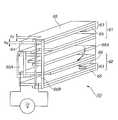
도 1은 본 발명에 관한 입출력 장치를 가지는 전자 기기를 나타낸 사시도이다.1 is a perspective view showing an electronic apparatus having an input / output device according to the present invention.
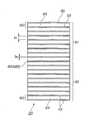
도 2는 도 1에 나타낸 전자 기기의 터치 패널과 지지 프레임 및 바이모르프형 압전 액추에이터를 나타낸 평면도이다.FIG. 2 is a plan view illustrating a touch panel, a support frame, and a bimorph piezoelectric actuator of the electronic device shown in FIG. 1.
도 3은 도 1에 나타낸 전자 기기의 분해 사시도이다.3 is an exploded perspective view of the electronic device shown in FIG. 1.
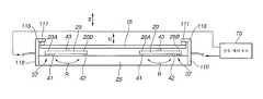
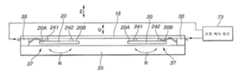
도 4는 도 3에 나타낸 전자 기기의 IV-IV선에 있어서의 단면도이다.It is sectional drawing in the IV-IV line of the electronic device shown in FIG.
도 5 (A)는 도 4에 나타낸 압전 액추에이터, 진동 전달 기구 등을 확대하여 나타낸 도면이며, 도 5 (B)는 돌기와 연질의 접착제와의 관계를 나타낸 사시도이다.Fig. 5A is an enlarged view of the piezoelectric actuator, vibration transmission mechanism, and the like shown in Fig. 4, and Fig. 5B is a perspective view showing the relationship between the projection and the soft adhesive.
도 6은 바이모르프형 압전 액추에이터를 일부를 생략하여 나타낸 사시도이다.6 is a perspective view showing a bimorph piezoelectric actuator with a part omitted.
도 7은 도 6에 나타낸 바이모르프형 압전 액추에이터의 적층 구조를 나타낸 단면도이다.FIG. 7 is a cross-sectional view illustrating a laminated structure of the bimorph piezoelectric actuator shown in FIG. 6.
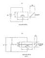
도 8 (A)는 단층의 바이모르프형 압전 액추에이터를 나타내고, 도 8 (B)는 복수층의 바이모르프형 압전 액추에이터를 나타낸 측면도이다.Fig. 8A shows a single layer bimorph piezoelectric actuator, and Fig. 8B is a side view showing a bilayer bimorph piezoelectric actuator.
도 9는 화상 표시부에 일례로서 표시된 아이콘 및 그들 아이콘에 대응하는 진동 제어 파형 패턴의 예를 나타낸 도면이다.9 is a diagram showing an example of an icon displayed as an example on an image display unit and a vibration control waveform pattern corresponding to the icon.
도 10은 입출력 장치를 포함하는 제어 블록을 나타낸 블록 회로도이다.10 is a block circuit diagram illustrating a control block including an input / output device.
도 11은 본 발명의 다른 예를 나타낸 단면도이다.11 is a cross-sectional view showing another example of the present invention.
도 12는 본 발명의 또 다른 예를 나타낸 단면도이다.12 is a cross-sectional view showing still another example of the present invention.
도 13은 본 발명의 또 다른 예를 나타낸 단면도이다.13 is a cross-sectional view showing still another example of the present invention.
도 14는 본 발명의 또 다른 예를 나타낸 단면도이다.14 is a sectional view showing still another example of the present invention.
도 15는 본 발명에 관한 입력 장치를 구성하는 제어 블록의 다른 예를 나타낸 블록 회로도이다.Fig. 15 is a block circuit diagram showing another example of the control block constituting the input device according to the present invention.
도 16은 본 발명에 관한 바이모르프형 압전 액추에이터에서 어느 특정 진동자에 한정했을 때, 터치 패널을 효율 양호하게 진동시키기 위한 진동 지령 방식의 예를 나타낸 도면이다.FIG. 16 is a view showing an example of the vibration command method for vibrating the touch panel with good efficiency when limited to any particular vibrator in the bimorph piezoelectric actuator according to the present invention.
이하, 본 발명의 바람직한 구체예를 도면을 참조하여 설명한다. 그리고, 이하에 설명하는 본 발명의 바람직한 구체예는 기술적으로 바람직한 여러 가지의 한정이 부여되어 있지만, 본 발명의 범위는 이하의 설명에서 특히 본 발명을 한정하는 취지의 기재가 없는 한, 이들 구체예에 한정되는 것은 아니다.Hereinafter, preferred embodiments of the present invention will be described with reference to the drawings. In addition, although the preferable specific example of this invention demonstrated below is provided with various technically preferable limitation, unless the meaning of limiting this invention is specifically described in the following description, these specific examples are given. It is not limited to.
본 발명에 관한 입출력 장치를 가지는 전자 기기(10)는 도 1에 나타낸 바와 같은 구성을 구비한 휴대 정보 단말(PDA)이다.An
본 발명이 적용된 전자 기기로서의 휴대 정보 단말(PDA)은 터치 패널에 촉각(진동)을 이용한 촉각 피드백 발생 기능을 부가함으로써, 정보의 종류에 따른 입력 조작에 대한 피드백을 사용자에 대하여 촉각으로 실현할 수 있다. 이 촉각에 의한 피드백은 종래부터 조작의 피드백으로서 일반적으로 이용되고 있는 클릭감이나 스트로크감 등과 감각적으로 가까운 것이며, 사용자에게 있어서는 화상이나 음에 의한 피드백과 비교하여, 보다 직감적이라고 하는 이점이 있다.As a portable information terminal (PDA) as an electronic device to which the present invention is applied, by adding a tactile feedback generation function using tactile (vibration) to a touch panel, feedback on an input operation according to the type of information can be realized tactilely to the user. . This tactile feedback is sensibly close to a click feeling, a stroke feeling, or the like, which has conventionally been used as feedback for operation, and has an advantage of being more intuitive for a user as compared to feedback by an image or sound.
또, 촉각 피드백 발생 기능에 의해, 입력 조작의 피드백뿐만 아니라, 종래부터 이용되고 있는 화상이나 음의 표시와 동일하게 다양한 정보를 사용자에게 제시할 수 있다.In addition, the tactile feedback generating function can present not only the feedback of the input operation but also various information to the user in the same way as the image and sound display used conventionally.
도 1에 나타낸 전자 기기(10)는, 개략적으로는 본체(13)와, 터치 패널(15)과, 복수개의 바이모르프형 압전 액추에이터(20)와, 입출력 장치(100)를 가지고 있다. 도 1에 나타낸 전자 기기(10)에서는, 4개의 바이모르프형 압전 액추에이터 (20)가 설치되어 있다. 본체(13)는 몇개인가의 키(16 내지 19)나 키(21, 22, 24) 그리고 전원 스위치(23)를 가지고 있다. 예를 들면 키(16)는 변환 키이며, 키(17)는 결정 키이며, 키(18)는 일본어와 영어의 절환 키 등이다. 본체(13)는 그 밖에도 필요한 키가 설치되어 있다.The
도 2는 도 1에 나타낸 터치 패널(15)과 본체(13)의 지지 프레임(25)을 나타내고 있다. 이 지지 프레임(25)의 4 코너의 위치에는, 긴 판형인 4개의 바이모르프형 압전 액추에이터(20)가 예를 들면 접착제에 의해 고정되어 있다.FIG. 2 shows the
도 3은 터치 패널(15)과 본체(13)를 나타낸 분해 사시도이다.3 is an exploded perspective view illustrating the
본체(13)는 전술한 바와 같이 화상 표시부의 지지 프레임(25)과, 화상 표시부(30)를 가지고 있다. 이 화상 표시부(30)는 액정 표시부를 사용할 수 있다. 화상 표시부(30)는 액정 표시부(LCD: Liquid Crystal Display) 이외에, 유기 EL(Electroluminescence)나 CRT(Cathode-ray tube) 등이라도 된다. 이 화상 표시부(30)에는, 예를 들면 도 1에 나타낸 키(24)를 조작함으로써, 필요한 아이콘(31 내지 34)을 일례로서 표시할 수 있다. 지지 프레임(25)은, 예를 들면 금속에 의해 만들어져 있고, 화상 표시부(30)의 4변 위치에 설치된 4변 형상의 프레임이다. 지지 프레임(25)의 세로 프레임부(25A, 25B)에는, 각각 2개씩의 바이모르프형 압전 액추에이터(20)가 간격을 두고 직렬로 접착제에 의해 고정되어 있다. 바이모르프형 압전 액추에이터(20)는 X 방향으로 평행으로 배열되어 있다. 이 X 방향은 본체(13)의 짧은 길이 방향인 Y 방향과 직각의 방향이다.The
본체(13)는, 예를 들면 플라스틱, 일례로서 PC(폴리카보네이트), ABS(아크릴 로니트릴 부타디엔 스틸렌), PI(폴리이미드) 등에 의해 만들어져 있지만, 특히 한정되는 것은 아니다. 지지 프레임(25)은 금속이나 플라스틱에 의해 만들 수 있지만, 예를 들면 알루미늄이나 철판, 스테인레스판에 의해 만들어져 있다. 화상 표시부(30)는, 예를 들면 컬러 표시를 할 수 있는 액정 표시부이다.The
터치 패널(15)은 투명의 필름이며, 예를 들면 얇은 폴리에스테르 필름을 채용할 수 있다. 이 터치 패널(15)에는 투명한 도전막(IT0)을, 예를 들면 직사각형으로 소정의 두께로 증착시킨 것이다. 이와 같은 폴리에스테르 필름을 2매 준비하고, 한쪽의 폴리에스테르 필름에는 세로 방향으로 직사각형으로 도전막이 형성되어 있고, 다른 쪽의 폴리에스테르 필름에는 가로 방향으로 직사각형으로 도전막이 형성되어 있다. 이와 같은 2매의 폴리에스테르 필름을 겹치고 그 사이에 전기 절연의 스페이서를 배치함으로써, 양쪽의 도전막이 그대로는 접촉하지 않도록 되어 있다. 그리고 사용자(이하, 조작자라고도 칭함)가 손가락으로 폴리에스테르 필름의 표면을 누름으로써, 한쪽 폴리에스테르 필름의 도전막과 다른 쪽 폴리에스테르 필름의 도전막을 통해 전류가 흘러, 좌표축의 X, Y의 교점으로부터, 도 3에 나타낸 화상 표시부(30)의 어느 위치를 누르고 있는가를 알 수 있는 구조로 되어 있다. 이 교점을 연결함으로써 흐르는 전류를 전기 회로에서 처리함으로써, 예를 들면 CPU(중앙 처리 장치)는 도 3에 나타낸 화상 표시부(30)의 어느 아이콘(31 내지 34)이 사용자에 의해 손가락으로 눌려졌는가를 판별한다. 이와 같은 터치 패널(15)의 형식은 특히 한정되지 않고, 각종의 것을 채용할 수 있다. 터치 패널(15)은 투명의 유리판과 투명의 필름을 겹쳐 형성해도 된다. 이 유리판 표면의 도전막과, 필 름 표면의 도전막이 접촉함으로써, 화상 표시부(30)의 어느 위치를 누르고 있는가를 알 수 있다.The
도 4는 도 3의 IV-IV선에 있어서의 전자 기기의 단면 구조예이다. 도 5 (A)는 도 4에 나타낸 전자 기기의 단면 구조의 일부를 확대하여 나타내고 있다.FIG. 4 is a cross-sectional structure example of an electronic device taken along line IV-IV of FIG. 3. FIG. 5A shows an enlarged part of the cross-sectional structure of the electronic device shown in FIG. 4.
도 4, 도 5 (A)에서, 터치 패널(15)과 지지 프레임(25) 사이에는, 전술한 4개의 바이모르프형 압전 액추에이터(20)가 배치되어 있다. 터치 패널(15)과 지지 프레임(25)의 간격을 설정하기 위해, 터치 패널 지지재(35)가 설치되어 있다. 이 터치 패널 지지재(35)는 유연성이 있고 또한 진동을 흡수하지 않는 재료에 의해 만들어져 있으며, 터치 패널(15)의 예를 들면 4 코너 위치에 위치하고 있다. 터치 패널(15)과 지지 프레임(25) 사이의 공간에는, 전술한 바이모르프형 압전 액추에이터(20)가 배치되어 있다. 이 바이모르프형 압전 액추에이터(20)와 진동 전달 기구는 진동 발생 디바이스를 구성하고 있다. 바이모르프형 압전 액추에이터(20)의 휨 변위에 의한 진동이 터치 패널(15)측에 전달되도록 되어 있다.4 and 5 (A), the four bimorph-
이하의 설명에서는, 바이모르프형 압전 액추에이터(20)는 단지 압전 액추에이터(20)라고 약칭하여 사용한다. 이 압전 액추에이터(20)의 일단부(20A)와 지지 프레임(25) 사이에는 제1 지지부(41)가 형성되어 있다. 동일하게 하여 압전 액추에이터(20)의 타단부(20B)와 지지 프레임(25) 사이에는 제2 지지부(42)가 형성되어 있다. 압전 액추에이터(20)의 중간 부분과, 터치 패널(15)의 배면 사이에는 제3 지지부(43)가 형성되어 있다.In the following description, the bimorph
도 5 (A) 및 도 5 (B)에서는, 제1 지지부(41), 제2 지지부(42) 및 제3 지지 부(43)가 확대되어 나타나 있다. 도 5 (A) 및 도 4에 나타낸 바와 같이, 압전 액추에이터(20)의 진동 변위는 화살표 U로 나타내고 있다. 이 진동 변위 U는 터치 패널(15)과 지지 프레임(25)에 대하여 수직 방향, 즉 화살표 Z 방향이다. 이 화살표 Z 방향은 도 3에 나타낸 X 방향과 Y 방향에 대하여 직교하는 방향이다.In FIG. 5 (A) and FIG. 5 (B), the
도 4, 도 5 (A)에 나타낸 바와 같이, 압전 액추에이터(20)는 터치 패널(15)과 지지 프레임(25) 사이에서, 제1 지지부(41)로부터 제3 지지부(43)를 사용하여, 3 점에 의해 지지되어 있다. 제1 지지부(41) 내지 제3 지지부(43)는 압전 액추에이터(20)가 발생하는 진동을 터치 패널(15)측에 전하는 이른바 전술한 진동 전달 기구(37)를 구성하고 있다. 제1 지지부(41) 내지 제3 지지부(43)는 도 5 (A)에 나타낸 바와 같이, 각각 나이프 에지형의 돌기(50)와 연질의 접착제(51)로 구성되어 있다. 제1 지지부(41) 내지 제3 지지부(43)는 각각의 지점에서 압전 액추에이터(20)의 휨 변형(굽힘 변형이라고도 함)의 방해가 되지 않도록, 나이프 에지형의 돌기(50)를 사용하여 압전 액추에이터(20)의 면을 지지하고 있다. 즉, 제1 지지부(41)의 돌기(50)는 지지 프레임(25)에 대하여 압전 액추에이터(20)를 R 방향으로 회전 가능하게 지지하고 있다. 동일하게 하여 제2 지지부(42)의 돌기(50)는 지지 프레임(25)에 대하여 압전 액추에이터(20)를 R 방향으로 회전 가능하게 지지하고 있다. 제3 지지부(43)의 돌기(50)는 터치 패널(15)에 대하여 압전 액추에이터(20)를 R 방향으로 회전 가능하게 지지하고 있다.As shown in FIG. 4, FIG. 5 (A), the
제1 지지부(41) 내지 제3 지지부(43)의 연질 접착제(51)는 각각의 돌기(50)를 지지 프레임(25)과 터치 패널(15)에 각각 접착하여 위치 어긋남을 일으키지 않 도록 하기 위해 사용하고 있다. 연질 접착제(51)의 재질로서는, 경질의 재료인 돌기를 접착하고 또한 압전 액추에이터(20)의 휨 변위를 줄이지 않고 터치 패널(15) 측에 전하는 재질을 채용할 수 있다. 이 연질 접착제의 재질로서는, 예를 들면 스틸렌계 엘라스토머[KG 겔: YMG-80-BK(기타가와 공업 주식회사)]이다.The
도 5 (B)에서는, 돌기(50)와 연질의 접착제(51)를 나타내고 있으며, 연질의 접착제(51)는 파선으로 나타내고 있다.In FIG. 5B, the
도 4와 도 5에 나타낸 압전 액추에이터(20)가 발생하는 진동 변위 U는 Z 방향으로 평행이다. 제1 지지부(41) 내지 제3 지지부(43)에서는, 전술한 바와 같이 나이프 에지형의 돌기(50)를 가지고, 접착제(51)로 고정되어 있기 때문에, 제1 지지부(41) 내지 제3 지지부(43)에서는 압전 액추에이터(20)는 R 방향에 따라 회전 방향 R로만 이동의 자유도를 가지고 있으며, 진동 변위 U에 따른 Z 방향으로는 위치가 구속되어 있다.Vibration displacement U which the
다음에, 도 6 및 도 7을 참조하여, 압전 액추에이터(20)의 구조예에 대하여 설명한다. 도 6은 압전 액추에이터(20)의 구조를 일부 생략하여 도시하고 있다. 압전 액추에이터(20)는, 이른바 바이모르프형 압전 액추에이터이다. 이 바이모르프형 압전 액추에이터는 바이모르프형 압전 진동자 등이라고도 불려지고 있다. 압전 액추에이터(20)는, 개략적으로는 제1 액추에이터 유닛(61)과 제2 액추에이터 유닛(62)을 적층하여 구성되어 있다.Next, with reference to FIG. 6 and FIG. 7, the structural example of the
제1 액추에이터 유닛(61)과 제2 액추에이터 유닛(62)의 구조는 거의 동일하며, 각각 복수개의 압전 소자층(63)을 가지고 있다. 이 압전 소자층(63)은 압전 소자(64)와 이 압전 소자(64)의 양면에 형성된 전극층(65)의 3층으로 구성되어 있다. 이 압전 소자층(63)은 소(素)액추에이터 유닛이라고도 불려지고 있다. 따라서 제1 액추에이터 유닛(61)과 제2 액추에이터 유닛(62)은 각각 복수개의 압전 소자층(63)을 적층함으로써 구성되어 있다. 도 6 및 도 7에 나타낸 예에서는, 제1 액추에이터 유닛(61)과 제2 액추에이터 유닛(62)은 각각 9층의 압전 소자층(63)을 적층하여 구성하고 있다. 압전 소자층(63)의 압전 소자(64)는, 예를 들면 PZT(티탄산지르콘산연)에 의해 만들어지고 있다. 전극층(65)은, 예를 들면 Ag-Pd에 의해 만들어지고 있다. 제1 액추에이터 유닛(61)과 제2 액추에이터 유닛(62) 사이에는 중간의 전극층(65A)이 형성되어 있다.The structures of the
도 6 및 도 7에 나타낸 압전 액추에이터(20)는 합계 18층의 압전 소자(64)와, 각 압전 소자(64) 사이의 전극층(65) 및 표리에 있는 전극층(65)의 합계 19층의 전극층(65)으로 구성되어 있다. 도 7에 나타낸 압전 소자(64)의 1층당 두께 D1은, 예를 들면 28㎛이다. 전극층(65)의 두께 D2는, 예를 들면 약 4㎛이다. 압전 액추에이터(20)는 전술한 압전 소자층(63)이 18개 적층된 구조이며, 각 압전 소자층(63)은 각각 전기적으로 병렬로 결합되어 있다.The
도 6에 나타낸 바와 같이 압전 액추에이터(20)에 대하여 층간 접속부(66A, 66B)를 형성하고, 이들 층간 접속부(66A, 66B)에 대하여 구동 전압을 인가한 경우에, 제1 액추에이터 유닛(61)의 9층 압전 소자층(63)이 신장/수축, 제2 액추에이터 유닛(62)의 9층 압전 소자층(63)이 수축/신장하도록, 각 압전 소자층(63)의 압전 소자(64)는 분극 처리가 행해지고 있다. 따라서, 바이모르프형 압전 액추에이터(20)는 결과적으로 바이메탈과 동일한 원리로 휨 변위되도록 되어 있다. 도 7에 나타낸 압전 액추에이터(20)의 합계 두께는, 예를 들면 500㎛이며, 매우 얇고 소형의 것이다. 이와 같은 적층형 압전 액추에이터(20)를 사용함으로써, 제1 액추에이터 유닛(61)과 제2 액추에이터 유닛(62)을 각각 단층의 압전 소자층에서 형성하는 경우에 비해, 한정된 구동 전압을 사용한 경우에 보다 큰 휨 변위를 발생시킬 수 있다. 제1 액추에이터 유닛(61)이 신장되면 제2 액추에이터 유닛(62)은 수축되고, 제1 액추에이터 유닛(61)이 수축되면 제2 액추에이터 유닛(62)이 신장된다고 하는 바와 같이, 압전 액추에이터(20)는 도 4에 나타낸 진동 변위 U에 따라 변위된다. 전술한 이 바이모르프형 압전 액추에이터(20)는 다층 바이모르프형 압전 액추에이터라고도 불려지고 있다.As shown in FIG. 6, when the
여기에서, 소형 휴대 기기에 특별히 적합한 바이모르프형 압전 액추에이터(20)의 동작에 대하여 설명한다.Here, the operation of the bimorph
도 1에 나타낸 바와 같은 휴대 전자 기기(10)는 통상 Li-ion이나 Ni-수소 배터리를 주전원으로서 사용하고 있다. 전술한 통상의 바이모르프형 압전 액추에이터 배터리에 상기 배터리가 발생하는 전압을 인가해도, 사용자에게 촉각으로서 지각하게 할 만큼의 휨 변위나 힘은 발생할 수 없다. 이 문제의 해결을 위해, 본 발명의 실시예에서는, 구조를 가지는 다층 바이모르프형 압전 액추에이터(20)를 사용하여, 동일한 휨 변위와 힘을 발생시키기 위해 필요한 구동 전압의 저전압화를 다음과 같이 도모한다.The portable
바이모르프형 압전 액추에이터(20)를 변형(구동)하기 위한 압전 소자의 왜곡량 △L1은 다음 식에서 주어진다.The distortion amount ΔL1 of the piezoelectric element for deforming (driving) the bimorph
△L1 = d31×E×LΔL1 = d31 × E × L
(d31: 압전 정수, E: 인가 전계 강도, L: 소자 길이)(d31: piezoelectric constant, E: applied field strength, L: element length)
왜곡량은 전계의 강도에 비례하므로, 저전압화해도 전계 강도를 일정하게 유지하면 왜곡량은 불변이다. 예를 들면, 도 8 (A)의 소자에는 2V, 도 8 (B)의 소자에는 1V의 전압이 인가되어 있지만, 도 8 (B)의 소자 두께가 도 8 (A)의 그것의 1/2이다. 이 때문에, 소자 내부의 전위 구배(句配), 즉 전계 강도는 양쪽 모두 동일하며, 결과적으로 왜곡량도 동일하다.Since the amount of distortion is proportional to the strength of the electric field, the amount of distortion remains unchanged when the field strength is kept constant even at low voltages. For example, although the voltage of 2V is applied to the device of FIG. 8A and 1V is applied to the device of FIG. 8B, the device thickness of FIG. 8B is 1/2 of that of FIG. 8A. to be. For this reason, the potential gradient inside the element, i.e., the electric field strength, is the same for both, and as a result, the amount of distortion is also the same.
이와 같이, 본 발명에서는 도 6 및 도 7과 같이, 소자를 두께 방향으로 분할함으로써, 저전압 구동이라도 사용자에게 촉각을 느끼게 하는 바이모르프형 압전 액추에이터(20)를 실현할 수 있다. 이 예의 경우의 액추에이터 변위량을, 예를 들면 20mm 스팬으로 양단을 지지했을 때의 중앙부 변위로서 표현하면, 인가 전압이 10V인 때, 중앙부 변위는 약 25㎛이다. 또한 소자의 두께를 분할하여, 예를 들면 Li-ion 배터리를 사용한 경우의 전압 약 3.3V로 상기와 동일하게 25㎛ 정도의 변위를 얻기 위해서는 1소자당 두께를 도 6의 약 1/3로 하면 되므로, 10㎛ 정도로 하면 실현된다.As described above, in the present invention, by dividing the element in the thickness direction as shown in Figs. 6 and 7, the bimorph
도 9에 나타낸 전자 기기(10)의 화상 표시부(30)에는, 예를 들면 4개의 아이콘(31 내지 34)이 표시되어 있다. 이 화상 표시부(30)의 위에는 전술한 터치 패널(15)이 배치되어 있다.For example, four
도 10은 도 9의 제어 블록의 예를 나타내고 있다. 전자 기기(10)의 제어 블록(70)은 진동 발생 디바이스(71), 진동 제어 회로(73), 터치 패널(15), 화상 표시부(30)를 가지고 있다. CPU(중앙 처리 장치)(74)는 전자 기기(10)의 본래의 휴대 정보 단말로서의 기능을 실현하기 위한 중앙 처리 장치이며, 이 CPU(74)는 화상 표시부(30)와 터치 패널(15) 등의 신호 처리를 행한다. 즉 CPU(74)는 화상 표시부(30)에 대하여 아이콘 등의 표시 신호 S5를 보내고, 터치 패널(15)로부터의 좌표값 S4가 CPU(74)에 공급되도록 되어 있다. 터치 패널(15)은 사용자의 손가락 F 또는 스타일러스(stylus)(펜)로 접촉하여 누르도록 되어 있다.10 shows an example of the control block of FIG. 9. The
진동 제어 회로(73)는 정보의 종류에 따라 상이한 진동 모드를 진동 발생 디바이스(71)에 발생시키기 위한 것이다. 이 진동 제어 회로(73)와 진동 발생 디바이스(71)는 통상 사용되고 있는 전자 기기(10)에는 없는 본 발명의 특징적인 부분이다. 진동 제어 회로(73)는 프로세서(80), 메모리(81), 외부 프로그램 포트(82), D/A 컨버터(83), 그리고 전류 앰프(84)를 가지고 있다. 프로세서(80)는 CPU(74)와 메모리(81)와 외부 프로그램 포트(82) 및 D/A 컨버터(83)에 접속되어 있다.The
메모리(81)는 도 10에 나타낸 바와 같은, 예를 들면 4개의 진동 모드인, 예를 들면 진동 제어 파형 패턴 P1 내지 P4를 기억하고 있다. 이 진동 제어 파형 패턴 P(P1 내지 P4)는 메모리(81)로부터 프로세서(80)에 공급할 수 있다. 이들 진동 제어 파형 패턴 P1 내지 P4는 도 9에 나타낸 아이콘(31 내지 34)에 각각 대응한 패턴이다. 아이콘(31 내지 34)은 각각 상이한 정보의 예이며, 이 4 종류의 아이콘(31 내지 34)은 화상 표시부(30)에 임의로 표시할 수 있다.The
이 디지털 신호인 진동 제어 파형 패턴 P는 프로세서(80)에 공급된다. 메모리(81)에 대하여 디지털 신호인 진동 제어 파형 패턴 P를 공급하게 하는 방법으로서는, 외부의 퍼스널 컴퓨터 등 외부 프로그래머(75)에 의해 생성된 임의의 진동 제어 파형 패턴을, 외부 프로그램 포트(82)를 통해 프로세서(80)에 수용하고, 진동 제어 파형 패턴 P의 등록 번호 및 성질을 부여한 후 메모리(81)에 등록시키는 방법이 있다. 메모리(81)에 진동 제어 파형 패턴을 기억시키는 다른 방법으로서는, 터치 패널(15)로부터 입력되는 파형의 정보에 따라, 프로세서(80)는 진동 제어 파형 패턴을 생성하고, 역시 등록 번호와 성질을 부여한 후 메모리(81)에 공급시킨다. 이와 같이, 외부 프로그램 포트(82)는 외부의 퍼스널 컴퓨터나 그 밖의 외부적인 수단에 의해 생성된 전술한 바와 같은 진동 제어 파형 패턴을 프로세서(80)를 통해 메모리(81)에 수용하기 위한 포트이다.The vibration control waveform pattern P which is this digital signal is supplied to the
프로세서(80)는 CPU(74)로부터 보내지는 예를 들면 터치 패널(15) 상의 좌 표값 S4(좌표 정보)에 따른 요구 신호 좌표값 S에 의해, 메모리(81)로부터 그 요구 신호 좌표값 S에 따른 진동 제어 파형 패턴 P(P1∼P4)를 선택하고, 디지털 파형 S1로서 D/A 컨버터(83)에 출력하는 신호 처리를 행한다. 이 좌표값 S4(좌표 정보)는 도 9에 나타낸 화상 표시부(30)의 정보로서의 아이콘(31 내지 34)의 좌표와 링크되어 있다. 프로세서(80)는 이미 설명한 바와 같이 외부적인 프로그램 수단을 사용하지 않고, 휴대 정보 단말로서의 전자 기기(10)에 저장할 수 있는 터치 패널(15) 등의 입력 수단에 의해 입력된 정보에 의해, 진동 발생 수단(71)의 압전 액추에이터(20)를 동작시키는 진동 제어 파형 패턴 P를 생성하는 등의 신호 처리를 행할 수 도 있다. 이와 같이 프로세서(80)와 CPU(74) 사이에서는, 좌표값 S4에 따른 요구 신호 좌표값 S를 교환함으로써, 터치 패널(15)의 좌표값 S4를 프로세서(80)에 수용할 수 있다.The
프로세서(80)는 D/A 컨버터(83)에 대하여 디지털 파형 S1을 보내면, D/A 컨버터(83)는 이 디지털 파형 S1을 아날로그 전압 파형 S2로 변환한다. 전류 앰프(84)는 이 아날로그 전압 파형 S2를, 압전 액추에이터(20)에 대하여 압전 액추에이터(20)를 구동하기 위해 충분한 전류를 가진 전압의 지령값 S3을 생성하여 진동 발생 디바이스(71)의 압전 액추에이터(20)에 보낸다. 이 전류 앰프(84)는 아날로그 전압 파형 S2를, 압전 액추에이터(20)를 구동하기 위해 충분한 전류가 되도록 전류적으로 증폭하여 압전 액추에이터(20)에 출력하는 것인다.The
도 10에 나타낸 진동 발생 디바이스(71)는 압전 액추에이터(20)와 진동 전달 기구(37)를 가지고 있다.The
진동 전달 기구(37)는 도 4에 나타낸 바와 같이 제1 지지부(41) 내지 제3 지지부(43)를 가지고 있는 것은 이미 설명하고 있다. 압전 액추에이터(20)는 전류 앰프(84)로부터의 지령값 S3을 기계적인 휨 변위로 변환한다. 진동 전달 기구(37)는 압전 액추에이터(20)의 휨 변위를 도 4에 나타낸 터치 패널(15)에 대하여 전한다. 도 1과 도 3에 나타낸 휴대형 정보 단말과 같은 전자 기기(10)는 도 10의 입출력 장치(100)를 가지고 있다. 이 입출력 장치(100)는 도 10에 나타낸 바와 같이 화상 표시부(30), 터치 패널(15), 진동 발생 디바이스(71) 및 진동 제어 회로(73)를 가지고 있다.The
다음에, 전술한 입출력 장치(100)를 가지는 전자 기기(10)의 동작에 대하여 설명한다.Next, the operation of the
사용자는 도 9에 나타낸 바와 같은 화상 표시부(30)의 아이콘(31 내지 34)을 일례로서 보고 있다. 이들 아이콘(31 내지 34)은 각각 상이한 정보를 나타내고 있다. 사용자가 아이콘(31)을 터치 패널(15)을 통해 손가락으로 접촉하면, 화상 표시부(30)의 화면 상의 좌표가 도 10에 나타낸 터치 패널(15)로부터 좌표값 S4로서 CPU(74)에 보내진다. 아이콘(31)과 이 아이콘(31)의 좌표값 S4는 미리 CPU(74) 내에서 관계지어져 있다. CPU(74)로부터 사용자가 접촉한 아이콘(31)을 나타내는 신호(예를 들면, 클릭 아이콘)가 요구 신호 좌표값 S로서 프로세서(80)에 보내지면, 프로세서(80)는 그 아이콘(31)에 적합한 진동 제어 파형 패턴 P1을 메모리(81)로부터 호출하여, 디지털 파형 S1로서 D/A 컨버터(83)에 출력한다.The user sees
D/A 컨버터(83)는 프로세서(80)로부터의 디지털 파형 S1을 아날로그 전압 파형 S2로 변환한다. 전류 앰프(84)는 아날로그 전압 파형 S2의 전류값을 증폭하여, 지령값 S3을 압전 액추에이터(20)에 공급한다. 압전 액추에이터(20)는 주어진 지령값 S3(전압값)에 따라 기계적으로 휨 변형을 한다. 이 때, 압전 액추에이터(20)는 도 4에 나타낸 바와 같이 제1 지지부(41) 내지 제3 지지부(43)에 따라서는 휨 변형을 저해하는 일이 없도록 자유도를 가지고 있다. 즉 전술한 바와 같이, 제1 지지부(41) 내지 제3 지지부(43)는 도 5 (A)에 나타낸 바와 같이 화살표 R 방향의 회전 방향으로는 자유도를 가지고 있지만, 진동 변위의 방향인 화살표 U 방향으로는 위치 변위는 하지 않는다. 이 때문에, 압전 액추에이터(20)가 휨 변형함으로 써, 터치 패널(15)은 진동 변위 U에 따라서만 변위하는 것이다. 압전 액추에이터(20) 중앙부의 연속적인 이와 같은 진동 변위 U는 터치 패널(15)의 연속적인 변위를 닮아 즉 진동의 파형으로서 사용자의 손가락 F에 촉각 피드백 TB로서 제시된다.The D /
이와 같이 하여, 본 발명에서는 터치 패널에 촉각(진동)을 이용한 촉각 피드백 발생 기능을 부가함으로써, 입력 조작에 대한 피드백을 촉각으로 실현할 수 있다. 이 촉각에 의한 피드백은 종래부터 조작의 피드백으로서 일반적으로 이용되고 있는 클릭감이나 스트로크감 등과 감각적으로 가까운 것이며, 사용자로부터 보아 화상이나 음에 의한 피드백과 비교하여, 보다 직감적이라고 하는 이점이 있다. 그리고, 피드백 정보뿐만 아니라, 촉각 정보의 표시 기능도 있다.In this way, in the present invention, by adding a haptic feedback generation function using tactile (vibration) to the touch panel, the feedback on the input operation can be realized tactilely. This tactile feedback is sensibly close to a click feeling, a stroke feeling, or the like, which has conventionally been used as feedback for operation, and has an advantage of being more intuitive as compared to feedback by an image or sound when viewed from a user. In addition to the feedback information, there is also a display function of the tactile information.
도 9에 나타낸 다른 아이콘(32)을 선택함으로써, 전술한 바와 같은 동일 요령으로, 진동 제어 파형 패턴 P2가 메모리(81)로부터 호출되어 전류 앰프(84)로부터의 지령값 S3에 따라 압전 액추에이터(20)가 진동 제어 파형 패턴 P2에 따라 진동한다. 동일하게 하여 아이콘(33)을 사용자가 손가락으로 누름으로써, 진동 제어 파형 패턴 P3에 따라 압전 액추에이터(20)가 진동 변위를 일으킨다. 사용자가 아이콘(34)을 누름으로써, 진동 제어 파형 패턴 P4에 따라 압전 액추에이터(20)가 진동 변위를 일으킨다.By selecting the
도 9에 나타낸 바와 같이, 진동 제어 파형 패턴 P1은 클릭감, 즉 강성감(剛性感)을 발생하는 이른바 직사각형파 패턴이다. 진동 제어 파형 패턴 P2는 하트 비트와 같은 리듬 감각을 느끼는 디지털 파형이며, 그 펄스폭은 임의로 설정되어 있다. 진동 제어 파형 패턴 P3은 연속적인 모션을 발생하는 동작감을 느끼는 파형 이며, 계단형의 파형이다. 진동 제어 파형 패턴 P4는 보통 터치 패널의 반응, 즉 거의 일정한 진동 변위이다. 이와 같이, 아이콘(31 내지 34)은 각각 상이한 정보를 표시하고 있지만, 이들 아이콘(31 내지 34)에 따라, 상이한 진동 제어 파형 패턴 P1 내지 P4를 각각 할당하고 있다. 이 때문에, 진동 제어 파형 패턴 P1 내지 P4에 따라 압전 액추에이터(20)가 상이한 진동 변위를 일으킴으로써, 사용자는 손가락을 통해 아이콘(31 내지 34)의 종류를 직감적 또한 체감적으로 느낄 수 있는 것이다. 그리고, 아이콘(31 내지 34)과 그들의 좌표값과 그리고 진동 제어 파형 패턴의 관련짓기는 도 10에 나타낸 프로세서(80)에서 행하도록 해도 된다. CPU(74)와 프로세서(80)의 신호 처리의 분담은 여러 가지 고려되지만, 전술한 도 10에 나타낸 예에 특히 한정되는 것도 아니다.As shown in Fig. 9, the vibration control waveform pattern P1 is a so-called rectangular wave pattern that generates a feeling of click, that is, a sense of rigidity. The vibration control waveform pattern P2 is a digital waveform which feels a rhythmic sensation like a heartbeat, and the pulse width is arbitrarily set. The vibration control waveform pattern P3 is a waveform which feels the motion which produces a continuous motion, and is a stepped waveform. The vibration control waveform pattern P4 is usually a response of the touch panel, that is, almost constant vibration displacement. As described above, the
도 11 및 도 12는 본 발명의 또 다른 구체예를 나타내고 있다. 도 11 및 도 12의 각각에 나타낸 예는 도 4에 나타낸 예에 대하여 추가로 부가적인 요소를 가지고 있다. 도 11에 나타낸 예와 도 12에 나타낸 예의 구성 요소가, 도 4에 나타낸 예와 동일한 구성 요소에 대해서는 동일한 부호를 붙여 설명한다.11 and 12 show another embodiment of the present invention. The examples shown in each of FIGS. 11 and 12 have additional elements in addition to the example shown in FIG. 4. The components of the example illustrated in FIG. 11 and the example illustrated in FIG. 12 are described with the same reference numerals for the same components as those illustrated in FIG. 4.
도 11에 나타낸 예의 상이한 구성은 터치 패널(15)과 지지 프레임(25) 사이에, 패널 누름 프레임(110)이 설치되어 있는 것이다. 이 패널 누름 프레임(110)은 터치 패널(15)의 단부를 지지 프레임(25)에 대하여 고정하기 위한 대략 단면 L자형의 부재이며, 예를 들면 4변을 가지는 프레임이다. 이 패널 누름 프레임(110)의 상단부(111)와 터치 패널(15)의 단부 사이에는 더스트 실(113)이 형성되어 있다. 이 더스트 실(113)은, 예를 들면 링형이며, 대략 단면 방형상, 단면 원형상 또는 단면 타원 형상의 탄력성을 가지는 부재이며, 예를 들면 플라스틱이나 고무에 의해 만들어져 있다. 이 더스트 실(113)은 터치 패널(15)과 지지 프레임(25) 사이의 공간에 먼지나 쓰레기 등의 더스트가 침입하는 것을 방지하기 위한 실이다. 또한 이 더스트 실(113)은 터치 패널(15)을 패널 누름 프레임(110)에 대하여 지지하기 위한 터치 패널 지지재의 역할도 다하고 있다. 더스트 실(113)은 매우 유연성을 가진 재료이거나, 어느 정도 유연성과 진동을 감쇠하지 않는 특성을 가진 재료로 만들어져 있어, 압전 액추에이터(20)가 발생하는 진동 변위의 감쇠를 최소로 하는 작용을 가진다.In the different configuration of the example shown in FIG. 11, the
도 12에 나타낸 또 다른 예에서는, 도 11의 더스트 실(113) 및 패널 누름 프레임(110)에 더하여 압전 액추에이터(20)의 진동 전달 기구(137)의 구조가 상이하게 되어 있다. 도 4에서는, 제1 지지부(41) 내지 제3 지지부(43)를 사용하여 압전 액추에이터(20)가 터치 패널(15)과 지지 프레임(25) 사이에 3점으로 지지되어 있다. 이에 대하여 도 12의 실시예에서는, 진동 전달 기구(137)는 지지부(141)와 또 하나의 지지부(142)를 가지고 있다. 지지부(141)는 압전 액추에이터(20)의 일단부(20A)와 지지 프레임(25) 사이에 배치되어 있다. 또 하나의 지지부(142)는 압전 액추에이터(20)의 타단부(20B)와 터치 패널(15)의 내면 사이에 배치되어 있다. 지지부(142)는 도 5 (A) 및 도 5 (B)에 나타낸 돌기(50)와 연질의 접착제(51) 를 가지는 구성예와 동일하다. 지지부(141)는 경질의 접착제에 의해 화상 표시부의 지지 프레임(25)에 견고하게 고정되어 있다. 이와 같이 압전 액추에이터(20)는 지지부(141, 142)를 사용한 2점 지지로 터치 패널(15)과 지지 프레임(25) 사이에 지지 되어 있다. 압전 액추에이터(20)가 휨 변위하면, 터치 패널(15)은 진동 변위 U에 따라 변위된다. 이와 같은 압전 액추에이터(20)는 이른바 캔틸레버식으로 터치 패널(15)과 지지 프레임(25) 사이에 지지되어 있다.In another example shown in FIG. 12, in addition to the
다음에, 도 13 및 도 14는 본 발명의 또 다른 예를 나타내고 있다.13 and 14 show yet another example of the present invention.
도 13에 나타낸 예는 압전 액추에이터(20)가 터치 패널(15)의 내면측에만 지지되어 있는 것이 특징적이다. 압전 액추에이터(20)의 일단부(20A)는 지지부(241)에 의해 지지되어 있고, 압전 액추에이터(20)의 타단부(20B)는 지지부(242)를 사용하여 지지되어 있다. 이와 같은 구조를 채용해도, 압전 액추에이터(20)는 R 방향에 따라 회전 방향으로 자유도를 가지고 있지만, 진동 변위 U에 따라 터치 패널(15)에 진동을 발생시킬 수 있다.In the example shown in FIG. 13, the
도 14에 나타낸 예는 도 13에 나타낸 예에서, 압전 액추에이터(20)의 중간 부분에 추(250)가 추가로 고정되어 있다. 이 추(250)의 관성력이 압전 액추에이터(20)의 진동 변위 U를 일으키는 경우에 발생한다. 압전 액추에이터(20)가 터치 패널(15)을 밀어 올릴 때의 반력(反力)을, 이 추(250)의 관성력이 지지하므로, 압전 액추에이터(20)의 휨 변위를 효율 양호하게 터치 패널(15)에 전달할 수 있는 것이다. 도 13 및 도 14와 같이, 압전 액추에이터(20)가 터치 패널(15)측에만 지지되는 구성을 채용함으로써, 다음과 같은 이점이 있다. 즉, 사용자가 터치 패널(15)을 눌렀을 때의 힘이 압전 액추에이터(20)에 직접 가해지는 일이 없으므로, 사용자가 잘못하여 과도한 힘으로 터치 패널(15)을 눌러 버린 경우라도, 압전 액추에이터(20)에는 외력 부하가 가해지지 않게 된다.In the example shown in FIG. 14, in the example shown in FIG. 13, a
도 15는 도 10의 제어 블록(70)의 또 다른 예를 나타내고 있다. 도 15에 나타낸 제어 블록(70)이 도 10의 제어 블록(70)과 상이한 것은 다음의 점이다. 즉, 진동 제어 회로(73)는 A/D 컨버터(89)를 가지고 있는 것이다. 이 A/D 컨버터(89)는 압전 액추에이터(20)의 단자 사이의 전압 S6을 측정하기 위해 이 전압 S6을 수용하여 아날로그/디지털 변환하고 디지털 전압 S10을 프로세서(80)에 보낸다. 본 발명에서는, 압전 액추에이터(20)와 터치 패널(15)은, 예를 들면 도 4에 나타낸 바와 같이 직접 연결되어 있으므로, 사용자가 터치 패널(15)을 누르는 힘은 그대로 압전 액추에이터(20)에 전해진다. 따라서, 압전 액추에이터(20)와 터치 패널(15)의 걸어맞춤부는 힘에 따라 변위된다. 압전 액추에이터(20)는 이 변위를 주면, 거기에 비례한 기전력을 발생하는 성질이 있으므로, 이 기전력을 측정함으로써 사용자의 손가락 F의 조작력(가압력)을 프로세서(80)가 알 수 있다. 이와 같이 사용자의 손가락 F가 터치 패널(15)을 누름으로써 생기는 가압력 W에 따른 압전 액추에이터(20)의 전압 S6을, 프로세서(80)가 리얼 타임으로 측정할 수 있음에 따라 다음과 같은 메리트가 있다.FIG. 15 shows another example of the
즉, 사용자의 손가락 F가 터치 패널(15)을 과도한 힘으로 조작한 경우에는, 예를 들면 프로세서(80)가 CPU(74)에 지령하여 화상 표시부(30)에 대하여 과도한 힘에 의한 조작을 나타낸 아이콘의 표시 신호 S5를 공급하여, 화상 표시부(30)에 그 아이콘을 표시시킴으로서 사용자에게 과도한 힘을 더하고 있는 것의 주의를 촉구할 수 있다. 입력 펜을 사용한 자필 입력시 등의 사용자의 조작력[필압(筆壓)]을 측정하고, 사용자와 대응시켜 기억해 둠으로써, 사용자의 특정(인증)을 할 수 있다. 터치 패널(15)로부터 얻어지는 좌표의 정보(2차원 좌표 정보)와, 사용자의 조작력의 정보를 조합하여, 3차원 입력 장치로서 동작시키는 것도 고려된다.That is, when the user's finger F operates the
다음에, 도 16은 어느 특정 진동수에 한정했을 때, 터치 패널(15)을 효율 양호하게 진동시키기 위한 진동 지령 방식의 예에 대하여 나타내고 있다.Next, FIG. 16 has shown the example of the vibration command system for vibrating the
터치 패널(15) 및 그 제1∼제3 지지부(41, 42, 43)의 모든 것을 하나의 진동계로서 생각했을 때, 터치 패널(15)의 질량을 m, 터치 패널(15)과 걸어 맞추어져 있는 모든 부재의 스프링 정수(定數)를 Kt, 점성(粘性) 계수를 Ct로 하면, 계의 고유 진동수 f는 다음 식에서 주어진다.When the
f=1/2π×(Kt/m-(Ct/ 2m))1/2f = 1 / 2π × (Kt / m- (Ct / 2m))1/2
도 10의 진동 제어 회로(73)로부터, 상기 고유 진동수를 포함하는 진동 파형을 지령값으로서 출력함으로써, 터치 패널(15)을 효율 양호하게 진동시킬 수 있다. 여기에서 고유 진동수를 포함하는 진동 파형과는 정현파 등의 연속적인 진동뿐만 아니라, 임펄스적인 가진(加振)과 같이 다양한 진동수 성분이 복합된 것의 경우도 있다. 그리고, 계(系)의 고유 진동수를 인간이 촉각을 감지하기 쉬운 50Hz∼300Hz 정도의 범위로 조정하기 위해서는, 터치 패널 지지부 등의 재료나 형상 등을 변경하여, 전술한 스프링 정수 Kt나 점성 계수 Ct를 적당한 값으로 하면 된다.By outputting the vibration waveform containing the natural frequency as a command value from the
바이모르프형 압전 액추에이터의 압전 소자층은, 바람직하게는 4층 이상 있는 다층 바이모르프형 압전 액추에이터가 바람직하다. 특히, PDA 등의 휴대 기기를 고려한 경우, 구동 전압의 제약 때문에 통상의 압전 액추에이터는 사용할 수 없 다. 압전층을 다층화함으로써 비교적 저전압으로 구동이 가능한 액추에이터를 실현하여 그것을 터치 패널에의 촉각 피드백에 사용함으로써, 휴대 기기에서도 촉각 피드백이 있는 터치 패널을 실현할 수 있었다. 바이모르프형 압전 액추에이터의 양단부 및 중앙부의 각 지지부는 회전 방향으로는 자유도가 있어, 촉각을 전하는 방향(액추에이터 중앙부의 변위 방향)을 구속한다. 촉각을 전하는 방향의 구속으로서 액추에이터의 변형을 방해하지 않는 점 또는 선형의 돌기를 사용하고, 액추에이터와 그 지지체의 접합을 위해서는 연질의 접착제를 사용한다.The piezoelectric element layer of the bimorph piezoelectric actuator is preferably a multilayer bimorph piezoelectric actuator having four or more layers. In particular, when a portable device such as a PDA is considered, a conventional piezoelectric actuator cannot be used due to the limitation of the driving voltage. By multiplying the piezoelectric layer, an actuator capable of driving at a relatively low voltage is realized and used for tactile feedback to the touch panel, whereby a touch panel with tactile feedback can be realized even in a portable device. Each of the supporting portions at both ends and the central portion of the bimorph piezoelectric actuator has a degree of freedom in the rotational direction, thereby restraining the direction of the tactile transmission (displacement direction of the actuator central portion). As a restraint in the direction of conveying the tactile sense, points or linear protrusions that do not interfere with the deformation of the actuator are used, and a soft adhesive is used for joining the actuator and the support.
액추에이터가 발생하는 진동적 변위(속도)를 손상하지 않기 위해, 액추에이터 자체를 터치 패널의 지지체로 한다. 터치 패널을 지지하는 재료는 터치 패널과 화상 표시부 등의 표시 장치 사이에 먼지 등이 침입하는 것을 방지하는 더스트 실을 겸하고 있다. 터치 패널과 그 지지체를 포함한 진동계의 고유 진동수를 인간이 촉지(觸知)하기 쉬운 주파수 영역에 설정하고, 또한 그 고유 진동수 그 자체/그 진동수를 포함한 진동으로 터치 패널을 가진(加振)함으로써, 사용자에게는 효율적으로 촉각 피드백을 준다.In order not to damage the vibrational displacement (speed) in which the actuator is generated, the actuator itself is used as the support of the touch panel. The material supporting the touch panel also serves as a dust seal that prevents dust and the like from entering between the touch panel and display devices such as an image display unit. By setting the natural frequency of the vibration system including the touch panel and its support in a frequency range where humans are easy to touch, and having the touch panel with the natural frequency itself / vibration including the frequency, Give the user haptic feedback efficiently.
진동 제어 회로는 하나 또는 복수개의 제어 패턴(진동 파형)을 기억하고 있으며, 사용자나 선택하는 터치 패널 상의 좌표(통상 아이콘 등과 링크되어 있는)에 따라 적당한 제어 패턴을 기기가 선택하여 액추에이터를 제어한다. 이 진동 제어 회로가 기억하고 있는 제어 패턴은 소프트웨어에 의해 정의되어 있고, 메이커 또는 사용자가 임의로 재기록하는 것이 가능하다. 진동 제어 회로는 액추에이터에 외력이 가해짐으로써 생기는 기전력을 검지하는 수단을 구비하고 있으며, 사용자가 입 력 조작을 행할 때의 가압력을 측정할 수 있다.The vibration control circuit stores one or a plurality of control patterns (vibration waveforms), and the device selects an appropriate control pattern according to the user or coordinates (usually linked to an icon or the like) on the touch panel to select and controls the actuator. The control pattern stored in this vibration control circuit is defined by software and can be rewritten by the manufacturer or the user arbitrarily. The vibration control circuit is provided with a means for detecting an electromotive force generated by an external force applied to the actuator, and can measure the pressing force when the user performs an input operation.
바이모르프형 압전 액추에이터의 편단부(片端部)만을 베이스 등에 고정하고, 또 한쪽의 단부는 터치 패널과 연결되어 있는 구조도 채용할 수 있다.A structure in which only one end of the bimorph piezoelectric actuator is fixed to the base or the like and one end thereof is connected to the touch panel can also be adopted.
압전 액추에이터가 발생하는 진동적 변위(속도)를 손상하지 않기 위해, 덤핑 효과가 적고 또한 유연한 재료(예를 들면, 기타가와 공업 주식회사제의 KG 겔)를 통해 터치 패널을 지지한다. 압전 액추에이터의 휨 변형을 방해하지 않도록 압전 액추에이터는 터치 패널 하면에 지지하고, 압전 액추에이터가 변위됨으로써 생기는 진동을 터치 패널에 전한다. 이 경우에, 압전 액추에이터의 중앙부에는 추가 부가 되도록 해도 된다.In order not to damage the vibrational displacement (speed) generated by the piezoelectric actuator, the touch panel is supported by a material having a low dumping effect and a flexible material (for example, KG gel manufactured by Kitagawa Industries, Ltd.). The piezoelectric actuator is supported on the lower surface of the touch panel so as not to disturb the bending deformation of the piezoelectric actuator, and transmits the vibration generated by the displacement of the piezoelectric actuator to the touch panel. In this case, you may make it add to the center part of a piezoelectric actuator.
바이모르프형 압전 액추에이터를 사용함으로써, 휴대 기기에 적당한 소형(박형)이며 저소비 전력이라고 하는 특징을 가진 촉각 피드백 시스템을 구축할 수 있다. 특히 다층 바이모르프형 압전 액추에이터로 함으로써, 상기 특징 외에, 휴대 기기로 통상 사용되는 Li-ion식이나 Ni-수소식 등의 배터리를 전원으로 하여 동작하는 저전압 구동형 촉각 피드백 시스템의 구축이 가능하다. 간소하고 염가의 구조로 바이모르프형 압전 액추에이터의 지지가 실현된다. 액추에이터 자체가 터치 패널의 지지체가 되므로, 지지체에 의한 진동의 로스가 없을 뿐만 아니라, 구조가 심플하게 되어 염가의 시스템을 제공할 수 있다. 터치 패널의 지지부재가 더스트 실의 기능도 겸하고 있으므로 부재의 개수를 줄이는 것이 가능하며 결과로서 염가의 시스템을 제공할 수 있다. 액추에이터의 출력을 작게 해도 사용자가 촉지할 수 있는 진동을 발생시킬 수 있으므로, 소형이며 염가의 시스템을 제공할 수 있다.By using a bimorph piezoelectric actuator, it is possible to construct a tactile feedback system having a characteristic of being small (thin) and low power consumption suitable for portable devices. In particular, by using a multilayer bimorph piezoelectric actuator, in addition to the above-described features, it is possible to construct a low-voltage driven tactile feedback system which operates by using a battery such as a Li-ion type or a Ni-hydrogen type which is commonly used as a portable device. The support of the bimorph piezoelectric actuator is realized with a simple and inexpensive structure. Since the actuator itself serves as a support of the touch panel, not only does there be no loss of vibration due to the support, but also the structure is simple, so that an inexpensive system can be provided. Since the support member of the touch panel also functions as a dust seal, it is possible to reduce the number of members and, as a result, to provide an inexpensive system. Even if the output of the actuator is made small, it can generate vibrations that can be touched by the user, thereby providing a compact and inexpensive system.
입력 장치는 임의 파형을 가진 진동(촉각) 피드백이 가능하므로, 입력 동작의 확인으로서의 조작감을 비롯하여, 다양한 촉각 정보(감각)를 사용자에게 제공할 수 있다. 이 촉각 정보는 시각 정보나 청각 정보에 더한 제3 정보 제시 채널로서 활용함으로써, 사용자에 대하여 보다 리얼리티가 높은, 풍부한 정보 제공이 가능하다. 또한 촉각은 시각이나 청각과 비교하여 인간에 있어서 보다 근원적인 감각인 것을 사용하여, 인간의 감정을 표현할 수 있는 가능성도 있다. 또, 촉각 피드백을 단독으로 사용하는 것도 상정된다. 이 경우에는 맹인에의 정보 제시로부터, 운전 중이나 소음 환경하 또는 어떠한 상황에 따라 시각·청각 정보를 기대할 수 없는 경우에, 이른바 블라인드 조작을 가능하게 한다. 진동 파형을 용이하게 재기록하거나, 가하거나 할 수 있기 때문에, 예를 들면 기기가 사용되는 나라마다의 진동 파형의 설정이나, 사용자의 기호에 맞춘 진동 패턴의 설정이 가능하다. 또, 각각의 사용자가 작성한 진동 패턴을 예를 들면 네트워크를 통해 다른 사용자에게 제공하는 것도 가능하다.Since the input device is capable of vibration (tactile) feedback having an arbitrary waveform, various types of tactile information (sense) can be provided to the user, including a feeling of operation as confirmation of the input operation. By using this tactile information as a third information presentation channel in addition to visual information and audio information, rich information with higher reality can be provided to the user. There is also the possibility that the sense of touch can express human emotions by using the senses that are more fundamental to humans than visual or auditory senses. It is also assumed to use tactile feedback alone. In this case, so-called blind operation is made possible when visual and audio information cannot be expected from driving information, in a noise environment, or under any circumstances from the presentation of information to the blind. Since the vibration waveform can be easily rewritten or added, for example, it is possible to set the vibration waveform for each country in which the apparatus is used or to set the vibration pattern in accordance with the user's preference. Moreover, it is also possible to provide the vibration pattern which each user created to another user through a network, for example.
사용자가 기기를 어떻게 사용하고 있는지 상황을 알 수 있으므로 사용자에 의한 기기의 파괴 등을 미연에 방지할 수 있다. 또 촉각을 제시하기 위해 필요한 부품과 조작력을 검지하기 위한 부품의 대부분을 공통으로 사용할 수 있으므로, 염가의 3차원 입력 디바이스를 제공할 수 있다. 터치 패널을 지지하는 재료가 유연성을 가지고 있기 때문에 압전 액추에이터가 발생하는 변위가 기계적으로 억제되지 않고, 또한 그 재료가 진동을 흡수하는 특성(예를 들면 고무와 같이)을 작게 하고 있으므로, 압전 액추에이터가 발생하는 에너지를 효율 양호하게 터치 패널에 전달 할 수 있다. 사용자가 터치 패널을 눌렀을 때의 힘이 압전 액추에이터에 가해지는 일이 없으므로, 사용자가 잘못하여 과도함 힘으로 터치 패널을 눌러 버렸을 때도 압전 액추에이터에의 외력 부하가 없다. 추의 관성력이, 압전 액추에이터가 터치 패널을 밀어 올릴 때의 반력을 지지하므로, 압전 액추에이터의 변위를 효율 양호하게 터치 패널에 전달할 수 있다.By knowing how the user is using the device, it is possible to prevent the device from being destroyed by the user. In addition, since most of the parts necessary for presenting the tactile sense and the parts for detecting the operating force can be used in common, an inexpensive three-dimensional input device can be provided. Since the material supporting the touch panel is flexible, the displacement generated by the piezoelectric actuator is not suppressed mechanically, and the piezoelectric actuator is made to have a small property of absorbing vibration (such as rubber). The generated energy can be transmitted to the touch panel with good efficiency. Since the force when the user presses the touch panel is not applied to the piezoelectric actuator, there is no external force load on the piezoelectric actuator even when the user accidentally presses the touch panel with excessive force. Since the inertial force of the weight supports the reaction force when the piezoelectric actuator pushes up the touch panel, the displacement of the piezoelectric actuator can be efficiently transmitted to the touch panel.
단, 본 발명은 전술한 예에 한정되는 것이 아니다. 예를 들면, 바이모르프형 압전 액추에이터(20)의 제1 액추에이터 유닛과 제2 액추에이터 유닛의 적층 구조의 예로서는, 각각 9층의 압전 소자층(63)을 가지고 있다. 그러나 이 압전 소자층(63)의 적층수는 9층에 한정되지 않고, 복수층이면 되며, 바람직하게는 4층 이상이면 보다 큰 휨 변위를 작은 구동 전압으로 얻을수 있다. 도시한 예에서는, 제1 지지부와 제2 지지부가 화상 표시부측에 배치되고, 제3 지지부가 터치 패널측에 배치되어 있지만, 이것에 한정되지 않고 제1 지지부와 제2 지지부가 터치 패널측에 배치되고, 또한 제3 지지부가 화상 표시부 측에 배치되어도 된다.However, this invention is not limited to the example mentioned above. For example, as an example of the laminated structure of the 1st actuator unit and the 2nd actuator unit of the bimorph
본 발명에 관한 전자 기기는, 일례로서 휴대 정보 단말(PDA)을 예로 들고 있다. 본 발명은 이것에 한정되지 않고 본 발명의 입출력 장치(100)를 가지는 전자 기기(10)는 휴대 정보 단말에 한정되지 않고, 휴대 전화기, 리모트 컨트롤러, DSC(디지털 스틸 카메라), DVC(디지털 비디오코더), PC(퍼스널 컴퓨터) 등, 모든 터치 패널을 입력 수단으로서 구비하고 있는 입출력 장치를 구비하는 전자 기기를 포함하는 것이다.The electronic device which concerns on this invention takes the portable information terminal (PDA) as an example. The present invention is not limited to this, and the
또, 본 발명에 관한 전자 기기는 표시 기능을 가지는 터치 패널을 사용하여 설명했지만, 본 실시예에 한정되지 않고, 예를 들면, 랩톱 컴퓨터 등의 터치 패드와 같이 터치 패널로부터 표시 기능을 분리하여, 따로 표시 유닛을 설치해도 된다. 이 경우에도 터치 패널을 통해 촉각을 이용자에게 피드백시키게 된다.In addition, although the electronic device which concerns on this invention was demonstrated using the touch panel which has a display function, it is not limited to this embodiment, For example, it isolate | separates a display function from a touch panel like a touch pad, such as a laptop computer, You may install a display unit separately. Also in this case, the touch is fed back to the user through the touch panel.
이상 설명한 바와 같이, 본 발명에 의하면, 사용자가 터치 패널에 대하여 촉각을 이용하여 정보의 입력 조작을 행할 때, 정보의 종류에 따른 입력 조작에 대한 사용자에의 피드백을 사용자에 대한 촉각으로 확실하게 실현할 수 있다.As described above, according to the present invention, when a user performs an input operation of information by using a tactile sense with respect to the touch panel, feedback to the user with respect to the input operation according to the type of information can be reliably realized by the tactile user. Can be.
Claims (17)
Translated fromKoreanApplications Claiming Priority (2)
| Application Number | Priority Date | Filing Date | Title |
|---|---|---|---|
| JP2002251781AJP3937982B2 (en) | 2002-08-29 | 2002-08-29 | INPUT / OUTPUT DEVICE AND ELECTRONIC DEVICE HAVING INPUT / OUTPUT DEVICE |
| JPJP-P-2002-00251781 | 2002-08-29 |
Publications (2)
| Publication Number | Publication Date |
|---|---|
| KR20050038645A KR20050038645A (en) | 2005-04-27 |
| KR100974062B1true KR100974062B1 (en) | 2010-08-04 |
Family
ID=31972702
Family Applications (1)
| Application Number | Title | Priority Date | Filing Date |
|---|---|---|---|
| KR1020057003525AExpired - Fee RelatedKR100974062B1 (en) | 2002-08-29 | 2003-08-19 | Input device and electronic device using the input device |
Country Status (8)
| Country | Link |
|---|---|
| US (1) | US7663604B2 (en) |
| EP (1) | EP1544720A4 (en) |
| JP (1) | JP3937982B2 (en) |
| KR (1) | KR100974062B1 (en) |
| CN (1) | CN100430874C (en) |
| AU (1) | AU2003257566A1 (en) |
| TW (1) | TWI277892B (en) |
| WO (1) | WO2004021160A1 (en) |
Cited By (1)
| Publication number | Priority date | Publication date | Assignee | Title |
|---|---|---|---|---|
| KR101442014B1 (en)* | 2010-12-28 | 2014-09-18 | 다이요 유덴 가부시키가이샤 | Piezoelectric oscillation device and touch panel device |
Families Citing this family (332)
| Publication number | Priority date | Publication date | Assignee | Title |
|---|---|---|---|---|
| JP4424729B2 (en) | 2004-02-05 | 2010-03-03 | Smk株式会社 | Tablet device |
| US7342573B2 (en)* | 2004-07-07 | 2008-03-11 | Nokia Corporation | Electrostrictive polymer as a combined haptic-seal actuator |
| JP2006048302A (en) | 2004-08-03 | 2006-02-16 | Sony Corp | Piezoelectric composite device, manufacturing method thereof, handling method thereof, control method thereof, input / output device and electronic apparatus |
| JP2006065456A (en) | 2004-08-25 | 2006-03-09 | Alps Electric Co Ltd | Input device |
| JP2006079136A (en)* | 2004-09-06 | 2006-03-23 | Fujitsu Component Ltd | Tactile sense presentation device |
| US7269484B2 (en)* | 2004-09-09 | 2007-09-11 | Lear Corporation | Vehicular touch switches with adaptive tactile and audible feedback |
| JP4543863B2 (en)* | 2004-10-05 | 2010-09-15 | ソニー株式会社 | Input/output devices and electronic devices with tactile functions |
| JP2006127010A (en)* | 2004-10-27 | 2006-05-18 | Kyocera Mita Corp | Vibrating touch panel and electronic device therewith |
| JP2006146611A (en)* | 2004-11-19 | 2006-06-08 | Fujitsu Component Ltd | Haptic panel device |
| JP2006163579A (en)* | 2004-12-03 | 2006-06-22 | Sony Corp | Information processing system, information processor and information processing method |
| JP4770164B2 (en)* | 2004-12-08 | 2011-09-14 | ソニー株式会社 | Piezoelectric support structure, piezoelectric body mounting method, input device with tactile function, and electronic device |
| FR2879803B1 (en)* | 2004-12-20 | 2007-01-19 | Dav Sa | TOUCH SURFACE ACTIVATION DEVICE, IN PARTICULAR FOR CONTROLS OF A VEHICLE |
| JP4631443B2 (en)* | 2005-01-13 | 2011-02-16 | ソニー株式会社 | Input/output devices and electronic devices with tactile functions |
| US9275052B2 (en) | 2005-01-19 | 2016-03-01 | Amazon Technologies, Inc. | Providing annotations of a digital work |
| JP2006215738A (en)* | 2005-02-02 | 2006-08-17 | Sony Corp | Vibration transmitting structure, input device with tactile function and electronic equipment |
| JP4056528B2 (en) | 2005-02-03 | 2008-03-05 | Necインフロンティア株式会社 | Electronics |
| JP4516852B2 (en) | 2005-02-04 | 2010-08-04 | Necインフロンティア株式会社 | Electronics |
| JP2006227712A (en)* | 2005-02-15 | 2006-08-31 | Nec Infrontia Corp | Electronic equipment |
| US20060187206A1 (en)* | 2005-02-18 | 2006-08-24 | Jing Lin J | Computer mouse |
| JP2007011785A (en)* | 2005-06-30 | 2007-01-18 | Toshiba Corp | Information processing apparatus and touch panel vibration control method |
| JP2007034991A (en)* | 2005-07-29 | 2007-02-08 | Sony Corp | Touch panel display device, electronic equipment with touch panel display device, and camera with touch panel display device |
| KR100731019B1 (en)* | 2005-09-13 | 2007-06-22 | 엘지전자 주식회사 | Touch screen assembly, a mobile communication terminal having the same, and a method for key input thereto |
| EP1752860B1 (en)* | 2005-08-12 | 2015-03-18 | LG Electronics Inc. | Mobile terminal with touch screen providing haptic feedback and corresponding method |
| KR100714725B1 (en)* | 2005-08-29 | 2007-05-07 | 삼성전자주식회사 | Input device and input method for preventing exposure of input information |
| JP2007065814A (en)* | 2005-08-30 | 2007-03-15 | Sony Corp | Input/output device and electronic equipment with input/output device |
| DE102006012147B4 (en)* | 2005-09-13 | 2017-02-16 | Volkswagen Ag | Input device for a motor vehicle |
| EP1764674B1 (en) | 2005-09-14 | 2012-06-13 | Volkswagen AG | Input device |
| JP5208362B2 (en)* | 2005-10-28 | 2013-06-12 | ソニー株式会社 | Electronics |
| DE102006029506B4 (en)* | 2005-10-28 | 2018-10-11 | Volkswagen Ag | input device |
| US9001045B2 (en) | 2005-11-08 | 2015-04-07 | Nokia Corporation | Cost efficient element for combined piezo sensor and actuator in robust and small touch screen realization and method for operation thereof |
| EP2651147A1 (en)* | 2006-01-26 | 2013-10-16 | NEC Corporation | Electronic device and acoustic playback method |
| JP2007310496A (en)* | 2006-05-16 | 2007-11-29 | Alps Electric Co Ltd | Touch operation input device |
| DE102006037725B4 (en)* | 2006-06-22 | 2018-05-30 | Volkswagen Ag | Motor vehicle with an input device |
| KR100846497B1 (en)* | 2006-06-26 | 2008-07-17 | 삼성전자주식회사 | Input device with display button and portable electronic device having the same |
| JP2008033739A (en)* | 2006-07-31 | 2008-02-14 | Sony Corp | Touch screen interaction method and apparatus based on tactile force feedback and pressure measurement |
| KR101303881B1 (en) | 2006-08-03 | 2013-09-04 | 삼성디스플레이 주식회사 | Touch screen and method of manufacturing the same, and display having the same |
| JP4358846B2 (en)* | 2006-08-15 | 2009-11-04 | 株式会社エヌ・ティ・ティ・ドコモ | Mobile terminal device and operation support method thereof |
| JP4697095B2 (en)* | 2006-08-29 | 2011-06-08 | ソニー株式会社 | Touch panel display device, electronic device and game device |
| EP3438796A1 (en)* | 2006-09-13 | 2019-02-06 | Immersion Corporation | Systems and methods for casino gaming haptics |
| US9672533B1 (en) | 2006-09-29 | 2017-06-06 | Amazon Technologies, Inc. | Acquisition of an item based on a catalog presentation of items |
| US8725565B1 (en) | 2006-09-29 | 2014-05-13 | Amazon Technologies, Inc. | Expedited acquisition of a digital item following a sample presentation of the item |
| DE102006046593B4 (en)* | 2006-09-30 | 2009-12-10 | Deutsches Zentrum für Luft- und Raumfahrt e.V. | Device for reducing vibrations of a structure |
| JP4968515B2 (en) | 2006-11-15 | 2012-07-04 | ソニー株式会社 | Substrate support vibration structure, input device with tactile function, and electronic device |
| JP2008123429A (en)* | 2006-11-15 | 2008-05-29 | Sony Corp | Touch panel display device, electronic equipment and game machine |
| US8120585B2 (en)* | 2006-11-16 | 2012-02-21 | Nokia Corporation | Method, apparatus, and computer program product providing vibration control interface |
| KR101145921B1 (en)* | 2006-12-13 | 2012-05-15 | 엘지전자 주식회사 | A mobile terminal, a mobile communication terminal and a method for providing a user interface using the same |
| WO2008078523A1 (en)* | 2006-12-25 | 2008-07-03 | Konica Minolta Holdings, Inc. | Handwriting electronic input system |
| JP4910726B2 (en)* | 2007-01-29 | 2012-04-04 | ソニー株式会社 | Touch panel display device, manufacturing method thereof, and electronic device |
| JP2008225690A (en) | 2007-03-09 | 2008-09-25 | Sony Corp | Vibration body, tactile sense function-equipped input device, and electronic equipment |
| US20080234044A1 (en)* | 2007-03-21 | 2008-09-25 | Konami Gaming Incorporated | Gaming machine having touch panel switch |
| US9665529B1 (en) | 2007-03-29 | 2017-05-30 | Amazon Technologies, Inc. | Relative progress and event indicators |
| US20080261567A1 (en)* | 2007-04-17 | 2008-10-23 | Xerox Corporation | Mobile telephony device having a print request dedicated key for transmitting digital images to a printing system |
| JP4803105B2 (en)* | 2007-05-09 | 2011-10-26 | ソニー株式会社 | Electronics |
| US20080280657A1 (en)* | 2007-05-09 | 2008-11-13 | Nokia Corporation | Seal and actuator assembly |
| US8234282B2 (en) | 2007-05-21 | 2012-07-31 | Amazon Technologies, Inc. | Managing status of search index generation |
| FR2916545B1 (en)* | 2007-05-23 | 2009-11-20 | Inst Pour Le Dev De La Science | METHOD FOR LOCATING A TOUCH ON A SURFACE AND DEVICE FOR IMPLEMENTING SAID METHOD |
| US8621348B2 (en)* | 2007-05-25 | 2013-12-31 | Immersion Corporation | Customizing haptic effects on an end user device |
| EP2017703A1 (en)* | 2007-07-09 | 2009-01-21 | Sensitive Object | Touch control system and method for localising an excitation |
| JP5204431B2 (en)* | 2007-07-09 | 2013-06-05 | ソニー株式会社 | Input device and electronic device with tactile function |
| JP4450038B2 (en) | 2007-09-12 | 2010-04-14 | 株式会社カシオ日立モバイルコミュニケーションズ | Information display device and program |
| TWI391845B (en)* | 2007-09-14 | 2013-04-01 | Sony Corp | An input device, a control device, a control system, a control method, and a handheld device |
| US20090085879A1 (en)* | 2007-09-28 | 2009-04-02 | Motorola, Inc. | Electronic device having rigid input surface with piezoelectric haptics and corresponding method |
| US8022939B2 (en)* | 2007-10-12 | 2011-09-20 | Epson Imaging Devices Corporation | Touch panel, electro optical device, and electronic apparatus |
| TW200921478A (en)* | 2007-11-06 | 2009-05-16 | Giga Byte Comm Inc | A picture-page scrolling control method of touch panel for hand-held electronic device and device thereof |
| KR100904960B1 (en) | 2007-11-09 | 2009-06-26 | 엘지전자 주식회사 | Handheld terminal |
| EP2060968B1 (en)* | 2007-11-16 | 2011-01-12 | Research In Motion Limited | Tactile touch screen for electronic device |
| US9058077B2 (en) | 2007-11-16 | 2015-06-16 | Blackberry Limited | Tactile touch screen for electronic device |
| US8223130B2 (en) | 2007-11-28 | 2012-07-17 | Sony Corporation | Touch-sensitive sheet member, input device and electronic apparatus |
| EP2067778B1 (en) | 2007-12-03 | 2016-08-17 | Semiconductor Energy Laboratory Co., Ltd. | Quinoxaline derivative, and light emitting element, light emitting device and electronic appliance using the same |
| US20090140989A1 (en)* | 2007-12-04 | 2009-06-04 | Nokia Corporation | User interface |
| KR20090062190A (en)* | 2007-12-12 | 2009-06-17 | 삼성전자주식회사 | Tactile input / output device and driving method thereof |
| JP2009151684A (en) | 2007-12-21 | 2009-07-09 | Sony Corp | Touch-sensitive sheet member, input device and electronic equipment |
| US8815412B2 (en) | 2007-12-21 | 2014-08-26 | Semiconductor Energy Laboratory Co., Ltd. | Quinoxaline derivative, and light-emitting element, light-emitting device, and electronic appliance using the quinoxaline derivative |
| US8395587B2 (en) | 2007-12-21 | 2013-03-12 | Motorola Mobility Llc | Haptic response apparatus for an electronic device |
| US8373549B2 (en) | 2007-12-31 | 2013-02-12 | Apple Inc. | Tactile feedback in an electronic device |
| KR100981268B1 (en)* | 2008-02-15 | 2010-09-10 | 한국표준과학연구원 | Touch screen device using tactile sensor |
| US20090207129A1 (en)* | 2008-02-15 | 2009-08-20 | Immersion Corporation | Providing Haptic Feedback To User-Operated Switch |
| US20090244013A1 (en)* | 2008-03-27 | 2009-10-01 | Research In Motion Limited | Electronic device and tactile touch screen display |
| KR100907812B1 (en) | 2008-06-02 | 2009-07-16 | 한국과학기술원 | Haptic provision device using lever and haptic feedback providing method |
| US8773373B2 (en) | 2008-06-05 | 2014-07-08 | Hokuriku Electric Industry Co., Ltd. | Display apparatus with touch panel and piezoelectric actuator |
| KR100939063B1 (en)* | 2008-06-10 | 2010-01-28 | 한국과학기술원 | Haptic feedback providing device and haptic feedback providing method |
| KR101047771B1 (en)* | 2008-07-01 | 2011-07-07 | 엘지전자 주식회사 | Mobile terminal and control method of mobile terminal |
| WO2010009149A2 (en)* | 2008-07-15 | 2010-01-21 | Immersion Corporation | Systems and methods for transmitting haptic messages |
| GB2462465B (en)* | 2008-08-08 | 2013-02-13 | Hiwave Technologies Uk Ltd | Touch sensitive device |
| KR100912064B1 (en)* | 2008-08-21 | 2009-08-12 | (주)이미지스테크놀로지 | Vibration motor direct drive device using touch screen input signal |
| JP5309793B2 (en)* | 2008-08-27 | 2013-10-09 | 日本電気株式会社 | Touch panel vibration method and touch panel device |
| JP4655243B2 (en)* | 2008-09-09 | 2011-03-23 | ソニー株式会社 | Speaker system and speaker driving method |
| US8698750B2 (en) | 2008-09-18 | 2014-04-15 | Microsoft Corporation | Integrated haptic control apparatus and touch sensitive display |
| KR100957005B1 (en)* | 2008-10-24 | 2010-05-13 | 한국과학기술원 | Haptic feedback providing module using heterogeneous actuators, mobile device having same and providing method thereof |
| US20100117809A1 (en)* | 2008-11-11 | 2010-05-13 | Motorola Inc. | Display module with piezoelectric haptics |
| KR101528848B1 (en)* | 2008-11-26 | 2015-06-15 | 엘지전자 주식회사 | Mobile terminal and control method thereof |
| JP2010129041A (en)* | 2008-12-01 | 2010-06-10 | Denso Corp | Input device |
| JP5227769B2 (en) | 2008-12-05 | 2013-07-03 | ソニーモバイルコミュニケーションズ, エービー | Mobile terminal and computer program |
| JP4633166B2 (en) | 2008-12-22 | 2011-02-16 | 京セラ株式会社 | Input device and control method of input device |
| CN102265246B (en) | 2008-12-22 | 2015-05-27 | 京瓷株式会社 | input device |
| EP2202619A1 (en)* | 2008-12-23 | 2010-06-30 | Research In Motion Limited | Portable electronic device including tactile touch-sensitive input device and method of controlling same |
| US8384680B2 (en)* | 2008-12-23 | 2013-02-26 | Research In Motion Limited | Portable electronic device and method of control |
| US8427441B2 (en)* | 2008-12-23 | 2013-04-23 | Research In Motion Limited | Portable electronic device and method of control |
| KR20100074695A (en)* | 2008-12-24 | 2010-07-02 | 삼성전기주식회사 | Touch sensitive interface device |
| US8760413B2 (en)* | 2009-01-08 | 2014-06-24 | Synaptics Incorporated | Tactile surface |
| US8378979B2 (en)* | 2009-01-27 | 2013-02-19 | Amazon Technologies, Inc. | Electronic device with haptic feedback |
| GB2468275A (en) | 2009-02-16 | 2010-09-08 | New Transducers Ltd | A method of making a touch-sensitive data entry screen with haptic feedback |
| US20100225600A1 (en)* | 2009-03-09 | 2010-09-09 | Motorola Inc. | Display Structure with Direct Piezoelectric Actuation |
| TW201104498A (en)* | 2009-03-10 | 2011-02-01 | Artificial Muscle Inc | Electroactive polymer transducers for tactile feedback devices |
| US10564721B2 (en)* | 2009-03-12 | 2020-02-18 | Immersion Corporation | Systems and methods for using multiple actuators to realize textures |
| US9696803B2 (en) | 2009-03-12 | 2017-07-04 | Immersion Corporation | Systems and methods for friction displays and additional haptic effects |
| US9746923B2 (en) | 2009-03-12 | 2017-08-29 | Immersion Corporation | Systems and methods for providing features in a friction display wherein a haptic effect is configured to vary the coefficient of friction |
| GB0905692D0 (en)* | 2009-04-02 | 2009-05-20 | Tno | Touch sensitive device |
| DE102009015991A1 (en)* | 2009-04-02 | 2010-10-07 | Pi Ceramic Gmbh Keramische Technologien Und Bauelemente | Device for generating a haptic feedback of a keyless input unit |
| KR101067066B1 (en)* | 2009-04-03 | 2011-09-22 | 삼성전기주식회사 | Touch screen device |
| JP5365786B2 (en)* | 2009-04-06 | 2013-12-11 | 並木精密宝石株式会社 | Touch panel structure using piezoelectric elements |
| KR101126734B1 (en) | 2009-05-12 | 2012-03-29 | 셀코일렉트로닉스(주) | Alphabet input method and apparatus |
| JP2010286986A (en)* | 2009-06-10 | 2010-12-24 | Funai Electric Co Ltd | Mobile terminal device |
| KR101054942B1 (en)* | 2009-06-15 | 2011-08-05 | 삼성전기주식회사 | Touch input electronics |
| KR101066941B1 (en)* | 2009-06-16 | 2011-09-26 | 삼성전기주식회사 | Touch input electronics |
| KR101658991B1 (en)* | 2009-06-19 | 2016-09-22 | 삼성전자주식회사 | Touch panel and electronic device including the touch panel |
| KR101667801B1 (en)* | 2009-06-19 | 2016-10-20 | 삼성전자주식회사 | Touch panel and electronic device including the touch panel |
| TW201101137A (en)* | 2009-06-29 | 2011-01-01 | J Touch Corp | Touch panel with matrix type tactile feedback |
| JP2011028555A (en)* | 2009-07-27 | 2011-02-10 | Sony Corp | Information processor and information processing method |
| JP2011048409A (en)* | 2009-07-29 | 2011-03-10 | Kyocera Corp | Input device and control method of input device |
| JP4633184B1 (en) | 2009-07-29 | 2011-02-16 | 京セラ株式会社 | Input device and control method of input device |
| JP4633183B1 (en) | 2009-07-29 | 2011-02-16 | 京セラ株式会社 | Input device and control method of input device |
| DE102009036941B4 (en)* | 2009-08-11 | 2014-03-20 | Siemens Aktiengesellschaft | Medical device and procedure |
| US8390594B2 (en)* | 2009-08-18 | 2013-03-05 | Immersion Corporation | Haptic feedback using composite piezoelectric actuator |
| KR101073684B1 (en)* | 2009-08-25 | 2011-10-14 | 주식회사 지니틱스 | Transparent Electrode Pattern Of Capacitive Touch Screen For Low Resistance |
| US9317116B2 (en)* | 2009-09-09 | 2016-04-19 | Immersion Corporation | Systems and methods for haptically-enhanced text interfaces |
| KR101084852B1 (en)* | 2009-09-09 | 2011-11-21 | 삼성전기주식회사 | Touch screen device |
| US8487759B2 (en) | 2009-09-30 | 2013-07-16 | Apple Inc. | Self adapting haptic device |
| US8436806B2 (en)* | 2009-10-02 | 2013-05-07 | Research In Motion Limited | Method of synchronizing data acquisition and a portable electronic device configured to perform the same |
| GB2474047B (en)* | 2009-10-02 | 2014-12-17 | New Transducers Ltd | Touch sensitive device |
| KR101120894B1 (en)* | 2009-10-20 | 2012-02-27 | 삼성전기주식회사 | Haptic feedback device and electronic device |
| KR101133296B1 (en)* | 2009-10-12 | 2012-04-04 | 삼성전기주식회사 | Haptic feedback actuator, haptic feedback device and electronic device |
| KR101133348B1 (en)* | 2009-10-12 | 2012-04-09 | 삼성전기주식회사 | Haptic Feedback Devices and Electronics |
| CN102043465A (en)* | 2009-10-12 | 2011-05-04 | 三星电机株式会社 | Haptic feedback device and electronic device |
| US10068728B2 (en) | 2009-10-15 | 2018-09-04 | Synaptics Incorporated | Touchpad with capacitive force sensing |
| US8624839B2 (en)* | 2009-10-15 | 2014-01-07 | Synaptics Incorporated | Support-surface apparatus to impart tactile feedback |
| MX2012004493A (en)* | 2009-10-19 | 2012-05-23 | Bayer Materialscience Ag | Flexure assemblies and fixtures for haptic feedback. |
| US8319671B2 (en)* | 2009-10-30 | 2012-11-27 | Research In Motion Limited | Keypad structure |
| US9201584B2 (en) | 2009-11-06 | 2015-12-01 | Bose Corporation | Audio/visual device user interface with tactile feedback |
| US8638306B2 (en)* | 2009-11-06 | 2014-01-28 | Bose Corporation | Touch-based user interface corner conductive pad |
| US8350820B2 (en)* | 2009-11-06 | 2013-01-08 | Bose Corporation | Touch-based user interface user operation accuracy enhancement |
| US8692815B2 (en)* | 2009-11-06 | 2014-04-08 | Bose Corporation | Touch-based user interface user selection accuracy enhancement |
| US8686957B2 (en)* | 2009-11-06 | 2014-04-01 | Bose Corporation | Touch-based user interface conductive rings |
| US20110109560A1 (en)* | 2009-11-06 | 2011-05-12 | Santiago Carvajal | Audio/Visual Device Touch-Based User Interface |
| US8669949B2 (en)* | 2009-11-06 | 2014-03-11 | Bose Corporation | Touch-based user interface touch sensor power |
| US20110113371A1 (en)* | 2009-11-06 | 2011-05-12 | Robert Preston Parker | Touch-Based User Interface User Error Handling |
| US8633916B2 (en) | 2009-12-10 | 2014-01-21 | Apple, Inc. | Touch pad with force sensors and actuator feedback |
| KR101109226B1 (en) | 2009-12-21 | 2012-01-30 | 삼성전기주식회사 | Piezoelectric actuator module and touch screen device using same |
| KR101715394B1 (en)* | 2010-01-04 | 2017-03-10 | 엘지이노텍 주식회사 | Apparatus with touch window unit |
| KR101616875B1 (en)* | 2010-01-07 | 2016-05-02 | 삼성전자주식회사 | Touch panel and electronic device including the touch panel |
| JP5665322B2 (en)* | 2010-01-25 | 2015-02-04 | 京セラ株式会社 | Electronics |
| KR101631892B1 (en) | 2010-01-28 | 2016-06-21 | 삼성전자주식회사 | Touch panel and electronic device including the touch panel |
| KR101106209B1 (en)* | 2010-02-03 | 2012-01-25 | 한국과학기술원 | Touch screen input method, mobile device passcode input method, mobile device input system |
| KR101097332B1 (en)* | 2010-02-10 | 2011-12-21 | 삼성모바일디스플레이주식회사 | Display module with haptic function |
| KR101710523B1 (en)* | 2010-03-22 | 2017-02-27 | 삼성전자주식회사 | Touch panel and electronic device including the touch panel |
| FR2958424B1 (en) | 2010-04-02 | 2015-05-15 | Thales Sa | HAPTIC INTERACTION DEVICE. |
| JP2011221676A (en) | 2010-04-07 | 2011-11-04 | Sony Corp | Information presentation device, touch sensation presentation method and program |
| US8493356B2 (en) | 2010-04-22 | 2013-07-23 | Maxim Integrated Products, Inc. | Noise cancellation technique for capacitive touchscreen controller using differential sensing |
| US8698766B2 (en)* | 2010-04-22 | 2014-04-15 | Maxim Integrated Products, Inc. | System integration of tactile feedback and touchscreen controller for near-zero latency haptics playout |
| US9391607B2 (en) | 2010-04-22 | 2016-07-12 | Qualcomm Technologies, Inc. | Use of random sampling technique to reduce finger-coupled noise |
| JP5388935B2 (en)* | 2010-04-23 | 2014-01-15 | 京セラ株式会社 | Input device and display device having the same |
| US9791928B2 (en)* | 2010-04-26 | 2017-10-17 | Nokia Technologies Oy | Apparatus, method, computer program and user interface |
| US9733705B2 (en) | 2010-04-26 | 2017-08-15 | Nokia Technologies Oy | Apparatus, method, computer program and user interface |
| US9715275B2 (en) | 2010-04-26 | 2017-07-25 | Nokia Technologies Oy | Apparatus, method, computer program and user interface |
| KR101661728B1 (en) | 2010-05-11 | 2016-10-04 | 삼성전자주식회사 | User's input apparatus and electronic device including the user's input apparatus |
| JP5506552B2 (en) | 2010-06-07 | 2014-05-28 | キヤノン株式会社 | Control device for vibration actuator and control method for vibration actuator |
| EP2600228B1 (en)* | 2010-07-29 | 2018-06-13 | Kyocera Corporation | Input device, display device and machine |
| KR101187980B1 (en) | 2010-08-13 | 2012-10-05 | 삼성전기주식회사 | Haptic feedback device and electronic device including the same |
| KR20120017851A (en)* | 2010-08-20 | 2012-02-29 | 삼성전자주식회사 | Touch input device and method of portable terminal |
| US10645834B2 (en)* | 2010-08-23 | 2020-05-05 | Nokia Technologies Oy | Apparatus and method for providing haptic and audio feedback in a touch sensitive user interface |
| KR20120025684A (en)* | 2010-09-08 | 2012-03-16 | 삼성전자주식회사 | Touch screen panel display device |
| JP5401423B2 (en)* | 2010-09-17 | 2014-01-29 | アルプス電気株式会社 | Touch input device |
| JP5642474B2 (en)* | 2010-09-24 | 2014-12-17 | ミネベア株式会社 | Input device, vibration device, and input detection method |
| KR101809191B1 (en) | 2010-10-11 | 2018-01-18 | 삼성전자주식회사 | Touch panel |
| US10638617B2 (en) | 2010-10-19 | 2020-04-28 | Nokia Technologies Oy | Display apparatus |
| US9046947B2 (en) | 2010-10-21 | 2015-06-02 | Kyocera Corporation | Touch panel apparatus with piezoelectric element |
| CN103180799B (en)* | 2010-11-12 | 2016-02-03 | 京瓷株式会社 | Electronic equipment and there is the portable terminal of this electronic equipment |
| KR101171163B1 (en) | 2011-03-31 | 2012-08-06 | 주식회사 하이소닉 | Haptic actuator |
| US9054605B2 (en) | 2010-11-19 | 2015-06-09 | Hysonic. Co., Ltd. | Haptic module using piezoelectric element |
| KR101735715B1 (en) | 2010-11-23 | 2017-05-15 | 삼성전자주식회사 | Input sensing circuit and touch panel including the input sensing circuit |
| US8279623B2 (en)* | 2010-12-22 | 2012-10-02 | Research In Motion Limited | Apparatus for vibrating a portable electronic device |
| JP5755874B2 (en)* | 2010-12-22 | 2015-07-29 | 京セラ株式会社 | Tactile presentation device |
| WO2012086208A1 (en)* | 2010-12-22 | 2012-06-28 | 京セラ株式会社 | Electronic device |
| KR101331727B1 (en)* | 2010-12-24 | 2013-11-20 | 삼성전기주식회사 | Piezo Actuator and Touch Screen using the same |
| US9313306B2 (en) | 2010-12-27 | 2016-04-12 | Rohm Co., Ltd. | Mobile telephone cartilage conduction unit for making contact with the ear cartilage |
| JP5848510B2 (en)* | 2011-03-23 | 2016-01-27 | 株式会社ファインウェル | Mobile phone and sound signal output device |
| KR101604521B1 (en) | 2010-12-27 | 2016-03-17 | 로무 가부시키가이샤 | Transmitter/receiver unit and receiver unit |
| JP5837336B2 (en)* | 2011-06-14 | 2015-12-24 | 株式会社ファインウェル | mobile phone |
| WO2012090998A1 (en)* | 2010-12-28 | 2012-07-05 | 京セラ株式会社 | Display device |
| WO2012090031A1 (en)* | 2010-12-31 | 2012-07-05 | Nokia Corporation | A display apparatus producing audio and haptic output |
| US8847890B2 (en) | 2011-01-04 | 2014-09-30 | Synaptics Incorporated | Leveled touchsurface with planar translational responsiveness to vertical travel |
| US8912458B2 (en) | 2011-01-04 | 2014-12-16 | Synaptics Incorporated | Touchsurface with level and planar translational travel responsiveness |
| US8309870B2 (en) | 2011-01-04 | 2012-11-13 | Cody George Peterson | Leveled touchsurface with planar translational responsiveness to vertical travel |
| US20120188700A1 (en)* | 2011-01-25 | 2012-07-26 | Compal Electronics, Inc. | Docking station and electronic apparatus using the same |
| DE102011078127B4 (en)* | 2011-02-01 | 2018-06-14 | Johnson Controls Gmbh | Interactive display unit |
| JP5665591B2 (en)* | 2011-02-18 | 2015-02-04 | 京セラ株式会社 | Electronics |
| JPWO2012114761A1 (en)* | 2011-02-23 | 2014-07-07 | 京セラ株式会社 | Electronics |
| US20130335211A1 (en)* | 2011-02-24 | 2013-12-19 | Kyocera Corporation | Electronic device |
| JP5783352B2 (en) | 2011-02-25 | 2015-09-24 | 株式会社ファインウェル | Conversation system, conversation system ring, mobile phone ring, ring-type mobile phone, and voice listening method |
| US8735755B2 (en) | 2011-03-07 | 2014-05-27 | Synaptics Incorporated | Capacitive keyswitch technologies |
| JPWO2012137946A1 (en)* | 2011-04-06 | 2014-07-28 | 京セラ株式会社 | Electronic device, operation control method, and operation control program |
| KR101784436B1 (en) | 2011-04-18 | 2017-10-11 | 삼성전자주식회사 | Touch panel and driving device for the touch panel |
| US9448713B2 (en) | 2011-04-22 | 2016-09-20 | Immersion Corporation | Electro-vibrotactile display |
| US8773403B2 (en) | 2011-05-20 | 2014-07-08 | Sony Corporation | Haptic device for position detection |
| US8956230B2 (en)* | 2011-05-20 | 2015-02-17 | Sony Corporation | Haptic device for 3-D gaming |
| US8681130B2 (en) | 2011-05-20 | 2014-03-25 | Sony Corporation | Stylus based haptic peripheral for touch screen and tablet devices |
| US8749533B2 (en) | 2011-05-20 | 2014-06-10 | Sony Corporation | Haptic device for carving and molding objects |
| FR2976371A1 (en)* | 2011-06-07 | 2012-12-14 | St Microelectronics Grenoble 2 | Method for manufacturing vibratory actuator for e.g. resistive type touch panel of mobile terminal, involves forming first vibratory actuator element, coupling interface and electrodes, and forming first multilayer structure on substrate |
| FR2976370A1 (en) | 2011-06-07 | 2012-12-14 | St Microelectronics Grenoble 2 | METHOD FOR CONTROLLING AN OBJECT INTENDED TO BE TAKEN BY HAND USING A HAPTIC RETURN |
| US9201528B2 (en) | 2011-06-07 | 2015-12-01 | Stmicroelectronics Sa | Method of manufacturing a vibratory actuator for a touch panel with haptic feedback |
| CN102681713B (en)* | 2011-06-15 | 2015-06-10 | 北京京东方光电科技有限公司 | Three-dimensional touch display system and method |
| JP5962907B2 (en)* | 2011-07-06 | 2016-08-03 | パナソニックIpマネジメント株式会社 | Electronics |
| CN102902351A (en)* | 2011-07-25 | 2013-01-30 | 富泰华工业(深圳)有限公司 | Touch electronic device |
| FR2978846B1 (en)* | 2011-08-03 | 2013-09-13 | Dav | TOUCH INTERFACE MODULE |
| WO2013024479A1 (en)* | 2011-08-17 | 2013-02-21 | Project Ray Ltd. | Interface layer and operating system facilitating use, including by blind and visually-impaired users, of touch-screen-controlled consumer electronic devices |
| CN104039577B (en) | 2011-08-29 | 2018-05-15 | 汽车交通安全联合公司 | System for the non-intrusion measurement of the analyte in vehicle driver |
| WO2013036614A1 (en) | 2011-09-06 | 2013-03-14 | Immersion Corporation | Haptic output device and method of generating a haptic effect in a haptic output device |
| US9762719B2 (en) | 2011-09-09 | 2017-09-12 | Qualcomm Incorporated | Systems and methods to enhance electronic communications with emotional context |
| US9583692B2 (en)* | 2011-10-03 | 2017-02-28 | Kyocera Corporation | Piezoelectric vibration device and portable terminal using the same |
| KR101350543B1 (en)* | 2011-10-18 | 2014-01-14 | 삼성전기주식회사 | Haptic feedback device and portable electronic equipment |
| DE102011088196B4 (en)* | 2011-12-09 | 2015-11-19 | Continental Automotive Gmbh | Data input device of a motor vehicle |
| WO2013099743A1 (en)* | 2011-12-27 | 2013-07-04 | 株式会社村田製作所 | Tactile presentation device |
| TWI660618B (en) | 2012-01-20 | 2019-05-21 | 日商精良股份有限公司 | Mobile phone |
| JP2013161384A (en)* | 2012-02-08 | 2013-08-19 | Alps Electric Co Ltd | Input device |
| US8493354B1 (en) | 2012-08-23 | 2013-07-23 | Immersion Corporation | Interactivity model for shared feedback on mobile devices |
| US8711118B2 (en) | 2012-02-15 | 2014-04-29 | Immersion Corporation | Interactivity model for shared feedback on mobile devices |
| KR101886287B1 (en)* | 2012-03-23 | 2018-09-11 | 엘지이노텍 주식회사 | Touch panel |
| US9046972B2 (en)* | 2012-03-23 | 2015-06-02 | Nokia Technologies Oy | Structure for a tactile display |
| EP2833647A4 (en)* | 2012-03-30 | 2016-03-02 | Kyocera Corp | MOBILE TERMINAL |
| JP6073071B2 (en)* | 2012-04-25 | 2017-02-01 | 京セラ株式会社 | Electronics |
| US8570296B2 (en) | 2012-05-16 | 2013-10-29 | Immersion Corporation | System and method for display of multiple data channels on a single haptic display |
| TWI475430B (en)* | 2012-05-22 | 2015-03-01 | Elan Microelectronics Corp | Portable electronic device and an input module thereof and a flexible bridging board thereof |
| JP5816130B2 (en)* | 2012-05-22 | 2015-11-18 | 京セラ株式会社 | Panel device |
| JP5831635B2 (en)* | 2012-06-11 | 2015-12-09 | 富士通株式会社 | DRIVE DEVICE, ELECTRONIC DEVICE, AND DRIVE CONTROL PROGRAM |
| US9223349B2 (en)* | 2012-06-20 | 2015-12-29 | Apple Inc. | Low-force dust seal |
| TWI724317B (en) | 2012-06-29 | 2021-04-11 | 日商精良股份有限公司 | Headphones and stereo headphones |
| WO2014025786A1 (en) | 2012-08-06 | 2014-02-13 | Synaptics Incorporated | Touchsurface assembly utilizing magnetically enabled hinge |
| US9177733B2 (en) | 2012-08-06 | 2015-11-03 | Synaptics Incorporated | Touchsurface assemblies with linkages |
| US9218927B2 (en) | 2012-08-06 | 2015-12-22 | Synaptics Incorporated | Touchsurface assembly with level and planar translational responsiveness via a buckling elastic component |
| US9040851B2 (en) | 2012-08-06 | 2015-05-26 | Synaptics Incorporated | Keycap assembly with an interactive spring mechanism |
| JP5868821B2 (en)* | 2012-08-09 | 2016-02-24 | 京セラ株式会社 | Tactile presentation device |
| IL221862A (en)* | 2012-09-10 | 2015-03-31 | Elbit Systems Ltd | Validating a physical touch event in optical touch screens |
| WO2014046279A1 (en)* | 2012-09-24 | 2014-03-27 | 京セラ株式会社 | Vibration device and electronic instrument |
| JP5991672B2 (en)* | 2012-10-15 | 2016-09-14 | パナソニックIpマネジメント株式会社 | Electronic device, information providing system, and electronic device control method |
| CN103777743B (en)* | 2012-10-23 | 2016-12-28 | 联想(北京)有限公司 | A kind of method of information processing and electronic equipment |
| US9196134B2 (en) | 2012-10-31 | 2015-11-24 | Immersion Corporation | Method and apparatus for simulating surface features on a user interface with haptic effects |
| US9053617B2 (en) | 2012-11-21 | 2015-06-09 | Novasentis, Inc. | Systems including electromechanical polymer sensors and actuators |
| US9164586B2 (en) | 2012-11-21 | 2015-10-20 | Novasentis, Inc. | Haptic system with localized response |
| US9357312B2 (en) | 2012-11-21 | 2016-05-31 | Novasentis, Inc. | System of audio speakers implemented using EMP actuators |
| US8947387B2 (en)* | 2012-12-13 | 2015-02-03 | Immersion Corporation | System and method for identifying users and selecting a haptic response |
| US8889977B1 (en)* | 2012-12-20 | 2014-11-18 | David Rowland Gage | Electrical pickup for stringed musical instrument |
| WO2014107677A1 (en)* | 2013-01-07 | 2014-07-10 | Novasentis, Inc. | Method and localized haptic response system provided on an interior-facing surface of a housing of an electronic device |
| US10088936B2 (en) | 2013-01-07 | 2018-10-02 | Novasentis, Inc. | Thin profile user interface device and method providing localized haptic response |
| WO2014164018A1 (en) | 2013-03-11 | 2014-10-09 | Mynd Sting Enterprises Llc | Portable electronic device using a tactile vibrator |
| US9384919B2 (en) | 2013-03-14 | 2016-07-05 | Synaptics Incorporated | Touchsurface assembly having key guides formed in a sheet metal component |
| JP6106011B2 (en)* | 2013-04-05 | 2017-03-29 | 日本写真印刷株式会社 | Pressure detection device |
| US9213372B2 (en) | 2013-04-19 | 2015-12-15 | Synaptics Incorporated | Retractable keyboard keys |
| US9939900B2 (en) | 2013-04-26 | 2018-04-10 | Immersion Corporation | System and method for a haptically-enabled deformable surface |
| KR20140139216A (en) | 2013-05-27 | 2014-12-05 | 삼성전기주식회사 | Piezoelectric vibration module and vibrator including thereof |
| JP5700086B2 (en)* | 2013-08-01 | 2015-04-15 | ソニー株式会社 | Input device and imaging device |
| CN108551507A (en) | 2013-08-23 | 2018-09-18 | 罗姆股份有限公司 | Exhalation/incoming call communication, receiver, earphone, business card, non-contact IC card, mobile phone and its application method |
| WO2015029384A1 (en)* | 2013-08-26 | 2015-03-05 | 京セラ株式会社 | Audio device, audio system, image display device, and image projection device |
| JP6553614B2 (en)* | 2013-08-27 | 2019-07-31 | オートモーティブ コアリション フォー トラフィック セーフティ, インコーポレイテッド | System and method for controlling vehicle ignition using biometric data |
| CN105683865B (en) | 2013-09-30 | 2018-11-09 | 苹果公司 | Magnetic actuator for haptic response |
| KR20150043138A (en)* | 2013-10-14 | 2015-04-22 | 삼성전기주식회사 | Film type haptic device, haptic feedback electronic device and haptic keyboard |
| US9317118B2 (en) | 2013-10-22 | 2016-04-19 | Apple Inc. | Touch surface for simulating materials |
| EP3062491B1 (en) | 2013-10-24 | 2019-02-20 | FINEWELL Co., Ltd. | Bracelet-type transmission/reception device and bracelet-type notification device |
| US9639158B2 (en) | 2013-11-26 | 2017-05-02 | Immersion Corporation | Systems and methods for generating friction and vibrotactile effects |
| WO2015083677A1 (en)* | 2013-12-03 | 2015-06-11 | 株式会社村田製作所 | Operation input device |
| CN105814510B (en) | 2013-12-10 | 2019-06-07 | 苹果公司 | Band body attachment mechanism with haptic response |
| JP2015114948A (en)* | 2013-12-13 | 2015-06-22 | 株式会社東海理化電機製作所 | Operation device |
| JP5972253B2 (en)* | 2013-12-27 | 2016-08-17 | 京セラドキュメントソリューションズ株式会社 | Display input device, information processing device |
| JP6264542B2 (en)* | 2014-01-30 | 2018-01-24 | 任天堂株式会社 | Information processing apparatus, information processing program, information processing system, and information processing method |
| CN106489116B (en) | 2014-04-21 | 2019-08-16 | 苹果公司 | Distribution of forces for multi-touch input devices for electronic devices |
| US9652946B2 (en) | 2014-05-02 | 2017-05-16 | Novasentis, Inc. | Hands-free, wearable vibration devices and method |
| KR101715926B1 (en)* | 2014-05-14 | 2017-03-14 | 주식회사 엠플러스 | Vibrator and electronic device including the same |
| JP6108624B2 (en)* | 2014-05-30 | 2017-04-05 | 京セラドキュメントソリューションズ株式会社 | Display input device and image forming apparatus having the same |
| JP6294170B2 (en)* | 2014-06-26 | 2018-03-14 | 京セラ株式会社 | Tactile presentation device |
| WO2016027603A1 (en)* | 2014-08-19 | 2016-02-25 | 株式会社村田製作所 | Input terminal |
| JP6551919B2 (en) | 2014-08-20 | 2019-07-31 | 株式会社ファインウェル | Watch system, watch detection device and watch notification device |
| WO2016036671A2 (en) | 2014-09-02 | 2016-03-10 | Apple Inc. | Haptic notifications |
| US9535550B2 (en) | 2014-11-25 | 2017-01-03 | Immersion Corporation | Systems and methods for deformation-based haptic effects |
| CN107113481B (en) | 2014-12-18 | 2019-06-28 | 株式会社精好 | Cartilage conduction hearing device using electromagnetic vibration unit and electromagnetic vibration unit |
| US10353467B2 (en) | 2015-03-06 | 2019-07-16 | Apple Inc. | Calibration of haptic devices |
| AU2016100399B4 (en) | 2015-04-17 | 2017-02-02 | Apple Inc. | Contracting and elongating materials for providing input and output for an electronic device |
| EP3323567B1 (en) | 2015-07-15 | 2020-02-12 | FINEWELL Co., Ltd. | Robot and robot system |
| US10180725B2 (en)* | 2015-08-25 | 2019-01-15 | Immersion Corporation | Bilayer haptic feedback actuator |
| WO2017044618A1 (en) | 2015-09-08 | 2017-03-16 | Apple Inc. | Linear actuators for use in electronic devices |
| JP6551929B2 (en) | 2015-09-16 | 2019-07-31 | 株式会社ファインウェル | Watch with earpiece function |
| WO2017057579A1 (en)* | 2015-09-30 | 2017-04-06 | 株式会社村田製作所 | Vibration device and tactile sensation presentation device |
| CN105353923A (en)* | 2015-12-18 | 2016-02-24 | 金龙机电(东莞)有限公司 | Pressure sensing touch screen and electronic touch vibration equipment |
| JP6587941B2 (en)* | 2016-01-14 | 2019-10-09 | 株式会社デンソーテン | Input device, display device, and vibration detection method for input device |
| CN105446545A (en)* | 2016-01-19 | 2016-03-30 | 京东方科技集团股份有限公司 | Touch display panel, driving method thereof and display device |
| US10778824B2 (en) | 2016-01-19 | 2020-09-15 | Finewell Co., Ltd. | Pen-type handset |
| JP6572144B2 (en)* | 2016-01-27 | 2019-09-04 | 京セラ株式会社 | Tactile presentation device |
| US10039080B2 (en) | 2016-03-04 | 2018-07-31 | Apple Inc. | Situationally-aware alerts |
| JP6626755B2 (en)* | 2016-03-25 | 2019-12-25 | 京セラ株式会社 | Actuator and tactile sensation presentation device |
| US10268272B2 (en) | 2016-03-31 | 2019-04-23 | Apple Inc. | Dampening mechanical modes of a haptic actuator using a delay |
| CN109416579B (en)* | 2016-06-27 | 2021-10-22 | 普瑞有限公司 | Touch sensitive input device with improved haptic generation |
| DE102016223021A1 (en)* | 2016-11-22 | 2018-05-24 | Audi Ag | Operating device for a motor vehicle and motor vehicle |
| KR102368599B1 (en)* | 2017-04-26 | 2022-03-02 | 현대자동차주식회사 | Input apparatus for a vehicle and operating method thereof |
| JP2018206275A (en)* | 2017-06-09 | 2018-12-27 | ホシデン株式会社 | Input device |
| US10622538B2 (en) | 2017-07-18 | 2020-04-14 | Apple Inc. | Techniques for providing a haptic output and sensing a haptic input using a piezoelectric body |
| US10503313B2 (en)* | 2017-08-21 | 2019-12-10 | Apple Inc. | Unified input/output interface for electronic device |
| US10684734B2 (en) | 2017-09-28 | 2020-06-16 | Apple Inc. | Transparent high-resistivity layer for electrostatic friction modulation over a capacitive input sensor |
| FI128874B (en) | 2017-10-03 | 2021-02-15 | Aito Bv | Piezo haptic feedback device with integrated support |
| US10521016B2 (en) | 2017-12-18 | 2019-12-31 | Innolux Corporation | Electronic device |
| US10635176B2 (en)* | 2017-12-18 | 2020-04-28 | Innolux Corporation | Electronic device |
| US10948985B2 (en)* | 2018-03-27 | 2021-03-16 | Nvidia Corporation | Retina space display stabilization and a foveated display for augmented reality |
| US11504201B2 (en) | 2018-05-31 | 2022-11-22 | Covidien Lp | Haptic touch feedback surgical device for palpating tissue |
| KR102564250B1 (en)* | 2018-09-11 | 2023-08-07 | 삼성디스플레이 주식회사 | Display device |
| JP2020053948A (en) | 2018-09-28 | 2020-04-02 | 株式会社ファインウェル | Hearing device |
| US10691211B2 (en) | 2018-09-28 | 2020-06-23 | Apple Inc. | Button providing force sensing and/or haptic output |
| US10599223B1 (en) | 2018-09-28 | 2020-03-24 | Apple Inc. | Button providing force sensing and/or haptic output |
| US11675438B2 (en)* | 2019-02-28 | 2023-06-13 | Samsung Display Co., Ltd. | Display device and sound providing method of the display device |
| US11513070B2 (en) | 2019-06-12 | 2022-11-29 | Automotive Coalition For Traffic Safety, Inc. | System for non-invasive measurement of an analyte in a vehicle driver |
| US11334164B2 (en) | 2019-07-22 | 2022-05-17 | Apple Inc. | Portable electronic device having a haptic device with a moving battery element |
| US11380470B2 (en) | 2019-09-24 | 2022-07-05 | Apple Inc. | Methods to control force in reluctance actuators based on flux related parameters |
| US11106772B2 (en)* | 2020-01-31 | 2021-08-31 | Dell Products, Lp | System and method for continuous user identification via piezo haptic keyboard and touchpad dynamics |
| JP2021124874A (en)* | 2020-02-04 | 2021-08-30 | 株式会社東海理化電機製作所 | Operating device |
| CN113286029B (en)* | 2020-02-20 | 2023-11-14 | 北京小米移动软件有限公司 | Terminal equipment |
| JP7649108B2 (en)* | 2020-03-11 | 2025-03-19 | Tdk株式会社 | Vibration Device |
| CN111740733B (en)* | 2020-06-10 | 2022-05-27 | 瑞声科技(南京)有限公司 | Touch switch and control method thereof |
| EP3962108A1 (en)* | 2020-08-31 | 2022-03-02 | LG Display Co., Ltd. | Vibration apparatus and apparatus including the same |
| CN114488592A (en)* | 2020-11-11 | 2022-05-13 | 昆山科技大学 | LCD glass panel modulation circuit |
| CN113593373A (en)* | 2020-12-10 | 2021-11-02 | 宁波大学 | Braille dynamic contact unit based on piezoelectric ultrasonic vibration and Braille touch perception device |
| JP2022099150A (en)* | 2020-12-22 | 2022-07-04 | 菱洋エレクトロ株式会社 | Electronic device using touch panel |
| US11977683B2 (en) | 2021-03-12 | 2024-05-07 | Apple Inc. | Modular systems configured to provide localized haptic feedback using inertial actuators |
| CN117255985A (en)* | 2021-08-30 | 2023-12-19 | 京东方科技集团股份有限公司 | Haptic feedback device, display apparatus, and haptic feedback method |
| US11809631B2 (en) | 2021-09-21 | 2023-11-07 | Apple Inc. | Reluctance haptic engine for an electronic device |
| US12301744B2 (en) | 2022-01-10 | 2025-05-13 | Apple Inc. | Handheld electronic device |
| CN116820240A (en)* | 2023-06-29 | 2023-09-29 | 北京京东方技术开发有限公司 | Tactile feedback modules and tactile feedback devices |
Citations (4)
| Publication number | Priority date | Publication date | Assignee | Title |
|---|---|---|---|---|
| JPH0385481U (en)* | 1990-11-02 | 1991-08-29 | ||
| JPH09161602A (en)* | 1995-12-04 | 1997-06-20 | Idec Izumi Corp | Thin switch and display panel with switch |
| JPH11212725A (en) | 1998-01-26 | 1999-08-06 | Idec Izumi Corp | Information display device and operation input device |
| JP2000269563A (en)* | 1999-03-15 | 2000-09-29 | Sumitomo Heavy Ind Ltd | Fixing structure of piezoelectric transducer to panel |
Family Cites Families (17)
| Publication number | Priority date | Publication date | Assignee | Title |
|---|---|---|---|---|
| JPS6066882A (en)* | 1983-09-22 | 1985-04-17 | Murata Mfg Co Ltd | Piezoelectric displacement element and polarizing method thereof |
| JPS62208680A (en)* | 1986-03-07 | 1987-09-12 | Murata Mfg Co Ltd | Laminar bymorph |
| JPS63164127A (en) | 1986-12-25 | 1988-07-07 | オムロン株式会社 | Manufacture of switch |
| JP2511577Y2 (en)* | 1987-04-14 | 1996-09-25 | 日本電気ホームエレクトロニクス株式会社 | Touch panel switch |
| JPH07213997A (en)* | 1994-02-09 | 1995-08-15 | Hokuriku Electric Ind Co Ltd | Piezoelectric vibrator |
| JP2894276B2 (en)* | 1996-05-02 | 1999-05-24 | 日本電気株式会社 | Piezo acoustic transducer |
| DE19638015A1 (en)* | 1996-09-18 | 1998-03-26 | Mannesmann Vdo Ag | Tactile panel for input to computer system |
| US6236143B1 (en)* | 1997-02-28 | 2001-05-22 | The Penn State Research Foundation | Transfer having a coupling coefficient higher than its active material |
| JP4567817B2 (en)* | 1997-09-11 | 2010-10-20 | ソニー株式会社 | Information processing apparatus and control method thereof |
| US6128671A (en)* | 1998-05-18 | 2000-10-03 | F.J. Tieman B.V. | Tactile feel device having a plurality of pins that allow a user to read information from the pins and make selection by depressing the pins |
| US6429846B2 (en)* | 1998-06-23 | 2002-08-06 | Immersion Corporation | Haptic feedback for touchpads and other touch controls |
| JP2001202195A (en)* | 2000-01-18 | 2001-07-27 | Fujitsu Ltd | Information processing system and mouse type input device |
| US6822635B2 (en)* | 2000-01-19 | 2004-11-23 | Immersion Corporation | Haptic interface for laptop computers and other portable devices |
| JP3949912B2 (en)* | 2000-08-08 | 2007-07-25 | 株式会社エヌ・ティ・ティ・ドコモ | Portable electronic device, electronic device, vibration generator, notification method by vibration and notification control method |
| US6437485B1 (en)* | 2000-12-20 | 2002-08-20 | Piezomotor Uppsala Ab | Double bimorph electromechanical element |
| DE10144634A1 (en)* | 2001-09-11 | 2003-04-10 | Trw Automotive Electron & Comp | operating system |
| US7368860B2 (en)* | 2005-02-11 | 2008-05-06 | The Regents Of The University Od California | High performance piezoelectric actuator |
- 2002
- 2002-08-29JPJP2002251781Apatent/JP3937982B2/ennot_activeExpired - Fee Related
- 2003
- 2003-08-19EPEP03791230Apatent/EP1544720A4/ennot_activeWithdrawn
- 2003-08-19CNCNB03820682XApatent/CN100430874C/ennot_activeExpired - Fee Related
- 2003-08-19USUS10/525,792patent/US7663604B2/ennot_activeExpired - Fee Related
- 2003-08-19KRKR1020057003525Apatent/KR100974062B1/ennot_activeExpired - Fee Related
- 2003-08-19AUAU2003257566Apatent/AU2003257566A1/ennot_activeAbandoned
- 2003-08-19WOPCT/JP2003/010469patent/WO2004021160A1/enactiveApplication Filing
- 2003-08-29TWTW092123977Apatent/TWI277892B/ennot_activeIP Right Cessation
Patent Citations (4)
| Publication number | Priority date | Publication date | Assignee | Title |
|---|---|---|---|---|
| JPH0385481U (en)* | 1990-11-02 | 1991-08-29 | ||
| JPH09161602A (en)* | 1995-12-04 | 1997-06-20 | Idec Izumi Corp | Thin switch and display panel with switch |
| JPH11212725A (en) | 1998-01-26 | 1999-08-06 | Idec Izumi Corp | Information display device and operation input device |
| JP2000269563A (en)* | 1999-03-15 | 2000-09-29 | Sumitomo Heavy Ind Ltd | Fixing structure of piezoelectric transducer to panel |
Cited By (2)
| Publication number | Priority date | Publication date | Assignee | Title |
|---|---|---|---|---|
| KR101442014B1 (en)* | 2010-12-28 | 2014-09-18 | 다이요 유덴 가부시키가이샤 | Piezoelectric oscillation device and touch panel device |
| US9196816B2 (en) | 2010-12-28 | 2015-11-24 | Taiyo Yuden Co., Ltd. | Piezoelectric oscillation device with elastic body and touch panel having same |
Also Published As
| Publication number | Publication date |
|---|---|
| WO2004021160A1 (en) | 2004-03-11 |
| JP3937982B2 (en) | 2007-06-27 |
| CN100430874C (en) | 2008-11-05 |
| TWI277892B (en) | 2007-04-01 |
| AU2003257566A1 (en) | 2004-03-19 |
| JP2004094389A (en) | 2004-03-25 |
| US7663604B2 (en) | 2010-02-16 |
| CN1678978A (en) | 2005-10-05 |
| KR20050038645A (en) | 2005-04-27 |
| EP1544720A1 (en) | 2005-06-22 |
| TW200414014A (en) | 2004-08-01 |
| EP1544720A4 (en) | 2010-12-08 |
| US20070080951A1 (en) | 2007-04-12 |
Similar Documents
| Publication | Publication Date | Title |
|---|---|---|
| KR100974062B1 (en) | Input device and electronic device using the input device | |
| JP3798287B2 (en) | Touch panel input device | |
| JP4869568B2 (en) | Input device and electronic device | |
| CN103282868B (en) | Electronic equipment | |
| JP5630119B2 (en) | Touch panel device, display device with touch panel including the same, and control method for touch panel device | |
| JP4910726B2 (en) | Touch panel display device, manufacturing method thereof, and electronic device | |
| JP5390029B2 (en) | Electronics | |
| JP2007034991A (en) | Touch panel display device, electronic equipment with touch panel display device, and camera with touch panel display device | |
| JP2008059027A (en) | Touch panel display device, electronic equipment and game apparatus | |
| JP2005149197A (en) | Input device, information processor, remote controller and method of controlling input device | |
| WO2005048094A1 (en) | Input device, information processing device, remote control device, and input device control method | |
| KR20110110212A (en) | Electroactive Polymer Transducers for Tactile Feedback Devices | |
| CN102236463A (en) | Transparent composite piezoelectric combined touch sensor and haptic actuator | |
| JP2013003754A (en) | Input device | |
| JP2006107140A (en) | Input/output device with tactile function, and electronic device | |
| JP2010286986A5 (en) | ||
| JP5126215B2 (en) | Input device and electronic device | |
| JP2013235614A (en) | Input device and imaging device | |
| JP2011175518A (en) | Touch panel device | |
| JP2012094109A (en) | Display device with input function, and equipment | |
| JP4604902B2 (en) | INPUT / OUTPUT DEVICE AND ELECTRONIC DEVICE HAVING INPUT / OUTPUT DEVICE | |
| JP4222160B2 (en) | Input device and manufacturing method thereof | |
| JP3941773B2 (en) | INPUT DEVICE, INFORMATION PROCESSING DEVICE, REMOTE CONTROL DEVICE, AND INPUT DEVICE CONTROL METHOD | |
| WO2020110737A1 (en) | Electronic device | |
| JP6613153B2 (en) | Tactile presentation device |
Legal Events
| Date | Code | Title | Description |
|---|---|---|---|
| PA0105 | International application | St.27 status event code:A-0-1-A10-A15-nap-PA0105 | |
| PG1501 | Laying open of application | St.27 status event code:A-1-1-Q10-Q12-nap-PG1501 | |
| R18-X000 | Changes to party contact information recorded | St.27 status event code:A-3-3-R10-R18-oth-X000 | |
| A201 | Request for examination | ||
| PA0201 | Request for examination | St.27 status event code:A-1-2-D10-D11-exm-PA0201 | |
| PN2301 | Change of applicant | St.27 status event code:A-3-3-R10-R13-asn-PN2301 St.27 status event code:A-3-3-R10-R11-asn-PN2301 | |
| E902 | Notification of reason for refusal | ||
| PE0902 | Notice of grounds for rejection | St.27 status event code:A-1-2-D10-D21-exm-PE0902 | |
| E13-X000 | Pre-grant limitation requested | St.27 status event code:A-2-3-E10-E13-lim-X000 | |
| P11-X000 | Amendment of application requested | St.27 status event code:A-2-2-P10-P11-nap-X000 | |
| P13-X000 | Application amended | St.27 status event code:A-2-2-P10-P13-nap-X000 | |
| E701 | Decision to grant or registration of patent right | ||
| PE0701 | Decision of registration | St.27 status event code:A-1-2-D10-D22-exm-PE0701 | |
| GRNT | Written decision to grant | ||
| PR0701 | Registration of establishment | St.27 status event code:A-2-4-F10-F11-exm-PR0701 | |
| PR1002 | Payment of registration fee | St.27 status event code:A-2-2-U10-U12-oth-PR1002 Fee payment year number:1 | |
| PG1601 | Publication of registration | St.27 status event code:A-4-4-Q10-Q13-nap-PG1601 | |
| P22-X000 | Classification modified | St.27 status event code:A-4-4-P10-P22-nap-X000 | |
| LAPS | Lapse due to unpaid annual fee | ||
| PC1903 | Unpaid annual fee | St.27 status event code:A-4-4-U10-U13-oth-PC1903 Not in force date:20130730 Payment event data comment text:Termination Category : DEFAULT_OF_REGISTRATION_FEE | |
| PC1903 | Unpaid annual fee | St.27 status event code:N-4-6-H10-H13-oth-PC1903 Ip right cessation event data comment text:Termination Category : DEFAULT_OF_REGISTRATION_FEE Not in force date:20130730 | |
| PN2301 | Change of applicant | St.27 status event code:A-5-5-R10-R13-asn-PN2301 St.27 status event code:A-5-5-R10-R11-asn-PN2301 |