KR100973294B1 - Dust collecting apparatus using filter bags - Google Patents
Dust collecting apparatus using filter bagsDownload PDFInfo
- Publication number
- KR100973294B1 KR100973294B1KR1020090050998AKR20090050998AKR100973294B1KR 100973294 B1KR100973294 B1KR 100973294B1KR 1020090050998 AKR1020090050998 AKR 1020090050998AKR 20090050998 AKR20090050998 AKR 20090050998AKR 100973294 B1KR100973294 B1KR 100973294B1
- Authority
- KR
- South Korea
- Prior art keywords
- main body
- filter
- filter bag
- support portion
- bag
- Prior art date
- Legal status (The legal status is an assumption and is not a legal conclusion. Google has not performed a legal analysis and makes no representation as to the accuracy of the status listed.)
- Active
Links
Images


Classifications
- B—PERFORMING OPERATIONS; TRANSPORTING
- B01—PHYSICAL OR CHEMICAL PROCESSES OR APPARATUS IN GENERAL
- B01D—SEPARATION
- B01D46/00—Filters or filtering processes specially modified for separating dispersed particles from gases or vapours
- B01D46/02—Particle separators, e.g. dust precipitators, having hollow filters made of flexible material
- B01D46/023—Pockets filters, i.e. multiple bag filters mounted on a common frame
- B—PERFORMING OPERATIONS; TRANSPORTING
- B01—PHYSICAL OR CHEMICAL PROCESSES OR APPARATUS IN GENERAL
- B01D—SEPARATION
- B01D46/00—Filters or filtering processes specially modified for separating dispersed particles from gases or vapours
- B01D46/0002—Casings; Housings; Frame constructions
- B01D46/0005—Mounting of filtering elements within casings, housings or frames
- B—PERFORMING OPERATIONS; TRANSPORTING
- B01—PHYSICAL OR CHEMICAL PROCESSES OR APPARATUS IN GENERAL
- B01D—SEPARATION
- B01D46/00—Filters or filtering processes specially modified for separating dispersed particles from gases or vapours
- B01D46/0084—Filters or filtering processes specially modified for separating dispersed particles from gases or vapours provided with safety means
- B—PERFORMING OPERATIONS; TRANSPORTING
- B01—PHYSICAL OR CHEMICAL PROCESSES OR APPARATUS IN GENERAL
- B01D—SEPARATION
- B01D46/00—Filters or filtering processes specially modified for separating dispersed particles from gases or vapours
- B01D46/42—Auxiliary equipment or operation thereof
Landscapes
- Chemical & Material Sciences (AREA)
- Chemical Kinetics & Catalysis (AREA)
- Filtering Of Dispersed Particles In Gases (AREA)
Abstract
Translated fromKoreanDescription
Translated fromKorean본 발명은 여과집진장치에 관한 것으로서, 보다 상세하게는 본체 내부의 자유단인 필터백의 하단부를 고정시킬 수 있도록 함으로써, 서로간의 마찰이나 부딪힘 등에 의해 필터백의 터지는 것을 방지함은 물론 필터백이 정지된 상태에서 안정적으로 분진을 필터링 할 수 있게 되어 결과적으로 필터링 효율을 향상시킬 수 있도록 하는 여과집진장치에 관한 것이다.The present invention relates to a bag filter, and more particularly, by allowing the lower end of the filter bag, which is a free end inside the main body, to be fixed, thereby preventing the filter bags from bursting due to friction or collision with each other, as well as the filter bag being stopped. The present invention relates to a filter dust collector that can stably filter dusts and thereby improve filtering efficiency.
일반적으로 여과집진장치는 대기오염 방지시설 중 하나로서, 외부의 함진가스를 본체 내부로 유입하여 필터백을 거치는 동안 분진이 여과되도록 하는 것을 말한다.In general, the bag filter is one of the air pollution prevention facilities, and means that the dust is filtered while the outside of the dust-containing gas flows into the body through the filter bag.
일례로 종래 기술의 여과집진장치에 대해 첨부된 도면을 참고하여 살펴보면 다음과 같다.As an example, referring to the accompanying drawings for a conventional bag filter as follows.
도 1에서 나타내듯이, 종래 기술의 여과집진장치는 상부 원통형 구조의 본체(10)와 하부 원추형 구조의 호퍼(20)로 이루어지되, 상기 호퍼(20)의 일측에 함진가스가 유입되는 인입구(21)가 마련되고, 이 인입구(21)의 상방인 본체(10) 내부에 복수의 필터백(30)이 설치되며, 이 필터백(30)을 거친 여과가스가 외부로 배출 되도록 본체(20)의 상단부에 배기구(12)가 형성되는 구성으로 되어 있다.As shown in Figure 1, the prior art filter dust collecting device is composed of the
그리고, 상기 필터백(30)은 상단부가 튜브시트(14)와 스냅링(16)을 통해 고정되고 그 하단부는 아무런 고정수단이 없이 자유단으로 되어 있다.In addition, the
그러나, 이러한 종래 기술의 여과집진장치는 필터백의 하단부가 고정되지 않은 자유단으로 마련되어 있기 때문에, 외부의 분진 유입 등의 풍향에 의해서만도 서로간의 마찰이나 부딪힘 등이 발생하여 필터백의 터지거나 손상이 발생하는 문제점이 있었고, 또한, 필터백이 계속해서 움직이는 상태로 필터링이 수행되기 때문에, 안정적인 필터링이 이루어지지 않게 되어 결과적으로 필터링 효율을 떨어지게 되는 등의 문제점을 갖고 있었다.However, since the filter bag of the prior art is provided with a free end at which the lower end of the filter bag is not fixed, friction or collision with each other occurs only by the wind direction such as external dust inflow, and thus the filter bag may burst or be damaged. In addition, since the filtering is performed while the filter bag is continuously moving, there is a problem that the filtering is not stable and the filtering efficiency is lowered as a result.
본 발명은 이러한 문제점을 해결하기 위해서 안출된 것으로서, 본체 내부의 자유단인 필터백의 하단부를 고정시킬 수 있도록 함으로써, 서로간의 마찰이나 부딪힘 등에 의해 필터백의 터지는 것을 방지함은 물론 필터백이 정지된 상태에서 안정적으로 분진을 필터링 할 수 있게 되어 결과적으로 필터링 효율을 향상시킬 수 있도록 하는 여과집진장치를 제공하는데 그 목적이 있다.The present invention has been made to solve the above problems, and by fixing the lower end of the filter bag, which is a free end inside the main body, to prevent the filter bags from bursting due to friction or bumping with each other, as well as the filter bag is stopped It is an object of the present invention to provide a bag filter which can stably filter dust and consequently improve the filtering efficiency.
이와 같이 상기 목적을 달성하기 위한 본 발명의 여과집진장치는 본체의 내부에 상단부가 고정되고 하단부가 자유단으로 된 복수의 필터백이 설치되는 여과집진장치에 있어서, 상기 필터백의 하단부를 고정시키기 위한 고정수단이 더 구비된 것을 특징으로 한다.As described above, the present invention provides a bag filter in which a plurality of filter bags having an upper end part and a lower end part of a free end part are installed in the main body, and fixed for fixing the lower part of the filter bag. Means is further provided.
또한, 본 발명에 따른 여과집진장치에 있어서, 상기 고정수단은, 상기 각각의 필터백의 저면을 떠받치는 저면받침부와, 필터백의 하단 외주면을 지지하는 외 면지지부로 이루어진 것이 바람직하다.In addition, in the bag filter according to the present invention, the fixing means is preferably composed of a bottom support portion for holding the bottom of each filter bag, and an outer surface support for supporting the outer peripheral surface of the lower end of the filter bag.
또한, 본 발명에 따른 여과집진장치에 있어서, 상기 저면받침부는 교차되는 십자형 봉 구조로 되고, 이에 대응되는 외면지지부는 상기 저면받침부의 각 단부에서 상방으로 일정길이 직립 연장되는 일체형 구조로 된 것이 바람직하다.In addition, in the filter bag according to the present invention, the bottom support portion is a cross-shaped rod structure that intersects, the outer support portion corresponding to it is preferably of an integral structure extending a predetermined length upright from each end of the bottom support portion. Do.
또한, 본 발명에 따른 여과집진장치에 있어서, 상기 인접되는 각각의 외면지지부를 서로 연결하는 연결바가 더 구비된 것이 바람직하다.In addition, in the bag filter according to the present invention, it is preferable that the connection bar further connected to each of the adjacent outer surface supporting portion.
또한, 본 발명에 따른 여과집진장치에 있어서, 상기 본체의 내면에 인접되는 각각의 외면지지부에는 본체의 내면과 연결 고정되도록 하는 연결고정바가 더 구비된 것이 바람직하다.In addition, in the bag filter according to the present invention, each of the outer surface support portion adjacent to the inner surface of the main body is preferably further provided with a connection fixing bar to be connected and fixed to the inner surface of the main body.
또한, 본 발명에 따른 여과집진장치에 있어서, 상기 연결고정바의 본체 내면을 향하는 단부는 이 본체 내면과 평행하게 밀접된 상태로 고정되는 밀접부가 마련된 것이 바람직하다.In addition, in the bag filter according to the present invention, it is preferable that an end portion facing the inner surface of the main body of the connection fixing bar is provided with a close portion fixed in close contact with the inner surface of the main body.
이상에서와 같이, 본 발명의 여과집진장치는 본체 내부의 자유단인 필터백의 하단부를 고정시킬 수 있도록 함으로써, 서로간의 마찰이나 부딪힘 등에 의해 필터백의 터지는 것을 방지함은 물론 필터백이 정지된 상태에서 안정적으로 분진을 필터링 할 수 있게 되어 결과적으로 필터링 효율을 향상시킬 수 있도록 하는 등의 효과를 얻는다.As described above, the filter bag of the present invention can fix the lower end of the filter bag, which is a free end inside the main body, thereby preventing the filter bags from bursting due to friction or collision with each other, as well as being stable in the stopped state. As a result, the dust can be filtered, and as a result, the filtering efficiency can be improved.
이하, 첨부된 도면에 의거 본 발명을 설명하면 다음과 같다.Hereinafter, the present invention will be described with reference to the accompanying drawings.
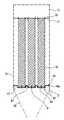
도 2 내지 도 4에서 나타낸 것과 같이, 본 발명의 일 실시예에 따른 여과집진장치는 상부 사각관체 구조의 본체(10)와 하부 원추형 구조의 호퍼(20)로 이루어지되, 상기 호퍼(20)의 하단부 일측에 함진가스가 유입되는 인입구(21)가 마련되고, 이 인입구(21)의 상방인 본체(10) 내부에 복수의 필터백(30)이 설치되며, 이 필터백(30)을 거친 여과가스가 외부로 배출되도록 본체(20)의 상단부에 배기구(12)가 형성되고, 상기 필터백(30)의 하단부인 본체(10)의 내부에 이 필터백(30)의 하단부를 고정시키기 위한 고정수단(40)이 마련되는 구성으로 되어 있다.As shown in Figure 2 to 4, the bag filter according to an embodiment of the present invention is composed of the
미 설명부호 14와 16은 각각 필터백(30)의 상단부를 고정시키기 위한 튜브시트와 스냅링을 나타낸 것이다.
상기 고정수단(40)은, 상기 각각의 필터백(30)의 저면을 떠받치는 저면받침부(41)와, 필터백(30)의 하단 외주면을 지지하는 외면지지부(42)로 이루어져 있다.The fixing means 40 is composed of a
여기서, 상기 저면받침부(41)는 교차되는 십자형 봉 구조로 되고, 이에 대응되는 외면지지부(42)는 상기 저면받침부(41)의 각 단부에서 상방으로 일정길이 직립 연장되는 일체형 구조로 되어 있다.Here, the
그리고, 상기 인접되는 각각의 외면지지부(42)를 서로 연결하는 연결바(43)가 더 구비되어 있다.In addition, a
그리고, 상기 본체(10)의 내면에 인접되는 각각의 외면지지부(42)에는 본체(10)의 내면과 연결 고정되도록 하는 연결고정바(44)가 더 구비되고, 이 연결고정바(44)의 본체(10) 내면을 향하는 단부는 이 본체(10) 내면과 평행하게 밀접된 상태로 고정되는 밀접부(44a)가 마련되어 있다.And, each of the outer
이러한 각각의 구성 요소가 서로 연결되어 원기둥 형상의 필터백(30) 하단부가 안착될 수 있도록 하는 복수의 포켓을 갖는 전체적인 구조의 고정수단을 완성하게 된다.Each of these components is connected to each other to complete the fixing means of the overall structure having a plurality of pockets to allow the bottom of the
이러한 구성에 따른 본 발명의 일 실시예인 여과집진장치는 필터백(30) 하단부가 위치하는 본체(10)의 내주면에 필터백(30) 고정수단(40)을 배치하되, 이 고정수단(40)의 각 밀접부(44a)가 본체(10)의 내면에 밀접된 상태로 고정되도록 하여 상기 고정수단(40)을 고정하고 나서, 각각의 필터백(30) 하단부가 포켓 형상의 저면받침부(41) 상에 안착되고 그 하단 테두리는 외면지지부(42)에 의해 지지되도록 한 상태에서 다시 필터백(30)의 상단부를 튜브시트(14)와 스냅링(16)을 이용하여 본체(10)의 상단부에 고정시켜 필터백(30) 고정작업을 완성한다.In one embodiment of the present invention the filter bag according to this configuration is disposed
이런 상태에서 인입구(21)를 통해 함진가스가 유입되면 상방의 필터백(30)으로 고르게 전달되어 분진의 여과가 이루어지게 되며 이렇게 필터백(30)을 통해 여과가 이루어진 여과가스는 본체(10) 상단부의 배기구(12)를 통해 외부로 배출되면서 본 발명의 여과집진장치를 통한 일 사이클의 여과작업이 완료되는 것이다.In this state, when the impregnated gas is introduced through the
도 1은 종래 기술의 여과집진장치를 나타낸 개략 단면도이다.1 is a schematic cross-sectional view showing a conventional bag filter.
도 2는 본 발명의 일 실시예에 따른 여과집진장치를 나타낸 개략 단면도이다.2 is a schematic cross-sectional view showing the bag filter according to an embodiment of the present invention.
도 3은 본 발명의 일 실시예에 따른 여과집진장치의 고정수단을 나타낸 사시도이다.3 is a perspective view showing the fixing means of the filter bag according to an embodiment of the present invention.
도 4는 본 발명의 일 실시예에 따른 여과집진장치의 고정수단에 필터백이 안착된 상태를 나타낸 저면 개략도이다.Figure 4 is a bottom plan view showing a state in which the filter bag is seated on the fixing means of the filter bag according to an embodiment of the present invention.
**도면의 주요부분에 대한 부호의 설명**DESCRIPTION OF REFERENCE NUMERALS
10 : 본체12 : 배기구10: main body 12: exhaust port
14 : 튜브시트16 : 스냅링14: tube sheet 16: snap ring
20 : 호퍼21 : 인입구20: Hopper 21: Inlet
30 : 필터백40 : 격판30: filter bag 40: diaphragm
41 : 저면받침부42 : 외면지지부41: bottom support 42: outer support
43 : 연결바44 : 연결고정바43: connection bar 44: connection fixing bar
44a : 밀접부44a: close part
Claims (6)
Translated fromKoreanPriority Applications (1)
| Application Number | Priority Date | Filing Date | Title |
|---|---|---|---|
| KR1020090050998AKR100973294B1 (en) | 2009-06-09 | 2009-06-09 | Dust collecting apparatus using filter bags |
Applications Claiming Priority (1)
| Application Number | Priority Date | Filing Date | Title |
|---|---|---|---|
| KR1020090050998AKR100973294B1 (en) | 2009-06-09 | 2009-06-09 | Dust collecting apparatus using filter bags |
Publications (1)
| Publication Number | Publication Date |
|---|---|
| KR100973294B1true KR100973294B1 (en) | 2010-07-30 |
Family
ID=42646193
Family Applications (1)
| Application Number | Title | Priority Date | Filing Date |
|---|---|---|---|
| KR1020090050998AActiveKR100973294B1 (en) | 2009-06-09 | 2009-06-09 | Dust collecting apparatus using filter bags |
Country Status (1)
| Country | Link |
|---|---|
| KR (1) | KR100973294B1 (en) |
Cited By (2)
| Publication number | Priority date | Publication date | Assignee | Title |
|---|---|---|---|---|
| KR20180131694A (en)* | 2017-05-31 | 2018-12-11 | 한국식품연구원 | Dust Collecting System |
| CN109847478A (en)* | 2019-03-22 | 2019-06-07 | 无锡红旗除尘设备有限公司 | A clustered modular filter bag assembly that can meet ultra-low emission requirements |
Citations (1)
| Publication number | Priority date | Publication date | Assignee | Title |
|---|---|---|---|---|
| JPS5592119A (en)* | 1978-12-28 | 1980-07-12 | Nitto Boseki Co Ltd | Bag filter pre-coating |
- 2009
- 2009-06-09KRKR1020090050998Apatent/KR100973294B1/enactiveActive
Patent Citations (1)
| Publication number | Priority date | Publication date | Assignee | Title |
|---|---|---|---|---|
| JPS5592119A (en)* | 1978-12-28 | 1980-07-12 | Nitto Boseki Co Ltd | Bag filter pre-coating |
Cited By (3)
| Publication number | Priority date | Publication date | Assignee | Title |
|---|---|---|---|---|
| KR20180131694A (en)* | 2017-05-31 | 2018-12-11 | 한국식품연구원 | Dust Collecting System |
| KR101980696B1 (en)* | 2017-05-31 | 2019-05-22 | 한국식품연구원 | Dust Collecting System |
| CN109847478A (en)* | 2019-03-22 | 2019-06-07 | 无锡红旗除尘设备有限公司 | A clustered modular filter bag assembly that can meet ultra-low emission requirements |
Similar Documents
| Publication | Publication Date | Title |
|---|---|---|
| KR100790334B1 (en) | Dust Bag Filter Bag | |
| US6706085B2 (en) | Filter bag cage | |
| US20130219842A1 (en) | Variable length bag cage | |
| KR100973294B1 (en) | Dust collecting apparatus using filter bags | |
| KR200446600Y1 (en) | Filter cage for dust collector and filter bag assembly comprising the same | |
| JP2009095721A (en) | Bug filter retainer | |
| KR20140121125A (en) | Bag Filter for Urtra Temperature | |
| US8500883B2 (en) | Apparatus and system for filtering air | |
| KR101522090B1 (en) | Filter bag having strap rino and fixing device thereof | |
| KR100893502B1 (en) | Filter bag cage | |
| CN205127573U (en) | Sack filter chamber of metal dust | |
| CN107376583B (en) | Flue gas purification reactor, cloth bag dust remover and dry type flue gas purification system | |
| KR200235249Y1 (en) | structure for mounting bag-filter of dust collector | |
| JP2011218292A (en) | Fine powder removal device | |
| CN211725037U (en) | Air inlet flow equalizing device of pulse dust removal filter bag dust remover | |
| CN210206226U (en) | Bag collector cage | |
| CN202191797U (en) | Pulse reverse-jet bag filter | |
| KR20170071035A (en) | Double filter, bringing Collection bag | |
| CN208865349U (en) | Weld fume purifier | |
| CN207838609U (en) | A kind of jig cleaner | |
| CN101934185A (en) | Built-in cyclone bag filter | |
| KR101120627B1 (en) | Cartridge-type dust collecting filter frame | |
| CN215782196U (en) | Bag type dust collector for fuming furnace | |
| KR20150020517A (en) | Filter bag having strap rino and fixing device thereof | |
| JP2005324144A (en) | Mounting structure and mounting method of cylindrical filter to dust collector |
Legal Events
| Date | Code | Title | Description |
|---|---|---|---|
| A201 | Request for examination | ||
| PA0109 | Patent application | St.27 status event code:A-0-1-A10-A12-nap-PA0109 | |
| PA0201 | Request for examination | St.27 status event code:A-1-2-D10-D11-exm-PA0201 | |
| A302 | Request for accelerated examination | ||
| PA0302 | Request for accelerated examination | St.27 status event code:A-1-2-D10-D17-exm-PA0302 St.27 status event code:A-1-2-D10-D16-exm-PA0302 | |
| D13-X000 | Search requested | St.27 status event code:A-1-2-D10-D13-srh-X000 | |
| D14-X000 | Search report completed | St.27 status event code:A-1-2-D10-D14-srh-X000 | |
| E902 | Notification of reason for refusal | ||
| PE0902 | Notice of grounds for rejection | St.27 status event code:A-1-2-D10-D21-exm-PE0902 | |
| T11-X000 | Administrative time limit extension requested | St.27 status event code:U-3-3-T10-T11-oth-X000 | |
| E13-X000 | Pre-grant limitation requested | St.27 status event code:A-2-3-E10-E13-lim-X000 | |
| P11-X000 | Amendment of application requested | St.27 status event code:A-2-2-P10-P11-nap-X000 | |
| P13-X000 | Application amended | St.27 status event code:A-2-2-P10-P13-nap-X000 | |
| E601 | Decision to refuse application | ||
| PE0601 | Decision on rejection of patent | St.27 status event code:N-2-6-B10-B15-exm-PE0601 | |
| J201 | Request for trial against refusal decision | ||
| PJ0201 | Trial against decision of rejection | St.27 status event code:A-3-3-V10-V11-apl-PJ0201 | |
| J301 | Trial decision | Free format text:TRIAL DECISION FOR APPEAL AGAINST DECISION TO DECLINE REFUSAL REQUESTED 20100202 Effective date:20100706 | |
| PJ1301 | Trial decision | St.27 status event code:A-3-3-V10-V15-crt-PJ1301 Decision date:20100706 Appeal event data comment text:Appeal Kind Category : Appeal against decision to decline refusal, Appeal Ground Text : 2009 0050998 Appeal request date:20100202 Appellate body name:Patent Examination Board Decision authority category:Office appeal board Decision identifier:2010101000794 | |
| PS0901 | Examination by remand of revocation | St.27 status event code:A-6-3-E10-E12-rex-PS0901 | |
| S901 | Examination by remand of revocation | ||
| GRNO | Decision to grant (after opposition) | ||
| GRNT | Written decision to grant | ||
| PR0701 | Registration of establishment | St.27 status event code:A-2-4-F10-F11-exm-PR0701 | |
| PS0701 | Decision of registration after remand of revocation | St.27 status event code:A-3-4-F10-F13-rex-PS0701 | |
| PR1002 | Payment of registration fee | St.27 status event code:A-2-2-U10-U11-oth-PR1002 Fee payment year number:1 | |
| PG1601 | Publication of registration | St.27 status event code:A-4-4-Q10-Q13-nap-PG1601 | |
| PN2301 | Change of applicant | St.27 status event code:A-5-5-R10-R13-asn-PN2301 St.27 status event code:A-5-5-R10-R11-asn-PN2301 | |
| FPAY | Annual fee payment | Payment date:20130725 Year of fee payment:4 | |
| PR1001 | Payment of annual fee | St.27 status event code:A-4-4-U10-U11-oth-PR1001 Fee payment year number:4 | |
| FPAY | Annual fee payment | Payment date:20140725 Year of fee payment:5 | |
| PR1001 | Payment of annual fee | St.27 status event code:A-4-4-U10-U11-oth-PR1001 Fee payment year number:5 | |
| FPAY | Annual fee payment | Payment date:20150722 Year of fee payment:6 | |
| PR1001 | Payment of annual fee | St.27 status event code:A-4-4-U10-U11-oth-PR1001 Fee payment year number:6 | |
| FPAY | Annual fee payment | Payment date:20160725 Year of fee payment:7 | |
| PR1001 | Payment of annual fee | St.27 status event code:A-4-4-U10-U11-oth-PR1001 Fee payment year number:7 | |
| P22-X000 | Classification modified | St.27 status event code:A-4-4-P10-P22-nap-X000 | |
| FPAY | Annual fee payment | Payment date:20170725 Year of fee payment:8 | |
| PR1001 | Payment of annual fee | St.27 status event code:A-4-4-U10-U11-oth-PR1001 Fee payment year number:8 | |
| FPAY | Annual fee payment | Payment date:20180725 Year of fee payment:9 | |
| PR1001 | Payment of annual fee | St.27 status event code:A-4-4-U10-U11-oth-PR1001 Fee payment year number:9 | |
| PR1001 | Payment of annual fee | St.27 status event code:A-4-4-U10-U11-oth-PR1001 Fee payment year number:10 | |
| PR1001 | Payment of annual fee | St.27 status event code:A-4-4-U10-U11-oth-PR1001 Fee payment year number:11 | |
| R18-X000 | Changes to party contact information recorded | St.27 status event code:A-5-5-R10-R18-oth-X000 | |
| PR1001 | Payment of annual fee | St.27 status event code:A-4-4-U10-U11-oth-PR1001 Fee payment year number:12 | |
| PR1001 | Payment of annual fee | St.27 status event code:A-4-4-U10-U11-oth-PR1001 Fee payment year number:13 | |
| R18-X000 | Changes to party contact information recorded | St.27 status event code:A-5-5-R10-R18-oth-X000 | |
| PR1001 | Payment of annual fee | St.27 status event code:A-4-4-U10-U11-oth-PR1001 Fee payment year number:14 | |
| PR1001 | Payment of annual fee | St.27 status event code:A-4-4-U10-U11-oth-PR1001 Fee payment year number:15 | |
| PR1001 | Payment of annual fee | St.27 status event code:A-4-4-U10-U11-oth-PR1001 Fee payment year number:16 |