Movatterモバイル変換


[0]ホーム

URL:


KR100970353B1 - Method and apparatus for channel and noise estimation - Google Patents

Method and apparatus for channel and noise estimation
Download PDF

Info

Publication number
KR100970353B1
KR100970353B1KR1020087012892AKR20087012892AKR100970353B1KR 100970353 B1KR100970353 B1KR 100970353B1KR 1020087012892 AKR1020087012892 AKR 1020087012892AKR 20087012892 AKR20087012892 AKR 20087012892AKR 100970353 B1KR100970353 B1KR 100970353B1
Authority
KR
South Korea
Prior art keywords
delete delete
noise
channel
samples
signal
Prior art date
Legal status (The legal status is an assumption and is not a legal conclusion. Google has not performed a legal analysis and makes no representation as to the accuracy of the status listed.)
Expired - Fee Related
Application number
KR1020087012892A
Other languages
Korean (ko)
Other versions
KR20080073307A (en
Inventor
김병훈
Original Assignee
퀄컴 인코포레이티드
Priority date (The priority date is an assumption and is not a legal conclusion. Google has not performed a legal analysis and makes no representation as to the accuracy of the date listed.)
Filing date
Publication date
Application filed by 퀄컴 인코포레이티드filedCritical퀄컴 인코포레이티드
Publication of KR20080073307ApublicationCriticalpatent/KR20080073307A/en
Application grantedgrantedCritical
Publication of KR100970353B1publicationCriticalpatent/KR100970353B1/en
Expired - Fee Relatedlegal-statusCriticalCurrent
Anticipated expirationlegal-statusCritical

Links

Images

Classifications

Landscapes

Abstract

Translated fromKorean

다수의 송신 안테나들로부터 다수의 수신 안테나들로 전송된 MIMO 송신에 대한 채널 및 잡음 추정을 수행하는 기술이 설명된다. 수신 안테나들로부터 샘플들이 획득된다. 제 1 방식에 있어서, 적어도 하나의 파일럿 시퀀스와 샘플들을 상관시킴으로써 채널 추정치들이 도출되고, 또한 이 샘플들에 기초하여 신호, 잡음 및 간섭 통계치들이 추정된다. 제 2 방식에 있어서, 샘플들에 기초하여 총 수신 에너지뿐만 아니라 신호 및 간섭 에너지가 추정된다. 그 다음에, 추정된 총 수신 에너지, 및 추정된 신호 및 간섭 에너지에 기초하여 잡음이 추정된다. 제 3 방식에 있어서, 샘플들에 기초하여 신호 및 온-타임 간섭 통계치들이 추정된다. 또한, 샘플들에 기초하여 잡음 및 다중경로 간섭 통계치들이 추정된다. 그 다음에 추정된 신호 및 온-타임 간섭 통계치들, 및 추정된 잡음 및 다중경로 간섭 통계치들에 기초하여 신호, 잡음 및 간섭 통계치들이 추정된다.Techniques for performing channel and noise estimation for MIMO transmissions transmitted from multiple transmit antennas to multiple receive antennas are described. Samples are obtained from the receive antennas. In a first scheme, channel estimates are derived by correlating samples with at least one pilot sequence, and signal, noise and interference statistics are also estimated based on these samples. In a second scheme, the signal and interference energy as well as the total received energy are estimated based on the samples. Then, noise is estimated based on the estimated total received energy and the estimated signal and interference energy. In a third scheme, signal and on-time interference statistics are estimated based on the samples. In addition, noise and multipath interference statistics are estimated based on the samples. The signal, noise and interference statistics are then estimated based on the estimated signal and on-time interference statistics and the estimated noise and multipath interference statistics.

MIMO 송신, 채널 추정, 잡음 추정, 다중경로, 백그라운드 잡음MIMO transmission, channel estimation, noise estimation, multipath, background noise

Description

Translated fromKorean
채널 및 잡음 추정을 위한 방법 및 장치{METHOD AND APPARATUS FOR CHANNEL AND NOISE ESTIMATION}METHOD AND APPARATUS FOR CHANNEL AND NOISE ESTIMATION

1. 35 U.S.C.§119 에 따른 우선권 주장1. Claims of priority under 35 U.S.C. §119

본 특허출원은, 본원의 양수인에게 양도되어 있고, 본 명세서에 참고로서 명백하게 통합되어 있으며, 2005년 10월 28일자로 출원된, 발명의 명칭이 "METHOD AND APPARATUS FOR SPACE-TIME EQUALIZATION WIRELESS COMMUNICATIONS" 인 미국 가출원 제 60/731,423 호에 대하여 우선권을 주장한다.This patent application is assigned to the assignee of the present application, is expressly incorporated herein by reference, and filed October 28, 2005, and entitled "METHOD AND APPARATUS FOR SPACE-TIME EQUALIZATION WIRELESS COMMUNICATIONS". Prioritizes US Provisional Application No. 60 / 731,423.

배경background

Ⅰ. 기술분야Ⅰ. Technical Field

본 개시물은 일반적으로 통신에 관한 것으로서, 더욱 상세하게는, MIMO (Multiple-Input Multiple-Output) 송신을 위해 채널 및 잡음 추정을 수행하는 기술에 관한 것이다.TECHNICAL FIELD This disclosure relates generally to communications and, more particularly, to techniques for performing channel and noise estimation for multiple-input multiple-output (MIMO) transmission.

Ⅱ. 배경기술II. Background

MIMO 송신은, 다수의 (T 개의) 송신 안테나들로부터 다수의 (R 개의) 수신 안테나들로의 송신이다. 예를 들어, 송신기는 T 개의 송신 안테나들로부터 T 개의 데이터 스트림을 동시에 송신할 수도 있다. 이들 데이터 스트림은, 전파 환경에 의해 왜곡되고, 잡음에 의해 추가적으로 열화된다. 수신기는 R 개의 수신 안테나를 통해 송신된 데이터 스트림을 수신한다. 각각의 안테나로부터 수신된 신호는, 가능하게는 전파 환경에 의해 결정된 상이한 지연으로 송신된 데이터 스트림의 스케일링된 버전을 포함한다. 따라서, 송신된 데이터 스트림은, R 개의 수신 안테나들로부터의 R 개의 수신된 신호들 사이에서 분산된다. 이어서, 수신기는, 송신된 데이터 스트림을 복구하기 위해서, R 개의 수신된 신호에 대한 수신기 공간 처리 (예를 들어, 공간-시간 등화 (equalization)) 를 수행한다.MIMO transmission is transmission from multiple (T) transmit antennas to multiple (R) receive antennas. For example, the transmitter may transmit T data streams simultaneously from the T transmit antennas. These data streams are distorted by the propagation environment and further degraded by noise. The receiver receives data streams transmitted through the R receive antennas. The signal received from each antenna includes a scaled version of the data stream transmitted, possibly with a different delay determined by the propagation environment. Thus, the transmitted data stream is distributed among the R received signals from the R receive antennas. The receiver then performs receiver spatial processing (eg, space-time equalization) on the R received signals to recover the transmitted data stream.

수신기는, MIMO 채널에 대한 채널과 잡음 추정치를 유도할 수도 있고, 이어서, 이 채널과 잡음 추정치에 기초하여 공간-시간 등화기에 대한 가중치를 유도할 수도 있다. 채널 및 잡음 추정치의 품질은 성능에 큰 영향을 줄 수도 있다. 그러므로, 본 발명이 속하는 기술분야에서 MIMO 송신에 대한 채널 및 잡음 추정치의 품질을 유도할 필요가 있다.The receiver may derive a channel and noise estimate for the MIMO channel and then derive weights for the space-time equalizer based on the channel and noise estimate. The quality of the channel and noise estimates can have a significant impact on performance. Therefore, there is a need in the art to derive the quality of channel and noise estimates for MIMO transmissions.

개요summary

본 발명의 일 실시형태에 따르면, 적어도 하나의 프로세서와 메모리를 포함하는 장치가 기재된다. 프로세서(들)는, 다수의 송신 안테나들로부터 전송된 MIMO 송신에 대한 다수의 수신 안테나들로부터의 샘플을 획득하고, 적어도 하나의 파일럿 시퀀스와 이 샘플들을 상관시킴으로써 채널 추정치를 도출하고, 이 샘플들에 기초하여 신호, 잡음과 간섭 통계치를 추정한다. MIMO 송신은 다수의 송신 안테나들로부터 전송된 다중 변조된 신호들을 포함할 수도 있다. 각각의 변조 된 신호는, 상이한 직교 코드로 다중화된 다중 데이터 스트림들을 포함할 수도 있다.According to one embodiment of the invention, an apparatus comprising at least one processor and a memory is described. The processor (s) obtains samples from multiple receive antennas for MIMO transmissions transmitted from multiple transmit antennas, derives channel estimates by correlating these samples with at least one pilot sequence, and the samples Estimate the signal, noise and interference statistics based on. MIMO transmission may include multiple modulated signals transmitted from multiple transmit antennas. Each modulated signal may include multiple data streams multiplexed with different orthogonal codes.

다른 실시형태에 따르면, 적어도 하나의 프로세서와 메모리를 포함하는 장치가 기재된다. 프로세서(들)는, 다수의 송신 안테나들로부터 전송된 MIMO 송신에 대한 다수의 수신 안테나들로부터의 샘플들을 획득하고, 이 샘플들에 기초하여 총 수신 에너지를 추정하고, 추정된 총 수신 에너지, 및 추정된 신호와 간섭 에너지에 기초하여 잡음을 추정한다.According to another embodiment, an apparatus comprising at least one processor and a memory is described. The processor (s) obtains samples from multiple receive antennas for MIMO transmissions transmitted from multiple transmit antennas, estimates the total received energy based on the samples, estimates the total received energy, and Noise is estimated based on the estimated signal and the interference energy.

또 다른 실시형태에 따르면, 적어도 하나의 프로세서와 메모리를 포함하는 장치가 기재된다. 프로세서(들)는, 다수의 송신 안테나들로부터 전송된 MIMO 송신에 대한 다수의 수신 안테나들로부터의 샘플들을 획득하고, 이 샘플들에 기초하여 신호와 온-타임 간섭 통계치를 추정하고, 이 샘플들에 기초하여 잡음과 다중경로 간섭 통계치를 추정하고, 이 추정된 신호와 온-타임 간섭 통계치, 및 추정된 잡음과 다중경로 간섭 통계치에 기초하여 신호, 잡음, 및 간섭 통계치를 추정한다. 온-타임 간섭은, 원하는 신호와 동일한 시간에 도착하는 간섭이고, 다중경로 간섭은 온-타임이 아닌 간섭이다.According to yet another embodiment, an apparatus comprising at least one processor and a memory is described. The processor (s) obtain samples from multiple receive antennas for MIMO transmissions transmitted from multiple transmit antennas, estimate signals and on-time interference statistics based on these samples, and Estimate noise and multipath interference statistics based on the estimated signal and on-time interference statistics, and estimate the signal, noise, and interference statistics based on the estimated noise and multipath interference statistics. On-time interference is interference that arrives at the same time as the desired signal, and multipath interference is interference that is not on-time.

또 다른 실시형태에 따르면, 적어도 하나의 프로세서와 메모리를 포함하는 장치가 기재된다. 프로세서(들)는, 다수의 송신 안테나들로부터 전송된 MIMO 송신에 대한 다수의 수신 안테나들로부터의 샘플들을 획득하고, 이 샘플들에 기초하여 채널 상태를 결정하고, 채널 상태에 기초하여 다중 채널과 잡음 추정 방식 중 하나를 선택하고, 이 선택된 채널과 잡음 추정 방식에 기초하여 채널과 잡음 추정 을 수행한다. 채널 상태를 결정하기 위해서, 프로세서(들)는, 지연 확산을 결정하고, 이 샘플들을 처리하여 단일 경로 또는 다중경로 환경 등을 식별할 수도 있다.According to yet another embodiment, an apparatus comprising at least one processor and a memory is described. The processor (s) obtains samples from multiple receive antennas for MIMO transmissions transmitted from multiple transmit antennas, determines a channel state based on the samples, and determines a multi-channel and Select one of the noise estimation methods and perform channel and noise estimation based on this selected channel and noise estimation method. To determine the channel state, the processor (s) may determine delay spread and process these samples to identify a single path or multipath environment, and the like.

이하, 본 발명의 다양한 양태 및 실시형태들이 더욱 상세하게 기술된다.Hereinafter, various aspects and embodiments of the invention are described in more detail.

도면의 간단한 설명Brief description of the drawings

도 1 은 MIMO 송신을 위한 송신기 및 수신기를 나타낸다.1 shows a transmitter and a receiver for MIMO transmission.

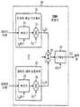
도 2 는 하나의 송신 안테나에 대한 CDMA 변조기를 나타낸다.2 shows a CDMA modulator for one transmit antenna.

도 3 은 제 1 방식을 위한 채널 및 잡음 추정기를 나타낸다.3 shows a channel and noise estimator for the first scheme.

도 4 는 채널 추정기를 나타낸다4 shows a channel estimator

도 5 는 제 1 채널 및 잡음 추정 방식을 위한 프로세스를 나타낸다.5 shows a process for the first channel and noise estimation scheme.

도 6 은 제 2 방식을 위한 채널 및 잡음 추정기를 나타낸다6 shows a channel and noise estimator for a second scheme;

도 7 은 제 2 채널 및 잡음 추정 방식을 위한 프로세스를 나타낸다.7 shows a process for the second channel and noise estimation scheme.

도 8 은 제 3 방식을 위한 채널 및 잡음 추정기를 나타낸다.8 shows a channel and noise estimator for a third scheme.

도 9 는 제 3 채널 및 잡음 추정 방식을 위한 프로세스를 나타낸다.9 shows a process for the third channel and noise estimation scheme.

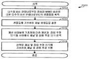
도 10 은 제 4 채널 및 잡음 추정 방식을 위한 프로세스를 나타낸다10 shows a process for a fourth channel and noise estimation scheme

상세한 설명details

본 명세서에서, "예시적인" 이라는 용어는 "실시예, 사례, 또는 예시의 역할을 하는 것" 을 의미하는데 이용된다. 본 명세서에서, "예시적인" 으로 기술된 임의의 실시형태는 다른 실시형태들보다 바람직하거나 이점이 있는 것으로 반드시 구성되는 것은 아니다.As used herein, the term "exemplary" is used to mean "acting as an embodiment, example, or illustration." In this specification, any embodiment described as "exemplary" is not necessarily configured to be preferred or advantageous over other embodiments.

본 명세서에 기재된, 채널 및 잡음 추정 기술은, 코드 분할 다중 접속 (CDMA) 시스템, 시분할 다중 접속 (TDMA) 시스템, 주파수 분할 다중 접속 (FDMA) 시스템, 직교 FDMA (OFDMA) 시스템, 단일-캐리어 FDMA (SC-FDMA) 시스템 등과 같은 다양한 통신 시스템에 이용될 수도 있다. CDMA 시스템은, 광대역-CDMA (W-CDMA), cdma2000 등과 같은 하나 이상의 무선 기술을 구현할 수도 있다. cdma2000 은 IS-2000, IS-856, 및 IS-95 표준을 커버한다. TDMA 시스템은, GSM (Global System for Mobile Communications) 과 같은 무선 기술을 구현할 수도 있다. 이들 다양한 무선 기술과 표준은 본 발명이 속하는 기술분야에서 공지되어 있다. W-CDMA 및 GSM 은 "3 세대 파트너쉽 프로젝트 (3GPP)" 로 명명된 단체로부터의 문서에 기술되어 있다. cdma2000 은 "3 세대 파트너쉽 프로젝트 2 (3GPP2)" 로 명명된 단체로부터의 문서에 기술되어 있다. 3GPP 및 3GPP2 문서들은 공개적으로 입수 가능하다. OFDMA 시스템은, 직교 주파수 분할 다중화 (OFDM) 를 이용하여 직교 주파수 서브캐리어를 통해 주파수 도메인에서 변조 심볼을 송신한다. SC-FDMA 시스템은, 직교 주파수 서브캐리어를 통해 시간 도메인에서 변조 심볼을 송신한다. 명확함을 위해서, 이하, 이들 기술은 W-CDMA 및/또는 cdma2000 을 구현할 수도 있는 CDMA 시스템에서 전송된 MIMO 송신에 대해 후술된다.The channel and noise estimation techniques described herein include code division multiple access (CDMA) systems, time division multiple access (TDMA) systems, frequency division multiple access (FDMA) systems, orthogonal FDMA (OFDMA) systems, single-carrier FDMA ( It may be used in various communication systems such as SC-FDMA) system. The CDMA system may implement one or more wireless technologies, such as wideband-CDMA (W-CDMA), cdma2000, and the like. cdma2000 covers IS-2000, IS-856, and IS-95 standards. The TDMA system may implement a radio technology such as Global System for Mobile Communications (GSM). These various radio technologies and standards are known in the art. W-CDMA and GSM are described in a document from an organization named "3rd Generation Partnership Project (3GPP)". cdma2000 is described in a document from an organization named "3rd Generation Partnership Project 2 (3GPP2)". 3GPP and 3GPP2 documents are publicly available. An OFDMA system transmits modulation symbols in the frequency domain on an orthogonal frequency subcarrier using orthogonal frequency division multiplexing (OFDM). The SC-FDMA system transmits modulation symbols in the time domain on orthogonal frequency subcarriers. For clarity, these techniques are described below for MIMO transmissions transmitted in a CDMA system that may implement W-CDMA and / or cdma2000.

도 1 은 MIMO 송신을 위한 송신기 (110) 와 수신기 (150) 의 블록도이다. 다운링크/순방향 링크 송신에 있어서, 송신기 (110) 는 기지국의 일부이고, 수신 기 (150) 는 무선 디바이스의 일부이다. 업링크/역방향 링크 송신에 있어서, 송신기 (110) 는 무선 디바이스의 일부이고, 수신기 (150) 는 기지국의 일부이다. 통상적으로, 기지국은 무선 디바이스와 통신하는 고정국이고, 또한, 노드 B, 액세스 포인트 등으로 지칭될 수도 있다. 무선 디바이스는 고정형, 또는 이동형일 수도 있고, 또한 사용자 장비 (UE), 이동국, 사용자 단말기, 가입자 유닛 등으로 지칭될 수도 있다. 무선 디바이스는 셀룰러 전화기, 개인 휴대 정보 단말기 (PDA), 무선 모뎀 카드, 또는 일부 다른 디바이스 또는 장치일 수도 있다.1 is a block diagram of atransmitter 110 and areceiver 150 for MIMO transmission. For downlink / forward link transmissions,transmitter 110 is part of a base station andreceiver 150 is part of a wireless device. For uplink / reverse link transmission,transmitter 110 is part of a wireless device andreceiver 150 is part of a base station. Typically, a base station is a fixed station that communicates with a wireless device and may also be referred to as a Node B, an access point, or the like. The wireless device may be fixed or mobile and may also be referred to as a user equipment (UE), a mobile station, a user terminal, a subscriber unit, or the like. The wireless device may be a cellular telephone, a personal digital assistant (PDA), a wireless modem card, or some other device or device.

송신기 (110) 에서, 송신 (TX) 데이터 프로세서 (120) 는, 트래픽 데이터를 처리 (예를 들어, 인코딩, 인터리빙, 및 심볼 매핑) 하여, 다수의 (T 개의) CDMA 변조기 (130a 내지 130t) 로 데이터 심볼을 제공한다. 본 명세서에 이용된 바와 같이, 데이터 심볼은 데이터에 대한 변조 심볼이고, 파일럿 심볼은 파일럿에 대한 변조 심볼이고, 변조 심볼은 (예를 들어, M-PSK 또는 M-QAM 에 있어서) 단일 콘스텔레이션 (constellation) 에서의 일 포인트에 대한 복소수 값이고, 파일럿은 송신기와 수신기 모두에 의해 선험적으로 (a priori) 공지된 데이터이다. 각각의 CDMA 변조기 (130) 는, 후술되는 바와 같이 그 데이터 심볼과 파일럿 심볼을 처리하고, 연관된 송신기 유닛 (TMTR; 136) 으로 출력 칩을 제공한다. 각각의 송신기 유닛 (136) 은, 그 출력 칩을 처리 (예를 들어, 아날로그로 변환, 증폭, 필터링, 및 주파수 상향변환) 하여, 변조된 신호를 발생시킨다. T 개의 송신기 유닛들 (136a 내지 136t) 로부터의 T 개의 변조된 신호들은 각각 T 개의 안테나들 (138a 내지 138t) 로부터 송신된다.Attransmitter 110, transmit (TX)data processor 120 processes (e.g., encodes, interleaves, and symbol maps) the traffic data to multiple (T)CDMA modulators 130a through 130t. Provide data symbols. As used herein, a data symbol is a modulation symbol for data, a pilot symbol is a modulation symbol for a pilot, and the modulation symbol is a single constellation (eg, for M-PSK or M-QAM). It is a complex value for one point in constellation, and the pilot is data knowna priori by both the transmitter and the receiver. Each CDMA modulator 130 processes its data symbols and pilot symbols as described below and provides an output chip to an associated transmitter unit (TMTR) 136. Each transmitter unit 136 processes (eg, converts to analog, amplifies, filters, and frequency upconverts) its output chip to generate a modulated signal. T modulated signals fromT transmitter units 136a through 136t are transmitted fromT antennas 138a through 138t, respectively.

수신기 (150) 에서, 다수의 (R 개의) 안테나들 (152a 내지 152r) 은, 다양한 신호 경로들을 통해 송신된 신호를 수신하고, 각각 R 개의 수신기 유닛들 (RCVR; 154a 내지 154r) 로 R 개의 수신 신호를 제공한다. 각각의 수신기 유닛 (154) 은, 그 수신 신호를 처리 (예를 들어, 필터링, 증폭, 주파수 하향변환, 및 디지털화) 하여, 샘플을 채널 및 잡음 추정기 (160) 와, 공간-시간 등화기 (162) 로 제공한다. 후술되는 바와 같이, 추정기 (160) 는 이 샘플들에 기초하여 채널 및 잡음 추정치를 도출한다. 공간-시간 등화기 (162) 는, 채널 및 잡음 추정치에 기초하여 가중치를 도출하고, 이 가중치로 샘플에 대해 등화를 수행하고, T 개의 CDMA 복조기 (Demodulator; 170a 내지 170t) 로 데이터 칩 추정치를 제공한다. 각각의 CDMA 복조기 (170) 는, CDMA 변조기 (130) 에 의한 프로세싱에 상보적인 방식으로 그 데이터 칩 추정치를 처리하고, 데이터 심볼 추정치를 제공한다. 수신 (RX) 데이터 프로세서 (180) 는, 데이터 심볼 추정치를 처리 (예를 들어, 심볼 디매핑, 디인터리빙, 및 디코딩) 하여, 디코딩된 데이터를 제공한다. 일반적으로, CDMA 복조기 (170) 와 RX 데이터 프로세서 (180) 에 의한 프로세싱은, 송신기 (110) 에서의 CDMA 변조기 (130) 와 TX 데이터 프로세서 (120) 에 의한 프로세싱에 각각 상보적이다.Inreceiver 150, multiple (R)antennas 152a through 152r receive a signal transmitted over the various signal paths, each receiving R through R receiver units (RCVR) 154a through 154r. Provide a signal. Each receiver unit 154 processes (eg, filters, amplifies, frequency downconverts, and digitizes) the received signal to channel the sample to a channel andnoise estimator 160 and a space-time equalizer 162. ) As described below,estimator 160 derives a channel and noise estimate based on these samples. Spatial-time equalizer 162 derives weights based on channel and noise estimates, performs equalization on the samples with these weights, and provides data chip estimates to T CDMA demodulators 170a to 170t. do. Each CDMA demodulator 170 processes its data chip estimates in a manner complementary to processing by the CDMA modulator 130 and provides data symbol estimates. The receive (RX)data processor 180 processes (eg, symbol demaps, deinterleaves, and decodes) the data symbol estimates to provide decoded data. In general, the processing by the CDMA demodulator 170 and theRX data processor 180 is complementary to the processing by the CDMA modulator 130 and theTX data processor 120 at thetransmitter 110, respectively.

제어기/프로세서 (140 및 190) 는 각각 송신기 (110), 및 수신기 (150) 에서의 다양한 프로세싱 유닛의 동작을 지시한다. 메모리 (142 및 192) 각각은, 송신기 (110) 및 수신기 (150) 에 대한 데이터와 프로그램 코드를 저장한다.Controller /processors 140 and 190 direct the operation of various processing units attransmitter 110 andreceiver 150, respectively. Each of thememories 142 and 192 stores data and program codes for thetransmitter 110 and thereceiver 150.

도 2 는 하나의 송신 안테나에 대한 CDMA 변조기 (130) 의 블록도이다. CDMA 변조기 (130) 는, 도 1 에서 CDMA 변조기들 (130a 내지 130t) 각각에 이용될 수도 있다. CDMA 변조기 (130) 는, 트래픽 데이터를 위해 이용되는 각각의 트래픽 채널에 대한 트래픽 채널 프로세서 (210) 와, 파일럿에 대한 파일럿 채널 프로세서 (220) 를 포함한다. 트래픽 채널 (m) 에 대한 프로세서 (210) 내에서, 확산기 (212) 는 트래픽 채널 (m) 에 대한 직교 코드

Figure 112008038371015-pct00001
로 데이터 심볼을 확산시킨다. 다중화기 (214) 는 이득
Figure 112008038371015-pct00002
으로 확산기 (212) 의 출력을 스케일링하고, 송신 안테나 (t) 를 통해 트래픽 채널 (m) 에 대한 데이터 칩
Figure 112008038371015-pct00003
을 제공한다. 파일럿 채널 프로세서 (220) 내에서, 확산기 (222) 는, 파일럿에 대한 직교 코드
Figure 112008038371015-pct00004
로 파일럿 심볼을 확산시킨다. 다중화기 (224) 는 이득
Figure 112008038371015-pct00005
으로 확산기 (222) 의 출력을 스케일링하고, 송신 안테나 (t) 를 통해 파일럿 채널에 대한 파일럿 칩
Figure 112008038371015-pct00006
을 제공한다. 합산기 (230) 는 모든 트래픽 채널과 파일럿 채널에 대한 칩들을 합산한다. 스크램블러 (232) 는, 송신기 (110) 에 대해 스크램블링 시퀀스
Figure 112008038371015-pct00007
와 합산기 (230) 의 출력을 승산하고, 송신 안테나 (t) 에 대한 출력 칩
Figure 112008038371015-pct00008
을 제공한다.2 is a block diagram of a CDMA modulator 130 for one transmit antenna. CDMA modulator 130 may be used for each ofCDMA modulators 130a through 130t in FIG. 1. CDMA modulator 130 includes atraffic channel processor 210 for each traffic channel used for traffic data and apilot channel processor 220 for the pilot. Withinprocessor 210 for traffic channel m,spreader 212 is orthogonal code for traffic channel m.
Figure 112008038371015-pct00001
Spreads the data symbols.Multiplexer 214 gains
Figure 112008038371015-pct00002
And scale the output ofspreader 212 and transmit data chip for traffic channel m through transmit antenna t.
Figure 112008038371015-pct00003
To provide. Withinpilot channel processor 220,spreader 222 is orthogonal code for pilot
Figure 112008038371015-pct00004
Spreads the pilot symbols.Multiplexer 224 gains
Figure 112008038371015-pct00005
And scale the output ofspreader 222 through a transmit antenna t for the pilot chip for the pilot channel.
Figure 112008038371015-pct00006
To provide.Summer 230 sums the chips for all traffic channels and pilot channels. Thescrambler 232 performs a scrambling sequence for thetransmitter 110.
Figure 112008038371015-pct00007
Multiplying the output ofsummer 230 with the output chip for the transmit antenna t
Figure 112008038371015-pct00008
To provide.

트래픽 채널과 파일럿 채널을 위한 직교 코드는, W-CDMA 에서 이용된 직교 가변 확산 인자 (OVSF) 코드, cdma2000 에서 이용된 월시 코드 등일 수도 있다. 일 실시형태에서, T 개의 상이한 직교 코드는, T 개의 송신 안테나에 대한 파일럿에 이용되어, 수신기 (150) 가 각각의 송신 안테나에 대한 채널 응답을 추정하는 것을 가능하게 한다. 잔여 직교 코드들은 T 개의 송신 안테나들 각각에 이용될 수도 있다. 본 실시형태에서, T 개의 송신 안테나들에 대한 파일럿 직교 코드는 상이한 반면에, 트래픽 직교 코드는 T 개의 송신 안테나들을 위해 재사용될 수도 있다. 또한, 확산 및 스크램블링이 도 2 에 도시된 방식과는 다른 방식으로 수행될 수도 있다.The orthogonal codes for the traffic channel and the pilot channel may be an orthogonal variable spreading factor (OVSF) code used in W-CDMA, a Walsh code used in cdma2000, and the like. In one embodiment, T different orthogonal codes are used for pilot for the T transmit antennas, allowing thereceiver 150 to estimate the channel response for each transmit antenna. Residual orthogonal codes may be used for each of the T transmit antennas. In this embodiment, the pilot orthogonal code for the T transmit antennas is different, while the traffic orthogonal code may be reused for the T transmit antennas. Also, diffusion and scrambling may be performed in a manner different from that shown in FIG.

각각의 송신 안테나 (t) 에 대한 출력 칩은 다음으로 표현될 수도 있다:The output chip for each transmit antenna t may be represented as:

Figure 112008038371015-pct00009

여기서,

Figure 112008038371015-pct00010
은, 송신 안테나 (t) 로부터 전송된
Figure 112008038371015-pct00011
개의 출력 칩을 갖는
Figure 112008038371015-pct00012
벡터이고,
Figure 112008038371015-pct00013
은, 송신 안테나 (t) 로부터 칩 주기
Figure 112008038371015-pct00014
내로 전송된 출력 칩이고,
Figure 112008038371015-pct00015
는 출력 칩에 대한 이득이고,"T" 는 전치 행렬을 가리킨다.here,
Figure 112008038371015-pct00010
Is transmitted from the transmit antenna (t)
Figure 112008038371015-pct00011
Output chips
Figure 112008038371015-pct00012
Vector,
Figure 112008038371015-pct00013
Is the chip period from the transmit antenna (t)
Figure 112008038371015-pct00014
Is an output chip sent into
Figure 112008038371015-pct00015
Is the gain for the output chip and" T " indicates the transpose matrix.

K 는

Figure 112008038371015-pct00016
로서 설정될 수도 있고, 여기서 E 는 수신기 (150) 에서의 공간-시간 등화기 (162) 의 범위 (span) 이고, L 은 송신기 (110) 와 수신기 (150) 사이의 MIMO 채널의 지연 확산이다. 다음으로, 벡터
Figure 112008038371015-pct00017
는, 수신기에서 공간-시간 등화기에서 동작될
Figure 112008038371015-pct00018
개의 칩을 포함한다.K is
Figure 112008038371015-pct00016
It may be set as, where E is the span of the space-time equalizer 162 at thereceiver 150, and L is the delay spread of the MIMO channel between thetransmitter 110 and thereceiver 150. Next, vector
Figure 112008038371015-pct00017
Be operated on a space-time equalizer at the receiver
Figure 112008038371015-pct00018
Chips.

일 실시형태에서, 수신기는, V 의 오버샘플링 인자에 대한 칩 레이트의 V 배로, 각각의 수신 안테나로부터 수신된 신호를 디지털화하고, 각각의 칩 주기 동안 V 샘플들을 획득한다. 각각의 수신 안테나 (r) 에 대한 샘플은 다음으로 표현 될 수도 있다:In one embodiment, the receiver digitizes the signal received from each receive antenna at V times the chip rate for the oversampling factor of V and obtains V samples for each chip period. The sample for each receive antenna r may be represented as:

Figure 112008038371015-pct00019

여기서,

Figure 112008038371015-pct00020
은 수신 안테나 (r) 에 대한 샘플의
Figure 112008038371015-pct00021
벡터이고,
Figure 112008038371015-pct00022
은 수신 안테나 (r) 에 대한 칩 주기
Figure 112008038371015-pct00023
에서의 v 번째 샘플이다.here,
Figure 112008038371015-pct00020
Of the sample for the receiving antenna (r)
Figure 112008038371015-pct00021
Vector,
Figure 112008038371015-pct00022
Is the chip period for the receive antenna (r)
Figure 112008038371015-pct00023
The v th sample in.

Figure 112008038371015-pct00024
에서의 샘플에 의해 관찰된 잡음은 다음으로 표현될 수도 있다:
Figure 112008038371015-pct00024
The noise observed by the sample at may be expressed as:

Figure 112008038371015-pct00025

여기서,

Figure 112008038371015-pct00026
은 수신 안테나 (r) 에 대한
Figure 112008038371015-pct00027
잡음 벡터이고,
Figure 112008038371015-pct00028
Figure 112008038371015-pct00029
에 의해 관찰되는 잡음이다.here,
Figure 112008038371015-pct00026
For the receiving antenna (r)
Figure 112008038371015-pct00027
Is a noise vector,
Figure 112008038371015-pct00028
silver
Figure 112008038371015-pct00029
Is the noise observed by.

Figure 112008038371015-pct00030
은, 채널 잡음, 수신기 잡음, 및 다른 송신기들로부터의 간섭을 포함하는데, 이는 "백그라운드" 잡음으로서 집합적으로 언급된다. 본 명세서에 이용되는 바와 같이, "잡음" 이란 용어는, 단지 백그라운드 잡음, 또는 다른 송신 안테나들로부터의 백그라운드 잡음과 인터-스트림 간섭으로 언급될 수도 있다. 예를 들어, 채널 및 잡음 추정은, 채널 추정과, 백그라운드 잡음 추정 또는 백그라운드 잡음 및 간섭 추정 중 하나로 언급될 수도 있다.
Figure 112008038371015-pct00030
Includes channel noise, receiver noise, and interference from other transmitters, which are collectively referred to as "background" noise. As used herein, the term “noise” may only be referred to as background noise, or inter-stream interference with background noise from other transmit antennas. For example, channel and noise estimation may be referred to as either channel estimation and background noise estimation or background noise and interference estimation.

모든 R 개의 수신 안테나들에 대한 샘플들은 다음으로 표현될 수도 있다:Samples for all R receive antennas may be represented as:

Figure 112008038371015-pct00031

여기서,

Figure 112008038371015-pct00032
은, 송신 안테나 (t) 및 수신 안테나 (r) 사이의
Figure 112008038371015-pct00033
다중경로 채널 행렬이다.
Figure 112008038371015-pct00034
은 다음으로 주어질 수도 있다:here,
Figure 112008038371015-pct00032
Is between the transmitting antenna (t) and the receiving antenna (r).
Figure 112008038371015-pct00033
It is a multipath channel matrix.
Figure 112008038371015-pct00034
Can also be given by:

Figure 112008038371015-pct00035

여기서,

Figure 112008038371015-pct00036
은,v 번째 샘플링 시간 인스턴트에서의l 번째 채널 탭에 대한 송신 안테나 (t) 와 수신 안테나 (r) 사이의 복소수 채널 이득이다.here,
Figure 112008038371015-pct00036
Is the complex channel gain between transmit antennat and receive antennar for thel- th channel tap at thev- th sampling time instant.

송신 안테나 (t) 와 수신 안테나 (r) 사이의 임펄스 응답은 L 칩 길이를 갖고, V·L 채널 이득을 획득하기 위해서 V 배의 칩 레이트로 오버샘플링될 수도 있다. 이들 V·L 채널 이득은 V 행으로 배열될 수도 있어서, 각각의 행은 하나의 샘플링 시간 인스턴트 (v) 에 대한 L 개의 채널 이득을 포함한다. 샘플링 시간 인스턴트 (v) 에 대한 샘플

Figure 112008038371015-pct00037
는, 그 샘플링 시간 인스턴트에 대한 채널 이득의 행과
Figure 112008038371015-pct00038
에서의 송신 데이터 칩들을 콘볼루션함으로써 획득된다.
Figure 112008038371015-pct00039
Figure 112008038371015-pct00040
에서의 V·E 샘플에 대한 V·E 행을 포함한다.
Figure 112008038371015-pct00041
의 각각의 행 은,
Figure 112008038371015-pct00042
에서의 하나의 샘플에 대한 채널 임펄스 응답을 나타낸다.The impulse response between the transmit antennat and the receive antennar has an L chip length and may be oversampled at V times the chip rate to obtain a V-L channel gain. These V-L channel gains may be arranged in V rows, each row containing L channel gains for one sampling time instant (v). Sample for sampling time instant (v)
Figure 112008038371015-pct00037
, With a row of channel gain for that sampling time instant
Figure 112008038371015-pct00038
Obtained by convolving transmit data chips at < RTI ID = 0.0 >
Figure 112008038371015-pct00039
Is
Figure 112008038371015-pct00040
Contains the V · E row for the V · E sample in.
Figure 112008038371015-pct00041
Each row of
Figure 112008038371015-pct00042
Represents the channel impulse response for one sample in.

수학식 4 는 다음으로 재표기될 수도 있다:Equation 4 may be rewritten as:

Figure 112008038371015-pct00043

여기서,

Figure 112008038371015-pct00044
은, 모든 R 개의 수신 안테나들에 대한
Figure 112008038371015-pct00045
전체 수신 샘플 벡터이고,
Figure 112008038371015-pct00046
은, 모든 T 개의 송신 안테나들에 대한
Figure 112008038371015-pct00047
전체 송신 칩 벡터이고,
Figure 112008038371015-pct00048
은, 모든 R 개의 수신 안테나에 대한
Figure 112008038371015-pct00049
전체 잡음 벡터이고,
Figure 112008038371015-pct00050
Figure 112008038371015-pct00051
전체 채널 응답 행렬이다.here,
Figure 112008038371015-pct00044
For all R receive antennas
Figure 112008038371015-pct00045
Is the entire received sample vector,
Figure 112008038371015-pct00046
Is for all T transmit antennas
Figure 112008038371015-pct00047
Is the entire transmit chip vector,
Figure 112008038371015-pct00048
For all R receive antennas
Figure 112008038371015-pct00049
Is the overall noise vector,
Figure 112008038371015-pct00050
silver
Figure 112008038371015-pct00051
The full channel response matrix.

전체 채널 응답 행렬

Figure 112008038371015-pct00052
은 다음으로 주어질 수도 있다:Full channel response matrix
Figure 112008038371015-pct00052
Can also be given by:

Figure 112008038371015-pct00053

Figure 112008038371015-pct00054
의 첫번째 K 열은 송신 안테나 1 에 대한 것이고,
Figure 112008038371015-pct00055
의 다음의 K 열은 송신 안테나 2 에 대한 것이고, …,
Figure 112008038371015-pct00056
의 마지막 K 열은 송신 안테나 T 에 대한 것이다.
Figure 112008038371015-pct00057
의 각각의 열은
Figure 112008038371015-pct00058
로서 표시되고, 하나의 송신 칩
Figure 112008038371015-pct00059
에 의해 관찰된 채널 이득을 포함한다.
Figure 112008038371015-pct00054
The first K columns of are for transmitantenna 1,
Figure 112008038371015-pct00055
The next K column of is for transmitantenna 2,. ,
Figure 112008038371015-pct00056
The last K column of is for the transmit antenna T.
Figure 112008038371015-pct00057
Each column of
Figure 112008038371015-pct00058
As one transmit chip
Figure 112008038371015-pct00059
It includes the channel gain observed by.

송신 칩들은 공간-시간 등화기 (162) 에 의해 다음으로 복구될 수도 있다:The transmit chips may be recovered by space-time equalizer 162 to:

Figure 112008038371015-pct00060

여기서,

Figure 112008038371015-pct00061
은, 송신 안테나 (t) 에 대한
Figure 112008038371015-pct00062
등화기 가중치 벡터이고,
Figure 112008038371015-pct00063
은 송신 안테나 (t) 로부터 전송된 데이터 칩
Figure 112008038371015-pct00064
의 추정치이고,"H" 는 켤례 전치 행렬을 가리킨다.here,
Figure 112008038371015-pct00061
For the transmit antenna (t)
Figure 112008038371015-pct00062
Equalizer weight vector,
Figure 112008038371015-pct00063
Is the data chip transmitted from the transmit antenna (t)
Figure 112008038371015-pct00064
Is an estimate of, and" H " refers to the convolutional transpose matrix.

각각의 칩 주기 (k) 에 대해, 벡터

Figure 112008038371015-pct00065
는, E 개의 가장 최근의 칩 주기에 대한 모든 R 개의 수신 안테나들에 대한 샘플을 포함한다. 이들 샘플은, 각각의 송신 안테나로부터 전송된
Figure 112008038371015-pct00066
개의 가장 최근의 데이터 칩의 성분을 포함한다. 벡터
Figure 112008038371015-pct00067
는, 하나의 송신 안테나로부터 하나의 데이터 칩의 추정치를 획득하기 위해
Figure 112008038371015-pct00068
와 함께 승산된다. T 개의 가중치 벡터 (
Figure 112008038371015-pct00069
내지
Figure 112008038371015-pct00070
) 는, T 개의 송신 안테나들에 대해 형성될 수도 있고, 하나의 칩 주기에서 T 개의 송신 안테나들로부터 전송된 T 개의 데이터 칩의 추정치들을 획득하는데 이용될 수도 있다.For each chip periodk
Figure 112008038371015-pct00065
Includes samples for all R receive antennas for the E most recent chip period. These samples are transmitted from each transmit antenna
Figure 112008038371015-pct00066
Contains the components of the four most recent data chips. vector
Figure 112008038371015-pct00067
To obtain an estimate of one data chip from one transmit antenna
Figure 112008038371015-pct00068
Multiplied by T weight vectors (
Figure 112008038371015-pct00069
To
Figure 112008038371015-pct00070
) May be formed for the T transmit antennas and may be used to obtain estimates of the T data chip transmitted from the T transmit antennas in one chip period.

수학식 8 에서, D 는 공간-시간 등화기의 지연을 가리킨다. 각각의 칩 주기 (k) 동안, 공간-시간 등화기는, k 번째 칩 주기에서 전송된 데이터 칩

Figure 112008038371015-pct00071
추정치 대신에, D 의 칩 주기 뒤에 전송된 데이터 칩
Figure 112008038371015-pct00072
의 추정치를 제공 한다. D 는 등화기의 디자인에 의해 결정되고, 일반적으로
Figure 112008038371015-pct00073
이다.In Equation 8, D denotes the delay of the space-time equalizer. During each chip periodk , the space-time equalizer is a data chip transmitted in the kth chip period.
Figure 112008038371015-pct00071
Instead of an estimate, the data chip transmitted after the chip period of D
Figure 112008038371015-pct00072
Provide an estimate of D is determined by the design of the equalizer, and generally
Figure 112008038371015-pct00073
to be.

공간-시간 등화기에 대한 가중치 벡터

Figure 112008038371015-pct00074
는, MMSE (Minimum Mean Square Error) 기술, ZF (Zero-Forcing) 기술, MRC (Maximal Ratio Combining) 기술 등과 같은 다양한 수신기 프로세싱 기술에 기초하여 도출될 수도 있다. 가중치 행렬은, MMSE, ZF, 및 MRC 기술에 기초하여 다음으로 도출될 수도 있다:Weight vector for space-time equalizer
Figure 112008038371015-pct00074
May be derived based on various receiver processing techniques such as Minimum Mean Square Error (MMSE) technology, Zero-Forcing (ZF) technology, Maximum Ratio Combining (MRC) technology, and the like. The weight matrix may be derived based on the MMSE, ZF, and MRC techniques:

Figure 112008038371015-pct00075

Figure 112008038371015-pct00076

Figure 112008038371015-pct00077

여기서,

Figure 112008038371015-pct00078
은 잡음 공분산 행렬이고,
Figure 112008038371015-pct00079
,
Figure 112008038371015-pct00080
, 및
Figure 112008038371015-pct00081
은 MMSE, ZF, 및 MRC 기술 각각에 대한
Figure 112008038371015-pct00082
가중치 행렬이다. 가중치 벡터
Figure 112008038371015-pct00083
Figure 112008038371015-pct00084
,
Figure 112008038371015-pct00085
, 및
Figure 112008038371015-pct00086
의 행으로부터 획득될 수도 있다.here,
Figure 112008038371015-pct00078
Is the noise covariance matrix,
Figure 112008038371015-pct00079
,
Figure 112008038371015-pct00080
, And
Figure 112008038371015-pct00081
For MMSE, ZF, and MRC technologies respectively
Figure 112008038371015-pct00082
Weight matrix. Weight vector
Figure 112008038371015-pct00083
Is
Figure 112008038371015-pct00084
,
Figure 112008038371015-pct00085
, And
Figure 112008038371015-pct00086
It may be obtained from the row of.

잡음 공분산 행렬

Figure 112008038371015-pct00087
은 다음으로 표현될 수도 있다:Noise covariance matrix
Figure 112008038371015-pct00087
Can also be expressed as:

Figure 112008038371015-pct00088

여기서,

Figure 112008038371015-pct00089
은 기대값 연산 (expectation operation) 을 가리킨다.
Figure 112008038371015-pct00090
은 백그라운드 잡음 통계치를 나타내고,
Figure 112008038371015-pct00091
의 치수를 갖는다.here,
Figure 112008038371015-pct00089
Indicates an expectation operation.
Figure 112008038371015-pct00090
Represents background noise statistics,
Figure 112008038371015-pct00091
Has dimensions.

본 명세서에 기술된 채널 및 잡음 추정 기술은 다양한 수신기 프로세싱 기술과 함께 이용될 수도 있다. 명확함을 위해서, 이하에서는 MMSE 기술에 대해 설명한다.The channel and noise estimation techniques described herein may be used with various receiver processing techniques. For clarity, the following describes the MMSE technology.

MMSE 기술에 있어서, 가중치 벡터

Figure 112008038371015-pct00092
(여기서,
Figure 112008038371015-pct00093
) 는 다음으로 표현될 수도 있다:In the MMSE technique, a weight vector
Figure 112008038371015-pct00092
(here,
Figure 112008038371015-pct00093
) Can also be expressed as:

Figure 112008038371015-pct00094
Figure 112008038371015-pct00095
Figure 112008038371015-pct00096
Figure 112008038371015-pct00097
Figure 112008038371015-pct00098
여기서, 는 지연 D 에서 송신 안테나 (t) 에 대한 채널 응답 벡터이고, 는, 신호, 잡음, 및 간섭 통계치를 나타내는 행렬이고,I 는 를 제외한 1 내지 를 포함하는 세트이다.
Figure 112008038371015-pct00094
Figure 112008038371015-pct00095
Figure 112008038371015-pct00096
Figure 112008038371015-pct00097
Figure 112008038371015-pct00098
Where is the channel response vector for the transmit antenna (t) at the delay D, is a matrix representing the signal, noise, and interference statistics, andI is a set comprising 1 to.

수학식 13 에 나타낸 바와 같이,

Figure 112008038371015-pct00099
Figure 112008038371015-pct00100
를 포함하고,
Figure 112008038371015-pct00101
는 다른 송신 안테나들로부터의 원하는 간섭뿐만 아니라 신호를 포함한다.
Figure 112008038371015-pct00102
은 백그라운드 잡음을 포함한다. 따라서,
Figure 112008038371015-pct00103
는, 원하는 신호, 백그라운드 잡음, 및 다른 송신 안테나들로부터의 간섭을 포함한다. 수학식 13 의 마지막 등식에 있어서, 각각의 합산은, 원하는 신호에 대한 열을 제외한
Figure 112008038371015-pct00104
의 모든 열들의 외적 (outer product) 이상인데, 여기서
Figure 112008038371015-pct00105
는 지연 D 로 수신기에 도착하는 온-타임 성분을 포함한다. 이들 온-타임 성분은, (1) 원하는 송신 안테나 (t) 로부터의 온-타임 신호 성분과, (2) 지연 D 로 도착하는 다른 T-1 개의 송신 안테나들로부터의 온-타임 인터-스트림 간섭도 포함한다. 수학식 13 은
Figure 112008038371015-pct00106
을 최소화하는데, 이는 송신 데이터 칩
Figure 112008038371015-pct00107
과, 그 추정치
Figure 112008038371015-pct00108
사이의 평균 제곱 에러이다.As shown in equation (13),
Figure 112008038371015-pct00099
Is
Figure 112008038371015-pct00100
Including,
Figure 112008038371015-pct00101
Includes the signal as well as the desired interference from other transmit antennas.
Figure 112008038371015-pct00102
Includes background noise. therefore,
Figure 112008038371015-pct00103
Includes the desired signal, background noise, and interference from other transmit antennas. In the final equation of Equation 13, each summation excludes the column for the desired signal.
Figure 112008038371015-pct00104
More than the outer product of all the columns of
Figure 112008038371015-pct00105
Includes the on-time component arriving at the receiver with a delay D. These on-time components are: (1) on-time signal components from the desired transmit antenna (t) and (2) on-time inter-stream interference from other T-1 transmit antennas arriving at delay D. Also includes. Equation 13 is
Figure 112008038371015-pct00106
Minimizing the transmit data chip
Figure 112008038371015-pct00107
And its estimate
Figure 112008038371015-pct00108
The mean squared error between.

CDMA 복조기의 역환산 (despreading) 효과를 고려한 확장 가중치 벡터

Figure 112008038371015-pct00109
는, 다음으로 표현될 수도 있다:Extended Weight Vectors Considering the Despreading Effect of CDMA Demodulators
Figure 112008038371015-pct00109
May also be expressed as:

Figure 112008038371015-pct00110

Figure 112008038371015-pct00111

여기서,

Figure 112008038371015-pct00112
는 송신 안테나 (t) 로부터 수신되는 트래픽 채널에 대한 이득이고,
Figure 112008038371015-pct00113
는 t 를 제외한 1 내지 T 를 포함하는 세트이고,
Figure 112008038371015-pct00114
Figure 112008038371015-pct00115
(여기서,
Figure 112008038371015-pct00116
) 를 제외한 1 내지
Figure 112008038371015-pct00117
를 포함하는 세트이다.here,
Figure 112008038371015-pct00112
Is the gain for the traffic channel received from the transmit antenna (t),
Figure 112008038371015-pct00113
Is a set containing 1 to T excluding t,
Figure 112008038371015-pct00114
Is
Figure 112008038371015-pct00115
(here,
Figure 112008038371015-pct00116
1 to excluding)
Figure 112008038371015-pct00117
The set includes.

간략화를 위해서, 수학식 14 는 모든 송신 안테나들과, 모든 트래픽 채널/직교 코드/스트림에 대한 동일한 이득 G 의 이용을 가정한다. J 개의 직교 코드가 각각의 송신 안테나용으로 이용되고, 각각의 직교 코드가 SF 의 길이를 갖는 경우, 이득 G 는

Figure 112008038371015-pct00118
으로 주어질 수도 있다. 일반적으로, 상이한 이득이 상이한 직교 코드들 및/또는 상이한 송신 안테나들에 이용될 수도 있다.For simplicity, Equation 14 assumes the use of the same gain G for all transmit antennas and all traffic channels / orthogonal codes / streams. If J orthogonal codes are used for each transmit antenna, and each orthogonal code has a length of SF, the gain G is
Figure 112008038371015-pct00118
It can also be given by In general, different gains may be used for different orthogonal codes and / or different transmit antennas.

수학식 13 및 수학식 14 에 나타낸 바와 같이, MMSE 가중치 벡터는, 채널 응답 벡터 (

Figure 112008038371015-pct00119
내지
Figure 112008038371015-pct00120
) 와, 잡음 공분산 행렬
Figure 112008038371015-pct00121
에 기초하여 도출될 수도 있다. 채널 응답 벡터는 파일럿에 기초하여 도출될 수도 있는데, 파일럿은 코드 분할 다중화 (CDM), 시분할 다중화 (TDM), 주파수 분할 다중화 (FDM) 등을 이용하여 송신될 수도 있다. 간략화를 위해서, 다음 설명은 도 2 에 나타낸 바와 같 이 송신된 CDM 파일럿의 이용을 가정한다. 채널 응답 벡터와 잡음 공분산 행렬은 다양한 방식을 이용하여 직접 또는 간접적으로 아래와 같이 추정될 수도 있다.As shown in equations (13) and (14), the MMSE weight vector is a channel response vector (
Figure 112008038371015-pct00119
To
Figure 112008038371015-pct00120
) And, noise covariance matrix
Figure 112008038371015-pct00121
It may be derived based on. The channel response vector may be derived based on the pilot, which may be transmitted using code division multiplexing (CDM), time division multiplexing (TDM), frequency division multiplexing (FDM), and the like. For simplicity, the following description assumes the use of the transmitted CDM pilot as shown in FIG. The channel response vector and the noise covariance matrix may be estimated directly or indirectly using various methods as follows.

제 1 채널 및 잡음 추정 방식에서, 채널 및 잡음 추정치는 수신 샘플들로부터 직접적으로 도출된다. 이 방식에 있어서, 채널 응답 벡터는 다음으로 추정될 수도 있다:In the first channel and noise estimation scheme, the channel and noise estimate is derived directly from the received samples. In this manner, the channel response vector may be estimated as:

Figure 112008038371015-pct00122

여기서,

Figure 112008038371015-pct00123
는 송신 안테나 (t) 로부터 칩 주기 (k) 내에 전송된 파일럿 칩이고, Np는 파일럿에 대한 직교 코드의 길이이고,
Figure 112008038371015-pct00124
는 파일럿 칩당 에너지이고,
Figure 112008038371015-pct00125
는 채널 추정치에 대한 평균화 연산을 가리키고,
Figure 112008038371015-pct00126
Figure 112008038371015-pct00127
의 추정치이다.here,
Figure 112008038371015-pct00123
Is the pilot chip transmitted within the chip periodk from the transmit antenna t, Np Is the length of the orthogonal code for the pilot,
Figure 112008038371015-pct00124
Is the energy per pilot chip,
Figure 112008038371015-pct00125
Refers to the averaging operation on the channel estimate,
Figure 112008038371015-pct00126
Is
Figure 112008038371015-pct00127
Is an estimate of.

송신 안테나 (t) 에 대한 파일럿 칩은 다음으로 주어질 수도 있다:The pilot chip for the transmit antenna t may be given as:

Figure 112008038371015-pct00128

여기서,

Figure 112008038371015-pct00129
는 파일럿 심볼 주기 (j) 내에서 전송된 파일럿 심볼이고,
Figure 112008038371015-pct00130
은 송신 안테나 (t) 에 대한 파일럿의 직교 코드이고,
Figure 112008038371015-pct00131
는 송신기에 대한 스크램블링 코드이다.here,
Figure 112008038371015-pct00129
Is a pilot symbol transmitted within a pilot symbol period (j),
Figure 112008038371015-pct00130
Is the orthogonal code of the pilot for the transmit antenna (t),
Figure 112008038371015-pct00131
Is the scrambling code for the transmitter.

수학식 15 에서, 전체 샘플 벡터,

Figure 112008038371015-pct00132
는 지연 (D) 에 대해 복소수 켤례 파일럿 칩
Figure 112008038371015-pct00133
과 승산되고,
Figure 112008038371015-pct00134
의 초기 추정치를 획득하기 위해서 파일럿 직교 코드의 길이에 걸쳐 누산된다. 초기 추정치는
Figure 112008038371015-pct00135
를 획득하기 위해 다중 파일럿 심볼들에 걸쳐 필터링될 수도 있는데,
Figure 112008038371015-pct00136
Figure 112008038371015-pct00137
의 개선된 추정치이다. 필터링은 유한 임펄스 응답 (FIR) 필터, 무한 임펄스 응답 (IIR) 필터 등에 기초하여 수행될 수도 있다. 예를 들어, 슬롯당 0.33, 0.2 또는 일부 다른 값의 시상수를 갖는 단일-탭 IIR 필터가, 채널 필터 (LPFchannel) 용으로 이용될 수도 있다. W-CDMA 에 있어서, 각각의 슬롯은 2560 개의 칩들에 스패닝 (spaning) 하고 , 256-칩 OVSF 코드로 전송된 10 개의 파일럿 심볼을 커버한다. cdma2000 에 있어서, 각각의 슬롯은 768 개의 칩들에 스패닝하고, 64-칩 월시 코드로 전송된 12 개의 파일럿 심볼을 커버할 수도 있다.In equation (15), the full sample vector,
Figure 112008038371015-pct00132
Complex conjugate pilot chip for delay (D)
Figure 112008038371015-pct00133
Multiplied by
Figure 112008038371015-pct00134
Accumulate over the length of the pilot orthogonal code to obtain an initial estimate of. Initial estimates
Figure 112008038371015-pct00135
May be filtered over multiple pilot symbols to obtain
Figure 112008038371015-pct00136
silver
Figure 112008038371015-pct00137
Is an improved estimate of. The filtering may be performed based on a finite impulse response (FIR) filter, an infinite impulse response (IIR) filter, or the like. For example, a single-tap IIR filter with a time constant of 0.33, 0.2 or some other value per slot may be used for the channel filter (LPFchannel ). For W-CDMA, each slot spans 2560 chips and covers 10 pilot symbols sent with a 256-chip OVSF code. For cdma2000, each slot spans 768 chips and may cover 12 pilot symbols sent with a 64-chip Walsh code.

신호, 잡음 및 간섭 통계치는 다음으로 추정될 수도 있다:Signal, noise and interference statistics may be estimated as:

Figure 112008038371015-pct00138

여기서, LPFnoise

Figure 112008038371015-pct00139
에 대한 평균화 연산을 가리키고,
Figure 112008038371015-pct00140
Figure 112008038371015-pct00141
의 추정치이다.Where LPFnoise is
Figure 112008038371015-pct00139
Point to the averaging operation on,
Figure 112008038371015-pct00140
Is
Figure 112008038371015-pct00141
Is an estimate of.

잡음 필터 (LPFnoise) 는 채널 필터 (LPFchannel) 와 동일하거나 상이할 수도 있 다.The noise filter (LPFnoise ) may be the same as or different from the channel filter (LPFchannel ).

그러므로, 가중치 벡터는 다음으로 도출될 수도 있다:Therefore, the weight vector may be derived as follows:

Figure 112008038371015-pct00142

Figure 112008038371015-pct00143
Figure 112008038371015-pct00144
이 각각,
Figure 112008038371015-pct00145
Figure 112008038371015-pct00146
의 정확한 추정치이면, 수학식 18 은 수학식 13 과 동일하다. 공간-시간 등화기로부터의 데이터 칩 추정치의 SNR 은, 다음으로 표현될 수도 있다:
Figure 112008038371015-pct00143
Wow
Figure 112008038371015-pct00144
Each of these,
Figure 112008038371015-pct00145
Wow
Figure 112008038371015-pct00146
Equation 18 is equal to Equation 13 if The SNR of the data chip estimate from the space-time equalizer may be expressed as:

Figure 112008038371015-pct00147

제 1 방식은

Figure 112008038371015-pct00148
에 대한 단일 추정치를 도출한다. 이 추정치
Figure 112008038371015-pct00149
은 수학식 14 에 대한 제 1 등식에서의 합산 모두에 대한 성분을 포함한다. 2 개의 성분들은 원하는 트래픽 채널에 대한 이득 (G) 을 적용하기 위해 액세스 가능하지 않고, 확장 가중치 벡터
Figure 112008038371015-pct00150
Figure 112008038371015-pct00151
로부터 도출되지 않는다.The first way is
Figure 112008038371015-pct00148
Deduce a single estimate for. This estimate
Figure 112008038371015-pct00149
Includes components for all of the summations in the first equation for (14). The two components are not accessible to apply the gain (G) for the desired traffic channel, and the extension weight vector
Figure 112008038371015-pct00150
silver
Figure 112008038371015-pct00151
It is not derived from.

도 3 은 채널 및 잡음 추정기 (160a) 의 블록도인데, 이 채널 및 잡음 추정기는 제 1 채널 및 잡음 추정 방식을 구현하며, 도 1 의 채널 및 잡음 추정기 (160) 의 일 실시형태이다. 추정기 (160a) 는 직/병렬 (S/P) 변환기 (310), 채널 추정기 (320) 와, 신호, 잡음, 및 간섭 통계치 추정기 (330) 를 포함한다. S/P 변환기 (310) 는 R 개의 수신기 유닛들 (154a 내지 154r) 로부터 샘플들을 수신하고, 벡터

Figure 112008038371015-pct00152
를 형성한다.3 is a block diagram of a channel andnoise estimator 160a, which implements a first channel and noise estimation scheme, and is an embodiment of the channel andnoise estimator 160 of FIG.Estimator 160a includes a serial / parallel (S / P)converter 310, achannel estimator 320, and a signal, noise, andinterference statistics estimator 330. S /P converter 310 receives samples fromR receiver units 154a through 154r, and the vector
Figure 112008038371015-pct00152
To form.

채널 추정기 (320) 내에서, 파일럿 상관기 (322) 는, 각각의 송신 안테나 (t) 에 대한 파일럿 시퀀스

Figure 112008038371015-pct00153
Figure 112008038371015-pct00154
를 상관시키고, 모든 송신 안테나들에 대한 초기 채널 추정치를 제공한다. 채널 필터 (324) 는, 초기 채널 추정치를 필터링하고, 최종 채널 추정치
Figure 112008038371015-pct00155
를 제공한다. 파일럿 상관기 (322) 와, 채널 필터 (324) 는 수학식 15 에 대한 프로세싱을 수행한다. 추정기 (330) 내에서, 유닛 (332) 은
Figure 112008038371015-pct00156
의 외적을 계산한다. 이어서, 잡음 필터 (334) 는 유닛 (332) 의 출력을 필터링하고, 추정된 신호, 잡음 및 간섭 통계치
Figure 112008038371015-pct00157
을 제공한다. 유닛 (332) 과, 잡음 필터 (334) 는 수학식 17 에 대한 프로세싱을 수행한다. 수학식 15 에서의 스케일링 인자는 다양한 유닛, 예를 들어 필터 (324) 에서 고려될 수도 있다.Withinchannel estimator 320,pilot correlator 322 is a pilot sequence for each transmit antenna t.
Figure 112008038371015-pct00153
Wow
Figure 112008038371015-pct00154
And correlate s and provide initial channel estimates for all transmit antennas.Channel filter 324 filters the initial channel estimate and the final channel estimate.
Figure 112008038371015-pct00155
Lt; / RTI >Pilot correlator 322 andchannel filter 324 perform processing on equation (15). Withinestimator 330,unit 332 is
Figure 112008038371015-pct00156
Calculate the cross product of. Thenoise filter 334 then filters the output of theunit 332 and estimates the estimated signal, noise and interference statistics.
Figure 112008038371015-pct00157
To provide.Unit 332 andnoise filter 334 perform processing on equation (17). The scaling factor in Equation 15 may be considered in various units, eg,filter 324.

도 4 는 도 3 의 채널 추정기 (320) 의 일 실시형태를 나타낸다. 본 실시형태에 있어서, 도 3 의 파일럿 상관기 (322) 는 R 개의 파일럿 상관기들 (322a 내지 322r) 로 구현되고, 채널 필터 (324) 는 R 개의 채널 필터들 (324a 내지 324r) 로 구현된다. 일 세트의 파일럿 상관기 (322r) 와 채널 필터 (324r) 가 각각의 수신 안테나에 제공된다.4 illustrates one embodiment of thechannel estimator 320 of FIG. 3. In this embodiment, thepilot correlator 322 of FIG. 3 is implemented withR pilot correlators 322a through 322r, and thechannel filter 324 is implemented with R channel filters 324a through 324r. A set ofpilot correlators 322r and channel filters 324r are provided for each receive antenna.

R 개의 수신 안테나들로부터의 샘플들

Figure 112008038371015-pct00158
내지
Figure 112008038371015-pct00159
은 R 개의 파 일럿 상관기들 (322a 내지 322r) 각각에 제공된다. 각각의 파일럿 상관기 (322r) 내에서, 샘플
Figure 112008038371015-pct00160
는 직렬로 연결된
Figure 112008038371015-pct00161
지연 엘리먼트 (410) 로 제공된다. 각각의 지연 엘리먼트 (410) 는 하나의 샘플 주기의 지연을 제공한다.
Figure 112008038371015-pct00162
지연 엘리먼트 (410) 는 그 지연된 샘플을
Figure 112008038371015-pct00163
승산기 (412) 에 제공한다. 각각의 승산기 (412) 는, 지연 (D) 에 대해 그 지연된 샘플을 복소수 켤례 파일럿 칩
Figure 112008038371015-pct00164
과 승산한다.
Figure 112008038371015-pct00165
누산기 (414) 는
Figure 112008038371015-pct00166
승산기 (412) 에 연결된다. 각각의 누산기 (414) 는, 파일럿 직교 코드, 또는 Np 개의 칩의 길이에 걸쳐 연관된 승산기 (412) 의 출력을 누산하고, 각각의 파일럿 심볼 주기 동안 초기 채널 이득 추정치
Figure 112008038371015-pct00167
를 제공한다.Samples from R Receive Antennas
Figure 112008038371015-pct00158
To
Figure 112008038371015-pct00159
Is provided in each of theR pilot correlators 322a through 322r. Within eachpilot correlator 322r, a sample
Figure 112008038371015-pct00160
Connected in series
Figure 112008038371015-pct00161
Provided to delayelement 410. Eachdelay element 410 provides a delay of one sample period.
Figure 112008038371015-pct00162
Delay element 410 stores the delayed sample.
Figure 112008038371015-pct00163
Tomultiplier 412. Eachmultiplier 412 complexly conjugates the delayed sample to the delay D for a pilot chip.
Figure 112008038371015-pct00164
Multiply by
Figure 112008038371015-pct00165
Accumulator 414 is
Figure 112008038371015-pct00166
Is connected tomultiplier 412. Eachaccumulator 414 accumulates the output of the pilot orthogonal code, or associatedmultiplier 412 over the length of the Np chips, and estimates the initial channel gain estimate for each pilot symbol period.
Figure 112008038371015-pct00167
Lt; / RTI >

각각의 채널 필터 (324r) 내에서,

Figure 112008038371015-pct00168
채널 필터 (LPF; 420) 는 연관된 파일럿 상관기 (322r) 에서
Figure 112008038371015-pct00169
누산기 (414) 에 연결된다. 각각의 필터 (420) 는 연관된 누산기 (414) 로부터 초기 채널 이득 추정치를 필터링하고, 각각의 업데이트 간격, 예를 들어 각각의 파일럿 심볼 주기 동안 최종 채널 이득 추정치
Figure 112008038371015-pct00170
를 제공한다. S/P 변환기 (430) 는, 모든 R 개의 수신 안테나들에 대한 필터들 (420) 로부터 최종 채널 이득 추정치를 수신하고, 각각의 업데이트 간격 동안 채널 응답 벡터
Figure 112008038371015-pct00171
를 제공한다.Within each channel filter 324r,
Figure 112008038371015-pct00168
The channel filter (LPF) 420 is connected at the associatedpilot correlator 322r.
Figure 112008038371015-pct00169
Is connected to theaccumulator 414. Eachfilter 420 filters the initial channel gain estimate from the associatedaccumulator 414, and the final channel gain estimate for each update interval, e.g., each pilot symbol period.
Figure 112008038371015-pct00170
Lt; / RTI > S / P converter 430 receives the final channel gain estimate fromfilters 420 for all R receive antennas, and outputs a channel response vector for each update interval.
Figure 112008038371015-pct00171
Lt; / RTI >

일반적으로, 도 3 및 도 4 에 나타낸 프로세싱 유닛은 다양한 방식으로 구현될 수도 있다. 예를 들어, 이들 유닛은 전용 하드웨어, 공유된 디지털 신호 프 로세서 (DSP) 등으로 구현될 수도 있다.In general, the processing units shown in FIGS. 3 and 4 may be implemented in a variety of ways. For example, these units may be implemented in dedicated hardware, shared digital signal processors (DSPs), or the like.

도 5 는 제 1 방식에 기초하여 채널 및 잡음 추정을 수행하는 프로세스 (500) 의 일 실시형태를 나타낸다. 다수의 송신 안테나들로부터 전송된 MIMO 송신에 대한 다수의 수신 안테나들로부터의 샘플들이 획득된다 (블록 512). 채널 추정치는, 예를 들어 적어도 하나의 파일럿 시퀀스와 이 샘플들을 상관시킴으로써 도출된다 (블록 514). 채널 추정치는, 지연 (D) 에서의 T 개의 송신 안테나에 대한 T 개의 채널 응답 벡터

Figure 112008038371015-pct00172
(여기서,
Figure 112008038371015-pct00173
) 를 포함할 수도 있다. 각각의 송신 안테나에 대한 채널 응답 벡터는 송신 안테나에 대한 파일럿 시퀀스에 기초하여 획득될 수도 있다. 신호, 잡음 및 간섭 통계치는, 이 샘플들에 기초하여, 예를 들어 이 샘플들의 외적 (cross product) 을 계산하고 외적 결과를 필터링함으로써 추정된다 (블록 516). 채널 추정치는, 제 1 대역폭을 갖는 제 1 필터로 도출될 수도 있다. 추정된 신호, 잡음 및 간섭 통계치는 제 2 대역폭을 갖는 제 2 필터로 도출될 수도 있다. 제 1 필터 대역폭 및 제 2 필터 대역폭은 동일하거나 상이할 수도 있고, 고정되거나 구성가능, 예를 들어 채널 상태에 기초하여 조정될 수도 있다. 등화기 가중치는 채널 추정치와, 추정된 신호, 잡음 및 간섭 통계치에 기초하여 도출된다 (블록 518). 샘플들은 등화기 가중치로 필터링되어, 송신 안테나로부터 전송된 데이터 칩의 추정치를 획득하게 된다 (블록 520).5 shows one embodiment of aprocess 500 for performing channel and noise estimation based on a first scheme. Samples from multiple receive antennas for MIMO transmissions transmitted from multiple transmit antennas are obtained (block 512). The channel estimate is derived, for example, by correlating these samples with at least one pilot sequence (block 514). The channel estimate is T channel response vectors for the T transmit antennas in delay (D).
Figure 112008038371015-pct00172
(here,
Figure 112008038371015-pct00173
) May be included. The channel response vector for each transmit antenna may be obtained based on the pilot sequence for the transmit antenna. Signal, noise and interference statistics are estimated based on these samples, for example by calculating the cross product of these samples and filtering the external result (block 516). The channel estimate may be derived with a first filter having a first bandwidth. The estimated signal, noise and interference statistics may be derived with a second filter having a second bandwidth. The first filter bandwidth and the second filter bandwidth may be the same or different and may be fixed or configurable, eg adjusted based on channel conditions. Equalizer weights are derived based on the channel estimates and the estimated signal, noise and interference statistics (block 518). The samples are filtered by equalizer weights to obtain an estimate of the data chip transmitted from the transmit antenna (block 520).

제 2 채널 및 잡음 추정 방식에서, 잡음 추정은, 수신기에서의 총 수신 에너 지

Figure 112008038371015-pct00174
의 추정치와, 신호 및 간섭 에너지의 추정치
Figure 112008038371015-pct00175
에 기초하여 수행된다. "에너지" 및 "전력" 이라는 용어는, 종종 교환가능하게 이용된다.In the second channel and noise estimation scheme, the noise estimation is based on the total received energy at the receiver.
Figure 112008038371015-pct00174
And estimates of signal and interference energy
Figure 112008038371015-pct00175
Is performed on the basis of The terms "energy" and "power" are often used interchangeably.

제 2 방식에 있어서, 벡터의 요소들

Figure 112008038371015-pct00176
내지
Figure 112008038371015-pct00177
는 다음으로 추정될 수도 있다:In a second scheme, elements of the vector
Figure 112008038371015-pct00176
To
Figure 112008038371015-pct00177
May be estimated as:

Figure 112008038371015-pct00178

여기서,

Figure 112008038371015-pct00179
은 채널 이득의 추정치
Figure 112008038371015-pct00180
이다. 채널 이득은
Figure 112008038371015-pct00181
,
Figure 112008038371015-pct00182
,
Figure 112008038371015-pct00183
Figure 112008038371015-pct00184
에 대해 획득될 수도 있다. 수학식 20 은 수학식 15 와 동등하다. 그러나,
Figure 112008038371015-pct00185
이 수학식 20 을 이용하여r, t, v, 및l의 상이한 값에 대해 계산될 수도 있는 반면에,
Figure 112008038371015-pct00186
는 수학식 15 를 이용하여t 의 상이한 값들과, D 의 특정 값에 대해 계산될 수도 있다. 채널 이득 추정치
Figure 112008038371015-pct00187
Figure 112008038371015-pct00188
를 형성하는데 이용될 수도 있는데,
Figure 112008038371015-pct00189
Figure 112008038371015-pct00190
(여기서,
Figure 112008038371015-pct00191
) 의 추정치이다.here,
Figure 112008038371015-pct00179
Is an estimate of channel gain
Figure 112008038371015-pct00180
to be. Channel gain
Figure 112008038371015-pct00181
,
Figure 112008038371015-pct00182
,
Figure 112008038371015-pct00183
And
Figure 112008038371015-pct00184
May be obtained for. (20) is equivalent to (15). But,
Figure 112008038371015-pct00185
While this equation (20) may be calculated for different values ofr, t, v , andl ,
Figure 112008038371015-pct00186
May be calculated for different values oft and a specific value of D using equation (15). Channel gain estimate
Figure 112008038371015-pct00187
Is
Figure 112008038371015-pct00188
It can also be used to form
Figure 112008038371015-pct00189
silver
Figure 112008038371015-pct00190
(here,
Figure 112008038371015-pct00191
) Is an estimate of.

제 2 방식에 있어서, 백그라운드 잡음은 시간-공간적으로 (spatio-temporally) 백색인 것으로 가정될 수도 있어서,

Figure 112008038371015-pct00192
이 되고, 여기서
Figure 112008038371015-pct00193
은 잡음 분산이고,
Figure 112008038371015-pct00194
는 단위 행렬 (identity matrix) 이다. 잡음 분산은 다음으로 추정될 수도 있다:In the second scheme, the background noise may be assumed to be spatio-temporally white,
Figure 112008038371015-pct00192
Becomes, where
Figure 112008038371015-pct00193
Is the noise variance,
Figure 112008038371015-pct00194
Is an identity matrix. The noise variance may be estimated as:

Figure 112008038371015-pct00195

여기서,

Figure 112008038371015-pct00196
는 추정된 총 수신 에너지이고,
Figure 112008038371015-pct00197
은 추정된 신호 및 간섭 에너지이다.here,
Figure 112008038371015-pct00196
Is the estimated total received energy,
Figure 112008038371015-pct00197
Is the estimated signal and interference energy.

일 실시형태에서,

Figure 112008038371015-pct00198
Figure 112008038371015-pct00199
는 다음으로 도출될 수도 있다:In one embodiment,
Figure 112008038371015-pct00198
And
Figure 112008038371015-pct00199
Can also be derived from:

Figure 112008038371015-pct00200

Figure 112008038371015-pct00201

다른 실시형태에서,

Figure 112008038371015-pct00202
는 충분한 에너지를 갖는 채널 이득들을 합산함으로써 도출될 수도 있다. 예를 들어,
Figure 112008038371015-pct00203
(여기서,
Figure 112008038371015-pct00204
는 임계값) 라면, 채널 이득은 충분히 강한 것으로 고려될 수도 있다.
Figure 112008038371015-pct00205
는 고정 값, 또는 모든 채널 이득에 대한 총 에너지에 기초하여 도출될 수도 있는 구성가능한 값일 수도 있다.In another embodiment,
Figure 112008038371015-pct00202
May be derived by summing channel gains with sufficient energy. E.g,
Figure 112008038371015-pct00203
(here,
Figure 112008038371015-pct00204
Is a threshold), the channel gain may be considered sufficiently strong.
Figure 112008038371015-pct00205
May be a fixed value or a configurable value that may be derived based on the total energy for all channel gains.

따라서, 잡음 분산 행렬은 다음으로 추정될 수도 있다:Thus, the noise variance matrix may be estimated as:

Figure 112008038371015-pct00206

여기서,

Figure 112008038371015-pct00207
Figure 112008038371015-pct00208
의 추정치이고,
Figure 112008038371015-pct00209
은 수학식 13 에 나타낸 바와 같은
Figure 112008038371015-pct00210
, 또는 수학식 14 에 나타낸 바와 같은
Figure 112008038371015-pct00211
를 도출하는데 이용될 수도 있다.here,
Figure 112008038371015-pct00207
silver
Figure 112008038371015-pct00208
Is an estimate of,
Figure 112008038371015-pct00209
Is as shown in equation (13).
Figure 112008038371015-pct00210
Or as shown in equation (14).
Figure 112008038371015-pct00211
May be used to derive

도 6 은 채널 및 잡음 추정기 (160b) 의 블록도인데, 이 채널 및 잡음 추정기는 제 2 채널 및 잡음 추정 방식을 구현하고, 도 1 의 채널 및 잡음 추정기 (160) 의 다른 구현형태이다. 추정기 (160b) 는 다중화기 (Mux; 610), 채널 추정기 (620), 및 잡음 추정기 (630) 를 포함한다. 다중화기 (610) 는 R 개의 수신 유닛들 (154a 내지 154r) 로부터 샘플들을 수신하고, 원하는 순서로 샘플들의 스트림

Figure 112008038371015-pct00212
을 제공한다.6 is a block diagram of channel andnoise estimator 160b, which implements a second channel and noise estimation scheme, and is another implementation of channel andnoise estimator 160 of FIG.Estimator 160b includes a multiplexer (Mux) 610, achannel estimator 620, and anoise estimator 630. Themultiplexer 610 receives samples from theR receiving units 154a through 154r and streams of samples in the desired order.
Figure 112008038371015-pct00212
To provide.

채널 추정기 (620) 내에서, 파일럿 상관기 (622) 는, 각각의 송신 안테나에 대한 파일럿 시퀀스

Figure 112008038371015-pct00213
Figure 112008038371015-pct00214
를 상관시키고, 모든 송신 안테나들에 대한 초기 채널 이득 추정치를 제공한다. 채널 필터 (624) 는 초기 채널 이득 추정치를 필터링하고, 최종 채널 이득 추정치
Figure 112008038371015-pct00215
를 제공한다. 파일럿 상관기 (622) 와 필터 (624) 는 수학식 20 에 나타낸 프로세싱을 수행한다. S/P 변환기 (626) 는 모든 송신 안테나들에 대한 최종 채널 이득 추정치를 수신하고, 채널 응답 벡터
Figure 112008038371015-pct00216
(여기서,
Figure 112008038371015-pct00217
) 를 제공한다.Withinchannel estimator 620,pilot correlator 622 includes a pilot sequence for each transmit antenna.
Figure 112008038371015-pct00213
Wow
Figure 112008038371015-pct00214
And provide an initial channel gain estimate for all transmit antennas.Channel filter 624 filters the initial channel gain estimate and the final channel gain estimate.
Figure 112008038371015-pct00215
Lt; / RTI >Pilot correlator 622 and filter 624 perform the processing shown in equation (20). S /P converter 626 receives the final channel gain estimates for all transmit antennas and includes a channel response vector.
Figure 112008038371015-pct00216
(here,
Figure 112008038371015-pct00217
).

잡음 추정기 (630) 는 총 수신 에너지

Figure 112008038371015-pct00218
와, 신호 및 간섭 에너지
Figure 112008038371015-pct00219
와, 잡음
Figure 112008038371015-pct00220
를 추정한다.
Figure 112008038371015-pct00221
추정치에 있어서, 에너지 계산 유닛 (642) 은 각각의 샘플의 에너지를
Figure 112008038371015-pct00222
로서 계산한다. 누산기 (644) 는, V 개의 샘플 주기와 R 개의 수신 안테나들을 걸쳐 샘플 에너지를 누산하고, 각각의 칩 주기 에 대한 초기
Figure 112008038371015-pct00223
추정치를 제공한다. 잡음 필터 (646) 는 초기
Figure 112008038371015-pct00224
추정치를 필터링하고, 최종
Figure 112008038371015-pct00225
추정치,
Figure 112008038371015-pct00226
를 제공한다.
Figure 112008038371015-pct00227
추정치에 있어서, 에너지 계산 유닛 (652) 은 각각의 채널 탭의 에너지를
Figure 112008038371015-pct00228
로서 계산한다. 누산기 (654) 는, V 개의 샘플 주기, L 개의 채널 탭, T 개의 송신 안테나, 및 R 개의 수신 안테나를 걸쳐 채널 탭 에너지를 누산하고, 초기
Figure 112008038371015-pct00229
추정치를 제공한다. 또한, 누산은 충분한 에너지를 갖는 채널 탭에 대해 수행될 수도 있다. 잡음 필터 (656) 은 초기
Figure 112008038371015-pct00230
추정치를 필터링하고, 최종
Figure 112008038371015-pct00231
추정치
Figure 112008038371015-pct00232
를 제공한다.
Figure 112008038371015-pct00233
추정치에 있어서, 합산기 (658) 는
Figure 112008038371015-pct00234
로부터
Figure 112008038371015-pct00235
를 감산하고, 잡음 분산 추정치
Figure 112008038371015-pct00236
를 제공한다. 수학식 24 에 나타낸 바와 같이, 유닛 (660) 은
Figure 112008038371015-pct00237
에 기초하여 잡음 분산 행렬
Figure 112008038371015-pct00238
을 형성한다. 수학식 20, 수학식 22, 및 수학식 23 의 스케일링 인자들은 다양한 유닛, 예를 들어 필터 (624, 646, 및 656) 에서 고려될 수도 있다.Noise estimator 630 is the total received energy
Figure 112008038371015-pct00218
With signal and interference energy
Figure 112008038371015-pct00219
With noise
Figure 112008038371015-pct00220
Estimate
Figure 112008038371015-pct00221
In the estimate,energy calculation unit 642 calculates the energy of each sample.
Figure 112008038371015-pct00222
Calculate asAccumulator 644 accumulates sample energy across the V sample periods and R receive antennas, and stores an initial value for each chip period.
Figure 112008038371015-pct00223
Provide an estimate.Noise filter 646 is initially
Figure 112008038371015-pct00224
Filter estimates, and
Figure 112008038371015-pct00225
Estimation,
Figure 112008038371015-pct00226
Lt; / RTI >
Figure 112008038371015-pct00227
In the estimate,energy calculation unit 652 calculates the energy of each channel tap.
Figure 112008038371015-pct00228
Calculate asAccumulator 654 accumulates channel tap energy across V sample periods, L channel taps, T transmit antennas, and R receive antennas,
Figure 112008038371015-pct00229
Provide an estimate. Accumulation may also be performed for channel taps with sufficient energy.Noise filter 656 is initially
Figure 112008038371015-pct00230
Filter estimates, and
Figure 112008038371015-pct00231
Estimate
Figure 112008038371015-pct00232
Lt; / RTI >
Figure 112008038371015-pct00233
In the estimate,summer 658
Figure 112008038371015-pct00234
from
Figure 112008038371015-pct00235
And subtract the noise variance estimate
Figure 112008038371015-pct00236
Lt; / RTI > As shown in equation (24),unit 660 is
Figure 112008038371015-pct00237
Noise variance matrix based on
Figure 112008038371015-pct00238
To form. The scaling factors of equations (20), (22), and (23) may be considered in various units, for example, filters 624, 646, and 656.

도 7 은 제 2 방식에 기초하여 채널 및 잡음 추정을 수행하는 프로세스 (700) 의 일 실시형태를 나타낸다. 다수의 송신 안테나들로부터 전송된 MIMO 송신에 대한 다수의 수신 안테나들로부터의 샘플들이 획득된다 (블록 712). 채널 추정치는, 예를 들어 적어도 하나의 파일럿 시퀀스와 이 샘플들을 상관시킴으로 써 도출된다 (블록 714). 총 수신 에너지

Figure 112008038371015-pct00239
는, 이 샘플들에 기초하여, 예를 들어 각각의 샘플의 에너지를 계산하고, 주어진 시간 간격 동안 수신 안테나들을 걸쳐 샘플 에너지를 누산하고, 상이한 시간 간격 동안 누산된 결과를 필터링함으로써 추정된다 (블록 716). 신호 및 간섭 에너지
Figure 112008038371015-pct00240
은, 이 샘플들에 기초하여, 예를 들어 채널 추정치에서의 각각의 채널 탭의 에너지를 계산하고, 주어진 시간 간격 동안 모든 또는 충분히 강한 채널 탭의 에너지를 누산하고, 상이한 시간 간격 동안 누산된 결과를 필터링함으로써 추정된다 (블록 718). 채널 추정치는 제 1 대역폭을 갖는 제 1 필터로 도출될 수도 있다. 총 수신 에너지뿐만 아니라 신호 및 간섭 에너지는, 제 1 대역폭과 동일하거나 상이할 수도 있는 제 2 대역폭을 갖는 제 2 필터로 추정될 수도 있다. 잡음
Figure 112008038371015-pct00241
은, 추정된 총 수신 에너지와, 추정된 신호 및 간섭 에너지에 기초하여 추정된다 (블록 720). 등화기 가중치는 채널 추정치와, 추정된 잡음에 기초하여 도출된다 (블록 722). 샘플은 등화기 가중치로 필터링되어, 송신 안테나들로부터 전송된 데이터 칩의 추정치를 획득하게 된다 (블록 724).7 shows an embodiment of aprocess 700 for performing channel and noise estimation based on a second scheme. Samples from multiple receive antennas for MIMO transmissions transmitted from multiple transmit antennas are obtained (block 712). The channel estimate is derived, for example, by correlating these samples with at least one pilot sequence (block 714). Total received energy
Figure 112008038371015-pct00239
Is estimated based on these samples, for example, by calculating the energy of each sample, accumulating sample energy across receive antennas for a given time interval, and filtering the accumulated result for different time intervals (block 716). ). Signal and interference energy
Figure 112008038371015-pct00240
Based on these samples, e.g., calculate the energy of each channel tap in the channel estimate, accumulate the energy of all or sufficiently strong channel taps for a given time interval, and calculate the accumulated result for different time intervals. Estimated by filtering (block 718). The channel estimate may be derived with a first filter having a first bandwidth. The signal and interference energy as well as the total received energy may be estimated with a second filter having a second bandwidth, which may be the same as or different from the first bandwidth. Noise
Figure 112008038371015-pct00241
Is estimated based on the estimated total received energy and the estimated signal and interference energy (block 720). Equalizer weights are derived based on the channel estimates and the estimated noise (block 722). The sample is filtered with equalizer weights to obtain an estimate of the data chip transmitted from the transmit antennas (block 724).

제 2 방식은, 백그라운드 잡음이 시간-공간적으로 백색인 시나리오를 동작시키기 위한 우수한 성능을 제공할 수 있다. 또한, (a) 백그라운드 잡음

Figure 112008038371015-pct00242
이 덜 중요하고, (b)
Figure 112008038371015-pct00243
의 지배적 성분이 수학식 20 으로부터 획득된 채널 추정치에 기초하여 정확하게 추정될 수도 있는 다중경로 간섭일 수 있기 때문에, 제 2 설계 방식은 가혹한 다중경로 환경에 대해 작동한다.The second approach can provide excellent performance for operating scenarios where background noise is white in time-spatial space. In addition, (a) background noise
Figure 112008038371015-pct00242
This is less important, (b)
Figure 112008038371015-pct00243
Because the dominant component of can be multipath interference, which may be accurately estimated based on the channel estimate obtained fromEquation 20, the second design approach works for harsh multipath environments.

제 3 채널 및 잡음 추정 방식에서,

Figure 112008038371015-pct00244
은 온-타임 성분과, 잔여 성분으로 분해되는데, 이들은 개별적으로 추정된다. 제 3 방식에 있어서, 초기 채널 추정치는 다음으로 도출될 수도 있다:In the third channel and noise estimation scheme,
Figure 112008038371015-pct00244
Is decomposed into on-time components and residual components, which are estimated separately. For a third scheme, the initial channel estimate may be derived as follows:

Figure 112008038371015-pct00245

여기서,

Figure 112008038371015-pct00246
은 파일럿 심볼 주기 (
Figure 112008038371015-pct00247
) 동안의
Figure 112008038371015-pct00248
의 추정치이다.here,
Figure 112008038371015-pct00246
Is the pilot symbol period (
Figure 112008038371015-pct00247
) During
Figure 112008038371015-pct00248
Is an estimate of.

그 다음에, 채널 응답 벡터가 다음으로 추정될 수도 있다:Then, the channel response vector may be estimated as:

Figure 112008038371015-pct00249

수학식 25 및 수학식 26 은 수학식 15 와 동등하다.(25) and (26) are equivalent to (15).

등화기 가중치에 대한 수학식 13 및 수학식 14 는 다음으로 재표기될 수도 있다:Equations 13 and 14 for equalizer weights may be rewritten as:

Figure 112008038371015-pct00250

Figure 112008038371015-pct00251

여기서,

Figure 112008038371015-pct00252
는 신호와 온-타임 간섭 통계치를 나타내는 행렬이고,
Figure 112008038371015-pct00253
은 잡음과 다중경로 간섭 통계치를 나타내는 행렬이다.here,
Figure 112008038371015-pct00252
Is a matrix representing the signal and on-time interference statistics,
Figure 112008038371015-pct00253
Is a matrix representing noise and multipath interference statistics.

Figure 112008038371015-pct00254
는 다음으로 표현될 수도 있다:
Figure 112008038371015-pct00254
Can also be expressed as:

Figure 112008038371015-pct00255

Figure 112008038371015-pct00256
는 원하는 신호뿐만 아니라 다른 송신 안테나들로부터의 온-타임 간섭을 포함한다.
Figure 112008038371015-pct00256
Includes on-time interference from other transmit antennas as well as the desired signal.

Figure 112008038371015-pct00257
는 다음으로 표현될 수도 있다:
Figure 112008038371015-pct00257
Can also be expressed as:

Figure 112008038371015-pct00258

여기서,

Figure 112008038371015-pct00259
Figure 112008038371015-pct00260
(여기서,
Figure 112008038371015-pct00261
) 를 제외한 1 내지
Figure 112008038371015-pct00262
를 포함하는 세트이다.
Figure 112008038371015-pct00263
는, (1) 온-타임이 아닌 간섭이며 수학식 30 에서의 합산으로 표현되는 간섭인 다중경로 간섭, (2)
Figure 112008038371015-pct00264
에 의해 표현되는 백그라운드 잡음을 포함한다.
Figure 112008038371015-pct00265
Figure 112008038371015-pct00266
에 의해 표현되는 신호와 온-타임 간섭으로 부터의 기여는 포함하지 않는다. 그러므로,
Figure 112008038371015-pct00267
는 미분-기반 다중경로 플러스 잡음 추정을 수행함으로써 추정될 수도 있다.here,
Figure 112008038371015-pct00259
Is
Figure 112008038371015-pct00260
(here,
Figure 112008038371015-pct00261
1 to excluding)
Figure 112008038371015-pct00262
The set includes.
Figure 112008038371015-pct00263
Is (1) multipath interference, which is interference that is not on-time and is expressed as the sum in Equation 30, (2)
Figure 112008038371015-pct00264
Contains background noise represented by.
Figure 112008038371015-pct00265
Is
Figure 112008038371015-pct00266
It does not include contributions from the signal represented by and on-time interference. therefore,
Figure 112008038371015-pct00267
May be estimated by performing differential-based multipath plus noise estimation.

Figure 112008038371015-pct00268
을 추정하기 위해서 먼저 미분된다:
Figure 112008038371015-pct00268
To estimate, we first differentiate:

Figure 112008038371015-pct00269

채널 응답이 2 개의 연속 파일럿 심볼 주기 동안 일정하게 유지되는 경우, 수학식 31 에서의 미분 연산은

Figure 112008038371015-pct00270
에서의 온-타임 성분을 소거한다.
Figure 112008038371015-pct00271
의 스케일링 인자는 수학식 31 에서 도입되므로, 미분 연산은 다중경로 간섭과 백그라운드 잡음의 2 차 모멘트를 변화시키지 않는다. 그러므로,
Figure 112008038371015-pct00272
의 추정치는 다음으로 도출될 수도 있다:If the channel response remains constant for two consecutive pilot symbol periods, the derivative operation in Eq.
Figure 112008038371015-pct00270
Eliminate on-time components at.
Figure 112008038371015-pct00271
Since the scaling factor of is introduced in Equation 31, the derivative operation does not change the second moment of multipath interference and background noise. therefore,
Figure 112008038371015-pct00272
Can also be derived from:

Figure 112008038371015-pct00273

Figure 112008038371015-pct00274
는 온-타임 성분으로부터의 기여를 포함하지 않는데, 이 온-타임 성분은 수학식 31 에서의 미분 연산에 의해 제거된다.
Figure 112008038371015-pct00274
Does not include the contribution from the on-time component, which is removed by the derivative operation in (31).

Figure 112008038371015-pct00275
의 추정치는 다음으로 도출될 수도 있다:
Figure 112008038371015-pct00275
Can also be derived from:

Figure 112008038371015-pct00276

수학식 13 및 수학식 27 에 도시된 가중치 벡터에 있어서,

Figure 112008038371015-pct00277
Figure 112008038371015-pct00278
에 따라 증대되어, 다음과 같이
Figure 112008038371015-pct00279
의 추정치를 획득할 수도 있다.In the weight vectors shown in Equations 13 and 27,
Figure 112008038371015-pct00277
Is
Figure 112008038371015-pct00278
Is increased according to
Figure 112008038371015-pct00279
An estimate of may be obtained.

Figure 112008038371015-pct00280

따라서, 가중치 벡터는 다음으로 도출될 수도 있다.Thus, the weight vector may be derived as follows.

Figure 112008038371015-pct00281

수학식 14 및 수학식 28 에 나타낸 확장 가중치 벡터에 있어서,

Figure 112008038371015-pct00282
Figure 112008038371015-pct00283
에 따라 증대되어, 다음과 같이
Figure 112008038371015-pct00284
의 추정치를 획득할 수도 있다.In the extended weight vector shown in equations (14) and (28),
Figure 112008038371015-pct00282
Is
Figure 112008038371015-pct00283
Is increased according to
Figure 112008038371015-pct00284
An estimate of may be obtained.

Figure 112008038371015-pct00285

따라서, 확장 가중치 벡터는 다음으로 도출될 수도 있다.Thus, the extension weight vector may be derived as follows.

Figure 112008038371015-pct00286

도 8 은 채널 및 잡음 추정기 (160c) 의 블록도인데, 이 채널 및 잡음 추정치는 제 3 채널 및 잡음 추정 방식을 구현하고, 도 1 의 채널 및 잡음 추정기 (160) 의 또 다른 실시형태이다. 추정기 (160c) 는, S/P 변환기 (810) 와, 채 널 추정기 (820) 와, 신호, 잡음 및 간섭 통계치 추정기 (830) 를 포함한다. S/P 변환기 (810) 는 R 개의 수신기 유닛들 (154a 내지 154r) 로부터 샘플들을 수신하고, 벡터

Figure 112008038371015-pct00287
를 형성한다.8 is a block diagram of channel andnoise estimator 160c, which implements a third channel and noise estimation scheme, and is another embodiment of channel andnoise estimator 160 of FIG. Theestimator 160c includes an S /P converter 810, achannel estimator 820, and a signal, noise andinterference statistics estimator 830. S /P converter 810 receives samples fromR receiver units 154a through 154r, and the vector
Figure 112008038371015-pct00287
To form.

채널 추정기 (820) 내에서, 파일럿 상관기 (822) 는 각각의 송신 안테나 (t) 에 대한 파일럿 시퀀스

Figure 112008038371015-pct00288
Figure 112008038371015-pct00289
를 상관시키고, 각각의 파일럿 심볼 주기 (
Figure 112008038371015-pct00290
) 에서 각각의 송신 안테나에 대한 초기 채널 추정치
Figure 112008038371015-pct00291
를 제공한다. 채널 필터 (824) 는 초기 채널 추정치들을 필터링하고, 최종 채널 추정치
Figure 112008038371015-pct00292
를 제공한다. 파일럿 상관기 (822) 는 수학식 25 에 나타낸 프로세싱을 수행한다. 필터 (824) 는 수학식 26 에 나타낸 프로세싱을 수행한다.Withinchannel estimator 820,pilot correlator 822 is a pilot sequence for each transmit antenna (t).
Figure 112008038371015-pct00288
Wow
Figure 112008038371015-pct00289
And each pilot symbol period (
Figure 112008038371015-pct00290
Initial channel estimate for each transmit antenna
Figure 112008038371015-pct00291
Lt; / RTI >Channel filter 824 filters the initial channel estimates, and final channel estimates.
Figure 112008038371015-pct00292
Lt; / RTI >Pilot correlator 822 performs the processing shown in equation (25).Filter 824 performs the processing shown in equation (26).

추정기 (830) 내에서, 유닛 (832) 은, 수학식 31 에 나타낸 바와 같이 초기 채널 추정치

Figure 112008038371015-pct00293
를 수신 및 미분하여, 차이
Figure 112008038371015-pct00294
를 제공한다. 유닛 (834) 은
Figure 112008038371015-pct00295
의 외적을 계산한다. 유닛 (836) 은 모든 T 개의 송신 안테나들을 걸쳐 유닛 (834) 의 출력을 합산한다. 잡음 필터 (838) 는 유닛 (836) 으로부터의 출력을 필터링하고, 추정된 잡음과 다중경로 간섭 통계치
Figure 112008038371015-pct00296
를 제공한다. 유닛들 (834, 836, 및 838) 은 수학식 32 에 나타낸 프로세싱을 수행한다. 유닛 (844) 은
Figure 112008038371015-pct00297
의 외적을 계산한다. 유닛 (846) 은 모든 T 개의 송신 안테나들을 걸쳐 유닛 (844) 의 출력을 합산하고, 추정된 신호와 온-타임 간섭 통계치
Figure 112008038371015-pct00298
를 제공한다. 유닛들 (844 및 846) 은 수학식 33 에 나타낸 프 로세싱을 수행한다. 행렬 합산기 (850) 는
Figure 112008038371015-pct00299
Figure 112008038371015-pct00300
를 합산하고, 추정된 신호, 잡음 및 간섭 통계치
Figure 112008038371015-pct00301
를 제공한다. 수학식 26, 수학식 31 및 수학식 32 에서의 스케일링 요소들은 다양한 유닛, 예를 들어 필터들 (824 및 838) 에서 고려될 수도 있다.Within theestimator 830,unit 832 is responsible for initial channel estimates, as shown in equation (31).
Figure 112008038371015-pct00293
By receiving and differentiating, the difference
Figure 112008038371015-pct00294
Lt; / RTI >Unit 834 is
Figure 112008038371015-pct00295
Calculate the cross product of.Unit 836 sums the output ofunit 834 across all T transmit antennas. Noise filter 838 filters the output fromunit 836 and estimates noise and multipath interference statistics.
Figure 112008038371015-pct00296
Lt; / RTI >Units 834, 836, and 838 perform the processing shown in equation (32).Unit 844 is
Figure 112008038371015-pct00297
Calculate the cross product of.Unit 846 sums the output ofunit 844 across all T transmit antennas, and estimates the estimated signal and on-time interference statistics.
Figure 112008038371015-pct00298
Lt; / RTI >Units 844 and 846 perform the processing shown in equation (33).Matrix summer 850 is
Figure 112008038371015-pct00299
Wow
Figure 112008038371015-pct00300
Summing the estimated signal, noise and interference statistics
Figure 112008038371015-pct00301
Lt; / RTI > Scaling elements in (26), (31) and (32) may be considered in various units, for example, filters 824 and 838.

또한,

Figure 112008038371015-pct00302
Figure 112008038371015-pct00303
은 다른 방식으로 추정될 수도 있다. 예를 들어,
Figure 112008038371015-pct00304
의 추정치는,
Figure 112008038371015-pct00305
의 외적을 계산하고, T 개의 송신 안테나들에 걸쳐 합산하고, 합산된 결과를 필터링함으로써 획득될 수도 있다. 다른 실시예로서,
Figure 112008038371015-pct00306
의 추정치는,
Figure 112008038371015-pct00307
를 필터링하고, 필터링된
Figure 112008038371015-pct00308
의 외적을 계산하고, T 개의 송신 안테나들에 걸쳐 합산함으로써 획득될 수도 있다.Also,
Figure 112008038371015-pct00302
Wow
Figure 112008038371015-pct00303
May be estimated in other ways. E.g,
Figure 112008038371015-pct00304
Of estimates,
Figure 112008038371015-pct00305
May be obtained by calculating the cross product of, summing across the T transmit antennas, and filtering the summed result. In another embodiment,
Figure 112008038371015-pct00306
Of estimates,
Figure 112008038371015-pct00307
Filtered, filtered
Figure 112008038371015-pct00308
May be obtained by calculating the cross product of and summing over the T transmit antennas.

도 9 는 제 3 방식에 기초하여 채널 및 신호 추정을 수행하는 프로세스 (900) 의 일 실시형태를 나타낸다. 다수의 송신 안테나들로부터 전송된 MIMO 송신에 대한 다수의 수신 안테나들로부터 샘플들이 획득된다 (블록 912). 제 1 채널 추정치 또는 초기 채널 추정치는, 예를 들어 적어도 하나의 파일럿 시퀀스와 샘플들을 상관시킴으로써 도출될 수도 있다 (블록 914). 제 1 채널 추정치는 제 1 필터로 필터링되어, 제 2 채널 추정치 또는 최종 채널 추정치를 획득하게 된다 (블록 916).9 shows an embodiment of aprocess 900 for performing channel and signal estimation based on a third scheme. Samples are obtained from multiple receive antennas for MIMO transmissions transmitted from multiple transmit antennas (block 912). The first channel estimate or initial channel estimate may be derived, for example, by correlating the samples with the at least one pilot sequence (block 914). The first channel estimate is filtered with a first filter to obtain a second channel estimate or a final channel estimate (block 916).

신호 및 온-타임 간섭 통계치는, 샘플들에 기초하여, 예를 들어 제 2 채널 추정치의 외적을 계산하고, 송신 안테나들에 걸쳐 합산함으로써 추정된다 (블록 918). 또한, 잡음 및 다중경로 간섭 통계치는, 샘플들에 기초하여, 예를 들어 제 1 채널 추정치를 미분하고, 미분 결과의 외적을 계산하고, 제 2 필터로 외적 결과를 필터링함으로써 추정된다 (블록 920). 제 1 필터 및 제 2 필터는 동일하거나 상이한 대역폭을 가질 수도 있는데, 이는 고정될 수도 있고, 또는 구성가능, 예를 들어 채널 상태에 기초하여 조정될 수도 있다. 그 다음에, 신호, 잡음 및 간섭 통계치는, 추정된 신호 및 온-타임 간섭 통계치와, 추정된 신호 및 다중경로 간섭 통계치에 기초하여 추정된다 (블록 922).The signal and on-time interference statistics are estimated based on the samples, for example, by calculating the cross product of the second channel estimate and summing over the transmit antennas (block 918). The noise and multipath interference statistics are also estimated based on the samples, for example, by differentiating the first channel estimate, calculating the cross product of the derivative result, and filtering the external result with a second filter (block 920). . The first filter and the second filter may have the same or different bandwidth, which may be fixed or configurable, eg, adjusted based on channel conditions. The signal, noise and interference statistics are then estimated based on the estimated signal and on-time interference statistics and the estimated signal and multipath interference statistics (block 922).

등화기 가중치는, 제 2 채널 추정치와, 추정된 신호, 잡음 및 간섭 통계치에 기초하여 도출된다 (블록 924). 샘플은 등화기 가중치로 필터링되어, 송신 안테나들로부터 전송된 데이터 칩들의 추정치를 획득하게 된다 (블록 926).The equalizer weights are derived based on the second channel estimate and the estimated signal, noise and interference statistics (block 924). The sample is filtered with equalizer weights to obtain an estimate of data chips transmitted from transmit antennas (block 926).

수학식 26 에 나타낸 바와 같이, 지연 (D) 에서의 온-타임 성분은 채널 필터 (LPFchannel) 에 의해 평균화되어,

Figure 112008038371015-pct00309
를 도출하는데 이용되는
Figure 112008038371015-pct00310
를 획득할 수도 있다. 백그라운드 잡음 및 다중경로 간섭은 잡음 필터 (LPFnoise) 에 의해 평균화되어,
Figure 112008038371015-pct00311
을 획득할 수도 있다.
Figure 112008038371015-pct00312
에서의 원하는 신호 및
Figure 112008038371015-pct00313
에서의 잡음 및 다중경로 간섭을 평균화하는 2 개의 필터의 이용은 일부 환경에서 이로울 수도 있다. 예를 들어, 단일-경로 고속 채널에서, 작은 대역폭 또는 큰 시상수가, 잡음 필터가
Figure 112008038371015-pct00314
의 정확성을 개선하는데 이용될 수도 있고, 큰 대역폭 또는 작은 시상수는, 채널 필터가 스테일 (stale) 또는 쓸모없게된 (obsolete) 채널 추정치
Figure 112008038371015-pct00315
의 이용을 방지하는데 이용될 수도 있다. 통상적으로, 잡음 및 다중 경로 간섭 추정은, 잡음 필터에 대해 보다 작은 대역폭에서 보다 정확하다. 보다 작은 잡음 필터 대역폭은, 다중경로와 연관된 큰 상관되지 않은 성분을 충분히 억제시키기 위해서 가혹한 다중경로 채널에 대해 이롭다. 그러나, 다중경로 성분은
Figure 112008038371015-pct00316
를 결정하는 지배적 성분이 되기 때문에, 잡음 필터의 대역폭은 가혹한 다중경로 고속 채널에서 너무 많이 감소되서는 안 되고, 잡음 필터 대역폭이 너무 작으면 다중경로 성분은 구식이 될 수도 있다.As shown in equation (26), the on-time components in delay (D) are averaged by a channel filter (LPFchannel ),
Figure 112008038371015-pct00309
Used to derive
Figure 112008038371015-pct00310
May be obtained. Background noise and multipath interference are averaged by a noise filter (LPFnoise ),
Figure 112008038371015-pct00311
May be obtained.
Figure 112008038371015-pct00312
The desired signal at and
Figure 112008038371015-pct00313
The use of two filters to average noise and multipath interference at may be beneficial in some circumstances. For example, in a single-path high-speed channel, small bandwidth or large time constant, noise filter
Figure 112008038371015-pct00314
May be used to improve the accuracy of a large bandwidth or small time constant, such that the channel filter is stale or obsolete
Figure 112008038371015-pct00315
It can also be used to prevent the use of. Typically, noise and multipath interference estimates are more accurate at smaller bandwidths for noise filters. The smaller noise filter bandwidth is beneficial for harsh multipath channels to sufficiently suppress large uncorrelated components associated with multipath. However, the multipath component
Figure 112008038371015-pct00316
Since the noise filter's bandwidth should not be reduced too much in harsh multipath high-speed channels, the multipath component may become outdated if the noise filter bandwidth is too small.

제 3 방식은 다수의 채널 환경, 특히 단일-경로 높은 기하학적 채널에 대해 우수한 성능을 제공한다. 강건한 미분-기반 잡음 추정의 이용은, 제 3 방식이 다양한 채널 상태에서 잘 작동하는 것을 가능하게 한다. 또한, 수학식 32 및 수학식 33 에서 외적이 모든 칩 주기 대신에 모든 파일럿 심볼 주기마다 수행되기 때문에, 제 3 방식은 제 1 방식보다 낮은 계산 복잡도를 갖는다. 또한, 제 3 방식은 유색된 백그라운드 잡음에 대해서도 우수한 성능을 제공한다.The third approach provides excellent performance for multiple channel environments, especially single-path high geometric channels. The use of robust differential-based noise estimation allows the third scheme to work well in various channel conditions. Further, since the cross product in Eqs. 32 and 33 is performed every pilot symbol period instead of every chip period, the third scheme has lower computational complexity than the first scheme. In addition, the third scheme provides excellent performance even for colored background noise.

제 3 방식에 있어서, 수학식 31 에서의 미분 연산은, 채널이 2 개의 연속 파일럿 심볼 주기 동안 일정하다고 가정한다. 충분히 짧은 파일럿 심볼 지속기간이 고속 채널을 위해 이용될 수도 있으므로, 잡음 및 다중경로 간섭 추정은 구식화되지 않는다. 컴퓨터 시뮬레이션 결과는, W-CDMA에서 HSDPA 에 대해 256 개 이하의 칩의 파일럿 심볼 지속기간이 30km/h 속도를 갖는 우수한 성능을 제공한다는 것을 나타낸다.In the third scheme, the derivative operation in Equation 31 assumes that the channel is constant for two consecutive pilot symbol periods. Since sufficiently short pilot symbol durations may be used for the fast channel, noise and multipath interference estimates are not outdated. Computer simulation results show that the pilot symbol duration of up to 256 chips for HSDPA in W-CDMA provides good performance with a speed of 30 km / h.

일반적으로,

Figure 112008038371015-pct00317
에서 다중경로 간섭의 추정은
Figure 112008038371015-pct00318
에 대한 더 많은 벡터로 개선될 수도 있다.
Figure 112008038371015-pct00319
벡터의 수는, 파일럿 심볼들을 부분 적분함으로써 증가될 수도 있다. 예를 들어, 파일럿 심볼 지속기간이 512 개의 칩 길이라면, 이에 따라 적분 길이는 128 개의 칩으로 설정될 수도 있고, 파일럿 심볼당 4 개의
Figure 112008038371015-pct00320
벡터가 획득될 수도 있다. 부분 적분은, 상이한 송신 안테나들로부터의 직교 파일럿들 사이의 크로스토크를 야기할 수도 있다. 그러나, 직교 파일럿 패턴과 채널 추정치
Figure 112008038371015-pct00321
가 공지되어 있기 때문에, 파일럿 크로스토크가 추정되어 감산될 수도 있다. 이 접근법은, 그들이 128 초과의 심볼 길이를 갖는 경우 일부 OCNS 채널의 누설 (크로스토크) 을 겪을 수도 있으나, 대응하는 OCNS 의 전력이 작은 경우 이 접근법은 수락가능할 수 있다. 대안적으로, 성능을 최대화하기 위해서, 시스템 디자인에 있어서 파일럿 심볼의 길이를 일부 OCNS 심볼의 길이보다 짧게 할 수도 있다.Generally,
Figure 112008038371015-pct00317
The estimation of multipath interference at
Figure 112008038371015-pct00318
It may be improved with more vectors for.
Figure 112008038371015-pct00319
The number of vectors may be increased by partially integrating the pilot symbols. For example, if the pilot symbol duration is 512 chips long, then the integration length may be set to 128 chips, 4 per pilot symbol.
Figure 112008038371015-pct00320
Vectors may be obtained. Partial integration may cause crosstalk between orthogonal pilots from different transmit antennas. However, orthogonal pilot patterns and channel estimates
Figure 112008038371015-pct00321
Since is known, pilot crosstalk may be estimated and subtracted. This approach may suffer from leakage (crosstalk) of some OCNS channels if they have a symbol length greater than 128, but this approach may be acceptable if the power of the corresponding OCNS is small. Alternatively, to maximize performance, the length of the pilot symbol may be shorter than the length of some OCNS symbols in the system design.

제 4 채널 및 잡음 추정 방식에서, 다중 추정 방식이 지원되고, 하나의 추정 방식이 채널 상태에 기초하여 이용을 위해 선택된다. 일 실시형태에서, 제 2 방식은 가혹한 다중-경로 고속 채널을 위해 선택되고, 제 3 방식은 단일-경로 고-기하학적 채널을 위해 선택된다. 또한, 채널 및 잡음 추정 방식의 다른 조합들이 이용될 수도 있다.In the fourth channel and noise estimation scheme, multiple estimation schemes are supported, and one estimation scheme is selected for use based on the channel condition. In one embodiment, the second scheme is selected for the harsh multi-path fast channel and the third scheme is selected for the single-path high- geometric channel. In addition, other combinations of channel and noise estimation schemes may be used.

채널 상태는 다양한 방식으로 다양한 메트릭으로 검출될 수도 있다. 일 실시형태에서, 채널 상태는 지연 확산에 의해 특성화된다. 본 실시형태에 있어서, 검색기는, 예를 들어 CDMA 수신기에 대해 수행되는 검색과 유사한 단일 경로, 또는 다중경로를 검색할 수도 있다. 지연 확산은, 수신기에서 최초 및 최후에 도착하는 단일 경로들 사이의 차이로서 계산될 수도 있다. 다른 실시형태에서, 채널 상태는 경로 에너지 비율에 의해 특성화된다. 이 실시형태에 있어서, 가장 강한 단일 경로의 에너지가 계산되고, 또한 (예를 들어, 임계값

Figure 112008038371015-pct00322
를 초과하는 에너지를 갖는) 상당한 경로 (significant) 로서 식별된 모든 다른 신호 경로들의 결합된 에너지가 계산된다. 경로 에너지 비율은, 가장 강한 경로의 에너지에 대한 상당한 경로에 대한 결합 에너지의 비율이다. 낮은 경로 에너지 비율은 단일 경로 환경을 가리킬 수도 있는 반면에, 높은 경로 에너지 비율은 다중경로 환경을 가리킬 수도 있다. 또 다른 실시형태에서, 수신기의 속도는, 예를 들어 도플러 추정치 및/또는 일부 다른 속도-지시 파라미터에 기초하여 추정된다.Channel conditions may be detected with various metrics in various ways. In one embodiment, the channel condition is characterized by delay spread. In this embodiment, the searcher may search for a single path, or multipath, for example, similar to a search performed for a CDMA receiver. The delay spread may be calculated as the difference between the single paths that arrive first and last at the receiver. In another embodiment, the channel condition is characterized by the path energy ratio. In this embodiment, the energy of the strongest single path is calculated and (eg, the threshold
Figure 112008038371015-pct00322
The combined energy of all the other signal paths identified as significant signals (with energy in excess of) is calculated. Path energy ratio is the ratio of binding energy to significant path to energy of the strongest path. Low path energy ratios may refer to a single path environment, while high path energy ratios may refer to a multipath environment. In another embodiment, the speed of the receiver is estimated based on, for example, the Doppler estimate and / or some other speed-indicating parameter.

일 실시형태에서, 지연 확산이 지연 임계값 Dth 보다 작은 경우, 또는 경로 에너지 비율이 소정의 임계값 Pth 보다 작은 경우, 또는 속도가 속도 임계값 Vth 보다 낮은 경우에는, 제 3 추정 방식이 선택된다. 지연 확산이 지연 임계값 Dth 보다 작지 않은 경우, 또는 경로 에너지 비율이 미리 결정된 임계값 Pth 보다 작지 않은 경우, 또는 속도가 속도 임계값 Vth 보다 낮지 않은 경우에는, 제 2 추정 방식이 선택될 수도 있다. 따라서, 속도가 낮은 경우, 잡음 필터의 대역폭은 잡음 추정을 개선시키기 위해 감소될 수도 있다. 일반적으로, 비교적 현재의 잡음 및 다중경로 간섭 샘플의 충분한 수가, 예를 들어, 짧은 파일럿 심볼 주기 또는 잡 음 필터에 대한 작은 대역폭을 통해 획득될 수 있는 경우, 제 3 추정 방식이 이용될 수도 있다. 비교적 현재의 잡음 및 다중경로 간섭 샘플의 충분한 수가, 예를 들어, 짧은 파일럿 심볼 주기 또는 잡음 필터에 대한 작은 대역폭을 통해 획득될 수 없는 경우, 제 2 추정 방식이 이용될 수도 있다.In one embodiment, if the delay spread is less than the delay threshold Dth , or if the path energy ratio is less than the predetermined threshold Pth , or if the speed is lower than the speed threshold Vth , then the third estimation scheme is employed. Is selected. If the delay spread is not less than the delay threshold Dth , or if the path energy ratio is not less than the predetermined threshold Pth , or if the speed is not lower than the speed threshold Vth , the second estimation scheme may be selected. It may be. Therefore, when the speed is low, the bandwidth of the noise filter may be reduced to improve the noise estimation. In general, a third estimation scheme may be used if a sufficient number of relatively current noise and multipath interference samples can be obtained, for example, with a short pilot symbol period or a small bandwidth for a noise filter. The second estimation scheme may be used if a sufficient number of relatively current noise and multipath interference samples cannot be obtained, for example, via a short pilot symbol period or a small bandwidth for the noise filter.

도 10 은 제 4 방식에 기초하여 채널 및 잡음 추정을 수행하는 프로세스 (1000) 의 일 실시형태를 나타낸다. 다수의 송신 안테나들로부터 전송된 MIMO 송신에 대한 다수의 수신 안테나들로부터의 샘플이 획득된다 (블록 1012). 채널 상태는 이 샘플들에 기초하여 결정된다 (블록 1014). 채널 상태는, (1) 최초 및 최후에 도착하는 신호 경로에 기초하여 추정될 수도 있는 지연 확산, (2) 수신기에서 검출되는 신호 경로의 에너지에 기초하여 결정될 수도 있는 단일 경로 또는 다중경로 환경, (3) 도플러에 기초하여 추정될 수도 있는 속도, 및/또는 (4) 가능하게는 다른 기준에 의해 특성화될 수도 있다.10 shows an embodiment of aprocess 1000 for performing channel and noise estimation based on a fourth scheme. Samples from multiple receive antennas for MIMO transmissions transmitted from multiple transmit antennas are obtained (block 1012). The channel state is determined based on these samples (block 1014). The channel condition may include (1) delay spread, which may be estimated based on the first and last arriving signal path, (2) single path or multipath environment, which may be determined based on the energy of the signal path detected at the receiver, ( 3) rate that may be estimated based on Doppler, and / or (4) possibly other criteria.

채널 및 잡음 추정 방식은 채널 상태에 기초하여 다수의 채널 및 잡음 추정 방식들 사이에서 선택된다 (블록 1016). 다수의 채널 및 잡음 추정 방식은 전술한 방식들 모두 또는 임의의 조합을 포함할 수도 있다. 예를 들어, 전술한 제 2 및 제 3 채널 및 잡음 추정 방식들이 지원될 수도 있다. 채널 상태가, 작은 지연 확산, 단일 경로 환경, 낮은 속도, 또는 이들의 조합을 가리키는 경우에는, 제 3 채널 및 잡음 추정 방식이 선택될 수도 있다. 채널 상태가, 큰 지연 확산, 다중경로 환경, 높은 속도, 또는 이들의 조합을 가리키는 경우에는, 제 2 채널 및 잡음 추정 방식이 선택될 수도 있다. 그 다음에, 채널 및 잡음 추정이 선택된 채널 및 잡음 추정 방식에 기초하여 수행된다 (블록 1018).The channel and noise estimation scheme is selected between a number of channel and noise estimation schemes based on the channel condition (block 1016). Multiple channel and noise estimation schemes may include all or any combination of the foregoing. For example, the second and third channel and noise estimation schemes described above may be supported. If the channel condition indicates a small delay spread, single path environment, low speed, or a combination thereof, the third channel and noise estimation scheme may be selected. If the channel condition indicates a large delay spread, multipath environment, high speed, or a combination thereof, the second channel and noise estimation scheme may be selected. Channel and noise estimation is then performed based on the selected channel and noise estimation scheme (block 1018).

본 명세서에 기술된 채널 및 잡음 추정 기술은 다양한 수단으로 구현될 수도 있다. 예를 들어, 이들 기술은 하드웨어, 펌웨어, 소프트웨어, 또는 이들의 조합으로 구현될 수도 있다. 하드웨어 구현에 있어서, 채널 및 잡음 추정을 수행하는데 이용되는 프로세싱 유닛은, 하나 이상의 주문형 집적회로 (ASIC), 디지털 신호 프로세서 (DSP), 디지털 신호 처리 디바이스 (DSPD), 프로그래머블 로직 디바이스 (PLD), 필드 프로그래머블 게이트 어레이 (FPGA), 프로세서, 제어기, 마이크로-제어기, 마이크로프로세서, 전자 디바이스, 본 명세서에서 기술된 기능을 수행하도록 방식된 다른 전자 유닛, 또는 이들의 조합물 내에서 구현될 수도 있다.The channel and noise estimation techniques described herein may be implemented by various means. For example, these techniques may be implemented in hardware, firmware, software, or a combination thereof. In a hardware implementation, the processing unit used to perform the channel and noise estimation includes one or more application specific integrated circuits (ASICs), digital signal processors (DSPs), digital signal processing devices (DSPDs), programmable logic devices (PLDs), fields It may be implemented within a programmable gate array (FPGA), a processor, a controller, a micro-controller, a microprocessor, an electronic device, another electronic unit, or a combination thereof, configured to perform the functions described herein.

펌웨어 및/또는 소프트웨어 구현에 있어서, 이 기술은 본 명세서에서 기술된 기능을 수행하는 모듈 (예를 들어, 절차, 함수 등) 로 구현될 수도 있다. 펌웨어 및/또는 소프트웨어 코드는 메모리 (예를 들어, 도 1 에서의 메모리 (192)) 에 저장되어, 프로세서 (예를 들어, 프로세서 (190)) 에 의해 실행될 수도 있다. 메모리는 프로세서 내부에 또는 프로세서 외부에 구현될 수도 있는데, 프로세서 외부에 구현되는 경우 메모리는 본 발명이 속하는 기술분야에서 다양한 수단을 통해 프로세서에 통신할 수 있게 연결될 수 있다.In firmware and / or software implementations, this technique may be implemented in modules (eg, procedures, functions, etc.) that perform the functions described herein. The firmware and / or software code may be stored in a memory (eg,memory 192 in FIG. 1) and executed by a processor (eg, processor 190). The memory may be implemented within the processor or external to the processor, where the memory may be coupled to communicate with the processor through various means in the art.

기술된 실시형태들의 전술된 설명은 당업자가 본 발명을 실시 또는 이용할 수 있도록 제공된다. 이들 실시형태에 대한 다양한 변형예는 당업자에게 자명할 것이고, 본 명세서에서 정의된 일반적인 원리는 본 발명의 범위로부터 벗어나지 않으면서 다른 실시형태들에 적용될 수도 있다. 따라서, 본 설명은 본 명세서 에 나타낸 실시형태들에 한정되는 것이 아니라, 본 명세서에서 개시된 원리 및 신규한 특징들과 부합하는 최광의 범위를 부여하려는 것이다.The foregoing description of the described embodiments is provided to enable any person skilled in the art to make or use the present invention. Various modifications to these embodiments will be apparent to those skilled in the art, and the generic principles defined herein may be applied to other embodiments without departing from the scope of the invention. Thus, the description is not intended to be limited to the embodiments shown herein but is to be accorded the widest scope consistent with the principles and novel features disclosed herein.

Claims (55)

Translated fromKorean
다수의 송신 안테나들로부터 전송된 다중-입력 다중-출력 (MIMO) 송신에 대한 다수의 수신 안테나들로부터의 샘플들을 획득하고, 적어도 하나의 파일럿 시퀀스와 상기 샘플들을 상관시킴으로써 채널 추정치들을 도출하고, 상기 샘플들을 포함하는 샘플 벡터의 외적 (outer product) 을 계산하고 상기 외적의 결과를 필터링함으로써 상기 샘플들에 기초하여 신호, 잡음 및 간섭 통계치들을 추정하는 적어도 하나의 프로세서; 및Obtain samples from multiple receive antennas for multiple-input multiple-output (MIMO) transmissions transmitted from multiple transmit antennas, derive channel estimates by correlating the samples with at least one pilot sequence, and At least one processor for estimating signal, noise, and interference statistics based on the samples by calculating an outer product of a sample vector comprising samples and filtering the results of the cross product; And상기 적어도 하나의 프로세서에 연결된 메모리를 포함하는, 장치.And a memory coupled to the at least one processor.제 1 항에 있어서,The method of claim 1,상기 적어도 하나의 프로세서는, 제 1 대역폭을 갖는 제 1 필터로 상기 채널 추정치들을 도출하고, 제 2 대역폭을 갖는 제 2 필터로 상기 신호, 잡음 및 간섭 통계치들을 추정하는, 장치.Wherein the at least one processor derives the channel estimates with a first filter having a first bandwidth and estimates the signal, noise and interference statistics with a second filter having a second bandwidth.제 1 항에 있어서,The method of claim 1,상기 적어도 하나의 프로세서는, 상기 채널 추정치들, 및 상기 추정된 신호, 잡음 및 간섭 통계치들에 기초하여 등화기 가중치들을 도출하고, 상기 등화기 가중치들로 상기 샘플들을 필터링하는, 장치.And the at least one processor derives equalizer weights based on the channel estimates and the estimated signal, noise and interference statistics, and filters the samples by the equalizer weights.제 1 항에 있어서,The method of claim 1,다중 신호들이 상기 다수의 송신 안테나들로부터 송신되고, 각각의 신호는 상이한 직교 코드들로 다중화된 다중 데이터 스트림들을 포함하는, 장치.Multiple signals are transmitted from the plurality of transmit antennas, each signal comprising multiple data streams multiplexed with different orthogonal codes.다수의 송신 안테나들로부터 전송된 다중-입력 다중-출력 (MIMO) 송신에 대한 다수의 수신 안테나들로부터의 샘플들을 획득하는 단계;Obtaining samples from multiple receive antennas for multiple-input multiple-output (MIMO) transmissions transmitted from multiple transmit antennas;적어도 하나의 파일럿 시퀀스와 상기 샘플들을 상관시킴으로써, 채널 추정치들을 도출하는 단계; 및Deriving channel estimates by correlating the samples with at least one pilot sequence; And상기 샘플들을 포함하는 샘플 벡터의 외적 (outer product) 을 계산하고 상기 외적의 결과를 필터링함으로써 상기 샘플들에 기초하여 신호, 잡음 및 간섭 통계치들을 추정하는 단계를 포함하는, 방법.Estimating signal, noise and interference statistics based on the samples by calculating an outer product of a sample vector comprising the samples and filtering the result of the cross product.제 5 항에 있어서,The method of claim 5,상기 채널 추정치들을 도출하는 단계는, 제 1 대역폭을 갖는 제 1 필터로 상기 채널 추정치들을 도출하는 단계를 포함하고,Deriving the channel estimates includes deriving the channel estimates with a first filter having a first bandwidth,상기 신호, 잡음 및 간섭 통계치들을 추정하는 단계는, 제 2 대역폭을 갖는 제 2 필터로 상기 신호, 잡음 및 간섭 통계치들을 추정하는 단계를 포함하는, 방법.Estimating the signal, noise and interference statistics comprises estimating the signal, noise and interference statistics with a second filter having a second bandwidth.제 5 항에 있어서,The method of claim 5,상기 채널 추정치들, 및 상기 추정된 신호, 잡음 및 간섭 통계치들에 기초하여, 등화기 가중치들을 도출하는 단계; 및Deriving equalizer weights based on the channel estimates and the estimated signal, noise and interference statistics; And상기 등화기 가중치들로 상기 샘플들을 필터링하는 단계를 더 포함하는, 방 법.And filtering the samples by the equalizer weights.다수의 송신 안테나들로부터 전송된 다중-입력 다중-출력 (MIMO) 송신에 대한 다수의 수신 안테나들로부터의 샘플들을 획득하기 위한 수단;Means for obtaining samples from multiple receive antennas for multiple-input multiple-output (MIMO) transmission transmitted from multiple transmit antennas;적어도 하나의 파일럿 시퀀스와 상기 샘플들을 상관시킴으로써, 채널 추정치들을 도출하기 위한 수단; 및Means for deriving channel estimates by correlating the samples with at least one pilot sequence; And상기 샘플들을 포함하는 샘플 벡터의 외적 (outer product) 을 계산하고 상기 외적의 결과를 필터링함으로써 상기 샘플들에 기초하여 신호, 잡음 및 간섭 통계치들을 추정하기 위한 수단을 포함하는, 장치.Means for estimating signal, noise and interference statistics based on the samples by calculating an outer product of a sample vector comprising the samples and filtering the result of the cross product.제 8 항에 있어서,The method of claim 8,상기 채널 추정치들을 도출하기 위한 수단은, 제 1 대역폭을 갖는 제 1 필터로 상기 채널 추정치들을 도출하기 위한 수단을 포함하고,Means for deriving the channel estimates comprises means for deriving the channel estimates with a first filter having a first bandwidth,상기 신호, 잡음 및 간섭 통계치들을 추정하기 위한 수단은, 제 2 대역폭을 갖는 제 2 필터로 상기 신호, 잡음 및 간섭 통계치들을 추정하기 위한 수단을 포함하는, 장치.Means for estimating signal, noise and interference statistics comprises means for estimating the signal, noise and interference statistics with a second filter having a second bandwidth.제 8 항에 있어서,The method of claim 8,상기 채널 추정치들, 및 상기 추정된 신호, 잡음 및 간섭 통계치들에 기초하여, 등화기 가중치들을 도출하기 위한 수단; 및Means for deriving equalizer weights based on the channel estimates and the estimated signal, noise and interference statistics; And상기 등화기 가중치들로 상기 샘플들을 필터링하기 위한 수단을 더 포함하 는, 장치.And means for filtering the samples by the equalizer weights.삭제delete삭제delete삭제delete삭제delete삭제delete삭제delete삭제delete삭제delete삭제delete삭제delete삭제delete삭제delete삭제delete삭제delete삭제delete삭제delete삭제delete삭제delete삭제delete삭제delete삭제delete삭제delete삭제delete삭제delete삭제delete삭제delete삭제delete삭제delete삭제delete삭제delete삭제delete삭제delete삭제delete삭제delete삭제delete삭제delete삭제delete삭제delete삭제delete삭제delete삭제delete삭제delete삭제delete삭제delete삭제delete
KR1020087012892A2005-10-282006-10-30 Method and apparatus for channel and noise estimationExpired - Fee RelatedKR100970353B1 (en)

Applications Claiming Priority (4)

Application NumberPriority DateFiling DateTitle
US73142305P2005-10-282005-10-28
US60/731,4232005-10-28
US11/553,296US8265209B2 (en)2005-10-282006-10-26Method and apparatus for channel and noise estimation
US11/553,2962006-10-26

Related Child Applications (3)

Application NumberTitlePriority DateFiling Date
KR1020107001809ADivisionKR101005450B1 (en)2005-10-282006-10-30Method and apparatus for channel and noise estimation
KR1020107001813ADivisionKR101005447B1 (en)2005-10-282006-10-30 Method and apparatus for channel and noise estimation
KR1020107001810ADivisionKR101005449B1 (en)2005-10-282006-10-30Method and apparatus for channel and noise estimation

Publications (2)

Publication NumberPublication Date
KR20080073307A KR20080073307A (en)2008-08-08
KR100970353B1true KR100970353B1 (en)2010-07-16

Family

ID=37807896

Family Applications (4)

Application NumberTitlePriority DateFiling Date
KR1020087012892AExpired - Fee RelatedKR100970353B1 (en)2005-10-282006-10-30 Method and apparatus for channel and noise estimation
KR1020107001810AExpired - Fee RelatedKR101005449B1 (en)2005-10-282006-10-30Method and apparatus for channel and noise estimation
KR1020107001813AExpired - Fee RelatedKR101005447B1 (en)2005-10-282006-10-30 Method and apparatus for channel and noise estimation
KR1020107001809AExpired - Fee RelatedKR101005450B1 (en)2005-10-282006-10-30Method and apparatus for channel and noise estimation

Family Applications After (3)

Application NumberTitlePriority DateFiling Date
KR1020107001810AExpired - Fee RelatedKR101005449B1 (en)2005-10-282006-10-30Method and apparatus for channel and noise estimation
KR1020107001813AExpired - Fee RelatedKR101005447B1 (en)2005-10-282006-10-30 Method and apparatus for channel and noise estimation
KR1020107001809AExpired - Fee RelatedKR101005450B1 (en)2005-10-282006-10-30Method and apparatus for channel and noise estimation

Country Status (7)

CountryLink
US (2)US8265209B2 (en)
EP (1)EP1941644B1 (en)
JP (2)JP4885972B2 (en)
KR (4)KR100970353B1 (en)
CN (1)CN103354532B (en)
IN (3)IN2014DN07706A (en)
WO (1)WO2007051206A2 (en)

Families Citing this family (35)

* Cited by examiner, † Cited by third party
Publication numberPriority datePublication dateAssigneeTitle
WO2005015775A1 (en)*2003-08-112005-02-17Nortel Networks LimitedSystem and method for embedding ofdm in cdma systems
US8265209B2 (en)2005-10-282012-09-11Qualcomm IncorporatedMethod and apparatus for channel and noise estimation
US20070155387A1 (en)*2005-12-302007-07-05Qinghua LiTechniques for scheduling and adaptation to combat fast fading
US8130857B2 (en)*2006-01-202012-03-06Qualcomm IncorporatedMethod and apparatus for pilot multiplexing in a wireless communication system
US8494084B1 (en)2006-05-022013-07-23Marvell International Ltd.Reuse of a matrix equalizer for the purpose of transmit beamforming in a wireless MIMO communication system
US8693525B2 (en)*2006-07-142014-04-08Qualcomm IncorporatedMulti-carrier transmitter for wireless communication
US8223872B1 (en)2007-04-042012-07-17Marvell International Ltd.Reuse of a matrix equalizer for the purpose of transmit beamforming in a wireless MIMO communication system
US8199841B1 (en)2007-04-262012-06-12Marvell International Ltd.Channel tracking in a wireless multiple-input multiple-output (MIMO) communication system
US8279743B2 (en)*2007-05-312012-10-02Telefonaktiebolaget Lm Ericsson (Publ)Method for interference estimation for orthogonal pilot patterns
US9071359B2 (en)*2007-06-292015-06-30Telefonaktiebolaget LM Ericsson, Publ.Method for noise floor and interference estimation
US8160172B2 (en)*2007-08-032012-04-17Samsung Electronics Co., Ltd.Transmission methods for downlink ACK/NACK channels
US8040970B2 (en)*2007-08-172011-10-18Ralink Technology CorporationMethod and apparatus for adaptive reduced overhead transmit beamforming for wireless communication systems
EP2071786B1 (en)*2007-12-142020-12-23Vodafone Holding GmbHMethod and transceiver for data communication
JP5193357B2 (en)*2008-03-182013-05-08テレフオンアクチーボラゲット エル エム エリクソン(パブル) Memory efficient noise floor estimation method and configuration
GB0806064D0 (en)*2008-04-032008-05-14Icera IncEqualisation processing
KR101466112B1 (en)2009-03-022014-11-28삼성전자주식회사Method and apparatus for beamforming signal in multi user - mimo wireless communication system
US9432991B2 (en)*2009-04-212016-08-30Qualcomm IncorporatedEnabling support for transparent relays in wireless communication
US20110080526A1 (en)*2009-10-012011-04-07Legend Silicon Corp. multiple tuner terrestrial dtv receiver for indoor and mobile users
US8761308B2 (en)2009-12-292014-06-24Centre Of Excellence In Wireless TechnologyEstimation of channel impulse response in a communication receiver
US9131402B2 (en)*2010-12-102015-09-08The Trustees Of Columbia University In The City Of New YorkMethods, systems, and media for detecting usage of a radio channel
US8428165B2 (en)*2010-12-302013-04-23Mitsubishi Electric Research Laboratories, Inc.Method and system for decoding OFDM signals subject to narrowband interference
US9479372B2 (en)2012-03-082016-10-25The Trustees Of Columbia University In The City Of New YorkMethods, systems, and media for determining whether a signal of interest is present
CN202721697U (en)*2012-07-272013-02-06上海晨思电子科技有限公司 An Unbiased Estimator
US9871565B2 (en)*2013-03-012018-01-16Sony CorporationMIMO communication method, transmitting device, and receiving device
KR102045227B1 (en)*2013-11-292019-11-15현대모비스 주식회사Motor-inverter driving system and its operating method
KR102190919B1 (en)*2014-09-112020-12-14삼성전자주식회사Apparatus and method for detecting signal in communication system supporting time division duplexing-code division multiple access scheme
US9596102B2 (en)*2014-09-162017-03-14Samsung Electronics Co., Ltd.Computing system with channel estimation mechanism and method of operation thereof
CN106161321B (en)*2015-04-132019-12-27中兴通讯股份有限公司Antenna failure compensation method and device
TW201725884A (en)*2016-01-152017-07-16晨星半導體股份有限公司Device and method of handling channel estimation
FR3047568B1 (en)*2016-02-052018-02-16Thales METHOD OF CALIBRATING A SATELLITE RADIO NAVIGATION RECEIVER
FR3067186B1 (en)*2017-06-012019-06-21Continental Automotive France METHOD FOR REMOVING MULTI-PATH SIGNALS FOR FREQUENCY MODULATED RADIO SIGNAL RECEIVER
US10181872B1 (en)*2017-07-212019-01-15Synaptics IncorporatedImpulse response filtering of code division multiplexed signals in a capacitive sensing device
WO2020130895A1 (en)*2018-12-192020-06-25Telefonaktiebolaget Lm Ericsson (Publ)Methods, remote radio units and base band units of a distributed base station system for handling uplink signals
US11082854B2 (en)*2019-09-272021-08-03Apple Inc.Signal validation for secure ranging
WO2024049420A1 (en)*2022-08-302024-03-07Zeku, Inc.Apparatus, system, and method implementing noise variance estimation

Citations (3)

* Cited by examiner, † Cited by third party
Publication numberPriority datePublication dateAssigneeTitle
WO2002093784A1 (en)2001-05-112002-11-21Qualcomm IncorporatedMethod and apparatus for processing data in a multiple-input multiple-output (mimo) communication system utilizing channel state information
WO2003030402A1 (en)2001-10-012003-04-10Ericsson, Inc.Communications methods, apparatus and computer programs products for channel characterization
EP1542388A1 (en)*2003-12-022005-06-15Kabushiki Kaisha ToshibaImproved communications apparatus and methods

Family Cites Families (27)

* Cited by examiner, † Cited by third party
Publication numberPriority datePublication dateAssigneeTitle
US5214675A (en)1991-07-021993-05-25Motorola, Inc.System and method for calculating channel gain and noise variance of a communication channel
US6028901A (en)*1994-05-192000-02-22Hughes Electronics CorporationReceiver selection based on delay spread estimation
EP2280494A3 (en)*1996-04-262011-12-07AT & T Corp.Method and apparatus for data transmission using multiple transmit antennas
GB9810396D0 (en)*1998-05-141998-07-15Simoco Int LtdRadio channel quality estimation
AU4529200A (en)1999-05-102000-11-21Sirius Communications N.V.Method and apparatus for high-speed software reconfigurable code division multiple access communication
WO2000070815A1 (en)1999-05-172000-11-23Nokia CorporationA method for noise energy estimation in tdma systems
SE0003289D0 (en)*2000-05-182000-09-15Ericsson Telefon Ab L M Radio receiver and channel estimator
US7386076B2 (en)*2001-03-292008-06-10Texas Instruments IncorporatedSpace time encoded wireless communication system with multipath resolution receivers
US7310304B2 (en)2001-04-242007-12-18Bae Systems Information And Electronic Systems Integration Inc.Estimating channel parameters in multi-input, multi-output (MIMO) systems
US7047016B2 (en)*2001-05-162006-05-16Qualcomm, IncorporatedMethod and apparatus for allocating uplink resources in a multiple-input multiple-output (MIMO) communication system
US6662024B2 (en)*2001-05-162003-12-09Qualcomm IncorporatedMethod and apparatus for allocating downlink resources in a multiple-input multiple-output (MIMO) communication system
US6816470B2 (en)2001-09-182004-11-09Interdigital Technology CorporationMethod and apparatus for interference signal code power and noise variance estimation
US7010017B2 (en)*2002-01-302006-03-07Qualcomm Inc.Receiver noise estimation
US7480270B2 (en)2002-05-102009-01-20Qualcomm, IncorporatedMethod and apparatus for a reverse link supplemental channel scheduling
AU2003250416A1 (en)2002-08-132004-02-25Koninklijke Philips Electronics N.V.Joint channel and noise variance estimation in a wideband ofdm system
DE10250930B3 (en)2002-10-312004-08-05Fci Method for the electrical connection of a conductor to a contact element
US7099378B2 (en)*2003-01-302006-08-29The Mitre CorporationSub-symbol parallel interference cancellation
CN1643867B (en)*2003-06-222010-06-23株式会社Ntt都科摩Device and method for estimating channels
CN1625075A (en)2003-12-052005-06-08皇家飞利浦电子股份有限公司Noise variance estionating method and device for radio communication system
JP4369294B2 (en)*2004-05-132009-11-18株式会社エヌ・ティ・ティ・ドコモ Noise power estimation apparatus, noise power estimation method, and signal detection apparatus
US7830976B2 (en)2004-07-162010-11-09Qualcomm IncorporatedIterative channel and interference estimation with dedicated pilot tones for OFDMA
US7702045B2 (en)*2004-08-312010-04-20Theta Microelectronics, Inc.Method for estimating wireless channel parameters
WO2006038828A1 (en)*2004-09-292006-04-13Intel CorporationMulticarrier receiver and methods of generating spatial correlation estimates for signals received with a plurality of antennas
EP1727297A1 (en)2005-05-252006-11-29Siemens AktiengesellschaftMethod and Terminal for reducing interference in a radio communication system
US7271764B2 (en)*2005-06-302007-09-18Intel CorporationTime of arrival estimation mechanism
WO2007049547A1 (en)*2005-10-242007-05-03Matsushita Electric Industrial Co., Ltd.Interfering signal characterizing quantity storing method and device, interfering signal characterizing quantity acquiring method and device, and interfering signal suppressing method and device
US8265209B2 (en)2005-10-282012-09-11Qualcomm IncorporatedMethod and apparatus for channel and noise estimation

Patent Citations (3)

* Cited by examiner, † Cited by third party
Publication numberPriority datePublication dateAssigneeTitle
WO2002093784A1 (en)2001-05-112002-11-21Qualcomm IncorporatedMethod and apparatus for processing data in a multiple-input multiple-output (mimo) communication system utilizing channel state information
WO2003030402A1 (en)2001-10-012003-04-10Ericsson, Inc.Communications methods, apparatus and computer programs products for channel characterization
EP1542388A1 (en)*2003-12-022005-06-15Kabushiki Kaisha ToshibaImproved communications apparatus and methods

Also Published As

Publication numberPublication date
KR20100020527A (en)2010-02-22
US20070127588A1 (en)2007-06-07
JP4885972B2 (en)2012-02-29
KR101005450B1 (en)2011-01-05
CN103354532B (en)2015-02-11
JP5301626B2 (en)2013-09-25
EP1941644A2 (en)2008-07-09
KR20100020528A (en)2010-02-22
KR101005449B1 (en)2011-01-05
IN2014DN07705A (en)2015-07-10
JP2009514464A (en)2009-04-02
KR20100020529A (en)2010-02-22
CN103354532A (en)2013-10-16
KR101005447B1 (en)2011-01-05
US20130003816A1 (en)2013-01-03
US8265209B2 (en)2012-09-11
EP1941644B1 (en)2018-08-08
IN2014DN07708A (en)2015-07-10
JP2012054981A (en)2012-03-15
WO2007051206A2 (en)2007-05-03
KR20080073307A (en)2008-08-08
IN2014DN07706A (en)2015-07-10
US8634505B2 (en)2014-01-21
WO2007051206A3 (en)2007-10-25

Similar Documents

PublicationPublication DateTitle
KR100970353B1 (en) Method and apparatus for channel and noise estimation
US6658047B1 (en)Adaptive channel equalizer
US7167506B2 (en)Method and rake receiver for phasor estimation in communication systems
KR100861736B1 (en)Fast joint detection
US7929597B2 (en)Equalizer for a receiver in a wireless communication system
KR100808895B1 (en) Scaling Using Gain Factor for Use in Data Detection in Radio Code Division Multiple Access Communication Systems
TWI433483B (en)Groupwise successive interference cancellation for block transmission with reception diversity
JP5180093B2 (en) Multistage handset for wireless communication
KR20050026013A (en)Non-parametric matched filter receiver for wireless communication systems
US20070076791A1 (en)Approximate cholesky decomposition-based block linear equalizer
TWI463843B (en)Signal evaluation and adjustment
KR100383594B1 (en)Method and apparatus for downlink joint detector in communication system
US9385776B1 (en)Data channel noise estimation using pilot channel
CN101346924B (en)Method and apparatus for channel and noise estimation
KR20120121185A (en)Apparatus and method for equalizing a signal using canceling interference in a wiless communication system
Tarighat et al.An uplink DS-CDMA receiver using a robust post-correlation Kalman structure
KR20060036893A (en) Rake receiver with multipath interference reception

Legal Events

DateCodeTitleDescription
A201Request for examination
PA0105International application

St.27 status event code:A-0-1-A10-A15-nap-PA0105

PA0201Request for examination

St.27 status event code:A-1-2-D10-D11-exm-PA0201

P11-X000Amendment of application requested

St.27 status event code:A-2-2-P10-P11-nap-X000

P13-X000Application amended

St.27 status event code:A-2-2-P10-P13-nap-X000

PG1501Laying open of application

St.27 status event code:A-1-1-Q10-Q12-nap-PG1501

E902Notification of reason for refusal
PE0902Notice of grounds for rejection

St.27 status event code:A-1-2-D10-D21-exm-PE0902

A107Divisional application of patent
E13-X000Pre-grant limitation requested

St.27 status event code:A-2-3-E10-E13-lim-X000

P11-X000Amendment of application requested

St.27 status event code:A-2-2-P10-P11-nap-X000

P13-X000Application amended

St.27 status event code:A-2-2-P10-P13-nap-X000

PA0104Divisional application for international application

St.27 status event code:A-0-1-A10-A18-div-PA0104

St.27 status event code:A-0-1-A10-A16-div-PA0104

E701Decision to grant or registration of patent right
PE0701Decision of registration

St.27 status event code:A-1-2-D10-D22-exm-PE0701

GRNTWritten decision to grant
PR0701Registration of establishment

St.27 status event code:A-2-4-F10-F11-exm-PR0701

PR1002Payment of registration fee

St.27 status event code:A-2-2-U10-U12-oth-PR1002

Fee payment year number:1

PG1601Publication of registration

St.27 status event code:A-4-4-Q10-Q13-nap-PG1601

FPAYAnnual fee payment

Payment date:20130628

Year of fee payment:4

PR1001Payment of annual fee

St.27 status event code:A-4-4-U10-U11-oth-PR1001

Fee payment year number:4

FPAYAnnual fee payment

Payment date:20140627

Year of fee payment:5

PR1001Payment of annual fee

St.27 status event code:A-4-4-U10-U11-oth-PR1001

Fee payment year number:5

PR1001Payment of annual fee

St.27 status event code:A-4-4-U10-U11-oth-PR1001

Fee payment year number:6

FPAYAnnual fee payment

Payment date:20160629

Year of fee payment:7

PR1001Payment of annual fee

St.27 status event code:A-4-4-U10-U11-oth-PR1001

Fee payment year number:7

FPAYAnnual fee payment

Payment date:20170629

Year of fee payment:8

PR1001Payment of annual fee

St.27 status event code:A-4-4-U10-U11-oth-PR1001

Fee payment year number:8

FPAYAnnual fee payment

Payment date:20180628

Year of fee payment:9

PR1001Payment of annual fee

St.27 status event code:A-4-4-U10-U11-oth-PR1001

Fee payment year number:9

PC1903Unpaid annual fee

St.27 status event code:A-4-4-U10-U13-oth-PC1903

Not in force date:20190709

Payment event data comment text:Termination Category : DEFAULT_OF_REGISTRATION_FEE

PC1903Unpaid annual fee

St.27 status event code:N-4-6-H10-H13-oth-PC1903

Ip right cessation event data comment text:Termination Category : DEFAULT_OF_REGISTRATION_FEE

Not in force date:20190709


[8]ページ先頭

©2009-2025 Movatter.jp