KR100969385B1 - Variable compression ratio apparatus - Google Patents
Variable compression ratio apparatusDownload PDFInfo
- Publication number
- KR100969385B1 KR100969385B1KR1020080065654AKR20080065654AKR100969385B1KR 100969385 B1KR100969385 B1KR 100969385B1KR 1020080065654 AKR1020080065654 AKR 1020080065654AKR 20080065654 AKR20080065654 AKR 20080065654AKR 100969385 B1KR100969385 B1KR 100969385B1
- Authority
- KR
- South Korea
- Prior art keywords
- link
- compression ratio
- control link
- rotatably connected
- connection
- Prior art date
- Legal status (The legal status is an assumption and is not a legal conclusion. Google has not performed a legal analysis and makes no representation as to the accuracy of the status listed.)
- Expired - Fee Related
Links
Images


Classifications
- F—MECHANICAL ENGINEERING; LIGHTING; HEATING; WEAPONS; BLASTING
- F02—COMBUSTION ENGINES; HOT-GAS OR COMBUSTION-PRODUCT ENGINE PLANTS
- F02B—INTERNAL-COMBUSTION PISTON ENGINES; COMBUSTION ENGINES IN GENERAL
- F02B75/00—Other engines
- F02B75/04—Engines with variable distances between pistons at top dead-centre positions and cylinder heads
- F—MECHANICAL ENGINEERING; LIGHTING; HEATING; WEAPONS; BLASTING
- F02—COMBUSTION ENGINES; HOT-GAS OR COMBUSTION-PRODUCT ENGINE PLANTS
- F02D—CONTROLLING COMBUSTION ENGINES
- F02D15/00—Varying compression ratio
- F02D15/02—Varying compression ratio by alteration or displacement of piston stroke
- F—MECHANICAL ENGINEERING; LIGHTING; HEATING; WEAPONS; BLASTING
- F02—COMBUSTION ENGINES; HOT-GAS OR COMBUSTION-PRODUCT ENGINE PLANTS
- F02B—INTERNAL-COMBUSTION PISTON ENGINES; COMBUSTION ENGINES IN GENERAL
- F02B75/00—Other engines
- F02B75/04—Engines with variable distances between pistons at top dead-centre positions and cylinder heads
- F02B75/048—Engines with variable distances between pistons at top dead-centre positions and cylinder heads by means of a variable crank stroke length
- F—MECHANICAL ENGINEERING; LIGHTING; HEATING; WEAPONS; BLASTING
- F02—COMBUSTION ENGINES; HOT-GAS OR COMBUSTION-PRODUCT ENGINE PLANTS
- F02B—INTERNAL-COMBUSTION PISTON ENGINES; COMBUSTION ENGINES IN GENERAL
- F02B75/00—Other engines
- F02B75/32—Engines characterised by connections between pistons and main shafts and not specific to preceding main groups
- F—MECHANICAL ENGINEERING; LIGHTING; HEATING; WEAPONS; BLASTING
- F02—COMBUSTION ENGINES; HOT-GAS OR COMBUSTION-PRODUCT ENGINE PLANTS
- F02M—SUPPLYING COMBUSTION ENGINES IN GENERAL WITH COMBUSTIBLE MIXTURES OR CONSTITUENTS THEREOF
- F02M26/00—Engine-pertinent apparatus for adding exhaust gases to combustion-air, main fuel or fuel-air mixture, e.g. by exhaust gas recirculation [EGR] systems
- F02M26/01—Internal exhaust gas recirculation, i.e. wherein the residual exhaust gases are trapped in the cylinder or pushed back from the intake or the exhaust manifold into the combustion chamber without the use of additional passages
Landscapes
- Engineering & Computer Science (AREA)
- Chemical & Material Sciences (AREA)
- Combustion & Propulsion (AREA)
- Mechanical Engineering (AREA)
- General Engineering & Computer Science (AREA)
- Output Control And Ontrol Of Special Type Engine (AREA)
- Shafts, Cranks, Connecting Bars, And Related Bearings (AREA)
Abstract
Translated fromKoreanDescription
Translated fromKorean본 발명은 가변 압축비 장치에 관한 것으로서, 보다 상세하게는 연소실 내의 혼합기의 압축비를 엔진의 운전 상태에 따라 가변시키는 가변 압축비 장치에 관한 것이다.The present invention relates to a variable compression ratio device, and more particularly to a variable compression ratio device for varying the compression ratio of the mixer in the combustion chamber according to the operating state of the engine.
일반적으로 열기관의 열효율은 압축비가 높으면 증가되며, 스파크 점화기관의 경우 일정 수준까지 점화시기를 진각하면 열효율이 증가된다. 그러나, 스파크 점화기관은 높은 압축비에서 점화시기를 진각하면 이상 연소가 발생하여, 엔진 손상을 가져올 수 있으므로 점화시기 진각에 한계가 있고, 이에 의해 출력 저하를 감수해야 한다.In general, the thermal efficiency of a heat engine is increased when the compression ratio is high, and in the case of a spark ignition engine, when the ignition timing is advanced to a certain level, the thermal efficiency is increased. However, the spark ignition engine has a limitation in advancing the ignition timing because abnormal combustion may occur when advancing the ignition timing at a high compression ratio, which may lead to engine damage.
가변 압축비(variable compression ratio; VCR) 장치는 혼합기의 압축비를 엔진의 운전 상태에 따라 변화시키는 장치이다. 가변 압축비 장치에 따르면, 엔진의 저부하 운전 상태(low load condition)에서는 혼합기의 압축비를 높여 연비를 향상시키고 엔진의 고부하 운전 상태(high load condition)에서는 혼합기의 압축비를 낮추어 녹킹의 발생을 방지하고 엔진 출력을 향상시킨다.The variable compression ratio (VCR) device is a device that changes the compression ratio of the mixer according to the operating state of the engine. According to the variable compression ratio device, in the low load condition of the engine, the compression ratio of the mixer is increased to improve fuel efficiency, and in the high load condition of the engine, the compression ratio of the mixer is reduced to prevent the occurrence of knocking and the engine. Improve output
종래의 가변 압축비 장치는 피스톤에 연결되어 혼합기의 연소력을 전달 받는 커넥팅 로드(connecting rod)와, 상기 커넥팅 로드로부터 혼합기의 연소력을 전달 받아 크랭크 샤프트(crank shaft)를 회전시키는 핀 링크와, 엔진의 운전 조건에 따라 상기 핀 링크의 회전 궤적을 변화시키는 제어 수단을 포함한다. 종래의 가변 압축비 장치에 따르면, 상기 핀 링크의 회전 궤적이 변화함에 따라 혼합기의 압축비가 변화하였다.Conventional variable compression ratio device is connected to the connecting rod (piston) connected to the piston receives the combustion power of the mixer, the pin link for rotating the crank shaft receives the combustion power of the mixer from the connecting rod, the engine, And control means for changing the rotational trajectory of the pin link in accordance with an operating condition of. According to the conventional variable compression ratio apparatus, as the rotational trajectory of the pin link is changed, the compression ratio of the mixer is changed.
상기와 같은 종래의 가변 압축비 장치에 따르면, 제어 수단이 크랭크 샤프트의 하측으로 수직선상에 배치되거나 크랭크 샤프트의 옆으로 수편선상에 배치되어 있었다. 따라서, 크랭크 케이스의 체적이 증대되었다.According to the conventional variable compression ratio apparatus as described above, the control means has been disposed on a vertical line below the crankshaft or on a waterline along the side of the crankshaft. Therefore, the volume of the crankcase increased.
또한, 종래의 가변 압축비 장치에 따르면, 혼합기의 압축비는 변경되지만 행정(stroke) 및 배기량의 변화가 거의 없었다.In addition, according to the conventional variable compression ratio apparatus, the compression ratio of the mixer is changed, but there is almost no change in stroke and displacement.
따라서, 본 발명은 상기한 바와 같은 문제점을 해결하기 위하여 창출된 것으로, 본 발명은 크랭크 케이스의 크기 증가 없이 크랭크 케이스에 장착될 수 있는 가변 압축비 장치를 제공하는데 그 목적이 있다.Accordingly, the present invention has been made to solve the above problems, and an object of the present invention is to provide a variable compression ratio device that can be mounted on the crankcase without increasing the size of the crankcase.
또한, 혼합기의 압축비뿐만 아니라 행정 및 배기량을 변화시키는 가변 압축비 장치를 제공하는데 다른 목적이 있다.It is also another object to provide a variable compression ratio device that varies not only the compression ratio of the mixer but also the stroke and displacement.
이러한 목적을 달성하기 위한 본 발명의 실시예에 따른 가변 압축비 장치는 혼합기의 연소력을 피스톤으로부터 전달받아 크랭크 샤프트를 회전시키는 엔진에 장착되어 있으며, 상기 혼합기의 압축비를 변경하는 것으로, 상기 피스톤으로부터 연소력을 전달 받는 커넥팅 로드; 상기 크랭크 샤프트에 편심되게 장착되어 있으며, 상기 커넥팅 로드로부터 연소력을 전달 받아 상기 크랭크 샤프트를 회전시키는 핀 링크; 상기 핀 링크의 회전 궤적을 변화시키는 연결 링크; 서로 편심된 제1,2 축부를 포함하며, 엔진의 운전 상태에 따라 설정된 각도만큼 회전하는 편심 캠축; 상기 편심 캠축에 제1 축부를 기준으로 회전 가능하게 연결되어 있으며 상기 연결 링크에 회전 가능하게 연결되어 있는 부 제어 링크; 그리고 상기 편심 캠축에 제2 축부를 기준으로 회전 가능하게 연결되어 있으며 상기 연결 링크에 회전 가능하게 연결되어 있는 주 제어 링크;를 포함할 수 있다.The variable compression ratio device according to an embodiment of the present invention for achieving this object is mounted on the engine for rotating the crankshaft receives the combustion force of the mixer from the piston, by changing the compression ratio of the mixer, the combustion from the piston Connecting rod receiving force; A pin link eccentrically mounted to the crankshaft and receiving a combustion force from the connecting rod to rotate the crankshaft; A connection link for changing a rotational trajectory of the pin link; An eccentric camshaft including first and second shafts eccentric with each other and rotating by an angle set according to an operating state of the engine; A sub control link rotatably connected to the eccentric camshaft with respect to a first shaft portion and rotatably connected to the connection link; And a main control link rotatably connected to the eccentric camshaft with respect to the second shaft and rotatably connected to the connection link.
상기 편심 캠축이 설정된 각도만큼 회전하는 경우, 상기 부 제어 링크와 상기 주 제어 링크 사이의 각도가 변화할 수 있다.When the eccentric camshaft rotates by the set angle, the angle between the sub control link and the main control link may change.
상기 부 제어 링크와 상기 주 제어 링크 사이의 각도가 변화하는 것에 대응하여 상기 연결 링크는 상기 핀 링크의 회전 궤적을 변화시킬 수 있다.The connection link may change the rotational trajectory of the pin link in response to a change in angle between the secondary control link and the main control link.
본 발명의 다른 실시예에 따른 가변 압축비 장치는 혼합기의 연소력을 피스톤으로부터 전달받아 크랭크 샤프트를 회전시키는 엔진에 장착되어 있으며, 상기 혼합기의 압축비를 변경하는 것으로, 상기 피스톤에 회전 가능하게 연결되는 일단과 타단이 구비된 커넥팅 로드; 상기 커넥팅 로드의 타단에 회전 가능하게 연결되는 제1 연결점, 상기 크랭크 샤프트에 편심되어 회전 가능하게 연결되는 제2 연결점, 그리고 제3 연결점이 구비된 핀 링크; 상기 핀 링크의 제3 연결점에 회전 가능하게 연결되는 제4 연결점과 제5,6 연결점이 구비된 연결 링크; 상기 연결 링크의 제6 연결점에 회전 가능하게 연결되는 일단과 타단이 구비된 부 제어 링크; 상기 연결 링크의 제5 연결점에 회전 가능하게 연결되는 일단과 타단이 구비된 주 제어 링크; 그리고 상기 주 제어 링크의 타단과 상기 부 제어 링크의 타단이 각각 회전 가능하게 장착되어 있으며, 상기 주 제어 링크와 상기 부 제어 링크 사이의 각도를 변화시키는 편심 캠축;을 포함할 수 있다.The variable compression ratio apparatus according to another embodiment of the present invention is mounted on an engine that receives a combustion force of a mixer from a piston and rotates the crankshaft, and changes the compression ratio of the mixer, and is once rotatably connected to the piston. A connecting rod having a second end and a second end; A pin link having a first connection point rotatably connected to the other end of the connecting rod, a second connection point eccentrically rotatably connected to the crankshaft, and a third connection point; A connection link having a fourth connection point and fifth and sixth connection points rotatably connected to a third connection point of the pin link; A sub control link having one end and the other end rotatably connected to a sixth connection point of the connection link; A main control link having one end and the other end rotatably connected to a fifth connection point of the connection link; The other end of the main control link and the other end of the sub control link are rotatably mounted, respectively, and an eccentric camshaft for changing an angle between the main control link and the sub control link.
상기 편심 캠축은, 상기 부 제어 링크의 타단이 회전 가능하게 장착되는 제1 축부; 그리고 상기 제1 축부와 편심되게 배치되어 있으며, 상기 주 제어 링크의 타단이 회전 가능하게 장착되는 제2 축부;를 포함할 수 있다.The eccentric camshaft includes: a first shaft portion to which the other end of the sub control link is rotatably mounted; And a second shaft disposed eccentrically with the first shaft and configured to rotatably mount the other end of the main control link.
상기 편심 캠축은 엔진의 운전 상태에 따라 설정된 각도만큼 회전하며 상기 주 제어 링크와 상기 부 제어 링크 사이의 각도를 변화시킬 수 있다.The eccentric camshaft may be rotated by an angle set according to an operating state of the engine and change an angle between the main control link and the sub control link.
상기 부 제어 링크와 상기 주 제어 링크 사이의 각도가 변화하는 것에 대응하여 상기 연결 링크는 상기 핀 링크의 회전 궤적을 변화시킬 수 있다.The connection link may change the rotational trajectory of the pin link in response to a change in angle between the secondary control link and the main control link.
상기 제1,2,3 연결점은 미리 설정된 제1 삼각형 형상으로 배치되어 있을 수있다.The first, second, and third connection points may be arranged in a predetermined first triangular shape.
상기 제4,5,6 연결점은 미리 설정된 제2 삼각형 형상으로 배치되어 있을 수있다.The fourth, fifth and sixth connection points may be arranged in a preset second triangle shape.
상술한 바와 같이 본 발명에 따른 가변 압축비 장치에 의하면, 연결 링크, 부 제어 링크, 그리고 주 제어 링크가 크랭크 샤프트의 옆에서 수직선상에 가깝게 배치되어 있으므로 크랭크 케이스의 체적이 증가하지 않는다.According to the variable compression ratio apparatus according to the present invention as described above, the volume of the crankcase does not increase since the connection link, the sub control link, and the main control link are arranged near the vertical line next to the crankshaft.
또한, 엔진의 운전 상태에 따라 혼합기의 압축비뿐만 아니라 행정 및 배기량을 변화시킬 수 있으므로 연비가 증가하고 배기가 감소한다.In addition, it is possible to change not only the compression ratio of the mixer but also the stroke and displacement according to the operating state of the engine, thereby increasing fuel economy and reducing exhaust.
이하, 본 발명의 바람직한 실시예를 첨부한 도면에 의거하여 상세하게 설명하면 다음과 같다.Hereinafter, preferred embodiments of the present invention will be described in detail with reference to the accompanying drawings.
도 1은 본 발명의 실시예에 따른 가변 압축비 장치의 구성도이다.1 is a block diagram of a variable compression ratio device according to an embodiment of the present invention.
도 1에 도시된 바와 같이, 본 발명의 실시예에 따른 가변 압축비 장치(10)는 혼합기의 연소력을 피스톤(40)으로부터 전달 받아 크랭크 샤프트(60)를 회전시키는 엔진(도시하지 않음)에 장착되며, 상기 혼합기의 압축비를 변경한다.As shown in FIG. 1, the variable compression ratio device 10 according to the embodiment of the present invention is mounted on an engine (not shown) that receives the combustion force of the mixer from the
상기 피스톤(40)은 실린더(20) 내에서 상하 운동을 하며 상기 피스톤(40)과 실린더(20) 사이에는 연소실이 형성된다.The
상기 크랭크 샤프트(60)는 상기 피스톤(40)으로부터 연소력을 전달 받고 이 연소력을 회전력으로 변환하여 변속기(도시하지 않음)에 전달한다. 상기 크랭크 샤프트(60)는 상기 실린더(20)의 하단에 형성되어 있는 크랭크 케이스(30) 내에 장착되어 있다.The
상기 가변 압축비 장치(10)는 커넥팅 로드(50), 핀 링크(70), 연결 링크(80), 부 제어 링크(100), 주 제어 링크(90), 그리고 편심 캠축(110)을 포함하며, 상기 가변 압축비 장치(10)는 크랭크 케이스(30) 내에서 상기 크랭크 샤프트(60)의 옆에 수직선상에 가깝게 배치되어 있으므로 크랭크 케이스(30)의 크기를 증가시키지 아니한다.The variable compression ratio device 10 includes a
커넥팅 로드(50)는 피스톤(40)으로부터 연소력을 전달 받아 이를 핀 링크(70)에 전달하며, 양 끝단을 포함한다. 상기 커넥팅 로드(50)의 일 끝단은 상기 피스톤(40)에 회전 가능하게 연결되고, 상기 커넥팅 로드(50)의 타단은 핀 링크(70)에 회전 가능하게 연결된다.The connecting
핀 링크(70)는 상기 커넥팅 로드(50)로부터 연소력을 전달 받아 상기 크랭크 샤프트(60)를 회전시키며, 제1,2,3 연결점(72, 74, 76)을 포함한다.The
상기 제1 연결점(72)은 상기 커넥팅 로드(50)의 타단에 회전 가능하게 연결 되고, 상기 제2 연결점(74)은 상기 크랭크 샤프트(60)에 편심되어 회전 가능하게 연결되며, 상기 제3 연결점(76)은 연결 링크(80)에 회전 가능하게 연결된다. 상기 제1,2,3 연결점(72, 74, 76)은 미리 설정된 제1 삼각형 형상으로 배치되어 있으며, 상기 미리 설정된 제1 삼각형 형상은 요구되는 엔진 성능에 따라 당업자가 임의로 정할 수 있다.The
연결 링크(80)는 상기 핀 링크(70)와 부 제어 링크(100) 및 주 제어 링크(90)를 연결하여 상기 제어 링크들(90, 100)의 제어에 의하여 핀 링크(70)의 회전 궤적을 변화시킨다. 상기 연결 링크(80)는 제4,5,6 연결점(82, 84, 86)을 포함하며, 상기 제4 연결점은 상기 핀 링크(70)의 제3 연결점에 회전 가능하게 연결되고, 상기 제5 연결점(84)은 주 제어 링크(90)에 회전 가능하게 연결되며, 제6 연결점(86)은 부 제어 링크(100)에 회전 가능하게 연결된다.The connection link 80 connects the
상기 제4,5,6 연결점(82, 84, 86)은 미리 설정된 제2 삼각형 형상으로 배치되어 있으며, 상기 미리 설정된 제2 삼각형 형상은 요구되는 엔진 성능에 다라 당업자가 임의로 정할 수 있다.The fourth, fifth, and
부 제어 링크(100)는 상기 편심 캠축(110)과 상기 연결 링크(80)를 연결하며, 양 단을 포함한다. 상기 부 제어 링크(100)의 일단은 상기 연결 링크(80)의 제6 연결점(86)에 회전 가능하게 연결되고, 그 타단은 상기 편심 캠축(110)에 제1 회전축(Y1)(도 2 참조)을 기준으로 회전 가능하게 연결되어 있다.The
주 제어 링크(90)는 상기 편심 캠축(110)과 상기 연결 링크(80)를 연결하며, 양 단을 포함한다. 상기 주 제어 링크(90)의 일단은 상기 연결 링크(80)의 제5 연 결점(84)에 회전 가능하게 연결되고, 그 타단은 상기 편심 캠축(110)에 제2 회전축(Y2)(도 2 참조)을 기준으로 회전 가능하게 연결되어 있다.The
도 2는 본 발명의 실시예에 따른 편심 캠축의 사시도이다.2 is a perspective view of an eccentric camshaft according to an embodiment of the present invention.
도 2에 도시된 바와 같이, 편심 캠축(110)은 제1,2 축부(112, 114)를 포함한다.As shown in FIG. 2, the
제1 축부(112)에는 상기 부 제어 링크(100)의 타단이 장착되며, 상기 부 제어 링크(100)는 제1 회전축(Y1)을 기준으로 회전할 수 있다.The other end of the
제2 축부(114)는 상기 제1 축부(112)에 편심되게 배치되어 있다. 상기 제2 축부(112)에는 상기 주 제어 링크(90)의 타단이 장착되며, 상기 주 제어 링크(90)는 상기 제1 회전축(Y1)에 편심된 제2 회전축(Y2)을 기준으로 회전할 수 있다.The
또한, 상기 편심 캠축(110)은 엔진의 운전 상태에 따라 제1 회전축(Y1)을 기준으로 설정된 각도만큼 회전할 수 있다. 이 경우, 상기 제2 회전축(Y2)도 상기 제1 회전축(Y1)을 기준으로 회전하므로, 상기 주 제어 링크(90)와 부 제어 링크(100)사이의 각도(θ)가 변화하게 된다. 따라서, 주 제어 링크(90)와 부 제어 링크(100) 사이의 각도(θ )에 대응하여 상기 연결 링크(80)는 핀 링크(70)의 회전 궤적을 변화시키고, 이에 따라 혼합기의 압축비가 변경된다.In addition, the
또한, 상기 혼합기의 압축비는 상기 편심 캠축(110)의 회전 각도에 따라 변화하며, 상기 편심 캠축(110)의 회전 각도는 요구되는 엔진의 성능에 따라 당업자가 임의로 정할 수 있다.In addition, the compression ratio of the mixer is changed according to the rotation angle of the
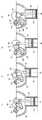
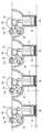
도 3은 본 발명의 실시예에 따른 가변 압축비 장치가 고압축비 상태에서 작 동하는 경우의 작동도이고, 도 4는 본 발명의 실시예에 따른 가변 압축비 장치가 저압축비 상태에서 작동하는 경우의 작동도이다.3 is an operation diagram when the variable compression ratio device according to an embodiment of the present invention operates in a high compression ratio state, and FIG. 4 is an operation example when the variable compression ratio device according to an embodiment of the present invention operates in a low compression ratio state. It is also.
도 3 및 도 4에 도시된 바와 같이, 편심 캠축(110)이 회전함에 따라 주 제어 링크(90)와 부 제어 링크(100) 사이의 각도(θ )가 변화하게 되고 이에 따라 혼합기의 압축비와 행정(stroke)이 변화한다.As shown in FIGS. 3 and 4, as the
혼합기의 압축비와 행정의 변화를, 도 5 및 도 6을 참조로, 더욱 상세히 설명한다.Changes in compression ratio and stroke of the mixer will be described in more detail with reference to FIGS. 5 and 6.
도 5는 본 발명의 실시예에 따른 가변 압축비 장치에서 편심 캠축의 회전에 대응하여 피스톤의 상사점의 위치 변화를 보인 설명도이고, 도 6은 본 발명의 실시예에 따른 가변 압축비 장치에서 편심 캠축의 회전에 대응하여 피스톤의 하사점의 위치 변화를 보인 설명도이다.5 is an explanatory view showing the position change of the top dead center of the piston in response to the rotation of the eccentric cam shaft in the variable compression ratio device according to an embodiment of the present invention, Figure 6 is an eccentric cam in a variable compression ratio device according to an embodiment of the present invention It is explanatory drawing which showed the position change of the bottom dead center of a piston corresponding to rotation of an axis.
도 5에서 "Y"는 혼합기의 최대 압축비에서 피스톤(40)의 상사점(Top Dead Center; TDP)을 나타내는 것으로, 기준 위치라고 하자.In FIG. 5, "Y" represents the top dead center (TDP) of the
도 5에 도시된 바와 같이, 편심 캠축(110)이 회전함에 따라 피스톤(40)의 상사점은 기준 위치(Y)로부터 낮아지게 된다. 즉, 기준 위치와 현재의 상사점 사이의 거리를 "d"로 표현하면, 편심 캠축(110)이 회전함에 따라 "d"는 증가하게 되고 이에 따라 혼합기의 압축비는 낮아지게 된다.As shown in FIG. 5, the top dead center of the
도 6에서 "X1"은 최대 압축비에서 피스톤(40)의 하사점(Bottom Dead Center; BDP)을 나타내는 것이고 "X2"는 최소 압축비에서 피스톤(40)의 하사점을 나타낸 것이다.In Figure 6 "X1" represents the bottom dead center (BDP) of the
앞에서 언급한 바와 같이, 최소 압축비에서의 피스톤(40)의 상사점은 최대 압축비에서의 피스톤(40)의 상사점보다 "d"만큼 낮고, 최소 압축비에서의 피스톤(40)의 하사점(X2)은 최대 압축비에서의 피스톤(40)의 하사점(X1)은 보다 낮다. 이 경우, "X1"과 "X2"의 높이 차가 "d"보다 크기 때문에 최소 압축비에서 행정은 최대 압축비에서의 행정보다 길게 된다. 행정은 배기량과 관계가 있으므로 최소 압축비의 배기량은 최대 압축비에서의 배기량보다 많게 된다.As mentioned earlier, the top dead center of the
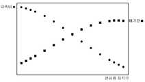
도 7은 본 발명의 실시예에 따른 가변 압축비 장치에서 배기량과 압축비의 함수를 보인 그래프이다.7 is a graph showing a function of displacement and compression ratio in a variable compression ratio apparatus according to an embodiment of the present invention.
도 7에 도시된 바와 같이, 본 발명의 실시예에 따른 가변 압축비 장치에 의하면, 배기량과 압축비는 역함수 관계에 있음을 알 수 있다. 따라서, 본 발명의 실시예에 따른 가변 압축비 장치는 편심 캠축(110)을 회전시킴으로써 배기량과 압축비를 모두 제어할 수 있다.As shown in FIG. 7, according to the variable compression ratio apparatus according to the embodiment of the present invention, it can be seen that the displacement and the compression ratio are in inverse functions. Therefore, the variable compression ratio apparatus according to the embodiment of the present invention can control both the displacement and the compression ratio by rotating the
이상으로 본 발명에 관한 바람직한 실시예를 설명하였으나, 본 발명은 상기 실시예에 한정되지 아니하며, 본 발명의 실시예로부터 당해 발명이 속하는 기술분야에서 통상의 지식을 가진 자에 의한 용이하게 변경되어 균등하다고 인정되는 범위의 모든 변경을 포함한다.Although the preferred embodiments of the present invention have been described above, the present invention is not limited to the above embodiments, and easily changed and equalized by those skilled in the art from the embodiments of the present invention. It includes all changes to the extent deemed acceptable.
도 1은 본 발명의 실시예에 따른 가변 압축비 장치의 구성도이다.1 is a block diagram of a variable compression ratio device according to an embodiment of the present invention.
도 2는 본 발명의 실시예에 따른 편심 캠축의 사시도이다.2 is a perspective view of an eccentric camshaft according to an embodiment of the present invention.
도 3은 본 발명의 실시예에 따른 가변 압축비 장치가 고압축비 상태에서 작동하는 경우의 작동도이다.3 is an operation diagram when the variable compression ratio apparatus according to the embodiment of the present invention operates in a high compression ratio state.
도 4는 본 발명의 실시예에 따른 가변 압축비 장치가 저압축비 상태에서 작동하는 경우의 작동도이다.4 is an operation diagram when the variable compression ratio device according to the embodiment of the present invention operates in a low compression ratio state.
도 5는 본 발명의 실시예에 따른 가변 압축비 장치에서 편심 캠축의 회전에 대응하여 피스톤의 상사점의 위치 변화를 보인 설명도이다.5 is an explanatory view showing a position change of the top dead center of the piston in response to the rotation of the eccentric camshaft in the variable compression ratio apparatus according to the embodiment of the present invention.
도 6은 본 발명의 실시예에 따른 가변 압축비 장치에서 편심 캠축의 회전에 대응하여 피스톤의 하사점의 위치 변화를 보인 설명도이다.6 is an explanatory view showing the position change of the bottom dead center of the piston in response to the rotation of the eccentric camshaft in the variable compression ratio apparatus according to the embodiment of the present invention.
도 7은 본 발명의 실시예에 따른 가변 압축비 장치에서 배기량과 압축비의 함수를 보인 그래프이다.7 is a graph showing a function of displacement and compression ratio in a variable compression ratio apparatus according to an embodiment of the present invention.
Claims (9)
Translated fromKoreanPriority Applications (3)
| Application Number | Priority Date | Filing Date | Title |
|---|---|---|---|
| KR1020080065654AKR100969385B1 (en) | 2008-07-07 | 2008-07-07 | Variable compression ratio apparatus |
| US12/498,271US8074613B2 (en) | 2008-07-07 | 2009-07-06 | Variable compression ratio apparatus |
| CN200910151392.0ACN101624939B (en) | 2008-07-07 | 2009-07-06 | Variable compression ratio apparatus |
Applications Claiming Priority (1)
| Application Number | Priority Date | Filing Date | Title |
|---|---|---|---|
| KR1020080065654AKR100969385B1 (en) | 2008-07-07 | 2008-07-07 | Variable compression ratio apparatus |
Publications (2)
| Publication Number | Publication Date |
|---|---|
| KR20100005565A KR20100005565A (en) | 2010-01-15 |
| KR100969385B1true KR100969385B1 (en) | 2010-07-09 |
Family
ID=41463377
Family Applications (1)
| Application Number | Title | Priority Date | Filing Date |
|---|---|---|---|
| KR1020080065654AExpired - Fee RelatedKR100969385B1 (en) | 2008-07-07 | 2008-07-07 | Variable compression ratio apparatus |
Country Status (3)
| Country | Link |
|---|---|
| US (1) | US8074613B2 (en) |
| KR (1) | KR100969385B1 (en) |
| CN (1) | CN101624939B (en) |
Families Citing this family (20)
| Publication number | Priority date | Publication date | Assignee | Title |
|---|---|---|---|---|
| US8352400B2 (en) | 1991-12-23 | 2013-01-08 | Hoffberg Steven M | Adaptive pattern recognition based controller apparatus and method and human-factored interface therefore |
| US7904187B2 (en) | 1999-02-01 | 2011-03-08 | Hoffberg Steven M | Internet appliance system and method |
| DE102010032486A1 (en)* | 2010-07-28 | 2012-02-02 | Daimler Ag | Method for operating a reciprocating piston engine |
| KR101163700B1 (en)* | 2010-08-23 | 2012-07-09 | 현대자동차주식회사 | Variable compression ratio apparatus |
| US10504130B2 (en)* | 2011-07-24 | 2019-12-10 | Overstock.Com, Inc. | Methods and systems for incentivizing online retail purchasers to elicit additional online sales |
| US8671895B2 (en) | 2012-05-22 | 2014-03-18 | Michael Inden | Variable compression ratio apparatus with reciprocating piston mechanism with extended piston offset |
| KR101361514B1 (en)* | 2012-07-11 | 2014-02-12 | 현대자동차주식회사 | Variable compression ratio apparatus |
| KR101316881B1 (en)* | 2012-07-23 | 2013-10-08 | 현대자동차주식회사 | Variable compression ratio apparatus |
| DE112013003765A5 (en)* | 2012-07-30 | 2015-08-20 | Fev Gmbh | Actuation unit for variable engine components |
| EP2992200B1 (en)* | 2013-05-03 | 2019-07-03 | Blackstock, Scott | Variable compression ratio engine |
| CN104047830B (en)* | 2014-06-13 | 2016-06-22 | 江苏盈科汽车空调有限公司 | A kind of compressor of variable compressive amount |
| CN104500242B (en)* | 2015-01-09 | 2023-08-22 | 范伟俊 | Variable compression ratio engine |
| KR101806157B1 (en)* | 2015-12-15 | 2017-12-07 | 현대자동차 주식회사 | Variable compression ratio apparatus |
| US10289544B2 (en)* | 2016-07-19 | 2019-05-14 | Western Digital Technologies, Inc. | Mapping tables for storage devices |
| KR102406127B1 (en)* | 2017-10-16 | 2022-06-07 | 현대자동차 주식회사 | Variable compression ratio engine |
| GB2575850B (en)* | 2018-07-26 | 2020-08-05 | Abdulkadir Omer Bndean | Transport system using renewable energy |
| CN110486158B (en)* | 2018-10-30 | 2024-10-29 | 长城汽车股份有限公司 | Stroke-variable compression ratio mechanism and control method thereof |
| CN110671199B (en)* | 2018-12-30 | 2021-07-06 | 长城汽车股份有限公司 | Variable compression ratio mechanism and engine |
| CN110657024A (en)* | 2018-12-30 | 2020-01-07 | 长城汽车股份有限公司 | Variable compression ratio mechanism and engine |
| US11092090B1 (en)* | 2020-09-30 | 2021-08-17 | GM Global Technology Operations LLC | Multilink cranktrains with combined eccentric shaft and camshaft drive system for internal combustion engines |
Citations (2)
| Publication number | Priority date | Publication date | Assignee | Title |
|---|---|---|---|---|
| KR20050016093A (en)* | 2003-08-05 | 2005-02-21 | 혼다 기켄 고교 가부시키가이샤 | Variable compression ratio engine |
| KR100576964B1 (en) | 2002-04-17 | 2006-05-10 | 혼다 기켄 고교 가부시키가이샤 | Stroke variable engine |
Family Cites Families (10)
| Publication number | Priority date | Publication date | Assignee | Title |
|---|---|---|---|---|
| GB245188A (en)* | 1924-09-25 | 1925-12-28 | Walter Frederick Thomas | Improvements in or relating to reciprocating engines |
| GB353986A (en)* | 1930-05-27 | 1931-08-06 | Henri Kundig | Improvements in a variable and regulatable compression chamber for internal combustion or other engines |
| US4517931A (en)* | 1983-06-30 | 1985-05-21 | Nelson Carl D | Variable stroke engine |
| US5243938A (en)* | 1992-07-30 | 1993-09-14 | Yan Miin J | Differential stroke internal combustion engine |
| JP2001227367A (en)* | 2000-02-16 | 2001-08-24 | Nissan Motor Co Ltd | Reciprocating internal combustion engine |
| JP3941371B2 (en)* | 2000-10-12 | 2007-07-04 | 日産自動車株式会社 | Variable compression ratio mechanism of internal combustion engine |
| EP1347161B1 (en)* | 2002-03-20 | 2007-06-27 | Honda Giken Kogyo Kabushiki Kaisha | Variable compression ratio engine |
| US6672270B2 (en)* | 2002-05-31 | 2004-01-06 | Rollin A. Armer | Fuel efficient valve mechanism for internal combustion engines |
| JP2006083729A (en)* | 2004-09-14 | 2006-03-30 | Honda Motor Co Ltd | Vehicle control device |
| KR100921806B1 (en)* | 2007-11-29 | 2009-10-16 | 현대자동차주식회사 | Variable compression ratio |
- 2008
- 2008-07-07KRKR1020080065654Apatent/KR100969385B1/ennot_activeExpired - Fee Related
- 2009
- 2009-07-06USUS12/498,271patent/US8074613B2/ennot_activeExpired - Fee Related
- 2009-07-06CNCN200910151392.0Apatent/CN101624939B/ennot_activeExpired - Fee Related
Patent Citations (2)
| Publication number | Priority date | Publication date | Assignee | Title |
|---|---|---|---|---|
| KR100576964B1 (en) | 2002-04-17 | 2006-05-10 | 혼다 기켄 고교 가부시키가이샤 | Stroke variable engine |
| KR20050016093A (en)* | 2003-08-05 | 2005-02-21 | 혼다 기켄 고교 가부시키가이샤 | Variable compression ratio engine |
Also Published As
| Publication number | Publication date |
|---|---|
| US8074613B2 (en) | 2011-12-13 |
| CN101624939A (en) | 2010-01-13 |
| CN101624939B (en) | 2014-07-16 |
| KR20100005565A (en) | 2010-01-15 |
| US20100000497A1 (en) | 2010-01-07 |
Similar Documents
| Publication | Publication Date | Title |
|---|---|---|
| KR100969385B1 (en) | Variable compression ratio apparatus | |
| KR101020826B1 (en) | Variable compression ratio | |
| KR101806157B1 (en) | Variable compression ratio apparatus | |
| KR100969376B1 (en) | Variable compression ratio | |
| KR101090801B1 (en) | Variable compression ratio apparatus | |
| KR101198786B1 (en) | Variable compression ratio apparatus | |
| CN104321517B (en) | The control gear of internal-combustion engine and controlling method | |
| KR101180953B1 (en) | Variable compression ratio apparatus | |
| KR20090055931A (en) | Variable compression ratio | |
| JP6564652B2 (en) | COMPRESSION RATIO ADJUSTING DEVICE FOR INTERNAL COMBUSTION ENGINE AND METHOD FOR CONTROLLING COMPRESSION RATIO ADJUSTING DEVICE FOR INTERNAL COMBUSTION ENGINE | |
| WO2019035312A1 (en) | Variable operation system for internal combustion engine, and control device therefor | |
| KR20140010512A (en) | Variable compression ratio apparatus | |
| US7228838B2 (en) | Internal combustion engine | |
| KR101361514B1 (en) | Variable compression ratio apparatus | |
| JP6285301B2 (en) | Control device for internal combustion engine | |
| US8229649B2 (en) | Spark ignition type internal combustion engine | |
| JP2007071046A (en) | Internal combustion engine with variable compression ratio mechanism | |
| JP4501584B2 (en) | COMPRESSION RATIO CONTROL DEVICE FOR INTERNAL COMBUSTION ENGINE | |
| JP2008101520A (en) | Miller cycle engine | |
| KR100999623B1 (en) | Variable compression ratio device and engine using same | |
| KR20110001510A (en) | Variable compression ratio | |
| KR20110001520A (en) | Variable compression ratio | |
| JP2005220754A (en) | Internal combustion engine with variable compression ratio mechanism | |
| JP2014227936A (en) | Internal combustion engine | |
| KR20090094598A (en) | Variable compression ratio apparatus |
Legal Events
| Date | Code | Title | Description |
|---|---|---|---|
| A201 | Request for examination | ||
| PA0109 | Patent application | St.27 status event code:A-0-1-A10-A12-nap-PA0109 | |
| PA0201 | Request for examination | St.27 status event code:A-1-2-D10-D11-exm-PA0201 | |
| PG1501 | Laying open of application | St.27 status event code:A-1-1-Q10-Q12-nap-PG1501 | |
| D13-X000 | Search requested | St.27 status event code:A-1-2-D10-D13-srh-X000 | |
| D14-X000 | Search report completed | St.27 status event code:A-1-2-D10-D14-srh-X000 | |
| E701 | Decision to grant or registration of patent right | ||
| PE0701 | Decision of registration | St.27 status event code:A-1-2-D10-D22-exm-PE0701 | |
| GRNT | Written decision to grant | ||
| PR0701 | Registration of establishment | St.27 status event code:A-2-4-F10-F11-exm-PR0701 | |
| PR1002 | Payment of registration fee | St.27 status event code:A-2-2-U10-U11-oth-PR1002 Fee payment year number:1 | |
| PG1601 | Publication of registration | St.27 status event code:A-4-4-Q10-Q13-nap-PG1601 | |
| PN2301 | Change of applicant | St.27 status event code:A-5-5-R10-R13-asn-PN2301 St.27 status event code:A-5-5-R10-R11-asn-PN2301 | |
| FPAY | Annual fee payment | Payment date:20130627 Year of fee payment:4 | |
| PR1001 | Payment of annual fee | St.27 status event code:A-4-4-U10-U11-oth-PR1001 Fee payment year number:4 | |
| LAPS | Lapse due to unpaid annual fee | ||
| PC1903 | Unpaid annual fee | St.27 status event code:A-4-4-U10-U13-oth-PC1903 Not in force date:20140703 Payment event data comment text:Termination Category : DEFAULT_OF_REGISTRATION_FEE | |
| PC1903 | Unpaid annual fee | St.27 status event code:N-4-6-H10-H13-oth-PC1903 Ip right cessation event data comment text:Termination Category : DEFAULT_OF_REGISTRATION_FEE Not in force date:20140703 | |
| R18-X000 | Changes to party contact information recorded | St.27 status event code:A-5-5-R10-R18-oth-X000 | |
| R18-X000 | Changes to party contact information recorded | St.27 status event code:A-5-5-R10-R18-oth-X000 |