KR100968205B1 - Infrared camera space touch sensing device, method and screen device - Google Patents
Infrared camera space touch sensing device, method and screen deviceDownload PDFInfo
- Publication number
- KR100968205B1 KR100968205B1KR1020080042547AKR20080042547AKR100968205B1KR 100968205 B1KR100968205 B1KR 100968205B1KR 1020080042547 AKR1020080042547 AKR 1020080042547AKR 20080042547 AKR20080042547 AKR 20080042547AKR 100968205 B1KR100968205 B1KR 100968205B1
- Authority
- KR
- South Korea
- Prior art keywords
- infrared
- space
- depth information
- infrared camera
- depth
- Prior art date
- Legal status (The legal status is an assumption and is not a legal conclusion. Google has not performed a legal analysis and makes no representation as to the accuracy of the status listed.)
- Expired - Fee Related
Links
Images


Classifications
- G—PHYSICS
- G06—COMPUTING OR CALCULATING; COUNTING
- G06F—ELECTRIC DIGITAL DATA PROCESSING
- G06F3/00—Input arrangements for transferring data to be processed into a form capable of being handled by the computer; Output arrangements for transferring data from processing unit to output unit, e.g. interface arrangements
- G06F3/01—Input arrangements or combined input and output arrangements for interaction between user and computer
- G06F3/03—Arrangements for converting the position or the displacement of a member into a coded form
- G06F3/041—Digitisers, e.g. for touch screens or touch pads, characterised by the transducing means
- G06F3/042—Digitisers, e.g. for touch screens or touch pads, characterised by the transducing means by opto-electronic means
- G06F3/0425—Digitisers, e.g. for touch screens or touch pads, characterised by the transducing means by opto-electronic means using a single imaging device like a video camera for tracking the absolute position of a single or a plurality of objects with respect to an imaged reference surface, e.g. video camera imaging a display or a projection screen, a table or a wall surface, on which a computer generated image is displayed or projected
- G—PHYSICS
- G06—COMPUTING OR CALCULATING; COUNTING
- G06F—ELECTRIC DIGITAL DATA PROCESSING
- G06F3/00—Input arrangements for transferring data to be processed into a form capable of being handled by the computer; Output arrangements for transferring data from processing unit to output unit, e.g. interface arrangements
- G06F3/01—Input arrangements or combined input and output arrangements for interaction between user and computer
- G06F3/017—Gesture based interaction, e.g. based on a set of recognized hand gestures
- G—PHYSICS
- G06—COMPUTING OR CALCULATING; COUNTING
- G06F—ELECTRIC DIGITAL DATA PROCESSING
- G06F3/00—Input arrangements for transferring data to be processed into a form capable of being handled by the computer; Output arrangements for transferring data from processing unit to output unit, e.g. interface arrangements
- G06F3/01—Input arrangements or combined input and output arrangements for interaction between user and computer
- G06F3/03—Arrangements for converting the position or the displacement of a member into a coded form
- G06F3/041—Digitisers, e.g. for touch screens or touch pads, characterised by the transducing means
- G06F3/0416—Control or interface arrangements specially adapted for digitisers
Landscapes
- Engineering & Computer Science (AREA)
- General Engineering & Computer Science (AREA)
- Theoretical Computer Science (AREA)
- Human Computer Interaction (AREA)
- Physics & Mathematics (AREA)
- General Physics & Mathematics (AREA)
- Multimedia (AREA)
- Position Input By Displaying (AREA)
- Studio Devices (AREA)
Abstract
Translated fromKorean
Description
Translated fromKorean본 발명은 적외선 카메라 방식의 공간 터치 감지 장치, 방법 및 스크린 장치에 관한 것으로서, 구체적으로는 공간상에 투영된 메뉴의 선택을 감지하기 위해 적외선 카메라를 사용하는 적외선 카메라 방식의 공간 터치 감지 장치, 방법 및 스크린 장치에 관한 것이다.The present invention relates to an infrared camera type spatial touch sensing apparatus, a method and a screen device, and more particularly, to an infrared camera type spatial touch sensing apparatus and method using an infrared camera to detect a selection of a menu projected on a space. And a screen device.
최근, 키보드를 사용하지 않고 화면(스크린)에 나타난 문자나 특정 위치에 사람의 손 또는 물체가 닿으면, 그 위치를 파악하여 저장된 소프트웨어에 의해 파악한 위치에 대응하는 기능을 처리하도록 하는 터치스크린이 널리 사용되고 있다.Recently, when a person's hand or an object touches a character or a specific location displayed on the screen (screen) without using a keyboard, a touch screen that detects the location and processes a function corresponding to the location detected by the stored software is widely used. It is used.
터치 스크린은 기능에 해당하는 문자나 그림 정보를 다양하게 표시할 수 있어 사용자의 기능 인지를 용이하게 한다. 때문에, 지하철, 백화점, 은행 등의 장소에서 안내용 기기, 점포의 판매용 단말기 및 일반 업무용 기기 등에 적용되어 다양하게 활용되고 있다.The touch screen may display a variety of text or picture information corresponding to a function, thereby facilitating user's recognition of the function. Therefore, it is widely used in applications such as guide devices, store sales terminals and general business devices in places such as subways, department stores, banks, and the like.
종래의 터치스크린은 모니터의 화면에 터치 패널(Touch Panel)을 덧붙여서 손끝이나 기타 물체가 소정영역에 접촉할 때 해당 영역의 특성이 변화하는 것을 인지하여 사용자 입력의 발생을 감지하였다.The conventional touch screen detects the occurrence of user input by adding a touch panel to the screen of the monitor and recognizing that the characteristics of the corresponding area change when a fingertip or other object contacts a predetermined area.
즉, 종래의 터치스크린은 전체 화면을 2차원 격자 형태로 구분하여 접촉된 위치를 해석하였다.That is, the conventional touch screen analyzes the contact position by dividing the entire screen into a two-dimensional grid.
이때, 터치스크린은 접촉 감지를 위해 물체의 접촉에 의해 정전용량, 초음파, 적외선, 저항막, 음파인식 등을 적용한 터치 패널의 특성이 변화하는 원리를 이용하였다.In this case, the touch screen uses a principle that changes the characteristics of the touch panel to which the capacitance, ultrasonic waves, infrared rays, resistive film, sound wave recognition, etc. are applied by the contact of the object to detect the touch.
즉, 종래의 터치스크린은 디스플레이 화면과 터치 패널을 동일한 면에 배치하는 2차원 형태로 구성되었으므로, 공간상에 투영된 메뉴 아이콘에 대한 사용자 인터페이스를 제공하지는 못하였다.That is, the conventional touch screen is configured in a two-dimensional form in which the display screen and the touch panel are disposed on the same surface, and thus cannot provide a user interface for the menu icon projected on the space.
본 발명의 목적은 공간상에 메뉴를 투영하여 3차원적인 사용자 인터페이스를 제공하는 적외선 카메라 방식의 공간 터치 감지 장치, 방법 및 스크린 장치를 제공함에 있다.Disclosure of Invention An object of the present invention is to provide an infrared camera type spatial touch sensing apparatus, a method and a screen apparatus that project a menu onto a space to provide a three-dimensional user interface.
본 발명의 다른 목적은 물체의 적외선 촬영 영상을 사용하여 감지공간 내 메뉴 선택을 입력받는 적외선 카메라 방식의 공간 터치 감지 장치, 방법 및 스크린 장치를 제공함에 있다.Another object of the present invention is to provide an infrared camera type spatial touch sensing apparatus, method, and screen apparatus that receive a menu selection in a sensing space using an infrared photographed image of an object.
전술한 문제점을 해결하고자, 본 발명의 일면에 따른 적외선 카메라 방식의 공간 터치 감지 장치는 공간상에 적어도 하나의 기능 실행 메뉴를 투영하며 다수의 픽셀을 포함하는 스크린상의, 감지공간을 적외선 촬영하는 두 개 또는 그 이상의 적외선 카메라; 상기 두 개 또는 그 이상의 적외선 카메라에 의한 촬영 영상의 적외선 값을 이용하여 상기 감지공간 내에 진입한 상기 사용자 지시수단의 깊이 정보를 상기 픽셀 단위로 추출하는 깊이정보 추출기; 상기 추출된 깊이 정보에 대응하는 진입 깊이가 임계 깊이 이상이면, 상기 픽셀 단위로 추출된 깊이 정보로부터 상기 사용자 지시수단의 위치 좌표를 추출하는 공간좌표 연산기; 및 상기 감지공간 내에 적외선을 투사하여 상기 촬영의 감도를 개선하는 적어도 하나의 적외선 투광기를 포함하며, 상기 적외선 카메라는, 외부조명으로 인한 상기 사용자 지시수단의 오인식을 줄이도록 880nm이하 가시광선을 차단하는 필터를 구비한 것을 특징으로 한다.In order to solve the above-described problem, an infrared camera-type spatial touch sensing apparatus according to an aspect of the present invention projects two infrared rays of a sensing space on a screen including a plurality of pixels while projecting at least one function execution menu onto the space. Or more infrared cameras; A depth information extractor for extracting depth information of the user indicating means entered into the sensing space in units of pixels by using infrared values of the captured images of the two or more infrared cameras; A spatial coordinate calculator for extracting the position coordinates of the user indicating means from the depth information extracted in units of pixels when the entry depth corresponding to the extracted depth information is greater than or equal to a threshold depth; And at least one infrared light emitter for projecting infrared rays in the sensing space to improve the sensitivity of the photographing, wherein the infrared camera blocks visible light of 880 nm or less so as to reduce misunderstanding of the user indicating means due to external lighting. It is characterized by including a filter.
본 발명의 다른 면에 따른 적외선 카메라 방식의 공간 터치 감지 방법은, 적어도 하나의 기능 실행 메뉴를 포함하며, 다수의 픽셀을 포함하는 스크린을 공간상에 투영하는 단계; 상기 스크린상의 감지공간을 두 개 또는 그 이상의 적외선 카메라로 각각 적외선 촬영하는 단계; 상기 각각 적외선 촬영된 촬영 영상의 적외선 값을 이용하여 상기 감지공간 내에 진입한 상기 사용자 지시수단의 깊이 정보를 상기 픽셀 단위로 추출하는 단계; 상기 추출한 깊이 정보에 대응하는 진입 깊이가 임계 깊이 이상이면, 상기 픽셀 단위로 추출된 깊이 정보로부터 상기 사용자 지시수단의 위치 좌표를 추출하는 단계를 포함하되, 상기 촬영하는 단계는, 상기 촬영의 감도가 개선되도록, 상기 감지공간 내에 적외선을 투사하는 단계와, 외부조명으로 인한 상기 사용자 지시수단의 오인식을 줄이도록, 880nm이하 가시광선을 차단하는 단계를 선택적으로 포함하는 것을 특징으로 한다.According to another aspect of the present invention, there is provided a method of detecting a spatial touch using an infrared camera, including: projecting a screen including at least one function execution menu and including a plurality of pixels in a space; Infrared imaging each of the sensing spaces on the screen with two or more infrared cameras; Extracting depth information of the user indicating means entered into the sensing space by the pixel unit by using infrared values of the captured images captured by the infrared rays; If the entry depth corresponding to the extracted depth information is greater than or equal to a threshold depth, extracting the position coordinates of the user indicating means from the depth information extracted in units of pixels, wherein the photographing step, the sensitivity of the shooting Projecting infrared rays in the sensing space, and blocking visible light of 880 nm or less so as to improve misrecognition of the user indicating means due to external illumination.
본 발명의 또 다른 면에 따른 적외선 카메라 방식의 스크린 장치는, 적어도 하나의 기능 실행 메뉴를 포함하는 인터페이스 화면을 공간상에 투영하며, 다수의 픽셀을 포함하는 스크린; 상기 스크린상의 감지공간을 각각 적외선 촬영하는 두 개 또는 그 이상의 적외선 카메라; 상기 각각 적외선 촬영된 촬영 영상의 적외선 값을 이용하여 상기 감지공간 내에 진입한 사용자 지시수단의 깊이 정보를 상기 픽셀 단위로 추출하는 깊이정보 추출기; 상기 추출한 깊이 정보에 대응하는 진입 깊이가 임계 깊이 이상이면, 상기 픽셀 단위로 추출된 깊이 정보로부터 상기 사용자 지시수단의 위치 좌표를 추출하는 공간좌표 연산기; 상기 적어도 하나의 기능 실행 메뉴 중 상기 추출된 위치 좌표에 해당하는 기능 실행 메뉴를 인지하고, 상기 인지된 기능 실행 메뉴에 대응하는 기능 실행 이벤트를 발생시키는 이벤트 발생기; 상기 감지공간 내에 적외선을 투사하여 상기 촬영의 감도를 개선하는 적어도 하나의 적외선 투광기; 및 외부조명으로 인한 상기 사용자 지시수단의 오인식을 줄이도록 880nm이하 가시광선을 차단하는 필터를 포함하는 것을 를 특징으로 한다.In accordance with another aspect of the present invention, an infrared camera type screen device includes: a screen projecting an interface screen including at least one function execution menu onto a space and including a plurality of pixels; Two or more infrared cameras which respectively photograph the sensing space on the screen; A depth information extractor for extracting depth information of a user indicating means entered into the sensing space by the pixel unit by using infrared values of the captured images of the infrared rays; A spatial coordinate calculator for extracting the position coordinates of the user indicating means from the depth information extracted in units of pixels when the entry depth corresponding to the extracted depth information is greater than or equal to a threshold depth; An event generator for recognizing a function execution menu corresponding to the extracted position coordinates among the at least one function execution menu and generating a function execution event corresponding to the recognized function execution menu; At least one infrared light emitter for projecting infrared rays into the sensing space to improve sensitivity of the photographing; And a filter for blocking visible light of 880 nm or less so as to reduce misunderstanding of the user indicating means due to external illumination.
본 발명에 따르면, 적외선 카메라를 통한 적외선 촬영 영상으로 감지공간 내로 진입하는 사용자 지시수단을 감지할 수 있으며, 적외선 카메라에 가시광선 차단 필터 등의 적용하여 외부 조명에 의한 오인식을 방지할 수 있는 효과가 있다.According to the present invention, it is possible to detect a user indicating means entering the sensing space as an infrared photographed image through an infrared camera, and by applying a visible light blocking filter to the infrared camera, there is an effect of preventing misrecognition by external lighting. have.
이하, 본 발명에 따른 바람직한 실시예를 첨부 도면을 참조하여 상세히 설명한다.Hereinafter, exemplary embodiments of the present invention will be described in detail with reference to the accompanying drawings.
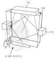
도 1은 본 발명의 일실시예에 따른 적외선 카메라 방식의 공간 터치 감지 장치를 도시한 구성도이며, 도 2 및 도 3은 본 발명의 일실시예에 따른 적외선 카메 라(110) 및 적외선 투광기(170)의 설치도이다.1 is a block diagram showing a spatial touch sensing device of the infrared camera method according to an embodiment of the present invention, Figures 2 and 3 are an
도 1에 도시된 바와 같이, 본 발명에 따른 적외선 카메라 방식의 공간 터치 감지 장치는 적어도 하나의 적외선 카메라(110), 깊이정보 추출기(120), 공간좌표 연산기(130)를 포함한다.As shown in FIG. 1, an infrared camera type spatial touch sensing apparatus according to the present invention includes at least one
적외선 카메라(110)는 감지공간(100)의 측면에 하나 이상 설치되어 스크린 상의 감지공간(100)을 적외선 촬영한다.At least one
여기서, 감지 공간은 스크린 상의 3차원 공간으로서, 적외선 카메라(110)가 사용자 지시수단의 진입 여부를 감지할 수 있는 영역일 수 있다. 이러한 감지 공간은 스크린의 크기 및/또는 적외선 카메라(110)의 감지 가능 범위 등에 의해 결정될 수 있다.Here, the sensing space is a three-dimensional space on the screen, and may be an area where the
이때, 감지공간(100)은 스크린과 대응하는 형태로 구성되어 일 측을 개방하고 타 측을 스크린과 중첩하여 설치하고, 직사각형인 스크린의 형태에 대응하는 직육면체 형태로 구성되는 것이 바람직하다.At this time, the
적외선 카메라(110)는 도 2에 도시된 바와 같이, 감지공간(100)의 좌우에 설치되어 감지공간(100) 내에서 촬영 영역을 교차시켜 촬영하여 깊이정보 추출기(120)가 두 개의 적외선 카메라(110)로 교차 촬영한 영상의 시차를 이용하여 사용자 지시수단의 감지공간(100)으로 진입한 깊이 정보를 추출할 수 있도록 한다.As shown in FIG. 2, the
여기서, 적외선 카메라(110)는 적외선 건판을 사용하여 촬영하는 카메라로서, 원경 촬영, 특수 감열체에 의한 열 사진 촬영, 방사도의 측정 및 미소(微小) 온도 차의 검출에 이용될 수 있다.Here, the
적외선 카메라(110)는 880nm이하의 가시광선을 차단하는 필터를 구비하여 외부 조명의 영향을 차단하므로 사용자 지시수단에 대한 감지 신뢰도가 높다.The
적외선 카메라(110)는 감지공간(100)의 상하 또는 좌우 측면에 설치되어 감지공간(100) 내에서 촬영 영역을 교차시켜 촬영하여 시차에 의해 사용자 지시수단이 감지공간(100) 내로 진입한 정도(깊이)를 파악할 수 있다.The
이때, 깊이 정보 추출을 위해 적외선 카메라(110)로 한 대의 광각 단초점 적외선 카메라를 사용할 수도 있으나, 광각 단초점 적외선 카메라는 왜곡이 크며, 처리연산이 복잡하고, 가격이 높은 등의 단점이 있어 두 대의 범용 적외선 카메라로 촬영한 영상의 시차를 이용하여 깊이 정보를 추출하는 것이 바람직하다.In this case, a single wide-angle single-focal infrared camera may be used as the
깊이정보 추출기(120)는 적외선 촬영된 영상으로부터 감지공간(100) 내에 진입한 사용자 지시수단의 깊이 정보를 추출한다.The
상세하게는, 깊이정보 추출기(120)는 복수의 적외선 카메라(110)에 의해 교차되어 촬영된 영상을 원근보정하여 스크린의 정면에서 촬영하였을 때와 동일한 시야각을 갖도록 각각 변환하고, 각 원근보정된 영상들을 1:1로 중첩(종합)한다. 그리고, 깊이정보 추출기(120)는 종합된 영상의 적외선 값을 이용하여 사용자 지시수단의 위치를 파악하고, 파악된 위치의 깊이 정보를 추출한다. 즉, 사용자 지시수단이 위치하는 지점의 적외선 값은 다른 지점에 비해 높을 것이므로, 이 지점의 깊이 정보를 추출함으로써, 사용자 지시수단의 깊이 정보를 추출할 수 있다.In detail, the
공간좌표 연산기(130)는 추출한 깊이가 임계 깊이 이상이면, 감지공간(100) 내에 진입된 사용자 지시수단의 위치에 대응하는 스크린의 위치 좌표를 추출한다. 공간좌표 연산기(130)의 세부 구성요소 및 구체적 역할에 대해서는 도 4를 참조하 여 후술한다.If the extracted depth is greater than or equal to the threshold depth, the spatial coordinate
여기서, 위치 좌표는 스크린의 한 모서리를 기준은 X축, Y축으로 해석되는 2차원 좌표일 수 있다.Here, the position coordinates may be two-dimensional coordinates which are interpreted as X-axis and Y-axis based on one corner of the screen.
그외에도, 적외선 카메라 방식의 공간 터치 감지 장치는 이벤트 발생기(150), 송신기(140) 및 적외선 투광기(170)를 더 포함한다.In addition, the infrared camera-type spatial touch sensing apparatus further includes an
이벤트 발생기(150)는 공간 터치 감지 장치에 포함되거나 별도의 장치 일 수 있으며, 추출된 위치 좌표에 해당하는 기능 실행 이벤트를 발생시킨다.The
송신기(140)는 추출된 위치 좌표 또는 발생된 기능 실행 이벤트에 해당하는 기능 실행 장치로 추출된 위치 좌표 또는 발생된 기능 실행 이벤트를 송신한다.The
적외선 투광기(170)는 적어도 하나 구비되어 감지공간(100) 내에 적외선을 투사하여 적외선 카메라의 촬영 감도를 개선한다.At least one
적외선 투광기(170)는 감지공간(100) 내에 적외선을 균일하게 투사하는 적외선 LED(Light-Emitting Diode)일 수 있다.The
즉, 적외선 투광기(170)로서 투사각이 넓고, 투사 밀도가 비교적 균일한 광각의 저출력 LED를 적용할 수도 있다.That is, as the
적외선 투광기(170)는 적외선 카메라의 촬영 영역에 대한 적외선 투사율을 높일 수 있는 위치에 설치되는 것이 바람직하다.The
이때, 적외선 카메라(110)가 도 3에 도시된 바와 같이, 감지공간(100)의 좌우에 설치된 경우는 적외선 투광기(170)를 감지공간(100)의 상하에 설치하여 적외선 투사율을 높이는 것이 바람직하다.In this case, as shown in FIG. 3, when the
이때, 적외선 투광기(170)는 설치환경에 따라 위쪽이나 아래쪽에 한 개만 설치될 수도 있음은 물론이다.At this time, of course, only one
도 4는 본 발명의 일실시예에 따른 공간좌표 연산기(130)의 세부 구성도이다.4 is a detailed configuration diagram of the spatial coordinate
도 4에 도시된 바와 같이, 본 발명에 따른 공간좌표 연산기(130)는 깊이정보 취득부(131), 픽셀 감지부(132), 지시수단 판단부(133) 및 좌표 검출부(134)를 포함한다.As shown in FIG. 4, the spatial coordinate
깊이정보 취득부(131)는 깊이 추출기(130)로부터 전달받은 깊이 정보로부터 진입 깊이에 대응하는 제1 데이터를 픽셀단위로 취득한다.The depth
삭제delete
이때, 각 픽셀은 스크린에 대응하는 위치 정보를 가지기 때문에, 공간좌표 연산기(130)는 깊이 정보로부터 스크린의 위치 정보도 파악할 수 있다.In this case, since each pixel has location information corresponding to the screen, the spatial coordinate
삭제delete
픽셀 감지부(132)는 제1 데이터를 이용하여 감지공간(100)에 대한 물체의 진입 깊이가 임계 깊이 이상인 픽셀들을 추출한다.The
상세하게는, 픽셀 감지부(132)는 제1 데이터에 대응하는 진입 깊이와 임계 깊이 이상인지 비교하여 임계 깊이 이상인 제1 데이터를 1로 치환하고, 임계 깊이 미만인 제1 데이터를 0으로 치환한다.In detail, the
지시수단 판단부(133)는 치환된 제1 데이터가 1인 픽셀들이 이루는 픽셀 영역이 임계 영역 미만인지를 확인하고, 임계 영역 이상이면 사용자 지시수단이 진입한 것으로 판단한다.The indicating means determining
이때, 지시수단 판단부(133)는 치환된 제1 데이터가 1인 픽셀들이 이루는 픽셀 영역이 임계 영역 미만이면, 먼지 등의 불필요한 물체가 감지된 것으로 판단하고, 무시하여 오동작을 방지한다.In this case, the indicating means
좌표 검출부(134)는 사용자 지시수단의 진입으로 판단된 픽셀 영역의 중심을 검출하여 위치 좌표로 변환한다.The
예컨대, 좌표 검출부(134)는 픽셀 영역의 최장길이와 최단길이의 교차점을 중심으로 판단하여 교차점을 위치 좌표로 변환할 수 있다.For example, the
여기서, 좌표 검출부(134)는 소정(예컨대, 두 번째) 번째로 긴 길이와 소정 번째로 짧은 길이의 교차점을 중심으로 검출할 수 있으며, 그외에 다양한 방식을 사용할 수 있음은 물론이다.Here, the
도 5는 본 발명의 일실시예에 따른 적외선 카메라 방식의 스크린 장치를 도시한 구성도이다.5 is a block diagram showing a screen device of the infrared camera method according to an embodiment of the present invention.
도 5에 도시된 바와 같이, 본 발명에 따른 적외선 카메라 방식의 스크린 장치는 스크린(160), 적외선 카메라(110), 깊이정보 추출기(120), 공간좌표 연산 기(130) 및 이벤트 발생기(150)를 포함한다.As shown in FIG. 5, the screen apparatus of the infrared camera type according to the present invention includes a
스크린(160)은 스크린은 다수의 픽셀을 포함하여 적어도 하나의 기능 실행 메뉴를 표시한다.The
적외선 카메라(110)는 스크린 상의 감지공간(100) 측면에 적어도 하나 설치되어 감지공간(100) 내를 적외선 촬영한다.The
깊이정보 추출기(120)는 적외선 촬영된 영상으로부터 감지공간(100) 내에 진입한 사용자 지시수단의 깊이 정보를 추출한다.The
공간좌표 연산기(130)는 사용자 지시수단이 감지공간(100) 내 진입한 위치에 대응하는 스크린의 위치 좌표를 추출한다.The spatial coordinate
공간좌표 연산기(130)는 추출한 깊이가 임계 깊이 이상이면, 사용자 지시수단이 감지공간(100) 내 진입한 위치에 대응하는 스크린의 위치 좌표를 추출한다.If the extracted depth is greater than or equal to the threshold depth, the spatial coordinate
이벤트 발생기(150)는 적어도 하나의 기능 실행 메뉴 중 추출된 위치 좌표에 해당하는 기능 실행 메뉴를 인지하고, 인지된 기능 실행 메뉴에 대응하는 기능 실행 이벤트를 발생시킨다.The
적외선 카메라 방식의 스크린 장치는 이외에도 적어도 하나의 적외선 투광기(170)를 더 포함하고, 감지공간(100) 내에 적외선을 투사하여 적외선 카메라의 촬영 감도를 개선할 수 있다.In addition, the infrared camera type screen device may further include at least one
도 6은 본 발명의 일실시예에 따른 적외선 카메라 방식의 공간 터치 감지 방법을 도시한 흐름도이다. 이하, 도 6을 참조하여 설명한다.6 is a flowchart illustrating a spatial touch sensing method of an infrared camera method according to an embodiment of the present invention. A description with reference to FIG. 6 is as follows.
먼저, 적외선 카메라 방식의 공간 터치 감지 장치는 스크린 상의 감지공 간(100)을 적외선 촬영한다(S610).First, the infrared camera type spatial touch sensing apparatus photographs infrared rays of the
이때, 적외선 카메라 방식의 공간 터치 감지 장치는 감지공간(100)을 상기 감지공간의 상하 또는 좌우 측면에서 촬영하는 영역이 교차되도록 교차 촬영하고, 교차 촬영된 영상의 시차를 이용하여 깊이 정보를 추출한다.In this case, the infrared camera-type spatial touch sensing apparatus cross-photographs the
이때, 적외선 카메라 방식의 공간 터치 감지 장치는 촬영 영상의 화질 개선을 위해 감지공간(100) 내에 적외선을 투사하는 것이 바람직하다.In this case, it is preferable that the infrared camera type spatial touch sensing device projects infrared rays in the
이어서, 적외선 카메라 방식의 공간 터치 감지 장치는 적외선 촬영된 영상으로부터 감지공간(100)으로 진입한 사용자 지시수단의 깊이 정보를 추출한다(S620).Subsequently, the infrared camera type spatial touch sensing apparatus extracts depth information of the user indicating means entering the
상세하게는, 적외선 카메라 방식의 공간 터치 감지 장치는 교차 촬영된 영상를 원근보정하여 각각 정면 촬영 영상으로 변환하고, 각각 변환된 영상을 하나의 영상으로 종합하여 사용자 지시수단이 감지공간(100) 내 진입한 깊이 정보를 추출하는 것이다.In detail, the infrared camera-type spatial touch sensing apparatus corrects the cross-photographed image into perspective shot images, and combines the converted images into a single image, and the user indicating means enters the
그리고, 적외선 카메라 방식의 공간 터치 감지 장치는 추출한 깊이가 임계 깊이 이상이면(S630), 감지공간(100) 내에 진입된 사용자 지시수단의 위치에 대응하는 스크린의 위치 좌표를 추출한다(S640).When the extracted depth is greater than or equal to the threshold depth (S630), the infrared camera type spatial touch sensing apparatus extracts the position coordinates of the screen corresponding to the position of the user indicating means entered into the sensing space 100 (S640).
이때, 스크린은 다수의 픽셀을 포함하므로 위치 좌표도 픽셀 단위로 추출되는 것이 바람직하다.In this case, since the screen includes a plurality of pixels, the location coordinates are preferably extracted in units of pixels.
상세하게는, 적외선 카메라 방식의 공간 터치 감지 장치는 감지공간 내에 사용자 지시수단의 진입 깊이가 임계 깊이 이상인 픽셀들을 추출한다. 그리고, 추출된 픽셀들로 구성된 픽셀 영역이 임계 영역 이상이면, 사용자 지시수단이 진입한 것으로 판단하고, 사용자 지시수단의 진입으로 판단된 상기 픽셀 영역의 중심을 검출하여 위치 좌표로 변환한다.In detail, the infrared camera type spatial touch sensing apparatus extracts pixels in which the entrance depth of the user indicating means is greater than or equal to the threshold depth in the sensing space. When the pixel area composed of the extracted pixels is equal to or larger than the threshold area, it is determined that the user indicating means has entered, and the center of the pixel area determined by the user indicating means is detected and converted into position coordinates.
이때, 적외선 카메라 방식의 공간 터치 감지 장치는 픽셀 영역의 최장길이와 최단길이의 교차점을 중심으로 검출하고, 검출한 교차점을 위치 좌표로 변환하는 것이 바람직하다.In this case, it is preferable that the infrared camera type spatial touch sensing apparatus detects the intersection of the longest length and the shortest length of the pixel area and converts the detected intersection point into position coordinates.
한편, 적외선 카메라 방식의 공간 터치 감지 장치는 사용자 지시수단의 진입 깊이가 임계 깊이 미만이면(S630), 노이즈로 간주하여 무시한다(S650).On the other hand, the infrared camera-type spatial touch sensing device is regarded as noise and ignored if the entry depth of the user indicating means is less than the threshold depth (S630) (S650).
이후, 변환된 위치 좌표에 해당하는 기능 실행 이벤트가 발생 되고, 기능 실행 이벤트에 따른 기능을 실행되는 과정이 진행될 수 있다.Thereafter, a function execution event corresponding to the converted position coordinate is generated, and a process of executing a function according to the function execution event may be performed.
이상, 본 발명의 구성에 대하여 첨부 도면을 참조하여 상세히 설명하였으나, 이는 예시에 불과한 것으로서, 본 발명이 속하는 기술분야에 통상의 지식을 가진자라면 본 발명의 기술적 사상의 범위 내에서 다양한 변형과 변경이 가능함은 물론이다. 따라서 본 발명의 보호 범위는 전술한 실시예에 국한되어서는 아니되며 이하의 특허 청구범위의 기재에 의하여 정하여져야 할 것이다.While the present invention has been described in detail with reference to the accompanying drawings, it is to be understood that the invention is not limited to the above-described embodiments. Those skilled in the art will appreciate that various modifications, Of course, this is possible. Therefore, the protection scope of the present invention should not be limited to the above-described embodiment, but should be defined by the following claims.
도 1은 본 발명에 따른 적외선 카메라 방식의 공간 터치 감지 장치를 도시한 구성도.1 is a block diagram showing a spatial touch sensing device of the infrared camera method according to the present invention.
도 2 및 도 3은 본 발명에 따른 적외선 카메라(110) 및 적외선 투광기(170)의 설치도2 and 3 is an installation view of the
도 4는 본 발명에 따른 공간좌표 연산기(130)의 세부 구성도.4 is a detailed configuration diagram of the spatial coordinate
도 5는 본 발명에 따른 적외선 카메라 방식의 스크린 장치를 도시한 구성도.Figure 5 is a block diagram showing a screen device of the infrared camera method according to the present invention.
도 6은 본 발명에 따른 적외선 카메라 방식의 공간 터치 감지 방법을 도시한 흐름도.6 is a flowchart illustrating a spatial touch sensing method of an infrared camera method according to the present invention.
Claims (20)
Translated fromKoreanPriority Applications (1)
| Application Number | Priority Date | Filing Date | Title |
|---|---|---|---|
| KR1020080042547AKR100968205B1 (en) | 2008-05-07 | 2008-05-07 | Infrared camera space touch sensing device, method and screen device |
Applications Claiming Priority (1)
| Application Number | Priority Date | Filing Date | Title |
|---|---|---|---|
| KR1020080042547AKR100968205B1 (en) | 2008-05-07 | 2008-05-07 | Infrared camera space touch sensing device, method and screen device |
Publications (2)
| Publication Number | Publication Date |
|---|---|
| KR20090116544A KR20090116544A (en) | 2009-11-11 |
| KR100968205B1true KR100968205B1 (en) | 2010-07-06 |
Family
ID=41601304
Family Applications (1)
| Application Number | Title | Priority Date | Filing Date |
|---|---|---|---|
| KR1020080042547AExpired - Fee RelatedKR100968205B1 (en) | 2008-05-07 | 2008-05-07 | Infrared camera space touch sensing device, method and screen device |
Country Status (1)
| Country | Link |
|---|---|
| KR (1) | KR100968205B1 (en) |
Cited By (1)
| Publication number | Priority date | Publication date | Assignee | Title |
|---|---|---|---|---|
| WO2012015395A1 (en)* | 2010-07-27 | 2012-02-02 | Hewlett-Packard Development Company, L.P. | System and method for remote touch detection |
Families Citing this family (5)
| Publication number | Priority date | Publication date | Assignee | Title |
|---|---|---|---|---|
| KR100974894B1 (en) | 2009-12-22 | 2010-08-11 | 전자부품연구원 | 3d space touch apparatus using multi-infrared camera |
| KR101973168B1 (en) | 2012-08-24 | 2019-04-29 | 삼성디스플레이 주식회사 | touch display apparatus sensing multi touch and touch force and driving method thereof |
| KR101550601B1 (en) | 2013-09-25 | 2015-09-07 | 현대자동차 주식회사 | Curved touch display apparatus for providing tactile feedback and method thereof |
| KR101521515B1 (en)* | 2014-10-28 | 2015-05-19 | 김주희 | System and method for interworking data between multimedia devices |
| KR102174464B1 (en)* | 2018-10-08 | 2020-11-05 | 주식회사 토비스 | Space touch detecting device and display device having the same |
Citations (4)
| Publication number | Priority date | Publication date | Assignee | Title |
|---|---|---|---|---|
| JP2001282456A (en) | 2000-04-03 | 2001-10-12 | Japan Science & Technology Corp | Man-machine interface system |
| US20020041327A1 (en)* | 2000-07-24 | 2002-04-11 | Evan Hildreth | Video-based image control system |
| KR20070037773A (en)* | 2005-10-04 | 2007-04-09 | 엘지전자 주식회사 | Device and method for inputting user command in display device |
| KR100804815B1 (en) | 2007-09-10 | 2008-02-20 | (주)컴버스테크 | Touch screen using infrared camera resistant to disturbance light |
- 2008
- 2008-05-07KRKR1020080042547Apatent/KR100968205B1/ennot_activeExpired - Fee Related
Patent Citations (4)
| Publication number | Priority date | Publication date | Assignee | Title |
|---|---|---|---|---|
| JP2001282456A (en) | 2000-04-03 | 2001-10-12 | Japan Science & Technology Corp | Man-machine interface system |
| US20020041327A1 (en)* | 2000-07-24 | 2002-04-11 | Evan Hildreth | Video-based image control system |
| KR20070037773A (en)* | 2005-10-04 | 2007-04-09 | 엘지전자 주식회사 | Device and method for inputting user command in display device |
| KR100804815B1 (en) | 2007-09-10 | 2008-02-20 | (주)컴버스테크 | Touch screen using infrared camera resistant to disturbance light |
Cited By (1)
| Publication number | Priority date | Publication date | Assignee | Title |
|---|---|---|---|---|
| WO2012015395A1 (en)* | 2010-07-27 | 2012-02-02 | Hewlett-Packard Development Company, L.P. | System and method for remote touch detection |
Also Published As
| Publication number | Publication date |
|---|---|
| KR20090116544A (en) | 2009-11-11 |
Similar Documents
| Publication | Publication Date | Title |
|---|---|---|
| US9778748B2 (en) | Position-of-interest detection device, position-of-interest detection method, and position-of-interest detection program | |
| US8971565B2 (en) | Human interface electronic device | |
| US9720511B2 (en) | Hand and object tracking in three-dimensional space | |
| JP5445460B2 (en) | Impersonation detection system, impersonation detection method, and impersonation detection program | |
| US10324563B2 (en) | Identifying a target touch region of a touch-sensitive surface based on an image | |
| KR100968205B1 (en) | Infrared camera space touch sensing device, method and screen device | |
| KR20100123878A (en) | Interactive surface computer with switchable diffuser | |
| CN102939617A (en) | Gesture recognition device, gesture recognition method, and program | |
| US10664090B2 (en) | Touch region projection onto touch-sensitive surface | |
| JP5510907B2 (en) | Touch position input device and touch position input method | |
| CN103472907B (en) | Method and system for determining operation area | |
| US20020136455A1 (en) | System and method for robust foreground and background image data separation for location of objects in front of a controllable display within a camera view | |
| TW201305856A (en) | Projection system and image processing method thereof | |
| JP2012238293A (en) | Input device | |
| CN101452349B (en) | Cursor control device, method and image system on image display device | |
| JP4870651B2 (en) | Information input system and information input method | |
| Yoo et al. | Symmetrisense: Enabling near-surface interactivity on glossy surfaces using a single commodity smartphone | |
| CN108227923A (en) | A kind of virtual touch-control system and method based on body-sensing technology | |
| KR100983051B1 (en) | Depth sensor type spatial touch sensing device, method and screen device | |
| KR101019255B1 (en) | Depth sensor type spatial touch wireless terminal, its data processing method and screen device | |
| JP6027952B2 (en) | Augmented reality image generation system, three-dimensional shape data generation device, augmented reality presentation device, augmented reality image generation method, and program | |
| US9489077B2 (en) | Optical touch panel system, optical sensing module, and operation method thereof | |
| KR20090090980A (en) | Pointing device using image | |
| JP6709022B2 (en) | Touch detection device | |
| CN105653101B (en) | Touch point sensing method and optical touch system |
Legal Events
| Date | Code | Title | Description |
|---|---|---|---|
| A201 | Request for examination | ||
| PA0109 | Patent application | St.27 status event code:A-0-1-A10-A12-nap-PA0109 | |
| PA0201 | Request for examination | St.27 status event code:A-1-2-D10-D11-exm-PA0201 | |
| D13-X000 | Search requested | St.27 status event code:A-1-2-D10-D13-srh-X000 | |
| D14-X000 | Search report completed | St.27 status event code:A-1-2-D10-D14-srh-X000 | |
| E902 | Notification of reason for refusal | ||
| PE0902 | Notice of grounds for rejection | St.27 status event code:A-1-2-D10-D21-exm-PE0902 | |
| E13-X000 | Pre-grant limitation requested | St.27 status event code:A-2-3-E10-E13-lim-X000 | |
| P11-X000 | Amendment of application requested | St.27 status event code:A-2-2-P10-P11-nap-X000 | |
| P13-X000 | Application amended | St.27 status event code:A-2-2-P10-P13-nap-X000 | |
| PG1501 | Laying open of application | St.27 status event code:A-1-1-Q10-Q12-nap-PG1501 | |
| E902 | Notification of reason for refusal | ||
| PE0902 | Notice of grounds for rejection | St.27 status event code:A-1-2-D10-D21-exm-PE0902 | |
| E13-X000 | Pre-grant limitation requested | St.27 status event code:A-2-3-E10-E13-lim-X000 | |
| P11-X000 | Amendment of application requested | St.27 status event code:A-2-2-P10-P11-nap-X000 | |
| P13-X000 | Application amended | St.27 status event code:A-2-2-P10-P13-nap-X000 | |
| E701 | Decision to grant or registration of patent right | ||
| PE0701 | Decision of registration | St.27 status event code:A-1-2-D10-D22-exm-PE0701 | |
| GRNT | Written decision to grant | ||
| PR0701 | Registration of establishment | St.27 status event code:A-2-4-F10-F11-exm-PR0701 | |
| PR1002 | Payment of registration fee | St.27 status event code:A-2-2-U10-U11-oth-PR1002 Fee payment year number:1 | |
| PG1601 | Publication of registration | St.27 status event code:A-4-4-Q10-Q13-nap-PG1601 | |
| P22-X000 | Classification modified | St.27 status event code:A-4-4-P10-P22-nap-X000 | |
| FPAY | Annual fee payment | Payment date:20130111 Year of fee payment:4 | |
| PR1001 | Payment of annual fee | St.27 status event code:A-4-4-U10-U11-oth-PR1001 Fee payment year number:4 | |
| PN2301 | Change of applicant | St.27 status event code:A-5-5-R10-R13-asn-PN2301 St.27 status event code:A-5-5-R10-R11-asn-PN2301 | |
| FPAY | Annual fee payment | Payment date:20131231 Year of fee payment:5 | |
| PR1001 | Payment of annual fee | St.27 status event code:A-4-4-U10-U11-oth-PR1001 Fee payment year number:5 | |
| FPAY | Annual fee payment | Payment date:20150109 Year of fee payment:6 | |
| PR1001 | Payment of annual fee | St.27 status event code:A-4-4-U10-U11-oth-PR1001 Fee payment year number:6 | |
| PC1903 | Unpaid annual fee | St.27 status event code:A-4-4-U10-U13-oth-PC1903 Not in force date:20160630 Payment event data comment text:Termination Category : DEFAULT_OF_REGISTRATION_FEE | |
| FPAY | Annual fee payment | Payment date:20170329 Year of fee payment:7 | |
| K11-X000 | Ip right revival requested | St.27 status event code:A-6-4-K10-K11-oth-X000 | |
| PC1903 | Unpaid annual fee | St.27 status event code:N-4-6-H10-H13-oth-PC1903 Ip right cessation event data comment text:Termination Category : DEFAULT_OF_REGISTRATION_FEE Not in force date:20160630 | |
| PR0401 | Registration of restoration | St.27 status event code:A-6-4-K10-K13-oth-PR0401 | |
| PR1001 | Payment of annual fee | St.27 status event code:A-4-4-U10-U11-oth-PR1001 Fee payment year number:7 | |
| R401 | Registration of restoration | ||
| PN2301 | Change of applicant | St.27 status event code:A-5-5-R10-R11-asn-PN2301 | |
| PN2301 | Change of applicant | St.27 status event code:A-5-5-R10-R14-asn-PN2301 | |
| P14-X000 | Amendment of ip right document requested | St.27 status event code:A-5-5-P10-P14-nap-X000 | |
| PC1903 | Unpaid annual fee | St.27 status event code:A-4-4-U10-U13-oth-PC1903 Not in force date:20170630 Payment event data comment text:Termination Category : DEFAULT_OF_REGISTRATION_FEE | |
| FPAY | Annual fee payment | Payment date:20180328 Year of fee payment:8 | |
| K11-X000 | Ip right revival requested | St.27 status event code:A-6-4-K10-K11-oth-X000 | |
| PC1903 | Unpaid annual fee | St.27 status event code:N-4-6-H10-H13-oth-PC1903 Ip right cessation event data comment text:Termination Category : DEFAULT_OF_REGISTRATION_FEE Not in force date:20170630 | |
| PR0401 | Registration of restoration | St.27 status event code:A-6-4-K10-K13-oth-PR0401 | |
| PR1001 | Payment of annual fee | St.27 status event code:A-4-4-U10-U11-oth-PR1001 Fee payment year number:8 | |
| R401 | Registration of restoration | ||
| FPAY | Annual fee payment | Payment date:20180709 Year of fee payment:9 | |
| PR1001 | Payment of annual fee | St.27 status event code:A-4-4-U10-U11-oth-PR1001 Fee payment year number:9 | |
| FPAY | Annual fee payment | Payment date:20190409 Year of fee payment:10 | |
| PR1001 | Payment of annual fee | St.27 status event code:A-4-4-U10-U11-oth-PR1001 Fee payment year number:10 | |
| PC1903 | Unpaid annual fee | St.27 status event code:A-4-4-U10-U13-oth-PC1903 Not in force date:20200630 Payment event data comment text:Termination Category : DEFAULT_OF_REGISTRATION_FEE | |
| R18-X000 | Changes to party contact information recorded | St.27 status event code:A-5-5-R10-R18-oth-X000 | |
| K11-X000 | Ip right revival requested | St.27 status event code:A-6-4-K10-K11-oth-X000 | |
| PC1903 | Unpaid annual fee | St.27 status event code:N-4-6-H10-H13-oth-PC1903 Ip right cessation event data comment text:Termination Category : DEFAULT_OF_REGISTRATION_FEE Not in force date:20200630 | |
| PR0401 | Registration of restoration | St.27 status event code:A-6-4-K10-K13-oth-PR0401 | |
| PR1001 | Payment of annual fee | St.27 status event code:A-4-4-U10-U11-oth-PR1001 Fee payment year number:11 | |
| R401 | Registration of restoration | ||
| PR1001 | Payment of annual fee | St.27 status event code:A-4-4-U10-U11-oth-PR1001 Fee payment year number:12 | |
| P22-X000 | Classification modified | St.27 status event code:A-4-4-P10-P22-nap-X000 | |
| PR1001 | Payment of annual fee | St.27 status event code:A-4-4-U10-U11-oth-PR1001 Fee payment year number:13 | |
| PN2301 | Change of applicant | St.27 status event code:A-5-5-R10-R13-asn-PN2301 St.27 status event code:A-5-5-R10-R11-asn-PN2301 | |
| PN2301 | Change of applicant | St.27 status event code:A-5-5-R10-R13-asn-PN2301 St.27 status event code:A-5-5-R10-R11-asn-PN2301 | |
| PC1903 | Unpaid annual fee | St.27 status event code:A-4-4-U10-U13-oth-PC1903 Not in force date:20230630 Payment event data comment text:Termination Category : DEFAULT_OF_REGISTRATION_FEE | |
| PC1903 | Unpaid annual fee | St.27 status event code:N-4-6-H10-H13-oth-PC1903 Ip right cessation event data comment text:Termination Category : DEFAULT_OF_REGISTRATION_FEE Not in force date:20230630 |