KR100966875B1 - Robot positioning using omnidirectional image - Google Patents
Robot positioning using omnidirectional imageDownload PDFInfo
- Publication number
- KR100966875B1 KR100966875B1KR1020060093653AKR20060093653AKR100966875B1KR 100966875 B1KR100966875 B1KR 100966875B1KR 1020060093653 AKR1020060093653 AKR 1020060093653AKR 20060093653 AKR20060093653 AKR 20060093653AKR 100966875 B1KR100966875 B1KR 100966875B1
- Authority
- KR
- South Korea
- Prior art keywords
- robot
- horizontal plane
- correlation coefficient
- plane line
- nodes
- Prior art date
- Legal status (The legal status is an assumption and is not a legal conclusion. Google has not performed a legal analysis and makes no representation as to the accuracy of the status listed.)
- Expired - Fee Related
Links
Images


Classifications
- G—PHYSICS
- G06—COMPUTING OR CALCULATING; COUNTING
- G06T—IMAGE DATA PROCESSING OR GENERATION, IN GENERAL
- G06T7/00—Image analysis
- G06T7/40—Analysis of texture
- G—PHYSICS
- G05—CONTROLLING; REGULATING
- G05D—SYSTEMS FOR CONTROLLING OR REGULATING NON-ELECTRIC VARIABLES
- G05D1/00—Control of position, course, altitude or attitude of land, water, air or space vehicles, e.g. using automatic pilots
- G05D1/02—Control of position or course in two dimensions
- G05D1/021—Control of position or course in two dimensions specially adapted to land vehicles
- G05D1/0231—Control of position or course in two dimensions specially adapted to land vehicles using optical position detecting means
- G05D1/0246—Control of position or course in two dimensions specially adapted to land vehicles using optical position detecting means using a video camera in combination with image processing means
- G—PHYSICS
- G06—COMPUTING OR CALCULATING; COUNTING
- G06V—IMAGE OR VIDEO RECOGNITION OR UNDERSTANDING
- G06V20/00—Scenes; Scene-specific elements
- G06V20/50—Context or environment of the image
- G06V20/56—Context or environment of the image exterior to a vehicle by using sensors mounted on the vehicle
- A—HUMAN NECESSITIES
- A47—FURNITURE; DOMESTIC ARTICLES OR APPLIANCES; COFFEE MILLS; SPICE MILLS; SUCTION CLEANERS IN GENERAL
- A47L—DOMESTIC WASHING OR CLEANING; SUCTION CLEANERS IN GENERAL
- A47L9/00—Details or accessories of suction cleaners, e.g. mechanical means for controlling the suction or for effecting pulsating action; Storing devices specially adapted to suction cleaners or parts thereof; Carrying-vehicles specially adapted for suction cleaners
- A47L9/28—Installation of the electric equipment, e.g. adaptation or attachment to the suction cleaner; Controlling suction cleaners by electric means
- G—PHYSICS
- G06—COMPUTING OR CALCULATING; COUNTING
- G06T—IMAGE DATA PROCESSING OR GENERATION, IN GENERAL
- G06T7/00—Image analysis
- G—PHYSICS
- G06—COMPUTING OR CALCULATING; COUNTING
- G06V—IMAGE OR VIDEO RECOGNITION OR UNDERSTANDING
- G06V20/00—Scenes; Scene-specific elements
- G06V20/10—Terrestrial scenes
Landscapes
- Engineering & Computer Science (AREA)
- Physics & Mathematics (AREA)
- General Physics & Mathematics (AREA)
- Multimedia (AREA)
- Theoretical Computer Science (AREA)
- Computer Vision & Pattern Recognition (AREA)
- Electromagnetism (AREA)
- Aviation & Aerospace Engineering (AREA)
- Radar, Positioning & Navigation (AREA)
- Remote Sensing (AREA)
- Automation & Control Theory (AREA)
- Mechanical Engineering (AREA)
- Manipulator (AREA)
- Control Of Position, Course, Altitude, Or Attitude Of Moving Bodies (AREA)
- Image Analysis (AREA)
Abstract
Translated fromKoreanDescription
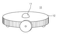
Translated fromKorean도 1은 본 발명에 사용되는 전방위 카메라를 탑재한 이동 로봇의 구성도이다.1 is a configuration diagram of a mobile robot equipped with an omnidirectional camera used in the present invention.
도 2는 도 1의 전방위 카메라의 간략한 구성도이다.FIG. 2 is a schematic configuration diagram of the omnidirectional camera of FIG. 1.
도 3은 본 발명의 실시예에 따른 로봇의 위치결정시스템의 제어블록도이다.3 is a control block diagram of a positioning system of a robot according to an embodiment of the present invention.
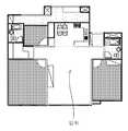
도 4는 도 1의 전방위 카메라를 이용하여 획득한 전방위 영상이다.4 is an omnidirectional image obtained by using the omnidirectional camera of FIG. 1.
도 5는 도 4의 전방위 영상의 수평면선을 나타낸 도이다.5 is a diagram illustrating a horizontal plane line of the omnidirectional image of FIG. 4.
도 6은 본 발명의 실시예에 따른 로봇의 위치결정시스템의 개념도이다.6 is a conceptual diagram of a positioning system of a robot according to an embodiment of the present invention.
도 7은 본 발명의 실시예에 따른 로봇의 위치결정방법에 대한 제어흐름도이다.7 is a control flowchart of the positioning method of the robot according to an embodiment of the present invention.
도 8은 로봇의 수평면선과 기준노드의 수평면선의 모서리 추출을 설명하기 위한 도이다.8 is a view for explaining the edge extraction of the horizontal plane of the robot and the horizontal plane of the reference node.
도 9는 로봇의 수평면선과 기준노드의 수평면선의 모서리 매칭을 설명하기 위한 도이다.9 is a view for explaining the corner matching of the horizontal plane line of the robot and the horizontal plane line of the reference node.
도 10은 로봇의 수평면선 변형을 설명하기 위한 도이다.10 is a view for explaining the horizontal line deformation of the robot.
도 11은 로봇이 위치 가능한 전 영역에 대하여 일정 입자를 랜덤하게 뿌리는 것을 설명하기 위한 도이다.FIG. 11 is a diagram for explaining that the robot randomly sprays a certain particle over the entire area where the robot can be located. FIG.
도 12는 본 발명에 사용된 입자 필터링 기법에 의해 도 11에서 뿌려진 입자가 한 곳에 모인 것을 설명하기 위한 도이다.FIG. 12 is a view for explaining that particles scattered in FIG. 11 are gathered in one place by the particle filtering technique used in the present invention.
*도면의 주요 기능에 대한 부호의 설명*[Description of the Reference Numerals]
10 : 로봇11 : 전방위 카메라10: robot 11: omnidirectional camera
20 : 영상처리부30 : 고속푸리에변환부20: image processing unit 30: high speed Fourier transform unit
40 : 저장부50 : 제어부40: storage unit 50: control unit
60 : 전방위카메라부60: omnidirectional camera
본 발명은 로봇의 위치 결정방법에 관한 것으로, 더욱 상세하게는 전방위 영상을 얻기 위한 전방위 카메라를 이용한 로봇의 위치 결정방법에 관한 것이다.The present invention relates to a method for positioning a robot, and more particularly, to a method for positioning a robot using an omnidirectional camera for obtaining an omnidirectional image.
일반적으로, 전방위 카메라는 전방향의 영상을 얻기 위한 것으로, 카메라 주변의 360도의 영상을 얻을 수 있다.In general, the omnidirectional camera is for obtaining an omnidirectional image, and can obtain an image of 360 degrees around the camera.
최근에는 이러한 전방위 카메라를 이동 로봇에 장착하여 로봇의 현재위치를 인식하는데 사용하고 있다.Recently, such a omnidirectional camera is mounted on a mobile robot and used to recognize the current position of the robot.
이러한 전방위 카메라를 로봇에 설치하여 로봇의 위치인식에 사용하는 방법은 일본 공개특허공보 특개평 10-160463호(공개일 1998년 6월 19일)에 기재된 것과 같이, 이동 공간 내의 임의의 위치에 여러 개의 노드를 정하고, 전방위카메라를 탑 재한 이동 로봇을 각 노드로 이동시켜 각 노드에서의 전방위 영상을 저장한다. 그 후 이동 로봇을 임의의 위치로 이동시켜 임의의 위치에 대한 전방위 영상을 획득한 후 획득한 전방위 영상과 이미 저장된 각 노드의 전방위 영상사이의 유사도를 측정하여 현재의 위치를 노드 기점으로 추정하여 인식한다.A method of installing such an omnidirectional camera in a robot and using it for position recognition of the robot is described in several publications at arbitrary positions in a moving space, as described in Japanese Patent Application Laid-Open No. 10-160463 (published June 19, 1998). The number of nodes is determined, and the mobile robot equipped with the omnidirectional camera is moved to each node to store the omnidirectional image from each node. After that, the mobile robot is moved to an arbitrary position to obtain an omnidirectional image of an arbitrary position, and then the similarity is measured between the acquired omnidirectional image and the previously stored omnidirectional image of each node. do.
그러나, 이러한 종래방법에서는 로봇의 현재 전방위 영상과 이미 저장된 각 노드의 전방위 영상간의 유사도를 측정하기 위하여 SAD(Sum of Absolute Differences ; SAD) 상관값(Correlation)을 사용하는데, 이 SAD(Sum of Absolute Differences ; SAD) 상관값(Correlation)을 이용한 방식은 이동 로봇의 각각의 회전각에 대하여 획득한 전방위 영상과 각 노드의 전방위 영상간의 영상차이를 일일이 비교하는 방식이므로 노드 수가 많아질수록 그 계산량이 기하급수적으로 증가하게 되기 때문에 사실상 실시간 위치인식이 불가능할 뿐만 아니라, 계산량 증가로 인한 오차 누적으로 인해 로봇이 어느 노드 부근인지를 정확히 알기 어려운 문제점이 있다.However, this conventional method uses SAD (Sum of Absolute Differences; Correlation) to measure the similarity between the current omnidirectional image of the robot and the previously stored omnidirectional image of each node. ; SAD) Correlation is a method that compares the image difference between the omnidirectional image obtained for each rotation angle of the mobile robot and the omnidirectional image of each node. In fact, not only real-time position recognition is impossible, but also due to error accumulation due to an increase in computation amount, it is difficult to know exactly which node the robot is near.
또한, 종래방법은 로봇의 위치를 인식함에 있어서, 로봇의 정확한 위치를 인식하는 것이 아니라, 로봇이 어느 노드 근처인지만을 추정할 수밖에 없어 로봇의 정확한 위치를 알 수 없는 문제점이 있다.In addition, in the conventional method of recognizing the position of the robot, it is not only to recognize the exact position of the robot, but only to estimate which node the robot is located, there is a problem that the exact position of the robot is not known.
본 발명은 전술한 문제점을 해결하기 위한 것으로, 본 발명의 목적은 로봇의 전방위 영상과 지도상의 기준노드의 영상간의 상관계수 추출을 보다 간편하면서도 고속 처리 가능하게 하여 기준노드를 기점으로 로봇의 위치를 보다 쉽고 빨리 인식 할 수 있는 로봇의 위치 결정방법을 제공하는 것이다.SUMMARY OF THE INVENTION The present invention has been made to solve the above-mentioned problems, and an object of the present invention is to extract the correlation coefficient between the omnidirectional image of the robot and the image of the reference node on the map more easily and at a high speed, thereby positioning the robot based on the reference node. It is to provide a robot positioning method that can be recognized more easily and quickly.
또한, 본 발명의 다른 목적은 로봇의 전방위 영상과 지도상의 기준노드의 영상간의 상관계수를 기반으로 한 입자 필터링의 확률적 접근에 의해 위치 오차 및 노이즈에 둔감하게 하여 로봇의 위치를 보다 정확하게 인식할 수 있고 로봇의 위치가 갑자기 변하는 상황에서도 대응이 가능하게 할 수 있는 로봇의 위치 결정방법을 제공하는 것이다.In addition, another object of the present invention is to be insensitive to position error and noise by probabilistic approach of particle filtering based on the correlation coefficient between the omnidirectional image of the robot and the image of the reference node on the map to more accurately recognize the position of the robot. It is possible to provide a robot positioning method capable of responding to a situation in which the position of the robot suddenly changes.
전술한 목적을 달성하기 위한 본 발명에 따른 전방위 영상을 이용한 로봇 위치 결정방법은 로봇의 전방위 영상을 획득하는 단계와, 상기 획득된 전방위 영상의 임의의 수평면선을 추출하는 단계와, 상기 추출된 로봇의 수평면선과 미리 저장된 복수노드의 수평면선사이의 상관계수를 고속 푸리에 변환에 기반하여 산출하는 단계와, 상기 산출된 상관계수가 미리 설정된 값 이상인 노드를 선택하는 단계와, 상기 선택된 노드를 기점으로 상기 로봇의 위치를 인식하는 단계를 포함하는 것을 특징으로 한다.In order to achieve the above object, a robot positioning method using an omnidirectional image according to the present invention includes obtaining an omnidirectional image of a robot, extracting an arbitrary horizontal plane line of the obtained omnidirectional image, and extracting the robot. Calculating a correlation coefficient between a horizontal plane line and a horizontal plane line of a plurality of nodes based on a fast Fourier transform; selecting a node having the calculated correlation coefficient greater than or equal to a preset value; and starting from the selected node Recognizing the location of the characterized in that it comprises.
또한, 본 발명의 다른 전방위 영상을 이용한 로봇의 위치결정방법은 로봇의 전방위 영상을 획득하는 단계와, 상기 획득된 전방위 영상의 임의의 수평면선을 추출하는 단계와, 상기 추출된 로봇의 수평면선과 미리 저장된 복수노드의 수평면선사이의 상관계수를 고속 푸리에 변환에 기반하여 산출하는 단계와, 상기 산출된 상관계수를 기반으로 한 입자 필터링의 확률적 접근에 의해 상기 로봇의 위치를 인식하는 단계를 포함하는 것을 특징으로 한다.In addition, the positioning method of the robot using another omnidirectional image of the present invention comprises the steps of acquiring the omnidirectional image of the robot, extracting any horizontal plane line of the obtained omnidirectional image, and the horizontal plane line of the extracted robot Calculating a correlation coefficient between horizontal plane lines of a plurality of nodes stored on the basis of a fast Fourier transform; and recognizing the position of the robot by a probabilistic approach of particle filtering based on the calculated correlation coefficient. It features.
이하에서는 본 발명의 바람직한 실시예를 본 도면을 참조하여 상세하게 설명하도록 한다.Hereinafter, preferred embodiments of the present invention will be described in detail with reference to the drawings.
도 1 및 도 2에 도시된 바와 같이, 본 발명에 사용되는 전방위 카메라를 탑재한 이동 로봇(10)은 전방위 카메라와 이 전방위 카메라가 장착된 로봇본체(12)로 이루어지고, 전방위 카메라는 전방위 렌즈(11a)와 CCD 소자(11b)로 구성된다.1 and 2, the
도 2와 같이, 전방위 카메라 전면부에는 곡면 거울이 장착되며, 이 곡면의 거울에 의해 굴절된 카메라 주변의 360도 영상이 획득된다. 화살방향과 같이, 공간상의 점 Xmir가, 곡면 거울 면의 점 xmir에서 반사되어 CCD 소자(11b)에 결상되고, 최종적으로 영상 면의 점 ximg로 나타나게 된다. 이렇게 전방위 카메라를 중심으로 주변의 360□에 대한 영상을 얻을 수 있게 된다.As shown in FIG. 2, a curved mirror is mounted on the omnidirectional camera, and a 360 degree image around the camera refracted by the curved mirror is obtained. As in the direction of the arrow, the point Xmir in space is reflected from the point xmir on the curved mirror surface to form an image on the
본 발명은 상기한 전방위 카메라로부터 획득한 전방위 영상과 영상지도상의 수평면선들을 대상으로 후술하는 고속 푸리에 변환(Fast Fourier Transform ; FFT)방식에 의해 고속 계산되는 상관계수(Correlation Coefficient) 추출법과 이 상관계수 추출법에 의해 추출된 상관계수를 이용한 입자 필터링 기법에 의해서 로봇(10)의 정확한 위치를 추정하여 인식하게 된다. 이때, 수평면선은 전방위 영상 중 표면과 평행한 면의 영상으로 항상 같은 방향을 가르킨다.According to the present invention, a correlation coefficient extraction method and a fast correlation coefficient extraction method, which are described by a fast Fourier transform (FFT) method described later, are used for the omnidirectional image obtained from the omnidirectional camera and the horizontal plane lines on the image map. The exact position of the
이를 위해 본 발명의 로봇(10) 위치 결정시스템은 도 3에 도시된 바와 같이, 상기한 전방위 카메라를 탑재한 로봇(10)은 전반적인 제어를 수행하는 제어부(50)를 구비한다. 이 제어부(50)에는 전방위카메라부(60)와, 영상처리부(20)와, 고속 푸리에 변환부(30)(Fast Fourier Transform module ; FFT 모듈) 및 저장부(40)가 전기적으로 연결된다.To this end, the
영상처리부(20)는 전방위 카메라에 의해 획득한 카메라 주변의 전방위 영상에 대한 영상 전처리를 수행하기 위한 것으로, 도 4의 전방위 영상의 무의미한 부분을 잘라내고 나머지 도너스 형태의 원형에 히스토그램 평활화를 수행하는 방식으로 영상을 전처리하여 전방위 영상을 밝기에 상관없도록 조명에 둔감하게 한다.The
제어부(50)는 영상처리부(20)에 의해 전처리 된 영상에서 도 5에서 영상 내에 원주로 표시된 것과 같이, 영상 내의 수평면에 대응하는 수평면선을 추출한다.The
이때, 고속 푸리에 변환의 특성상 수평면선의 해상도(RGB)는 2의 제곱승이 바람직하며, 수평면선은 전방위 영상의 원점을 기준으로 미리 설정된 위치로 미리 설정된다.At this time, the resolution RGB of the horizontal plane line is preferably a power of 2, and the horizontal plane line is preset to a preset position based on the origin of the omnidirectional image.
고속 푸리에 변환부(30)는 푸리에 변환(Fourier transform)은 주파수 영역과 시간 영역 사이에 수치적 연속열의 표현들을 변환하는데 사용하는 수학적 연산으로, 일련의 시간 샘플을 취해 그 주파수 요소들을 측정하여 시간 샘플 연속열에 얼마나 많은 에너지가 나타나는지 다양한 주파수로 계산하는 것이다. 이러한 푸리에 변환을 고속화한 것이 고속 푸리에 변환이다. 푸리에 변환은 어느 길이의 해상도 연속 열도 계산할 수 있지만 고속 푸리에 변환의 이점을 최대한 활용하기 위해서는 앞서 설명한 바와 같이 그 수평면선의 해상도는 2의 제곱승이 될 필요가 있다.The fast Fourier
저장부(40)는 영상지도상의 여러 개의 기준노드에 대하여 각 수평면선을 미리 추출하여 저장하고 있다.The
제어부(50)는 고속 푸리에 변환부(30)를 이용하여 로봇(10)의 수평면선과 영상지도상의 각 기준노드의 수평면선간의 상관계수를 산출시 노이즈에 둔감하면서도 고속 처리 가능하다. 이는 고속 푸리에 변환을 이용하는 경우, 각 상관계수와 함께 회전각이 한꺼번에 자동 계산되기 때문에 종래와 같이 각각의 회전각마다 두 영상간의 상관값을 일일이 계산할 필요가 없어져 고속 계산이 가능하게 된다. 이로 인해 로봇(10)의 실시간 위치 구현이 가능하게 된다.The
제어부(50)는 다음의 식 [1]에 의해서 로봇(10)의 현재의 전방위 영상의 수평면선과 저장부(40)에 미리 저장된 각각의 기준노드의 수평면선사이의 상관계수를 산출한다.The

(여기서, ρ(τ)는 상관계수이고, τ는 회전각이고, Cxy는 크로스 상관값(Cross Correlation)이고, Cxx 및 Cyy는 상관값(Correlation)이다)(Where ρ (τ) is the correlation coefficient, τ is the rotation angle, Cxy is the Cross Correlation, and Cxx and Cyy are the Correlation)
상기 식 [1]에서 상관계수의 절대값이 1에 가까울수록 두 전방위 영상의 수평면선이 유사하다는 것을 나타낸다. 또한 Cxy는 크로스 상관값은 고속 푸리에 변환을 이용하여 구한다.In Equation [1], the closer the absolute value of the correlation coefficient is to 1, the more similar the horizontal plane lines of the two omnidirectional images are. In addition, Cxy is obtained by using a fast Fourier transform.
상기 제어부(50)는 상기한 식 [1]을 이용하여 로봇(10)의 현재 수평면선과 저장부(40)에 미리 저장된 각 기준노드의 수평면선간의 상관계수를 산출하고, 산출된 상관계수를 이용하여 로봇(10)이 각 기준노드 중 어느 노드 부근에 있는지를 정확히 알 수 있게 된다. 일예로, 로봇(10)은 상관계수 중 가장 큰 상관계수를 갖는 기준노드 부근에 있다는 식으로 로봇(10)의 위치를 인식하게 된다.The
하지만, 상기한 방식만으로는 위치 오차와 노이즈 등의 에러요인에 의해 로봇(10)의 위치가 정확하지 않을 수 있기 때문에 보다 정확한 위치인식을 위해서는 위치 오차와 노이즈 등의 에러요인을 배제하기 위한 과정을 수행하는 것이 바람직하다.However, since the position of the
이를 위해 상기 제어부(50)는 식 [1]에 의해 산출된 상관계수 들 중 상관관계가 높아 상관계수가 큰 M개의 노드를 선택하고, 선택된 M개의 노드에 대하여 각 노드의 수평면선에 대하여 현재 수평면선을 변형하여 노이즈에 둔감한 상관계수를 구하고, 구한 각 노드와의 상관계수를 이용한 입자필터링에 의해 로봇(10)의 현재 위치를 인식한다.To this end, the
좀더 자세히 살펴보면, 본 발명은 도 6에 도시된 바와 같이, 상기한 전방위 카메라로부터 획득한 로봇(10)의 전방위 영상에서 수평면선을 추출하고, 추출된 로봇(10)의 수평면선과, 영상지도상의 각 기준노드들에 대하여 미리 저장된 수평면선들을 대상으로 후술하는 고속 푸리에 변환(Fast Fourier Transform ; FFT)방식에 의해 고속 계산되는 상관계수(Correlation Coefficient)를 산출하고, 산출된 상관계수를 기반으로 하고, 로봇(10)의 구동명령과 로봇(10)의 현위치에 따른 입자 필터링 기법에 의해 로봇(10)의 정확한 현위치를 추정하여 인식하게 된다. 이때, 수평면선은 길이방향으로 여러 해상도(RGB)값을 가진다.In more detail, as shown in FIG. 6, the present invention extracts a horizontal plane line from an omnidirectional image of the
도 7은 본 발명의 실시예에 따른 로봇(10)의 위치 결정방법에 대한 제어흐름도이다. 도 7을 살펴보면, 먼저, 단계 S100에서 제어부(50)는 전방위 카메라를 이 용하여 로봇(10)의 전방위 영상을 획득하고, 단계 S110에서, 획득된 전방위 영상을 전처리한다.7 is a control flowchart of the positioning method of the
전방위 영상을 전처리한 후 단계 S120에서 전방위 영상에서 수평면선을 추출하고, 단계 S130에서, 고속 푸리에 변환방식에 기반하여 상술한 식 [1]을 이용하여 추출된 수평면선과 각 기준노드의 수평면선사이의 상관계수(제1상관계수)를 산출한다.After preprocessing the omnidirectional image, in step S120, the horizontal plane line is extracted from the omnidirectional image, and in step S130, the correlation between the horizontal plane line extracted using the above-described equation [1] based on the fast Fourier transform method and the horizontal plane line of each reference node The coefficient (first correlation coefficient) is calculated.
제1상관계수를 산출한 후 단계 S140에서 산출된 제1상관계수 중 상관계수값이 미리 설정된 값보다 높은 M개의 노드를 선택하고, 단계 S150에서, M개의 후보노드에 대하여 공간상의 같은 물체는 수평면상의 같은 곳에 위치하도록 현재 수평면을 변형시킨다. 이는 위치 오차 및 노이즈에 둔감하게 하기 위함으로 먼저, 도 8과 같이, 로봇(10)의 수평면선(Current Line)(200)과 각 후보노드의 수평면선(Landmark Line)(100)에 대하여 원으로 그린 것과 같이 두 수평면상의 모서리를 추출한다. 이때 모서리는 수평면선상의 각 해상도가 미리 설정된 값 이상 변화하는 끝점을 말한다. 도 9와 같이, 추출된 로봇(10)의 수평면선(200)과 선택된 후보노드의 수평면선(100)의 모서리를 매칭한다. 그런 후 도 10과 같이, 매칭된 모서리를 기준으로 현재의 수평면선을 변형하여 공간상의 같은 물체가 수평면상에 같은 곳에 위치하도록 변형된 현재의 수평면선(Wrapped Current Line)(300)과 같이 로봇(10)의 현재 수평면선을 변형시킨다.After calculating the first correlation coefficient, among the first correlation coefficients calculated in step S140, M nodes having a correlation coefficient value higher than a preset value are selected. In step S150, the same object in space with respect to M candidate nodes is a horizontal plane. Transform the current horizontal plane so that it is in the same place on the top of the jacket. This is insensitive to position error and noise. First, as shown in FIG. 8, a circle is made with respect to the
로봇(10)의 현재 수평면선을 변형시킨 후 단계 S160에서 변형된 로봇(10)의 현재 수평면선과 M개의 후보노드의 수평면선사이의 상관계수(제2상관계수)를 다시 산출하고, 단계 S170에서, 변형된 로봇(10)의 현재 수평면선과 M개의 후보노드의 수평면선사이의 상관계수(제2상관계수)가 높은 노드 N개(M>N)를 선택한다. 이 과정을 통하여 이동물체로 인하여 발생되는 위치 오차 및 각종 노이즈에 의한 위치 오차가 제거되어 로봇(10)이 M개보다 좁혀진 N개의 노드 부근에 있다는 것을 보다 정확하고 신뢰성이 있게 알 수 있게 된다.After transforming the current horizontal plane line of the
상기한 방식만으로는 로봇(10)이 어느 노드부근에 있는지 만을 알 수 있을 뿐 지도상의 어느 위치에 정확히 있는지를 알 수 없기 때문에 입자 필터링의 확률적 접근에 의해 로봇(10)의 현재위치를 정확히 알 수 있도록 하기 위하여 단계 180에서 선택된 N개의 노드를 중심으로 상관계수(제2상관계수)를 이용하여 입자 생성하여 로봇(10)이 위치 가능한 지도상의 전역에 랜덤하게 뿌리고, 단계 S190에서 각 입자의 확률값을 계산하여 로봇(10)의 현재의 위치를 추정하게 된다. 즉, 추정된 로봇(10)의 전 위치(Xt-1)와 로봇(10)의 구동 명령(Ut)에 의해 예상되는 로봇(10)의 위치 가능한 지도상의 전역에 입자를 골고루 뿌린다. 입자의 분포는 도 11에 도시된 바와 같이, 가우시안 분포를 가지며, 입자의 가우시안 분포의 표준 편차는 Xt-1의 오차, 이동 오차 등에 의해서 정해진다. 그리고 사용자가 로봇(10)을 다른 위치로 강제 이동시키는 것과 같이 로봇(10)의 위치가 갑자기 변하는 키드냅(Kidnap) 문제에 대응하기 위해서 입자를 전 영역에 대하여 랜덤으로 퍼트린다.Since only the above method can know only which node is located near which node, it cannot know exactly where it is on the map. Therefore, the present position of the
각 입자에 로봇(10)이 위치할 확률은 각 노드와의 상관계수를 기반으로 하여 계산된다. 이 확률값을 기준으로 로봇(10)의 현재위치(Xt) 입자를 재샘플링을 한다. 이렇게 하여 도 12에 도시된 바와 같이, 로봇(10)의 현재위치를 추정할 수 있 게 된다. 즉, 노드의 상관계수가 높을수록 그 곳에 위치할 확률이 크기 때문에 각 입자에 대하여 가중치를 고려하여 부여하고, 가중치가 고려된 값을 기반으로 뿌려진 입자를 무작위 추출한다. 이러한 과정을 반복하되, 두 번째로 입자를 뿌릴 때는 기존 위치에 대부분이 뿌려지게 되고, 나머지 전역에 대하여 약간의 입자가 뿌려지게 된다. 이와 같은 과정을 반복하게 되면, 결국 도 12와 같이, 입자가 한 곳에 모이게 되며, 모여진 입자 중 어느 입자를 추출하게 되더라도 거의 동일한 위치를 나타나게 되기 때문에 결국 로봇(10)의 현재위치를 알 수 있게 된다.The probability that the
이상에서 상세히 설명한 바와 같이, 본 발명은 전방위 카메라를 이용하여 카메라 주변의 360도 영상을 획득하고, 획득된 360도 영상의 수평면선에 대한 1차원 원형 영상과 미리 저장된 지도상의 각 노드의 수평면선사이의 상관계수를 고속 푸리에 변환(Fast Fourier Transform ; FFT) 기법을 이용함으로써 빠른 속도로 상관계수를 계산할 수 있어 로봇의 현재위치가 어느 노드에 부근인지를 보다 빨리 인식할 수 있는 효과가 있다.As described in detail above, the present invention obtains a 360 degree image around the camera by using an omnidirectional camera, and between the one-dimensional circular image of the horizontal plane line of the obtained 360 degree image and the horizontal plane line of each node on the pre-stored map. By using the Fast Fourier Transform (FFT) technique, the correlation coefficient can be calculated at a high speed, so that it is possible to recognize which node the robot is in close proximity to.
또한, 본 발명은 고속 푸리에 변환(Fast Fourier Transform ; FFT) 기법을 이용하여 고속 계산된 상관계수를 기반으로 하여 입자 필터링을 통해 로봇의 전역 위치를 보다 신속하고 정확히 인식할 수 있는 효과가 있고 로봇의 위치가 갑자기 변하는 키드냅(Kidnap) 문제도 해결이 가능할 뿐만 아니라, 하다. 로봇이 어느 노드 부근인지에 대한 신뢰성을 향상시킬 수 있는 효과가 있다.In addition, the present invention has the effect of quickly and accurately recognizing the global position of the robot through particle filtering based on a fast calculated correlation coefficient using the Fast Fourier Transform (FFT) technique. The Kidnap problem, which changes its position suddenly, can be solved as well. There is an effect that can improve the reliability of which node the robot is near.
또한, 고속 푸리에 변환(Fast Fourier Transform ; FFT) 기법을 이용하여 고 속 계산된 상관계수 중 상관관계가 높은 노드들에 대하여 이 노드의 수평면선에 대하여 로봇의 수평면선을 변형하여 노이즈에 둔감하고 보다 정확한 상관계수를 계산할 수 있다.In addition, the high-correlation nodes computed using the Fast Fourier Transform (FFT) technique are transformed into the robot's horizontal plane with respect to the horizontal plane of the node and are insensitive to noise. Accurate correlation coefficients can be calculated.
또한, 본 발명은 상기한 로봇 위치결정을 위해 사용되는 전방위 카메라는 낮은 단가로 인하여 로봇 위치 결정시스템을 저가로 구현 가능하여 기존의 고가 레이져 레인지 센서에 비하여 월등한 가격 경쟁력을 가지는 효과가 있다.In addition, the present invention, the omnidirectional camera used for the robot positioning can implement a robot positioning system at a low price due to the low unit cost has an excellent price competitiveness compared to the existing expensive laser range sensor.
또한, 본 발명은 실내에서 이동하는 로봇에 실시간 무표식 전역 위치 추정이 가능하고, 상관계수 오차에 둔감한 특성을 갖는다.In addition, the present invention is capable of real-time unmarked global position estimation for the robot moving in the room, and has a characteristic insensitive to the correlation coefficient error.
또한, 본 발명은 로봇의 위치인식을 위한 고속 계산이 가능하며, 제작되는 지도의 크기를 줄일 수 있는 효과가 있다.In addition, the present invention is capable of high-speed calculation for the position recognition of the robot, it is possible to reduce the size of the map produced.
Claims (16)
Translated fromKorean

Priority Applications (4)
| Application Number | Priority Date | Filing Date | Title |
|---|---|---|---|
| KR1020060093653AKR100966875B1 (en) | 2006-09-26 | 2006-09-26 | Robot positioning using omnidirectional image |
| US11/830,883US8498488B2 (en) | 2006-09-26 | 2007-07-31 | Method and apparatus to determine robot location using omni-directional image |
| CN2007101418999ACN101152718B (en) | 2006-09-26 | 2007-08-16 | Method and apparatus to determine robot location using omni-directional image |
| JP2007231617AJP4500838B2 (en) | 2006-09-26 | 2007-09-06 | Robot position determination method and apparatus using omnidirectional video |
Applications Claiming Priority (1)
| Application Number | Priority Date | Filing Date | Title |
|---|---|---|---|
| KR1020060093653AKR100966875B1 (en) | 2006-09-26 | 2006-09-26 | Robot positioning using omnidirectional image |
Publications (2)
| Publication Number | Publication Date |
|---|---|
| KR20080028185A KR20080028185A (en) | 2008-03-31 |
| KR100966875B1true KR100966875B1 (en) | 2010-06-29 |
Family
ID=39225023
Family Applications (1)
| Application Number | Title | Priority Date | Filing Date |
|---|---|---|---|
| KR1020060093653AExpired - Fee RelatedKR100966875B1 (en) | 2006-09-26 | 2006-09-26 | Robot positioning using omnidirectional image |
Country Status (4)
| Country | Link |
|---|---|
| US (1) | US8498488B2 (en) |
| JP (1) | JP4500838B2 (en) |
| KR (1) | KR100966875B1 (en) |
| CN (1) | CN101152718B (en) |
Cited By (3)
| Publication number | Priority date | Publication date | Assignee | Title |
|---|---|---|---|---|
| KR101811157B1 (en)* | 2013-12-19 | 2018-01-25 | 인텔 코포레이션 | Bowl-shaped imaging system |
| WO2018074903A1 (en)* | 2016-10-20 | 2018-04-26 | 엘지전자 주식회사 | Control method of mobile robot |
| US10442355B2 (en) | 2014-09-17 | 2019-10-15 | Intel Corporation | Object visualization in bowl-shaped imaging systems |
Families Citing this family (32)
| Publication number | Priority date | Publication date | Assignee | Title |
|---|---|---|---|---|
| US8209121B1 (en)* | 2007-10-10 | 2012-06-26 | Google Inc. | Registration of location data to street maps using hidden markov models, and application thereof |
| KR100926783B1 (en)* | 2008-02-15 | 2009-11-13 | 한국과학기술연구원 | A method for estimating the magnetic position of the robot based on the environment information including object recognition and recognized object |
| CN101509781B (en)* | 2009-03-20 | 2011-09-14 | 同济大学 | Walking robot positioning system based on monocular cam |
| TWI680928B (en) | 2009-04-10 | 2020-01-01 | 美商辛波提克有限責任公司 | Vertical lift system and method for transferring uncontained case unit to and from a multilevel storage structure |
| US8311285B2 (en)* | 2009-06-30 | 2012-11-13 | Mitsubishi Electric Research Laboratories, Inc. | Method and system for localizing in urban environments from omni-direction skyline images |
| US8249302B2 (en)* | 2009-06-30 | 2012-08-21 | Mitsubishi Electric Research Laboratories, Inc. | Method for determining a location from images acquired of an environment with an omni-directional camera |
| US8849036B2 (en)* | 2009-10-30 | 2014-09-30 | Yujin Robot Co., Ltd. | Map generating and updating method for mobile robot position recognition |
| KR101739996B1 (en)* | 2010-11-03 | 2017-05-25 | 삼성전자주식회사 | Moving robot and simultaneous localization and map-buliding method thereof |
| US8694152B2 (en) | 2010-12-15 | 2014-04-08 | Symbotic, LLC | Maintenance access zones for storage and retrieval systems |
| US9475649B2 (en) | 2010-12-15 | 2016-10-25 | Symbolic, LLC | Pickface builder for storage and retrieval systems |
| US9008884B2 (en) | 2010-12-15 | 2015-04-14 | Symbotic Llc | Bot position sensing |
| US10822168B2 (en) | 2010-12-15 | 2020-11-03 | Symbotic Llc | Warehousing scalable storage structure |
| US8908923B2 (en)* | 2011-05-13 | 2014-12-09 | International Business Machines Corporation | Interior location identification |
| TWI622540B (en) | 2011-09-09 | 2018-05-01 | 辛波提克有限責任公司 | Automated storage and handling system |
| KR101901586B1 (en)* | 2011-12-23 | 2018-10-01 | 삼성전자주식회사 | Apparatus for estimating the robot pose and method thereof |
| KR101997563B1 (en)* | 2012-09-04 | 2019-07-08 | 삼성전자주식회사 | Localization method for mobile object |
| CN103903219A (en)* | 2012-12-26 | 2014-07-02 | 联想(北京)有限公司 | Information processing method and system |
| KR102087595B1 (en)* | 2013-02-28 | 2020-03-12 | 삼성전자주식회사 | Endoscope system and control method thereof |
| TWI594933B (en) | 2013-03-15 | 2017-08-11 | 辛波提克有限責任公司 | Automated storage and retrieval system |
| KR102265424B1 (en) | 2013-03-15 | 2021-06-15 | 심보틱 엘엘씨 | Automated storage and retrieval system with integral secured personnel access zones and remote rover shutdown |
| TWI642028B (en) | 2013-03-15 | 2018-11-21 | 辛波提克有限責任公司 | Transportation system and automated storage and retrieval system with integral secured personnel access zones and remote rover shutdown |
| CN103273496B (en)* | 2013-05-08 | 2015-07-15 | 长沙长泰机器人有限公司 | Workpiece positioning method in robot transportation system by means of intelligent camera |
| CN105705441B (en) | 2013-09-13 | 2018-04-10 | 西姆伯蒂克有限责任公司 | Autonomous transport car, the method for storing and fetching system and selection face being transmitted in the system |
| KR101483549B1 (en)* | 2013-12-03 | 2015-01-16 | 전자부품연구원 | Method for Camera Location Estimation with Particle Generation and Filtering and Moving System using the same |
| US10373335B1 (en)* | 2014-07-10 | 2019-08-06 | Hrl Laboratories, Llc | System and method for location recognition and learning utilizing convolutional neural networks for robotic exploration |
| US11320828B1 (en) | 2018-03-08 | 2022-05-03 | AI Incorporated | Robotic cleaner |
| US11254002B1 (en) | 2018-03-19 | 2022-02-22 | AI Incorporated | Autonomous robotic device |
| US11454981B1 (en) | 2018-04-20 | 2022-09-27 | AI Incorporated | Versatile mobile robotic device |
| US11340079B1 (en) | 2018-05-21 | 2022-05-24 | AI Incorporated | Simultaneous collaboration, localization, and mapping |
| US11548159B1 (en) | 2018-05-31 | 2023-01-10 | AI Incorporated | Modular robot |
| US11199853B1 (en) | 2018-07-11 | 2021-12-14 | AI Incorporated | Versatile mobile platform |
| CN111203877B (en)* | 2020-01-13 | 2021-12-28 | 广州大学 | Climbing building waste sorting robot system, control method, device and medium |
Citations (4)
| Publication number | Priority date | Publication date | Assignee | Title |
|---|---|---|---|---|
| JPH0566831A (en)* | 1991-04-30 | 1993-03-19 | Shinko Electric Co Ltd | Running control method in moving robot system |
| KR20060046842A (en)* | 2004-11-12 | 2006-05-18 | 학교법인 포항공과대학교 | Efficient Edge Information Calculation Method for Position Recognition of Mobile Robot |
| KR20060081673A (en)* | 2006-05-25 | 2006-07-13 | 한국정보통신대학교 산학협력단 | Sensor network based broad security robot system and method |
| JP2006195969A (en)* | 2004-12-14 | 2006-07-27 | Honda Motor Co Ltd | Moving path generation device for autonomous mobile robot |
Family Cites Families (11)
| Publication number | Priority date | Publication date | Assignee | Title |
|---|---|---|---|---|
| JP2853283B2 (en)* | 1989-09-18 | 1999-02-03 | 三菱電機株式会社 | Omnidirectional observation device |
| US5920337A (en)* | 1994-12-27 | 1999-07-06 | Siemens Corporate Research, Inc. | Omnidirectional visual image detector and processor |
| JP3641335B2 (en) | 1996-12-03 | 2005-04-20 | シャープ株式会社 | Position detection method using omnidirectional vision sensor |
| JP2004132933A (en)* | 2002-10-15 | 2004-04-30 | Japan Science & Technology Agency | Active sensor position / posture estimation method and device, and active sensor position / posture estimation program |
| US7162338B2 (en)* | 2002-12-17 | 2007-01-09 | Evolution Robotics, Inc. | Systems and methods for computing a relative pose for global localization in a visual simultaneous localization and mapping system |
| JP3879848B2 (en)* | 2003-03-14 | 2007-02-14 | 松下電工株式会社 | Autonomous mobile device |
| JP4352214B2 (en) | 2003-04-23 | 2009-10-28 | 清水建設株式会社 | 3D position and orientation image estimation method |
| US8896660B2 (en)* | 2003-05-30 | 2014-11-25 | Alcatel Lucent | Method and apparatus for computing error-bounded position and orientation of panoramic cameras in real-world environments |
| KR100552691B1 (en)* | 2003-09-16 | 2006-02-20 | 삼성전자주식회사 | Method and apparatus for estimating magnetic position and azimuth of mobile robot |
| US7689321B2 (en)* | 2004-02-13 | 2010-03-30 | Evolution Robotics, Inc. | Robust sensor fusion for mapping and localization in a simultaneous localization and mapping (SLAM) system |
| JP2006220521A (en)* | 2005-02-10 | 2006-08-24 | Hitachi Ltd | Program for executing self-position measuring device and self-position measuring method |
- 2006
- 2006-09-26KRKR1020060093653Apatent/KR100966875B1/ennot_activeExpired - Fee Related
- 2007
- 2007-07-31USUS11/830,883patent/US8498488B2/ennot_activeExpired - Fee Related
- 2007-08-16CNCN2007101418999Apatent/CN101152718B/ennot_activeExpired - Fee Related
- 2007-09-06JPJP2007231617Apatent/JP4500838B2/ennot_activeExpired - Fee Related
Patent Citations (4)
| Publication number | Priority date | Publication date | Assignee | Title |
|---|---|---|---|---|
| JPH0566831A (en)* | 1991-04-30 | 1993-03-19 | Shinko Electric Co Ltd | Running control method in moving robot system |
| KR20060046842A (en)* | 2004-11-12 | 2006-05-18 | 학교법인 포항공과대학교 | Efficient Edge Information Calculation Method for Position Recognition of Mobile Robot |
| JP2006195969A (en)* | 2004-12-14 | 2006-07-27 | Honda Motor Co Ltd | Moving path generation device for autonomous mobile robot |
| KR20060081673A (en)* | 2006-05-25 | 2006-07-13 | 한국정보통신대학교 산학협력단 | Sensor network based broad security robot system and method |
Cited By (4)
| Publication number | Priority date | Publication date | Assignee | Title |
|---|---|---|---|---|
| KR101811157B1 (en)* | 2013-12-19 | 2018-01-25 | 인텔 코포레이션 | Bowl-shaped imaging system |
| US10210597B2 (en) | 2013-12-19 | 2019-02-19 | Intel Corporation | Bowl-shaped imaging system |
| US10442355B2 (en) | 2014-09-17 | 2019-10-15 | Intel Corporation | Object visualization in bowl-shaped imaging systems |
| WO2018074903A1 (en)* | 2016-10-20 | 2018-04-26 | 엘지전자 주식회사 | Control method of mobile robot |
Also Published As
| Publication number | Publication date |
|---|---|
| US8498488B2 (en) | 2013-07-30 |
| JP2008083045A (en) | 2008-04-10 |
| KR20080028185A (en) | 2008-03-31 |
| CN101152718B (en) | 2011-09-28 |
| US20080075357A1 (en) | 2008-03-27 |
| CN101152718A (en) | 2008-04-02 |
| JP4500838B2 (en) | 2010-07-14 |
Similar Documents
| Publication | Publication Date | Title |
|---|---|---|
| KR100966875B1 (en) | Robot positioning using omnidirectional image | |
| US8588512B2 (en) | Localization method for a moving robot | |
| Kang et al. | Automatic targetless camera–lidar calibration by aligning edge with gaussian mixture model | |
| KR100791389B1 (en) | Distance measuring device and method using structured light | |
| WO2009142841A2 (en) | Rectangular table detection using hybrid rgb and depth camera sensors | |
| JP4561346B2 (en) | Vehicle motion estimation device and moving object detection device | |
| JP2002352225A (en) | Obstacle detection apparatus and method | |
| CN109001757A (en) | A kind of parking space intelligent detection method based on 2D laser radar | |
| JP2011113313A (en) | Attitude estimation device | |
| JP2006090957A (en) | Moving object surrounding object detection apparatus and moving object surrounding object detection method | |
| KR101645322B1 (en) | System and method for detecting lane using lane variation vector and cardinal spline | |
| JP2015059808A (en) | Object monitoring device and object monitoring system | |
| KR101594113B1 (en) | Scale-aware image patch tracking device and method | |
| JP7290104B2 (en) | SELF-LOCATION ESTIMATING DEVICE, METHOD AND PROGRAM | |
| US5142659A (en) | Estimation of local surface geometry from relative range images for object recognition | |
| CN112712476A (en) | Denoising method and denoising device for TOF (time of flight) ranging and TOF camera | |
| CN109635692B (en) | Scene Re-identification Method Based on Ultrasonic Sensor | |
| JP2003317106A (en) | Roadway recognition device | |
| JP2003281503A (en) | 3D object image recognition device | |
| KR101997563B1 (en) | Localization method for mobile object | |
| KR101906999B1 (en) | Apparatus and method for calculating distance between vehicle and object of adjacent lane | |
| WO2014192061A1 (en) | Image processing device, image processing method, and image processing program | |
| Zhang et al. | Multi-sensor approach for people detection | |
| US20240144483A1 (en) | Method and system for recognizing objects, which are represented in an image by means of a point cloud | |
| KR101747350B1 (en) | Method for recognizing coordinates of object for visual servoing |
Legal Events
| Date | Code | Title | Description |
|---|---|---|---|
| PA0109 | Patent application | St.27 status event code:A-0-1-A10-A12-nap-PA0109 | |
| A201 | Request for examination | ||
| PA0201 | Request for examination | St.27 status event code:A-1-2-D10-D11-exm-PA0201 | |
| PG1501 | Laying open of application | St.27 status event code:A-1-1-Q10-Q12-nap-PG1501 | |
| D13-X000 | Search requested | St.27 status event code:A-1-2-D10-D13-srh-X000 | |
| D14-X000 | Search report completed | St.27 status event code:A-1-2-D10-D14-srh-X000 | |
| E902 | Notification of reason for refusal | ||
| PE0902 | Notice of grounds for rejection | St.27 status event code:A-1-2-D10-D21-exm-PE0902 | |
| E13-X000 | Pre-grant limitation requested | St.27 status event code:A-2-3-E10-E13-lim-X000 | |
| P11-X000 | Amendment of application requested | St.27 status event code:A-2-2-P10-P11-nap-X000 | |
| P13-X000 | Application amended | St.27 status event code:A-2-2-P10-P13-nap-X000 | |
| E90F | Notification of reason for final refusal | ||
| PE0902 | Notice of grounds for rejection | St.27 status event code:A-1-2-D10-D21-exm-PE0902 | |
| E13-X000 | Pre-grant limitation requested | St.27 status event code:A-2-3-E10-E13-lim-X000 | |
| P11-X000 | Amendment of application requested | St.27 status event code:A-2-2-P10-P11-nap-X000 | |
| P13-X000 | Application amended | St.27 status event code:A-2-2-P10-P13-nap-X000 | |
| R17-X000 | Change to representative recorded | St.27 status event code:A-3-3-R10-R17-oth-X000 | |
| E701 | Decision to grant or registration of patent right | ||
| PE0701 | Decision of registration | St.27 status event code:A-1-2-D10-D22-exm-PE0701 | |
| GRNT | Written decision to grant | ||
| PR0701 | Registration of establishment | St.27 status event code:A-2-4-F10-F11-exm-PR0701 | |
| PR1002 | Payment of registration fee | St.27 status event code:A-2-2-U10-U11-oth-PR1002 Fee payment year number:1 | |
| PG1601 | Publication of registration | St.27 status event code:A-4-4-Q10-Q13-nap-PG1601 | |
| R18-X000 | Changes to party contact information recorded | St.27 status event code:A-5-5-R10-R18-oth-X000 | |
| FPAY | Annual fee payment | Payment date:20130522 Year of fee payment:4 | |
| PR1001 | Payment of annual fee | St.27 status event code:A-4-4-U10-U11-oth-PR1001 Fee payment year number:4 | |
| FPAY | Annual fee payment | Payment date:20140522 Year of fee payment:5 | |
| PR1001 | Payment of annual fee | St.27 status event code:A-4-4-U10-U11-oth-PR1001 Fee payment year number:5 | |
| FPAY | Annual fee payment | Payment date:20150522 Year of fee payment:6 | |
| PR1001 | Payment of annual fee | St.27 status event code:A-4-4-U10-U11-oth-PR1001 Fee payment year number:6 | |
| FPAY | Annual fee payment | Payment date:20160518 Year of fee payment:7 | |
| PR1001 | Payment of annual fee | St.27 status event code:A-4-4-U10-U11-oth-PR1001 Fee payment year number:7 | |
| FPAY | Annual fee payment | Payment date:20170522 Year of fee payment:8 | |
| PR1001 | Payment of annual fee | St.27 status event code:A-4-4-U10-U11-oth-PR1001 Fee payment year number:8 | |
| FPAY | Annual fee payment | Payment date:20180518 Year of fee payment:9 | |
| PR1001 | Payment of annual fee | St.27 status event code:A-4-4-U10-U11-oth-PR1001 Fee payment year number:9 | |
| PR1001 | Payment of annual fee | St.27 status event code:A-4-4-U10-U11-oth-PR1001 Fee payment year number:10 | |
| PR1001 | Payment of annual fee | St.27 status event code:A-4-4-U10-U11-oth-PR1001 Fee payment year number:11 | |
| PC1903 | Unpaid annual fee | St.27 status event code:A-4-4-U10-U13-oth-PC1903 Not in force date:20210623 Payment event data comment text:Termination Category : DEFAULT_OF_REGISTRATION_FEE | |
| PC1903 | Unpaid annual fee | St.27 status event code:N-4-6-H10-H13-oth-PC1903 Ip right cessation event data comment text:Termination Category : DEFAULT_OF_REGISTRATION_FEE Not in force date:20210623 | |
| P22-X000 | Classification modified | St.27 status event code:A-4-4-P10-P22-nap-X000 |