KR100964990B1 - Beam controller for apeture antenna, and apeture antenna therewith - Google Patents
Beam controller for apeture antenna, and apeture antenna therewithDownload PDFInfo
- Publication number
- KR100964990B1 KR100964990B1KR1020090122627AKR20090122627AKR100964990B1KR 100964990 B1KR100964990 B1KR 100964990B1KR 1020090122627 AKR1020090122627 AKR 1020090122627AKR 20090122627 AKR20090122627 AKR 20090122627AKR 100964990 B1KR100964990 B1KR 100964990B1
- Authority
- KR
- South Korea
- Prior art keywords
- beam controller
- slits
- signal
- antenna
- coupled
- Prior art date
- Legal status (The legal status is an assumption and is not a legal conclusion. Google has not performed a legal analysis and makes no representation as to the accuracy of the status listed.)
- Active
Links
Images


Classifications
- H—ELECTRICITY
- H01—ELECTRIC ELEMENTS
- H01Q—ANTENNAS, i.e. RADIO AERIALS
- H01Q13/00—Waveguide horns or mouths; Slot antennas; Leaky-waveguide antennas; Equivalent structures causing radiation along the transmission path of a guided wave
- H01Q13/02—Waveguide horns
- H01Q13/0208—Corrugated horns
- H01Q13/0225—Corrugated horns of non-circular cross-section
- H—ELECTRICITY
- H01—ELECTRIC ELEMENTS
- H01Q—ANTENNAS, i.e. RADIO AERIALS
- H01Q13/00—Waveguide horns or mouths; Slot antennas; Leaky-waveguide antennas; Equivalent structures causing radiation along the transmission path of a guided wave
- H01Q13/06—Waveguide mouths
- H—ELECTRICITY
- H01—ELECTRIC ELEMENTS
- H01Q—ANTENNAS, i.e. RADIO AERIALS
- H01Q19/00—Combinations of primary active antenna elements and units with secondary devices, e.g. with quasi-optical devices, for giving the antenna a desired directional characteristic
- H01Q19/06—Combinations of primary active antenna elements and units with secondary devices, e.g. with quasi-optical devices, for giving the antenna a desired directional characteristic using refracting or diffracting devices, e.g. lens
- H01Q19/08—Combinations of primary active antenna elements and units with secondary devices, e.g. with quasi-optical devices, for giving the antenna a desired directional characteristic using refracting or diffracting devices, e.g. lens for modifying the radiation pattern of a radiating horn in which it is located
- H—ELECTRICITY
- H01—ELECTRIC ELEMENTS
- H01Q—ANTENNAS, i.e. RADIO AERIALS
- H01Q21/00—Antenna arrays or systems
- H01Q21/0006—Particular feeding systems
- H01Q21/0018—Space- fed arrays
- H—ELECTRICITY
- H01—ELECTRIC ELEMENTS
- H01Q—ANTENNAS, i.e. RADIO AERIALS
- H01Q21/00—Antenna arrays or systems
- H01Q21/06—Arrays of individually energised antenna units similarly polarised and spaced apart
- H01Q21/061—Two dimensional planar arrays
- H01Q21/065—Patch antenna array
Landscapes
- Waveguide Aerials (AREA)
Abstract
Translated fromKoreanDescription
Translated fromKorean본 발명은 어퍼쳐 안테나용 빔 컨트롤러와 이를 구비한 어퍼쳐 안테나에 관한 것으로서, 더욱 상세하게는 복수의 슬릿과 복수의 패치가 형성된 빔 컨트롤러와 이를 구비하여 안테나 빔을 원하는 형태로 형성시키는 어퍼쳐 안테나에 관한 것이다.The present invention relates to a beam controller for an aperture antenna and an aperture antenna having the same, and more particularly, to a beam controller having a plurality of slits and a plurality of patches and an aperture antenna having the same to form an antenna beam in a desired shape. It is about.
일반적으로, 안테나는 무선전파를 자유공간으로 방사하거나 수신하기 위한 것으로, 다양한 분류기준이 있으나 통상적으로 선형 안테나, 개구면 안테나, 마이크로 스트립 안테나, 배열 안테나, 반사기 안테나, 렌즈 안테나 등으로 구분할 수 있다.In general, the antenna is for radiating or receiving radio waves in a free space, but there are various classification criteria, but can be generally classified into a linear antenna, an aperture antenna, a micro strip antenna, an array antenna, a reflector antenna, and a lens antenna.
상기 안테나에서 방사되는 전파는 일정한 패턴을 갖는데, 방사되는 전파의 편파는 전계나 자계가 진동하는 방향과 파동이 진행하는 방향에 따라 직선편파, 원편파, 타원편파 등으로 구분된다.The radio waves radiated from the antenna have a predetermined pattern, and the polarized waves of the radio waves are classified into linear polarization, circular polarization, and elliptic polarization according to the direction in which the electric field or the magnetic field vibrate and the direction in which the waves proceed.
상기한 수 개의 안테나 중 배열 안테나는, 많은 안테나 소자를 배열하여 각 소자의 여진 전류의 위상을 조절하고, 안테나를 특정 방향, 동일 위상으로 하여 주 빔의 형상을 조절하는 안테나를 말하며, 주로 위성용 자동 지향 안테나 등으로 이용된다.Among the several antennas described above, an array antenna is an antenna that arranges many antenna elements to adjust the phase of the excitation current of each element, and adjusts the shape of the main beam by making the antennas in a specific direction and in the same phase. It is used as a directional antenna.
상기와 같은 안테나가 적용되는 분야에 따라 원하는 빔 모양을 만들어야 할 필요가 있으나, 단일 안테나인 혼 안테나의 경우 안테나의 물리적인 사이즈 변동 없이 안테나 빔을 원하는 모양으로 형성시킬 수 없는 문제점이 있었다.It is necessary to make a desired beam shape according to the field to which the antenna is applied, but in the case of a horn antenna which is a single antenna, there is a problem in that the antenna beam cannot be formed into a desired shape without changing the physical size of the antenna.
본 발명의 목적은, 단일 안테나의 다층 기판 삽입을 통한 빔 형성 기법을 사용하면 저렴하면서도 안테나의 물리적인 크기의 변화없이 쉽게 원하는 빔을 형성시키는 빔 컨트롤러 및 이를 구비한 어퍼쳐 혼 안테나를 제공하는 데 있다.SUMMARY OF THE INVENTION An object of the present invention is to provide a beam controller and an aperture horn antenna having the same, which are inexpensive and easily form a desired beam without changing the physical size of the antenna by using a beam forming technique by inserting a multi-layer substrate of a single antenna. have.
상기 목적들을 달성하기 위한 본 발명의 실시예들에 따른 혼 안테나는 도파관; 일단은 상기 도파관과 연결되고, 타단에는 개구부가 형성된 어퍼쳐 혼; 및 상기 개구부와 결합되며 복수의 슬릿이 형성된 급전부와, 상기 급전부와 결합된 유전체층과, 상기 유전체층에 결합된 복수의 패치를 구비하여 상기 급전부로 유입되어 상기 패치를 통하여 방사되는 신호의 빔 형상을 조절하는 빔 컨트롤러를 포함한다.Horn antenna according to embodiments of the present invention for achieving the above object is a waveguide; An aperture horn connected to the waveguide at one end thereof and having an opening formed at the other end thereof; And a feed portion coupled to the opening and having a plurality of slits, a dielectric layer coupled to the feed portion, and a plurality of patches coupled to the dielectric layer, and entering the feed portion and radiating through the patch. It includes a beam controller for adjusting the shape.
상기 빔 컨트롤러는 상기 어퍼쳐 혼이 피라미더 형 혼인 경우에는 사각형상의 다층기판인 것을 특징으로 한다.The beam controller is characterized in that the rectangular multi-layer substrate when the aperture horn is a pyramid-type horn.
상기 빔 컨트롤러는 상기 어퍼쳐 혼이 원형 혼인 경우에는 원판형상의 다층기판인 것을 특징으로 한다.The beam controller may be a disk-shaped multilayer board when the aperture horn is a circular horn.
상기 빔 컨트롤러는, 상기 슬릿의 길이 및 상기 방사 신호의 전계방향에 대한 상기 슬릿의 기울기 중 적어도 어느 하나에 따라 상기 신호의 빔 형상을 조절하는 것을 특징으로 한다.The beam controller is characterized in that for adjusting the beam shape of the signal according to at least one of the length of the slit and the slope of the slit with respect to the electric field direction of the radiation signal.
상기 빔 컨트롤러는 상기 개구부의 내면에 결합되는 것을 특징으로 한다.The beam controller is characterized in that coupled to the inner surface of the opening.
상기 빔 컨트롤러는 상기 개구부의 단부에 결합되는 것을 특징으로 한다.The beam controller is characterized in that coupled to the end of the opening.
상기 복수의 슬릿은 상기 빔 컨트롤러의 가장자리에서 중심부를 향할수록 상응하는 패치를 통하여 방사되는 신호의 세기가 증가하도록 형성되는 것을 특징으로 한다.The plurality of slits may be formed to increase the intensity of the signal emitted through the corresponding patch toward the center from the edge of the beam controller.
상기 복수의 슬릿은 상기 방사되는 신호의 전계 방향으로 형성되는 것을 특징으로 한다.The plurality of slits are formed in the electric field direction of the emitted signal.
상기 복수의 슬릿의 각각은 상기 빔 컨트롤러의 가장자리에서 중심부를 향할수록 길이가 길게 형성되는 것을 특징으로 한다.Each of the plurality of slits is characterized in that the length is formed longer toward the center from the edge of the beam controller.
상기 복수의 슬릿의 각각은 상기 빔 컨트롤러의 가장자리에서 중심부를 향할수록 상기 전계 방향과 이루는 각도가 증가하도록 형성되는 것을 특징으로 한다.Each of the plurality of slits is formed such that an angle formed with the electric field direction increases from the edge of the beam controller toward the center portion.
상기 목적들을 달성하기 위한 본 발명의 실시예들에 따른 도파관 안테나는 끝단에 개구부가 형성된 도파관; 및 상기 개구부와 연결되며 복수의 슬릿이 형성된 급전부와, 상기 급전부와 결합된 유전체층과, 상기 유전체층에 결합된 복수의 패치를 구비하여 상기 급전부로 유입되어 상기 패치를 통하여 방사되는 신호의 빔 형상을 조절하는 빔 컨트롤러를 포함한다.A waveguide antenna according to embodiments of the present invention for achieving the above object is a waveguide having an opening formed at the end; And a feed part connected to the opening and having a plurality of slits, a dielectric layer coupled to the feed part, and a plurality of patches coupled to the dielectric layer, and entering the feed part and radiating through the patch. It includes a beam controller for adjusting the shape.
상기 빔 컨트롤러는, 상기 슬릿의 길이 및 상기 방사 신호의 전계방향에 대한 상기 슬릿의 기울기 중 적어도 어느 하나에 따라 상기 신호의 빔 형상을 조절하는 것을 특징으로 한다.The beam controller is characterized in that for adjusting the beam shape of the signal according to at least one of the length of the slit and the slope of the slit with respect to the electric field direction of the radiation signal.
상기 빔 컨트롤러는 상기 개구부의 내면 또는 상기 개구부의 단부에 결합되는 것을 특징으로 한다.The beam controller may be coupled to an inner surface of the opening or an end of the opening.
상기 복수의 슬릿은 상기 방사되는 신호의 전계 방향으로 형성되어, 상기 빔 컨트롤러의 가장자리에서 중심부를 향할수록 상응하는 패치를 통하여 방사되는 신호의 세기가 증가하도록 형성되는 것을 특징으로 한다.The plurality of slits are formed in the direction of the electric field of the emitted signal, characterized in that formed so as to increase the intensity of the signal emitted through the corresponding patch toward the center from the edge of the beam controller.
상기 복수의 슬릿은 상기 빔 컨트롤러의 가장자리에서 중심부를 향할수록 길이가 길게 형성되는 것을 특징으로 한다.The plurality of slits are characterized in that the length is formed longer toward the center from the edge of the beam controller.
상기 복수의 슬릿의 각각은 상기 전계 방향과 기설정된 각도를 이루어 형성되는 것을 특징으로 한다.Each of the plurality of slits is formed to form a predetermined angle with the electric field direction.
본 발명의 일실시예에 따른 빔 컨트롤러는 어퍼쳐 안테나의 개구부와 결합되며 복수의 슬릿이 형성된 급전부; 상기 급전부와 결합되어 급전된 신호의 손실을 방지하는 유전체층; 및 상기 유전체층에 결합되어 상기 급전된 신호를 대기중으로 방사하는 복수의 패치를 구비하고, 상기 슬릿의 길이 및 신호의 전계방향에 대한 상기 슬릿의 기울기 중 적어도 어느 하나에 따라 상기 신호의 빔 형상을 조절하는 것을 특징으로 한다.Beam controller according to an embodiment of the present invention is coupled to the opening of the aperture antenna, the feeding portion formed with a plurality of slits; A dielectric layer coupled with the feeder to prevent loss of a fed signal; And a plurality of patches coupled to the dielectric layer to radiate the fed signal to the atmosphere, the beam shape of the signal being adjusted according to at least one of the length of the slit and the inclination of the slit with respect to the electric field direction of the signal. Characterized in that.
상기 복수의 슬릿은 상기 빔 컨트롤러의 가장자리에서 중심부를 향할수록 상응하는 패치를 통하여 방사되는 신호의 세기가 증가하도록 형성되는 것을 특징으로 한다.The plurality of slits may be formed to increase the intensity of the signal emitted through the corresponding patch toward the center from the edge of the beam controller.
상기 복수의 슬릿의 각각은 상기 빔 컨트롤러의 가장자리에서 중심부를 향할수록 길이가 길게 형성되는 것을 특징으로 한다.Each of the plurality of slits is characterized in that the length is formed longer toward the center from the edge of the beam controller.
상기 복수의 슬릿의 각각은 상기 급전부의 가장자리에서 중심부를 향할수록 상기 신호의 전계 방향과 이루는 각도가 증가하도록 형성되는 것을 형성되는 것을 특징으로 한다.Each of the plurality of slits is formed such that the angle formed with the electric field direction of the signal increases from the edge of the feed portion toward the center.
본 발명의 실시예들에 따른 빔 컨트롤러 및 이를 구비한 어퍼쳐 안테나는 안테나의 물리적 구조의 변경을 가하지 않고도 방사되는 빔의 형상을 목적하는 형상으로 용이하게 만드는 효과가 있다.The beam controller and the aperture antenna having the same according to embodiments of the present invention have an effect of easily making the shape of the beam emitted to a desired shape without changing the physical structure of the antenna.
또한, 본 발명의 실시예들에 따른 빔 컨트롤러 및 이를 구비한 어퍼쳐 안테나는 다층 기판으로 형성된 빔 컨트롤러를 이용하여 빔 형상을 조절할 수 있는 어퍼쳐 안테나의 제조 비용을 저감하는 효과가 있다.In addition, the beam controller and the aperture antenna having the same according to embodiments of the present invention have the effect of reducing the manufacturing cost of the aperture antenna that can adjust the beam shape by using a beam controller formed of a multilayer substrate.
이하, 본 발명의 바람직한 실시예를 첨부된 도면들을 참조하여 상세히 설명한다. 우선 각 도면의 구성 요소들에 참조 부호를 부가함에 있어서, 동일한 구성 요소들에 대해서는 비록 다른 도면상에 표시되더라도 가능한 한 동일한 부호를 가지도록 하고 있음에 유의해야 한다. 또한, 본 발명을 설명함에 있어, 관련된 공지 구성 또는 기능에 대한 구체적인 설명이 본 발명의 요지를 흐릴 수 있다고 판단되는 경우에는 그 상세한 설명은 생략하며, 단수로 기재된 용어도 복수의 개념을 포함할 수 있다. 또한, 이하에서 본 발명의 바람직한 실시예를 설명할 것이나, 본 발명의 기술적 사상은 이에 한정하거나 제한되지 않고 당업자에 의해 변형되어 다양하게 실시될 수 있음은 물론이다.Hereinafter, exemplary embodiments of the present invention will be described in detail with reference to the accompanying drawings. First, in adding reference numerals to the components of each drawing, it should be noted that the same reference numerals are assigned to the same components as much as possible, even if shown on different drawings. In addition, in describing the present invention, when it is determined that a detailed description of a related well-known configuration or function may obscure the gist of the present invention, the detailed description is omitted, and the singular terminology may include a plurality of concepts. . In addition, the following will describe a preferred embodiment of the present invention, but the technical idea of the present invention is not limited thereto and may be variously modified and modified by those skilled in the art.
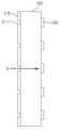
도 1은 본 발명의 일실시예에 따른 빔 컨트롤러를 구비한 어퍼쳐 혼 안테나의 분해 사시도이고, 도 2는 본 발명의 일실시예에 따른 빔 컨트롤러의 정면도와 배면도이고, 도 3은 도 1의 절단선 B-B'에 따른 빔 컨트롤러의 측 단면도이고, 도 4는 도 1의 절단선 A-A'에 따른 어퍼쳐 혼 안테나의 측단면도이다.1 is an exploded perspective view of an aperture horn antenna having a beam controller according to an embodiment of the present invention, FIG. 2 is a front view and a rear view of the beam controller according to an embodiment of the present invention, and FIG. Is a side cross-sectional view of the beam controller along cut line B-B ', and FIG. 4 is a side cross-sectional view of the aperture horn antenna along cut line A-A' in FIG.
이하에서는 도 1 내지 도 4를 참조하여 본 발명의 일실시예에 따른 어퍼쳐 혼 안테나(100) 및 빔 컨트롤러(200)를 상세히 설명하겠다.Hereinafter, the
도 1 내지 도 3을 참조하면, 본 발명의 일실시예에 따른 어퍼쳐 혼 안테나(100)는 도파관(110); 일단은 상기 도파관과 연결되고 타단에는 개구부(121)가 형성된 어퍼쳐 혼(120); 및 상기 개구부와 결합되며 복수의 슬릿(211)이 형성된 급전부(210)와, 상기 급전부와 결합된 유전체층(220)과, 상기 유전체층에 결합된 복수의 패치(230)를 구비하여 상기 급전부로 유입되어 상기 패치를 통하여 방사되는 신호의 빔 형상을 조절하는 빔 컨트롤러(200)를 포함한다.1 to 3, the
상기 빔 컨트롤러(200)는 어퍼쳐 혼의 형상이 피라미더 형인 경우에는 사각 형상의 다층기판으로 형성되고, 어퍼쳐 혼의 형상이 원형인 경우에는 원판 형상의 다층기판으로 형성된다.When the shape of the aperture horn is a pyramid type, the
상기 복수의 슬릿(211)은 금속재질의 판인 급전부(210) 상에서 다양한 길이(L)와 방사되는 신호의 전계 방향과 이루는 다양한 각도(θ)를 가지고 형성될 수 있다. 또한, 상기 복수의 슬릿(211)은 상기 급전부 상에서 모두 동일한 길이와 동일한 각도로 형성되는 것이 가능하며, 목적하는 빔의 형태에 따라 상기 길이와 상이한 각도를 가지고 형성될 수 있다.The plurality of
상기 빔 컨트롤러(200)는, 상기 슬릿의 길이(L) 및 상기 방사 신호의 전계방향(
도 2와 3을 참고하면, 상기 빔 컨트롤러(200)는 도파관(110)을 통하여 공급된 신호가 어퍼쳐 혼(120)에서 공간 급전된 후에 복수의 슬릿(211)을 통해 개별 급전되어 앞면에 형성된 복수의 패치(230)를 통해 목적하는 빔 형상으로 형성된다. 상기 어퍼쳐 혼 안테나(100)는 빔 컨트롤러(200)에 형성된 슬릿의 크기/개수 및 패치 사이즈를 변형시켜 각각의 소자의 크기/위상을 조절함으로써 배열 안테나 효과를 얻을 수 있다. 즉, 단일의 혼 안테나를 사용하는 경우에도 배열 안테나와 같이 빔 형상을 컨트롤할 수 있다.2 and 3, the
상기 빔 컨트롤러(200)는 유전체의 앞면 및 뒷면에 금속층을 형성한 후에 앞면에는 복수의 패치(230)를 형성하기 위하여 패치 부분만 제외하고 나머지 부분의 금속층 제거하며, 뒷면의 금속층에는 복수의 슬릿(211)에 해당하는 금속층 부분을 제거하여 상기 어퍼쳐 혼에서 공간 급전된 신호가 상기 복수의 슬릿을 통하여 개별 급전되도록 한다. 여기서, 상기 금속층을 제거하는 방법은 일반적으로 에칭으로 제거한다. 즉, 상기 슬릿은 기본적으로 신호는 금속으로 입사된 후에는 반사되지만 금속 틈으로는 유입되는 특성을 이용한 것이다. 상기 복수의 슬릿이 형성된 급전 부(210)와 복수의 패치 사이의 중간층인 유전체 층은 제거되지 않고 상기 슬릿으로 개별 급전된 신호가 최대한 낮은 손실률로 상기 복수의 패치를 통하여 방사되도록 한다.The
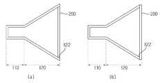
도 4를 참조하면, 상기 빔 컨트롤러(200)는 어퍼쳐 혼의 개구부(121)와 결합한다. 이 경우에, 도 4(a)에 도시된 바와 같이, 상기 어퍼쳐 혼의 개구부의 말단 내면(122)과 상기 빔 컨트롤러의 가장자리 측면이 접하도록 빔 컨트롤러(200)가 상기 어퍼쳐 혼의 개구부(121)에 삽입되어 결합될 수 있다. 또는, 도 4 (b)에 도시된 바와 같이, 상기 혼의 개구부(121)의 단면과 상기 급전부의 가장자리가 접하도록 결합되는 것도 가능하다. 전자의 결합 형태가 결합을 용이하게 하며, 이 경우에도 상기 개구부의 외면 말단에서 상기 빔 컨트롤러로 삽입되는 유전체 나사를 이용하여 양자를 결합시키는 것이 바람직하다.Referring to FIG. 4, the
상기 복수의 슬릿(211)은 상기 빔 컨트롤러의 가장자리에서 중심부를 향할수록 상응하는 패치를 통하여 방사되는 신호의 세기가 증가하도록 형성되는 것이 가능하다. 이 경우에 상기 복수의 슬릿(211)의 각각은 상기 빔 컨트롤러(200)의 가장자리에서 중심부를 향할수록 길이가 길게 형성되거나, 상기 복수의 슬릿의 각각은 상기 빔 컨트롤러의 가장자리에서 중심부를 향할수록 상기 전계 방향과 이루는 각도가 증가하도록 형성되는 것이 바람직하다.The plurality of
상기와 같은 슬릿의 형태 및 배치는 빔 컨트롤러의 중심부에서는 빔의 세기가 크고 가장자리 나머지 부분에서는 빔의 세기가 약해지는 경우, 즉 부엽 레벨이 작고 센터에 빔이 몰리면 빔폭이 좁아지는 현상이 발생하며, 좁은 빔폭을 요구하는 응용에 사용하는 것이 바람직하다. 뿐만 아니라 상기 슬릿의 길이 변화 및 상기 슬릿의 각도 변화에 따라 슬릿의 형태 및 배치를 적적하게 조절함으로써 상기와는 상이한 빔 형태를 얻을 수도 있다.The shape and arrangement of the slit is such that when the beam intensity is large at the center of the beam controller and the beam strength is weak at the rest of the edge, that is, when the side lobe level is small and the beam is concentrated at the center, the beam width becomes narrow. It is desirable to use for applications requiring a narrow beam width. In addition, the beam shape different from the above may be obtained by appropriately adjusting the shape and arrangement of the slit according to the change in the length of the slit and the change in the angle of the slit.
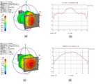
도 5(a)와 (b)는 종래의 어퍼쳐 혼 안테나 및 종래 혼 안테나의 빔 형상을 도시한 것이고, 도 5(c)와 (d)는 본 발명의 일실시예에 따른 빔 커트롤러를 구비한 어퍼쳐 혼 안테나 및 어퍼쳐 혼 안테나의 빔 형상을 도시한 것이다. 도 5(c)는 도 1의 어퍼쳐 혼 안테나에서 시각적인 편의성을 위하여 빔 컨트롤러가 제거된 상태를 도시하고 있다.5A and 5B illustrate beam shapes of a conventional aperture horn antenna and a conventional horn antenna, and FIGS. 5C and 5D illustrate a beam controller according to an embodiment of the present invention. The beam shape of the aperture horn antenna and the aperture horn antenna provided is shown. FIG. 5C illustrates a state in which the beam controller is removed for visual convenience in the aperture horn antenna of FIG. 1.
도 5를 참고하면, 종래의 어퍼쳐 혼 안테나는 개구부에서 방사되는 빔의 형상이 중심에서 작게 형성되어 있으나, 본 발명의 일실시예에 따른 어퍼쳐 혼 안테나는 슬릿의 방위각/고각 방향 개수 및 슬릿 사이즈를 변형할 수 있으므로 안테나를 여러 개 배치시키는 배열 안테나와 유사하거나 동일하게 목적하는 빔 형상을 얻도록 빔을 컨트롤할 수 있다. 따라서, 이와 같이 형성된 슬릿을 통하여 급전된 신호는 패치를 통하여 개구부의 중심부를 향하여 신호의 에너지를 집중시켜 목적하는 모양의 빔을 형성하게 된다.Referring to FIG. 5, the conventional aperture horn antenna has a small shape at the center of a beam radiated from an opening, but the aperture horn antenna according to an embodiment of the present invention has the number of slits and the azimuth / elevation direction of the slit. The size can be varied so that the beam can be controlled to achieve the desired beam shape, similarly or identical to an array antenna with multiple antennas. Therefore, the signal fed through the slit thus formed concentrates the energy of the signal toward the center of the opening through the patch to form a beam of a desired shape.
도 6은 본 발명의 일실시예에 따른 슬럿이 형성된 빔 컨트롤러의 배면도이고, 도 7은 빔 컨트롤러에 형성되는 다양한 길이와 기울기를 갖는 슬릿을 도시한 것이고, 도 8은 본 발명의 다른 실시예에 따른 슬럿이 형성된 빔 컨트롤러 의 배면도이다.FIG. 6 is a rear view of a beam controller in which a slot is formed according to an embodiment of the present invention, FIG. 7 illustrates slits having various lengths and inclinations formed in the beam controller, and FIG. 8 is another embodiment of the present invention. Is a rear view of the beam controller with slots formed according to.
상술한 바와 같이, 본 발명의 일실시예들 따른 빔 컨트롤러는 배면에 형성된 복수의 슬롯 기울기 및 슬롯 길이를 조절하여 상기 슬롯을 통해 나오는 신호의 세기를 결정하게 된다.As described above, the beam controller according to one embodiment of the present invention determines the strength of the signal coming out of the slot by adjusting the plurality of slot inclinations and slot lengths formed on the rear surface.
도 6을 참고하면, 본 발명의 다른 실시예에 따른 빔 컨트롤러(300)는 유전층(320)을 중심으로 배면에 급전부(310)에서 전계 방향(

상기 빔 컨트롤러는 배면에 형성된 복수의 슬릿을 통하여 급전되는 신호 크기를 상대적으로 차이가 나도록 하는 경우에는 복수의 슬릿의 각각의 길이와 전계 방향에θ 대한 기울기를 조절하면 된다.The beam controller may adjust the slope of each of the plurality of slits and the inclination with respect to the electric field direction when the signal magnitude fed through the plurality of slits formed on the rear surface is relatively different.
도 7 및 도 8을 참조하면, 사용자가 상기 어퍼쳐 혼의 개구부의 가장자리에서보다 중심에서 방사되는 신호의 크기가 크게 되도록 5개의 패치(430)와 이에 대응되는 5개의 슬릿(411)을 구비한 빔 컨트롤러(400)를 설계하는 경우에, 상기 패치(430) 통하여 방사되는 신호 크기 비율이 1:2:3:2:1 이 되도록 하는 것이 가능하다.7 and 8, a beam having five
우선, 도 7에 도시된 바와 같이, 상기 신호의 크기의 비가 1:2:3이 되도록 가장 자리로부터 중심으로 형성되는 슬릿(S)의 길이(L1, L2, L3)와 기울기(θ1,θ2, θ3)를 구한다. 상기 구해진 슬릿의 길이와 기울기를 이용하여 빔 컨트롤러(400)에 슬릿(411)과 패치(430)를 중심으로부터 좌우 대칭이 되도록 형성한다. 상기 빔 컨트롤러(400)는 방사되는 빔의 형상이 사용자가 의도하는 형상이 되도록 가장자리에서는 작은 에너지의 신호를 방상하고, 중심부에는 큰 에너지의 신호를 방사하게 된다.First, as shown in FIG. 7, the lengths L1, L2, L3 and the slopes θ1, θ2, θ3) is obtained. The
여기서, 상기 슬릿(S)의 길이는 L1 < L2 < L3이고, 상기 슬릿(S)의 기울기는 θ1 < θ2 < θ3이다.Here, the length of the slit S is L1 <L2 <L3, and the inclination of the slit S is θ1 <θ2 <θ3.
도 9는 본 발명의 실시예들에 따른 빔 컨트롤러와 결합가능한 어퍼쳐 혼 안테나 및 도파관 안테나의 예를 도시한 것이다.9 illustrates an example of an aperture horn antenna and a waveguide antenna that can be combined with a beam controller according to embodiments of the present invention.
도 9(a)는 종래의 피라미더형 혼 안테나와 사각판 형상의 빔 컨트롤러가 결합한 것이고, 도 9(b)는 종래의 원형 혼 안테나와 원판 형상의 빔 컨트롤러가 결합된 것이고, 도 9(c)는 종래의 도파관 안테나와 사각판 형상의 빔 컨트롤러가 결합된 것이다.FIG. 9 (a) shows a combination of a conventional pyramid-type horn antenna and a square plate-shaped beam controller, and FIG. 9 (b) shows a combination of a conventional circular horn antenna and a disk-shaped beam controller, and FIG. 9 (c). Is a combination of a conventional waveguide antenna and a square plate-shaped beam controller.
상기 빔 컨트롤러가 어퍼쳐 혼 안테나 또는 도파관 안테나의 개구부에 탈부탁되는 것이 가능하며, 이 경우에는 상기 개구부에 상기 빔 컨트롤러의 탈부착 수단을 구비하는 것이 바람직하다. 물론, 상기 빔 컨트롤러의 탈부착 수단은 상기 빔 컨트롤러에 형성되는 것도 가능하다.It is possible for the beam controller to be detached to an opening of an aperture horn antenna or a waveguide antenna, and in this case, it is preferable that the opening is provided with detachable means of the beam controller. Of course, the detachable means of the beam controller may be formed in the beam controller.
상술한 바와 같이, 본 발명의 실시예들에 따른 복수의 슬릿과 복수의 패치가 형성된 다층 기판 형태의 빔 컨트롤러를 구비한 어퍼쳐 혼 안테나는 단일의 안테나 에서도 방사되는 신호의 빔 형상을 형성시키는 것이 가능하다.As described above, an aperture horn antenna having a beam controller in the form of a multilayer substrate in which a plurality of slits and a plurality of patches are formed according to embodiments of the present invention forms a beam shape of a signal emitted from a single antenna. It is possible.
이상의 설명은 본 발명의 기술 사상을 예시적으로 설명한 것에 불과한 것으로서, 본 발명이 속하는 기술 분야에서 통상의 지식을 가진 자라면 본 발명의 본질적인 특성에서 벗어나지 않는 범위 내에서 다양한 수정, 변경 및 치환이 가능할 것이다. 따라서, 본 발명에 개시된 실시예 및 첨부된 도면들은 본 발명의 기술 사상을 한정하기 위한 것이 아니라 설명하기 위한 것이고, 이러한 실시예 및 첨부된 도면에 의하여 본 발명의 기술 사상의 범위가 한정되는 것은 아니다. 본 발명의 보호 범위는 아래의 청구범위에 의하여 해석되어야 하며, 그와 동등한 범위 내에 있는 모든 기술 사상은 본 발명의 권리범위에 포함되는 것으로 해석되어야 할 것이다.The above description is merely illustrative of the technical idea of the present invention, and various modifications, changes, and substitutions may be made by those skilled in the art without departing from the essential characteristics of the present invention. will be. Accordingly, the embodiments disclosed in the present invention and the accompanying drawings are not intended to limit the technical spirit of the present invention but to describe the present invention, and the scope of the technical idea of the present invention is not limited by the embodiments and the accompanying drawings. . The protection scope of the present invention should be interpreted by the following claims, and all technical ideas within the equivalent scope should be interpreted as being included in the scope of the present invention.
도 1은 본 발명의 일실시예에 따른 빔 컨트롤러를 구비한 어퍼쳐 혼 안테나의 분해 사시도이다.1 is an exploded perspective view of an aperture horn antenna having a beam controller according to an embodiment of the present invention.
도 2는 본 발명의 일실시예에 따른 빔 컨트롤러의 정면도와 배면도이다.2 is a front view and a rear view of a beam controller according to an embodiment of the present invention.
도 3은 도 1의 절단선 B-B'에 따른 빔 컨트롤러의 측 단면도이다.3 is a side cross-sectional view of the beam controller taken along the cutting line BB ′ of FIG. 1.
도 4는 도 1의 절단선 A-A'에 따른 어퍼쳐 혼 안테나의 측단면도이다.4 is a side cross-sectional view of the aperture horn antenna along the cutting line A-A 'of FIG.
도 5(a)와 (b) 및 (c)와 (d)의 각각은 종래의 어퍼쳐 혼 안테나의 빔 형상과, 본 발명의 일실시예에 따른 어퍼쳐 혼 안테나의 빔 형상의 비교도이다.5 (a), (b) and (c) and (d) are comparison diagrams of the beam shape of the conventional aperture horn antenna and the beam shape of the aperture horn antenna according to an embodiment of the present invention. .
도 6은 본 발명의 일실시예에 따른 슬럿이 형성된 빔 컨트롤러의 배면도이다.6 is a rear view of a beam controller in which a slot is formed according to an embodiment of the present invention.
도 7은 빔 컨트롤러에 형성되는 다양한 길이와 기울기를 갖는 슬릿을 도시한 것이다.7 illustrates slits having various lengths and inclinations formed in the beam controller.
도 8은 본 발명의 다른 실시예에 따른 슬럿이 형성된 빔 컨트롤러의 배면도이다.8 is a rear view of a beam controller in which a slot is formed according to another embodiment of the present invention.
도 9는 본 발명의 실시예들에 따른 빔 컨트롤러와 결합가능한 어퍼쳐 혼 안테나 및 도파관 안테나의 예를 도시한 것이다.9 illustrates an example of an aperture horn antenna and a waveguide antenna that can be combined with a beam controller according to embodiments of the present invention.
Claims (20)
Translated fromKoreanPriority Applications (3)
| Application Number | Priority Date | Filing Date | Title |
|---|---|---|---|
| KR1020090122627AKR100964990B1 (en) | 2009-12-10 | 2009-12-10 | Beam controller for apeture antenna, and apeture antenna therewith |
| US12/964,639US8686911B2 (en) | 2009-12-10 | 2010-12-09 | Beam controller for aperture antenna, and aperture antenna therewith |
| CN201010585263.5ACN102142613B (en) | 2009-12-10 | 2010-12-10 | Beam controller for aperture antenna, and aperture antenna therewith |
Applications Claiming Priority (1)
| Application Number | Priority Date | Filing Date | Title |
|---|---|---|---|
| KR1020090122627AKR100964990B1 (en) | 2009-12-10 | 2009-12-10 | Beam controller for apeture antenna, and apeture antenna therewith |
Publications (1)
| Publication Number | Publication Date |
|---|---|
| KR100964990B1true KR100964990B1 (en) | 2010-06-21 |
Family
ID=42370283
Family Applications (1)
| Application Number | Title | Priority Date | Filing Date |
|---|---|---|---|
| KR1020090122627AActiveKR100964990B1 (en) | 2009-12-10 | 2009-12-10 | Beam controller for apeture antenna, and apeture antenna therewith |
Country Status (3)
| Country | Link |
|---|---|
| US (1) | US8686911B2 (en) |
| KR (1) | KR100964990B1 (en) |
| CN (1) | CN102142613B (en) |
Cited By (2)
| Publication number | Priority date | Publication date | Assignee | Title |
|---|---|---|---|---|
| KR101707921B1 (en)* | 2016-06-30 | 2017-02-17 | 한국기초과학지원연구원 | Microwave heating and dryer using a rectangular waveguide traveling wave antenna |
| CN109541993A (en)* | 2018-10-28 | 2019-03-29 | 西南电子技术研究所(中国电子科技集团公司第十研究所) | Phase array antenna beam control device |
Families Citing this family (148)
| Publication number | Priority date | Publication date | Assignee | Title |
|---|---|---|---|---|
| CN102544717B (en)* | 2011-10-31 | 2014-06-04 | 深圳光启高等理工研究院 | Lens antenna based on metamaterial |
| US9113347B2 (en) | 2012-12-05 | 2015-08-18 | At&T Intellectual Property I, Lp | Backhaul link for distributed antenna system |
| US10009065B2 (en) | 2012-12-05 | 2018-06-26 | At&T Intellectual Property I, L.P. | Backhaul link for distributed antenna system |
| KR101405283B1 (en)* | 2013-02-20 | 2014-06-11 | 위월드 주식회사 | Planar horn array antenna |
| US9999038B2 (en) | 2013-05-31 | 2018-06-12 | At&T Intellectual Property I, L.P. | Remote distributed antenna system |
| US9525524B2 (en) | 2013-05-31 | 2016-12-20 | At&T Intellectual Property I, L.P. | Remote distributed antenna system |
| US8897697B1 (en) | 2013-11-06 | 2014-11-25 | At&T Intellectual Property I, Lp | Millimeter-wave surface-wave communications |
| US9692101B2 (en) | 2014-08-26 | 2017-06-27 | At&T Intellectual Property I, L.P. | Guided wave couplers for coupling electromagnetic waves between a waveguide surface and a surface of a wire |
| US9768833B2 (en) | 2014-09-15 | 2017-09-19 | At&T Intellectual Property I, L.P. | Method and apparatus for sensing a condition in a transmission medium of electromagnetic waves |
| US10063280B2 (en) | 2014-09-17 | 2018-08-28 | At&T Intellectual Property I, L.P. | Monitoring and mitigating conditions in a communication network |
| US9615269B2 (en) | 2014-10-02 | 2017-04-04 | At&T Intellectual Property I, L.P. | Method and apparatus that provides fault tolerance in a communication network |
| US9685992B2 (en) | 2014-10-03 | 2017-06-20 | At&T Intellectual Property I, L.P. | Circuit panel network and methods thereof |
| US9503189B2 (en) | 2014-10-10 | 2016-11-22 | At&T Intellectual Property I, L.P. | Method and apparatus for arranging communication sessions in a communication system |
| US9762289B2 (en) | 2014-10-14 | 2017-09-12 | At&T Intellectual Property I, L.P. | Method and apparatus for transmitting or receiving signals in a transportation system |
| US9973299B2 (en) | 2014-10-14 | 2018-05-15 | At&T Intellectual Property I, L.P. | Method and apparatus for adjusting a mode of communication in a communication network |
| US9577306B2 (en) | 2014-10-21 | 2017-02-21 | At&T Intellectual Property I, L.P. | Guided-wave transmission device and methods for use therewith |
| US9312919B1 (en) | 2014-10-21 | 2016-04-12 | At&T Intellectual Property I, Lp | Transmission device with impairment compensation and methods for use therewith |
| US9780834B2 (en) | 2014-10-21 | 2017-10-03 | At&T Intellectual Property I, L.P. | Method and apparatus for transmitting electromagnetic waves |
| US9627768B2 (en) | 2014-10-21 | 2017-04-18 | At&T Intellectual Property I, L.P. | Guided-wave transmission device with non-fundamental mode propagation and methods for use therewith |
| US9769020B2 (en) | 2014-10-21 | 2017-09-19 | At&T Intellectual Property I, L.P. | Method and apparatus for responding to events affecting communications in a communication network |
| US9520945B2 (en) | 2014-10-21 | 2016-12-13 | At&T Intellectual Property I, L.P. | Apparatus for providing communication services and methods thereof |
| US9653770B2 (en) | 2014-10-21 | 2017-05-16 | At&T Intellectual Property I, L.P. | Guided wave coupler, coupling module and methods for use therewith |
| US10340573B2 (en) | 2016-10-26 | 2019-07-02 | At&T Intellectual Property I, L.P. | Launcher with cylindrical coupling device and methods for use therewith |
| US9800327B2 (en) | 2014-11-20 | 2017-10-24 | At&T Intellectual Property I, L.P. | Apparatus for controlling operations of a communication device and methods thereof |
| US10009067B2 (en) | 2014-12-04 | 2018-06-26 | At&T Intellectual Property I, L.P. | Method and apparatus for configuring a communication interface |
| US9461706B1 (en) | 2015-07-31 | 2016-10-04 | At&T Intellectual Property I, Lp | Method and apparatus for exchanging communication signals |
| US9954287B2 (en) | 2014-11-20 | 2018-04-24 | At&T Intellectual Property I, L.P. | Apparatus for converting wireless signals and electromagnetic waves and methods thereof |
| US10243784B2 (en) | 2014-11-20 | 2019-03-26 | At&T Intellectual Property I, L.P. | System for generating topology information and methods thereof |
| US9997819B2 (en) | 2015-06-09 | 2018-06-12 | At&T Intellectual Property I, L.P. | Transmission medium and method for facilitating propagation of electromagnetic waves via a core |
| US9544006B2 (en) | 2014-11-20 | 2017-01-10 | At&T Intellectual Property I, L.P. | Transmission device with mode division multiplexing and methods for use therewith |
| US9742462B2 (en) | 2014-12-04 | 2017-08-22 | At&T Intellectual Property I, L.P. | Transmission medium and communication interfaces and methods for use therewith |
| US10144036B2 (en) | 2015-01-30 | 2018-12-04 | At&T Intellectual Property I, L.P. | Method and apparatus for mitigating interference affecting a propagation of electromagnetic waves guided by a transmission medium |
| US9876570B2 (en) | 2015-02-20 | 2018-01-23 | At&T Intellectual Property I, Lp | Guided-wave transmission device with non-fundamental mode propagation and methods for use therewith |
| US9749013B2 (en) | 2015-03-17 | 2017-08-29 | At&T Intellectual Property I, L.P. | Method and apparatus for reducing attenuation of electromagnetic waves guided by a transmission medium |
| US9705561B2 (en) | 2015-04-24 | 2017-07-11 | At&T Intellectual Property I, L.P. | Directional coupling device and methods for use therewith |
| US10224981B2 (en) | 2015-04-24 | 2019-03-05 | At&T Intellectual Property I, Lp | Passive electrical coupling device and methods for use therewith |
| US9948354B2 (en) | 2015-04-28 | 2018-04-17 | At&T Intellectual Property I, L.P. | Magnetic coupling device with reflective plate and methods for use therewith |
| US9793954B2 (en) | 2015-04-28 | 2017-10-17 | At&T Intellectual Property I, L.P. | Magnetic coupling device and methods for use therewith |
| US9490869B1 (en) | 2015-05-14 | 2016-11-08 | At&T Intellectual Property I, L.P. | Transmission medium having multiple cores and methods for use therewith |
| US9871282B2 (en) | 2015-05-14 | 2018-01-16 | At&T Intellectual Property I, L.P. | At least one transmission medium having a dielectric surface that is covered at least in part by a second dielectric |
| US9748626B2 (en) | 2015-05-14 | 2017-08-29 | At&T Intellectual Property I, L.P. | Plurality of cables having different cross-sectional shapes which are bundled together to form a transmission medium |
| US10650940B2 (en) | 2015-05-15 | 2020-05-12 | At&T Intellectual Property I, L.P. | Transmission medium having a conductive material and methods for use therewith |
| US9917341B2 (en) | 2015-05-27 | 2018-03-13 | At&T Intellectual Property I, L.P. | Apparatus and method for launching electromagnetic waves and for modifying radial dimensions of the propagating electromagnetic waves |
| US9912381B2 (en) | 2015-06-03 | 2018-03-06 | At&T Intellectual Property I, Lp | Network termination and methods for use therewith |
| US10103801B2 (en) | 2015-06-03 | 2018-10-16 | At&T Intellectual Property I, L.P. | Host node device and methods for use therewith |
| US9866309B2 (en) | 2015-06-03 | 2018-01-09 | At&T Intellectual Property I, Lp | Host node device and methods for use therewith |
| US10812174B2 (en) | 2015-06-03 | 2020-10-20 | At&T Intellectual Property I, L.P. | Client node device and methods for use therewith |
| US9913139B2 (en) | 2015-06-09 | 2018-03-06 | At&T Intellectual Property I, L.P. | Signal fingerprinting for authentication of communicating devices |
| US10142086B2 (en) | 2015-06-11 | 2018-11-27 | At&T Intellectual Property I, L.P. | Repeater and methods for use therewith |
| US9608692B2 (en) | 2015-06-11 | 2017-03-28 | At&T Intellectual Property I, L.P. | Repeater and methods for use therewith |
| US9820146B2 (en) | 2015-06-12 | 2017-11-14 | At&T Intellectual Property I, L.P. | Method and apparatus for authentication and identity management of communicating devices |
| US9667317B2 (en) | 2015-06-15 | 2017-05-30 | At&T Intellectual Property I, L.P. | Method and apparatus for providing security using network traffic adjustments |
| US9509415B1 (en) | 2015-06-25 | 2016-11-29 | At&T Intellectual Property I, L.P. | Methods and apparatus for inducing a fundamental wave mode on a transmission medium |
| US9640850B2 (en) | 2015-06-25 | 2017-05-02 | At&T Intellectual Property I, L.P. | Methods and apparatus for inducing a non-fundamental wave mode on a transmission medium |
| US9865911B2 (en) | 2015-06-25 | 2018-01-09 | At&T Intellectual Property I, L.P. | Waveguide system for slot radiating first electromagnetic waves that are combined into a non-fundamental wave mode second electromagnetic wave on a transmission medium |
| US10170840B2 (en) | 2015-07-14 | 2019-01-01 | At&T Intellectual Property I, L.P. | Apparatus and methods for sending or receiving electromagnetic signals |
| US9882257B2 (en) | 2015-07-14 | 2018-01-30 | At&T Intellectual Property I, L.P. | Method and apparatus for launching a wave mode that mitigates interference |
| US10205655B2 (en) | 2015-07-14 | 2019-02-12 | At&T Intellectual Property I, L.P. | Apparatus and methods for communicating utilizing an antenna array and multiple communication paths |
| US10044409B2 (en) | 2015-07-14 | 2018-08-07 | At&T Intellectual Property I, L.P. | Transmission medium and methods for use therewith |
| US10033107B2 (en) | 2015-07-14 | 2018-07-24 | At&T Intellectual Property I, L.P. | Method and apparatus for coupling an antenna to a device |
| US10341142B2 (en) | 2015-07-14 | 2019-07-02 | At&T Intellectual Property I, L.P. | Apparatus and methods for generating non-interfering electromagnetic waves on an uninsulated conductor |
| US9628116B2 (en) | 2015-07-14 | 2017-04-18 | At&T Intellectual Property I, L.P. | Apparatus and methods for transmitting wireless signals |
| US10148016B2 (en) | 2015-07-14 | 2018-12-04 | At&T Intellectual Property I, L.P. | Apparatus and methods for communicating utilizing an antenna array |
| US9722318B2 (en) | 2015-07-14 | 2017-08-01 | At&T Intellectual Property I, L.P. | Method and apparatus for coupling an antenna to a device |
| US10320586B2 (en) | 2015-07-14 | 2019-06-11 | At&T Intellectual Property I, L.P. | Apparatus and methods for generating non-interfering electromagnetic waves on an insulated transmission medium |
| US9853342B2 (en) | 2015-07-14 | 2017-12-26 | At&T Intellectual Property I, L.P. | Dielectric transmission medium connector and methods for use therewith |
| US10033108B2 (en) | 2015-07-14 | 2018-07-24 | At&T Intellectual Property I, L.P. | Apparatus and methods for generating an electromagnetic wave having a wave mode that mitigates interference |
| US9847566B2 (en) | 2015-07-14 | 2017-12-19 | At&T Intellectual Property I, L.P. | Method and apparatus for adjusting a field of a signal to mitigate interference |
| US10090606B2 (en) | 2015-07-15 | 2018-10-02 | At&T Intellectual Property I, L.P. | Antenna system with dielectric array and methods for use therewith |
| US9793951B2 (en) | 2015-07-15 | 2017-10-17 | At&T Intellectual Property I, L.P. | Method and apparatus for launching a wave mode that mitigates interference |
| US9608740B2 (en) | 2015-07-15 | 2017-03-28 | At&T Intellectual Property I, L.P. | Method and apparatus for launching a wave mode that mitigates interference |
| US9749053B2 (en) | 2015-07-23 | 2017-08-29 | At&T Intellectual Property I, L.P. | Node device, repeater and methods for use therewith |
| US9948333B2 (en) | 2015-07-23 | 2018-04-17 | At&T Intellectual Property I, L.P. | Method and apparatus for wireless communications to mitigate interference |
| US9871283B2 (en) | 2015-07-23 | 2018-01-16 | At&T Intellectual Property I, Lp | Transmission medium having a dielectric core comprised of plural members connected by a ball and socket configuration |
| US9912027B2 (en) | 2015-07-23 | 2018-03-06 | At&T Intellectual Property I, L.P. | Method and apparatus for exchanging communication signals |
| US9967173B2 (en) | 2015-07-31 | 2018-05-08 | At&T Intellectual Property I, L.P. | Method and apparatus for authentication and identity management of communicating devices |
| US9735833B2 (en) | 2015-07-31 | 2017-08-15 | At&T Intellectual Property I, L.P. | Method and apparatus for communications management in a neighborhood network |
| US9904535B2 (en) | 2015-09-14 | 2018-02-27 | At&T Intellectual Property I, L.P. | Method and apparatus for distributing software |
| US10079661B2 (en) | 2015-09-16 | 2018-09-18 | At&T Intellectual Property I, L.P. | Method and apparatus for use with a radio distributed antenna system having a clock reference |
| US10136434B2 (en) | 2015-09-16 | 2018-11-20 | At&T Intellectual Property I, L.P. | Method and apparatus for use with a radio distributed antenna system having an ultra-wideband control channel |
| US10009063B2 (en) | 2015-09-16 | 2018-06-26 | At&T Intellectual Property I, L.P. | Method and apparatus for use with a radio distributed antenna system having an out-of-band reference signal |
| US9769128B2 (en) | 2015-09-28 | 2017-09-19 | At&T Intellectual Property I, L.P. | Method and apparatus for encryption of communications over a network |
| US9729197B2 (en) | 2015-10-01 | 2017-08-08 | At&T Intellectual Property I, L.P. | Method and apparatus for communicating network management traffic over a network |
| US9876264B2 (en) | 2015-10-02 | 2018-01-23 | At&T Intellectual Property I, Lp | Communication system, guided wave switch and methods for use therewith |
| US10355367B2 (en) | 2015-10-16 | 2019-07-16 | At&T Intellectual Property I, L.P. | Antenna structure for exchanging wireless signals |
| US10665942B2 (en) | 2015-10-16 | 2020-05-26 | At&T Intellectual Property I, L.P. | Method and apparatus for adjusting wireless communications |
| US9912419B1 (en) | 2016-08-24 | 2018-03-06 | At&T Intellectual Property I, L.P. | Method and apparatus for managing a fault in a distributed antenna system |
| US9860075B1 (en) | 2016-08-26 | 2018-01-02 | At&T Intellectual Property I, L.P. | Method and communication node for broadband distribution |
| US10291311B2 (en) | 2016-09-09 | 2019-05-14 | At&T Intellectual Property I, L.P. | Method and apparatus for mitigating a fault in a distributed antenna system |
| US11032819B2 (en) | 2016-09-15 | 2021-06-08 | At&T Intellectual Property I, L.P. | Method and apparatus for use with a radio distributed antenna system having a control channel reference signal |
| US10340600B2 (en) | 2016-10-18 | 2019-07-02 | At&T Intellectual Property I, L.P. | Apparatus and methods for launching guided waves via plural waveguide systems |
| US10135147B2 (en) | 2016-10-18 | 2018-11-20 | At&T Intellectual Property I, L.P. | Apparatus and methods for launching guided waves via an antenna |
| US10135146B2 (en) | 2016-10-18 | 2018-11-20 | At&T Intellectual Property I, L.P. | Apparatus and methods for launching guided waves via circuits |
| US10811767B2 (en) | 2016-10-21 | 2020-10-20 | At&T Intellectual Property I, L.P. | System and dielectric antenna with convex dielectric radome |
| US10374316B2 (en) | 2016-10-21 | 2019-08-06 | At&T Intellectual Property I, L.P. | System and dielectric antenna with non-uniform dielectric |
| US9876605B1 (en) | 2016-10-21 | 2018-01-23 | At&T Intellectual Property I, L.P. | Launcher and coupling system to support desired guided wave mode |
| US9991580B2 (en) | 2016-10-21 | 2018-06-05 | At&T Intellectual Property I, L.P. | Launcher and coupling system for guided wave mode cancellation |
| US10312567B2 (en) | 2016-10-26 | 2019-06-04 | At&T Intellectual Property I, L.P. | Launcher with planar strip antenna and methods for use therewith |
| US10225025B2 (en) | 2016-11-03 | 2019-03-05 | At&T Intellectual Property I, L.P. | Method and apparatus for detecting a fault in a communication system |
| US10291334B2 (en) | 2016-11-03 | 2019-05-14 | At&T Intellectual Property I, L.P. | System for detecting a fault in a communication system |
| US10224634B2 (en) | 2016-11-03 | 2019-03-05 | At&T Intellectual Property I, L.P. | Methods and apparatus for adjusting an operational characteristic of an antenna |
| US10498044B2 (en) | 2016-11-03 | 2019-12-03 | At&T Intellectual Property I, L.P. | Apparatus for configuring a surface of an antenna |
| US10178445B2 (en) | 2016-11-23 | 2019-01-08 | At&T Intellectual Property I, L.P. | Methods, devices, and systems for load balancing between a plurality of waveguides |
| US10090594B2 (en) | 2016-11-23 | 2018-10-02 | At&T Intellectual Property I, L.P. | Antenna system having structural configurations for assembly |
| US10340603B2 (en) | 2016-11-23 | 2019-07-02 | At&T Intellectual Property I, L.P. | Antenna system having shielded structural configurations for assembly |
| US10535928B2 (en) | 2016-11-23 | 2020-01-14 | At&T Intellectual Property I, L.P. | Antenna system and methods for use therewith |
| US10340601B2 (en) | 2016-11-23 | 2019-07-02 | At&T Intellectual Property I, L.P. | Multi-antenna system and methods for use therewith |
| US10305190B2 (en) | 2016-12-01 | 2019-05-28 | At&T Intellectual Property I, L.P. | Reflecting dielectric antenna system and methods for use therewith |
| US10361489B2 (en) | 2016-12-01 | 2019-07-23 | At&T Intellectual Property I, L.P. | Dielectric dish antenna system and methods for use therewith |
| US10439675B2 (en) | 2016-12-06 | 2019-10-08 | At&T Intellectual Property I, L.P. | Method and apparatus for repeating guided wave communication signals |
| US10819035B2 (en) | 2016-12-06 | 2020-10-27 | At&T Intellectual Property I, L.P. | Launcher with helical antenna and methods for use therewith |
| US10020844B2 (en) | 2016-12-06 | 2018-07-10 | T&T Intellectual Property I, L.P. | Method and apparatus for broadcast communication via guided waves |
| US10135145B2 (en) | 2016-12-06 | 2018-11-20 | At&T Intellectual Property I, L.P. | Apparatus and methods for generating an electromagnetic wave along a transmission medium |
| US10727599B2 (en) | 2016-12-06 | 2020-07-28 | At&T Intellectual Property I, L.P. | Launcher with slot antenna and methods for use therewith |
| US10326494B2 (en) | 2016-12-06 | 2019-06-18 | At&T Intellectual Property I, L.P. | Apparatus for measurement de-embedding and methods for use therewith |
| US9927517B1 (en) | 2016-12-06 | 2018-03-27 | At&T Intellectual Property I, L.P. | Apparatus and methods for sensing rainfall |
| US10694379B2 (en) | 2016-12-06 | 2020-06-23 | At&T Intellectual Property I, L.P. | Waveguide system with device-based authentication and methods for use therewith |
| US10382976B2 (en) | 2016-12-06 | 2019-08-13 | At&T Intellectual Property I, L.P. | Method and apparatus for managing wireless communications based on communication paths and network device positions |
| US10637149B2 (en) | 2016-12-06 | 2020-04-28 | At&T Intellectual Property I, L.P. | Injection molded dielectric antenna and methods for use therewith |
| US10755542B2 (en) | 2016-12-06 | 2020-08-25 | At&T Intellectual Property I, L.P. | Method and apparatus for surveillance via guided wave communication |
| US10389029B2 (en) | 2016-12-07 | 2019-08-20 | At&T Intellectual Property I, L.P. | Multi-feed dielectric antenna system with core selection and methods for use therewith |
| US10359749B2 (en) | 2016-12-07 | 2019-07-23 | At&T Intellectual Property I, L.P. | Method and apparatus for utilities management via guided wave communication |
| US10168695B2 (en) | 2016-12-07 | 2019-01-01 | At&T Intellectual Property I, L.P. | Method and apparatus for controlling an unmanned aircraft |
| US10243270B2 (en) | 2016-12-07 | 2019-03-26 | At&T Intellectual Property I, L.P. | Beam adaptive multi-feed dielectric antenna system and methods for use therewith |
| US10139820B2 (en) | 2016-12-07 | 2018-11-27 | At&T Intellectual Property I, L.P. | Method and apparatus for deploying equipment of a communication system |
| US10027397B2 (en) | 2016-12-07 | 2018-07-17 | At&T Intellectual Property I, L.P. | Distributed antenna system and methods for use therewith |
| US9893795B1 (en) | 2016-12-07 | 2018-02-13 | At&T Intellectual Property I, Lp | Method and repeater for broadband distribution |
| US10547348B2 (en) | 2016-12-07 | 2020-01-28 | At&T Intellectual Property I, L.P. | Method and apparatus for switching transmission mediums in a communication system |
| US10446936B2 (en) | 2016-12-07 | 2019-10-15 | At&T Intellectual Property I, L.P. | Multi-feed dielectric antenna system and methods for use therewith |
| US9998870B1 (en) | 2016-12-08 | 2018-06-12 | At&T Intellectual Property I, L.P. | Method and apparatus for proximity sensing |
| US10069535B2 (en) | 2016-12-08 | 2018-09-04 | At&T Intellectual Property I, L.P. | Apparatus and methods for launching electromagnetic waves having a certain electric field structure |
| US10411356B2 (en) | 2016-12-08 | 2019-09-10 | At&T Intellectual Property I, L.P. | Apparatus and methods for selectively targeting communication devices with an antenna array |
| US10938108B2 (en) | 2016-12-08 | 2021-03-02 | At&T Intellectual Property I, L.P. | Frequency selective multi-feed dielectric antenna system and methods for use therewith |
| US10389037B2 (en) | 2016-12-08 | 2019-08-20 | At&T Intellectual Property I, L.P. | Apparatus and methods for selecting sections of an antenna array and use therewith |
| US9911020B1 (en) | 2016-12-08 | 2018-03-06 | At&T Intellectual Property I, L.P. | Method and apparatus for tracking via a radio frequency identification device |
| US10777873B2 (en) | 2016-12-08 | 2020-09-15 | At&T Intellectual Property I, L.P. | Method and apparatus for mounting network devices |
| US10530505B2 (en) | 2016-12-08 | 2020-01-07 | At&T Intellectual Property I, L.P. | Apparatus and methods for launching electromagnetic waves along a transmission medium |
| US10103422B2 (en) | 2016-12-08 | 2018-10-16 | At&T Intellectual Property I, L.P. | Method and apparatus for mounting network devices |
| US10601494B2 (en) | 2016-12-08 | 2020-03-24 | At&T Intellectual Property I, L.P. | Dual-band communication device and method for use therewith |
| US10326689B2 (en) | 2016-12-08 | 2019-06-18 | At&T Intellectual Property I, L.P. | Method and system for providing alternative communication paths |
| US10916969B2 (en) | 2016-12-08 | 2021-02-09 | At&T Intellectual Property I, L.P. | Method and apparatus for providing power using an inductive coupling |
| US9838896B1 (en) | 2016-12-09 | 2017-12-05 | At&T Intellectual Property I, L.P. | Method and apparatus for assessing network coverage |
| US10264586B2 (en) | 2016-12-09 | 2019-04-16 | At&T Mobility Ii Llc | Cloud-based packet controller and methods for use therewith |
| US10340983B2 (en) | 2016-12-09 | 2019-07-02 | At&T Intellectual Property I, L.P. | Method and apparatus for surveying remote sites via guided wave communications |
| US9973940B1 (en) | 2017-02-27 | 2018-05-15 | At&T Intellectual Property I, L.P. | Apparatus and methods for dynamic impedance matching of a guided wave launcher |
| US10298293B2 (en) | 2017-03-13 | 2019-05-21 | At&T Intellectual Property I, L.P. | Apparatus of communication utilizing wireless network devices |
| CN107275788B (en)* | 2017-07-03 | 2020-01-10 | 电子科技大学 | Millimeter wave fan-shaped beam cylindrical luneberg lens antenna based on metal perturbation structure |
| JP6981123B2 (en)* | 2017-09-14 | 2021-12-15 | 日本電気株式会社 | Antenna device |
Citations (3)
| Publication number | Priority date | Publication date | Assignee | Title |
|---|---|---|---|---|
| JPH01126803A (en)* | 1987-11-12 | 1989-05-18 | Mitsubishi Electric Corp | horn antenna device |
| US5515059A (en) | 1994-01-31 | 1996-05-07 | Northeastern University | Antenna array having two dimensional beam steering |
| JP2004320583A (en) | 2003-04-18 | 2004-11-11 | Japan Radio Co Ltd | Polarization switching antenna and radar device |
Family Cites Families (9)
| Publication number | Priority date | Publication date | Assignee | Title |
|---|---|---|---|---|
| US4364050A (en)* | 1981-02-09 | 1982-12-14 | Hazeltine Corporation | Microstrip antenna |
| US5258768A (en)* | 1990-07-26 | 1993-11-02 | Space Systems/Loral, Inc. | Dual band frequency reuse antenna |
| JPH09270633A (en)* | 1996-03-29 | 1997-10-14 | Hitachi Ltd | TEM slot array antenna |
| US6002305A (en)* | 1997-09-25 | 1999-12-14 | Endgate Corporation | Transition between circuit transmission line and microwave waveguide |
| WO2001020720A1 (en)* | 1999-09-14 | 2001-03-22 | Paratek Microwave, Inc. | Serially-fed phased array antennas with dielectric phase shifters |
| JP2004015408A (en)* | 2002-06-06 | 2004-01-15 | Oki Electric Ind Co Ltd | Slot array antenna |
| KR100624049B1 (en) | 2004-04-26 | 2006-09-20 | 주식회사 필셋 | Square Lattice Horn Array Antenna for Circularly Polarized Reception |
| JP4786939B2 (en)* | 2005-05-27 | 2011-10-05 | マスプロ電工株式会社 | Interference exclusion capability test equipment |
| US7629937B2 (en)* | 2008-02-25 | 2009-12-08 | Lockheed Martin Corporation | Horn antenna, waveguide or apparatus including low index dielectric material |
- 2009
- 2009-12-10KRKR1020090122627Apatent/KR100964990B1/enactiveActive
- 2010
- 2010-12-09USUS12/964,639patent/US8686911B2/enactiveActive
- 2010-12-10CNCN201010585263.5Apatent/CN102142613B/enactiveActive
Patent Citations (3)
| Publication number | Priority date | Publication date | Assignee | Title |
|---|---|---|---|---|
| JPH01126803A (en)* | 1987-11-12 | 1989-05-18 | Mitsubishi Electric Corp | horn antenna device |
| US5515059A (en) | 1994-01-31 | 1996-05-07 | Northeastern University | Antenna array having two dimensional beam steering |
| JP2004320583A (en) | 2003-04-18 | 2004-11-11 | Japan Radio Co Ltd | Polarization switching antenna and radar device |
Cited By (2)
| Publication number | Priority date | Publication date | Assignee | Title |
|---|---|---|---|---|
| KR101707921B1 (en)* | 2016-06-30 | 2017-02-17 | 한국기초과학지원연구원 | Microwave heating and dryer using a rectangular waveguide traveling wave antenna |
| CN109541993A (en)* | 2018-10-28 | 2019-03-29 | 西南电子技术研究所(中国电子科技集团公司第十研究所) | Phase array antenna beam control device |
Also Published As
| Publication number | Publication date |
|---|---|
| CN102142613B (en) | 2014-03-12 |
| US20110140980A1 (en) | 2011-06-16 |
| CN102142613A (en) | 2011-08-03 |
| US8686911B2 (en) | 2014-04-01 |
Similar Documents
| Publication | Publication Date | Title |
|---|---|---|
| KR100964990B1 (en) | Beam controller for apeture antenna, and apeture antenna therewith | |
| JP6400839B2 (en) | Omni antenna for mobile communication service | |
| CN109643852B (en) | End-fire circularly polarized substrate integrated waveguide horn antenna and manufacturing method thereof | |
| US9806419B2 (en) | Array antenna device | |
| KR20070077464A (en) | Circular Waveguide Antennas and Circular Waveguide Array Antennas | |
| EP3038206B1 (en) | Augmented e-plane taper techniques in variable inclination continuous transverse stub antenna arrays | |
| JP2005303986A (en) | Circular polarized array antenna | |
| US10141646B2 (en) | Array antenna device | |
| JP6195080B2 (en) | Antenna device | |
| CN106340711B (en) | Dual-polarized antenna | |
| JP6340690B2 (en) | Antenna device | |
| JP2015046846A (en) | Antenna device design method and antenna device | |
| AU620426B2 (en) | Slot array antenna | |
| EP2020699A1 (en) | Leaky wave antenna using waves propagating between parallel surfaces | |
| JP2001111335A (en) | Microstrip array antenna | |
| JP4524293B2 (en) | Circularly polarized grid array antenna | |
| EP1703590B1 (en) | Antenna array comprising at least two groups of at least one rod antenna | |
| JP4004674B2 (en) | Dielectric loaded antenna | |
| JP2007336459A (en) | Waveguide slot array antenna | |
| KR101593416B1 (en) | Antenna using a coupling element | |
| KR102120455B1 (en) | Automotive Radar Antenna with Wide Angle Characteristics | |
| JP5698394B2 (en) | Planar antenna | |
| KR102039398B1 (en) | Integrated Antenna Operating in Multiple Frequency Bands | |
| US12034210B2 (en) | Leaky wave antenna | |
| JP5873749B2 (en) | antenna |
Legal Events
| Date | Code | Title | Description |
|---|---|---|---|
| A201 | Request for examination | ||
| PA0109 | Patent application | Patent event code:PA01091R01D Comment text:Patent Application Patent event date:20091210 | |
| PA0201 | Request for examination | ||
| A302 | Request for accelerated examination | ||
| PA0302 | Request for accelerated examination | Patent event date:20100325 Patent event code:PA03022R01D Comment text:Request for Accelerated Examination Patent event date:20091210 Patent event code:PA03021R01I Comment text:Patent Application | |
| E701 | Decision to grant or registration of patent right | ||
| PE0701 | Decision of registration | Patent event code:PE07011S01D Comment text:Decision to Grant Registration Patent event date:20100607 | |
| GRNT | Written decision to grant | ||
| PR0701 | Registration of establishment | Comment text:Registration of Establishment Patent event date:20100611 Patent event code:PR07011E01D | |
| PR1002 | Payment of registration fee | Payment date:20100611 End annual number:3 Start annual number:1 | |
| PG1601 | Publication of registration | ||
| FPAY | Annual fee payment | Payment date:20130226 Year of fee payment:4 | |
| PR1001 | Payment of annual fee | Payment date:20130226 Start annual number:4 End annual number:4 | |
| FPAY | Annual fee payment | Payment date:20140414 Year of fee payment:5 | |
| PR1001 | Payment of annual fee | Payment date:20140414 Start annual number:5 End annual number:5 | |
| FPAY | Annual fee payment | Payment date:20150424 Year of fee payment:6 | |
| PR1001 | Payment of annual fee | Payment date:20150424 Start annual number:6 End annual number:6 | |
| FPAY | Annual fee payment | Payment date:20160511 Year of fee payment:7 | |
| PR1001 | Payment of annual fee | Payment date:20160511 Start annual number:7 End annual number:7 | |
| FPAY | Annual fee payment | Payment date:20190527 Year of fee payment:10 | |
| PR1001 | Payment of annual fee | Payment date:20190527 Start annual number:10 End annual number:10 | |
| PR1001 | Payment of annual fee | Payment date:20210504 Start annual number:12 End annual number:12 | |
| PR1001 | Payment of annual fee | Payment date:20230410 Start annual number:14 End annual number:14 | |
| PR1001 | Payment of annual fee | Payment date:20240417 Start annual number:15 End annual number:15 | |
| PR1001 | Payment of annual fee | Payment date:20250219 Start annual number:16 End annual number:16 |