KR100962552B1 - Camera System Providing Sound Source Information in the Photographed Image - Google Patents
Camera System Providing Sound Source Information in the Photographed ImageDownload PDFInfo
- Publication number
- KR100962552B1 KR100962552B1KR1020100005308AKR20100005308AKR100962552B1KR 100962552 B1KR100962552 B1KR 100962552B1KR 1020100005308 AKR1020100005308 AKR 1020100005308AKR 20100005308 AKR20100005308 AKR 20100005308AKR 100962552 B1KR100962552 B1KR 100962552B1
- Authority
- KR
- South Korea
- Prior art keywords
- sound source
- information
- camera
- image
- extracting
- Prior art date
- Legal status (The legal status is an assumption and is not a legal conclusion. Google has not performed a legal analysis and makes no representation as to the accuracy of the status listed.)
- Expired - Fee Related
Links
Images


Classifications
- G—PHYSICS
- G01—MEASURING; TESTING
- G01S—RADIO DIRECTION-FINDING; RADIO NAVIGATION; DETERMINING DISTANCE OR VELOCITY BY USE OF RADIO WAVES; LOCATING OR PRESENCE-DETECTING BY USE OF THE REFLECTION OR RERADIATION OF RADIO WAVES; ANALOGOUS ARRANGEMENTS USING OTHER WAVES
- G01S3/00—Direction-finders for determining the direction from which infrasonic, sonic, ultrasonic, or electromagnetic waves, or particle emission, not having a directional significance, are being received
- G01S3/80—Direction-finders for determining the direction from which infrasonic, sonic, ultrasonic, or electromagnetic waves, or particle emission, not having a directional significance, are being received using ultrasonic, sonic or infrasonic waves
- G01S3/802—Systems for determining direction or deviation from predetermined direction
- G01S3/808—Systems for determining direction or deviation from predetermined direction using transducers spaced apart and measuring phase or time difference between signals therefrom, i.e. path-difference systems
- G—PHYSICS
- G01—MEASURING; TESTING
- G01C—MEASURING DISTANCES, LEVELS OR BEARINGS; SURVEYING; NAVIGATION; GYROSCOPIC INSTRUMENTS; PHOTOGRAMMETRY OR VIDEOGRAMMETRY
- G01C21/00—Navigation; Navigational instruments not provided for in groups G01C1/00 - G01C19/00
- G01C21/26—Navigation; Navigational instruments not provided for in groups G01C1/00 - G01C19/00 specially adapted for navigation in a road network
- G01C21/34—Route searching; Route guidance
- G01C21/36—Input/output arrangements for on-board computers
- G01C21/3626—Details of the output of route guidance instructions
- G01C21/365—Guidance using head up displays or projectors, e.g. virtual vehicles or arrows projected on the windscreen or on the road itself
- G—PHYSICS
- G01—MEASURING; TESTING
- G01C—MEASURING DISTANCES, LEVELS OR BEARINGS; SURVEYING; NAVIGATION; GYROSCOPIC INSTRUMENTS; PHOTOGRAMMETRY OR VIDEOGRAMMETRY
- G01C21/00—Navigation; Navigational instruments not provided for in groups G01C1/00 - G01C19/00
- G01C21/26—Navigation; Navigational instruments not provided for in groups G01C1/00 - G01C19/00 specially adapted for navigation in a road network
- G01C21/34—Route searching; Route guidance
- G01C21/36—Input/output arrangements for on-board computers
- G01C21/3626—Details of the output of route guidance instructions
- G01C21/3635—Guidance using 3D or perspective road maps
- G—PHYSICS
- G01—MEASURING; TESTING
- G01C—MEASURING DISTANCES, LEVELS OR BEARINGS; SURVEYING; NAVIGATION; GYROSCOPIC INSTRUMENTS; PHOTOGRAMMETRY OR VIDEOGRAMMETRY
- G01C21/00—Navigation; Navigational instruments not provided for in groups G01C1/00 - G01C19/00
- G01C21/26—Navigation; Navigational instruments not provided for in groups G01C1/00 - G01C19/00 specially adapted for navigation in a road network
- G01C21/34—Route searching; Route guidance
- G01C21/36—Input/output arrangements for on-board computers
- G01C21/3667—Display of a road map
- G01C21/3673—Labelling using text of road map data items, e.g. road names, POI names
- H—ELECTRICITY
- H04—ELECTRIC COMMUNICATION TECHNIQUE
- H04N—PICTORIAL COMMUNICATION, e.g. TELEVISION
- H04N23/00—Cameras or camera modules comprising electronic image sensors; Control thereof
- H04N23/60—Control of cameras or camera modules
- H04N23/63—Control of cameras or camera modules by using electronic viewfinders
- H—ELECTRICITY
- H04—ELECTRIC COMMUNICATION TECHNIQUE
- H04N—PICTORIAL COMMUNICATION, e.g. TELEVISION
- H04N5/00—Details of television systems
- H04N5/222—Studio circuitry; Studio devices; Studio equipment
- H04N5/2224—Studio circuitry; Studio devices; Studio equipment related to virtual studio applications
- H04N5/2226—Determination of depth image, e.g. for foreground/background separation
Landscapes
- Engineering & Computer Science (AREA)
- Radar, Positioning & Navigation (AREA)
- Remote Sensing (AREA)
- Automation & Control Theory (AREA)
- Physics & Mathematics (AREA)
- General Physics & Mathematics (AREA)
- Multimedia (AREA)
- Signal Processing (AREA)
- Computer Vision & Pattern Recognition (AREA)
- Measurement Of Velocity Or Position Using Acoustic Or Ultrasonic Waves (AREA)
- Studio Devices (AREA)
Abstract
Translated fromKoreanDescription
Translated fromKorean본 발명은 소리를 찍는 카메라 시스템에 관한 것으로써, 더욱 상세하게는 소리센서와 이미지센서가 장착된 카메라 시스템에서 소리와 영상을 동시에 센싱하여 촬영된 영상에 음원 정보를 매핑하여 시각적으로 도시해 주는 카메라 시스템에 관한 것이다.The present invention relates to a camera system for taking a sound, and more particularly, a camera that visually shows sound and image by mapping sound source information to a captured image by simultaneously sensing a sound and an image in a camera system equipped with a sound sensor and an image sensor. It is about the system.
국방 분야에서 철책선 경계자는 전방으로 침투하는 침입자의 위치를 파악하거나 총기류의 발사 위치를 파악하거나 적 탱크 또는 헬기의 위치 및 이동방향을 파악하여, 신속히 대처하는 것이 중요하다. 특히 소리를 발생시키는 동물, 사람 및 물체가 건물이나 지형물에 의해서 은폐 및 엄폐되어 있을 경우, 단순한 소리의 위치만을 갖고 음원의 정확한 정보의 인지가 어렵기 때문에 이를 보다 용이하게 찾을 수 있도록 하는 것이 매우 중요하다.In the field of defense, it is important for rail guards to respond quickly by identifying the location of intruders penetrating forwards, the location of firearms, and the location and direction of enemy tanks or helicopters. In particular, when animals, people and objects that generate sound are concealed and covered by buildings or terrain, it is very difficult to find the exact information of the sound source with only a simple position of sound. It is important.
또한, 재난방지 및 테러방지 분야에서는 건물내의 저격수의 위치를 추적하는데 소리를 이용하는 경우가 많은데, 건물 내의 소리의 위치를 정확하게 추적하여 건물영상에 저격수의 위치를 도시함으로써 테러방지를 신속하게 처리할 수 있다.In addition, in the field of disaster prevention and terrorism, sound is often used to track the location of snipers in a building, and by accurately tracking the location of the sound in the building and showing the location of the sniper on the building image, the terrorism can be quickly processed. have.
또한, 음악용 방음실 제작 공정이나 자동차 방음 설계 공정이나 건물 위치 및 구조 설계 분야에서도 잡음이나 소음의 발생 위치를 파악하여, 관련 제작이나 설계에 반영하는 것도 매우 중요하다.In addition, it is also very important to grasp the location of noise and noise generation in the soundproofing room manufacturing process for music, soundproofing design process for automobiles, building location and structural design, and to reflect it in related production or design.
그런데, 종래기술에서는 음원의 위치나 방향, 종류 등의 음원 정보를 탐지하는 기술에 대해서는 다양한 개발이 이루어져 왔으나, 이렇게 탐지된 음원 정보를 사용자가 편리하게 이용할 수 있게 하는 기술은 아직 충분히 개발이 되어 있지 않은 실정이다.By the way, in the prior art, various techniques have been developed for detecting sound source information such as the position, direction, and type of the sound source, but the technology for making the user use the detected sound source information convenient has not been sufficiently developed. It is not true.
본 발명은 상기와 같은 점을 고려하여, 사용자가 촬영한 영상에 음원 정보를 표시하여 사용자가 편리하게 음원에 대한 정보를 습득하여 활용하게 하는, 촬영된 영상에 음원 정보를 표시하는 카메라 시스템을 제공한다.In view of the above, the present invention provides a camera system for displaying sound source information on a photographed image by displaying sound source information on an image captured by the user so that the user can conveniently acquire and use information about the sound source. do.
이상과 같은 기술적 과제를 달성하기 위하여, 본 발명에서는,In order to achieve the above technical problem, in this invention,
촬영된 영상에 음원 정보를 표시하는 카메라 시스템에 있어서,In the camera system for displaying sound source information in the captured image,
음원의 위치 및 방향을 추적하는 음원 센서(10); 음원 쪽의 영상을 촬영하는 카메라의 이미지 센서(30); 상기 카메라의 위치를 추출하는 GPS(20-1); 상기 카메라의 기준 좌표계를 추출하는 나침반(20-2); 상기 카메라의 뷰방향과 뷰각도를 추출하는 자이로 및 가속도 센서(20-3, 20-4); 상기 음원 센서(10)에서 출력되는 음원을 기반으로, 음원 정보를 추출하는 음원 정보 추출 모듈(300); 상기 이미지 센서(30)에서 출력되는 영상을 기반으로, 소실선 및 3차원 실마리를 추출하는 소실선 및 3차원 실마리 추출 모듈(310); 상기 GPS(20-1)과 나침반(20-2)에서 출력되는 정보를 기반으로, 카메라의 3차원 위치 및 기준 좌표계를 추출하는 카메라 위치 및 기준 좌표계 추출 모듈(320); 상기 자이로 및 가속도 센서(20-3, 20-4)에서 출력되는 정보를 기반으로, 카메라의 뷰 방향과 뷰 각도를 추출하는 카메라 뷰 방향 및 각도 추출 모듈(330); 상기 소실선 및 3차원 실마리 추출 모듈(310)과 카메라 위치 및 기준 좌표계 추출 모듈(320)과 카메라 뷰 방향 및 각도 추출 모듈(330)의 출력을 기반으로, 촬영된 영상에 있는 객체를 분리하고 이 객체의 3차원 위치 정보를 추출하는 객체 분리 및 3차원 정보 추출 모듈(350); 상기 음원 정보 추출 모듈(300)과 객체 분리 및 3차원 정보 추출 모듈(350)의 출력을 기반으로, 촬영된 영상에 음원을 매핑시키는 음원 및 영상 매핑 모듈(340); 음원 및 영상 매핑 모듈(340)의 출력을 기반으로, 촬영된 영상에 음원 정보 및 객체 정보를 화면에 표시하는 영상 및 정보 도시 모듈(360)을 포함하는 것을 특징으로 한다.A sound source sensor 10 for tracking the position and the direction of the sound source; An image sensor 30 of a camera for capturing an image of a sound source side; GPS (20-1) for extracting the position of the camera; A compass 20-2 for extracting a reference coordinate system of the camera; Gyro and acceleration sensors 20-3 and 20-4 for extracting the view direction and the view angle of the camera; A sound source information extraction module 300 for extracting sound source information based on a sound source output from the sound source sensor 10; A vanishing line and 3D clue extracting module 310 for extracting the vanishing line and the 3D clue based on the image output from the image sensor 30; A camera position and reference coordinate system extraction module 320 for extracting a three-dimensional position and a reference coordinate system of the camera based on the information output from the GPS 20-1 and the compass 20-2; A camera view direction and angle extraction module 330 for extracting a view direction and a view angle of the camera based on the information output from the gyro and the acceleration sensors 20-3 and 20-4; Based on the outputs of the vanishing line and the three-dimensional clue extraction module 310, the camera position and reference coordinate system extraction module 320, and the camera view direction and angle extraction module 330, the objects in the captured image are separated and separated. An object separation and three-dimensional information extraction module 350 for extracting three-dimensional position information of the object; A sound source and image mapping module 340 for mapping a sound source to a captured image based on the output of the sound source information extraction module 300 and the object separation and 3D information extraction module 350; Based on the output of the sound source and image mapping module 340, the image and information display module 360 for displaying the sound source information and object information on the screen, characterized in that it comprises a.
이상과 같은 본 발명을 사용하면, 사용자가 촬영한 영상에 음원 정보를 표시하여 사용자가 편리하게 음원에 대한 정보를 습득하여 활용하게 하는, 촬영된 영상에 음원 정보를 표시하는 카메라 시스템을 제공하는 것이 가능해진다.Using the present invention as described above, it is to provide a camera system for displaying the sound source information on the captured image to display the sound source information on the image taken by the user so that the user conveniently acquires and utilizes information about the sound source. It becomes possible.
특히 소리를 발생시키는 동물, 사람, 및 물체가 건물이나 지형물에 의해서 은폐되어 있을 경우, 본 발명의 방법 및 시스템을 사용하면 용이하게 음원에 대한 정보를 인지할 수 있다.In particular, when the animals, people, and objects that generate sound are concealed by buildings or terrain, the method and system of the present invention can easily recognize information about the sound source.
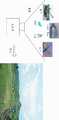
도1은 본 발명을 국방 분야에 적용한 사례를 도시함.
도2는 본 발명을 적용하여 표시되는 메인화면과 보조화면을 도시함.
도3은 본 발명의 전체적인 구성을 도시함.
도4는 본 발명에서 음원의 위치를 표시하는 방법을 도시함.
도5는 본 발명에서 객체 정보를 표시하는 방법을 도시함.
도6은 본 발명에서 음원과 영상 정보의 도시를 위한 정보처리 및 매핑과정을 도시함.
도7은 본 발명에서 기준 좌표계를 설정하는 방법을 도시함.Figure 1 shows an example of applying the present invention to the field of defense.
2 illustrates a main screen and a sub screen displayed by applying the present invention.
3 shows the overall configuration of the present invention.
Figure 4 shows a method for indicating the position of the sound source in the present invention.
5 illustrates a method of displaying object information in the present invention.
6 is a diagram illustrating an information processing and mapping process for illustrating sound sources and image information in the present invention.
7 shows a method of setting a reference coordinate system in the present invention.
도 1은 본 발명을 국방분야에 적용하여 전방에 위치하는 음원(탱크, 수류탄, 헬기, 동물, 간첩)들의 종류(탱크, 수류탄, 헬기, 동물, 간첩), 위치, 이동방향을 파악하는 것을 나타내는 도면이다.Figure 1 shows the application of the present invention to the defense sector to identify the types of sound sources (tanks, grenades, helicopters, animals, spies) (tanks, grenades, helicopters, animals, spies), position, and direction of movement located in the front Drawing.
카메라와 음원 추적장치가 일체화된 소리캠에서 전방의 영상을 촬영하고 전방에서 들려오는 각종 음향을 추적하여, 전방에 존재하는 음원의 위치를 도1의 우측 도면과 같이 촬영 영상에 매핑하여 표시하게 된다.In the sound cam integrated with the camera and the sound source tracking device, the front image is taken and the various sounds coming from the front are tracked, and the position of the sound source existing in front is mapped to the captured image as shown in the right figure of FIG. .
이때, 음원 추적은 공지의 다양한 음원추적 장치를 이용하게 되는데, 예를들면 2차원 또는 3차원 어레이 형태로 소리센서(예: 마이크)들이 배열된 음원 추적장치에서 각 마이크에 도달하는 소리의 위상차를 이용하여 음원의 3차원 위치를 파악한다.At this time, the sound source tracking uses various well-known sound source tracking devices, for example, the phase difference of the sound reaching each microphone in the sound source tracking device in which sound sensors (for example, microphones) are arranged in a two-dimensional or three-dimensional array form. Use it to identify the three-dimensional position of the sound source.
이렇게 음원을 추적하면, 음원의 개수, 3차원 위치가 파악되고, 도플러 효과를 이용하면 음원의 이동방향 및 이동속도가 파악되며, 각 음원의 스펙트럼을 분석하고 노이즈 제거하는 등 다양한 신호처리 기술을 이용하여 음원의 종류와 크기를 알 수 있게 된다. 여기서 음원의 소리 크기는 신호의 세기, 즉 진폭을 통해서 알 수 있다.When the sound source is tracked, the number and three-dimensional position of the sound source are identified, and when the Doppler effect is used, the direction and speed of movement of the sound source are determined, and various signal processing techniques are used, such as analyzing the spectrum of each sound source and removing noise. You can see the type and size of the sound source. Here, the loudness of the sound source can be known through the signal strength, that is, the amplitude.
다음으로, 이상과 같이 파악된 음원정보를 촬영된 영상에 표시하는 방법에 대해 도2를 참고로 하여 설명하기로 한다.Next, a method of displaying the sound source information identified as described above on the captured image will be described with reference to FIG. 2.
메인화면에는 카메라에서 촬영된 영상과 음원의 3차원 위치를 연동시켜 표시하고, 사용자가 메인화면에서 커서 등을 이용하여 특정 음원을 선택하면, 음원 관련 정보(예: 음원의 위치, 방향, 음원의 종류, 음원까지의 거리, 음원의 이동 방향, 음원의 이동속도 등)가 표시된다.The main screen displays the image captured by the camera and the 3D position of the sound source. If the user selects a specific sound source using the cursor, etc., the sound source related information (for example, the position, direction, and source of the sound source) is displayed. Type, distance to sound source, moving direction of sound source, moving speed of sound source, etc.) are displayed.
그리고, 보조화면에는 도2의 하단 왼쪽과 같이, 카메라의 현 위치와 뷰(view) 방향과 뷰(view) 앵글(각도)과 음원의 위치를 2차원적으로 표시되고, 도2의 하단 오른쪽과 같이 음원의 지도상의 위치가 2차원적으로 표시된다.On the sub-screen, as shown in the lower left of FIG. 2, the current position of the camera, the view direction, the view angle (angle), and the position of the sound source are displayed two-dimensionally. Likewise, the position on the map of the sound source is displayed two-dimensionally.
도2와 같이, 메인화면에는 촬영된 영상에, 음원 위치와, 선택된 음원 관련 정보를 표시하고, 보조화면에 카메라의 위치와 뷰 방향과 뷰 앵글과 함께 음원의 지도상의 위치를 표시하면, 사용자가 음원에 대한 다양한 정보를 인지할 수 있어서, 음원 관련 대응을 하기에 편리하게 된다.
As shown in Fig. 2, when the main screen displays the sound source position and the selected sound source related information on the captured image, and displays the position of the sound source along with the camera position, view direction, and view angle on the sub-screen, the user Various information about the sound source can be recognized, which makes it convenient to deal with the sound source.
다음으로 도2와 같이, 화면에 음원 관련 정보들을 표시하기 위한 본 발명의 전체적인 구성을 도3을 참고로 하여 설명하기로 한다.Next, as shown in Figure 2, the overall configuration of the present invention for displaying sound source-related information on the screen will be described with reference to FIG.
음원 추적 센서(10)는 음원의 위치와 방향을 추적하는 센서이고, 예를들면 어레이 형태로 배열된 마이크들인데 각 마이크로 입력되는 음원의 위상차를 이용하게 된다.The sound source tracking sensor 10 is a sensor for tracking the position and direction of the sound source, for example, microphones arranged in an array form to use the phase difference of the sound source input to each microphone.
이 음원 추적 센서(10)의 출력을 통해, 음원 위치 및 방향 추적 모듈(110)이 음원의 위치 및 방향을 추적하고, 음원 종류 추적 모듈(120)에 의해 각 음원의 스펙트럼을 분석하여 음원의 종류가 추적되며, 음원 이동 방향 추적 모듈(130)에 의해 도플러 효과를 이용하여 음원의 이동방향 및 이동속도가 파악되고, 음원의 소리 진폭에 따라서 음원의 소리 크기가 결정된다.Through the output of the sound source tracking sensor 10, the sound source position and direction tracking module 110 tracks the position and direction of the sound source, and analyzes the spectrum of each sound source by the sound source type tracking module 120 to determine the type of sound source. Is tracked, the moving direction and the moving speed of the sound source are grasped by the sound source moving direction tracking module 130, and the sound volume of the sound source is determined according to the sound amplitude of the sound source.
이때, 음원 인식 및 학습 모듈(140)은 실제 각 음원의 소리를 입력하여 스펙트럼 분석을 하여 각 음원별 스펙트럼을 본 발명의 장치에 인식시키고 학습시키는 모듈이다.
In this case, the sound source recognition and learning module 140 is a module that inputs the sound of each sound source and performs spectrum analysis to recognize and learn the spectrum of each sound source by the apparatus of the present invention.
다음으로, 위치 및 방향 파악 센서(20)는 카메라가 촬영한 위치 및 촬영 방향(뷰 방향)을 추적하기 위한 센서로서, 내부에 GPS 수신장치와 디지털 나침반, 자이로/가속도 센서가 존재하여, GPS수신장치에 의해 카메라의 3차원 위치를 추출하고, 카메라 3차원 위치 추적 모듈(150)에 의해 카메라의 3차원 위치가 추적되고, 디지털 나침반에 의해 카메라의 기준 좌표계가 설정되고 자이로/가속도 센서에 의해 회전량 측정되어 카메라 촬영 방향 추적 모듈(160)에 의해 카메라의 촬영방향이 추적된다.
Next, the position and direction sensor 20 is a sensor for tracking the position and the shooting direction (view direction) taken by the camera, there is a GPS receiver, a digital compass, gyro / acceleration sensor, GPS reception The device extracts the three-dimensional position of the camera, the three-dimensional position of the camera is tracked by the camera three-dimensional position tracking module 150, the reference coordinate system of the camera is set by the digital compass and rotated by the gyro / acceleration sensor. The total amount is measured and the shooting direction of the camera is tracked by the camera shooting direction tracking module 160.
마지막으로, 영상촬영 시스템(30)은 카메라를 의미하는 것이고, 디지털 카메라나 카메라 기능 포함 휴대폰 등을 이용하여, 전방 음원 쪽을 촬영하여 촬영된 영상이 영상 획득 및 저장 모듈(180)에 의해 수신되어 저장되게 된다.Lastly, the image capturing system 30 means a camera, and an image captured by photographing the front sound source using a digital camera or a mobile phone with a camera function is received by the image acquisition and storage module 180. Will be saved.
그리고, 음원 위치 및 영상 매핑 모듈(200)에 의해 도2의 상단의 메인화면과 같이 촬영된 영상에 음원들의 위치가 표시된다.Then, the positions of the sound sources are displayed on the image captured by the sound source position and the image mapping module 200 as shown in the main screen of FIG. 2.
이때, 음원이 카메라의 뷰 앵글 내에 존재하는 경우와 벗어나 경우를 구별하기 위해 도2의 메인 화면에서 도4에서와 같이 음원의 위치를 표시하는 것도 가능하다. 이렇게 표시하면, 음원이 카메라의 뷰 앵글을 벗어나서 도2의 메인 화면에서 음원의 위치가 표시되지 않는 가능성을 방지할 수 있다.At this time, it is possible to display the position of the sound source as shown in FIG. 4 on the main screen of FIG. In this way, it is possible to prevent the possibility that the sound source is out of the view angle of the camera so that the position of the sound source is not displayed on the main screen of FIG. 2.
도4와 같이 음원의 위치를 표시하면 사용자가 음원이 벗어난 것과 벗어난 방향을 인지하여 그 방향으로 다시 촬영을 하면 촬영된 영상에 음원의 위치가 정확하게 표시되게 된다.When the position of the sound source is displayed as shown in FIG. 4, when the user recognizes the direction of the sound source and the direction away from the sound source, and photographs again in that direction, the position of the sound source is accurately displayed on the captured image.
또한, 2D맵 데이터 연동 모듈(210)에 의해, 도2의 하단과 같이, 2차원적으로 카메라의 현 위치와 뷰 방향과 뷰 앵글, 음원의 위치가 2차원적으로 화면에 표시되고, 각 음원들의 2차원 지도상의 위치가 화면에 표시된다.In addition, the 2D map data interworking module 210 displays the current position of the camera, the view direction, the view angle, and the position of the sound source in two dimensions, as shown in the lower part of FIG. Their location on the two-dimensional map is displayed on the screen.
사용자 인터페이스(220)는 예를들면 도2의 메인화면에서 사용자가 특정 음원을 선택할 수 있게 하는 기능과 같은 각종 메뉴를 사용자가 선택하게 하고, 사용자가 카메라 촬영 및 저장을 실행하게 한다.
For example, the user interface 220 allows the user to select various menus such as a function for allowing the user to select a specific sound source on the main screen of FIG. 2, and allow the user to perform camera shooting and storage.
한편, 부가적인 기능으로서, 도2의 메인화면에서 각 음원 인근에 있는 각종 객체(물체)(건물, 시설물 등)에 대한 정보(도5의 건물의 종류, 위치, 거리 등)를 화면에 표시하는 기능이 유용한데, 이를 위하여 정보 도시 모듈(190)은 도5에서와 같이, 카메라 영상을 통해 촬영된 객체를 분리하여 인식하고 카메라의 위치 및 방향 정보를 통해 카메라의 위치와 방향을 추출하여 객체의 3차원 좌표를 추출하여, 수치 맵 데이터 DB에서 이 3차원 좌표에 대응하는 객체 정보를 탐색하여, 도5의 우측 상단 또는 하단과 같이 표시한다. 또한, 사용자가 특정 영상의 특정 위치를 선택하면, 이 위치에 있는 객체들의 상세정보(건물 종류, 위치, 거리 등)가 수치 맵 데이터DB에서 탐색되어 도5의 중간 부분의 풍선모양처럼 표시되게 된다.
Meanwhile, as an additional function, the main screen of FIG. 2 displays information (type, location, distance, etc. of the buildings of FIG. 5) about various objects (objects) (buildings, facilities, etc.) near each sound source on the screen. For this purpose, the information display module 190 separates and recognizes the object photographed through the camera image and extracts the position and direction of the camera through the camera position and orientation information as shown in FIG. 5. The three-dimensional coordinates are extracted, and object information corresponding to the three-dimensional coordinates is searched for in the numerical map data DB and displayed as shown in the upper right or lower part of FIG. In addition, when a user selects a specific location of a specific image, detailed information (building type, location, distance, etc.) of the objects at the location is searched in the numerical map data DB and displayed like a balloon in the middle of FIG. 5. .
다음으로, 본 발명의 핵심요소인 음원과 영상 정보의 도시를 위한 정보처리 및 매핑과정은 도6을 참고로 하여 설명하기로 한다.Next, the information processing and mapping process for illustrating the sound source and the image information, which are the core elements of the present invention, will be described with reference to FIG.
음원으로부터의 소리는 음원센서(10)에서 수집되어 음원 정보 추출 모듈(300)에 의해 분석되어서, 음원의 개수, 3차원 위치, 음원의 이동방향 및 이동속도, 음원의 종류와 크기와 같은 음원 정보가 파악된다.The sound from the sound source is collected by the sound source sensor 10 and analyzed by the sound source information extraction module 300, so that the sound source information such as the number of sound sources, three-dimensional position, the direction and speed of movement of the sound source, and the type and size of the sound source. Is grasped.
또한, 영상은 카메라의 이미지 센서(30)에서 촬영되어서, 소실선 및 3차원 실마리 추출 모듈(310)에서 공지의 다양한 영상처리 기술 및 인식 기술(예:Tour in Picture 기술)을 이용하여 촬영된 영상에서 소실선 및 3차원 실마리가 추출된다.In addition, the image is captured by the image sensor 30 of the camera, the vanishing line and the three-dimensional clue extraction module 310 by using a variety of known image processing techniques and recognition techniques (eg, Tour in Picture technology) The vanishing line and three-dimensional clues are extracted.
그리고, GPS(20-1)에서의 위치 정보와 나침반(20-2)에 의해, 카메라 위치 추출 및 기준 좌표계 추출 모듈(320)에서 카메라의 3차원상의 위치와 기준 좌표계가 설정된다.The camera position extraction and reference coordinate system extraction module 320 sets the three-dimensional position of the camera and the reference coordinate system by the position information and the compass 20-2 in the GPS 20-1.
또한, 자이로 센서(20-3)와 가속도 센서(20-4)에 의해, 카메라의 뷰 방향과 뷰 각도 추출 모듈(330)에서 카메라의 뷰 방향과 뷰 각도(앵글)가 추출된다.In addition, by the gyro sensor 20-3 and the acceleration sensor 20-4, the view direction and view angle (angle) of the camera are extracted by the view direction and view angle extraction module 330 of the camera.
이제, 소실선 및 3차원 실마리 추출 모듈(310)에 의해 추출된 소실선 및 3차원 실마리 정보와, 카메라 위치 추출 및 기준 좌표계 추출 모듈(320)에 의해 추출된 카메라의 3차원상의 위치와 기준 좌표계 정보와, 카메라의 뷰 방향과 뷰 각도추출 모듈(330)에 의해 추출된 카메라의 뷰 방향과 뷰 각도 정보는, 객체 분리 및 3차원 정보 추출 모듈(350)에 전달되어 공지의 다양한 객체 분리 및 3차원 위치 정보 추출 방법에 의해 객체들이 분리되고 이 분리된 객체들에 대한 3차원 위치 정보가 추출된다.Now, the vanishing line and the 3D clue information extracted by the vanishing line and the 3D clue extraction module 310 and the camera's three-dimensional position and the reference coordinate system extracted by the camera position extraction and reference coordinate system extraction module 320 The information and the view direction and view angle information of the camera extracted by the camera's view direction and view angle extraction module 330 are transmitted to the object separation and three-dimensional information extraction module 350 to separate various known objects. Objects are separated by the dimensional location information extraction method, and three-dimensional location information of the separated objects is extracted.
다음으로, 음원 정보 추출 모듈(300)에서 추출된 음원 정보(음원의 개수, 3차원 위치, 음원의 이동방향 및 이동속도, 음원의 종류와 크기 등)와, 객체 분리 및 3차원 정보 추출 모듈(350)에서 추출된 객체 정보(분리된 객체들의 3차원 위치 정보)가, 음원 및 영상 매핑 모듈(340)에 전달되어 매핑된다.Next, sound source information extracted from the sound source information extraction module 300 (number of sound sources, three-dimensional position, movement direction and speed of the sound source, type and size of the sound source), object separation and three-dimensional information extraction module ( The object information extracted from the 350 (3D position information of the separated objects) is transferred to the sound source and the image mapping module 340 and mapped.
마지막으로, 이렇게 매핑된 음원정보 및 객체 정보가 영상 및 정보 도시 모듈(360)에 전달되어, 도2에서와 같이 메인화면에 촬영된 영상과 함께 음원 정보가 표시되고, 보조화면에 현 위치와 뷰(view) 방향과 뷰(view) 앵글과 음원의 위치를 2차원적으로 표시되고, 음원의 지도상의 위치가 2차원적으로 표시되게 된다. 또한, 도5에서와 같이 도2의 메인화면에서 각 음원 인근에 있는 각종 객체에 대한 정보가 촬영된 화면 주변에 함께 표시되게 된다.
Finally, the mapped sound source information and object information are transferred to the image and information city module 360 so that the sound source information is displayed together with the image captured on the main screen as shown in FIG. The view direction, the view angle, and the position of the sound source are displayed two-dimensionally, and the position on the map of the sound source is displayed two-dimensionally. In addition, as shown in FIG. 5, information about various objects in the vicinity of each sound source is displayed together around the captured screen in the main screen of FIG. 2.
이제, 촬영된 카메라 영상에서 객체를 분리하고 객체의 거리 및 위치 등을 파악하는 방법에 대해 구체적으로 설명하기로 한다.Now, a method of separating an object from a photographed camera image and determining a distance and a position of the object will be described in detail.
촬영된 카메라 영상에서 객체를 분리하고 객체의 거리 및 위치 등을 파악하기 위해서는 카메라의 현재 위치, 카메라가 객체를 찍는 방향에 대한 정보가 사전에 제공되어야 하고, 이러한 정보를 획득하기 위해서 도7과 같이 기준좌표계가 먼저 설정되어야 한다.In order to separate the object from the photographed camera image and grasp the distance and position of the object, information about the current position of the camera and the direction in which the camera takes the object should be provided in advance, and as shown in FIG. The reference coordinate system must first be set.
도7를 참고하면, GPS 수신장치(20-1)를 통해서 카메라 위치를 획득하여 기준 좌표계의 원점에 매핑시키고, 디지털 나침반(20-2)을 사용하여 축좌표계의 방향을 동서남북 방향과 일치시키며, 카메라의 기학적구조를 기반으로 카메라의 촬영방향 등을 사전에 축 좌표계에 매핑하여 카메라의 기준좌표계를 설정한다.Referring to FIG. 7, the camera position is acquired through the GPS receiver 20-1 and mapped to the origin of the reference coordinate system, and the direction of the axis coordinate system is coincided with the north, east, south, and north directions using the digital compass 20-2. Based on the camera's mechanical structure, the camera's reference coordinate system is set by mapping the camera's shooting direction to the axis coordinate system in advance.
또한, 자이로 센서(20-3) 및 가속도 센서(20-4)를 통해서 카메라의 회전방향과 회전량을 측정하여, 실제 촬영시 카메라의 촬영방향(뷰 방향) 및 뷰 각도(view angle)를 계산한다.In addition, by measuring the rotation direction and the amount of rotation of the camera through the gyro sensor 20-3 and the acceleration sensor 20-4, to calculate the shooting direction (view direction) and view angle of the camera during actual shooting do.
상기의 카메라 시스템에 설정되어 있는 원점의 위치, 기준 좌표계, 뷰 방향, 뷰 앵글 등을 활용하여 촬영된 영상의 객체들에 대한 3차원 정보(3차원 위치 및 거리 정보)를 추출하게 된다.The 3D information (3D position and distance information) of the objects of the captured image is extracted by using the position of the origin, the reference coordinate system, the view direction, and the view angle set in the camera system.
촬영된 영상의 객체들에 대한 3차원 정보의 추출방법은 영상 내의 소실선, 3차원 실마리(원근감을 나타내는 각종 선 정보)등을 활용하여 객체를 분리하고 카메라로부터 거리를 계산하여 객체의 3차원 위치를 추출하게 된다. 이때 반드시 필요한 정보가 바로 상기의 카메라의 기준좌표계이다.
The method of extracting 3D information about the objects in the photographed image uses the vanishing line, 3D clue (various line information representing perspective), etc. to separate the object and calculate the distance from the camera to calculate the 3D position of the object. Will be extracted. At this time, the necessary information is the reference coordinate system of the camera.
이상에서는 본 발명의 바람직한 실시예를 설명하였으나, 본 발명은 이상의 실시예에 한정되는 것이 아니라, 본 발명의 원리를 벗어나지 않는 범위 내에서 다양한 변형 및 변경이 가능하다는 점에 유의해야 한다.
Although the preferred embodiments of the present invention have been described above, it should be noted that the present invention is not limited to the above embodiments, and various modifications and changes can be made without departing from the principles of the present invention.
Claims (11)
Translated fromKorean음원의 위치 및 방향을 추적하는 음원 센서(10);
음원 쪽의 영상을 촬영하는 카메라의 이미지 센서(30);
상기 카메라의 위치를 추출하는 GPS(20-1);
상기 카메라의 기준 좌표계를 추출하는 나침반(20-2);
상기 카메라의 뷰방향과 뷰각도를 추출하는 자이로 및 가속도 센서(20-3, 20-4);
상기 음원 센서(10)에서 출력되는 음원을 기반으로, 음원 정보를 추출하는 음원 정보 추출 모듈(300);
상기 이미지 센서(30)에서 출력되는 영상을 기반으로, 소실선 및 3차원 실마리를 추출하는 소실선 및 3차원 실마리 추출 모듈(310);
상기 GPS(20-1)과 나침반(20-2)에서 출력되는 정보를 기반으로, 카메라의 3차원 위치 및 기준 좌표계를 추출하는 카메라 위치 및 기준 좌표계 추출 모듈(320);
상기 자이로 및 가속도 센서(20-3, 20-4)에서 출력되는 정보를 기반으로, 카메라의 뷰 방향과 뷰 각도를 추출하는 카메라 뷰 방향 및 각도 추출 모듈(330);
상기 소실선 및 3차원 실마리 추출 모듈(310)과 카메라 위치 및 기준 좌표계 추출 모듈(320)과 카메라 뷰 방향 및 각도 추출 모듈(330)의 출력을 기반으로, 촬영된 영상에 있는 객체를 분리하고 이 객체의 3차원 위치 정보를 추출하는 객체 분리 및 3차원 정보 추출 모듈(350);
상기 음원 정보 추출 모듈(300)과 객체 분리 및 3차원 정보 추출 모듈(350)의 출력을 기반으로, 촬영된 영상의 객체에 음원을 매핑시키는 음원 및 영상 매핑 모듈(340);
음원 및 영상 매핑 모듈(340)의 출력을 기반으로, 촬영된 영상에 음원 정보 및 객체 정보를 화면에 표시하는 영상 및 정보 도시 모듈(360)을 포함하고,
상기 음원 정보는 음원의 위치 정보를 포함하고, 이 음원의 위치는 카메라 뷰 앵글 내에 존재하는 경우와 벗어난 경우를 구별하여 표시되는 것을 특징으로 하는, 촬영된 영상에 음원 정보를 표시하는 카메라 시스템.In the camera system for displaying sound source information in the captured image,
A sound source sensor 10 for tracking the position and the direction of the sound source;
An image sensor 30 of a camera for capturing an image of a sound source side;
GPS (20-1) for extracting the position of the camera;
A compass 20-2 for extracting a reference coordinate system of the camera;
Gyro and acceleration sensors 20-3 and 20-4 for extracting the view direction and the view angle of the camera;
A sound source information extraction module 300 for extracting sound source information based on a sound source output from the sound source sensor 10;
A vanishing line and 3D clue extracting module 310 for extracting the vanishing line and the 3D clue based on the image output from the image sensor 30;
A camera position and reference coordinate system extraction module 320 for extracting a three-dimensional position and a reference coordinate system of the camera based on the information output from the GPS 20-1 and the compass 20-2;
A camera view direction and angle extraction module 330 for extracting a view direction and a view angle of the camera based on the information output from the gyro and the acceleration sensors 20-3 and 20-4;
Based on the outputs of the vanishing line and the three-dimensional clue extraction module 310, the camera position and reference coordinate system extraction module 320, and the camera view direction and angle extraction module 330, the objects in the captured image are separated and separated. An object separation and three-dimensional information extraction module 350 for extracting three-dimensional position information of the object;
A sound source and image mapping module 340 for mapping a sound source to an object of a captured image based on the output of the sound source information extraction module 300 and the object separation and 3D information extraction module 350;
On the basis of the output of the sound source and the image mapping module 340, and includes an image and information showing module 360 for displaying the sound source information and object information on the screen,
And the sound source information includes position information of a sound source, and the position of the sound source is distinguished from the case where the sound source exists within the camera view angle and displayed when the sound source information is displayed.
상기 음원 센서(10)는, 어레이 형태로 배열된 마이크들 것을 특징으로 하는, 촬영된 영상에 음원 정보를 표시하는 카메라 시스템.The method of claim 1,
The sound source sensor (10), characterized in that the microphones arranged in an array, camera system for displaying the sound source information on the captured image.
상기 음원 센서(10)에 의해 파악된 각 음원의 스펙트럼을 분석하여 음원의 종류가 파악되는 것을 특징으로 하는, 촬영된 영상에 음원 정보를 표시하는 카메라 시스템.The method of claim 1,
Camera type for displaying the sound source information on the captured image, characterized in that the type of sound source is determined by analyzing the spectrum of each sound source identified by the sound source sensor (10).
도플러 효과를 이용하여 상기 음원 센서(10)부터 각 음원의 이동방향 및 이동속도가 파악되는 것을 특징으로 하는, 촬영된 영상에 음원 정보를 표시하는 카메라 시스템.The method of claim 1,
The camera system for displaying sound source information on the captured image, characterized in that the movement direction and the movement speed of each sound source from the sound source sensor (10) is grasped using the Doppler effect.
상기 음원 정보와 함께 카메라의 뷰 방향과 뷰 앵글이 2차원적으로 화면에 표시되는 것을 특징으로 하는, 촬영된 영상에 음원 정보를 표시하는 카메라 시스템.The method of claim 1,
And a view direction and a view angle of the camera are displayed on the screen in two dimensions together with the sound source information.
상기 음원 정보는 카메라와 음원들의 위치이고, 이들이 2차원 지도상에 표시되는 것을 특징으로 하는, 촬영된 영상에 음원 정보를 표시하는 카메라 시스템.The method of claim 1,
The sound source information is a camera and the position of the sound source, characterized in that they are displayed on a two-dimensional map, camera system for displaying the sound source information on the captured image.
상기 객체 정보는, 음원들 인근에 존재하는 객체들에 대한 영상 정보인 것을 특징으로 하는, 촬영된 영상에 음원 정보를 표시하는 카메라 시스템.The method of claim 1,
The object information is a camera system for displaying sound source information on the captured image, characterized in that the image information on the objects existing in the vicinity of the sound source.
상기 객체 정보는, 상기 객체와 관련된 문자 정보를 더 포함하는 것을 특징으로 하는, 촬영된 영상에 음원 정보를 표시하는 카메라 시스템.The method of claim 8,
The object information, the camera system for displaying sound source information on the captured image, characterized in that further comprises text information associated with the object.
음원 센서(10)에서 출력되는 음원을 기반으로, 음원 정보를 추출하는 음원 정보 추출 단계(300);
이미지 센서(30)에서 출력되는 영상을 기반으로, 소실선 및 3차원 실마리를 추출하는 소실선 및 3차원 실마리 추출 단계(310);
GPS(20-1)과 나침반(20-2)에서 출력되는 정보를 기반으로, 카메라의 3차원 위치 및 기준 좌표계를 추출하는 카메라 위치 및 기준 좌표계 추출 단계(320);
자이로 및 가속도 센서(20-3, 20-4)에서 출력되는 정보를 기반으로, 카메라의 뷰 방향과 뷰 각도를 추출하는 카메라 뷰 방향 및 각도 추출 단계(330)
상기 소실선 및 3차원 실마리 추출 단계(310)와 카메라 위치 및 기준 좌표계 추출 단계(320)와 카메라 뷰 방향 및 각도 추출 모듈(330)의 출력을 기반으로, 촬영된 영상에 있는 객체를 분리하고 이 객체의 3차원 위치 정보를 추출하는 객체 분리 및 3차원 정보 추출 단계(350);
상기 음원 정보 추출 단계(300)와 객체 분리 및 3차원 정보 추출 단계(350)의 출력을 기반으로, 촬영된 영상의 객체에 음원을 매핑시키는 음원 및 영상 매핑 단계(340);
음원 및 영상 매핑 단계(340)의 출력을 기반으로, 촬영된 영상에 음원 정보 및 객체 정보를 화면에 표시하는 영상 및 정보 도시 단계(360)를 포함하고,
상기 음원 정보는 음원의 위치 정보를 포함하고, 이 음원의 위치는 카메라 뷰 앵글 내에 존재하는 경우와 벗어난 경우를 구별하여 표시되는 것을 특징으로 하는, 촬영된 영상에 음원 정보를 표시하는 방법.
In the method for displaying the sound source information on the captured image,
A sound source information extraction step 300 of extracting sound source information based on a sound source output from the sound source sensor 10;
A vanishing line and three-dimensional clue extraction step 310 for extracting the vanishing line and the three-dimensional clue based on the image output from the image sensor 30;
A camera position and reference coordinate system extraction step 320 for extracting a three-dimensional position and a reference coordinate system of the camera based on the information output from the GPS 20-1 and the compass 20-2;
Based on the information output from the gyro and acceleration sensors 20-3 and 20-4, the camera view direction and angle extraction step 330 for extracting the view direction and view angle of the camera
Based on the vanishing line and the three-dimensional clue extraction step 310, the camera position and reference coordinate system extraction step 320, and the camera view direction and angle extraction module 330, the objects in the photographed image are separated and separated. An object separation and three-dimensional information extraction step 350 for extracting three-dimensional position information of the object;
A sound source and image mapping step 340 of mapping a sound source to an object of a captured image based on the output of the sound source information extraction step 300 and the object separation and three-dimensional information extraction step 350;
On the basis of the output of the sound source and image mapping step 340, the image and information showing step 360 for displaying the sound source information and object information on the screen image,
And the sound source information includes position information of a sound source, and the position of the sound source is distinguished from the case where the sound source is present within the camera view angle.
Priority Applications (1)
| Application Number | Priority Date | Filing Date | Title |
|---|---|---|---|
| KR1020100005308AKR100962552B1 (en) | 2010-01-20 | 2010-01-20 | Camera System Providing Sound Source Information in the Photographed Image |
Applications Claiming Priority (1)
| Application Number | Priority Date | Filing Date | Title |
|---|---|---|---|
| KR1020100005308AKR100962552B1 (en) | 2010-01-20 | 2010-01-20 | Camera System Providing Sound Source Information in the Photographed Image |
Publications (2)
| Publication Number | Publication Date |
|---|---|
| KR20100013347A KR20100013347A (en) | 2010-02-09 |
| KR100962552B1true KR100962552B1 (en) | 2010-06-11 |
Family
ID=42087341
Family Applications (1)
| Application Number | Title | Priority Date | Filing Date |
|---|---|---|---|
| KR1020100005308AExpired - Fee RelatedKR100962552B1 (en) | 2010-01-20 | 2010-01-20 | Camera System Providing Sound Source Information in the Photographed Image |
Country Status (1)
| Country | Link |
|---|---|
| KR (1) | KR100962552B1 (en) |
Cited By (1)
| Publication number | Priority date | Publication date | Assignee | Title |
|---|---|---|---|---|
| KR101285391B1 (en) | 2010-07-28 | 2013-07-10 | 주식회사 팬택 | Apparatus and method for merging acoustic object informations |
Families Citing this family (10)
| Publication number | Priority date | Publication date | Assignee | Title |
|---|---|---|---|---|
| KR20110095113A (en)* | 2010-02-16 | 2011-08-24 | 윤재민 | Sound Field Recognition Digital Video Recorder System and Its Operation Method |
| KR101155610B1 (en)* | 2010-04-30 | 2012-06-13 | 주식회사 에스원 | Apparatus for displaying sound source location and method thereof |
| JP6065370B2 (en)* | 2012-02-03 | 2017-01-25 | ソニー株式会社 | Information processing apparatus, information processing method, and program |
| KR101399881B1 (en)* | 2013-03-28 | 2014-05-27 | 현대제철 주식회사 | Apparatus for detecting air leakage in sinter process |
| US9736580B2 (en)* | 2015-03-19 | 2017-08-15 | Intel Corporation | Acoustic camera based audio visual scene analysis |
| JP6416032B2 (en)* | 2015-03-31 | 2018-10-31 | 株式会社熊谷組 | Diagnostic equipment |
| KR20170130041A (en)* | 2016-05-18 | 2017-11-28 | (주)에스엠인스트루먼트 | Acoustic Camera Display Method |
| KR102402457B1 (en) | 2017-09-15 | 2022-05-26 | 삼성전자 주식회사 | Method for processing contents and electronic device implementing the same |
| KR102061894B1 (en)* | 2017-12-04 | 2020-02-04 | 이진경 | Method and apparatus for identifying external audio signal |
| KR102227489B1 (en)* | 2019-07-10 | 2021-03-15 | 김영언 | Apparatus and method for visualizing sound source |
Citations (1)
| Publication number | Priority date | Publication date | Assignee | Title |
|---|---|---|---|---|
| KR100838239B1 (en)* | 2007-04-17 | 2008-06-17 | (주)에스엠인스트루먼트 | Computer-readable media recording sound quality display devices, sound quality display methods, and sound quality display programs |
- 2010
- 2010-01-20KRKR1020100005308Apatent/KR100962552B1/ennot_activeExpired - Fee Related
Patent Citations (1)
| Publication number | Priority date | Publication date | Assignee | Title |
|---|---|---|---|---|
| KR100838239B1 (en)* | 2007-04-17 | 2008-06-17 | (주)에스엠인스트루먼트 | Computer-readable media recording sound quality display devices, sound quality display methods, and sound quality display programs |
Cited By (1)
| Publication number | Priority date | Publication date | Assignee | Title |
|---|---|---|---|---|
| KR101285391B1 (en) | 2010-07-28 | 2013-07-10 | 주식회사 팬택 | Apparatus and method for merging acoustic object informations |
Also Published As
| Publication number | Publication date |
|---|---|
| KR20100013347A (en) | 2010-02-09 |
Similar Documents
| Publication | Publication Date | Title |
|---|---|---|
| KR100962552B1 (en) | Camera System Providing Sound Source Information in the Photographed Image | |
| US12270676B2 (en) | Navigation methods and apparatus for the visually impaired | |
| JP6763448B2 (en) | Visually enhanced navigation | |
| EP2915140B1 (en) | Fast initialization for monocular visual slam | |
| JP2019067383A5 (en) | ||
| KR101648339B1 (en) | Apparatus and method for providing service using a sensor and image recognition in portable terminal | |
| KR101330805B1 (en) | Apparatus and Method for Providing Augmented Reality | |
| KR20120002261A (en) | Apparatus and method for providing 3D augmented reality | |
| KR101665399B1 (en) | Object generation apparatus and method of based augmented reality using actual measured | |
| CN102446048B (en) | Information processing device and information processing method | |
| CN107402000A (en) | For the system and method relative to measuring instrument with reference to display device | |
| EP1887795A1 (en) | Metadata adding apparatus and metadata adding method | |
| KR100968837B1 (en) | Portable camera system provides information about captured objects | |
| CN110807361A (en) | Human body recognition method and device, computer equipment and storage medium | |
| JP2013250263A (en) | Object material recognition device and method of the same | |
| EP3047454A1 (en) | 3d reconstruction | |
| CN101936731A (en) | Device for acquiring 3D distance information and image | |
| US20130135446A1 (en) | Street view creating system and method thereof | |
| US20190026939A1 (en) | Systems and methods for blind and visually impaired person environment navigation assistance | |
| US9292963B2 (en) | Three-dimensional object model determination using a beacon | |
| JP2881193B1 (en) | Three-dimensional object recognition apparatus and method | |
| KR101432679B1 (en) | An apparatus and a method for recognizing material of the objects | |
| KR100550430B1 (en) | Driving guidance device and method of moving object using three-dimensional information | |
| CN103903253A (en) | Mobile terminal positioning method and system | |
| CN101204088A (en) | Metadata adding device and metadata adding method |
Legal Events
| Date | Code | Title | Description |
|---|---|---|---|
| A201 | Request for examination | ||
| PA0109 | Patent application | St.27 status event code:A-0-1-A10-A12-nap-PA0109 | |
| PA0201 | Request for examination | St.27 status event code:A-1-2-D10-D11-exm-PA0201 | |
| A302 | Request for accelerated examination | ||
| PA0302 | Request for accelerated examination | St.27 status event code:A-1-2-D10-D17-exm-PA0302 St.27 status event code:A-1-2-D10-D16-exm-PA0302 | |
| D13-X000 | Search requested | St.27 status event code:A-1-2-D10-D13-srh-X000 | |
| PG1501 | Laying open of application | St.27 status event code:A-1-1-Q10-Q12-nap-PG1501 | |
| D14-X000 | Search report completed | St.27 status event code:A-1-2-D10-D14-srh-X000 | |
| E902 | Notification of reason for refusal | ||
| PE0902 | Notice of grounds for rejection | St.27 status event code:A-1-2-D10-D21-exm-PE0902 | |
| E13-X000 | Pre-grant limitation requested | St.27 status event code:A-2-3-E10-E13-lim-X000 | |
| P11-X000 | Amendment of application requested | St.27 status event code:A-2-2-P10-P11-nap-X000 | |
| P13-X000 | Application amended | St.27 status event code:A-2-2-P10-P13-nap-X000 | |
| E701 | Decision to grant or registration of patent right | ||
| PE0701 | Decision of registration | St.27 status event code:A-1-2-D10-D22-exm-PE0701 | |
| GRNT | Written decision to grant | ||
| PR0701 | Registration of establishment | St.27 status event code:A-2-4-F10-F11-exm-PR0701 | |
| PR1002 | Payment of registration fee | St.27 status event code:A-2-2-U10-U11-oth-PR1002 Fee payment year number:1 | |
| PG1601 | Publication of registration | St.27 status event code:A-4-4-Q10-Q13-nap-PG1601 | |
| FPAY | Annual fee payment | Payment date:20130603 Year of fee payment:4 | |
| PR1001 | Payment of annual fee | St.27 status event code:A-4-4-U10-U11-oth-PR1001 Fee payment year number:4 | |
| FPAY | Annual fee payment | Payment date:20140523 Year of fee payment:5 | |
| PR1001 | Payment of annual fee | St.27 status event code:A-4-4-U10-U11-oth-PR1001 Fee payment year number:5 | |
| FPAY | Annual fee payment | Payment date:20150603 Year of fee payment:6 | |
| PR1001 | Payment of annual fee | St.27 status event code:A-4-4-U10-U11-oth-PR1001 Fee payment year number:6 | |
| PN2301 | Change of applicant | St.27 status event code:A-5-5-R10-R13-asn-PN2301 St.27 status event code:A-5-5-R10-R11-asn-PN2301 | |
| R18-X000 | Changes to party contact information recorded | St.27 status event code:A-5-5-R10-R18-oth-X000 | |
| FPAY | Annual fee payment | Payment date:20160525 Year of fee payment:7 | |
| PR1001 | Payment of annual fee | St.27 status event code:A-4-4-U10-U11-oth-PR1001 Fee payment year number:7 | |
| FPAY | Annual fee payment | Payment date:20170427 Year of fee payment:8 | |
| PR1001 | Payment of annual fee | St.27 status event code:A-4-4-U10-U11-oth-PR1001 Fee payment year number:8 | |
| P22-X000 | Classification modified | St.27 status event code:A-4-4-P10-P22-nap-X000 | |
| FPAY | Annual fee payment | Payment date:20180604 Year of fee payment:9 | |
| PR1001 | Payment of annual fee | St.27 status event code:A-4-4-U10-U11-oth-PR1001 Fee payment year number:9 | |
| FPAY | Annual fee payment | Payment date:20190603 Year of fee payment:10 | |
| PR1001 | Payment of annual fee | St.27 status event code:A-4-4-U10-U11-oth-PR1001 Fee payment year number:10 | |
| PR1001 | Payment of annual fee | St.27 status event code:A-4-4-U10-U11-oth-PR1001 Fee payment year number:11 | |
| PR1001 | Payment of annual fee | St.27 status event code:A-4-4-U10-U11-oth-PR1001 Fee payment year number:12 | |
| PC1903 | Unpaid annual fee | St.27 status event code:A-4-4-U10-U13-oth-PC1903 Not in force date:20220604 Payment event data comment text:Termination Category : DEFAULT_OF_REGISTRATION_FEE | |
| PC1903 | Unpaid annual fee | St.27 status event code:N-4-6-H10-H13-oth-PC1903 Ip right cessation event data comment text:Termination Category : DEFAULT_OF_REGISTRATION_FEE Not in force date:20220604 | |
| R18-X000 | Changes to party contact information recorded | St.27 status event code:A-5-5-R10-R18-oth-X000 |