KR100961020B1 - Cervical intervertebral prosthesis - Google Patents
Cervical intervertebral prosthesisDownload PDFInfo
- Publication number
- KR100961020B1 KR100961020B1KR1020047014210AKR20047014210AKR100961020B1KR 100961020 B1KR100961020 B1KR 100961020B1KR 1020047014210 AKR1020047014210 AKR 1020047014210AKR 20047014210 AKR20047014210 AKR 20047014210AKR 100961020 B1KR100961020 B1KR 100961020B1
- Authority
- KR
- South Korea
- Prior art keywords
- cervical intervertebral
- intervertebral prosthesis
- facing
- teeth
- vertebrae
- Prior art date
- Legal status (The legal status is an assumption and is not a legal conclusion. Google has not performed a legal analysis and makes no representation as to the accuracy of the status listed.)
- Expired - Lifetime
Links
- 239000011248coating agentSubstances0.000claimsdescription3
- 238000000576coating methodMethods0.000claimsdescription3
- 230000008468bone growthEffects0.000claimsdescription2
- 210000000988bone and boneAnatomy0.000abstractdescription14
- 210000002784stomachAnatomy0.000abstractdescription2
- 238000003780insertionMethods0.000description9
- 230000037431insertionEffects0.000description9
- 210000003238esophagusAnatomy0.000description7
- 230000007794irritationEffects0.000description6
- 210000002805bone matrixAnatomy0.000description4
- 238000006073displacement reactionMethods0.000description4
- 239000000463materialSubstances0.000description4
- 230000000694effectsEffects0.000description3
- 210000000056organAnatomy0.000description3
- 230000000295complement effectEffects0.000description2
- 210000005036nerveAnatomy0.000description2
- 239000000758substrateSubstances0.000description2
- 239000004698PolyethyleneSubstances0.000description1
- 210000001015abdomenAnatomy0.000description1
- 230000000975bioactive effectEffects0.000description1
- 210000004204blood vesselAnatomy0.000description1
- 238000010276constructionMethods0.000description1
- 230000012010growthEffects0.000description1
- 230000002452interceptive effectEffects0.000description1
- 210000004446longitudinal ligamentAnatomy0.000description1
- 239000002184metalSubstances0.000description1
- 230000010004neural pathwayEffects0.000description1
- 210000000118neural pathwayAnatomy0.000description1
- 239000004033plasticSubstances0.000description1
- 229920003023plasticPolymers0.000description1
- -1polyethylenePolymers0.000description1
- 229920000573polyethylenePolymers0.000description1
- 239000011148porous materialSubstances0.000description1
- 230000001737promoting effectEffects0.000description1
- 210000000278spinal cordAnatomy0.000description1
- 238000001356surgical procedureMethods0.000description1
Images


Classifications
- A—HUMAN NECESSITIES
- A61—MEDICAL OR VETERINARY SCIENCE; HYGIENE
- A61F—FILTERS IMPLANTABLE INTO BLOOD VESSELS; PROSTHESES; DEVICES PROVIDING PATENCY TO, OR PREVENTING COLLAPSING OF, TUBULAR STRUCTURES OF THE BODY, e.g. STENTS; ORTHOPAEDIC, NURSING OR CONTRACEPTIVE DEVICES; FOMENTATION; TREATMENT OR PROTECTION OF EYES OR EARS; BANDAGES, DRESSINGS OR ABSORBENT PADS; FIRST-AID KITS
- A61F2/00—Filters implantable into blood vessels; Prostheses, i.e. artificial substitutes or replacements for parts of the body; Appliances for connecting them with the body; Devices providing patency to, or preventing collapsing of, tubular structures of the body, e.g. stents
- A61F2/02—Prostheses implantable into the body
- A61F2/30—Joints
- A61F2/44—Joints for the spine, e.g. vertebrae, spinal discs
- A61F2/442—Intervertebral or spinal discs, e.g. resilient
- A61F2/4425—Intervertebral or spinal discs, e.g. resilient made of articulated components
- A—HUMAN NECESSITIES
- A61—MEDICAL OR VETERINARY SCIENCE; HYGIENE
- A61F—FILTERS IMPLANTABLE INTO BLOOD VESSELS; PROSTHESES; DEVICES PROVIDING PATENCY TO, OR PREVENTING COLLAPSING OF, TUBULAR STRUCTURES OF THE BODY, e.g. STENTS; ORTHOPAEDIC, NURSING OR CONTRACEPTIVE DEVICES; FOMENTATION; TREATMENT OR PROTECTION OF EYES OR EARS; BANDAGES, DRESSINGS OR ABSORBENT PADS; FIRST-AID KITS
- A61F2/00—Filters implantable into blood vessels; Prostheses, i.e. artificial substitutes or replacements for parts of the body; Appliances for connecting them with the body; Devices providing patency to, or preventing collapsing of, tubular structures of the body, e.g. stents
- A61F2/02—Prostheses implantable into the body
- A61F2/30—Joints
- A61F2/44—Joints for the spine, e.g. vertebrae, spinal discs
- A—HUMAN NECESSITIES
- A61—MEDICAL OR VETERINARY SCIENCE; HYGIENE
- A61F—FILTERS IMPLANTABLE INTO BLOOD VESSELS; PROSTHESES; DEVICES PROVIDING PATENCY TO, OR PREVENTING COLLAPSING OF, TUBULAR STRUCTURES OF THE BODY, e.g. STENTS; ORTHOPAEDIC, NURSING OR CONTRACEPTIVE DEVICES; FOMENTATION; TREATMENT OR PROTECTION OF EYES OR EARS; BANDAGES, DRESSINGS OR ABSORBENT PADS; FIRST-AID KITS
- A61F2/00—Filters implantable into blood vessels; Prostheses, i.e. artificial substitutes or replacements for parts of the body; Appliances for connecting them with the body; Devices providing patency to, or preventing collapsing of, tubular structures of the body, e.g. stents
- A61F2/02—Prostheses implantable into the body
- A61F2/30—Joints
- A61F2/30767—Special external or bone-contacting surface, e.g. coating for improving bone ingrowth
- A—HUMAN NECESSITIES
- A61—MEDICAL OR VETERINARY SCIENCE; HYGIENE
- A61F—FILTERS IMPLANTABLE INTO BLOOD VESSELS; PROSTHESES; DEVICES PROVIDING PATENCY TO, OR PREVENTING COLLAPSING OF, TUBULAR STRUCTURES OF THE BODY, e.g. STENTS; ORTHOPAEDIC, NURSING OR CONTRACEPTIVE DEVICES; FOMENTATION; TREATMENT OR PROTECTION OF EYES OR EARS; BANDAGES, DRESSINGS OR ABSORBENT PADS; FIRST-AID KITS
- A61F2/00—Filters implantable into blood vessels; Prostheses, i.e. artificial substitutes or replacements for parts of the body; Appliances for connecting them with the body; Devices providing patency to, or preventing collapsing of, tubular structures of the body, e.g. stents
- A61F2/02—Prostheses implantable into the body
- A61F2/30—Joints
- A61F2002/30001—Additional features of subject-matter classified in A61F2/28, A61F2/30 and subgroups thereof
- A61F2002/30316—The prosthesis having different structural features at different locations within the same prosthesis; Connections between prosthetic parts; Special structural features of bone or joint prostheses not otherwise provided for
- A61F2002/30329—Connections or couplings between prosthetic parts, e.g. between modular parts; Connecting elements
- A61F2002/30383—Connections or couplings between prosthetic parts, e.g. between modular parts; Connecting elements made by laterally inserting a protrusion, e.g. a rib into a complementarily-shaped groove
- A—HUMAN NECESSITIES
- A61—MEDICAL OR VETERINARY SCIENCE; HYGIENE
- A61F—FILTERS IMPLANTABLE INTO BLOOD VESSELS; PROSTHESES; DEVICES PROVIDING PATENCY TO, OR PREVENTING COLLAPSING OF, TUBULAR STRUCTURES OF THE BODY, e.g. STENTS; ORTHOPAEDIC, NURSING OR CONTRACEPTIVE DEVICES; FOMENTATION; TREATMENT OR PROTECTION OF EYES OR EARS; BANDAGES, DRESSINGS OR ABSORBENT PADS; FIRST-AID KITS
- A61F2/00—Filters implantable into blood vessels; Prostheses, i.e. artificial substitutes or replacements for parts of the body; Appliances for connecting them with the body; Devices providing patency to, or preventing collapsing of, tubular structures of the body, e.g. stents
- A61F2/02—Prostheses implantable into the body
- A61F2/30—Joints
- A61F2002/30001—Additional features of subject-matter classified in A61F2/28, A61F2/30 and subgroups thereof
- A61F2002/30316—The prosthesis having different structural features at different locations within the same prosthesis; Connections between prosthetic parts; Special structural features of bone or joint prostheses not otherwise provided for
- A61F2002/30329—Connections or couplings between prosthetic parts, e.g. between modular parts; Connecting elements
- A61F2002/30476—Connections or couplings between prosthetic parts, e.g. between modular parts; Connecting elements locked by an additional locking mechanism
- A—HUMAN NECESSITIES
- A61—MEDICAL OR VETERINARY SCIENCE; HYGIENE
- A61F—FILTERS IMPLANTABLE INTO BLOOD VESSELS; PROSTHESES; DEVICES PROVIDING PATENCY TO, OR PREVENTING COLLAPSING OF, TUBULAR STRUCTURES OF THE BODY, e.g. STENTS; ORTHOPAEDIC, NURSING OR CONTRACEPTIVE DEVICES; FOMENTATION; TREATMENT OR PROTECTION OF EYES OR EARS; BANDAGES, DRESSINGS OR ABSORBENT PADS; FIRST-AID KITS
- A61F2/00—Filters implantable into blood vessels; Prostheses, i.e. artificial substitutes or replacements for parts of the body; Appliances for connecting them with the body; Devices providing patency to, or preventing collapsing of, tubular structures of the body, e.g. stents
- A61F2/02—Prostheses implantable into the body
- A61F2/30—Joints
- A61F2002/30001—Additional features of subject-matter classified in A61F2/28, A61F2/30 and subgroups thereof
- A61F2002/30316—The prosthesis having different structural features at different locations within the same prosthesis; Connections between prosthetic parts; Special structural features of bone or joint prostheses not otherwise provided for
- A61F2002/30535—Special structural features of bone or joint prostheses not otherwise provided for
- A61F2002/30576—Special structural features of bone or joint prostheses not otherwise provided for with extending fixation tabs
- A61F2002/30578—Special structural features of bone or joint prostheses not otherwise provided for with extending fixation tabs having apertures, e.g. for receiving fixation screws
- A—HUMAN NECESSITIES
- A61—MEDICAL OR VETERINARY SCIENCE; HYGIENE
- A61F—FILTERS IMPLANTABLE INTO BLOOD VESSELS; PROSTHESES; DEVICES PROVIDING PATENCY TO, OR PREVENTING COLLAPSING OF, TUBULAR STRUCTURES OF THE BODY, e.g. STENTS; ORTHOPAEDIC, NURSING OR CONTRACEPTIVE DEVICES; FOMENTATION; TREATMENT OR PROTECTION OF EYES OR EARS; BANDAGES, DRESSINGS OR ABSORBENT PADS; FIRST-AID KITS
- A61F2/00—Filters implantable into blood vessels; Prostheses, i.e. artificial substitutes or replacements for parts of the body; Appliances for connecting them with the body; Devices providing patency to, or preventing collapsing of, tubular structures of the body, e.g. stents
- A61F2/02—Prostheses implantable into the body
- A61F2/30—Joints
- A61F2002/30001—Additional features of subject-matter classified in A61F2/28, A61F2/30 and subgroups thereof
- A61F2002/30621—Features concerning the anatomical functioning or articulation of the prosthetic joint
- A61F2002/30649—Ball-and-socket joints
- A61F2002/3065—Details of the ball-shaped head
- A—HUMAN NECESSITIES
- A61—MEDICAL OR VETERINARY SCIENCE; HYGIENE
- A61F—FILTERS IMPLANTABLE INTO BLOOD VESSELS; PROSTHESES; DEVICES PROVIDING PATENCY TO, OR PREVENTING COLLAPSING OF, TUBULAR STRUCTURES OF THE BODY, e.g. STENTS; ORTHOPAEDIC, NURSING OR CONTRACEPTIVE DEVICES; FOMENTATION; TREATMENT OR PROTECTION OF EYES OR EARS; BANDAGES, DRESSINGS OR ABSORBENT PADS; FIRST-AID KITS
- A61F2/00—Filters implantable into blood vessels; Prostheses, i.e. artificial substitutes or replacements for parts of the body; Appliances for connecting them with the body; Devices providing patency to, or preventing collapsing of, tubular structures of the body, e.g. stents
- A61F2/02—Prostheses implantable into the body
- A61F2/30—Joints
- A61F2/30767—Special external or bone-contacting surface, e.g. coating for improving bone ingrowth
- A61F2/30771—Special external or bone-contacting surface, e.g. coating for improving bone ingrowth applied in original prostheses, e.g. holes or grooves
- A61F2002/3082—Grooves
- A—HUMAN NECESSITIES
- A61—MEDICAL OR VETERINARY SCIENCE; HYGIENE
- A61F—FILTERS IMPLANTABLE INTO BLOOD VESSELS; PROSTHESES; DEVICES PROVIDING PATENCY TO, OR PREVENTING COLLAPSING OF, TUBULAR STRUCTURES OF THE BODY, e.g. STENTS; ORTHOPAEDIC, NURSING OR CONTRACEPTIVE DEVICES; FOMENTATION; TREATMENT OR PROTECTION OF EYES OR EARS; BANDAGES, DRESSINGS OR ABSORBENT PADS; FIRST-AID KITS
- A61F2/00—Filters implantable into blood vessels; Prostheses, i.e. artificial substitutes or replacements for parts of the body; Appliances for connecting them with the body; Devices providing patency to, or preventing collapsing of, tubular structures of the body, e.g. stents
- A61F2/02—Prostheses implantable into the body
- A61F2/30—Joints
- A61F2/30767—Special external or bone-contacting surface, e.g. coating for improving bone ingrowth
- A61F2/30771—Special external or bone-contacting surface, e.g. coating for improving bone ingrowth applied in original prostheses, e.g. holes or grooves
- A61F2002/30841—Sharp anchoring protrusions for impaction into the bone, e.g. sharp pins, spikes
- A61F2002/30845—Sharp anchoring protrusions for impaction into the bone, e.g. sharp pins, spikes with cutting edges
- A—HUMAN NECESSITIES
- A61—MEDICAL OR VETERINARY SCIENCE; HYGIENE
- A61F—FILTERS IMPLANTABLE INTO BLOOD VESSELS; PROSTHESES; DEVICES PROVIDING PATENCY TO, OR PREVENTING COLLAPSING OF, TUBULAR STRUCTURES OF THE BODY, e.g. STENTS; ORTHOPAEDIC, NURSING OR CONTRACEPTIVE DEVICES; FOMENTATION; TREATMENT OR PROTECTION OF EYES OR EARS; BANDAGES, DRESSINGS OR ABSORBENT PADS; FIRST-AID KITS
- A61F2/00—Filters implantable into blood vessels; Prostheses, i.e. artificial substitutes or replacements for parts of the body; Appliances for connecting them with the body; Devices providing patency to, or preventing collapsing of, tubular structures of the body, e.g. stents
- A61F2/02—Prostheses implantable into the body
- A61F2/30—Joints
- A61F2/30767—Special external or bone-contacting surface, e.g. coating for improving bone ingrowth
- A61F2/30771—Special external or bone-contacting surface, e.g. coating for improving bone ingrowth applied in original prostheses, e.g. holes or grooves
- A61F2002/30878—Special external or bone-contacting surface, e.g. coating for improving bone ingrowth applied in original prostheses, e.g. holes or grooves with non-sharp protrusions, for instance contacting the bone for anchoring, e.g. keels, pegs, pins, posts, shanks, stems, struts
- A61F2002/30879—Ribs
- A—HUMAN NECESSITIES
- A61—MEDICAL OR VETERINARY SCIENCE; HYGIENE
- A61F—FILTERS IMPLANTABLE INTO BLOOD VESSELS; PROSTHESES; DEVICES PROVIDING PATENCY TO, OR PREVENTING COLLAPSING OF, TUBULAR STRUCTURES OF THE BODY, e.g. STENTS; ORTHOPAEDIC, NURSING OR CONTRACEPTIVE DEVICES; FOMENTATION; TREATMENT OR PROTECTION OF EYES OR EARS; BANDAGES, DRESSINGS OR ABSORBENT PADS; FIRST-AID KITS
- A61F2/00—Filters implantable into blood vessels; Prostheses, i.e. artificial substitutes or replacements for parts of the body; Appliances for connecting them with the body; Devices providing patency to, or preventing collapsing of, tubular structures of the body, e.g. stents
- A61F2/02—Prostheses implantable into the body
- A61F2/30—Joints
- A61F2/30767—Special external or bone-contacting surface, e.g. coating for improving bone ingrowth
- A61F2/30771—Special external or bone-contacting surface, e.g. coating for improving bone ingrowth applied in original prostheses, e.g. holes or grooves
- A61F2002/30904—Special external or bone-contacting surface, e.g. coating for improving bone ingrowth applied in original prostheses, e.g. holes or grooves serrated profile, i.e. saw-toothed
- A—HUMAN NECESSITIES
- A61—MEDICAL OR VETERINARY SCIENCE; HYGIENE
- A61F—FILTERS IMPLANTABLE INTO BLOOD VESSELS; PROSTHESES; DEVICES PROVIDING PATENCY TO, OR PREVENTING COLLAPSING OF, TUBULAR STRUCTURES OF THE BODY, e.g. STENTS; ORTHOPAEDIC, NURSING OR CONTRACEPTIVE DEVICES; FOMENTATION; TREATMENT OR PROTECTION OF EYES OR EARS; BANDAGES, DRESSINGS OR ABSORBENT PADS; FIRST-AID KITS
- A61F2/00—Filters implantable into blood vessels; Prostheses, i.e. artificial substitutes or replacements for parts of the body; Appliances for connecting them with the body; Devices providing patency to, or preventing collapsing of, tubular structures of the body, e.g. stents
- A61F2/02—Prostheses implantable into the body
- A61F2/30—Joints
- A61F2/44—Joints for the spine, e.g. vertebrae, spinal discs
- A61F2/442—Intervertebral or spinal discs, e.g. resilient
- A61F2/4425—Intervertebral or spinal discs, e.g. resilient made of articulated components
- A61F2002/443—Intervertebral or spinal discs, e.g. resilient made of articulated components having two transversal endplates and at least one intermediate component
- A—HUMAN NECESSITIES
- A61—MEDICAL OR VETERINARY SCIENCE; HYGIENE
- A61F—FILTERS IMPLANTABLE INTO BLOOD VESSELS; PROSTHESES; DEVICES PROVIDING PATENCY TO, OR PREVENTING COLLAPSING OF, TUBULAR STRUCTURES OF THE BODY, e.g. STENTS; ORTHOPAEDIC, NURSING OR CONTRACEPTIVE DEVICES; FOMENTATION; TREATMENT OR PROTECTION OF EYES OR EARS; BANDAGES, DRESSINGS OR ABSORBENT PADS; FIRST-AID KITS
- A61F2220/00—Fixations or connections for prostheses classified in groups A61F2/00 - A61F2/26 or A61F2/82 or A61F9/00 or A61F11/00 or subgroups thereof
- A61F2220/0025—Connections or couplings between prosthetic parts, e.g. between modular parts; Connecting elements
- A—HUMAN NECESSITIES
- A61—MEDICAL OR VETERINARY SCIENCE; HYGIENE
- A61F—FILTERS IMPLANTABLE INTO BLOOD VESSELS; PROSTHESES; DEVICES PROVIDING PATENCY TO, OR PREVENTING COLLAPSING OF, TUBULAR STRUCTURES OF THE BODY, e.g. STENTS; ORTHOPAEDIC, NURSING OR CONTRACEPTIVE DEVICES; FOMENTATION; TREATMENT OR PROTECTION OF EYES OR EARS; BANDAGES, DRESSINGS OR ABSORBENT PADS; FIRST-AID KITS
- A61F2310/00—Prostheses classified in A61F2/28 or A61F2/30 - A61F2/44 being constructed from or coated with a particular material
- A61F2310/00005—The prosthesis being constructed from a particular material
- A61F2310/00011—Metals or alloys
- A61F2310/00017—Iron- or Fe-based alloys, e.g. stainless steel
Landscapes
- Health & Medical Sciences (AREA)
- Engineering & Computer Science (AREA)
- Biomedical Technology (AREA)
- Orthopedic Medicine & Surgery (AREA)
- Neurology (AREA)
- Heart & Thoracic Surgery (AREA)
- Oral & Maxillofacial Surgery (AREA)
- Transplantation (AREA)
- Cardiology (AREA)
- Vascular Medicine (AREA)
- Life Sciences & Earth Sciences (AREA)
- Animal Behavior & Ethology (AREA)
- General Health & Medical Sciences (AREA)
- Public Health (AREA)
- Veterinary Medicine (AREA)
- Prostheses (AREA)
Abstract
Translated fromKoreanDescription
Translated fromKorean본 발명은 경추 추간 보철물에 관한 것이다.The present invention relates to a cervical intervertebral prosthesis.
척추의 경추 영역 내에, 추간 보철물을 수납하기 위해 이용 가능한 소량의 공간만이 있다. 등쪽 방향으로의 보철물 부품의 약간의 변위도 척수의 신경에 영향을 줄 수 있다. 배쪽 방향으로의 변위는 식도의 자극으로 이어질 수 있다. 그러므로, 보철물의 확실한 고정이 매우 중요하다. 따라서, 알려진 보철물(FR-A-2718635)에서는, 서로에 대해 반대로 작용하는 두 개의 고정 수단, 즉 한편으로는 뼈와 협동하며 보철물의 배쪽을 향한 상대 이동을 방지하고 등쪽을 향한 상대 이동을 촉진하는 치형부와 다른 한편으로 등쪽을 향한 상대 이동을 제한하는 배쪽 플랜지가 사용된다. 이는 배쪽으로 돌출한 플랜지가 그 바로 앞에 놓인 식도의 자극으로 이어질 수 있다는 단점을 갖는다.Within the cervical spine region of the spine, there is only a small amount of space available for storing the intervertebral prosthesis. Even slight displacement of the prosthetic part in the dorsal direction can affect the nerves of the spinal cord. Displacement in the ventral direction can lead to irritation of the esophagus. Therefore, the secure fixing of the prosthesis is very important. Thus, in the known prosthesis FR-A-2718635, two fixing means acting opposite to each other, ie on the one hand, cooperate with the bone to prevent relative movement towards the ventral side of the prosthesis and to promote relative movement towards the dorsal side. The dorsal flange, on the other hand, is used to limit the relative movement towards the dorsal side. This has the disadvantage that a flange protruding towards the stomach may lead to irritation of the esophagus immediately preceding it.
그러므로, 본 발명의 목적은 제한된 공간 조건을 고려하고 그럼에도 불구하고 충분한 안전성을 제공하는 작은 고정 부재를 갖는 경추 추간 보철물을 이용할 수 있게 하는 것이다.It is therefore an object of the present invention to make it possible to use cervical intervertebral prostheses with small fastening members that take into account limited space conditions and nevertheless provide sufficient safety.
본 발명에 따른 해결책은 청구범위의 특징부 내에 있다. 기본적인 개념은 플랜지가 식도에 인접한 그 영역에서 제거되는 것을 포함한다. 그러나, 그 용도를 여전히 충족할 수 있도록, 본 발명의 제1 실시예에서, 플랜지는 추골에 형성된 리세스에 의해 수납될 수 있도록 작은 높이를 갖는다. 본 발명에 따르면, 상기 가능성은 톱니를 보유하는 표면 위에서의 플랜지의 높이가 커버 플레이트의 AP 치수(AP=전-후)의 1/5보다 크지 않을 때 가능하게 된다. 제2 실시예에서는, 그 중간부가 제거됨으로써, 커버 플레이트의 시상 중심 축에 대해 대칭으로 서로로부터 이격되어 배열된 2개의 돌출부로 감소된다. 이하에서 플랜지 또는 멈춤 표면에 대해 언급될 때, 하나 또는 다른 실시예만이 명백히 논의되지 않는다면, 각각의 경우에서 양자의 실시예가 의도된다.The solution according to the invention is within the features of the claims. The basic concept involves the flange being removed in that area adjacent to the esophagus. However, in order to still meet its use, in the first embodiment of the present invention, the flange has a small height so that it can be received by a recess formed in the vertebrae. According to the invention, this possibility is possible when the height of the flange on the surface holding the teeth is not greater than one fifth of the AP dimension (AP = before and after) of the cover plate. In the second embodiment, the intermediate portion is removed, thereby reducing to two protrusions arranged spaced apart from each other symmetrically about the sagittal central axis of the cover plate. When referring to the flange or stop surface below, unless only one or another embodiment is explicitly discussed, both embodiments are intended in each case.
보철물에 속하는 두 개의 커버 플레이트 중 적어도 하나, 즉 플랜지가 구비된 커버 플레이트가 관련 추골과 협동하는 그의 표면 상에서, 배쪽을 향한 가파른 플랭크와 등쪽을 향한 덜 가파른 플랭크를 갖는 적어도 하나의 톱니를 포함하는 치형부를 구비한다. 이는 통상 세레이션(serration)으로서 불린다. 이러한 세레이션의 효과는 커버 플레이트와 관련 추골 사이의 상대 이동의 경우에, 추골을 등쪽 방향으로 밀어내는 경향이 있는 힘이 추골 상에 가해지는 것이다. 따라서, 세레이션은 배쪽 방향으로의 커버 플레이트 및 보철물의 원치 않는 변위를 방지한다. 그러한 복수의 톱니는 양호하게는 치형부 내에 제공된다. 톱니는 적절하게는 시상 방향에 대해 횡단하여 리브처럼 연장된다. 치형부는 전체 표면을 대체로 덮어야 한다. 적어도 그는 추골을 향한 이용 가능한 표면의 대략 절반을 덮어야 한다. 톱니는 충분한 효과를 발휘할 수 있기에 충분히 높아야 한다. 다른 한편으로, 톱니는 작은 수직 공간만을 차지하도록 가능한 한 낮아야 한다. 톱니가 0.2 내지 0.6 mm 사이의 높이를 포함하고 시상 방향으로의 톱니의 간격이 0.5 내지 2 mm 사이인 것이 유리한 것으로 입증되었다.At least one of the two cover plates belonging to the prosthesis, ie a toothed plate comprising at least one tooth with a steep flank towards the dorsal side and a less steep flank towards the dorsal, on its surface in which the flanged cover plate cooperates with the associated vertebrae; A part is provided. This is commonly referred to as serration. The effect of this serration is that in the case of relative movement between the cover plate and the associated vertebra, a force is applied on the vertebra which tends to push the vertebra in the dorsal direction. Thus, serrations prevent unwanted displacement of the cover plate and prosthesis in the ventral direction. Such a plurality of teeth is preferably provided in the teeth. The teeth suitably extend like ribs transverse to the sagittal direction. The teeth should generally cover the entire surface. At least he should cover approximately half of the available surface towards the vertebrae. The teeth should be high enough to be effective. On the other hand, the teeth should be as low as possible to occupy only a small vertical space. It has proved advantageous that the teeth comprise a height between 0.2 and 0.6 mm and the spacing of the teeth in the sagittal direction is between 0.5 and 2 mm.
치형부가 커버 플레이트 상에 가하는 등쪽을 향한 힘은 커버 플레이트와 관련 추골 사이의 상대 이동 시에만 효과적이다. 그러한 상대 이동은 바람직하지 않고, 이는 보통의 상황에서 커버 플레이트와 관련 추골 사이에 완전한 고정이 명백히 예상되기 때문이다. 사실, 거시적인 거친 부분으로 간주될 수 있는 톱니는 보통 커버 플레이트와 관련 추골 사이의 고정된 상태를 유지하는 데 기여한다. 이는 뼈와 보철물 표면 사이의 밀접한 연결을 촉진하는 코팅, 예를 들어 뼈 성장을 촉진하는 미세 다공성 및/또는 생리 활성 재료를 갖는 보철물 표면을 제공함으로써 더욱 촉진될 수 있다.The dorsal force exerted on the cover plate by the teeth is effective only in the relative movement between the cover plate and the associated vertebrae. Such relative movement is undesirable, since under normal circumstances complete fixation between the cover plate and the associated vertebrae is clearly expected. In fact, the teeth, which can be considered macroscopic roughness, usually contribute to maintaining a fixed state between the cover plate and the associated vertebrae. This can be further facilitated by providing a prosthesis surface with a coating that promotes a close connection between the bone and the prosthesis surface, eg, a microporous and / or bioactive material that promotes bone growth.
상대 이동의 경우에 치형부가 커버 플레이트 상에 등쪽 방향으로 가하는 힘은 관련 추골의 배쪽 가장자리와 협동하도록 커버 플레이트의 배쪽 모서리에 제공된 플랜지에 의해 형성된 멈춤 표면에 의해 중화된다. 이러한 멈춤 표면의 효과는 커버 플레이트와 보철물이 커버 플레이트의 멈춤 표면이 추골의 배쪽 가장자리에 대해 맞닿을 때까지만 세레이션의 힘에 의해 등쪽 방향으로 이동될 수 있다는 것이다. 멈춤 표면이 추골의 배쪽 가장자리에 대해 맞닿을 때 보철물의 원하는 위치가 정확히 도달되도록 치수가 선택된다.In the case of relative movement the force exerted in the dorsal direction on the cover plate is neutralized by the stop surface formed by the flange provided at the dorsal edge of the cover plate to cooperate with the dorsal edge of the associated vertebrae. The effect of this stop surface is that the cover plate and the prosthesis can be moved in the dorsal direction by the force of the serration only until the stop surface of the cover plate is against the dorsal edge of the vertebrae. The dimensions are selected so that the desired position of the prosthesis is reached exactly when the stop surface abuts against the ventral edge of the vertebrae.
멈춤 표면은 적절하게는 적어도 커버 플레이트의 정중측면 치수의 절반 크기인 폭을 갖는다. 이에 의해, 추골의 배쪽 가장자리 상에서의 플랜지의 평행한 맞닿음이 항상 달성되고 추골의 시상 방향에 대한 보철물의 원하는 시상 축의 기울어진 위치가 배제된다.The stop surface suitably has a width that is at least half the size of the median side of the cover plate. Thereby, parallel abutment of the flange on the dorsal edge of the vertebra is always achieved and the inclined position of the desired sagittal axis of the prosthesis relative to the sagittal direction of the vertebra is excluded.
플랜지는 고정 부재, 예를 들어 뼈 나사를 수납하기 위한 개구를 구비할 수 있다. 그러나, 대부분의 경우에 이는 필요치 않다.
본 발명의 제1 실시예에 따른 보다 작은 높이를 갖는 플랜지의 설계는 추골 내에, 플랜지를 수납하는 리세스를 형성하는 가능성을 제공한다. 이에 의해, 보철물이 식도 또는 식도에서 연장되는 임의의 신경 또는 혈관의 자극을 일으키지 않을 수 있도록 인접한 추골의 배쪽 기준면에 대해 등쪽으로 멀리 변위될 수 있다. 보철물은 완전히 이러한 기준면 후방에 유지될 수 있으며, 따라서 배쪽 방향에서 보았을 때 추골의 영역 내에 완전히 고정될 수 있다. 또한, 낮은 높이는 삽입물이 매우 작아서 예를 들어 내시경의 좁은 접근 채널을 통해 삽입될 수 있다는 장점을 갖는다.The flange may have an opening for receiving a fixing member, for example a bone screw. However, in most cases this is not necessary.
The design of the flange with the smaller height according to the first embodiment of the present invention offers the possibility of forming a recess in the vertebra which receives the flange. Thereby, the prosthesis can be displaced to the dorsal side relative to the ventral reference plane of the adjacent vertebra so that the prosthesis does not cause irritation of the nerves or blood vessels extending from the esophagus or esophagus. The prosthesis can be held completely behind this reference plane and thus completely secured within the area of the vertebrae when viewed in the dorsal direction. In addition, the low height has the advantage that the insert is so small that it can be inserted, for example, through a narrow access channel of the endoscope.
멈춤 표면은 평면 구조로 된 플랜지에 의해 형성될 필요는 없다. 대신에, 많은 경우에 커버 플레이트의 평면에 대해 횡단하여 배향된 돌출부로 충분하다. 이러한 돌출부는 보철물의 배향을 추골의 방향과 일치시키기 위해 대칭되어 쌍으로 배열되어야 한다.
서로로부터 이격되어 대칭으로 배열된 돌출부 쌍에 의해 멈춤 표면이 형성되는 본 발명의 제2 실시예는 주로 식도에 근접할 것으로 예상되는 추골의 배쪽 중심 영역에 보철물 부품이 없다는 장점을 갖는다.The stop surface need not be formed by a flange of planar construction. Instead, in many cases projections oriented transverse to the plane of the cover plate are sufficient. These protrusions should be arranged in pairs symmetrically to match the orientation of the prosthesis with the direction of the vertebrae.
The second embodiment of the present invention in which the stop surfaces are formed by pairs of symmetrically arranged protrusions spaced from each other has the advantage that there is no prosthetic component in the ventral central region of the vertebra which is expected to be close to the esophagus.
보철물의 모든 배쪽 가장자리 및 모서리는 인접한 장기의 가능한 자극에 대한 잠재성을 최소화하기 위해 잘 라운딩되어야 한다.
세레이션이 시상 방향에 대해 횡단하여 연장되는 리브로서 형성되면, 커버 플레이트가 이러한 리브의 방향으로 관련 추골에 대해 변위될 가능성이 있다. 이는 톱니 리브의 방향에 대해 횡단하여 연장되는 홈 또는 리브를 제공함으로써 회피될 수 있다. 홈은 뼈 기질의 내측 성장을 가능케 하고, 이에 의해 원치 않는 횡단 방향 이동을 방지한다. 제공된 임의의 리브는 적절하게는 보철물이 삽입될 때 추골의 표면 내로 관통하도록 자체 절단식이다.All ventral edges and corners of the prosthesis should be well rounded to minimize the potential for possible irritation of adjacent organs.
If the serration is formed as a rib extending transverse to the sagittal direction, there is a possibility that the cover plate is displaced relative to the associated vertebrae in the direction of this rib. This can be avoided by providing a groove or rib extending transverse to the direction of the tooth rib. The grooves allow for medial growth of the bone matrix, thereby preventing unwanted transverse movements. Any rib provided is suitably self-cut so as to penetrate into the surface of the vertebra when the prosthesis is inserted.
본 발명은 유리한 예시적인 실시예를 도시하는 도면을 참조하여 아래에서 더욱 상세하게 설명된다.The invention is explained in more detail below with reference to the drawings, which show advantageous exemplary embodiments.
도1은 보철물의 상단부 플레이트의 평면도를 대체로 실측으로 도시한다.1 shows a plan view of a top plate of the prosthesis in a generally measured manner.
도2는 도1의 평면도를 확대하여 도시한다.FIG. 2 is an enlarged plan view of FIG. 1.
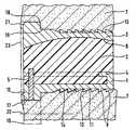
도3은 시상 단면도를 도2에 대응하는 축척으로 도시한다.FIG. 3 shows a sagittal cross section on a scale corresponding to FIG. 2.
보철물은 단단하고 저항성인 재료, 특히 금속의 하부 커버 플레이트(1)와, 폴리에틸렌 또는 양호한 미끄럼 특성을 갖는 다른 플라스틱으로 구성된 보철물 코어(2)와, 하부 커버 플레이트(1)와 동일한 재료로 구성될 수 있는 상부 커버 플레이트(3)로 구성된다. 보철물 코어(2)는 견고하지만 탈착식으로 하부 커버 플레이트(1)와 연결된다. 연결은 상보적인 홈을 구비한 보철물 코어(2)가 삽입될 수 있 는 하부 커버 플레이트(1)의 등쪽 측면 및 양 측면 상의 언더컷 레지(4)에 의해 달성된다. 삽입된 위치에서, 보철물 코어는 볼트(5)에 의해 고정된다. 보철물 코어(2) 및 상부 커버 플레이트(3)는 상호 작용하며 상보적이고 양호하게는 구형인 미끄럼 표면(6)을 형성한다.The prosthesis may be composed of a hard and resistant material, in particular a lower cover plate 1 of metal, a prosthetic core 2 made of polyethylene or other plastic with good sliding properties, and the same material as the lower cover plate 1 Consisting of an
각각 관련 추골(7)과 대면하는 커버 플레이트(1, 3)의 표면들은 동일하게 형성된다. 그들 표면의 많은 부분은 톱니가 형성된, 즉 배쪽 측면을 향한 가파른 플랭크(10) 및 등쪽 측면을 향한 덜 가파른 플랭크(11)를 구비한 복수의 톱니로 덮인다. 가파른 플랭크는 양호하게는 커버 플레이트의 연장 평면에 대해 대체로 직교한다.The surfaces of the
톱니는 시상 중심 축(8)에 대해 횡단하여 연장되며 중간에서 단속되어 홈(12)을 형성하는 리브의 형태를 갖는다. 홈(12)의 영역 내에는 톱니가 없다. 도시된 예에서, 홈의 바닥 표면(13)은 톱니의 바닥 표면과 일치하고 도3에서 점선으로 표시되어 있다. 그러나, 홈은 더 깊거나 더 얕을 수도 있다. 중심에 배열된 홈 대신에, 표면을 가로질러 분포된 복수의 더 좁은 홈이 제공될 수도 있다. 대칭 배열이 적절하다. 홈을 향한 톱니의 측면 단부면은 보철물의 삽입 후에 인접한 뼈 기질과 협동하여, 뼈에 대한 보철물의 측방 변위에 대한 저항을 발생시킨다. 이러한 저항은 홈(12) 내로 성장하는 뼈 기질에 의해 계속되는 사용 중에 증가한다.The tooth is in the form of a rib extending transverse to the sagittal
이러한 효과는 홈 대신에, 톱니를 형성하는 리브의 연장선에 대해 횡단하여 배열된 하나 이상의 리브에 의해 발생될 수 있다. 이러한 리브는 보철물의 삽입 시에 뼈 기질 내로 쉽게 관통하여 각각의 관련 뼈 표면 상에서의 커버 플레이트 표면의 억지 끼워 맞춤의 즉각적인 생성을 방해하지 않도록 좁고 예리해야 한다.This effect may be caused by one or more ribs arranged transverse to the extension of the ribs forming the teeth, instead of the grooves. These ribs should be narrow and sharp so that they can easily penetrate into the bone matrix upon insertion of the prosthesis and do not interfere with the immediate creation of an interference fit of the cover plate surface on each relevant bone surface.
보철물 표면과 뼈 표면 사이의 밀접한 접촉을 촉진하기 위해, 보철물 표면은 뼈 기질이 성장해 들어가는 세공을 가지며 그리고/또는 뼈 기질의 고착을 생물학적으로 촉진하는 코팅(14)을 구비할 수 있다.To facilitate intimate contact between the prosthetic surface and the bone surface, the prosthetic surface may have a
도2 및 도3에 도시된 제1 실시예에서, 커버 플레이트(1, 3)는 배쪽 모서리에서 톱니를 보유하는 표면을 넘어 위쪽 방향 또는 아래쪽 방향으로 돌출하는 리지형 돌출부(15)를 구비한다. 돌출부가 도3에서 알 수 있는 바와 같이 낮은 높이만을 갖지만, 돌출부는 그의 대체로 평평하게 연장되는 형태 때문에 플랜지로서 불린다. 이러한 플랜지는 삽입 시에, 그의 등쪽을 향한 멈춤 표면(16)이 관련 추골(7)의 배쪽 제한 표면(17) 전방에 놓이도록 위치될 수 있다. 그러나, 해부학적 상태에 따라 보철물 부품이 인접한 추골의 기준면(23)을 넘어 배쪽으로 돌출하여 거기서 식도 또는 다른 장기의 자극을 일으키는 것이 그러한 배열과 관련될 수 있기 때문에, (도3에 도시된 바와 같은) 플랜지(15)가 뼈 속으로 들어가는 수술 기술이 양호하다. 바꾸어 말하면, 소량의 재료가 플랜지(15)에 대응하는 형상 및 크기를 가지며 삽입 후에 플랜지를 수납하는 리세스가 생성되도록 추골의 배쪽 가장자리에서 제거된다. 그 다음 플랜지의 멈춤 표면(16)은 이러한 리세스의 배쪽 단부면에 대해 놓인다. 이러한 단부면 상에서의 멈춤 표면(16)의 타이트한 맞닿음을 가능케 하기 위해, 플랜지의 모서리(18)는 라운딩될 수 있다. 뼈가 너무 많이 약해지지 않도록, 이는 플랜지가 톱니를 보유하는 표면 위에서 낮은 높이만을 갖는 것을 요구한다. 이러한 높이는 0.5 내지 2 mm 정도, 양호하게는 0.8 내지 1.3 mm 사이이어야 한다. 전후 방향(AP 방향)으로의 삽입물의 최대 치수의 분율로 표현하면, 이는 양호하게는 1/20 내지 2/10이다.In the first embodiment shown in Figs. 2 and 3, the
플랜지의 낮은 높이는 삽입물의 크기가 플랜지가 고정 부재(예를 들어, 나사 구멍)를 구비하는 실시예에 비해 크게 감소되는 장점을 갖는다. 감소된 치수는 예를 들어 내시경 삽입 시에 대응하여 감소된 직경의 수술 개구 또는 삽입 채널을 통한 삽입을 가능케 한다.The low height of the flange has the advantage that the size of the insert is greatly reduced compared to embodiments where the flange has a fastening member (eg threaded hole). The reduced dimension allows for insertion through a surgical opening or insertion channel of correspondingly reduced diameter, for example in endoscope insertion.
본 발명에 따른 보철물은 등쪽 "공급 작용"을 일으키는 톱니가 원치 않는 배쪽 방향으로의 변위를 방지하며 플랜지가 보철물의 등쪽을 향한 이동을 제한하는 매우 견고한 맞춤을 제공한다. 따라서, 플랜지(15)의 멈춤 표면(16)이 관련 추골 또는 추골 내에 생성된 리세스의 대응하는 배쪽 면에 대해 맞닿는 삽입 시에 선택된 위치가 유지된다.The prosthesis according to the invention provides a very rigid fit that prevents the teeth causing the dorsal "feeding action" from shifting in the unwanted dorsal direction and limits the movement of the flange toward the dorsal side. Thus, the selected position is maintained upon insertion where the
톱니에 의해 달성되는 보철물 끼움의 안전성은 보철물이 인접한 추골들 사이에 충분한 가압에 의해 놓이는 것에 의존한다. 이러한 가압은 통상 후방 종방향 인대가 유지되면 충분하다. 이것이 가능하지 않으면, 의사는 뼈 나사에 의한 추가의 고정을 선호할 것이다. 이를 위해, 플랜지(15)가 일점 쇄선에 의해 표시된 뼈 나사(20)를 수납하는 역할을 하는 나사 구멍을 포함하는 설계가 제공된다. 이러한 설계는 수술 의사가 뼈의 특질이 보철물을 억지 끼워 맞춤 및 톱니에 의해서만 견고하게 고정시키기에 충분한 지를 의심할 때 추천될 수도 있다.The safety of the prosthesis fit achieved by the teeth depends on the prosthesis being placed by sufficient pressure between adjacent vertebrae. This pressurization is usually sufficient if a posterior longitudinal ligament is maintained. If this is not possible, the surgeon will prefer further fixation by bone screws. To this end, a design is provided in which the
각각의 경우에 인접한 장기의 임의의 자극을 회피하거나 최소화하기 위해, 인접한 추골의 기준면을 넘어 배쪽으로 돌출할 수 있는 모든 모서리가 예를 들어 모서리(21)에서 알 수 있는 바와 같이 양호하게 라운딩될 수 있다.In each case, in order to avoid or minimize any irritation of adjacent organs, all corners that can protrude into the abdomen beyond the reference plane of the adjacent vertebrae can be well rounded, for example as seen at
보철물의 톱니는 보철물이 삽입 직후에 인접한 추골에 대한 그의 최종 위치에 도달하도록 미세해야 한다. 바꾸어 말하면, 톱니가 이후에 인접한 추골들 사이에서 일어나는 가압 하에서 톱니에 의해 추골 내로 무시할 만한 범위보다 더 많이 강하되는 것이 회피되어야 한다. 즉, 척추들 사이의 신경 통로의 단면의 원치 않는 감소가 이와 관련될 것이다. 이러한 관점에서, 0.2 내지 0.6 mm, 양호하게는 0.3 내지 0.5 mm 사이의 톱니의 높이와, 0.4 내지 2 mm, 양호하게는 0.6 내지 1.3 mm의 톱니 팁의 간격이 유용한 것으로 입증되었다.The teeth of the prosthesis should be fine so that the prosthesis reaches its final position relative to the adjacent vertebrae immediately after insertion. In other words, it should be avoided that the teeth fall further than the negligible range into the vertebrae by the teeth under the pressure occurring between the adjacent vertebrae later. In other words, an unwanted reduction in the cross section of the neural pathway between the vertebrae will be relevant. In this respect, the tooth height between 0.2 and 0.6 mm, preferably between 0.3 and 0.5 mm, and the tooth tip spacing between 0.4 and 2 mm, preferably between 0.6 and 1.3 mm, proved useful.
배쪽 멈춤 표면(16)을 형성하는 플랜지는 보철물의 폭을 완전히 가로질러 연장될 필요가 없다. 대신에, 그는 적절하게는 대칭으로 배열된 분리되고 이격된 돌출부로부터 형성될 수도 있다.
본 발명의 제2 실시예에 따르면, 도1에 도시된 두 개의 그러한 돌출부(22)가 충분하다.
국부적 멈춤 표면(16)이 제공되면, 이는 적절하게는 도2에서 알 수 있는 바와 같이 추골의 배쪽 경계면에 대응하여 오목하게 형성된다. 그러나, 플랜지가 추골의 리세스 내로 통합되면, 직선으로 연장되는 멈춤 표면(16)이 적절할 수 있고, 이는 그와 협동하는 리세스의 단부면이 임의의 원하는 방식으로 형성될 수 있으며 직선 형상이 특히 간단하기 때문이다.The flanges forming the
According to a second embodiment of the invention, two
If a
Claims (20)
Translated fromKoreanApplications Claiming Priority (5)
| Application Number | Priority Date | Filing Date | Title |
|---|---|---|---|
| EP02005631AEP1344507A1 (en) | 2002-03-12 | 2002-03-12 | Intervertebral prosthesis for the cervical spine |
| EP02005631.3 | 2002-03-12 | ||
| US10/349,183 | 2003-01-23 | ||
| US10/349,183US7267691B2 (en) | 2002-03-12 | 2003-01-23 | Cervical intervertebral prosthesis |
| PCT/EP2003/001803WO2003075804A1 (en) | 2002-03-12 | 2003-02-21 | Cervical intervertebral prosthesis |
Publications (2)
| Publication Number | Publication Date |
|---|---|
| KR20040091711A KR20040091711A (en) | 2004-10-28 |
| KR100961020B1true KR100961020B1 (en) | 2010-06-01 |
Family
ID=27763369
Family Applications (1)
| Application Number | Title | Priority Date | Filing Date |
|---|---|---|---|
| KR1020047014210AExpired - LifetimeKR100961020B1 (en) | 2002-03-12 | 2003-02-21 | Cervical intervertebral prosthesis |
Country Status (16)
| Country | Link |
|---|---|
| US (1) | US7267691B2 (en) |
| EP (2) | EP1344507A1 (en) |
| JP (1) | JP2005519673A (en) |
| KR (1) | KR100961020B1 (en) |
| CN (1) | CN100536803C (en) |
| AR (1) | AR038939A1 (en) |
| AU (1) | AU2003206943B2 (en) |
| BR (1) | BR0303375B1 (en) |
| CA (1) | CA2476479A1 (en) |
| DE (1) | DE20321074U1 (en) |
| IL (1) | IL163560A (en) |
| MX (1) | MXPA04008812A (en) |
| PL (1) | PL371031A1 (en) |
| RU (1) | RU2282422C2 (en) |
| WO (1) | WO2003075804A1 (en) |
| ZA (1) | ZA200406837B (en) |
Families Citing this family (131)
| Publication number | Priority date | Publication date | Assignee | Title |
|---|---|---|---|---|
| FR2824261B1 (en)* | 2001-05-04 | 2004-05-28 | Ldr Medical | INTERVERTEBRAL DISC PROSTHESIS AND IMPLEMENTATION METHOD AND TOOLS |
| DE50210270D1 (en)* | 2002-03-12 | 2007-07-19 | Cervitech Inc | Intervertebral prosthesis, especially for the cervical spine |
| AU2003226586A1 (en) | 2002-09-19 | 2004-04-08 | Malan De Villiers | Intervertebral prosthesis |
| FR2846550B1 (en) | 2002-11-05 | 2006-01-13 | Ldr Medical | INTERVERTEBRAL DISC PROSTHESIS |
| WO2004066884A1 (en) | 2003-01-31 | 2004-08-12 | Spinalmotion, Inc. | Intervertebral prosthesis placement instrument |
| ZA200506029B (en) | 2003-01-31 | 2006-10-25 | Spinalmotion Inc | Spinal Midline Indicator |
| EP1610740A4 (en)* | 2003-04-04 | 2009-04-08 | Theken Disc Llc | Artificial disc prosthesis |
| US8012212B2 (en) | 2003-04-07 | 2011-09-06 | Nuvasive, Inc. | Cervical intervertebral disk prosthesis |
| US7105024B2 (en) | 2003-05-06 | 2006-09-12 | Aesculap Ii, Inc. | Artificial intervertebral disc |
| US20050143824A1 (en)* | 2003-05-06 | 2005-06-30 | Marc Richelsoph | Artificial intervertebral disc |
| US7291173B2 (en) | 2003-05-06 | 2007-11-06 | Aesculap Ii, Inc. | Artificial intervertebral disc |
| DE10324108B3 (en)* | 2003-05-21 | 2005-01-27 | Aesculap Ag & Co. Kg | Backbone implant is inserted with contracted contact disc which is expanded to optimum area following insertion |
| US7442211B2 (en) | 2003-05-27 | 2008-10-28 | Spinalmotion, Inc. | Intervertebral prosthetic disc |
| US10052211B2 (en) | 2003-05-27 | 2018-08-21 | Simplify Medical Pty Ltd. | Prosthetic disc for intervertebral insertion |
| US7575599B2 (en) | 2004-07-30 | 2009-08-18 | Spinalmotion, Inc. | Intervertebral prosthetic disc with metallic core |
| DE10330698B4 (en)* | 2003-07-08 | 2005-05-25 | Aesculap Ag & Co. Kg | Intervertebral implant |
| DE20310433U1 (en) | 2003-07-08 | 2003-09-04 | Aesculap AG & Co. KG, 78532 Tuttlingen | Surgical device for inserting dual component implant into appropriate space at spine, comprising particularly shaped holding area |
| EP1646336B1 (en)* | 2003-07-22 | 2009-07-08 | Synthes GmbH | Intervertebral implant comprising dome-shaped joint surfaces |
| DE10339170B4 (en) | 2003-08-22 | 2009-10-15 | Aesculap Ag | Intervertebral implant |
| WO2005032431A1 (en)* | 2003-10-02 | 2005-04-14 | Cervitech, Inc. | Cervical intervertebral prosthesis |
| DE20315613U1 (en)* | 2003-10-08 | 2003-12-11 | Aesculap Ag & Co. Kg | Intervertebral implant |
| DE20315611U1 (en)* | 2003-10-08 | 2003-12-11 | Aesculap Ag & Co. Kg | Intervertebral implant |
| FR2860974B1 (en)* | 2003-10-17 | 2006-06-16 | Scient X | PROSTHESIS LUMBAR DISC |
| GB0325421D0 (en)* | 2003-10-30 | 2003-12-03 | Gill Steven S | An intervertebral prosthesis |
| EP1532950B1 (en)* | 2003-11-18 | 2008-03-26 | Zimmer GmbH | Spinal disc prosthesis |
| FR2862866B1 (en)* | 2003-11-28 | 2006-12-15 | Gilles Voydeville | POSTERO-LATERAL INTERVERTEBRAL DISCSTRATE |
| EP2113227B1 (en) | 2004-02-04 | 2015-07-29 | LDR Medical | Intervertebral disc prosthesis |
| FR2865629B1 (en) | 2004-02-04 | 2007-01-26 | Ldr Medical | INTERVERTEBRAL DISC PROSTHESIS |
| EP1570813A1 (en)* | 2004-03-05 | 2005-09-07 | Cervitech, Inc. | Cervical intervertebral disc prosthesis with anti-luxation means, and instrument |
| US8070816B2 (en) | 2004-03-29 | 2011-12-06 | 3Hbfm, Llc | Arthroplasty spinal prosthesis and insertion device |
| DE102004016032B4 (en) | 2004-03-30 | 2006-07-13 | Hjs Gelenk System Gmbh | Artificial intervertebral disc |
| US7175662B2 (en) | 2004-04-01 | 2007-02-13 | Cervitech, Inc. | Cervical intervertebral prosthesis |
| FR2869528B1 (en)* | 2004-04-28 | 2007-02-02 | Ldr Medical | INTERVERTEBRAL DISC PROSTHESIS |
| DE202004009542U1 (en) | 2004-06-16 | 2004-08-12 | Aesculap Ag & Co. Kg | Artificial intervertebral disk, comprising core with intensely curved upper and less curved lower surface |
| US8454699B2 (en) | 2004-06-30 | 2013-06-04 | Synergy Disc Replacement, Inc | Systems and methods for vertebral disc replacement |
| US8172904B2 (en) | 2004-06-30 | 2012-05-08 | Synergy Disc Replacement, Inc. | Artificial spinal disc |
| MXPA06014714A (en) | 2004-06-30 | 2007-06-22 | Synergy Disc Replacement Inc | Artificial spinal disc. |
| US9237958B2 (en) | 2004-06-30 | 2016-01-19 | Synergy Disc Replacement Inc. | Joint prostheses |
| US20060009541A1 (en)* | 2004-07-09 | 2006-01-12 | Yih-Fang Chen | Saturant for friction material containing friction modifying layer |
| US7585326B2 (en) | 2004-08-06 | 2009-09-08 | Spinalmotion, Inc. | Methods and apparatus for intervertebral disc prosthesis insertion |
| WO2006058221A2 (en) | 2004-11-24 | 2006-06-01 | Abdou Samy M | Devices and methods for inter-vertebral orthopedic device placement |
| US20060149371A1 (en)* | 2004-12-10 | 2006-07-06 | Sdgi Holdings, Inc. | Intervertebral prosthetic device and method with locking mechanism |
| FR2879436B1 (en)* | 2004-12-22 | 2007-03-09 | Ldr Medical | INTERVERTEBRAL DISC PROSTHESIS |
| US8083797B2 (en) | 2005-02-04 | 2011-12-27 | Spinalmotion, Inc. | Intervertebral prosthetic disc with shock absorption |
| EP1879527A4 (en)* | 2005-05-02 | 2009-08-26 | Kinetic Spine Technologies Inc | Artificial vertebral body |
| US20060276900A1 (en)* | 2005-06-01 | 2006-12-07 | Carpenter Clyde T | Anatomic total disc replacement |
| EP1736120A1 (en) | 2005-06-22 | 2006-12-27 | Cervitech, Inc. | Intervertebral prosthesis with self-cutting fixation protrusions |
| TWI400066B (en)* | 2005-06-22 | 2013-07-01 | Cervitech Inc | Intervertebral prosthesis with self-tapping fixing projections |
| FR2887762B1 (en) | 2005-06-29 | 2007-10-12 | Ldr Medical Soc Par Actions Si | INTERVERTEBRAL DISC PROSTHESIS INSERTION INSTRUMENTATION BETWEEN VERTEBRATES |
| FR2891135B1 (en)* | 2005-09-23 | 2008-09-12 | Ldr Medical Sarl | INTERVERTEBRAL DISC PROSTHESIS |
| US7927373B2 (en) | 2005-10-31 | 2011-04-19 | Depuy Spine, Inc. | Intervertebral disc prosthesis |
| FR2893838B1 (en)* | 2005-11-30 | 2008-08-08 | Ldr Medical Soc Par Actions Si | PROSTHESIS OF INTERVERTEBRAL DISC AND INSTRUMENTATION OF INSERTION OF THE PROSTHESIS BETWEEN VERTEBRATES |
| US7867279B2 (en) | 2006-01-23 | 2011-01-11 | Depuy Spine, Inc. | Intervertebral disc prosthesis |
| US8252058B2 (en)* | 2006-02-16 | 2012-08-28 | Amedica Corporation | Spinal implant with elliptical articulatory interface |
| WO2007121320A2 (en) | 2006-04-12 | 2007-10-25 | Spinalmotion, Inc. | Posterior spinal device and method |
| US20080051901A1 (en) | 2006-07-28 | 2008-02-28 | Spinalmotion, Inc. | Spinal Prosthesis with Multiple Pillar Anchors |
| WO2008070863A2 (en) | 2006-12-07 | 2008-06-12 | Interventional Spine, Inc. | Intervertebral implant |
| US8465546B2 (en) | 2007-02-16 | 2013-06-18 | Ldr Medical | Intervertebral disc prosthesis insertion assemblies |
| FR2916956B1 (en) | 2007-06-08 | 2012-12-14 | Ldr Medical | INTERSOMATIC CAGE, INTERVERTEBRAL PROSTHESIS, ANCHORING DEVICE AND IMPLANTATION INSTRUMENTATION |
| US8900307B2 (en) | 2007-06-26 | 2014-12-02 | DePuy Synthes Products, LLC | Highly lordosed fusion cage |
| US20090043391A1 (en) | 2007-08-09 | 2009-02-12 | Spinalmotion, Inc. | Customized Intervertebral Prosthetic Disc with Shock Absorption |
| US20090105834A1 (en) | 2007-10-22 | 2009-04-23 | Spinalmotion, Inc. | Dynamic Spacer Device and Method for Spanning a Space Formed upon Removal of an Intervertebral Disc |
| EP2237748B1 (en) | 2008-01-17 | 2012-09-05 | Synthes GmbH | An expandable intervertebral implant |
| US8088163B1 (en) | 2008-02-06 | 2012-01-03 | Kleiner Jeffrey B | Tools and methods for spinal fusion |
| US8764833B2 (en) | 2008-03-11 | 2014-07-01 | Spinalmotion, Inc. | Artificial intervertebral disc with lower height |
| US8936641B2 (en) | 2008-04-05 | 2015-01-20 | DePuy Synthes Products, LLC | Expandable intervertebral implant |
| EP2278941A1 (en) | 2008-05-05 | 2011-02-02 | Spinalmotion Inc. | Polyaryletherketone artificial intervertebral disc |
| US20210378834A1 (en) | 2008-05-22 | 2021-12-09 | Spinal Surgical Strategies, Inc., A Nevada Corporation D/B/A Kleiner Device Labs | Spinal fusion cage system with inserter |
| EP2299944A4 (en) | 2008-07-17 | 2013-07-31 | Spinalmotion Inc | SYSTEM FOR INSTALLING ARTIFICIAL INTERVERTEBRAL DISCS |
| EP2299941A1 (en) | 2008-07-18 | 2011-03-30 | Spinalmotion Inc. | Posterior prosthetic intervertebral disc |
| USD853560S1 (en) | 2008-10-09 | 2019-07-09 | Nuvasive, Inc. | Spinal implant insertion device |
| US9717403B2 (en) | 2008-12-05 | 2017-08-01 | Jeffrey B. Kleiner | Method and apparatus for performing retro peritoneal dissection |
| US8366748B2 (en) | 2008-12-05 | 2013-02-05 | Kleiner Jeffrey | Apparatus and method of spinal implant and fusion |
| US8864654B2 (en) | 2010-04-20 | 2014-10-21 | Jeffrey B. Kleiner | Method and apparatus for performing retro peritoneal dissection |
| USD656610S1 (en) | 2009-02-06 | 2012-03-27 | Kleiner Jeffrey B | Spinal distraction instrument |
| US9247943B1 (en) | 2009-02-06 | 2016-02-02 | Kleiner Intellectual Property, Llc | Devices and methods for preparing an intervertebral workspace |
| US9526620B2 (en) | 2009-03-30 | 2016-12-27 | DePuy Synthes Products, Inc. | Zero profile spinal fusion cage |
| US8906028B2 (en) | 2009-09-18 | 2014-12-09 | Spinal Surgical Strategies, Llc | Bone graft delivery device and method of using the same |
| US9629729B2 (en) | 2009-09-18 | 2017-04-25 | Spinal Surgical Strategies, Llc | Biological delivery system with adaptable fusion cage interface |
| USD750249S1 (en) | 2014-10-20 | 2016-02-23 | Spinal Surgical Strategies, Llc | Expandable fusion cage |
| US20170238984A1 (en) | 2009-09-18 | 2017-08-24 | Spinal Surgical Strategies, Llc | Bone graft delivery device with positioning handle |
| US9060877B2 (en) | 2009-09-18 | 2015-06-23 | Spinal Surgical Strategies, Llc | Fusion cage with combined biological delivery system |
| US10973656B2 (en) | 2009-09-18 | 2021-04-13 | Spinal Surgical Strategies, Inc. | Bone graft delivery system and method for using same |
| US8685031B2 (en) | 2009-09-18 | 2014-04-01 | Spinal Surgical Strategies, Llc | Bone graft delivery system |
| US9186193B2 (en) | 2009-09-18 | 2015-11-17 | Spinal Surgical Strategies, Llc | Fusion cage with combined biological delivery system |
| US9173694B2 (en) | 2009-09-18 | 2015-11-03 | Spinal Surgical Strategies, Llc | Fusion cage with combined biological delivery system |
| US10245159B1 (en) | 2009-09-18 | 2019-04-02 | Spinal Surgical Strategies, Llc | Bone graft delivery system and method for using same |
| USD723682S1 (en) | 2013-05-03 | 2015-03-03 | Spinal Surgical Strategies, Llc | Bone graft delivery tool |
| US9028553B2 (en) | 2009-11-05 | 2015-05-12 | DePuy Synthes Products, Inc. | Self-pivoting spinal implant and associated instrumentation |
| US8764806B2 (en) | 2009-12-07 | 2014-07-01 | Samy Abdou | Devices and methods for minimally invasive spinal stabilization and instrumentation |
| US9393129B2 (en) | 2009-12-10 | 2016-07-19 | DePuy Synthes Products, Inc. | Bellows-like expandable interbody fusion cage |
| US9907560B2 (en) | 2010-06-24 | 2018-03-06 | DePuy Synthes Products, Inc. | Flexible vertebral body shavers |
| US8979860B2 (en) | 2010-06-24 | 2015-03-17 | DePuy Synthes Products. LLC | Enhanced cage insertion device |
| US8623091B2 (en) | 2010-06-29 | 2014-01-07 | DePuy Synthes Products, LLC | Distractible intervertebral implant |
| US9402732B2 (en) | 2010-10-11 | 2016-08-02 | DePuy Synthes Products, Inc. | Expandable interspinous process spacer implant |
| US8353964B2 (en) | 2010-11-04 | 2013-01-15 | Carpenter Clyde T | Anatomic total disc replacement |
| EP3485851B1 (en) | 2011-03-22 | 2021-08-25 | DePuy Synthes Products, LLC | Universal trial for lateral cages |
| US8845728B1 (en) | 2011-09-23 | 2014-09-30 | Samy Abdou | Spinal fixation devices and methods of use |
| US20130226240A1 (en) | 2012-02-22 | 2013-08-29 | Samy Abdou | Spinous process fixation devices and methods of use |
| US9226764B2 (en) | 2012-03-06 | 2016-01-05 | DePuy Synthes Products, Inc. | Conformable soft tissue removal instruments |
| US9198767B2 (en) | 2012-08-28 | 2015-12-01 | Samy Abdou | Devices and methods for spinal stabilization and instrumentation |
| US9320617B2 (en) | 2012-10-22 | 2016-04-26 | Cogent Spine, LLC | Devices and methods for spinal stabilization and instrumentation |
| US10022245B2 (en) | 2012-12-17 | 2018-07-17 | DePuy Synthes Products, Inc. | Polyaxial articulating instrument |
| US9717601B2 (en) | 2013-02-28 | 2017-08-01 | DePuy Synthes Products, Inc. | Expandable intervertebral implant, system, kit and method |
| US9522070B2 (en) | 2013-03-07 | 2016-12-20 | Interventional Spine, Inc. | Intervertebral implant |
| US10478096B2 (en) | 2013-08-13 | 2019-11-19 | Innovative Surgical Solutions. | Neural event detection |
| US10478097B2 (en) | 2013-08-13 | 2019-11-19 | Innovative Surgical Solutions | Neural event detection |
| US10376209B2 (en) | 2013-09-20 | 2019-08-13 | Innovative Surgical Solutions, Llc | Neural locating method |
| US10376208B2 (en) | 2013-09-20 | 2019-08-13 | Innovative Surgical Solutions, Llc | Nerve mapping system |
| US10449002B2 (en) | 2013-09-20 | 2019-10-22 | Innovative Surgical Solutions, Llc | Method of mapping a nerve |
| US11426290B2 (en) | 2015-03-06 | 2022-08-30 | DePuy Synthes Products, Inc. | Expandable intervertebral implant, system, kit and method |
| US10857003B1 (en) | 2015-10-14 | 2020-12-08 | Samy Abdou | Devices and methods for vertebral stabilization |
| USD797290S1 (en) | 2015-10-19 | 2017-09-12 | Spinal Surgical Strategies, Llc | Bone graft delivery tool |
| US11510788B2 (en) | 2016-06-28 | 2022-11-29 | Eit Emerging Implant Technologies Gmbh | Expandable, angularly adjustable intervertebral cages |
| EP3474784A2 (en) | 2016-06-28 | 2019-05-01 | Eit Emerging Implant Technologies GmbH | Expandable and angularly adjustable intervertebral cages with articulating joint |
| US10321833B2 (en) | 2016-10-05 | 2019-06-18 | Innovative Surgical Solutions. | Neural locating method |
| US10744000B1 (en) | 2016-10-25 | 2020-08-18 | Samy Abdou | Devices and methods for vertebral bone realignment |
| US10973648B1 (en) | 2016-10-25 | 2021-04-13 | Samy Abdou | Devices and methods for vertebral bone realignment |
| US10398563B2 (en) | 2017-05-08 | 2019-09-03 | Medos International Sarl | Expandable cage |
| US11344424B2 (en) | 2017-06-14 | 2022-05-31 | Medos International Sarl | Expandable intervertebral implant and related methods |
| US10966843B2 (en) | 2017-07-18 | 2021-04-06 | DePuy Synthes Products, Inc. | Implant inserters and related methods |
| US11045331B2 (en) | 2017-08-14 | 2021-06-29 | DePuy Synthes Products, Inc. | Intervertebral implant inserters and related methods |
| US10869616B2 (en) | 2018-06-01 | 2020-12-22 | DePuy Synthes Products, Inc. | Neural event detection |
| US11179248B2 (en) | 2018-10-02 | 2021-11-23 | Samy Abdou | Devices and methods for spinal implantation |
| US10870002B2 (en) | 2018-10-12 | 2020-12-22 | DePuy Synthes Products, Inc. | Neuromuscular sensing device with multi-sensor array |
| US11446156B2 (en) | 2018-10-25 | 2022-09-20 | Medos International Sarl | Expandable intervertebral implant, inserter instrument, and related methods |
| US11399777B2 (en) | 2019-09-27 | 2022-08-02 | DePuy Synthes Products, Inc. | Intraoperative neural monitoring system and method |
| US11426286B2 (en) | 2020-03-06 | 2022-08-30 | Eit Emerging Implant Technologies Gmbh | Expandable intervertebral implant |
| US11850160B2 (en) | 2021-03-26 | 2023-12-26 | Medos International Sarl | Expandable lordotic intervertebral fusion cage |
| US11752009B2 (en) | 2021-04-06 | 2023-09-12 | Medos International Sarl | Expandable intervertebral fusion cage |
| US12090064B2 (en) | 2022-03-01 | 2024-09-17 | Medos International Sarl | Stabilization members for expandable intervertebral implants, and related systems and methods |
Citations (2)
| Publication number | Priority date | Publication date | Assignee | Title |
|---|---|---|---|---|
| US5306307A (en) | 1991-07-22 | 1994-04-26 | Calcitek, Inc. | Spinal disk implant |
| FR2718635A1 (en) | 1994-04-15 | 1995-10-20 | Axcyl Medical | Vertebral cervical prosthesis |
Family Cites Families (36)
| Publication number | Priority date | Publication date | Assignee | Title |
|---|---|---|---|---|
| CH640131A5 (en) | 1979-10-03 | 1983-12-30 | Sulzer Ag | Complete intervertebral prosthesis |
| CA1146301A (en)* | 1980-06-13 | 1983-05-17 | J. David Kuntz | Intervertebral disc prosthesis |
| US5236460A (en)* | 1990-02-12 | 1993-08-17 | Midas Rex Pneumatic Tools, Inc. | Vertebral body prosthesis |
| FR2659226B1 (en) | 1990-03-07 | 1992-05-29 | Jbs Sa | PROSTHESIS FOR INTERVERTEBRAL DISCS AND ITS IMPLEMENTATION INSTRUMENTS. |
| SU1811822A1 (en)* | 1990-09-18 | 1993-04-30 | Nikolaj A Markov | Endoprosthesis of vertebra |
| RU2020901C1 (en)* | 1991-11-28 | 1994-10-15 | Научно-практический центр имплантатов с памятью формы "Доктор" | Intervertebral disc endoprosthesis |
| US5425773A (en)* | 1992-01-06 | 1995-06-20 | Danek Medical, Inc. | Intervertebral disk arthroplasty device |
| US5258031A (en)* | 1992-01-06 | 1993-11-02 | Danek Medical | Intervertebral disk arthroplasty |
| RU2063730C1 (en)* | 1992-11-02 | 1996-07-20 | Научно-практический центр имплантатов с памятью формы "Доктор" | Device for spondylodesis |
| JPH06178787A (en)* | 1992-12-14 | 1994-06-28 | Shima Yumiko | Centrum spacer with joint, intervertebral cavity measuring device and centrum spacer pattern |
| US5676701A (en)* | 1993-01-14 | 1997-10-14 | Smith & Nephew, Inc. | Low wear artificial spinal disc |
| US5360430A (en)* | 1993-07-29 | 1994-11-01 | Lin Chih I | Intervertebral locking device |
| US20010039454A1 (en)* | 1993-11-02 | 2001-11-08 | John Ricci | Orthopedic implants having ordered microgeometric surface patterns |
| CA2551185C (en)* | 1994-03-28 | 2007-10-30 | Sdgi Holdings, Inc. | Apparatus and method for anterior spinal stabilization |
| RU2097007C1 (en)* | 1994-05-11 | 1997-11-27 | Кедров Андрей Владимирович | Internal vertebral fixing device |
| US5674296A (en)* | 1994-11-14 | 1997-10-07 | Spinal Dynamics Corporation | Human spinal disc prosthesis |
| DE29511146U1 (en) | 1995-06-29 | 1995-11-30 | Ohst, Norbert, Ing., 14712 Rathenow | Spinal implant |
| CA2242645A1 (en) | 1995-12-08 | 1997-06-12 | Robert S. Bray, Jr. | Anterior stabilization device |
| US6190414B1 (en)* | 1996-10-31 | 2001-02-20 | Surgical Dynamics Inc. | Apparatus for fusion of adjacent bone structures |
| RU2128969C1 (en)* | 1997-05-28 | 1999-04-20 | Мошконов Вадим Вавилович | Moshkonov vertebra endoprosthesis (sixth variant) |
| AU8768998A (en)* | 1997-08-04 | 1999-02-22 | Gordon, Maya, Roberts & Thomas Number 1 Llc | Multiple axis intervertebral prosthesis |
| US6146421A (en)* | 1997-08-04 | 2000-11-14 | Gordon, Maya, Roberts And Thomas, Number 1, Llc | Multiple axis intervertebral prosthesis |
| US5865848A (en)* | 1997-09-12 | 1999-02-02 | Artifex, Ltd. | Dynamic intervertebral spacer and method of use |
| WO1999065412A1 (en)* | 1998-06-18 | 1999-12-23 | Pioneer Laboratories, Inc. | Spinal fixation system |
| US6063121A (en)* | 1998-07-29 | 2000-05-16 | Xavier; Ravi | Vertebral body prosthesis |
| US6174311B1 (en)* | 1998-10-28 | 2001-01-16 | Sdgi Holdings, Inc. | Interbody fusion grafts and instrumentation |
| US6547823B2 (en)* | 1999-01-22 | 2003-04-15 | Osteotech, Inc. | Intervertebral implant |
| US6368350B1 (en)* | 1999-03-11 | 2002-04-09 | Sulzer Spine-Tech Inc. | Intervertebral disc prosthesis and method |
| US6936071B1 (en)* | 1999-07-02 | 2005-08-30 | Spine Solutions, Inc. | Intervertebral implant |
| RU2175859C2 (en)* | 2000-01-28 | 2001-11-20 | Афанасьев Вениамин Витальевич | Device for fixation of spinal column |
| FR2805733B1 (en)* | 2000-03-03 | 2002-06-07 | Scient X | DISC PROSTHESIS FOR CERVICAL VERTEBRUS |
| US6610093B1 (en)* | 2000-07-28 | 2003-08-26 | Perumala Corporation | Method and apparatus for stabilizing adjacent vertebrae |
| US6635087B2 (en)* | 2001-08-29 | 2003-10-21 | Christopher M. Angelucci | Laminoplasty implants and methods of use |
| US6979353B2 (en)* | 2001-12-03 | 2005-12-27 | Howmedica Osteonics Corp. | Apparatus for fusing adjacent bone structures |
| RU2303422C2 (en)* | 2002-03-12 | 2007-07-27 | Сервитек Инк. | Intervertebral prosthesis and system of intervertebral prostheses, in peculiar case, for cervical department of vertebral column |
| DE50210270D1 (en)* | 2002-03-12 | 2007-07-19 | Cervitech Inc | Intervertebral prosthesis, especially for the cervical spine |
- 2002
- 2002-03-12EPEP02005631Apatent/EP1344507A1/ennot_activeWithdrawn
- 2003
- 2003-01-23USUS10/349,183patent/US7267691B2/ennot_activeExpired - Lifetime
- 2003-02-21AUAU2003206943Apatent/AU2003206943B2/ennot_activeCeased
- 2003-02-21BRBRPI0303375-9Apatent/BR0303375B1/ennot_activeIP Right Cessation
- 2003-02-21KRKR1020047014210Apatent/KR100961020B1/ennot_activeExpired - Lifetime
- 2003-02-21WOPCT/EP2003/001803patent/WO2003075804A1/enactiveApplication Filing
- 2003-02-21RURU2004130309/14Apatent/RU2282422C2/ennot_activeIP Right Cessation
- 2003-02-21CNCNB03805695XApatent/CN100536803C/ennot_activeExpired - Lifetime
- 2003-02-21CACA002476479Apatent/CA2476479A1/ennot_activeAbandoned
- 2003-02-21PLPL03371031Apatent/PL371031A1/enunknown
- 2003-02-21EPEP03704673Apatent/EP1482876A1/ennot_activeWithdrawn
- 2003-02-21JPJP2003574082Apatent/JP2005519673A/enactivePending
- 2003-02-21ILIL163560Apatent/IL163560A/enactiveIP Right Grant
- 2003-02-21DEDE20321074Upatent/DE20321074U1/ennot_activeExpired - Lifetime
- 2003-02-21MXMXPA04008812Apatent/MXPA04008812A/enactiveIP Right Grant
- 2003-03-11ARARP030100842Apatent/AR038939A1/enunknown
- 2004
- 2004-08-27ZAZA2004/06837Apatent/ZA200406837B/enunknown
Patent Citations (2)
| Publication number | Priority date | Publication date | Assignee | Title |
|---|---|---|---|---|
| US5306307A (en) | 1991-07-22 | 1994-04-26 | Calcitek, Inc. | Spinal disk implant |
| FR2718635A1 (en) | 1994-04-15 | 1995-10-20 | Axcyl Medical | Vertebral cervical prosthesis |
Also Published As
| Publication number | Publication date |
|---|---|
| CN100536803C (en) | 2009-09-09 |
| CA2476479A1 (en) | 2003-09-18 |
| EP1344507A1 (en) | 2003-09-17 |
| WO2003075804A1 (en) | 2003-09-18 |
| DE20321074U1 (en) | 2005-12-01 |
| MXPA04008812A (en) | 2007-07-19 |
| PL371031A1 (en) | 2005-06-13 |
| CN1649552A (en) | 2005-08-03 |
| KR20040091711A (en) | 2004-10-28 |
| AR038939A1 (en) | 2005-02-02 |
| RU2004130309A (en) | 2005-04-10 |
| US20040083000A1 (en) | 2004-04-29 |
| RU2282422C2 (en) | 2006-08-27 |
| BR0303375A (en) | 2004-03-23 |
| IL163560A (en) | 2010-11-30 |
| US7267691B2 (en) | 2007-09-11 |
| IL163560A0 (en) | 2005-12-18 |
| JP2005519673A (en) | 2005-07-07 |
| AU2003206943A1 (en) | 2003-09-22 |
| BR0303375B1 (en) | 2012-01-10 |
| EP1482876A1 (en) | 2004-12-08 |
| AU2003206943B2 (en) | 2008-07-10 |
| ZA200406837B (en) | 2005-11-30 |
Similar Documents
| Publication | Publication Date | Title |
|---|---|---|
| KR100961020B1 (en) | Cervical intervertebral prosthesis | |
| US12144741B2 (en) | Intervertebral implant | |
| US7637950B2 (en) | Intervertebral implant with toothed faces | |
| KR101356241B1 (en) | Intervertebral prosthesis with self-tapping fixed protrusion | |
| AU2006243711B2 (en) | Artificial vertebral body | |
| US6132464A (en) | Vertebral joint facets prostheses | |
| KR100582135B1 (en) | Implants, especially anterior cervical spine | |
| US20080249569A1 (en) | Implant Face Plates | |
| US20040186570A1 (en) | Interbody spinal fusion device | |
| US20040199253A1 (en) | Cervical intervertebral disk prosthesis | |
| KR20060092259A (en) | Intervertebral Implants | |
| US10166114B2 (en) | Intervertebral implant with improved shape of the fixing plate | |
| NZ542551A (en) | Prosthetic joint of cervical intervertebral discs | |
| US20100010634A1 (en) | Biocompatible intervertebral spacer | |
| US11083590B2 (en) | Intersomatic prosthesis with lateral introduction | |
| TWI400066B (en) | Intervertebral prosthesis with self-tapping fixing projections |
Legal Events
| Date | Code | Title | Description |
|---|---|---|---|
| PA0105 | International application | Patent event date:20040910 Patent event code:PA01051R01D Comment text:International Patent Application | |
| PG1501 | Laying open of application | ||
| A201 | Request for examination | ||
| PA0201 | Request for examination | Patent event code:PA02012R01D Patent event date:20080221 Comment text:Request for Examination of Application | |
| E902 | Notification of reason for refusal | ||
| PE0902 | Notice of grounds for rejection | Comment text:Notification of reason for refusal Patent event date:20090828 Patent event code:PE09021S01D | |
| E701 | Decision to grant or registration of patent right | ||
| PE0701 | Decision of registration | Patent event code:PE07011S01D Comment text:Decision to Grant Registration Patent event date:20100329 | |
| GRNT | Written decision to grant | ||
| PR0701 | Registration of establishment | Comment text:Registration of Establishment Patent event date:20100525 Patent event code:PR07011E01D | |
| PR1002 | Payment of registration fee | Payment date:20100525 End annual number:3 Start annual number:1 | |
| PG1601 | Publication of registration | ||
| FPAY | Annual fee payment | Payment date:20130524 Year of fee payment:4 | |
| PR1001 | Payment of annual fee | Payment date:20130524 Start annual number:4 End annual number:4 | |
| FPAY | Annual fee payment | Payment date:20140523 Year of fee payment:5 | |
| PR1001 | Payment of annual fee | Payment date:20140523 Start annual number:5 End annual number:5 | |
| FPAY | Annual fee payment | Payment date:20150522 Year of fee payment:6 | |
| PR1001 | Payment of annual fee | Payment date:20150522 Start annual number:6 End annual number:6 | |
| FPAY | Annual fee payment | Payment date:20160518 Year of fee payment:7 | |
| PR1001 | Payment of annual fee | Payment date:20160518 Start annual number:7 End annual number:7 | |
| FPAY | Annual fee payment | Payment date:20170519 Year of fee payment:8 | |
| PR1001 | Payment of annual fee | Payment date:20170519 Start annual number:8 End annual number:8 | |
| FPAY | Annual fee payment | Payment date:20180514 Year of fee payment:9 | |
| PR1001 | Payment of annual fee | Payment date:20180514 Start annual number:9 End annual number:9 | |
| FPAY | Annual fee payment | Payment date:20190429 Year of fee payment:10 | |
| PR1001 | Payment of annual fee | Payment date:20190429 Start annual number:10 End annual number:10 | |
| PR1001 | Payment of annual fee | Payment date:20200504 Start annual number:11 End annual number:11 | |
| PR1001 | Payment of annual fee | Payment date:20210426 Start annual number:12 End annual number:12 | |
| PC1801 | Expiration of term | Termination date:20230821 Termination category:Expiration of duration |