KR100960682B1 - Charging system - Google Patents
Charging systemDownload PDFInfo
- Publication number
- KR100960682B1 KR100960682B1KR1020087004526AKR20087004526AKR100960682B1KR 100960682 B1KR100960682 B1KR 100960682B1KR 1020087004526 AKR1020087004526 AKR 1020087004526AKR 20087004526 AKR20087004526 AKR 20087004526AKR 100960682 B1KR100960682 B1KR 100960682B1
- Authority
- KR
- South Korea
- Prior art keywords
- charging
- power line
- authentication
- power supply
- box
- Prior art date
- Legal status (The legal status is an assumption and is not a legal conclusion. Google has not performed a legal analysis and makes no representation as to the accuracy of the status listed.)
- Expired - Fee Related
Links
Images


Classifications
- H—ELECTRICITY
- H01—ELECTRIC ELEMENTS
- H01M—PROCESSES OR MEANS, e.g. BATTERIES, FOR THE DIRECT CONVERSION OF CHEMICAL ENERGY INTO ELECTRICAL ENERGY
- H01M10/00—Secondary cells; Manufacture thereof
- H01M10/42—Methods or arrangements for servicing or maintenance of secondary cells or secondary half-cells
- H01M10/44—Methods for charging or discharging
- B—PERFORMING OPERATIONS; TRANSPORTING
- B60—VEHICLES IN GENERAL
- B60L—PROPULSION OF ELECTRICALLY-PROPELLED VEHICLES; SUPPLYING ELECTRIC POWER FOR AUXILIARY EQUIPMENT OF ELECTRICALLY-PROPELLED VEHICLES; ELECTRODYNAMIC BRAKE SYSTEMS FOR VEHICLES IN GENERAL; MAGNETIC SUSPENSION OR LEVITATION FOR VEHICLES; MONITORING OPERATING VARIABLES OF ELECTRICALLY-PROPELLED VEHICLES; ELECTRIC SAFETY DEVICES FOR ELECTRICALLY-PROPELLED VEHICLES
- B60L53/00—Methods of charging batteries, specially adapted for electric vehicles; Charging stations or on-board charging equipment therefor; Exchange of energy storage elements in electric vehicles
- B60L53/10—Methods of charging batteries, specially adapted for electric vehicles; Charging stations or on-board charging equipment therefor; Exchange of energy storage elements in electric vehicles characterised by the energy transfer between the charging station and the vehicle
- B60L53/12—Inductive energy transfer
- B60L53/126—Methods for pairing a vehicle and a charging station, e.g. establishing a one-to-one relation between a wireless power transmitter and a wireless power receiver
- B—PERFORMING OPERATIONS; TRANSPORTING
- B60—VEHICLES IN GENERAL
- B60L—PROPULSION OF ELECTRICALLY-PROPELLED VEHICLES; SUPPLYING ELECTRIC POWER FOR AUXILIARY EQUIPMENT OF ELECTRICALLY-PROPELLED VEHICLES; ELECTRODYNAMIC BRAKE SYSTEMS FOR VEHICLES IN GENERAL; MAGNETIC SUSPENSION OR LEVITATION FOR VEHICLES; MONITORING OPERATING VARIABLES OF ELECTRICALLY-PROPELLED VEHICLES; ELECTRIC SAFETY DEVICES FOR ELECTRICALLY-PROPELLED VEHICLES
- B60L53/00—Methods of charging batteries, specially adapted for electric vehicles; Charging stations or on-board charging equipment therefor; Exchange of energy storage elements in electric vehicles
- B60L53/10—Methods of charging batteries, specially adapted for electric vehicles; Charging stations or on-board charging equipment therefor; Exchange of energy storage elements in electric vehicles characterised by the energy transfer between the charging station and the vehicle
- B60L53/14—Conductive energy transfer
- B—PERFORMING OPERATIONS; TRANSPORTING
- B60—VEHICLES IN GENERAL
- B60L—PROPULSION OF ELECTRICALLY-PROPELLED VEHICLES; SUPPLYING ELECTRIC POWER FOR AUXILIARY EQUIPMENT OF ELECTRICALLY-PROPELLED VEHICLES; ELECTRODYNAMIC BRAKE SYSTEMS FOR VEHICLES IN GENERAL; MAGNETIC SUSPENSION OR LEVITATION FOR VEHICLES; MONITORING OPERATING VARIABLES OF ELECTRICALLY-PROPELLED VEHICLES; ELECTRIC SAFETY DEVICES FOR ELECTRICALLY-PROPELLED VEHICLES
- B60L53/00—Methods of charging batteries, specially adapted for electric vehicles; Charging stations or on-board charging equipment therefor; Exchange of energy storage elements in electric vehicles
- B60L53/60—Monitoring or controlling charging stations
- B60L53/62—Monitoring or controlling charging stations in response to charging parameters, e.g. current, voltage or electrical charge
- B—PERFORMING OPERATIONS; TRANSPORTING
- B60—VEHICLES IN GENERAL
- B60L—PROPULSION OF ELECTRICALLY-PROPELLED VEHICLES; SUPPLYING ELECTRIC POWER FOR AUXILIARY EQUIPMENT OF ELECTRICALLY-PROPELLED VEHICLES; ELECTRODYNAMIC BRAKE SYSTEMS FOR VEHICLES IN GENERAL; MAGNETIC SUSPENSION OR LEVITATION FOR VEHICLES; MONITORING OPERATING VARIABLES OF ELECTRICALLY-PROPELLED VEHICLES; ELECTRIC SAFETY DEVICES FOR ELECTRICALLY-PROPELLED VEHICLES
- B60L53/00—Methods of charging batteries, specially adapted for electric vehicles; Charging stations or on-board charging equipment therefor; Exchange of energy storage elements in electric vehicles
- B60L53/60—Monitoring or controlling charging stations
- B60L53/65—Monitoring or controlling charging stations involving identification of vehicles or their battery types
- H—ELECTRICITY
- H02—GENERATION; CONVERSION OR DISTRIBUTION OF ELECTRIC POWER
- H02J—CIRCUIT ARRANGEMENTS OR SYSTEMS FOR SUPPLYING OR DISTRIBUTING ELECTRIC POWER; SYSTEMS FOR STORING ELECTRIC ENERGY
- H02J50/00—Circuit arrangements or systems for wireless supply or distribution of electric power
- H02J50/005—Mechanical details of housing or structure aiming to accommodate the power transfer means, e.g. mechanical integration of coils, antennas or transducers into emitting or receiving devices
- H—ELECTRICITY
- H02—GENERATION; CONVERSION OR DISTRIBUTION OF ELECTRIC POWER
- H02J—CIRCUIT ARRANGEMENTS OR SYSTEMS FOR SUPPLYING OR DISTRIBUTING ELECTRIC POWER; SYSTEMS FOR STORING ELECTRIC ENERGY
- H02J50/00—Circuit arrangements or systems for wireless supply or distribution of electric power
- H02J50/10—Circuit arrangements or systems for wireless supply or distribution of electric power using inductive coupling
- H—ELECTRICITY
- H02—GENERATION; CONVERSION OR DISTRIBUTION OF ELECTRIC POWER
- H02J—CIRCUIT ARRANGEMENTS OR SYSTEMS FOR SUPPLYING OR DISTRIBUTING ELECTRIC POWER; SYSTEMS FOR STORING ELECTRIC ENERGY
- H02J50/00—Circuit arrangements or systems for wireless supply or distribution of electric power
- H02J50/80—Circuit arrangements or systems for wireless supply or distribution of electric power involving the exchange of data, concerning supply or distribution of electric power, between transmitting devices and receiving devices
- H—ELECTRICITY
- H02—GENERATION; CONVERSION OR DISTRIBUTION OF ELECTRIC POWER
- H02J—CIRCUIT ARRANGEMENTS OR SYSTEMS FOR SUPPLYING OR DISTRIBUTING ELECTRIC POWER; SYSTEMS FOR STORING ELECTRIC ENERGY
- H02J7/00—Circuit arrangements for charging or depolarising batteries or for supplying loads from batteries
- H02J7/00032—Circuit arrangements for charging or depolarising batteries or for supplying loads from batteries characterised by data exchange
- H02J7/00045—Authentication, i.e. circuits for checking compatibility between one component, e.g. a battery or a battery charger, and another component, e.g. a power source
- H—ELECTRICITY
- H02—GENERATION; CONVERSION OR DISTRIBUTION OF ELECTRIC POWER
- H02J—CIRCUIT ARRANGEMENTS OR SYSTEMS FOR SUPPLYING OR DISTRIBUTING ELECTRIC POWER; SYSTEMS FOR STORING ELECTRIC ENERGY
- H02J7/00—Circuit arrangements for charging or depolarising batteries or for supplying loads from batteries
- H02J7/0047—Circuit arrangements for charging or depolarising batteries or for supplying loads from batteries with monitoring or indicating devices or circuits
- H02J7/0048—Detection of remaining charge capacity or state of charge [SOC]
- H—ELECTRICITY
- H02—GENERATION; CONVERSION OR DISTRIBUTION OF ELECTRIC POWER
- H02J—CIRCUIT ARRANGEMENTS OR SYSTEMS FOR SUPPLYING OR DISTRIBUTING ELECTRIC POWER; SYSTEMS FOR STORING ELECTRIC ENERGY
- H02J7/00—Circuit arrangements for charging or depolarising batteries or for supplying loads from batteries
- H02J7/02—Circuit arrangements for charging or depolarising batteries or for supplying loads from batteries for charging batteries from AC mains by converters
- B—PERFORMING OPERATIONS; TRANSPORTING
- B60—VEHICLES IN GENERAL
- B60L—PROPULSION OF ELECTRICALLY-PROPELLED VEHICLES; SUPPLYING ELECTRIC POWER FOR AUXILIARY EQUIPMENT OF ELECTRICALLY-PROPELLED VEHICLES; ELECTRODYNAMIC BRAKE SYSTEMS FOR VEHICLES IN GENERAL; MAGNETIC SUSPENSION OR LEVITATION FOR VEHICLES; MONITORING OPERATING VARIABLES OF ELECTRICALLY-PROPELLED VEHICLES; ELECTRIC SAFETY DEVICES FOR ELECTRICALLY-PROPELLED VEHICLES
- B60L2270/00—Problem solutions or means not otherwise provided for
- B60L2270/30—Preventing theft during charging
- B60L2270/34—Preventing theft during charging of parts
- B—PERFORMING OPERATIONS; TRANSPORTING
- B60—VEHICLES IN GENERAL
- B60L—PROPULSION OF ELECTRICALLY-PROPELLED VEHICLES; SUPPLYING ELECTRIC POWER FOR AUXILIARY EQUIPMENT OF ELECTRICALLY-PROPELLED VEHICLES; ELECTRODYNAMIC BRAKE SYSTEMS FOR VEHICLES IN GENERAL; MAGNETIC SUSPENSION OR LEVITATION FOR VEHICLES; MONITORING OPERATING VARIABLES OF ELECTRICALLY-PROPELLED VEHICLES; ELECTRIC SAFETY DEVICES FOR ELECTRICALLY-PROPELLED VEHICLES
- B60L2270/00—Problem solutions or means not otherwise provided for
- B60L2270/30—Preventing theft during charging
- B60L2270/36—Preventing theft during charging of vehicles
- Y—GENERAL TAGGING OF NEW TECHNOLOGICAL DEVELOPMENTS; GENERAL TAGGING OF CROSS-SECTIONAL TECHNOLOGIES SPANNING OVER SEVERAL SECTIONS OF THE IPC; TECHNICAL SUBJECTS COVERED BY FORMER USPC CROSS-REFERENCE ART COLLECTIONS [XRACs] AND DIGESTS
- Y02—TECHNOLOGIES OR APPLICATIONS FOR MITIGATION OR ADAPTATION AGAINST CLIMATE CHANGE
- Y02E—REDUCTION OF GREENHOUSE GAS [GHG] EMISSIONS, RELATED TO ENERGY GENERATION, TRANSMISSION OR DISTRIBUTION
- Y02E60/00—Enabling technologies; Technologies with a potential or indirect contribution to GHG emissions mitigation
- Y02E60/10—Energy storage using batteries
- Y—GENERAL TAGGING OF NEW TECHNOLOGICAL DEVELOPMENTS; GENERAL TAGGING OF CROSS-SECTIONAL TECHNOLOGIES SPANNING OVER SEVERAL SECTIONS OF THE IPC; TECHNICAL SUBJECTS COVERED BY FORMER USPC CROSS-REFERENCE ART COLLECTIONS [XRACs] AND DIGESTS
- Y02—TECHNOLOGIES OR APPLICATIONS FOR MITIGATION OR ADAPTATION AGAINST CLIMATE CHANGE
- Y02T—CLIMATE CHANGE MITIGATION TECHNOLOGIES RELATED TO TRANSPORTATION
- Y02T10/00—Road transport of goods or passengers
- Y02T10/60—Other road transportation technologies with climate change mitigation effect
- Y02T10/70—Energy storage systems for electromobility, e.g. batteries
- Y—GENERAL TAGGING OF NEW TECHNOLOGICAL DEVELOPMENTS; GENERAL TAGGING OF CROSS-SECTIONAL TECHNOLOGIES SPANNING OVER SEVERAL SECTIONS OF THE IPC; TECHNICAL SUBJECTS COVERED BY FORMER USPC CROSS-REFERENCE ART COLLECTIONS [XRACs] AND DIGESTS
- Y02—TECHNOLOGIES OR APPLICATIONS FOR MITIGATION OR ADAPTATION AGAINST CLIMATE CHANGE
- Y02T—CLIMATE CHANGE MITIGATION TECHNOLOGIES RELATED TO TRANSPORTATION
- Y02T10/00—Road transport of goods or passengers
- Y02T10/60—Other road transportation technologies with climate change mitigation effect
- Y02T10/7072—Electromobility specific charging systems or methods for batteries, ultracapacitors, supercapacitors or double-layer capacitors
- Y—GENERAL TAGGING OF NEW TECHNOLOGICAL DEVELOPMENTS; GENERAL TAGGING OF CROSS-SECTIONAL TECHNOLOGIES SPANNING OVER SEVERAL SECTIONS OF THE IPC; TECHNICAL SUBJECTS COVERED BY FORMER USPC CROSS-REFERENCE ART COLLECTIONS [XRACs] AND DIGESTS
- Y02—TECHNOLOGIES OR APPLICATIONS FOR MITIGATION OR ADAPTATION AGAINST CLIMATE CHANGE
- Y02T—CLIMATE CHANGE MITIGATION TECHNOLOGIES RELATED TO TRANSPORTATION
- Y02T90/00—Enabling technologies or technologies with a potential or indirect contribution to GHG emissions mitigation
- Y02T90/10—Technologies relating to charging of electric vehicles
- Y02T90/12—Electric charging stations
- Y—GENERAL TAGGING OF NEW TECHNOLOGICAL DEVELOPMENTS; GENERAL TAGGING OF CROSS-SECTIONAL TECHNOLOGIES SPANNING OVER SEVERAL SECTIONS OF THE IPC; TECHNICAL SUBJECTS COVERED BY FORMER USPC CROSS-REFERENCE ART COLLECTIONS [XRACs] AND DIGESTS
- Y02—TECHNOLOGIES OR APPLICATIONS FOR MITIGATION OR ADAPTATION AGAINST CLIMATE CHANGE
- Y02T—CLIMATE CHANGE MITIGATION TECHNOLOGIES RELATED TO TRANSPORTATION
- Y02T90/00—Enabling technologies or technologies with a potential or indirect contribution to GHG emissions mitigation
- Y02T90/10—Technologies relating to charging of electric vehicles
- Y02T90/14—Plug-in electric vehicles
- Y—GENERAL TAGGING OF NEW TECHNOLOGICAL DEVELOPMENTS; GENERAL TAGGING OF CROSS-SECTIONAL TECHNOLOGIES SPANNING OVER SEVERAL SECTIONS OF THE IPC; TECHNICAL SUBJECTS COVERED BY FORMER USPC CROSS-REFERENCE ART COLLECTIONS [XRACs] AND DIGESTS
- Y02—TECHNOLOGIES OR APPLICATIONS FOR MITIGATION OR ADAPTATION AGAINST CLIMATE CHANGE
- Y02T—CLIMATE CHANGE MITIGATION TECHNOLOGIES RELATED TO TRANSPORTATION
- Y02T90/00—Enabling technologies or technologies with a potential or indirect contribution to GHG emissions mitigation
- Y02T90/10—Technologies relating to charging of electric vehicles
- Y02T90/16—Information or communication technologies improving the operation of electric vehicles
- Y02T90/167—Systems integrating technologies related to power network operation and communication or information technologies for supporting the interoperability of electric or hybrid vehicles, i.e. smartgrids as interface for battery charging of electric vehicles [EV] or hybrid vehicles [HEV]
- Y—GENERAL TAGGING OF NEW TECHNOLOGICAL DEVELOPMENTS; GENERAL TAGGING OF CROSS-SECTIONAL TECHNOLOGIES SPANNING OVER SEVERAL SECTIONS OF THE IPC; TECHNICAL SUBJECTS COVERED BY FORMER USPC CROSS-REFERENCE ART COLLECTIONS [XRACs] AND DIGESTS
- Y04—INFORMATION OR COMMUNICATION TECHNOLOGIES HAVING AN IMPACT ON OTHER TECHNOLOGY AREAS
- Y04S—SYSTEMS INTEGRATING TECHNOLOGIES RELATED TO POWER NETWORK OPERATION, COMMUNICATION OR INFORMATION TECHNOLOGIES FOR IMPROVING THE ELECTRICAL POWER GENERATION, TRANSMISSION, DISTRIBUTION, MANAGEMENT OR USAGE, i.e. SMART GRIDS
- Y04S30/00—Systems supporting specific end-user applications in the sector of transportation
- Y04S30/10—Systems supporting the interoperability of electric or hybrid vehicles
- Y04S30/14—Details associated with the interoperability, e.g. vehicle recognition, authentication, identification or billing
Landscapes
- Engineering & Computer Science (AREA)
- Power Engineering (AREA)
- Transportation (AREA)
- Mechanical Engineering (AREA)
- Computer Networks & Wireless Communication (AREA)
- Chemical & Material Sciences (AREA)
- Manufacturing & Machinery (AREA)
- Chemical Kinetics & Catalysis (AREA)
- Electrochemistry (AREA)
- General Chemical & Material Sciences (AREA)
- Electric Propulsion And Braking For Vehicles (AREA)
- Charge And Discharge Circuits For Batteries Or The Like (AREA)
- Burglar Alarm Systems (AREA)
- Remote Monitoring And Control Of Power-Distribution Networks (AREA)
- Secondary Cells (AREA)
Abstract
Translated fromKoreanDescription
Translated fromKorean본 발명은 가정용 전력 공급기(household power supply)로부터 충전 대상(charging subject), 또는 재충전 가능한 배터리로 전력을 공급하기 위한 충전 시스템(charging system)에 관한 것이다.The present invention relates to a charging system for supplying power from a household power supply to a charging subject, or a rechargeable battery.
지난 몇 년간, 오직 엔진에 의해서만 구동되는 엔진 자동차(engine automobile)와 다른 타입의 자동차인 하이브리드 자동차(hybrid vehicle) 및 전기 자동차(electric vehicle)가 대중화되고 있다. 오직 엔진에 의해서만 전력을 공급받는 엔진 자동차와는 다른 타입의 자동차로서, 하이브리드 자동차는 엔진과 모터를 모두 사용하는 구동원(drive source)에 의하여 구동되고, 전기 자동차는 모터에 의해 구동된다. 이러한 타입의 전기적으로 구동되는(electrically-driven) 자동차에서는, 배터리의 전압이 감소하면 상기 배터리가 충전되어야만 한다. 가정용 전력 공급기(예를 들어, AC 100V의 상업용 전력 공급기)를 사용하여 배터리를 충전할 경우, 충전 케이블(charging cable)과 같은 외부 충전 장치(external charging device)의 입력을 가정용 소켓(household socket)에 연결하고 상기 외부 충전 장치의 출력을 자동차의 충전 커넥터(charging connector)에 연결함으로써 상기 배터리를 충전할 수 있다.In the last few years, hybrid vehicles and electric vehicles, engine engines and other types of vehicles driven only by engines, have become popular. As a type of vehicle different from an engine vehicle powered only by an engine, a hybrid vehicle is driven by a drive source using both an engine and a motor, and an electric vehicle is driven by a motor. In electrically driven vehicles of this type, the battery must be charged when the voltage of the battery decreases. When charging the battery using a domestic power supply (for example, a commercial power supply of AC 100V), connect the input of an external charging device, such as a charging cable, to the household socket. The battery can be charged by connecting and connecting the output of the external charging device to a charging connector of a vehicle.
가정용 전력 공급기를 사용하여 상기 배터리를 충전할 때, 상기 전동(electrically-driven) 자동차의 배터리는, 가정용 소켓에 단지 상기 외부 충전 장치의 플러그를 꽂음으로써, 상기 가정용 소켓으로부터 공급된 전력에 의하여 아무런 제약 없이 충전될 수 있다. 그러므로, 상기 전동 자동차를 도난 당하면, 상기 외부 충전 장치를 사용함으로써 상기 도난 당한 자동차의 배터리가 가정용 전력 공급기에 의하여 반복적으로 충전될 수 있기 때문에, 도둑은 상기 훔친 자동차를 계속 운전할 수 있을 것이다. 이것이 전동 자동차의 도난을 야기하는 하나의 요인이 된다. 따라서, 자동차 도난을 줄이기 위한 도난 방지 대책이 요구된다.When charging the battery using a household power supply, the battery of the electrically-driven vehicle is not restricted by the power supplied from the household socket by simply plugging the external charging device into the household socket. Can be charged without Therefore, if the electric vehicle is stolen, the thief will be able to continue driving the stolen car because the battery of the stolen vehicle can be repeatedly charged by the household power supply by using the external charging device. This is one factor that causes theft of electric vehicles. Accordingly, antitheft measures are required to reduce theft of automobiles.
특허문헌 1[일본국 특허공개 평10-262303호 공보]에는 전동 자동차의 도난을 방지할 수 있도록 전동 자동차의 배터리 충전에 대한 충전 인증 시스템의 예가 개시되어 있다. 이 기술은 자동차 키로서 사용되는 IC 카드로부터 정보를 독출하고 상기 IC 카드에 정보를 기입할 수 있는 기입-독출 장치를 사용한다. 상기 충전 시스템을 사용하여 충전을 수행하는 경우, 권한을 가진 사용자는 상기 자동차로부터 상기 IC 카드를 제거하고 그것을 상기 기입-독출 장치에 삽입한다. 상기 IC 카드가 인증되면, 배터리를 충전할 수 있다.Patent Document 1 (Japanese Patent Laid-Open No. 10-262303) discloses an example of a charge authentication system for charging a battery of an electric vehicle so as to prevent theft of the electric vehicle. This technique uses a write-reading device that can read information from and write information to an IC card used as a car key. When performing charging using the charging system, an authorized user removes the IC card from the vehicle and inserts it into the write-read device. If the IC card is authenticated, the battery can be charged.
그러나, IC 카드의 인증 획득을 통하여 충전행위를 제한하는 기술을 사용하는 경우라도, 상기 IC 카드를 도난 당하면 상기 배터리는 여전히 충전될 수 있다. 이러한 경우, 이 기술은 효력이 없다. 특히, IC 카드의 주인은 보통 상기 IC 카드를 가지고 다니기 때문에, 상기 주인이 주의 깊지 않으면 상기 IC 카드를 도난 당할 수 있다. 따라서, 가정용 전력 공급기를 이용하여 충전이 수행될 때 인증을 수 행하는 시스템을 채용하더라도 자동차 도난의 방지가 충분히 보장되지 않는다.However, even in the case of using a technique of limiting the charging behavior through authentication of the IC card, the battery can still be charged if the IC card is stolen. In this case, this technique is not effective. In particular, since the owner of the IC card usually carries the IC card, the IC card may be stolen if the owner is not careful. Therefore, even if a system employing a system for performing authentication when charging is performed using a household power supply is not sufficiently secured against theft of the automobile.
본 발명은 충전 대상의 도난을 충분히 방지할 수 있는 충전 시스템을 제공한다.The present invention provides a charging system capable of sufficiently preventing theft of a charging target.
본 발명의 제 1 측면은 가정용 전력 공급기를 이용하는 충전 시스템에 관한 것이다. 상기 충전 시스템은 재충전 가능한 배터리를 포함하는 충전 대상을 포함한다. 전력선은 상기 충전 대상의 상기 재충전 가능한 배터리 및 상기 가정용 전력 공급기에 연결 가능하다. 상기 전력 공급기에 연결 가능한 인증 관리 장치는 상기 전력선의 적어도 부분을 통하여 상기 충전 대상의 인증을 수행한다. 상기 인증 관리 장치와 상기 충전 대상에 상기 인증이 확립된 경우 상기 충전 대상은 상기 전력 공급기를 이용한 상기 재충전 가능한 배터리의 충전을 허가한다.A first aspect of the invention relates to a charging system using a domestic power supply. The charging system includes a charging object including a rechargeable battery. A power line is connectable to the rechargeable battery of the charging target and the household power supply. An authentication management device connectable to the power supply performs authentication of the charging target through at least a portion of the power line. When the authentication is established in the authentication management device and the charging target, the charging target allows charging of the rechargeable battery using the power supply.
본 발명의 제 2 측면은 가정용 전력 공급기를 이용하는 충전 시스템에 관한 것이다. 상기 충전 시스템은 재충전 가능한 배터리를 포함하는 충전 대상을 포함한다. 전력선은 상기 충전 대상의 상기 재충전 가능한 배터리 및 상기 가정용 전력 공급기에 연결 가능하다. 상기 전력 공급기에 연결 가능한 인증 관리 장치는 상기 전력선으로부터 독립적으로 배열된 전기 배선을 통하여 상기 충전 대상의 인증을 수행한다. 상기 인증 관리 장치와 상기 충전 대상에 인증이 확립된 경우 상기 충전 대상은 상기 전력 공급기를 이용한 상기 재충전 가능한 배터리의 충전을 허가한다.A second aspect of the invention relates to a charging system using a domestic power supply. The charging system includes a charging object including a rechargeable battery. A power line is connectable to the rechargeable battery of the charging target and the household power supply. An authentication management device connectable to the power supply performs authentication of the charging target through an electrical wire arranged independently from the power line. When authentication is established in the authentication management device and the charging target, the charging target permits charging of the rechargeable battery using the power supply.
도 1은 본 발명의 제 1 실시예에 따른 충전 시스템의 구조를 나타내는 개략 적인 블록도이다.1 is a schematic block diagram showing the structure of a charging system according to a first embodiment of the present invention.
도 2는 자동차 충전 연결을 위한 코일을 이용하는 상기 충전 시스템의 구조를 나타내는 개략도이다.2 is a schematic diagram showing the structure of the charging system using a coil for automobile charging connection.
도 3은 본 발명의 제 2 실시예에 따른 ID 박스의 구조를 나타내는 개략적인 블록도이다.3 is a schematic block diagram showing the structure of an ID box according to a second embodiment of the present invention.
도 4는 본 발명의 제 3 실시예에 따른 충전 시스템의 구조를 나타내는 개략적인 블록도이다.4 is a schematic block diagram showing the structure of a charging system according to a third embodiment of the present invention.
도 5는 본 발명의 제 4 실시예에 따른 ID 박스 시스템 장치의 구조를 나타내는 개략적인 블록도이다.5 is a schematic block diagram showing the structure of an ID box system apparatus according to a fourth embodiment of the present invention.
도 6는 본 발명의 제 5 실시예에 따른 ID 박스 시스템 장치의 플러그를 통합한 자동차 키의 구조를 나타내는 개략적인 사시도이다.6 is a schematic perspective view showing the structure of a car key incorporating a plug of the ID box system apparatus according to the fifth embodiment of the present invention.
[제 1 실시예][First Embodiment]
이하, 도 1 및 도 2를 참조하여 본 발명의 제 1 실시예에 따른 충전 시스템을 설명한다.Hereinafter, a charging system according to a first embodiment of the present invention will be described with reference to FIGS. 1 and 2.
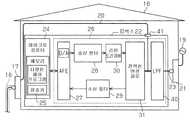
도 1을 참조하면, 자동차(1)는 전동 자동차(electrically-driven vehicle)이고, 모터 시스템(3)은 상기 전동 자동차를 구동할 때 자동차 전력원으로 사용되는 모터(2)의 구동제어를 위하여 자동차(1)에 설치된다. 모터 시스템(3)은, 변속 레버(gearshift lever)가 주차 위치에 놓이고 브레이크 페달이 눌러진 동안, 엔진 시스템의 작동 스위치(미도시)를 조작함으로써 비활성 상태에서 활성화된다. 모터 시 스템(3)은, 상기 변속 레버가 주차 위치에 놓이고 자동차 속도가 “0”인 동안, 상기 작동 스위치를 조작함으로써 활성 상태에서 비활성화된다. 자동차(1)는 충전대상일 수 있다.Referring to FIG. 1, a motor vehicle 1 is an electrically-driven vehicle, and the motor system 3 is a motor vehicle for driving control of a
모터 시스템(3)은 자동차(1)의 구동을 제어하는 모터 제어 ECU(4)를 포함한다. 구동원으로 작용하는 모터(2)는 인버터(5)를 통하여 모터 제어 ECU(4)에 연결된다. 모터 제어 ECU(4)는 모터(2)가 가속 페달 변위, 기어 위치 및 다양한 센서들로부터의 출력 신호들에 기초한 동작 상태에 상응하는 회전력을 가지도록 모터(2)의 구동을 제어한다. 이에 따라, 모터 제어 ECU(4)는 계산된 모터 회전력에 상응하는 전류를 생성함으로써 모터(2)를 구동한다.The motor system 3 includes a motor control ECU 4 which controls the driving of the motor vehicle 1. The
모터(2)에 전력을 공급하는 배터리(6)는 자동차(1)에 설치된다. 배터리(6)는 복수의 직렬 연결된 전지들을 포함하는 배터리 모듈(7), 및 배터리 모듈(7)의 고전압 전력 공급 회로(8)에 직렬로 연결된 시스템 주 릴레이(9)를 포함한다. 인버터(5)는 고전압 및 고전류를 공급할 수 있는 파워 케이블(10)에 의하여 모터(2)에 연결된다. 다른 파워 케이블(10)은 인버터(5)를 배터리(6)에 연결한다. 시스템 주 릴레이(9)는 전기 배선들을 통하여 모터 제어 ECU(4)에 연결된다. 모터 제어 ECU(4)는 시스템 주 릴레이(9)에 대한 고전압 전력 공급 회로(8)의 연결 커맨드 또는 차단 커맨드를 생성한다. 배터리(6)는 재충전 가능한 배터리일 수 있다.The
배터리(6)의 충전을 모니터링하는 충전 제어 ECU(11)는 캔(controller area network, CAN) 통신을 통하여 모터 제어 ECU(4)에 연결된다. 고전압 전력 공급 회로(8)로 흐르는 전류량을 검출하는 전류 센서(12)는 충전 제어 ECU(11)에 연결된 다. 충전 제어 ECU(11)에 고전압 전력 공급 회로(8)로 흐르는 전류량에 상응하는 검출 신호를 제공하기 위하여 전류 센서(12)는 고전압 전력 공급 회로(8)의 배선을 통하여 배터리 모듈(7)에 직렬로 연결된다.The
충전 모니터링 제어 프로그램이 충전 제어 ECU(11) 내의 ROM 및 EEPROM을 포함하는 메모리(13)에 작성된다. 충전 제어 ECU(11)는 충전 상태 (충전이 수행되는 지의 여부) 모니터링, 충전 양 (전하의 상태) 모니터링 등과 같은 처리를 수행하도록 상기 충전 모니터링 제어 프로그램에 따라 작동한다. 그러면, 충전 제어 ECU(11)는 처리 결과(충전 정보)를 모터 제어 ECU(4)에 제공한다. 모터 제어 ECU(4)는 충전 제어 ECU(11)로부터 제공된 상기 충전 정보에 기초하여 충전 상태 및 배터리(6)의 충전 양을 인식한다.The charge monitoring control program is created in the
고전압 전력 공급 회로(8)의 활성화 및 비활성화를 위한 스위치(14)는 고전압 전력 공급 회로(8)에 직렬로 연결된다. 배터리(6), 전류 센서(12) 및 스위치(14)를 포함하는 직렬 연결된 회로는 충전 커넥터(15)에 병렬로 연결된다. 스위치(14)는 평상시 닫혀있도록 설정될 수 있다. 또한, 스위치(14)는 충전 전에 ECU(11)가 충전을 중단하도록 제어할 때 열릴 수 있고, 이러한 경우 배터리(6)는 충전될 수 없다. 스위치(14)는 전기 배선을 통하여 충전 제어 ECU(11)에 연결되고, 충전 제어 ECU(11)로부터의 커맨드들에 응답하여 단속된다.A
배터리(6)가 충전될 때 전기적 주입구로서 작용하는 충전 커넥터(15)는 자동차(1)에 배치된다. 충전 커넥터(15)는 배터리 모듈(7) 및 전류 센서(12)의 상기 직렬 연결된 회로에 직렬로 연결된다. 충전 케이블(18)의 일단은 충전 커넥터(15)에 연결된다. 또한, 충전 케이블(18)의 타단은 가옥(16)의 옥외 콘센트(17)에 삽입 가능하다. 충전 케이블(18)이 충전 커넥터(15)와 옥외 콘센트(17)를 연결할 경우, 배터리(6)를 충전하도록 충전 케이블(18)의 전력선을 통하여 가옥(16)의 가정용 전력 공급기(예를 들어, AC 100V의 상업용 전력 공급기)(19)에서 배터리(6)로 전류가 흐른다. 충전 케이블(18)은 상기 전력선을 형성하고, 가정용 전력 공급기(19)는 전력 공급기에 상응한다.The charging
옥외 콘센트(17)는 전류 경로로서 실내에 배치되는 실내 전력선(20)에 의하여 실내 콘센트(21)에 연결된다. 실내 콘센트(21)는 가정용 전력 공급기(19)에 연결된다. 배터리(6)를 충전할 때 암호(code)들을 통하여 충전 제어 ECU(11)와 인증을 수행하기 위한 ID 박스(22)는 실내 콘센트(21)에 연결된다. ID 박스(22)는 단일 독립 유닛을 구성하는 인증 장치이다. ID 박스(22)의 케이스 밖으로 연장된 연결 코드(23)는 실내 콘센트(21)에 연결 가능하다. 실내 전력선(20)은 전력선(제 2 전력선 또는 분기된 전력선)을 형성한다. 실내 콘센트(21)는 콘센트에 상응하고, ID 박스(22)는 인증 관리 장치를 구성한다.The
ID 박스(22)는 전력선 통신을 통하여 충전 제어 ECU(11)와 데이터 통신을 수행하는 마이크로컴퓨터(24)를 포함한다. 마이크로컴퓨터(24)는 메모리(25)에 충전 제한 프로그램을 저장한다. 마이크로컴퓨터(24)는 상기 충전 제한 프로그램에 따라 충전 제어 ECU(11)와 ID 박스(22) 사이의 인증을 수행하고, 인증이 확립되는 것을 조건으로 배터리(6)의 충전을 허가한다. 인증을 위한 암호키(code key)는 마이크로컴퓨터(24)의 메모리(25)에 기록되고, 동일한 암호키가 충전 제어 ECU(11)의 메모 리(13)에도 기록된다. 따라서, 상기 암호키들은 충전 제어 ECU(11)와 ID 박스(22)가 모두 진정할(authentic) 때 대응(match)된다.The
전력선 통신이 수행될 때 동작하는 가정용 전력선 통신 모듈(26)은 마이크로컴퓨터(24)에 연결된다. 가정용 전력선 통신 모듈(26)은 마이크로컴퓨터(24)에 연결되고 신호 변환기로 작용하는 아날로그 프론트 엔드(AFE, 27)를 포함한다.The home power
마이크로컴퓨터(24)에서 충전 제어 ECU(11)로 송신되는 다양한 신호들에 대한 송신 처리를 수행하는 송신 필터(28) 및 실내 전력선(20)과 같은 전력선들을 통하여 ID 박스(22)에 의해 수신된 다양한 신호들에 대한 수신 처리를 수행하는 수신 필터(29)는 아날로그 프론트 엔드(27)에 연결된다. 예를 들어, 송신 필터(28)는 데이터 패킷들의 송신을 위한 처리를 수행한다. 송신 필터(28)는 단일 데이터 유닛을 생성하기 위하여 필요한 데이터를 통합하고, 송신 속도를 조절하고 다중 송신을 제어하기 위하여 상기 데이터 유닛을 패킷들로 구분한다. 수신 필터(29)는 복수의 수신된 패킷들로부터 데이터 유닛을 복구하고 상기 데이터 유닛으로부터 상기 필요한 데이터를 추출하는 처리를 수행한다.Received by the
송신 필터(28)의 출력 신호를 차동 출력으로 변환하는 라인 드라이버(30)는 송신 필터(28)에 연결된다. 가정용 전력선 통신 모듈(26)의 다양한 신호 선들을 전력선 시스템 배선에 연결하는 전력선 연결 회로(31)는 수신 필터(29) 및 라인 드라이버(30)에 연결된다. 전력선 연결 회로(31)로부터 연장된 연결 코드(23)는 실내 콘센트(21)에 연결 가능하다.A
ID 박스(22)에 기록된 충전 제한 프로그램과 유사한 프로그램이 충전 제어 ECU(11)의 메모리(13)에 저장된다. 자동차 전력선 통신 모듈(32)은, 가정용 전력선 통신 모듈(36)과 유사하게, 아날로그 프론트 엔드(33), 송신 필터(34), 수신 필터(35), 라인 드라이버(36) 및 전력선 연결 회로(37)를 포함한다.A program similar to the charge limit program recorded in the
이하, 제 1 실시예에 따른 충전 시스템의 동작을 설명한다.The operation of the charging system according to the first embodiment will now be described.
우선, 자동차(1)의 배터리(6)를 충전할 때, 충전 케이블(18)의 일단이 충전 커넥터(15)에 연결되고, 충전 케이블(18)의 타단이 가옥(16)의 옥외 콘센트(17)에 연결된다. 그러면, 가옥(16)의 가정용 전력 공급기(19)에서 고전압 전력 공급 회로(8)로 전류가 흐르기 시작한다. 이 상태에서, 시스템 주 릴레이(9)는 비활성화되고, 모터 시스템(3)은 활성 상태가 아니다. 충전 제어 ECU(11)는 자동차 전력선 통신 모듈(32)을 통하여 고전압 전력 공급 회로(8)로의 전류를 감지한 경우 배터리(6)의 충전 동작이 시작된 것을 인식한다.First, when charging the
상기 충전 동작이 시작된 경우, 충전 제어 ECU(11)는 ID 박스(22)를 활성화시키기 위하여 아날로그 프론트 엔드(33), 송신 필터(34), 라인 드라이버(36) 및 전력선 연결 회로(37)를 통하여 충전 케이블(즉, 전력선)(18)에 ID 박스 활성화 신호(Swk)를 보낸다. 충전 제어 ECU(11)는 충전 케이블(18) 및 실내 전력선(20)을 사용하여 전력선 통신을 통하여 ID 박스(22)에 ID 박스 활성화 신호(Swk)를 송신한다.When the charging operation is started, the charging
ID 박스(22)는 충전 케이블(18) 및 실내 전력선(20)을 통하여 ID 박스 활성화 신호(Swk)를 수신한다. 마이크로컴퓨터(24)는 전력선 연결 회로(31), 수신 필터(29) 및 아날로그 프론트 엔드(27)를 통하여 ID 박스 활성화 신호(Swk)를 획득한 다.The
ID 박스 활성화 신호(Swk)에 응답하여, ID 박스 활성화 신호(Swk)의 데이터 내용을 해독할 때 마이크로컴퓨터(24)가 활성화된다. 초기화와 같은 다양한 처리들이 수행되고 활성화의 완료가 인식된 후, 마이크로컴퓨터(24)는 아날로그 프론트 엔드(27), 송신 필터(28), 라인 드라이버(30) 및 전력선 연결 회로(31)를 통하여 실내 전력선(20)에 활성화 완료 신호(Sok)를 보낸다. 마이크로컴퓨터(24)는 실내 전력선(20) 및 충전 케이블(18)을 사용하여 전력선 통신을 통하여 충전 제어 ECU(11)에 활성화 완료 신호(Sok)를 송신한다.In response to the ID box activation signal Swk, the
충전 제어 ECU(11)는 전력선 연결 회로(37), 수신 필터(35) 및 아날로그 프론트 엔드(33)을 통하여 활성화 완료 신호(Sok)를 수신한다. 활성화 완료 신호(Sok)에 응답하여, 충전 제어 ECU(11)는 암호화된(encrypted) 통신 경로를 설립하고 암호화된 통신을 통하여 ID 박스(22)를 인증한다. 실시예에 따라, 인증을 위하여 시도-응답 방법(challenge-response method)이 채용될 수 있다. 이 경우, 충전 제어 ECU(11)는 소정의 랜덤 넘버(R)를 생성하고 전력선 통신을 통하여 ID 박스(22)에 랜덤 넘버(R)를 송신한다. ID 박스(22)의 마이크로컴퓨터(24)는 자신의 고유 암호키(own code key, 공개키)를 가지고 수신된 랜덤 넘버(R)를 암호화하여 암호화된 랜덤 넘버(Ra)를 생성하고, 그러면 마이크로컴퓨터(24)는 전력선 통신을 통하여 충전 제어 ECU(11)에 암호화된 랜덤 넘버(Ra)를 반환한다.The charging
ID 박스(22)에 랜덤 넘버(R)를 송신할 때, 충전 제어 ECU(11)는 암호화된 랜덤 넘버(Rb)를 생성하기 위하여 자신의 고유 암호키(공개키)를 가지고 랜덤 넘 버(R)를 암호화(encryption)할 수 있다. 충전 제어 ECU(11)는 ID 박스(22)로부터 수신된 암호화된 랜덤 넘버(Ra)와 생성된 암호화된 랜덤 넘버(Rb)를 비교함으로써 ID 박스(22)의 인증을 수행할 수 있다.When sending the random number R to the
충전 제어 ECU(11)와 ID 박스(22)가 모두 진정한 경우, 상기 암호키들은 대응된다. 즉, 암호화된 랜덤 넘버(Ra)와 암호화된 랜덤 넘버(Rb)가 상응한다. 이 경우, 충전 제어 ECU(11)는 통신 목적지의 ID 박스(22)가 진정한 것으로 결정하고 인증이 확립된 것을 인식한다. 인증 확립을 인식할 때, 충전 제어 ECU(11)는 고전압 전력 공급 회로(8)가 연결된 상태로 유지되도록 스위치(14)가 활성화된 상태를 유지한다. 그래서, 배터리(6)를 충전할 수 있도록 가옥(16)의 상기 상업용 전력 공급기로부터 배터리(6)로 전류가 흐르는 것이 계속된다.If both the
암호화된 랜덤 넘버(Ra)와 암호화된 랜덤 넘버(Rb)가 상응하지 않는 것이 인지된 경우, 즉 인증의 확립되지 않음이 인식된 경우, 충전 제어 ECU(11)는 고전압 전력 공급 회로(8)를 개방하도록 스위치(14)를 활성화 상태에서 비활성화 상태로 스위칭한다. 결과적으로, 가옥(16)의 상기 상업용 전력 공급기로부터 배터리(6)로 전류가 흐르지 않는다. 따라서, 배터리(6)는 충전되지 않는다. 그 후에, 충전 커넥터(15) 등으로부터 충전 케이블(18)이 제거됨으로써 고전압 전력 공급 회로(8)로 전류가 흐르지 않을 때, 충전 제어 ECU(11)는 자동차 전력선 통신 모듈(32)을 통하여 이러한 상태를 감지하고, 스위치(14)를 활성화 상태로 복구한다.When it is recognized that the encrypted random number Ra and the encrypted random number Rb do not correspond, that is, when it is recognized that authentication is not established, the charging
제 3 자에 의하여 자동차(1)를 도난 당한 경우, 도둑은 상기 훔친 자동차를 계속적으로 운전하기 위해서 가옥(16)에 설치된 ID 박스(22) 또한 도둑질해야만 한 다. 그렇지 않으면, 배터리(6)는 충전될 수 없다. 한편, ID 박스(22)는 가옥(16) 내에 위치하여 좀처럼 도난 당하지 않는다. 또한, ID 박스(22)가 찾기 어려운 위치에 배치된 경우에는 더욱 도난 당하지 않을 것이다. 그래서, 도둑은 자동차(1)와 ID 박스(22)를 모두 훔치는 것이 어렵다고 생각할 수 있다. 이는 도둑이 자동차를 훔칠 동기를 줄일 수 있고, 자동차(1)의 도난 방지 가능성을 효율적으로 증가시킬 수 있다.If the car 1 is stolen by a third party, the thief must also steal the
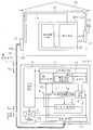
자동차(1)의 배터리(6)와 가옥(16)의 가정용 전력 공급기(19)의 충전용 연결은 충전 케이블(18)을 사용하는 전선에 제한되지 않는다. 예를 들어, 도 2를 참조하면, 상기 충전용 연결은 1차 코일(38)과 2차 코일(39)을 이용한 자동차(1)와 가정용 전력 공급기(19)의 자기적 연결을 위한 자기적 배선일 수 있다. 즉, 옥외 콘센트(17)에 연결된 1차 코일(38)은 지면에 매장되고, 2차 코일(39)은 자동차(1) 내에 배치된다. 2차 코일(39)은 2차 코일(39)에 의해 유도된 전류가 배터리(6)에 흐를 수 있도록 배터리(6)에 연결된다.The charging connection of the
배터리(6)를 충전할 때, 사용자는 자동차(1)의 2차 코일(39)이 1차 코일(38)을 향하도록 자동차(1)를 주차한다. 1차 코일(38)은 이 상태에서 옥외 콘센트(17)에 연결되어 1차 코일(38)에 전류가 흐를 수 있다. 이는 1차 코일(38)에 자속(magnetic flux)을 생성하고, 상기 자속은 2차 코일(39)에 인가되어, 2차 코일(39)에서 전류가 유도된다. 결과적으로, 배터리(6)는 2차 코일(39)에 흐르는 전류에 의하여 충전된다. 이 경우, 인증이 수행될 때, 충전 전류의 주파수보다 상당히 높은 주파수의 전류 변동을 통한 통신을 수행하도록 데이터 통신 중 교환되는 송수신 신호들의 주파수들은 충전 전류의 주파수보다 상당히 높은 주파수로 설정될 수 있다.When charging the
이하, 제 1 실시예에 따른 충전 시스템의 장점을 설명한다.Hereinafter, the advantages of the charging system according to the first embodiment will be described.
[1] 전기 자동차와 같은 자동차(1)를 계속적으로 사용하기 위해서는 배터리(6)가 정기적으로 충전되어야만 한다. 그러므로, 훔친 자동차(1)를 계속해서 운전하기 위해서는, 배터리(6)를 충전하기 위하여 가옥(16)에서 ID 박스(22) 또한 반드시 도둑질해야만 한다. 그러나, 가옥(16)에서 ID 박스(22)를 훔치는 것은 어려운 일이다. 이는 자동차를 훔치는 도둑의 동기를 감소시키고 자동차 도난 방지 가능성을 증가시킨다. 충전 제어 ECU(11)와 ID 박스(22)를 연결하는 충전 케이블(18) 및 실내 전력선(20)은 데이터 통신 경로로서 사용된다. 따라서, 무선 통신의 관심사인 무선 잡음 영향 등과 같은 문제를 고려할 필요가 없다. 그러므로, 충전 제어 ECU(11)가 ID 박스(22)와 인증을 수행할 때 통신이 방해받는 상황은 거의 발생하지 않고, 인증의 신뢰도가 보장된다.[1] In order to continuously use a vehicle 1 such as an electric vehicle, the
[2] 충전 제어 ECU(11)와 ID 박스(22) 사이의 데이터 통신으로서 전력선 통신이 수행된다. 그래서, 충전 케이블(18) 및 실내 전력선(20)은 전력 시스템 배선과 동시에 제어 시스템 배선으로 작용한다. 이에 따라, 충전 제어 ECU(11)와 ID 박스(22) 사이의 인증이 수행될 때 데이터 통신 경로를 제공하는 제어 시스템 배선이 새로 추가될 필요가 없고, 구성요소들의 수가 증가될 필요가 없다.[2] Power line communication is performed as data communication between the
[3] 충전 제어 ECU(11)와 ID 박스(22) 사이의 인증을 위하여 암호들(codes)이 사용된다. 이는 충전 허가 여부를 결정할 때 인증 신뢰도를 증가시킨다. 그러므 로, 충전 제어 ECU(11)와 ID 박스(22) 사이에 불법적인 방법으로 인증이 확립되는 상황이 거의 발생하지 않는다. 이는 인증되지 않은 충전의 방지에 효율적이다.[3] Codes are used for authentication between the
[4] 가정용 전력 공급기(19)로 자동차(1)의 배터리를 충전할 때 충전 케이블(18)을 사용하는 유선 시스템이 채용된다. 그래서, 배터리(6)는 상대적으로 저렴한 종래 시스템을 사용하여 충전될 수 있다.[4] A wired system using the charging
[5] 충전 시스템은, 옥외 콘센트(17)로부터 연장된 실내 전력선(20)이 ID 박스(22)를 통하지 않고 실내 콘센트(21)에 직접적으로 연결되는 직접적 방법을 채용한다. 게다가, ID 박스(22)는 독립적인 구성요소이다. 그러므로, 가정에 ID 박스(22)를 설치할 때 ID 박스(22)로부터 연장된 연결 코드(23)를 실내 콘센트(21)에 연결하는 오직 하나의 동작만이 요구된다. 이는 연결을 용이하게 한다.[5] The charging system adopts a direct method in which the
[6] 배터리(6)는 1차 코일(38) 및 2차 코일(39)로 자기적 배선을 통하여 충전될 수 있다. 이 경우, 배터리(6)를 충전할 때, 충전 시스템 케이블 구성요소로 자동차(1)가 가정용 전력 공급기(6)에 연결될 필요가 없다. 그래서, 배터리(6)는 용이하게 충전될 수 있다.The
[제 2 실시예]Second Embodiment
이하, 도 3을 참조하여 본 발명의 제 2 실시예에 따른 충전 시스템을 설명한다. 본 발명의 제 2 실시예에서는 ID 박스(22)에 대한 실내 전력선(20)의 연결이 제 1 실시예와 다르다. 동일한 참조 번호는 제 1 실시예의 구성요소와 동일한 구성요소를 나타내고, 동일한 구성요소에 대한 상세한 설명은 생략한다.Hereinafter, a charging system according to a second embodiment of the present invention will be described with reference to FIG. 3. In the second embodiment of the present invention, the connection of the
도 3을 참조하면, 제 2 실시예에 따른 충전 시스템은 실내 전력선(20)이 제 2 실시예에서 채용된 ID 박스(22)를 통하여 가정용 전력 공급기(19)에 연결되는 분할 방법을 사용한다. 제 1 실시예에 따른 도 1의 ID 박스(22)의 구성요소들에 더하여, 제 2 실시예에 따른 ID 박스(22)는 입력 신호의 저주파 성분을 제거하는 저역 통과 필터(LPF, 40)를 더 포함한다. 저역 통과 필터(40)는 ID 박스(22)의 전력선 결합 회로(31)에 연결되고, 연결 코드(23)에 의하여 ID 박스(22) 외부의 실내 콘센트(21)에 연결된다. 저역 통과 필터(40)는 가정용 전력 공급기(19)의 출력으로부터 실내 전력선(20)에 고주파 성분이 중첩되는 것을 방지하도록 배치된다.Referring to FIG. 3, the charging system according to the second embodiment uses a split method in which the
외부 전력선 시스템 배선에 연결 가능한 커넥터(41)가 ID 박스(22)에 배치된다. 커넥터(41)는 ID 박스(22)의 전력선 연결 회로(31) 및 저역 통과 필터(40)에 전기적으로 연결된다. ID 박스(22)는 실내 콘센트(21)에 연결된 연결 코드(23)를 통하여 가정용 전력 공급기(19)로부터 전력을 제공받는다. 그래서, 실내 전력선(20)이 ID 박스(22)의 커넥터(41)에 연결된 때, 가정용 전력 공급기(19)에서 실내 전력선(20)으로 전류가 흐른다.The
자동차(1)의 충전 커넥터(15)에 연결된 충전 케이블(18)을 통하여 배터리(6)에 전류가 흐르는 것이 감지될 때, 충전 제어 ECU(11)는 충전 케이블(18) 및 실내 전력선(20)을 이용한 전력선 통신을 통하여 ID 박스(22)에 ID 박스 활성화 신호(Swk)를 송신한다. 커넥터(41)를 통하여 수신된 ID 박스 활성화 신호(Swk)에 응답하여, ID 박스가 활성화된다. ID 박스 활성화 신호(Swk)의 전송 및 충전 제어 ECU(11)와 ID 박스(22) 사이의 인증처리는 제 1 실시예에서와 같은 방법으로 수행 된다. 따라서, 이에 대한 자세한 설명은 생략한다. 가정용 전력 공급기(19)에서 실내 전력선(20)으로 ID 박스(22)의 저역 통과 필터(40)를 통하여 전류가 흐른다. 그러면, 충전 케이블(18)을 통하여 자동차(1)의 배터리(6)로 전류가 흐른다.When it is detected that current flows in the
또한, 상기 분할 방법을 사용하는 본 발명의 제 2 실시예에 따른 충전 시스템은 충전 케이블(18)을 ID 박스(22)의 커넥터(41)에 직접 연결함으로써 자동차(1)의 배터리(6)를 충전할 수 있다. 그래서, 옥외 콘센트(17)가 근처에 위치하지 않더라도 충전 케이블(18)을 ID 박스(22)에 연결함으로써 ID 박스가 가까이에 있으면 배터리(6)가 충전될 수 있다.Further, the charging system according to the second embodiment of the present invention using the division method connects the
본 발명의 제 2 실시예에 따른 충전 시스템은 본 발명의 제 1 실시예의 장점들 [1], [2], [3], [4] 및 [6]에 더하여 아래의 장점을 가진다.The charging system according to the second embodiment of the present invention has the following advantages in addition to the advantages [1], [2], [3], [4] and [6] of the first embodiment of the present invention.
[7] 상기 분할 방법을 사용하는 충전 시스템에서, 배터리(6)를 충전할 때 옥외 콘센트(17)가 근처에 위치하지 않더라도 충전 케이블(18)을 ID 박스(22)의 커넥터(41)에 연결함으로써 배터리(6)를 가정용 전력 공급기(19)에 연결할 수 있다. 그러므로, 배터리(6)는 실내 콘센트(17)가 근처에 없더라도 충전될 수 있다.[7] In the charging system using the above division method, when charging the
[제 3 실시예][Third Embodiment]
이하, 도 4를 참조하여 본 발명의 제 3 실시예에 따른 충전 시스템을 설명한다. 제 3 실시예는 충전 제어 ECU(11)와 ID 박스(22) 사이의 통신 방법이 제 1 실시예와 다른 통신 방법을 가진다. 동일한 참조 번호는 제 1 실시예의 구성요소와 동일한 구성요소를 나타내고, 동일한 구성요소에 대한 상세한 설명은 생략한다.Hereinafter, a charging system according to a third embodiment of the present invention will be described with reference to FIG. 4. The third embodiment has a communication method in which the communication method between the
본 발명의 제 3 실시예에서, 전력선을 통한 통신 대신에, 데이터 통신 전용의 제어 시스템 배선을 사용하여 충전 제어 ECU(11)와 ID 박스(22) 사이의 통신이 수행된다. 상기 제어 시스템 배선을 통하여 데이터 통신 처리를 실행하는 마이크로컴퓨터(42)가 ID 박스(22)에 배치된다. 마이크로컴퓨터(42)와의 데이터 통신을 하는 동안 출력 데이터의 변조, 입력 데이터의 복조와 같은 다양한 처리들을 수행하는 통신 회로(43)가 마이크로컴퓨터(42)에 연결된다.In the third embodiment of the present invention, instead of the communication via the power line, communication between the
데이터 통신 경로로 작용하는 실내 제어선(44)의 일단이 ID 박스(22)의 통신 회로(43)에 연결된다. 실내 제어선(44)의 타단은 옥외 콘센트(17)에 연결된다. 즉, 실내 제어선(44)은 ID 박스(22)를 옥외 콘센트(17)에 연결한다. 제 3 실시예의 옥외 콘센트(17)는 실내 전력선(20)을 통하여 전류를 전송하는 것에 더하여 실내 제어선(44)을 통하여 데이터 전송을 가능하게 하는 접속 구성요소이다. 실내 제어선(44)은 전기적 배선을 형성한다.One end of the
충전 케이블(18)은, 가정용 전력 공급기(19)로부터 흐르는 전류를 위한 전류 경로로서 작용하는 전력선(18a), 및 충전 케이블 ECU(11)와 ID 박스(22) 사이의 데이터 통신 경로로서 작용하는 제어선(18b)을 포함한다. 충전 케이블(18)은 탄소(carbon)와 같은 코팅 물질로 전력선(18a) 및 제어선(18b)을 덮은 하나의 케이블 구성요소이다. 충전 케이블(18)이 충전 커넥터(15)에 연결된 경우, 충전 케이블(18)의 제어선(18b)이 자동차(1)에서 충전 커넥터(15)와 충전 제어 ECU(11)를 연결하는 통신선(45)을 통하여 충전 제어 ECU(11)에 연결된다. 전력선(18a)은 전력이 전송되는 라인을 형성하고, 제어선(18b)는 전기적 배선을 형성한다.The charging
충전 제어 ECU(11)는 실내 제어선(44), 제어선(18b) 및 통신선(45)을 통하여 대기 상태의 ID 박스(22)로부터 충전 케이블(18)과 충전 커넥터(15) 사이의 연결에 대한 통지를 받는다. 상기 연결 통지에 응답하여, 충전 제어 ECU(11)는 ID 박스(22)를 활성화시키기 위하여 통신선(45), 제어선(18b) 및 실내 제어선(44)을 통하여 ID 박스(22)에 ID 박스 활성화 신호(Swk)를 송신한다. 마이크로컴퓨터(24)는 통신 회로(43)를 통하여 충전 제어 ECU(11)로부터 ID 박스 활성화 신호(Swk)를 수신하고, 이에 대한 응답으로 ID 박스(22)를 활성화하기 시작한다.The charging
ID 박스(22)의 활성화 완료를 인식한 후, 마이크로컴퓨터(42)는 실내 제어선(44), 제어선(18b) 및 통신선(45)을 통하여 충전 제어 ECU(11)에 활성화 완료 신호(Sok)를 송신한다. 충전 제어 ECU(11)는 실내 제어선(44), 제어선(18b) 및 통신선(45)을 통하여 ID 박스(22)의 인증을 수행한다. 이 경우, 실내 전력선(20) 및 전력선(18a)을 통하여 가정용 전력 공급기(19)에서 자동차(1)의 배터리(6)로 전류가 흐른다. 충전 제어 ECU(11)는, 충전 케이블(18)이 충전 커넥터(45)로부터 제거되고 제어선(18b)으로부터 더 이상 신호가 수신되지 않을 때, 스위치(14)를 활성화 상태로 복구한다.After recognizing the activation completion of the
상기 전력선은 원래 고주파 신호 전송을 위하여 고안되지는 않았다. 그래서, 상기 전력선을 전력선 통신에 사용하면, 전력선으로부터 전파가 누설되고, 전파의 주파수가 단파 대역에 중첩될 수 있다. 이는 단파 통신과 아마추어 무선 통신에 악영향을 끼칠 수 있다. 그러나, 제 3 실시예에서는 충전 제어 ECU(11)와 ID 박스(22) 사이의 데이터 통신을 위하여 데이터 통신 제어선들(18b 및 44)이 사용되므 로, 전력선 통신을 수행할 때 발생하는 다양한 문제들에 대하여 걱정할 필요가 없다.The power line was not originally designed for high frequency signal transmission. Thus, when the power line is used for power line communication, radio waves may leak from the power line, and the frequency of the radio waves may overlap the short wave band. This can adversely affect shortwave communication and amateur radio communication. However, in the third embodiment, since the data
본 발명의 제 3 실시예에 따른 충전 시스템은 본 발명의 제 1 실시예의 장점들 [1], [3], [4], [5] 및 [6]에 더하여 아래의 장점을 가진다.The charging system according to the third embodiment of the present invention has the following advantages in addition to the advantages [1], [3], [4], [5] and [6] of the first embodiment of the present invention.
[8] 제어선들(18b, 44)이 충전 제어 ECU(11)와 ID 박스(22) 사이의 데이터 통신 경로 전용으로 사용된다. 그래서, 전력선 통신이 수행될 때 발생할 수 있는 전파의 누설을 걱정할 필요가 없고, 주위의 단파 통신 및 아마추어 무선 통신에 악영향을 끼치는 상황을 피할 수 있다. 충전 제어 ECU(11)와 ID 박스(22) 사이의 데이터 통신 경로를 위한 제어선들(18b, 44)의 전용은 상기 직접 방법 및 상기 분할 방법 중 어느 것을 채용한 충전 시스템에도 적용 가능하다.[8]
[제 4 실시예][Fourth Embodiment]
이하, 도 5를 참조하여 본 발명의 제 4 실시예에 따른 충전 시스템을 설명한다. 제 4 실시예에서는 제 1 실시예에서 설명된 ID 박스(22)와 다른 구조를 가진 ID 박스가 개시된다. 동일한 참조 번호는 제 1 실시예의 구성요소와 동일한 구성요소를 나타내고, 동일한 구성요소에 대한 상세한 설명은 생략한다.Hereinafter, a charging system according to a fourth embodiment of the present invention will be described with reference to FIG. 5. In the fourth embodiment, an ID box having a structure different from that of the
도 1에 도시된 것과 같은 단일 독립 인증 장치를 구성하는 ID 박스(22)와는 달리, 제 4 실시예에 따른 ID 박스 시스템 장치는, 도 5에 도시된 것과 같이, 자동차 키(46) 및 자동차 키(46)가 삽입될 수 있는 통신 박스(47)를 포함한다. 도 1의 마이크로컴퓨터(24)는 자동차 키(46)에 통합되고, 상기 키(47)에 대한 고유 암호키 가 마이크로컴퓨터(24)에 기록된다. 일반 기계적 키에 더하여, 자동차 키(46)는 기록된 ID 암호(code)를 자동차(1)가 활성화된 때 무선 통신을 통하여 자동차(1)에 송신하는 전자적 키일 수 있다. 자동차 키(46)가 전자적 키인 경우, 무선 통신 장치(wireless communication mechanism)가 마이크로컴퓨터(24)에 통합될 수 있다.Unlike the
도 5에 도시된 것과 같이, 통신 박스(47)는 자동차 키(46)를 위한 소켓으로 작용하는 슬롯(47a)을 포함한다. 자동차 키(46)가 슬롯(47a)에 완전히 삽입될 때, 마이크로컴퓨터(24)는 데이터 통신이 가능한 방법으로 통신 박스(47)의 가정용 전력선 통신 모듈(26)의 아날로그 프론트 엔드(27)에 연결된다. 상술한 바와 같이, 데이터 통신은 유선 또는 무선 통신을 통하여 수행될 수 있다. 통신 박스(47)가 ID 박스 시스템 장치로서 사용되면, 배터리(6) 충전 허가 여부를 결정하기 위한 인증 통신이 자동차 키(46)의 마이크로컴퓨터(24)와 충전 제어 ECU(11) 사이에서 수행된다. 자동차 키(46) 및 통신 박스(47)는 인증 관리 장치를 구성한다.As shown in FIG. 5, the
가정용 전력 공급기(19)로 배터리(6)를 충전할 때, 충전 케이블(18)이 옥외 콘센트(17)에 연결되고, 자동차(1)의 충전 커넥터(15)에 연결된다. 그리고, 조작자가 가옥(16)으로 들어가서 그 또는 그녀의 자동차 키를 실내 콘센트(21)에 연결된 통신 박스(47)의 슬롯(47a)에 삽입한다. 자동차 키(46)가 슬롯(47a)에 완전히 삽입되면, 자동차 키(46)안의 마이크로컴퓨터(24)는 통신 박스(47)의 가정용 전력선 통신 모듈(26)에 전기적으로 연결된다. 이는 가정용 전력선 통신 모듈(26)의 활성화를 시작하게 한다.When charging the
마이크로컴퓨터(24)를 포함한 가정용 전력선 통신 모듈(26)의 활성화 완료를 인식한 후, 마이크로컴퓨터(24)는 전력선 통신 (또는 제어선 통신)을 통하여 충전 제어 ECU(11)에 활성화 완료 신호(Sok)를 송신한다. 충전 제어 ECU(11)는 활성화 완료 신호(Sok)에 응답하여 자동차 키(46)가 진정한지 여부를 확인한다. 제 1 실시예의 인증 절차와 동일한 인증 절차가 사용되고, 따라서 이에 대한 자세한 설명은 생략한다.After recognizing the activation completion of the home power
본 발명의 제 4 실시예에 따른 충전 시스템은 본 발명의 제 1 실시예의 장점들 [1] 내지 [6]에 더하여 아래의 장점을 가진다.The charging system according to the fourth embodiment of the present invention has the following advantages in addition to the advantages [1] to [6] of the first embodiment of the present invention.
[9] 자동차(1)를 훔치고 훔친 자동차의 배터리(6)를 충전하려는 도둑은, ID 박스(22) 외에 자동차 키(46)를 더 훔쳐야만 한다. 그러므로, 상기 훔친 자동차를 충전하기 위해서는, 상기 도둑은 ID 박스(22)와 자동차 키(46)의 두 구성요소를 모두 훔쳐야만 한다. 이는 도둑을 더 곤란하게 만든다. 게다가, 자동차의 주인은 보통 자동차 키(46)를 들고 다닌다. 그래서, 실제로 이 두 구성요소들을 모두 훔치는 것은 매우 어려운 일이다. 이것이 도둑이 자동차를 훔치는 동기를 감소시키고, 도난 방지 가능성을 상당히 향상시킬 수 있다.[9] A thief who steals the car 1 and charges the stolen car's
[제 5 실시예][Example 5]
이하, 도 6을 참조하여 본 발명의 제 5 실시예에 따른 충전 시스템을 설명한다. 제 5 실시예에서는 다른 구조를 가진 ID 박스 시스템 장치가 개시된다. 동일한 참조 번호는 제 1 실시예의 구성요소와 동일한 구성요소를 나타내고, 동일한 구성요소에 대한 자세한 설명은 생략한다.Hereinafter, a charging system according to a fifth embodiment of the present invention will be described with reference to FIG. 6. In the fifth embodiment, an ID box system apparatus having another structure is disclosed. The same reference numerals denote the same components as the components of the first embodiment, and detailed description of the same components is omitted.
도 1에 도시된 ID 박스(22) 및 도 5에 도시된 ID 박스 시스템 장치(자동차 키(46) 및 통신 박스(47))와는 달리, 제 5 실시예에 따른 ID 박스 시스템 장치는, 도 6에 도시된 것과 같이, 플러그가 추가된 자동차 키(48)를 포함한다. 자동차 키(48)는 도 1의 마이크로컴퓨터(24) 및 가정용 전력선 통신 모듈(26)을 통합한 키 몸체부(48a), 및 키 몸체부(48a)로부터 연장된 플러그(49)를 포함한다. 자동차(1)와 ID 암호 무선 통신(ID code wireless communication)을 수행하는 무선 통신 장치(50)가 키 몸체부(48a)에 통합된다. 플러그(49)는 가옥(16)의 실내 콘센트(21)에 연결가능하고, 사용하지 않을 때 키 몸체부(48a)로 들어갈 수 있다. 플러그가 추가된 자동차 키(48)는 인증 관리 장치를 구성한다.Unlike the
가정용 전력 공급기(19)로 배터리(6)를 충전할 때, 충전 케이블(18)이 옥외 콘센트(17)에 연결되고, 자동차(1)의 충전 커넥터(15)에 연결된다. 그 후, 조작자가 가옥(16)으로 들어가서 그 또는 그녀의 자동차 키(48)로부터 플러그(49)를 뽑아 실내 콘센트(21)에 연결한다.When charging the
실내 콘센트(21)에 연결된 플러그(49)를 통한 플러그가 추가된 자동차 키(48)의 전류 흐름을 감지할 때, 자동차 키(48) 내의 마이크로컴퓨터(24)가 활성화된다. 활성화 완료를 인식한 후, 마이크로컴퓨터(24)는 전력선 통신 (또는 제어선 통신)을 통하여 충전 제어 ECU(11)에 활성화 완료 신호(Sok)를 송신한다. 충전 제어 ECU(11)는 활성화 완료 신호(Sok)에 응답하여 자동차 키(46)가 진정한지 여부를 확인한다. 제 1 실시예의 인증 절차와 동일한 인증 절차가 사용되고, 따라서 이에 대한 자세한 설명은 생략한다.When detecting the current flow of the added
본 발명의 제 5 실시예에 따른 충전 시스템은 본 발명의 제 1 실시예의 장점들 [1] 내지 [6]에 더하여 아래의 장점을 가진다.The charging system according to the fifth embodiment of the present invention has the following advantages in addition to the advantages [1] to [6] of the first embodiment of the present invention.
[10] 도둑이 자동차(1)를 훔치더라도, 자동차 주인이 보통 가지고 다니는 자동차 키(48) 또한 훔치지 않으면 배터리(6)가 충전될 수 없다. 자동차 키(48)는 훔치기 힘들다. 이는 도둑이 자동차를 훔치는 동기를 감소시키고, 자동차(1)의 도난 방지 가능성을 보장할 수 있다. 도 1의 ID 박스(22)가 사용될 때, ID 박스(22)가 항상 실내 콘센트(21)에 연결되어 있을 수 있으므로, 대기 상태에서 에너지가 소모될 수 있다. 그러나, 제 5 실시예에서는, 플러그(49)가 사용 중에만 옥외 콘센트(17)에 연결될 수 있다. 그래서, 대기 에너지가 소모되지 않고, 가정용 전력 공급기(19)의 전력 소비를 효율적으로 감소시킬 수 있다.[10] Even if a thief steals a car 1, the
상기 실시예들은 아래와 같이 수정될 수 있다.The above embodiments can be modified as follows.
제 1 내지 제 5 실시예들에서, 충전 허가 여부를 결정할 때 수행되는 인증은 시도-응답 방법에 반드시 한정되는 것은 아니다. 충전 제어 ECU(11)와 ID 박스(22) 각각에 고유 ID 암호(unique ID code)가 부여될 수 있으며, ID 검증이 상기 암호들의 매치 여부를 결정함으로써 수행될 수 있다. 상기 ID 검증은 충전을 수행할 때 지문을 수집하고 ID 박스(22)에 기록된 지문 데이터와 수집된 지문을 비교하는 생물 측정학적 인증(biometrics authentication)일 수 있다.In the first to fifth embodiments, the authentication performed when determining whether to charge is not necessarily limited to the challenge-response method. A unique ID code may be assigned to each of the
제 1 내지 제 5 실시예들에서, 시도-응답 방법에서와 같이 암호들(codes)을 사용하여 인증이 수행될 때, 암호키(code key)가 공개키(public key)가 아닌 비밀키(private key)일 수 있다.In the first to fifth embodiments, when authentication is performed using codes as in the challenge-response method, the code key is not a public key but a private key. key).
제 1 내지 제 5 실시예들에서, 충전 제어 ECU(11)와 ID 박스(22) 사이의 데이터 통신을 위하여 암호화 통신(encryption communication)이 사용될 수 있다. 이러한 경우에 사용되는 암호들은 DES(Data Encryption Standard), AES(Advanced Encryption Standard), RC(Rivest Code) 등을 따르는 비밀키 암호, Diffie-Hellman법, RSA, ElGmmal법 등을 따르는 공개키 암호, 또는 비밀키 및 공개키를 조합한 하이브리드 암호(hybrid code)일 수 있다.In the first to fifth embodiments, encryption communication can be used for data communication between the
제 1 내지 제 5 실시예들에서, ID 박스 시스템 장치는 가정용 전력 공급기(19)에 연결될 때 그것에 자동적으로 전류가 흐르는 구조에 반드시 한정되지는 않는다. 예를 들어, 가정용 전력 공급기(19)에 연결된 상태에서 전력 공급 스위치가 켜질 때 가정용 전력 공급기(19)에서 장치 몸체부로 전력이 공급되도록, ID 박스 시스템 장치의 장치 몸체부에 전력 공급 스위치가 배치될 수 있다.In the first to fifth embodiments, the ID box system apparatus is not necessarily limited to a structure in which current flows automatically when connected to the
제 3 실시예에서, 전력선(18a) 및 제어선(18b)은 반드시 동일한 케이블(18)에 포함되어야만 하는 것은 아니고, 각각 다른 배선들에 포함될 수 있다.In the third embodiment, the
제 1 내지 제 5 실시예들에서, 자동차(1)는 전기 자동차에 반드시 한정되는 것은 아니고, 구동원으로서 모터 및 엔진을 모두 사용하는 하이브리드 자동차(hybrid vehicle)일 수 있다. 충전 대상은 자동차에 한정되지 않고, 구동원으로서 제공되는 배터리(6)로 동작하는 기구(apparatus) 또는 장치(device)일 수 있다.In the first to fifth embodiments, the motor vehicle 1 is not necessarily limited to an electric vehicle, but may be a hybrid vehicle using both a motor and an engine as a driving source. The object to be charged is not limited to an automobile, but may be an apparatus or a device that operates with a
Claims (12)
Translated fromKoreanApplications Claiming Priority (2)
| Application Number | Priority Date | Filing Date | Title |
|---|---|---|---|
| JP2006236912AJP4366385B2 (en) | 2006-08-31 | 2006-08-31 | Charging system |
| JPJP-P-2006-00236912 | 2006-08-31 |
Publications (2)
| Publication Number | Publication Date |
|---|---|
| KR20080034167A KR20080034167A (en) | 2008-04-18 |
| KR100960682B1true KR100960682B1 (en) | 2010-05-31 |
Family
ID=39135677
Family Applications (1)
| Application Number | Title | Priority Date | Filing Date |
|---|---|---|---|
| KR1020087004526AExpired - Fee RelatedKR100960682B1 (en) | 2006-08-31 | 2007-07-11 | Charging system |
Country Status (6)
| Country | Link |
|---|---|
| US (1) | US8525473B2 (en) |
| EP (1) | EP2058916B1 (en) |
| JP (1) | JP4366385B2 (en) |
| KR (1) | KR100960682B1 (en) |
| CN (1) | CN101356705A (en) |
| WO (1) | WO2008026390A1 (en) |
Families Citing this family (107)
| Publication number | Priority date | Publication date | Assignee | Title |
|---|---|---|---|---|
| US9466419B2 (en)* | 2007-05-10 | 2016-10-11 | Auckland Uniservices Limited | Apparatus and system for charging a battery |
| JP2009027781A (en) | 2007-07-17 | 2009-02-05 | Seiko Epson Corp | Power reception controller, power receiver, contactless power transmitting system, charge controller, battery device, and electronic equipment |
| US20090070882A1 (en)* | 2007-09-10 | 2009-03-12 | Frank Grass | Method for transmitting user data between subscribers and subscriber devices therefor |
| JP4840337B2 (en)* | 2007-11-23 | 2011-12-21 | 株式会社デンソー | Water heater, door phone and vehicle charging device |
| US9264231B2 (en) | 2008-01-24 | 2016-02-16 | Intermec Ip Corp. | System and method of using RFID tag proximity to grant security access to a computer |
| US8072182B2 (en)* | 2008-01-25 | 2011-12-06 | Vasilantone Michael M | Hybrid automotive vehicle with closed-circuit, inductance battery charging |
| JP5194964B2 (en)* | 2008-04-07 | 2013-05-08 | 日本電気株式会社 | Electric vehicle battery charging system |
| JP2009296824A (en) | 2008-06-06 | 2009-12-17 | Toyota Industries Corp | Charging system |
| JP5305504B2 (en)* | 2008-07-04 | 2013-10-02 | 矢崎総業株式会社 | Charge monitoring device |
| JP5305505B2 (en)* | 2008-07-04 | 2013-10-02 | 矢崎総業株式会社 | Charge monitoring device |
| US8269452B2 (en)* | 2008-07-04 | 2012-09-18 | Yazaki Corporation | Battery charge monitoring device |
| US20110213983A1 (en)* | 2008-07-21 | 2011-09-01 | Paul Staugaitis | Authentication system for a plug-in electric drive vehicle |
| WO2010022059A1 (en) | 2008-08-18 | 2010-02-25 | Austin Christopher B | Vehicular battery charger, charging system, and method |
| EP2159731A1 (en) | 2008-08-26 | 2010-03-03 | Research In Motion Limited | Authorization status for smart battery used in mobile communication device |
| DE102008044527A1 (en)* | 2008-09-16 | 2010-03-25 | EnBW Energie Baden-Württemberg AG | Mobile electricity meter for location-independent electricity purchase and / or for location-independent power supply of a mobile storage and consumption unit |
| JP4438887B1 (en) | 2008-09-26 | 2010-03-24 | トヨタ自動車株式会社 | Electric vehicle and charging control method for electric vehicle |
| JP5268549B2 (en)* | 2008-10-07 | 2013-08-21 | トヨタ自動車株式会社 | Building security system |
| DE102008042677A1 (en)* | 2008-10-08 | 2010-04-15 | Robert Bosch Gmbh | Electric vehicle power supply system and method of controlling the same |
| WO2010059884A1 (en)* | 2008-11-21 | 2010-05-27 | Access Business Group International Llc | Inductive toy vehicle |
| US8258743B2 (en)* | 2008-12-05 | 2012-09-04 | Lava Four, Llc | Sub-network load management for use in recharging vehicles equipped with electrically powered propulsion systems |
| JP5344895B2 (en)* | 2008-12-10 | 2013-11-20 | 矢崎総業株式会社 | Charge monitoring device |
| JP5270328B2 (en)* | 2008-12-24 | 2013-08-21 | 株式会社アルファ | Electric vehicle charging system |
| JP4781425B2 (en) | 2008-12-25 | 2011-09-28 | 本田技研工業株式会社 | Power supply system between vehicle and house |
| JP5290735B2 (en)* | 2008-12-26 | 2013-09-18 | 株式会社アルファ | Electric vehicle charging control device |
| JP5373408B2 (en)* | 2009-01-05 | 2013-12-18 | 株式会社アルファ | Electric vehicle charging system, electric vehicle charging device, electric vehicle charging outlet device, and electric vehicle charging cable |
| JP5427417B2 (en)* | 2009-01-09 | 2014-02-26 | 株式会社アルファ | Electric car charging cable |
| JP2010179694A (en)* | 2009-02-03 | 2010-08-19 | Denso Corp | Plug-in vehicle management system |
| JP2010182239A (en) | 2009-02-09 | 2010-08-19 | Denso Corp | Plug-in vehicle management system |
| JP5379534B2 (en)* | 2009-03-27 | 2013-12-25 | 株式会社日本総合研究所 | Power supply apparatus and method |
| JP4950246B2 (en) | 2009-04-27 | 2012-06-13 | 三菱電機株式会社 | Vehicle charging system |
| DE102009020504B4 (en)* | 2009-05-08 | 2023-08-17 | Sew-Eurodrive Gmbh & Co Kg | Loading arrangement for a vehicle and vehicle |
| GB0908512D0 (en)* | 2009-05-18 | 2009-06-24 | Liberty Electric Cars Ltd | Charging plug for electric vehicles |
| NL1037029C2 (en)* | 2009-06-10 | 2010-12-13 | Cooperatieve Vereniging Easy Measure U A | METHOD AND DEVICE FOR WIRELESS CHARGING OF ELECTRIC VEHICLES. |
| DE102009030092A1 (en)* | 2009-06-22 | 2010-12-30 | Rwe Ag | Charging cable plug for electric vehicles |
| JP2011030404A (en)* | 2009-06-22 | 2011-02-10 | Felica Networks Inc | Information processing apparatus, program, and information processing system |
| JP5347773B2 (en)* | 2009-07-02 | 2013-11-20 | トヨタ自動車株式会社 | Vehicle charging cable |
| JP5226625B2 (en)* | 2009-07-27 | 2013-07-03 | カヤバ工業株式会社 | Vehicle anti-theft system |
| CN101969211B (en)* | 2009-07-28 | 2013-02-27 | 北汽福田汽车股份有限公司 | Charge protective device for electric vehicle and vehicle with same |
| US8946924B2 (en)* | 2009-07-30 | 2015-02-03 | Lutron Electronics Co., Inc. | Load control system that operates in an energy-savings mode when an electric vehicle charger is charging a vehicle |
| JP2012151519A (en) | 2009-07-31 | 2012-08-09 | Panasonic Corp | On-vehicle charger and vehicle using it |
| JP2012151914A (en) | 2009-07-31 | 2012-08-09 | Panasonic Corp | On-vehicle power line communication apparatus and vehicle using the same |
| JP2011120359A (en) | 2009-12-02 | 2011-06-16 | Toyota Motor Corp | Power supply device, vehicle, and charging system |
| JP5476973B2 (en)* | 2009-12-17 | 2014-04-23 | 株式会社デンソー | Vehicle charging system |
| JP5526833B2 (en) | 2010-02-05 | 2014-06-18 | ソニー株式会社 | Wireless power transmission device |
| JP5319573B2 (en)* | 2010-02-23 | 2013-10-16 | 株式会社東海理化電機製作所 | Outlet unauthorized connection prevention device and outlet unit |
| ES2346283B1 (en)* | 2010-03-03 | 2011-09-05 | Miguel Salamanques Claver | CONTROL SYSTEM AND MANAGEMENT OF ENERGY RECHARGE, COMMUNICATION AND LIGHTING. |
| US8405360B2 (en)* | 2010-04-07 | 2013-03-26 | Evp Technology Llc Usa | Energy-efficient fast charging device and method |
| KR101146873B1 (en)* | 2010-05-12 | 2012-05-16 | 주식회사 엘지씨엔에스 | Multi-channel metering system for electric chager and method of the same |
| US8841881B2 (en) | 2010-06-02 | 2014-09-23 | Bryan Marc Failing | Energy transfer with vehicles |
| DE102010041760A1 (en)* | 2010-06-30 | 2012-01-05 | Siemens Aktiengesellschaft | Charging device for charging energy storage and corresponding method |
| US8831077B2 (en)* | 2010-07-01 | 2014-09-09 | Texas Instruments Incorporated | Communication on a pilot wire |
| JP2012019636A (en)* | 2010-07-08 | 2012-01-26 | Denso Corp | Charging device for vehicle |
| JP5462095B2 (en)* | 2010-07-08 | 2014-04-02 | 株式会社東海理化電機製作所 | Charger |
| DE102010027640B4 (en)* | 2010-07-19 | 2023-10-05 | Sew-Eurodrive Gmbh & Co Kg | Electric charging system and method for contactless charging of a battery in a mobile unit |
| JP5556740B2 (en)* | 2010-10-28 | 2014-07-23 | Smk株式会社 | Information providing apparatus, information providing server, and vehicle support system |
| KR101233717B1 (en)* | 2010-12-08 | 2013-02-18 | 이점식 | Charging and charging system using smart connector |
| EP3981640A1 (en)* | 2011-02-17 | 2022-04-13 | Pioneer Corporation | Charging control apparatus and method, charging system, correlation method, and computer program |
| JP4831443B1 (en)* | 2011-02-25 | 2011-12-07 | 孝郎 林 | Power supply system with anti-theft function |
| JP5295292B2 (en)* | 2011-03-10 | 2013-09-18 | 三菱電機株式会社 | Battery charge / discharge system, energy management system, and electric vehicle |
| JP5750960B2 (en)* | 2011-03-18 | 2015-07-22 | ソニー株式会社 | Detection apparatus and detection method |
| JP5704399B2 (en)* | 2011-05-16 | 2015-04-22 | ソニー株式会社 | Power supply apparatus and method, and program |
| JP5392861B2 (en)* | 2011-05-16 | 2014-01-22 | ソニー株式会社 | Power supply apparatus and method, power supply system, and program |
| JP5741222B2 (en)* | 2011-05-31 | 2015-07-01 | ソニー株式会社 | Battery device, control method, and electric vehicle |
| US8686686B2 (en) | 2011-07-07 | 2014-04-01 | General Electric Company | System and method for use in charging an electrically powered vehicle |
| CN103688439B (en)* | 2011-07-14 | 2016-06-15 | 松下电器产业株式会社 | Charging unit and vehicle |
| US9531312B2 (en)* | 2011-09-26 | 2016-12-27 | Toyota Jidosha Kabushiki Kaisha | Vehicle and method of controlling vehicle |
| JP2013081323A (en)* | 2011-10-05 | 2013-05-02 | Mitsubishi Motors Corp | Power supply controller of power supply apparatus |
| US9419444B2 (en)* | 2011-10-05 | 2016-08-16 | Blackberry Limited | Wireless charging and communication with power source devices and power charge devices in a communication system |
| US8645481B2 (en) | 2011-10-05 | 2014-02-04 | Blackberry Limited | Wireless charging and communication with wireless communication devices in a communication system |
| EP2783897B1 (en)* | 2011-11-22 | 2019-05-15 | Toyota Jidosha Kabushiki Kaisha | Vehicle power reception device and vehicle equipped with the same, power supply apparatus, and electric power transmission system |
| KR101294533B1 (en) | 2011-12-23 | 2013-08-07 | 현대자동차주식회사 | System and method for sending/receiving data at charing EV |
| JP5829922B2 (en)* | 2012-01-10 | 2015-12-09 | トヨタ自動車株式会社 | On-vehicle charging device and vehicle charging system |
| US9270463B2 (en) | 2012-01-17 | 2016-02-23 | Panasonic Intellectual Property Management Co., Ltd. | Unauthorized connection detecting device, unauthorized connection detecting system, and unauthorized connection detecting method |
| CA2765945A1 (en) | 2012-01-30 | 2013-07-30 | Hydro-Quebec | Battery management system for an electric vehicle with energy loss detection |
| JP2013188020A (en)* | 2012-03-08 | 2013-09-19 | Takao Hayashi | Power supply system with power theft prevention function |
| EP2844515B1 (en)* | 2012-05-02 | 2016-12-07 | Jaguar Land Rover Limited | Vehicle security |
| KR101387226B1 (en)* | 2012-06-22 | 2014-04-21 | 엘에스산전 주식회사 | An electric vehicle charging system |
| JP5652442B2 (en)* | 2012-08-30 | 2015-01-14 | トヨタ自動車株式会社 | Power storage system and power storage device control device |
| KR101377570B1 (en) | 2012-09-25 | 2014-03-25 | 한국전력공사 | Apparatus and method for communication security for charging of electric vehicle |
| GB2508157A (en)* | 2012-11-21 | 2014-05-28 | Knightsbridge Portable Comm Sp | Induction charging with secure wireless communication |
| JP2014125095A (en)* | 2012-12-26 | 2014-07-07 | Tokai Rika Co Ltd | Vehicle anti-theft device |
| WO2014196933A1 (en)* | 2013-06-06 | 2014-12-11 | Nanyang Technological University | Battery charging devices, battery charging methods, battery systems, and methods for controlling batteries |
| US11349675B2 (en)* | 2013-10-18 | 2022-05-31 | Alcatel-Lucent Usa Inc. | Tamper-resistant and scalable mutual authentication for machine-to-machine devices |
| JP6361132B2 (en)* | 2013-12-24 | 2018-07-25 | トヨタ自動車株式会社 | Contactless power transfer system, charging station, and vehicle |
| DE102014201054A1 (en) | 2014-01-22 | 2015-07-23 | Robert Bosch Gmbh | Method and device for operating a battery, in particular a lithium ion battery, in a consumer |
| KR20150090325A (en)* | 2014-01-27 | 2015-08-06 | 한국전자통신연구원 | Electric vehicle, electric vehicle chanrging device and method for charging electric vehicle |
| JP6040950B2 (en)* | 2014-03-18 | 2016-12-07 | トヨタ自動車株式会社 | Hybrid vehicle and control method thereof |
| WO2015176246A1 (en)* | 2014-05-21 | 2015-11-26 | Intel Corporation | Wireless power transfer with improved device identification and signaling link security |
| WO2015196305A2 (en)* | 2014-06-26 | 2015-12-30 | Karle Innovation Ltd. | Power lock |
| DE102014011843B4 (en)* | 2014-08-08 | 2021-05-12 | Audi Ag | Charging connection device for a motor vehicle and motor vehicle with a charging connection device |
| CN105882437A (en)* | 2015-10-30 | 2016-08-24 | 乐卡汽车智能科技(北京)有限公司 | Vehicle charging method and system, and charging pile |
| CN106953374B (en)* | 2016-01-06 | 2019-11-05 | 松下知识产权经营株式会社 | The control method and server unit of server unit |
| WO2017173287A1 (en) | 2016-04-01 | 2017-10-05 | Lutron Electronics Co., Inc. | Wireless power supply for electrical devices |
| US11843597B2 (en)* | 2016-05-18 | 2023-12-12 | Vercrio, Inc. | Automated scalable identity-proofing and authentication process |
| US10148649B2 (en)* | 2016-05-18 | 2018-12-04 | Vercrio, Inc. | Automated scalable identity-proofing and authentication process |
| TWM575626U (en) | 2017-06-26 | 2019-03-11 | 美商米沃奇電子工具公司 | battery charger |
| DE102017118299A1 (en)* | 2017-08-11 | 2019-02-14 | Elektro-Bauelemente Gmbh | Charging station for electric vehicles with a safety clutch |
| JP2019092279A (en)* | 2017-11-14 | 2019-06-13 | トヨタ自動車株式会社 | Vehicle and power facility |
| DE102018208403A1 (en)* | 2018-05-28 | 2019-11-28 | Volkswagen Aktiengesellschaft | A method of configuring a permanently installed publicly accessible device, publicly accessible device for use in the method, configuration device for use in the method, and vehicle |
| KR102575725B1 (en)* | 2018-11-16 | 2023-09-07 | 현대자동차주식회사 | Apparatus, system and method for controlling charging of electric vehicle |
| US11303145B2 (en)* | 2018-12-11 | 2022-04-12 | Denso Corporation | Charging system |
| EP3831644B1 (en)* | 2019-02-12 | 2023-07-19 | Massimo Ferrari | Charging system and method of a battery of an electric vehicle |
| KR102548922B1 (en)* | 2019-02-15 | 2023-06-28 | 현대모비스 주식회사 | Electric vehicle charging system and method |
| CA3107827A1 (en)* | 2020-02-07 | 2021-08-07 | Bikef S.R.L. | Charging system and method of a battery of an electric vehicle |
| CN111526511B (en)* | 2020-05-15 | 2023-09-19 | 南京康尼机电股份有限公司 | Charging pile and charging vehicle identity verification method based on random code decoding |
| CN111682134B (en)* | 2020-05-30 | 2022-07-22 | 华为数字能源技术有限公司 | Anti-theft battery, battery module and cabinet |
| FI130937B1 (en)* | 2020-12-04 | 2024-06-07 | Liikennevirta Oy / Virta Ltd | An identification method for electric vehicle charging stations |
Citations (4)
| Publication number | Priority date | Publication date | Assignee | Title |
|---|---|---|---|---|
| JP2000050508A (en)* | 1998-07-27 | 2000-02-18 | Takayanagi Kenkyusho:Kk | Connector device for charger |
| JP2001078302A (en)* | 1999-09-07 | 2001-03-23 | Tokyo R & D Co Ltd | Motor-driven vehicle |
| JP2004147408A (en)* | 2002-10-23 | 2004-05-20 | Canon Inc | Electronic equipment system |
| JP2006164547A (en)* | 2004-12-02 | 2006-06-22 | Sony Corp | Battery pack, method of controlling charging and application apparatus |
Family Cites Families (22)
| Publication number | Priority date | Publication date | Assignee | Title |
|---|---|---|---|---|
| US3270267A (en)* | 1965-07-12 | 1966-08-30 | Elton Ind Inc | Battery charging device |
| US5323099A (en)* | 1992-01-22 | 1994-06-21 | Hughes Aircraft Company | Wall/ceiling mounted inductive charger |
| DE4236286A1 (en)* | 1992-10-28 | 1994-05-05 | Daimler Benz Ag | Method and arrangement for automatic contactless charging |
| JP2823491B2 (en)* | 1993-08-30 | 1998-11-11 | 株式会社東海理化電機製作所 | Vehicle anti-theft device |
| DE69533966T2 (en)* | 1994-11-11 | 2005-06-30 | Kabushiki Kaisha Tokai Rika Denki Seisakusho | METHOD FOR REGISTERING AN IDENTIFICATION CODE |
| GB9526235D0 (en) | 1995-12-21 | 1996-02-21 | British Tech Group | An electronic anti-theft method and related apparatus |
| JPH10262303A (en) | 1997-03-18 | 1998-09-29 | Honda Motor Co Ltd | Battery charger for motor vehicle using battery at least as part of its power |
| JPH11178234A (en)* | 1997-12-10 | 1999-07-02 | Nissan Motor Co Ltd | Home power supply system using electric vehicles |
| JP2000090348A (en)* | 1998-09-09 | 2000-03-31 | Honda Motor Co Ltd | Battery charging device and battery returning device |
| JP4691841B2 (en) | 2001-07-10 | 2011-06-01 | パナソニック株式会社 | Electric vehicle data communication system |
| US6614204B2 (en)* | 2001-12-21 | 2003-09-02 | Nicholas J. Pellegrino | Charging station for hybrid powered vehicles |
| JP2005012663A (en)* | 2003-06-20 | 2005-01-13 | Sanyo Electric Co Ltd | Authentication system and id generator |
| US6975092B2 (en)* | 2003-07-03 | 2005-12-13 | Dell Products L.P. | Encrypted response smart battery |
| JP2005151368A (en)* | 2003-11-19 | 2005-06-09 | Matsushita Electric Ind Co Ltd | Authentication system |
| US7498768B2 (en)* | 2004-02-04 | 2009-03-03 | Volkswagen Aktiengesellschaft | Key for a vehicle |
| US7613924B2 (en)* | 2005-03-08 | 2009-11-03 | Texas Instruments Incorporated | Encrypted and other keys in public and private battery memories |
| US7715884B2 (en)* | 2005-10-14 | 2010-05-11 | Research In Motion Limited | Mobile device with a smart battery having a battery information profile corresponding to a communication standard |
| WO2007041866A1 (en)* | 2005-10-14 | 2007-04-19 | Research In Motion Limited | Battery pack authentication for a mobile device |
| US7498766B2 (en)* | 2006-05-30 | 2009-03-03 | Symbol Technologies, Inc. | System and method for authenticating a battery |
| JP4366382B2 (en)* | 2006-08-02 | 2009-11-18 | 株式会社東海理化電機製作所 | Charging system |
| US7693609B2 (en)* | 2007-09-05 | 2010-04-06 | Consolidated Edison Company Of New York, Inc. | Hybrid vehicle recharging system and method of operation |
| US20090177595A1 (en)* | 2008-01-08 | 2009-07-09 | Stephen David Dunlap | Bidirectional metering and control of electric energy between the power grid and vehicle power systems |
- 2006
- 2006-08-31JPJP2006236912Apatent/JP4366385B2/enactiveActive
- 2007
- 2007-07-11USUS12/090,277patent/US8525473B2/enactiveActive
- 2007-07-11EPEP07790661.8Apatent/EP2058916B1/enactiveActive
- 2007-07-11WOPCT/JP2007/063857patent/WO2008026390A1/enactiveApplication Filing
- 2007-07-11CNCNA2007800011767Apatent/CN101356705A/enactivePending
- 2007-07-11KRKR1020087004526Apatent/KR100960682B1/ennot_activeExpired - Fee Related
Patent Citations (4)
| Publication number | Priority date | Publication date | Assignee | Title |
|---|---|---|---|---|
| JP2000050508A (en)* | 1998-07-27 | 2000-02-18 | Takayanagi Kenkyusho:Kk | Connector device for charger |
| JP2001078302A (en)* | 1999-09-07 | 2001-03-23 | Tokyo R & D Co Ltd | Motor-driven vehicle |
| JP2004147408A (en)* | 2002-10-23 | 2004-05-20 | Canon Inc | Electronic equipment system |
| JP2006164547A (en)* | 2004-12-02 | 2006-06-22 | Sony Corp | Battery pack, method of controlling charging and application apparatus |
Also Published As
| Publication number | Publication date |
|---|---|
| KR20080034167A (en) | 2008-04-18 |
| CN101356705A (en) | 2009-01-28 |
| JP2008061432A (en) | 2008-03-13 |
| EP2058916B1 (en) | 2013-09-11 |
| US8525473B2 (en) | 2013-09-03 |
| WO2008026390A1 (en) | 2008-03-06 |
| JP4366385B2 (en) | 2009-11-18 |
| EP2058916A1 (en) | 2009-05-13 |
| US20090278492A1 (en) | 2009-11-12 |
| EP2058916A4 (en) | 2011-12-28 |
Similar Documents
| Publication | Publication Date | Title |
|---|---|---|
| KR100960682B1 (en) | Charging system | |
| CN101496251B (en) | Charging system | |
| EP1602539B1 (en) | Vehicle security device and id code management device | |
| CN101400542B (en) | Vehicles and Electrical Equipment | |
| CN102804517B (en) | Charging cable plugs for electric vehicles | |
| JP4950246B2 (en) | Vehicle charging system | |
| JP4953147B1 (en) | Power supply system with anti-theft function | |
| JP4967865B2 (en) | Vehicle anti-theft device | |
| CN115053272A (en) | Improved electronic key | |
| JP2010208353A (en) | Control system for vehicle | |
| CN102029973B (en) | Automobile body controller with engine burglary-prevention function | |
| JP4831443B1 (en) | Power supply system with anti-theft function | |
| JP2010134566A (en) | System, method and program for supplying power for electric product | |
| KR101011148B1 (en) | Starting authentication system of heavy equipment vehicle using smart key and starting authentication method using same | |
| JP5462095B2 (en) | Charger | |
| JP5336639B1 (en) | Double authentication power supply system | |
| KR20050063287A (en) | System and method for preventing battery thief in hybrid automobile | |
| CN112820000A (en) | Identity authentication system and method for vehicle | |
| JP5290735B2 (en) | Electric vehicle charging control device | |
| JP2006120072A (en) | Cardless ETC in-vehicle device and in-vehicle system | |
| CN118850227A (en) | Two-wheeled vehicle and anti-theft method thereof | |
| JP2010042777A (en) | Antitheft device | |
| CN115056747A (en) | Pluggable vehicle-mounted control device, vehicle control system and vehicle control method | |
| TW200824949A (en) | Embedded type CDI burglarproof system realized by RFID | |
| JP2002021688A (en) | Automatic starting device for engine |
Legal Events
| Date | Code | Title | Description |
|---|---|---|---|
| A201 | Request for examination | ||
| PA0105 | International application | St.27 status event code:A-0-1-A10-A15-nap-PA0105 | |
| PA0201 | Request for examination | St.27 status event code:A-1-2-D10-D11-exm-PA0201 | |
| PG1501 | Laying open of application | St.27 status event code:A-1-1-Q10-Q12-nap-PG1501 | |
| R18-X000 | Changes to party contact information recorded | St.27 status event code:A-3-3-R10-R18-oth-X000 | |
| E902 | Notification of reason for refusal | ||
| PE0902 | Notice of grounds for rejection | St.27 status event code:A-1-2-D10-D21-exm-PE0902 | |
| P11-X000 | Amendment of application requested | St.27 status event code:A-2-2-P10-P11-nap-X000 | |
| P13-X000 | Application amended | St.27 status event code:A-2-2-P10-P13-nap-X000 | |
| E701 | Decision to grant or registration of patent right | ||
| PE0701 | Decision of registration | St.27 status event code:A-1-2-D10-D22-exm-PE0701 | |
| GRNT | Written decision to grant | ||
| PR0701 | Registration of establishment | St.27 status event code:A-2-4-F10-F11-exm-PR0701 | |
| PR1002 | Payment of registration fee | St.27 status event code:A-2-2-U10-U12-oth-PR1002 Fee payment year number:1 | |
| PG1601 | Publication of registration | St.27 status event code:A-4-4-Q10-Q13-nap-PG1601 | |
| FPAY | Annual fee payment | Payment date:20130503 Year of fee payment:4 | |
| PR1001 | Payment of annual fee | St.27 status event code:A-4-4-U10-U11-oth-PR1001 Fee payment year number:4 | |
| FPAY | Annual fee payment | Payment date:20140502 Year of fee payment:5 | |
| PR1001 | Payment of annual fee | St.27 status event code:A-4-4-U10-U11-oth-PR1001 Fee payment year number:5 | |
| FPAY | Annual fee payment | Payment date:20150416 Year of fee payment:6 | |
| PR1001 | Payment of annual fee | St.27 status event code:A-4-4-U10-U11-oth-PR1001 Fee payment year number:6 | |
| FPAY | Annual fee payment | Payment date:20160418 Year of fee payment:7 | |
| PR1001 | Payment of annual fee | St.27 status event code:A-4-4-U10-U11-oth-PR1001 Fee payment year number:7 | |
| FPAY | Annual fee payment | Payment date:20170421 Year of fee payment:8 | |
| PR1001 | Payment of annual fee | St.27 status event code:A-4-4-U10-U11-oth-PR1001 Fee payment year number:8 | |
| FPAY | Annual fee payment | Payment date:20180503 Year of fee payment:9 | |
| PR1001 | Payment of annual fee | St.27 status event code:A-4-4-U10-U11-oth-PR1001 Fee payment year number:9 | |
| P22-X000 | Classification modified | St.27 status event code:A-4-4-P10-P22-nap-X000 | |
| P22-X000 | Classification modified | St.27 status event code:A-4-4-P10-P22-nap-X000 | |
| PR1001 | Payment of annual fee | St.27 status event code:A-4-4-U10-U11-oth-PR1001 Fee payment year number:10 | |
| PC1903 | Unpaid annual fee | St.27 status event code:A-4-4-U10-U13-oth-PC1903 Not in force date:20200525 Payment event data comment text:Termination Category : DEFAULT_OF_REGISTRATION_FEE | |
| PC1903 | Unpaid annual fee | St.27 status event code:N-4-6-H10-H13-oth-PC1903 Ip right cessation event data comment text:Termination Category : DEFAULT_OF_REGISTRATION_FEE Not in force date:20200525 | |
| P22-X000 | Classification modified | St.27 status event code:A-4-4-P10-P22-nap-X000 |