KR100960662B1 - Led lighting apparatus - Google Patents
Led lighting apparatusDownload PDFInfo
- Publication number
- KR100960662B1 KR100960662B1KR1020090042976AKR20090042976AKR100960662B1KR 100960662 B1KR100960662 B1KR 100960662B1KR 1020090042976 AKR1020090042976 AKR 1020090042976AKR 20090042976 AKR20090042976 AKR 20090042976AKR 100960662 B1KR100960662 B1KR 100960662B1
- Authority
- KR
- South Korea
- Prior art keywords
- light source
- heat dissipation
- guide plate
- light guide
- substrate
- Prior art date
- Legal status (The legal status is an assumption and is not a legal conclusion. Google has not performed a legal analysis and makes no representation as to the accuracy of the status listed.)
- Expired - Fee Related
Links
Images


Classifications
- F—MECHANICAL ENGINEERING; LIGHTING; HEATING; WEAPONS; BLASTING
- F21—LIGHTING
- F21V—FUNCTIONAL FEATURES OR DETAILS OF LIGHTING DEVICES OR SYSTEMS THEREOF; STRUCTURAL COMBINATIONS OF LIGHTING DEVICES WITH OTHER ARTICLES, NOT OTHERWISE PROVIDED FOR
- F21V29/00—Protecting lighting devices from thermal damage; Cooling or heating arrangements specially adapted for lighting devices or systems
- F21V29/50—Cooling arrangements
- F21V29/70—Cooling arrangements characterised by passive heat-dissipating elements, e.g. heat-sinks
- F21V29/74—Cooling arrangements characterised by passive heat-dissipating elements, e.g. heat-sinks with fins or blades
- F—MECHANICAL ENGINEERING; LIGHTING; HEATING; WEAPONS; BLASTING
- F21—LIGHTING
- F21V—FUNCTIONAL FEATURES OR DETAILS OF LIGHTING DEVICES OR SYSTEMS THEREOF; STRUCTURAL COMBINATIONS OF LIGHTING DEVICES WITH OTHER ARTICLES, NOT OTHERWISE PROVIDED FOR
- F21V19/00—Fastening of light sources or lamp holders
- F21V19/001—Fastening of light sources or lamp holders the light sources being semiconductors devices, e.g. LEDs
- F21V19/003—Fastening of light source holders, e.g. of circuit boards or substrates holding light sources
- F21V19/0035—Fastening of light source holders, e.g. of circuit boards or substrates holding light sources the fastening means being capable of simultaneously attaching of an other part, e.g. a housing portion or an optical component
- F—MECHANICAL ENGINEERING; LIGHTING; HEATING; WEAPONS; BLASTING
- F21—LIGHTING
- F21V—FUNCTIONAL FEATURES OR DETAILS OF LIGHTING DEVICES OR SYSTEMS THEREOF; STRUCTURAL COMBINATIONS OF LIGHTING DEVICES WITH OTHER ARTICLES, NOT OTHERWISE PROVIDED FOR
- F21V19/00—Fastening of light sources or lamp holders
- F21V19/001—Fastening of light sources or lamp holders the light sources being semiconductors devices, e.g. LEDs
- F21V19/003—Fastening of light source holders, e.g. of circuit boards or substrates holding light sources
- F21V19/0045—Fastening of light source holders, e.g. of circuit boards or substrates holding light sources by tongue and groove connections, e.g. dovetail interlocking means fixed by sliding
- F—MECHANICAL ENGINEERING; LIGHTING; HEATING; WEAPONS; BLASTING
- F21—LIGHTING
- F21V—FUNCTIONAL FEATURES OR DETAILS OF LIGHTING DEVICES OR SYSTEMS THEREOF; STRUCTURAL COMBINATIONS OF LIGHTING DEVICES WITH OTHER ARTICLES, NOT OTHERWISE PROVIDED FOR
- F21V29/00—Protecting lighting devices from thermal damage; Cooling or heating arrangements specially adapted for lighting devices or systems
- F21V29/50—Cooling arrangements
- F21V29/502—Cooling arrangements characterised by the adaptation for cooling of specific components
- F21V29/503—Cooling arrangements characterised by the adaptation for cooling of specific components of light sources
- F—MECHANICAL ENGINEERING; LIGHTING; HEATING; WEAPONS; BLASTING
- F21—LIGHTING
- F21V—FUNCTIONAL FEATURES OR DETAILS OF LIGHTING DEVICES OR SYSTEMS THEREOF; STRUCTURAL COMBINATIONS OF LIGHTING DEVICES WITH OTHER ARTICLES, NOT OTHERWISE PROVIDED FOR
- F21V7/00—Reflectors for light sources
- F21V7/22—Reflectors for light sources characterised by materials, surface treatments or coatings, e.g. dichroic reflectors
- F—MECHANICAL ENGINEERING; LIGHTING; HEATING; WEAPONS; BLASTING
- F21—LIGHTING
- F21V—FUNCTIONAL FEATURES OR DETAILS OF LIGHTING DEVICES OR SYSTEMS THEREOF; STRUCTURAL COMBINATIONS OF LIGHTING DEVICES WITH OTHER ARTICLES, NOT OTHERWISE PROVIDED FOR
- F21V2200/00—Use of light guides, e.g. fibre optic devices, in lighting devices or systems
- F21V2200/20—Use of light guides, e.g. fibre optic devices, in lighting devices or systems of light guides of a generally planar shape
- F—MECHANICAL ENGINEERING; LIGHTING; HEATING; WEAPONS; BLASTING
- F21—LIGHTING
- F21Y—INDEXING SCHEME ASSOCIATED WITH SUBCLASSES F21K, F21L, F21S and F21V, RELATING TO THE FORM OR THE KIND OF THE LIGHT SOURCES OR OF THE COLOUR OF THE LIGHT EMITTED
- F21Y2115/00—Light-generating elements of semiconductor light sources
- F21Y2115/10—Light-emitting diodes [LED]
Landscapes
- Engineering & Computer Science (AREA)
- General Engineering & Computer Science (AREA)
- Planar Illumination Modules (AREA)
Abstract
Translated fromKoreanDescription
Translated fromKorean본 발명은 평판형 LED 조명장치에 관한 것으로서, 보다 상세하게는 평판형 LED 조명장치에 구성되는 광원부의 방열이 원활하게 이루어지도록 하여 광원의 열화를 방지하는 평판형 LED 조명장치용 방열장치에 관한 것이다.The present invention relates to a flat panel LED lighting device, and more particularly, to a heat sink for a flat panel LED lighting device to prevent the deterioration of the light source to facilitate the heat dissipation of the light source unit configured in the flat panel LED lighting device. .
일반적으로, 엘시디(LCD) 등의 백라이트유닛(Backlight Unit)으로 주로 사용되는 조명장치는 빛을 발광하는 광원이 투광 가능한 아크릴판으로 이루어지는 도광판의 일측에 설치되고, 상기 도광판은 광원의 빛의 경로 및 산란을 유도하기 위하여 일측 표면에 소정 패턴의 홈, 요철 돗트 또는 프린팅 돗트를 형성하여 구성된다.In general, a lighting device mainly used as a backlight unit such as an LCD is installed on one side of a light guide plate made of an acrylic plate that is capable of transmitting a light source that emits light. In order to induce scattering is formed by forming a predetermined pattern of grooves, uneven dots or printing dots on one surface.
도 1은 일반적인 백라이트 유닛으로 주로 사용되는 조명장치의 구성을 보인 후면도이고, 도 2는 도 1의 A-A선 단면 일부 상세도이다.1 is a rear view showing the configuration of a lighting device mainly used as a general backlight unit, Figure 2 is a partial cross-sectional view of the line A-A of FIG.
도 1 및 도 2에 도시된 바와 같이, 상기 종래의 조명장치(1)는 투광 가능한 재질 즉 아크릴판으로 형성된 도광판(10)의 측면에 빛을 발광하는 광원(40)이 설치되고, 상기 광원(40)은 이에 전기적으로 연결된 기판(미도시)을 수반하며, 상기 광원(40)과 기판을 포함하여 이하에서는 광원부(미도시)로 통칭한다.1 and 2, the
이러한 도광판(10)의 후면에는 측면의 광원(40)에서 발광된 빛을 전면으로 균일하게 산란시키기 위한 V홈(11)이 수평 및 수직방향으로 다수개 형성되고, 상기 V홈(11)이 형성된 도광판(10)의 후면에는 PET 재질 또는 종이 재질의 반사시트(20)가 부착되어 설치된다.On the rear surface of the
그리고, 상기 도광판(10)의 전면에는 빛을 전면으로 확산시켜 디스플레이하는 확산필름(30)이 부착되어 설치된다.In addition, the front of the
또한, 상기 도광판(10)의 일측에는 광원부를 도광판(10)에 설치하기 위해 그 내부 공간에 광원(40)과 광원(40)에 수반되는 기판 등을 수용하면서 도광판(10)의 전후면에 고정되는 프레임(50)이 설치된다.In addition, one side of the
그런데, 이와 같은 종래의 백라이트 유닛으로 주로 사용되는 조명장치(1)는, 도광판(10)의 일측면에 설치된 프레임(50) 내부에 광원(40)과 이에 수반되는 기판이 내장되는데, 상기 광원(40)과 기판이 프레임(50)의 내측면과 이격 설치됨으로써 광원(40)에서 발생된 열의 전달이 프레임(50) 측으로 원활하게 이루어지지 못해 방열효과가 떨어져 광원(40)의 열화가 촉진되어 광원(40)의 조도가 빠르게 저하될 뿐만 아니라 광원(40)의 수명이 단축되는 등의 문제점이 있었다.However, the
따라서, 기존의 백라이트 유닛으로 사용되는데는 문제가 없었으나, 직접 조명을 위한 광원으로 사용하기에는 조도가 높아져야 하며, 이에 따라 LED의 발열이 더욱 심화되므로, 직접 조명용으로 사용하기에는 새로운 문제점이 발생하였다.Therefore, there is no problem in using the conventional backlight unit, but the illumination intensity should be high to use as a light source for direct lighting, and the heat generation of the LED is further intensified, thus causing a new problem to use for direct lighting.
이에, 본 발명은 전술한 바와 같은 종래기술의 문제점을 해결하기 위한 것으로, 종래에 백라이트 유닛으로 주로 사용되는 조명등의 밝기를 더욱 높여 직접 광원용으로 사용하여, 조명용은 물론, 광고용, 조명용, 바닥의 전시조명, 유도로 및 데코레이션 등으로 사용되도록 하는 평판형 LED 조명장치를 구성하도록 하되, 이에 따라 발생하는 방열 문제를 해결하기 위하여, 도광판의 일측면에 광원부의 기판을 밀착되게 감싸는 방열프레임을 구성함으로써 광원부의 방열이 원활하게 이루어지도록 하여 광원의 열화와 조도의 저하를 방지할 뿐만 아니라 광원의 수명을 연장시킬 수 있도록 한 평판형 LED 조명장치용 방열장치를 제공하는데 그 목적이 있다.Accordingly, the present invention is to solve the problems of the prior art as described above, by increasing the brightness of the conventional lighting mainly used as a backlight unit to further increase the brightness, as well as for lighting, advertising, lighting, floor of By constructing a flat panel LED lighting device to be used for exhibition lighting, induction furnace and decoration, etc., in order to solve the heat dissipation problem caused by this, by constructing a heat dissipation frame to closely wrap the substrate of the light source unit on one side of the light guide plate It is an object of the present invention to provide a heat dissipation device for a flat panel type LED lighting device which not only prevents deterioration of light source and deterioration of illuminance by extending the light source part smoothly, but also extends the life of the light source.
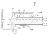
상술한 목적은, 평판형 LED 조명장치(100)로서, V홈(111)이 후면에 형성된 도광판(110); 상기 도광판의 후면에 부착된 반사시트(120); 상기 반사시트(120)의 후면에 설치되는 고정판(130); 상기 도광판(110)의 상측면에 접하여 설치되는 LED 광원(151)과 LED 기판(152)을 포함하는 광원부(150); 상기 광원부(150)에 밀착되어 상기 광원부를 감싸는 방열프레임(200); 및 상기 방열프레임(200)의 상방향 외측으로 돌출되도록 형성되어 상기 방열프레임(200)과의 사이에 별도의 수용공간을 형성하도록 하는 돌출부(210); 를 포함하되, 상기 방열프레임(200)은, 상기 도광판(110)의 상방에 형성되되, 상기 광원부(150)를 수용하여 상기 광원부(150)의 기판(152)에 밀착되어 상기 광원부를 감싸도록 형성된 제 1 수용부(220)와, 상기 도광판(110)의 후방에 형성되되, 상기 도광판(110)과 평행한 방향으로 수용되는 전원 공급용 기판(153)을 수용하여 밀착되게 감싸도록 형성되며, 상기 고정판(130)에 밀착되는 제1 단부(200a)를 포함하는 제 2 수용부(230)를 포함하며, 상기 방열프레임(200)은, 상기 도광판(110)의 전면에 밀착되는 상기 제2 단부(200b)로부터 상기 제1 수용부(220), 상기 제1 수용부(220)와 마주보는 위치의 상기 돌출부(210), 상기 제2 수용부(230), 및 상기 제1 단부(200a)까지가 일체로 형성되며, 상기 제 1 수용부(220)에는 상기 LED 기판(152)이 좌우측의 적어도 일 측면으로부터 슬라이드 방식으로 결합되도록 하고, 상기 제 2 수용부(230)에는 상기 전원 공급용 기판(153)이 좌우측의 적어도 일 측면으로부터 슬라이드 방식으로 결합되도록 함으로써, 평판형 LED 조명장치(100)의 두께를 슬림화할 수 있을 뿐만 아니라 상기 LED 기판 및 상기 전원 공급용 기판의 결합작업이 간편하게 이루어지도록 하며, 상기 돌출부(210)는 상기 방열프레임(200)에 대응한 길이로서 형성되어, 방열면적이 극대화되도록 함으로써 방열효과가 극대화되도록 하는 것을 특징으로 하는 평판형 LED 조명장치용 방열장치에 의해 달성된다.The above object is a flat panel type
삭제delete
본 발명의 평판형 LED 조명장치용 방열장치에 따르면, 도광판의 일측면에 광원부의 기판을 밀착되게 감싸는 방열프레임이 구성됨으로써 광원부에서 발생된 열이 이에 밀착된 방열프레임을 통해 전달될 뿐만 아니라 방열프레임의 돌출된 돌출부 또는 다수의 방열핀을 통해서 방열되므로 광원부의 방열이 원활하게 이루어져 광원의 열화와 조도의 저하가 방지되고, 광원의 수명이 연장되는 효과가 있다.According to the heat dissipation device for a flat panel LED lighting device of the present invention, the heat dissipation frame surrounding the substrate of the light source unit in close contact with the light guide plate is configured to not only transfer heat generated from the light source unit through the heat dissipation frame in close contact with the heat dissipation frame. Since the heat dissipation through the protruding protrusions or the plurality of heat radiation fins of the light source unit is smoothly radiated to prevent degradation of the light source and degradation of illuminance, it has the effect of extending the life of the light source.
이하, 본 발명의 바람직한 실시예를 첨부도면을 참조하여 상세히 설명한다.Hereinafter, preferred embodiments of the present invention will be described in detail with reference to the accompanying drawings.
첨부도면 도 3은 본 발명에 따른 평판형 LED 조명장치의 구성을 보인 분리사시도이고, 도 4는 도 3의 B-B선 단면도이며, 도 5는 본 발명의 다른 실시예에 따른 평판형 LED 조명장치의 구성을 보인 분리사시도이고, 도 6은 도 5의 C-C선 단면도이다.Figure 3 is an exploded perspective view showing the configuration of a flat panel LED lighting apparatus according to the present invention, Figure 4 is a cross-sectional view taken along line BB of Figure 3, Figure 5 is a flat panel LED lighting apparatus according to another embodiment of the present invention An exploded perspective view showing the configuration, Figure 6 is a cross-sectional view taken along line CC of FIG.
본 발명의 평판형 LED 조명장치(100)는 도 3 내지 도 6에 도시된 바와 같이, 투광 가능한 재질의 아크릴판으로 형성된 도광판(110)과, 상기 도광판(110)의 일측면에 설치되어 빛을 발광하는 광원부(150)를 포함한다.3 to 6, the flat
상기 도광판(110)의 후면에는 측면의 광원(151)에서 발광된 빛을 전면으로 균일하게 산란시키기 위한 V홈(111)이 수평 및 수직방향으로 다수개 형성되고, 상기 V홈(111)이 형성된 도광판(110)의 후면에는 PET 재질 또는 종이 재질의 반사시트(120)가 부착되어 설치되며, 상기 반사시트(120)의 후면에는 알루미늄 또는 스틸재로 이루어진 고정판(130)이 설치된다.On the rear surface of the
그리고, 상기 도광판(110)의 전면에는 빛을 전면으로 확산시켜 디스플레이하는 확산필름(140)이 부착되어 설치된다.In addition, the front of the
또한, 상기 광원부(150)는 광원(151)과, 이에 전기적으로 연결되어 광원(151)과 같이 항상 수반되는 기판(152)을 포함하고, 상기 광원부(150)는 도광판(110)의 일측에 설치되는 방열프레임(200)(300)의 내부에 수용되어 구비된다.In addition, the
여기서, 상기 광원(151)은 LED로 이루어지고, 이러한 LED는 온도에 제한받지 않고 어떤 환경에도 설치가 가능하며 기존의 형광램프에 비해 충격에 강하여 수명이 긴 장점이 있다.Here, the
이와 같이 구성된 평판형 LED 조명장치(100)는 통상적인 백라이트유닛 등의 조명수단을 포함하는 것으로, 이러한 평판형 LED 조명장치(100)는 엘시디(LCD), 광고용, 조명용, 전시조명, 유도로 및 데코레이션 등과 같이 다양한 형태로 사용될 수 있다.The flat panel
상기 방열프레임(200)(300)은 열전도율이 좋은 재질로서 형성되되, 바람직하게는 알루미늄 재질로 형성됨이 좋다.The
상기 방열프레임(200)은 도 3 및 도 4에 도시된 바와 같이, 상기 도광판(110)의 일측에서 광원부(150)를 그 내부에 수용하여 감싸는 한편 광원부(150)의 기판(152)에 밀착되게 설치된다.As shown in FIGS. 3 and 4, the
상기 방열프레임(200)은 그 일측에 광원부(150)를 수용하여 광원부(150)의 기판(152)에 밀착되어 감싸는 제 1 수용부(220)가 형성되고, 타측에는 또 다른 기판(153)을 수용하여 밀착되게 감싸는 제 2 수용부(230)가 형성된다.The
이때, 상기 제 1,2 수용부(220)(230)에는 각각의 기판(152)(153)이 슬라이드 결합됨으로써 평판형 LED 조명장치(100)의 두께를 슬림화할 수 있을 뿐만 아니라 이의 결합작업이 간편하게 이루어져 작업성이 향상된다.In this case, the
그리고, 상기 방열프레임(200)의 외측에는 외향 돌출된 돌출부(210)가 더 형성되고, 상기 돌출부(210)는 방열프레임(200)으로부터 도 4에 도시된 바와 같이 절곡 형성되어, 돌출부(210)와 방열프레임(200) 사이에 소정의 수용공간을 더 형성할 수도 있다.Further, an outwardly protruding
특히, 상기와 같이 돌출된 방열프레임(200)의 돌출부(210)는 방열프레임(200)에 대응한 길이로서 형성되어, 방열면적이 극대화됨으로써 방열효과가 극대화된다.In particular, the
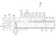
그리고, 상기 방열프레임(300)의 다른 실시예를 도 5 및 도 6에 도시하였고, 도면에 도시된 바와 같이 열전도율이 좋은 알루미늄 재질로 형성된 방열프레임(300)은 도광판(110)의 일측에서 광원부(150)를 그 내부에 수용하여 감싸는 한편 광원부(150)의 기판(152)에 밀착되게 설치된다.5 and 6 illustrate another embodiment of the
한편, 본 실시예에 따른 방열프레임(300)에도 전술한 실시예와 같은 제 1,2 수용부(320)(330)가 형성되되, 상기 제 1 수용부(320)는 그 내부에 광원부(150)를 수용하여 광원부(150)의 기판(152)에 밀착되어 감싸는 한편, 제 2 수용부(330)는, 도 6에 도시된 바와 같이 기판이 구비되지 않는 경우에는 도광판(110)의 후면에 설치되는 고정판(130)의 일측단부를 수용하여 밀착 설치된다.Meanwhile, the first and second
이와 같이 설치되는 기판(152) 및 고정판(130)은 각각 제 1,2 수용부(220)(230)에 슬라이드 결합됨으로써 평판형 LED 조명장치(100)의 두께를 슬림화할 수 있을 뿐만 아니라 이의 결합작업이 간편하게 이루어져 작업성이 향상된다.The
그리고, 상기 방열프레임(300)의 외측면 즉 제 1,2 수용부(320)(330)의 외측면에는 다수의 방열핀(310)이 돌출 형성되고, 상기 방열핀(310)의 표면에는 주름진 주름부(311)가 형성된다.In addition, a plurality of heat dissipation fins 310 protrude from the outer surface of the
이와 같이 돌출 형성된 다수의 방열핀(310)은 대기와의 접촉면적이 확대되어 방열프레임(300)의 방열효과를 향상시키되, 각 방열핀(310)에 형성된 주름부(311)에 의해서 방열면적이 최대한 확대됨으로써 방열프레임(300)의 방열효과가 극대화된다.As described above, the plurality of heat dissipation fins 310 protruded to increase the contact area with the air to improve the heat dissipation effect of the heat dissipation fins 300, but to maximize the heat dissipation area by the
한편, 상기와 같이 설치되는 방열프레임(200)(300)은 그 일측이 도광판(110)의 후면에 설치된 고정판(130)에 접하여 설치되는 바, 이때 상기 고정판(130)은 열전도율이 좋은 알루미늄 재질이나 스틸 재질로 이루어짐으로써 방열프레임(200)(300)으로부터 전도된 열을 방열시킬 수 있게 된다.On the other hand, the
따라서, 상기와 같이 설치되는 방열프레임(200)(300)은 그 내부에 광원부(150)가 수용됨과 아울러 광원부(150)의 기판(152)이 밀착 설치됨으로써 광원부(150)에서 발생되는 열이 기판(152)을 통해 이에 접한 방열프레임(200)(300)으로 전도된 후, 방열프레임(200)(300)에 돌출 형성된 돌출부(210) 또는 다수의 방열핀(310)에 의해 외부로 방열이 이루어지게 된다.Therefore, the
따라서, 돌출부(210) 또는 방열핀(310)에 의해서 방열프레임(200)(300)의 방열면적이 극대화됨으로써 방열효과가 향상되고, 발열에 따른 광원(151)의 조도저하 및 수명단축을 방지할 수 있게 된다.Therefore, the heat dissipation area of the
도 1은 일반적인 백라이트 유닛으로 사용되는 조명장치의 구성을 보인 후면도이다.1 is a rear view showing the configuration of a lighting device used as a general backlight unit.
도 2는 도 1의 A-A선 단면 일부 상세도이다.2 is a partial detailed cross-sectional view taken along the line A-A of FIG.
도 3은 본 발명에 따른 평판형 LED 조명장치의 구성을 보인 분리사시도이다.3 is an exploded perspective view showing the configuration of a flat panel LED lighting apparatus according to the present invention.
도 4는 도 3의 B-B선 단면도이다.4 is a cross-sectional view taken along the line B-B in FIG.
도 5는 본 발명의 다른 실시예에 따른 평판형 LED 조명장치의 구성을 보인 분리사시도이다.5 is an exploded perspective view showing the configuration of a flat panel LED lighting apparatus according to another embodiment of the present invention.
도 6은 도 5의 C-C선 단면도이다.6 is a cross-sectional view taken along the line C-C of FIG.
<도면의 주요부분에 대한 부호의 설명><Description of the symbols for the main parts of the drawings>
100 : 평판형 LED 조명장치110 : 도광판100: flat LED lighting device 110: light guide plate
111 : V홈120 : 반사시트111: V groove 120: Reflective sheet
130 : 고정판140 : 확산필름130: fixed plate 140: diffusion film
150 : 광원부151 : 광원150: light source 151: light source
152,153 : 기판200 : 방열프레임152,153: 200 substrate: heat radiation frame
210 : 돌출부220 : 제 1 수용부210: protrusion 220: first receiving portion
230 : 제 2 수용부300 : 방열프레임230: second receiving portion 300: heat dissipation frame
310 : 방열핀311 : 주름부310: heat radiation fin 311: wrinkles
320 : 제 1 수용부330 : 제 2 수용부320: first accommodating part 330: second accommodating part
Claims (4)
Translated fromKoreanPriority Applications (1)
| Application Number | Priority Date | Filing Date | Title |
|---|---|---|---|
| KR1020090042976AKR100960662B1 (en) | 2009-05-18 | 2009-05-18 | Led lighting apparatus |
Applications Claiming Priority (1)
| Application Number | Priority Date | Filing Date | Title |
|---|---|---|---|
| KR1020090042976AKR100960662B1 (en) | 2009-05-18 | 2009-05-18 | Led lighting apparatus |
Publications (1)
| Publication Number | Publication Date |
|---|---|
| KR100960662B1true KR100960662B1 (en) | 2010-06-08 |
Family
ID=42369463
Family Applications (1)
| Application Number | Title | Priority Date | Filing Date |
|---|---|---|---|
| KR1020090042976AExpired - Fee RelatedKR100960662B1 (en) | 2009-05-18 | 2009-05-18 | Led lighting apparatus |
Country Status (1)
| Country | Link |
|---|---|
| KR (1) | KR100960662B1 (en) |
Cited By (3)
| Publication number | Priority date | Publication date | Assignee | Title |
|---|---|---|---|---|
| US8235540B2 (en) | 2011-01-14 | 2012-08-07 | Lg Innotek Co., Ltd. | Backlight unit and display apparatus using the same |
| CN102679245A (en)* | 2012-05-21 | 2012-09-19 | 广州嘉庆电子有限公司 | Panel lamp |
| KR101538554B1 (en)* | 2013-11-22 | 2015-07-23 | 에이펙스인텍 주식회사 | LED illumination device type corner |
Citations (2)
| Publication number | Priority date | Publication date | Assignee | Title |
|---|---|---|---|---|
| KR100516123B1 (en)* | 2005-08-30 | 2005-09-21 | 주식회사 누리플랜 | A line type led illumination lamp |
| KR100664349B1 (en) | 2005-09-30 | 2007-01-02 | 자화전자(주) | Led board for illumination and illumination unit including the board |
- 2009
- 2009-05-18KRKR1020090042976Apatent/KR100960662B1/ennot_activeExpired - Fee Related
Patent Citations (2)
| Publication number | Priority date | Publication date | Assignee | Title |
|---|---|---|---|---|
| KR100516123B1 (en)* | 2005-08-30 | 2005-09-21 | 주식회사 누리플랜 | A line type led illumination lamp |
| KR100664349B1 (en) | 2005-09-30 | 2007-01-02 | 자화전자(주) | Led board for illumination and illumination unit including the board |
Cited By (3)
| Publication number | Priority date | Publication date | Assignee | Title |
|---|---|---|---|---|
| US8235540B2 (en) | 2011-01-14 | 2012-08-07 | Lg Innotek Co., Ltd. | Backlight unit and display apparatus using the same |
| CN102679245A (en)* | 2012-05-21 | 2012-09-19 | 广州嘉庆电子有限公司 | Panel lamp |
| KR101538554B1 (en)* | 2013-11-22 | 2015-07-23 | 에이펙스인텍 주식회사 | LED illumination device type corner |
Similar Documents
| Publication | Publication Date | Title |
|---|---|---|
| JP4726937B2 (en) | Liquid crystal display | |
| JP4656418B2 (en) | Lighting device and image display device | |
| KR20060000236A (en) | Backlight Unit of LCD | |
| US20130336008A1 (en) | Lighting Device | |
| CN101135810A (en) | Backlight unit and liquid crystal display device using same | |
| KR20070084641A (en) | LED backlight unit | |
| KR100924093B1 (en) | Ultra Slim Light Panel | |
| KR20070106134A (en) | Back light assembly and liquid crystal display device having same | |
| JPWO2008032460A1 (en) | Backlight device and display device using the same | |
| JP2008218238A (en) | Luminaire | |
| JP4777469B1 (en) | Illumination device and image display device including the same | |
| KR100960662B1 (en) | Led lighting apparatus | |
| KR101224107B1 (en) | Line bar type illumination system | |
| JP2012043558A (en) | Led lighting lamp | |
| JP4362410B2 (en) | Backlight device and liquid crystal display device | |
| KR101139948B1 (en) | The led lamp | |
| JP2009187718A (en) | Light source device | |
| JP2010103060A (en) | Display device | |
| KR20090119405A (en) | Backlight unit | |
| JP2009181916A (en) | Light source system | |
| KR101252851B1 (en) | Backlight assembly and liquid crystal display device having the same | |
| JP2008216406A5 (en) | ||
| JP2015108752A (en) | Liquid crystal display device | |
| KR100565890B1 (en) | Backlight unit with adhesive fixing heat radiation frame | |
| KR100971622B1 (en) | Combined Frame of LCD |
Legal Events
| Date | Code | Title | Description |
|---|---|---|---|
| A201 | Request for examination | ||
| PA0109 | Patent application | St.27 status event code:A-0-1-A10-A12-nap-PA0109 | |
| PA0201 | Request for examination | St.27 status event code:A-1-2-D10-D11-exm-PA0201 | |
| A302 | Request for accelerated examination | ||
| PA0302 | Request for accelerated examination | St.27 status event code:A-1-2-D10-D17-exm-PA0302 St.27 status event code:A-1-2-D10-D16-exm-PA0302 | |
| D13-X000 | Search requested | St.27 status event code:A-1-2-D10-D13-srh-X000 | |
| D14-X000 | Search report completed | St.27 status event code:A-1-2-D10-D14-srh-X000 | |
| E902 | Notification of reason for refusal | ||
| PE0902 | Notice of grounds for rejection | St.27 status event code:A-1-2-D10-D21-exm-PE0902 | |
| E13-X000 | Pre-grant limitation requested | St.27 status event code:A-2-3-E10-E13-lim-X000 | |
| P11-X000 | Amendment of application requested | St.27 status event code:A-2-2-P10-P11-nap-X000 | |
| P13-X000 | Application amended | St.27 status event code:A-2-2-P10-P13-nap-X000 | |
| E90F | Notification of reason for final refusal | ||
| PE0902 | Notice of grounds for rejection | St.27 status event code:A-1-2-D10-D21-exm-PE0902 | |
| P11-X000 | Amendment of application requested | St.27 status event code:A-2-2-P10-P11-nap-X000 | |
| P13-X000 | Application amended | St.27 status event code:A-2-2-P10-P13-nap-X000 | |
| E701 | Decision to grant or registration of patent right | ||
| PE0701 | Decision of registration | St.27 status event code:A-1-2-D10-D22-exm-PE0701 | |
| GRNT | Written decision to grant | ||
| PR0701 | Registration of establishment | St.27 status event code:A-2-4-F10-F11-exm-PR0701 | |
| PR1002 | Payment of registration fee | St.27 status event code:A-2-2-U10-U11-oth-PR1002 Fee payment year number:1 | |
| PG1601 | Publication of registration | St.27 status event code:A-4-4-Q10-Q13-nap-PG1601 | |
| R18-X000 | Changes to party contact information recorded | St.27 status event code:A-5-5-R10-R18-oth-X000 | |
| FPAY | Annual fee payment | Payment date:20130523 Year of fee payment:4 | |
| PR1001 | Payment of annual fee | St.27 status event code:A-4-4-U10-U11-oth-PR1001 Fee payment year number:4 | |
| LAPS | Lapse due to unpaid annual fee | ||
| PC1903 | Unpaid annual fee | St.27 status event code:A-4-4-U10-U13-oth-PC1903 Not in force date:20140525 Payment event data comment text:Termination Category : DEFAULT_OF_REGISTRATION_FEE | |
| PC1903 | Unpaid annual fee | St.27 status event code:N-4-6-H10-H13-oth-PC1903 Ip right cessation event data comment text:Termination Category : DEFAULT_OF_REGISTRATION_FEE Not in force date:20140525 | |
| P22-X000 | Classification modified | St.27 status event code:A-4-4-P10-P22-nap-X000 | |
| P22-X000 | Classification modified | St.27 status event code:A-4-4-P10-P22-nap-X000 |