KR100960586B1 - Network system - Google Patents
Network systemDownload PDFInfo
- Publication number
- KR100960586B1 KR100960586B1KR20087003702AKR20087003702AKR100960586B1KR 100960586 B1KR100960586 B1KR 100960586B1KR 20087003702 AKR20087003702 AKR 20087003702AKR 20087003702 AKR20087003702 AKR 20087003702AKR 100960586 B1KR100960586 B1KR 100960586B1
- Authority
- KR
- South Korea
- Prior art keywords
- identifier
- equipment
- network
- server
- information
- Prior art date
- Legal status (The legal status is an assumption and is not a legal conclusion. Google has not performed a legal analysis and makes no representation as to the accuracy of the status listed.)
- Expired - Fee Related
Links
Images


Classifications
- G—PHYSICS
- G06—COMPUTING OR CALCULATING; COUNTING
- G06F—ELECTRIC DIGITAL DATA PROCESSING
- G06F13/00—Interconnection of, or transfer of information or other signals between, memories, input/output devices or central processing units
- H—ELECTRICITY
- H04—ELECTRIC COMMUNICATION TECHNIQUE
- H04L—TRANSMISSION OF DIGITAL INFORMATION, e.g. TELEGRAPHIC COMMUNICATION
- H04L41/00—Arrangements for maintenance, administration or management of data switching networks, e.g. of packet switching networks
- H04L41/50—Network service management, e.g. ensuring proper service fulfilment according to agreements
- H04L41/5041—Network service management, e.g. ensuring proper service fulfilment according to agreements characterised by the time relationship between creation and deployment of a service
- H04L41/5054—Automatic deployment of services triggered by the service manager, e.g. service implementation by automatic configuration of network components
- G—PHYSICS
- G06—COMPUTING OR CALCULATING; COUNTING
- G06F—ELECTRIC DIGITAL DATA PROCESSING
- G06F8/00—Arrangements for software engineering
- G06F8/40—Transformation of program code
- G06F8/54—Link editing before load time
- H—ELECTRICITY
- H04—ELECTRIC COMMUNICATION TECHNIQUE
- H04L—TRANSMISSION OF DIGITAL INFORMATION, e.g. TELEGRAPHIC COMMUNICATION
- H04L12/00—Data switching networks
- H04L12/28—Data switching networks characterised by path configuration, e.g. LAN [Local Area Networks] or WAN [Wide Area Networks]
- H—ELECTRICITY
- H04—ELECTRIC COMMUNICATION TECHNIQUE
- H04L—TRANSMISSION OF DIGITAL INFORMATION, e.g. TELEGRAPHIC COMMUNICATION
- H04L12/00—Data switching networks
- H04L12/28—Data switching networks characterised by path configuration, e.g. LAN [Local Area Networks] or WAN [Wide Area Networks]
- H04L12/2803—Home automation networks
- H04L12/2816—Controlling appliance services of a home automation network by calling their functionalities
- H04L12/2818—Controlling appliance services of a home automation network by calling their functionalities from a device located outside both the home and the home network
- H—ELECTRICITY
- H04—ELECTRIC COMMUNICATION TECHNIQUE
- H04L—TRANSMISSION OF DIGITAL INFORMATION, e.g. TELEGRAPHIC COMMUNICATION
- H04L9/00—Cryptographic mechanisms or cryptographic arrangements for secret or secure communications; Network security protocols
- H04L9/40—Network security protocols
- H—ELECTRICITY
- H04—ELECTRIC COMMUNICATION TECHNIQUE
- H04L—TRANSMISSION OF DIGITAL INFORMATION, e.g. TELEGRAPHIC COMMUNICATION
- H04L12/00—Data switching networks
- H04L12/28—Data switching networks characterised by path configuration, e.g. LAN [Local Area Networks] or WAN [Wide Area Networks]
- H04L12/2803—Home automation networks
- H04L2012/2847—Home automation networks characterised by the type of home appliance used
- H04L2012/2849—Audio/video appliances
Landscapes
- Engineering & Computer Science (AREA)
- Signal Processing (AREA)
- Computer Networks & Wireless Communication (AREA)
- Theoretical Computer Science (AREA)
- Automation & Control Theory (AREA)
- General Engineering & Computer Science (AREA)
- Physics & Mathematics (AREA)
- General Physics & Mathematics (AREA)
- Computer Security & Cryptography (AREA)
- Software Systems (AREA)
- Data Exchanges In Wide-Area Networks (AREA)
- Computer And Data Communications (AREA)
- Stored Programmes (AREA)
- Selective Calling Equipment (AREA)
- Telephonic Communication Services (AREA)
Abstract
Translated fromKoreanDescription
Translated fromKorean본 발명은 네트워크 기기에 의하여 네트워크에 접속되는 장비(equipment)들에 대하여 원격 제어 또는 원격 모니터링을 가능하도록 하기 위한 네트워크 시스템에 관한 것이다.The present invention relates to a network system for enabling remote control or remote monitoring of equipment connected to a network by a network device.
이전에, IPv6 네트워크에 접속되는 단말 기기(terminal device)에 의하여 비 IP 네트워크(non-IP network)에 연결되는 장비들을 제어/모니터링하는 시스템이 제안되었다. 이 시스템은 IPv6 네트워크를 위한 네트워크 ID 뿐만 아니라 비 IPv6 네트워크 장비들의 식별 정보(identification information) 및 인터페이스 ID를 획득하며, 이러한 ID들로부터 IPv6 어드레스들을 생성하며, 생성된 어드레스들과 식별 정보 사이의 대응(correspondence)을 관리함으로써, 비 IP 네트워크 장비들 및 IPv6 네트워크 단말 기기 사이의 통신을 가능하도록 하는 게이트웨이(gateway)를 갖는다. 이러한 게이트웨이에 의하여, 이 장비들은 단말 기기에 의하여 제어 또는 모니터링될 수 있다.Previously, a system for controlling / monitoring equipment connected to a non-IP network by a terminal device connected to an IPv6 network has been proposed. The system obtains identification information and interface IDs of non-IPv6 network equipments as well as network IDs for IPv6 networks, generates IPv6 addresses from these IDs, and maps between the generated addresses and identification information ( By managing correspondence, it has a gateway that enables communication between non-IP network equipments and IPv6 network terminal devices. By such a gateway, these equipments can be controlled or monitored by the terminal device.
예를 들어, 이러한 종류의 네트워크 시스템은 일본 공개 특허 제2003-60664호에 기재되어 있다. 비 IPv6 장비들을 사용하는 이러한 시스템에서, IPv6 네트워크 단말 기기는 데스티네이션 IPv6 어드레스(destination IPv6 address)를 포함하 는 헤더(header)를 갖는 패킷(packet)을 전달하며, IPv6 어드레스는 게이트웨이에서 비 IPv6 장비에 할당된다. 따라서, 단말 기기가 복수의 장비들에 액세스할 경우에, 장비들 각각에 대응하는 IPv6 어드레스를 생성하는 것이 필요하게 된다. 즉, IPv6 어드레스를 고려할 필요가 있다. 덧붙여, 동일한 동작을 수행하기 위한 장비들의 수가 증가될 경우라도, 추가되는 장비에 대응하는 IPv6 어드레스를 새롭게 생성할 필요가 있다. 따라서 복수의 장비들을 단일 식별자(identifier)를 사용하여 제어하거나 모니터링할 수 없으며, 복수의 식별자가 단일 장비에 할당될 수 없는 불편함이 있다. 또한 서비스들을 제공하기 위한 장비들의 수의 증가에도 유연하게 대처하는 것이 가능하지 않다.For example, this kind of network system is described in Japanese Laid-Open Patent No. 2003-60664. In such a system using non-IPv6 devices, an IPv6 network terminal device carries a packet with a header containing a destination IPv6 address, where the IPv6 address is sent at the gateway to the non-IPv6 device. Is assigned to. Therefore, when the terminal device accesses a plurality of devices, it is necessary to generate an IPv6 address corresponding to each of the devices. In other words, it is necessary to consider IPv6 addresses. In addition, even when the number of devices for performing the same operation is increased, it is necessary to generate a new IPv6 address corresponding to the added device. Therefore, a plurality of devices cannot be controlled or monitored using a single identifier, and a plurality of devices cannot be assigned to a single device. It is also not possible to flexibly cope with an increase in the number of equipments for providing services.
따라서 상술한 문제점들을 고려하여, 본 발명의 주요 목적은 서비스를 제공하기 위한 장비들의 수를 쉽게 증가시키며, 클라이언트의 요구에 따라서 장비들에 대한 원격 제어 또는 모니터링을 효과적으로 수행할 수 있는 네트워크 시스템을 제공하는 것이다.Accordingly, in view of the above-described problems, a main object of the present invention is to easily increase the number of equipments for providing a service, and to provide a network system that can effectively perform remote control or monitoring of equipments according to a client's request. It is.
즉, 본 발명의 네트워크 시스템은 복수의 장비들 및 네트워크를 통하여 상기 장비들에 연결되는 네트워크 기기를 포함하며, 상기 장비(들)가 상기 네트워크 기기로부터 입력되는 서비스 요청에 따라서 오브젝트를 실행하도록 구성되고,That is, the network system of the present invention includes a plurality of devices and a network device connected to the devices through a network, wherein the device (s) is configured to execute an object according to a service request input from the network device. ,
오브젝트 식별자가 상기 오브젝트에 할당되고,An object identifier is assigned to the object,
상기 네트워크 기기는 상기 오브젝트 식별자를 지정하기 위하여 구성되는 식별자 지정부(specifying portion)를 가지고,The network device has an identifier specifying portion configured to designate the object identifier,
상기 장비들은 동일한 오브젝트 식별자가 할당되는 오브젝트들을 갖는 복수의 장비들을 포함하며,The devices include a plurality of devices with objects that are assigned the same object identifier,
상기 네트워크 기기가 상기 식별자 지정부에 의하여 지정되는 동일한 오브젝트 식별자를 사용하여 서비스 요청을 수행하는 경우에, 복수의 장비들은 동일한 오브젝트 식별자를 갖는 상기 오브젝트들 내에서 정의되는 동일한 서비스를 제공한다.When the network device performs a service request using the same object identifier specified by the identifier designator, a plurality of devices provide the same service defined in the objects having the same object identifier.
본 발명의 네트워크 시스템에 따르면, 클라이언트(즉, 사용자)가 네트워크 통신을 위하여 사용되는 장비의 IP 어드레스와 같은 지정 식별 정보를 고려할 필요없이, 복수의 장비들의 오브젝트들에 동일한 오브젝트 식별자를 할당함으로써 복수의 장비들에게 일괄적으로 동일한 서비스를 실행하도록 허용할 수 있다. 또한, 서비스를 제공하기 위한 장비들의 수의 증가에 유연하게 대처할 수 있다.According to the network system of the present invention, a plurality of devices may be allocated by assigning the same object identifier to objects of a plurality of devices, without the client (i.e., user) having to consider designation identification information such as the IP address of the equipment used for network communication. You can allow devices to run the same service in batches. In addition, it is possible to flexibly cope with the increase in the number of equipment for providing a service.
본 발명의 다른 목적은 상술한 네트워크 시스템과 동일한 기본 구성을 가지며, 아래의 기능들을 포함하는 네트워크 시스템을 제공하는 것이다. 즉, 이 네트워크 시스템은 복수의 장비들 및 네트워크를 통하여 상기 장비들에 연결되는 네트워크 기기를 포함하며, 상기 장비(들)가 상기 네트워크 기기로부터 입력되는 서비스 요청에 따라서 오브젝트를 실행하도록 구성되고,Another object of the present invention is to provide a network system having the same basic configuration as the above-described network system and including the following functions. That is, the network system includes a plurality of devices and a network device connected to the devices through a network, wherein the device (s) is configured to execute an object according to a service request input from the network device,
오브젝트 식별자가 상기 오브젝트에 할당되고,An object identifier is assigned to the object,
상기 네트워크 기기는 상기 오브젝트 식별자를 지정하도록 구성되는 식별자 지정부을 가지고,The network device has an identifier designation unit configured to designate the object identifier,
상기 장비들은 상이한 오브젝트 식별자들이 할당되는 복수의 오브젝트들을 갖는 장비를 포함하며, 상기 네트워크 기기가 상기 식별자 지정부에 의하여 지정되는 상이한 오브젝트 식별자들 중 하나의 사용에 의하여 서비스 요청을 수행하는 경우에, 상기 장비는 지정되는 오브젝트 식별자를 갖는 상기 오브젝트들 내에서 정의되는 서비스를 제공한다.The devices include a device having a plurality of objects to which different object identifiers are assigned, and when the network device performs a service request by using one of the different object identifiers specified by the identifier designator, the The equipment provides a service defined within the objects with the specified object identifier.
이 네트워크 시스템에 따르면, 단일 장비가 상이한 오브젝트 식별자들이 할당되는 복수의 오브젝트들을 갖도록 허용되기 때문에, 매우 다양한 서비스들이 단일 장비에 의하여 제공될 수 있다.According to this network system, since a single equipment is allowed to have a plurality of objects to which different object identifiers are assigned, a wide variety of services can be provided by a single equipment.
네트워크 시스템에 의하여 장비(들)에 대한 원격 모니터링을 수행할 경우에, 장비들 각각은 장비의 서비스를 제공하기 위한 처리를 실행하기 위하여 구성되는 기능부 및 오브젝트 내에서 정의되며 기능부와 함께 서비스를 제공하도록 요구되는 정보를 주고받도록 구성되는 정보 처리부를 포함하는 것이 바람직하다. 오브젝트 내에서 정의되는 정보는 오브젝트가 네트워크 기기에 의하여 액세스될 경우에 정보 처리부로부터 기능부로 전송되는, 서비스를 제공하기 위한 동작 명령 함수, 오브젝트가 네트워크 기기의 요청에 의하여 액세스되는 경우에 네트워크 기기로 전송되는, 기능부의 현재 상태를 나타내는 변수 및 오브젝트가 네트워크 기기에 의하여 미리 액세스되는 조건 하에서 기능부의 상태 변화가 발생하는 경우 네트워크 기기로 전송되는 이벤트 정보를 포함한다.When performing remote monitoring of the equipment (s) by the network system, each of the equipments is defined within a functional unit and an object configured to execute a process for providing the service of the equipment and the service together with the functional unit. It is preferable to include an information processing unit configured to exchange information required to be provided. The information defined in the object is an operation command function for providing a service, which is transmitted from the information processing unit to the functional unit when the object is accessed by the network device, and transmitted to the network device when the object is accessed at the request of the network device. And event information transmitted to the network device when a state change of the functional part occurs under a condition in which a variable and an object indicating a current state of the functional part are previously accessed by the network device.
본 발명의 네트워크 시스템의 바람직한 실시예에 있어서, 오브젝트 식별자는 장비의 오브젝트의 고유 식별자 및 상기 장비의 기능(들)에 따라서 정의되는 적어도 하나의 인터페이스 식별자를 포함한다. 네트워크 기기가 오브젝트 식별자를 사용하여 서비스 요청을 수행하는 경우에, 고유 식별자 및 인터페이스 식별자의 조합에 대응하는 특정 서비스가 실행될 수 있다.In a preferred embodiment of the network system of the present invention, the object identifier includes a unique identifier of the object of the equipment and at least one interface identifier defined according to the function (s) of the equipment. When the network device performs the service request using the object identifier, a specific service corresponding to the combination of the unique identifier and the interface identifier can be executed.
또한, 본 발명의 네트워크 시스템의 더 바람직한 실시예로서, 네트워크 기기가 클라이언트 단말 기기 및 네트워크를 통하여 장비들 및 클라이언트 단말 기기 사이에서 연결되는 서버를 포함하고,Further, as a more preferred embodiment of the network system of the present invention, the network device includes a client terminal device and a server connected between the devices and the client terminal device via a network,
서버는 클라이언트 단말 기기로부터 제공되는 서비스 요청에 따라서 서버측 오브젝트를 실행하며, 이로 인하여 장비(들)로 장비측 오브젝트를 실행하기 위한 서비스 요청을 수행하고,The server executes the server-side object according to the service request provided from the client terminal device, thereby performing a service request for executing the equipment-side object with the equipment (s),
클라이언트 단말 기기는 서버측 오브젝트에 의하여 할당되는 제1 식별자를 사용하여 서비스 요청을 수행하며, 서버는 장비측 오브젝트에 할당되는 제2 식별자를 사용하여 서비스 요청을 수행하며;The client terminal device performs the service request using the first identifier assigned by the server-side object, and the server performs the service request using the second identifier assigned to the equipment-side object;
제2 식별자는 제1 식별자의 사용에 의하여 클라이언트 단말 기기로부터 제공되는 서버측 오브젝트를 실행하기 위한 서비스 요청에 따라서 장비측 오브젝트를 실행하는 장비의 기능(들)(예를 들어, "로킹" 및 "에어 컨디셔닝")에 따라서 정의되는 적어도 하나의 식별자를 포함하며, 그리고The second identifier is the function (s) of the equipment that executes the equipment-side object in response to a service request for executing the server-side object provided from the client terminal device by use of the first identifier (eg, "locking" and " Air conditioning ") and at least one identifier defined by
서버는 제1 식별자 및 제2 식별자 사이의 대응 관계를 설정하기 위하여 구성되는 식별자 설정부를 가진다.The server has an identifier setting unit configured to establish a corresponding relationship between the first identifier and the second identifier.
이 경우에 있어서, 장비측 오브젝트의 정보 정의를 변경하거나 장비측 오브젝트를 추가할 필요없이, 서버측 오브젝트에 의하여 새로운 서비스를 제공할 수 있다. 또한, 추가적인 장비(들)가 연결되는 경우조차도, 현존하는 장비(들)에 관계없이 제공되는 서비스들의 종류를 확장할 수 있다. 더욱이, 장비측 오브젝트의 실행 요청이 장비에 의하여 제공되는 서비스를 획득하기 위하여 서버를 통하여 전송되기 때문에, 클라이언트 네트워크 기기에 대한 부담을 줄일 수 있는 이점이 있다.In this case, a new service can be provided by the server side object without changing the information definition of the equipment side object or adding the equipment side object. In addition, even when additional equipment (s) are connected, it is possible to extend the type of services provided regardless of the existing equipment (s). Furthermore, since the execution request of the equipment-side object is transmitted through the server to obtain the service provided by the equipment, there is an advantage that the burden on the client network device can be reduced.
상술한 바람직한 실시예에 따른 네트워크 시스템에 있어서, 제2 식별자가 장비측 오브젝트의 고유 식별자(OID) 및 장비의 기능(들)(장비에 의하여 제공되는 서비스 내용(들))에 따라서 정의되는 적어도 하나의 인터페이스 식별자(IID)를 포함하고, 서버는 고유 식별자와 적어도 하나의 인터페이스 식별자의 조합과 오브젝트 식별자를 갖는 오브젝트에 액세스하기 위하여 사용되는 네트워크 통신을 위한 접속 어드레스 정보(네트워크 접속 관련 정보) 사이의 관계를 나타내는 라우팅 테이블을 준비하도록 구성되는 라우팅 기능부를 가지며, 라우팅 처리를 실행하는 것이 더욱 바람직하다.In the network system according to the above-described preferred embodiment, the second identifier is at least one defined according to the unique identifier (OID) of the equipment-side object and the function (s) (service content (s) provided by the equipment) of the equipment. A relationship between a combination of a unique identifier and at least one interface identifier and connection address information (network connection related information) for network communication used to access an object having an object identifier; It is more preferable to have a routing function configured to prepare a routing table indicative of the following.
상술한 바람직한 실시예에 따른 네트워크 시스템에 있어서, 제1 오브젝트 식별자는 서버측 오브젝트의 고유 식별자 및 클라이언트로 제공되는 서비스 내용(들)에 따라서 정의되는 적어도 하나의 인터페이스 식별자를 포함하고,In the network system according to the above-described preferred embodiment, the first object identifier includes at least one interface identifier defined according to the unique identifier of the server-side object and the service content (s) provided to the client,
제2 오브젝트 식별자는 장비측 오브젝트의 고유 식별자 및 장비의 기능(들)에 따라서 정의되는 적어도 하나의 인터페이스 식별자를 포함하고,The second object identifier comprises at least one interface identifier defined according to the unique identifier of the equipment-side object and the function (s) of the equipment,
식별자 설정부가 제1 식별자의 고유 식별자와 적어도 하나의 인터페이스 식별자의 조합과, 제2 식별자의 고유 식별자와 적어도 하나의 인터페이스 식별자의 조합 사이의 대응 관계를 설정하도록 구성되는 것이 특히 바람직하다.It is particularly preferable that the identifier setting unit is configured to set a correspondence between the combination of the unique identifier of the first identifier and the at least one interface identifier and the combination of the unique identifier and the at least one interface identifier of the second identifier.
이 경우에는, 특정한 장비에 의하여 특정한 서비스를 제공하는 것이 가능해진다. 또한, 서비스 요청이 복수의 장비들의 오브젝트들에 할당되는 동일한 인터페이스 식별자의 사용에 의하여 수행되는 경우에, 인터페이스 식별자의 정의 내용(definition contet)에 대응하는 동일한 서비스가 상기 장비들에 의하여 일괄적으로 제공될 수 있다. 따라서 클라이언트가 필요로 하는 다양한 정보에 적절하게 응답할 수 있으며, 유연하면서 쉽게 장비(들)의 추가와 같은 시스템 변경에 대처할 수 있다.In this case, it becomes possible to provide a specific service by specific equipment. In addition, when a service request is performed by use of the same interface identifier assigned to objects of a plurality of devices, the same service corresponding to the definition contet of the interface identifier is collectively provided by the devices. Can be. This allows the client to respond appropriately to a variety of information needed by the client and can be flexibly and easily coped with system changes such as the addition of equipment (s).
서버는, 서버측 오브젝트의 내용에 따라서 클라이언트 단말 기기로부터 제공되는 서버측 오브젝트의 서비스 요청을 통하여, 장비(들)가 장비측 오브젝트를 실행하도록 허용함으로써 획득되는 데이터를 처리하며, 이후 처리된 데이터를 클라이언트 단말 기기로 전송하는 것 또한 바람직하다. 장비(들)가 클라이언트로 장비측 오브젝트를 실행하도록 허용함으로써 획득되는 미가공 데이터(raw data)를 단순히 제공하는 경우에 덧붙여, 클라이언트에 의하여 요구되는 정보로 미가공 데이터를 처리하며, 이후 처리된 데이터를 클라이언트로 제공하는 것이 가능하다. 따라서 클라이언트는 보다 다양한 서비스들을 받을 수 있다.The server processes the data obtained by allowing the equipment (s) to execute the equipment-side object through the service request of the server-side object provided from the client terminal device according to the contents of the server-side object, and then processes the processed data. It is also desirable to transmit to the client terminal device. In addition to simply providing the raw data obtained by allowing the equipment (s) to execute the equipment-side object to the client, it processes the raw data with the information required by the client and then processes the processed data into the client. It is possible to provide as. Thus, the client can receive more various services.
서버는 미리 정해진 통신 프로토콜을 SOAP로 변환하여, 변환된 SOAP를 전송하며, 수신한 SOAP를 미리 정해진 통신 프로토콜로 변환하는 기능들을 가지는 것이 바람직하다. 이 경우에 있어서, 네트워크를 위하여 제공되는 방화벽을 넘어 장비들과 네트워크 기기 사이의 통신을 설정할 수 있다.The server preferably has functions of converting a predetermined communication protocol into SOAP, transmitting the converted SOAP, and converting the received SOAP into a predetermined communication protocol. In this case, communication between the devices and the network device can be established beyond the firewall provided for the network.
본 발명의 바람직한 실시예에 따른 네트워크 시스템은 아래와 같이 정의될 수 있다. 즉, 이 네트워크 시스템은, 복수의 장비들, 네트워크를 통하여 장비(들)에 의하여 제공되는 서비스(들)를 위한 요청을 장비(들)로 전송하도록 구성되는 적어도 하나의 네트워크 기기를 포함한다. 장비는 장비의 서비스를 제공하기 위한 처리를 실행하도록 구성되는 기능부와, 액세스를 위하여 오브젝트 식별자가 할당되는, 서비스를 제공하기 위하여 사용되는 정보를 정의하는 적어도 하나의 오브젝트를 갖고, 정의에 따라서 기능부과 정보를 주고받도록 구성되는 정보 처리부로 형성된다. 네트워크 기기는 오브젝트 식별자의 사용과 함께 네트워크를 통하여 장비(들)로 요청을 직접 또는 간접적으로 전송하는 기능을 가진다. 장비들 각각의 정보 처리부들이 가진 오브젝트들이 동일한 정의 내용를 가질 경우에, 동일한 오브젝트 식별자가 상기 오브젝트들에 할당된다. 네트워크 기기가 장비들의 오브젝트들에 할당된 동일한 오브젝트 식별자를 사용하여 서비스 요청을 수행하는 경우에, 장비들 각각은 오브젝트 내에서 정의되는 동일한 서비스를 제공하기 위하여 오브젝트 식별자에 대응하는 요청된 오브젝트를 실행한다.A network system according to a preferred embodiment of the present invention may be defined as follows. That is, the network system includes a plurality of devices, at least one network device configured to send a request to the device (s) for service (s) provided by the device (s) via the network. The equipment has a function unit configured to perform a process for providing a service of the equipment, and at least one object defining information used to provide a service to which an object identifier is assigned for access, and function according to the definition. And an information processing unit configured to send and receive charging information. The network device has the ability to send a request directly or indirectly to the device (s) over the network with the use of an object identifier. When the objects possessed by the information processing units of the equipments have the same definition content, the same object identifier is assigned to the objects. When the network device performs a service request using the same object identifier assigned to the objects of the devices, each of the devices executes the requested object corresponding to the object identifier to provide the same service defined within the object. .
또한, 본 발명의 다른 바람직한 실시예에 따른 네트워크 시스템은 아래와 같이 정의될 수 있다. 즉, 이 네트워크 시스템은, 복수의 장비들과, 네트워크를 통하여 이 장비(들)로 서비스 요청을 실행하도록 구성되는 적어도 하나의 네트워크 기기를 포함한다. 장비는 장비의 서비스를 제공하기 위한 처리를 실행하도록 구성되는 기능부, 액세스를 위하여 오브젝트 식별자가 할당되는, 서비스를 제공하기 위하여 사용되는 정보를 정의하는 적어도 하나의 오브젝트를 가지며, 정의에 따라서 기능부와 정보를 주고받도록 구성되는 정보 처리부로 형성된다. 네트워크 기기는 오브젝트 식별자의 사용에 의하여 네트워크를 통하여 장비(들)로 서비스 요청을 직접 또는 간접적으로 전송하는 기능을 가진다. 상이한 오브젝트 식별자들이 장비들 중 하나의 정보 처리부가 가진 복수의 오브젝트들에 할당된다. 네트워크 기기는 장비들 중 하나 내에 있는 오브젝트들에 할당되는 오브젝트 식별자들 중 하나를 지정하는 기능을 가진다. 장비들 중 하나는 오브젝트 내에서 정의되는 서비스를 제공하기 위하여 지정된 오브젝트 식별자에 대응하는 오브젝트를 실행한다.In addition, a network system according to another preferred embodiment of the present invention may be defined as follows. That is, the network system includes a plurality of devices and at least one network device configured to execute a service request to the device (s) via the network. The equipment has a functional unit configured to execute a process for providing a service of the equipment, at least one object defining information used to provide a service to which an object identifier is assigned for access, and the functional unit according to the definition. And an information processing unit configured to exchange information with. The network device has the ability to send a service request directly or indirectly to the device (s) via the network by use of an object identifier. Different object identifiers are assigned to a plurality of objects with one information processing part of the equipments. The network device has a function of specifying one of the object identifiers assigned to the objects within one of the devices. One of the devices executes the object corresponding to the specified object identifier to provide a service defined within the object.
상술한 바람직한 실시예에 따른 네트워크 시스템에 따르면, 사용자가 네트워크 통신을 위하여 사용되는 IP 어드레스와 같은 지정 식별 정보를 고려할 필요없이, 장비들을 제어 또는 모니터링할 수 있다. 또한, 동일한 오브젝트 식별자가 복수의 장비들의 오브젝트들에 할당되는 경우에, 동일한 서비스가 상기 장비들에 의하여 제공될 수 있다. 동시에, 상이한 오브젝트 식별자들이 장비들 중 하나의 오브젝트들에 할당되는 경우에, 매우 다양한 서비스들이 단일 장비에 의하여 제공될 수 있다.According to the network system according to the above-described preferred embodiment, the user can control or monitor the equipments without having to consider specific identification information such as an IP address used for network communication. In addition, when the same object identifier is assigned to objects of a plurality of devices, the same service may be provided by the devices. At the same time, in the case where different object identifiers are assigned to one of the devices, a wide variety of services can be provided by a single device.
상기한 네트워크 시스템의 바람직한 실시예에 있어서, 고유 식별자가 각 장비의 정보 처리부 내의 오브젝트들 각각에 할당된다. 오브젝트들 각각은 기능부 및 정보 처리부 사이에서 주고받는 정보를 정의하는 입력/출력 정의 기능을 가지며, 임의의 인터페이스 식별자가 입력/출력 정의 기능에 할당된다. 네트워크 기기가 장비(들)의 정보 처리부의 오브젝트에 액세스하기 위하여 오브젝트 식별자를 사용함으로써 장비(들)에 요청을 전송하는 경우에 있어서, 서비스를 제공하도록 요구되는 정보가 복수의 오브젝트들 하에서 동일한 인터페이스 식별자를 가진 입력/출력 정의 기능에 의하여 정의되는 정보인 때에는, 동일한 서비스가 오브젝트 식별자로서 동일한 인터페이스 식별자를 사용함으로써 복수의 장비들로부터 일괄적으로 제공될 수 있다. 또한, 서비스를 제공하도록 요구되는 정보가 지정 오브젝트의 지정 입력/출력 정의 기능에 의하여 정의되는 정보인 경우에, 지정 서비스는 오브젝트의 고유 식별자와, 오브젝트 식별자로서의 입력/출력 정의 기능의 인터페이스 식별자의 조합을 사용함으로써 특정 장비로부터 제공될 수 있다.In a preferred embodiment of the network system described above, a unique identifier is assigned to each of the objects in the information processing section of each equipment. Each of the objects has an input / output definition function that defines information exchanged between the function unit and the information processing unit, and an arbitrary interface identifier is assigned to the input / output definition function. In the case where the network device sends a request to the equipment (s) by using an object identifier to access an object of the information processing unit of the equipment (s), the information required to provide a service is the same interface identifier under the plurality of objects. When the information is defined by the input / output definition function having the same, the same service can be provided collectively from a plurality of devices by using the same interface identifier as the object identifier. In addition, when the information required to provide the service is information defined by the designated input / output definition function of the designated object, the designated service is a combination of the unique identifier of the object and the interface identifier of the input / output definition function as the object identifier. By using it can be provided from a particular equipment.
상기 네트워크 시스템의 보다 바람직한 실시예에 있어서, 서버는 네트워크 상에서 제공된다. 상기 서버는 네트워크에 접속되는 장비들을 검출하며, 검출된 장비의 정보 처리부 내의 오브젝트의 오브젝트 식별자 및 오브젝트 식별자를 가진 오브젝트에 액세스하기 위하여 사용되는 네트워크 연결 관계 정보 사이의 대응 관계를 저장하기 위한 테이블을 갖는다. 테이블의 내용에 따라서 네트워크를 통하여 네트워크 기기로부터 장비(들)로 제공되는 서비스 요청을 위한 라우팅 처리를 실행함으로써, 서비스 요청에 대응하는 장비(들)의 오브젝트(들)의 실행 요청이 서버를 통하여 전송된다. 따라서 클라이언트 네트워크 기기의 부담을 줄일 수 있다.In a more preferred embodiment of the network system, the server is provided on the network. The server has a table for detecting equipment connected to the network and storing a correspondence between the object identifier of the object in the information processing unit of the detected equipment and the network connection relation information used to access the object with the object identifier. . By executing the routing process for the service request provided from the network device to the device (s) via the network according to the contents of the table, the execution request of the object (s) of the device (s) corresponding to the service request is transmitted through the server. do. Therefore, the burden on the client network device can be reduced.
상기 네트워크 시스템의 보다 바람직한 실시예로서, 서버는 적어도 하나의 서버측 오브젝트를 갖는 처리 부분을 포함한다. 처리 부분은 장비(들)에 의하여 제공되며 네트워크 기기에 의하여 요청되는 서비스에 대응하는 정보를 정의한다. 상기 정의에 관련된 오브젝트 식별자가 서버측 오브젝트에 할당된다. 서버측 오브젝트의 오브젝트 식별자가 네트워크 기기로부터 제공되는 서비스 요청 내에서 사용되는 경우에, 서버는 오브젝트의 오브젝트 식별자를 사용함으로써 대응하는 장비(들)로 서버측 오브젝트에 결합하는 장비(들)의 정보 처리부 내의 오브젝트의 실행 요청을 전송한다. 이 경우에 있어서, 장비측 오브젝트 내의 정보 정의를 변경하며, 장비측 오브젝트를 추가할 필요없이, 서버측 오브젝트에 따라서 새로운 서비스를 제공할 수 있게 된다. 또한, 장비(들)가 추가되는 경우조차도, 현존하는 장비들과 독립적으로 제공되는 서비스들의 확장에 용이하게 응답할 수 있다.In a more preferred embodiment of the network system, the server comprises a processing portion having at least one server-side object. The processing portion defines the information provided by the equipment (s) and corresponding to the service requested by the network device. The object identifier related to the definition is assigned to the server side object. When the object identifier of the server-side object is used in a service request provided from a network device, the server uses the object identifier of the object to inform the server of the information processing portion of the equipment (s) that couples to the server-side object with the corresponding equipment (s). Send a request to run an object in the. In this case, it is possible to provide a new service according to the server side object without changing the information definition in the equipment side object and adding the equipment side object. In addition, even when equipment (s) are added, it can easily respond to the expansion of services provided independently of existing equipment.
본 발명의 다른 특징들 및 이점들은 아래에서 설명되는 발명을 수행하기 위한 최선의 형태로부터 보다 분명하게 이해될 수 있을 것이다.Other features and advantages of the invention will be more clearly understood from the best mode for carrying out the invention described below.
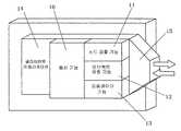
도 1a는 본 발명의 제1 실시예에 따른 네트워크 시스템의 개략도이며, 도 1b는 네트워크 시스템 내에 사용되는 센터 서버의 구성도이다.FIG. 1A is a schematic diagram of a network system according to a first embodiment of the present invention, and FIG. 1B is a configuration diagram of a center server used in the network system.
도 2a는 네트워크 시스템 내에 사용되는 클라이언트 단말 기기의 구성도이며, 도 2b는 클라이언트 단말 기기의 클라이언트 플랫폼의 구성도이다.2A is a configuration diagram of a client terminal device used in a network system, and FIG. 2B is a configuration diagram of a client platform of the client terminal device.
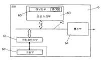
도 3a는 네트워크 시스템 내에 사용되는 장비의 구성도이며, 도 3b는 장비의 MOS의 구성도이다.3A is a configuration diagram of equipment used in a network system, and FIG. 3B is a configuration diagram of MOS of equipment.
도 4a 및 4b는 본 발명의 제2 실시예에 따른 네트워크 시스템의 동작예를 나타내는 설명도이다.4A and 4B are explanatory diagrams showing an example of the operation of the network system according to the second embodiment of the present invention.
도 5는 제2 실시예의 네트워크 시스템의 다른 동작예를 나타내는 설명도이다.5 is an explanatory diagram showing another operation example of the network system of the second embodiment.
본 발명의 네트워크 시스템은 바람직한 실시예들에 따라서 아래에서 상세히 설명된다.The network system of the present invention is described in detail below in accordance with preferred embodiments.
(제1 실시예)(First embodiment)
도 1a는 본 실시예의 네트워크 시스템의 구성을 나타내는 개략도이다. 이 네트워크 시스템은 주로 클라이언트 단말 기기(client terminal device)(2), 센터 서버(center server)(3), 게이트웨이(5), 및 다양한 종류의 장비(equipment)(6)들로 구성된다. 클라이언트 단말 기기(2)는 개방형 네트워크인 인터넷(1)에 연결된 퍼스널 컴퓨터 또는 인터넷(1)에 연결되는 모바일 통신 네트워크(mobile communication network)에서 사용되는 모바일 통신 단말 기기와 같은 네트워크 기기(network device)이다. 센터 서버(3)는 이하에 설명되는 바와 같이, 인터넷(1)에 연결되는 오브젝트 액세스 서버(object access server, 이하 "OAS"라 함)(7)의 기능을 갖는 네트워크 기기이다. 게이트웨이(5)는 사용자 영역 A 내의 로컬 영역 네트워크(local area network, LAN)(4) 및 인터넷(1) 사이에서 연결되며, 인터넷(1) 및 LAN(4) 사이의 프로토콜 변환 기능(protocol converting function)을 포함하는 상술한 OAS(7)의 기능을 갖는다. LAN(4)에 의하여 접속되는 장비들(6)(첨부된 도면에서 도시된 세 개의 장비들 6a 내지 6c)은 사용자 영역 A 내의 주택 또는 빌딩에 위치된다.Fig. 1A is a schematic diagram showing the configuration of the network system of this embodiment. This network system mainly consists of a
도 2a에 도시된 바와 같이, 클라이언트 단말 기기(2)는 네트워크 통신을 위한 통신부(20), 계산 처리부(arithmetic processing portion)(21), 키보드나 디스플레이와 같은 입력/출력부(22), 및 일시적으로 데이터를 저장하고 네트워크 시스템 및 클라이언트 어플리케이션(소프트웨어)에 의하여 제공되는 서비스들을 수신하기 위한 클라이언트 소프트웨어(오브젝트 액세스 라이브러리(Object Access Library, 이하 "OAL"이라 함))를 인스톨하기 위하여 사용되는 메모리부(23)를 포함한다. 계산 처리부(21)에서, 인터넷(1) 및 LAN(4) 상의 노드 검출(node detection)이 OAL의 실행에 의하여 수행된다. 또한, 계산 처리부(21)는 나중에 설명될 오브젝트에 액세스할 수 있고, 장비(6)에 의하여 제공되는 서비스가 클라이언트 단말 기기에 의하여 원하는 형태(desired form)로 수신될 수 있도록 클라이언트 어플리케이션을 실행한다. 또한, 클라이언트 단말 기기(2)는 이후에 설명될 오브젝트 식별자(object identifier)를 개별적으로 지정하도록 구성되는 식별자 지정부(identifier specifying portion)(26)를 갖는다. 입력/출력부(22)를 통한 서비스 요청 입력(service request input)에 따라서, 미리 정해진 오브젝트 식별자가 지정(선택)된다. 도 2a에서, 참조 번호 24는 버스(bus)를 가리킨다.As shown in FIG. 2A, the
본 실시예에서, 클라이언트 어플리케이션 및 OAL에 의하여 형성되는 클라이언트 플랫폼(client platform)은 도 2b에 도시된 구성을 갖는다. OAL은 클라이언트 어플리케이션(14)과 정보를 주고받기 위한 통신 기능(10), 네트워크 상에서 오브젝트를 갖는 장비를 검출하기 위한 노드 검출 기능(11), 오브젝트 요청 기능(12), 네트워크 접속을 위한 프로바이더 기능(provider function)(13), OAL 플랫폼에 대한 전송 조건(transmission condition)(15) 등을 갖는다.In this embodiment, the client platform formed by the client application and the OAL has the configuration shown in FIG. 2B. The OAL has a
반면에, 네트워크 시스템에 연결된 장비들(6)(6a 내지 6c)은 사용자 영역 A 내의 주택 또는 빌딩에 위치될 수 있다. 장비들이 빌딩에 위치되기 때문에, 환경 장비들(조명 또는 에어 컨디셔닝), 방범 장비(crime-prevention equipment), 방재 장비(disaster-prevention equipment), 및 이러한 장비들에 사용되는 온도 센서, 휘도(brightness) 센서, 인체 감지 센서, 및 화재 감지 센서(fire detection sensor)와 같은 센서 기기들이 있다. 또한 이들 장비가 주택 내에 위치될 수도 있다.On the other hand, the equipment 6 (6a to 6c) connected to the network system may be located in a house or building in the user area A. Because equipment is located in a building, environmental equipment (lighting or air conditioning), crime-prevention equipment, disaster-prevention equipment, and temperature sensors used in these equipment, brightness There are sensor devices such as sensors, human body sensors, and fire detection sensors. These equipment may also be located in the house.
도 3a에 도시된 바와 같이, 이러한 장비들(6) 각각은 기본적으로 장비(6)에 고유한 서비스를 제공하기 위한 기능부(60), 정보 처리부(63), 네트워크 통신을 위한 통신부(64) 및 정보 처리부(63) 내에 제공되는 메모리부(65)로 구성된다. 예를 들어, 장비가 에어컨일 경우에, 기능부(60)는 에어 컨디셔닝 기기 및 에어 컨디셔닝을 제어하기 위한 제어 기기에 대응한다. 장비가 조명 장비일 경우에, 기능부(60)는 조명을 제어하기 위한 조명 기기에 대응한다. 장비가 상술한 센서 기기인 경우에, 기능부(60)는 감지를 위한 헤더(header) 및 헤더에 의하여 감지된 감지 정보를 출력하기 위한 신호 처리 유닛에 대응한다. 정보 처리부(63)는 인터페이스부(61) 및 버스(62)를 통하여 기능부(60)로 동작 명령(operation instruction)(동작 제어) 함수를 제공하거나, 기능부(60)의 현재 상태를 나타내는 변수를 획득하거나, 기능부(60)의 상태 변화의 발생을 나타내는 이벤트 정보를 획득하도록 구성된다. 메모리부(65)에서, 소프트웨어 모듈(이하 "MOS"<Micro Object Server>라 함)이 본 실시예의 네트워크 시스템 내에서 오브젝트 서버 기능을 달성하기 위하여 인스톨된다.As shown in FIG. 3A, each of these
도 3b에 도시된 바와 같이, MOS는 서비스를 제공하기 위한 프로그램 모듈인 오브젝트를 포함하는 어플리케이션 섹션(40)과, 이후 설명될 OSI 7-계층의 프로토콜(OSI 7-layer protocol)에 대응하는 소프트웨어 통신 모듈(41)과, 통신부(64) 및 인터페이스부(61)와 통신하도록 구성되는 하드웨어 통신 모듈(42)로 구성된다.As shown in FIG. 3B, the MOS is a software section corresponding to an OSI 7-layer protocol and an
본 실시예에서, OSI 7-계층 모델은 네트워크 시스템을 위한 프로토콜로서 사용된다. 최상위 계층의 어플리케이션 계층으로서, 고유한 오브젝트 액세스 프로토콜(object access protocol, OAP)이 장비(6)의 정보 처리부(63)의 MOS와 클라이언트 단말 기기(2) 사이에서 변수, 함수 및 이벤트 정보와 같은 정보를 주고받기 위하여 사용된다.In this embodiment, the OSI 7-layer model is used as the protocol for the network system. As the application layer of the highest layer, a unique object access protocol (OAP) allows information such as variable, function, and event information between the MOS of the
MOS의 소프트웨어 통신 모듈(41)은 TCPUDP의 통합 및 상술한 OAP의 정의(definition)를 수행하기 위하여, OSI 7-계층 모델의 네트워크 계층(network layer)에서 프리젠테이션 계층(presentation layer)까지의 프로토콜에 대한 책임을 진다.The
장비(6)의 각각은, 정보 처리부(63)의 MOS 내에 기능부(60)가 서비스를 제공하기 위한 처리를 수행할 때 사용되는, 적어도 하나의 오브젝트를 갖는다. 또한,오브젝트는 제공되는 서비스에 대응하는 변수, 함수 및 이벤트 정보와 같은 정보에 의하여 정의되는 적어도 하나의 인터페이스를 갖는다. 고유 식별자(이하 "OID"라 함)가 오브젝트에 할당되며, 인터페이스 식별자(interface identifier)(또는 이후에 "IID"로 언급되는 입력/출력 정의 식별자(input/output definition identifier))가 인터페이스에 할당된다. 동일한 정의 내용, 즉 동일한 IID를 갖는 인터페이스는 복수의 오브젝트들에 할당될 수 있다. 특정한 장비(6)를 지정할 필요가 없는 서비스의 경우에, 동일한 OID가 복수의 장비들(6)의 오브젝트들에 할당될 수도 있다.Each of the
또한, 상술한 바와 같이, 클라이언트 단말 기기(2)의 OAL은 장비(6)의 오브젝트의 IID/OID를 지정하여 서비스 요청(service request)을 수행할 수 있다. 이 경우에, 클라이언트 단말 기기(2)는 노드 검출 기능(11)을 사용하여 장비(6)의 IP 어드레스, 오브젝트의 OID 및 인터페이스의 IID를 획득하며, 장비들의 IID/OID 및 IP 어드레스 사이의 대응 테이블(correspondence table)을 준비한다.In addition, as described above, the OAL of the
다음에, 도 1a에 도시된 OAS(7)를 사용한 시스템에서 클라이언트 단말 기기(2)가 시스템 내의 오브젝트의 OID 및 인터페이스의 IID를 사용하여 장비의 오브젝트에 액세스하는 경우를 설명한다.Next, the case where the
게이트웨이(5) 및 센터 서버(3) 내에 인스톨되는 전술한 OAS(7)는 네트워크 접속(network connection)을 숨기기 위한 오브젝트 라우터 기능(object router function)을 제공하는 소프트웨어, 사용자(클라이언트 단말 기기(2))가 장비(6)의 오브젝트 하에서 입력/출력 정의 기능(즉, 인터페이스)을 액세스함에 의하여 장비(6)의 기능부(60)에 의하여 제공되는 서비스를 받을 수 있도록 허용하도록 실행되는 다양한 응용 소프트웨어들, 및 프로토콜 변환을 통하여 본 실시예의 네트워크 시스템으로의 심리스 접속(seamless connection)을 위한 프로토콜 브릿지 서비스 및 방화벽을 통하여 통과하도록 OAS-7 계층 모델 내의 프로토콜을 SOAP로 변환하기 위한 방화벽 브릿지 서비스와 같은 부가 서비스 기능들을 제공하는 소프트웨어들로 구성된다.The above-described
장비(6)의 특정 오브젝트의 인터페이스에 액세스하는 경우에 있어서, 클라이언트 단말 기기(2)의 서비스 요청은 센터 서버(3)를 통하여 OAP에 의하여 대응하는 장비(6)에 대하여 수행된다. 이때, IP 어드레스는 인터넷 통신상의 장비(6)를 식별하기 위하여 사용된다. 따라서 장비들(6) 각각은 IP 어드레스를 갖는다.In the case of accessing the interface of a specific object of the
게이트웨이(5)의 OAS(7)는 프로토콜 변환 기능(protocol conversion function) 및 라우팅 기능을 갖는다. 라우팅 기능은 게이트웨이(5)의 CPU부(도시하지 않음) 내의 소프트웨어를 실행함에 의하여 제공된다. 라우팅 기능은 LAN(4)에 연결되는 장비들(6) 각각의 인터페이스의 IID 및 MOS 내의 오브젝트의 OID에 대한 조합 정보(combination information)와 장비들(6)(6a, 6b, 6c) 각각의 IP 어드레스 사이의 대응 관계를 나타내는 라우팅 테이블(routing table)을 준비하는 기능 및 라우팅 처리를 실행하는 기능을 포함한다. 초기 기동(activation)에 있어서, 네트워크에 접속되는 장비들(6)(6a, 6b, 6c)은 OAP의 사용과 함께 멀티캐스팅(multicasting) 수단들에 의하여 독출되며, 노드 검출이 IP 어드레스를 획득하기 위한 응답(response)의 존재 또는 부존재에 따라서 수행된다. 이어서, 전술한 라우팅 테이블(접속 장비 정보 테이블)이 IP 어드레스와 MOS의 오브젝트의 OID 및 장비들(6a, 6b, 6c) 각각으로부터 제공되는 오브젝트 하의 인터페이스의 IID에 대한 조합 정보의 사용에 의하여 게이트웨이에서 준비된다. 이후, 조합 정보 및 게이트웨이의 IP 어드레스는 인터넷(1) 상의 서버, 즉 도 1a에서의 센터 서버(3)로 전송된다.The
반면에, 도 1b에 도시된 바와 같이, 센터 서버(3)는 네트워크 통신을 위한 통신부(30) 및 소프트웨어의 실행에 의하여 OAS(7)를 실현하기 위한 계산 처리부(31)를 포함하는 컴퓨터 시스템에 의하여 구성된다. 센터 서버(3)의 OAS(7)는 게이트웨이(5)로부터 제공되는 게이트웨이(5)의 IP 어드레스 및 장비들(6)의 IID 및 OID에 대한 조합 정보 사이의 대응 관계를 나타내는 라우팅 테이블(접속 OAS 정보 테이블)을 준비하며, 라우팅 처리를 실행하는 라우팅 기능부(31c)를 갖는다. 또한, 센터 서버(3)는 그 자신의 오브젝트에 대한 IID 및 OID의 조합 정보를 인터넷(1)을 통하여 연결된 클라이언트 단말 기기(2)로 제공한다.On the other hand, as shown in FIG. 1B, the
다음에, 본 실시예의 네트워크 시스템의 동작이 설명된다. 사용자 영역 A 내에서, 시스템이 기동되었을 때, 게이트웨이(5)의 OAS(7)는 우선 멀티캐스팅 방식으로 LAN(4)에 연결된 장비들(6)(6a, 6b, 6c) 각각에 액세스하며, 이후 장비들(6)(6a, 6b, 6c) 각각으로부터의 응답에 따라 IP 어드레스를 획득한다.Next, the operation of the network system of the present embodiment will be described. Within user area A, when the system is started up, the
이어서, 정보 처리부(63)의 MOS의 오브젝트의 OID 및 이 오브젝트 아래의 인터페이스의 IID로 이루어지는 조합 정보는 장비들(6)(6a, 6b, 6c) 각각으로부터 게이트웨이(5)로 전송된다. 게이트웨이(5)의 OAS(7)는 OID 및 IID의 조합 정보 및 장비들 각각에 대한 IP 어드레스를 갖는 라우팅 테이블을 준비한다. 또한, 게이트웨이(5)는 LAN(4)에 접속된 장비들(6)(6a, 6b, 6c) 각각의 (OID 및 IID의) 조합 정보 및 게이트웨이(5)의 글로벌 IP 주소 정보(global IP address information)를 인터넷(1)상의 OAS(7), 즉 도 1a에 도시된 센터 서버(3)의 OAS(7)로 전송한다.Subsequently, the combination information consisting of the OID of the object of the MOS of the
센터 서버(3)의 OAS(7)에 있어서, 라우팅 테이블은 게이트웨이(5)에 의하여 관리되는 장비들(6)(6a, 6b, 6c)의 인터페이스에 대한 IID 및 오브젝트에 대한 OID의 조합 정보 및 게이트웨이(5)의 IP 어드레스로부터 마련된다. 또한, 이러한 라우팅 테이블 내에 저장되어 있는 장비들(6)(6a, 6b, 6c)의 인터페이스에 대한 IID 및 오브젝트에 대한 OID는 센터 서버(3)로부터 클라이언트 단말 기기(2)의 OAL로 전송되며, 이 후 거기에 저장된다. 결과적으로, 클라이언트 단말 기기(2)는 이러한 OID 및 IID의 사용에 의하여 제공되는 서비스에 대한 실행 요청을 수행할 수 있다.In the
클라이언트 단말 기기(2)에 있어서, 오브젝트 식별자(즉, OID, IID)의 사용에 의하여 장비들(6)에 대하여 서비스 제공을 요청하는 동작을 수행하기 위하여 서비스 요청을 위한 어플리케이션이 런칭(launch)되는 경우에, 요청된 서비스 내용에 대응하는 정보를 정의하는 인터페이스를 갖는 모든 오브젝트(들)의 IID 또는 OID, 또는 특정 오브젝트에 대한 OID와 그 오브젝트 아래의 특정한 인터페이스의 IID와의 조합 정보가 OAP에 의하여 인터넷(1)을 경유하여 센터 서버(3)로 서비스 요청으로서 전송된다.In the
센터 서버(3)의 OAS(7)가 클라이언트 단말 기기(2)로부터 서비스 요청으로서, 장비(들)(6)의 오브젝트(들)에 대한 IID 또는 OID, 또는 IID 및 OID에 대한 조합 정보를 수신한 후에, 이들은 IID, OID 또는 IID 및 OID의 조합 정보에 대응하는 장비들(6)(6a, 6b, 6c)이 LAN(4)을 통하여 접속되도록 하는 게이트웨이(5)를 추출하기 위하여, 센터 서버의 라우팅 테이블 내에 저장된 정보에 대응하여 체크된다. 이 후, 센터 서버(3)는 클라이언트 단말 기기(2)로부터 제공된 IID, OID 또는 IID 및 OID에 대한 조합 정보를 갖는 서비스 요청을 추출된 게이트웨이(5)로 전송한다.The
게이트웨이(5)의 OAS(7)가 이 서비스 요청을 수신한 후, 접속 장비 정보 테이블의 내용에 따라서 LAN(4)을 통하여 연결되며 게이트웨이(5)에 의하여 관리되는 대응하는 장비(들)를 추출하며, 센터 서버(3)로부터 수신된 IID, OID 또는 IID 및 OID에 대한 조합 정보를 갖는 서비스 요청을 추출된 장비(들)(6)에 전송한다.After the
즉, OID만을 사용하여 서비스 요청을 수행하는 경우에, 게이트웨이(5)는 이 OID를 갖는 서비스 요청을 이 OID가 할당된 오브젝트를 갖는 모든 장비(들)(6)로 전송한다. 결과적으로, 장비(들)(6)의 정보 처리부(63)는 이 OID에 대응하는 오브젝트를 실행하며, 따라서 이 오브젝트 아래의 인터페이스(들)에 의하여 정의되는 정보(함수, 변수, 이벤트 정보)는 정보 처리부(63) 및 기능부(60) 사이에서 교환되게 된다. 동일한 OID가 복수의 장비들(6)의 오브젝트들에 할당되는 경우에, 동일한 서비스가 이들 장비(6)로부터 제공될 수 있다.That is, in the case of performing a service request using only the OID, the
또한, IID만을 사용하여 서비스 요청을 수행하는 경우에, 게이트웨이(5)의 OAS(7)는 이 IID를 갖는 서비스 요청을 이 IID가 할당된 인터페이스의 오브젝트를 갖는 모든 장비(들)로 전송한다. 결과적으로, 장비(들)(6)의 정보 처리부(63)는 이 IID에 대응하는 인터페이스의 오브젝트를 실행하며, 따라서 이 오브젝트 아래의 인터페이스에 의하여 정의되는 정보(함수, 변수, 이벤트 정보)는 정보 처리부(63) 및 기능부(60) 사이에서 교환되게 된다. 동일한 IID가 복수의 장비들(6)의 오브젝트들의 인터페이스들에 할당되는 경우에, 동일한 정의 내용의 정보를 기반으로 하는 서비스가 장비들로부터 제공될 수 있다.In addition, when performing a service request using only the IID, the
또한, OID 및 IID의 조합 정보를 사용하여 서비스 요청을 수행하는 경우에, 게이트웨이(5)의 OAS(7)는 IID 및 OID의 조합 정보를 갖는 서비스 요청을 이 OID가 할당된 오브젝트 및 IID가 할당된 인터페이스를 갖는 장비로 전송한다. 결과적으 로, 장비(6)의 정보 처리부(63)는 이 OID에 대응하는 인터페이스를 갖는 오브젝트를 실행하며, 따라서 이 오브젝트 아래의 인터페이스에 의하여 정의되는 정보는 정보 처리부(63) 및 기능부(60) 사이에서 교환되게 된다. 이 경우에, 특정 장비(6)의 오브젝트의 인터페이스에 의하여 정의된 정보를 기반으로 하는 서비스가 이 장비(6)로부터 제공될 수 있다.In addition, when performing a service request using the combination information of the OID and the IID, the
서비스 요청이 함수를 정의하는 인터페이스에 대하여 수행되는 경우에, 정보는 장비(6)로부터 클라이언트 단말 기기(2)로 전달되지 않는다. 서비스 요청이 변수를 정의하는 인터페이스에 대하여 수행되는 경우에, 즉 장비(들)의 현재 상태에 대한 정보가 요청되는 경우에, 정보는 장비(6)로부터 게이트웨이(5)로 전송되며, 게이트웨이의 OAS(7)는 정보를 센터 서버(3)로 전송하며, 최종적으로 센터 서버(3)의 OAS(7)는 정보를 클라이언트 단말 기기(2)로 전송한다.In the case where a service request is performed on an interface defining a function, information is not passed from the
또한, 이벤트 정보를 정의하는 인터페이스에 대하여 수행되는 서비스 요청에 관하여, 정보 처리부(63)가 장비(6)의 기능부(60)에서 이벤트가 발생한 사실을 나타내는 이벤트 정보를 수신하는 경우에, 이벤트 정보는 장비(6)로부터 게이트웨이(5)로 전송되며, 게이트웨이(5)의 OAS(7)는 이벤트 정보를 센터 서버(3)로 전송하며, 마지막으로 센터 서버(3)의 OAS(7)는 이벤트 정보를 클라이언트 단말 기기(2)로 전송한다.Further, with respect to the service request performed on the interface defining the event information, when the
따라서, 본 실시예의 네트워크 시스템에 따르면, 클라이언트 단말 기기(2)가 장비(들)(6)의 인터페이스의 IID 또는 오브젝트의 OID의 사용에 의하여 서비스 요청을 수행하는 경우에, 센터 서버(3)의 OAS의 라우팅 기능의 도움에 의하여 LAN(4) 을 통하여 게이트웨이(5)에 연결되는 장비(들)의 오브젝트(들)에 액세스하는 것이 가능하게 된다. 따라서 클라이언트 단말 기기(2)는 장비(들)(6)의 IP 어드레스를 고려하지 않고도 장비(들)(6)에 의하여 제공되는 서비스를 받을 수 있다.Therefore, according to the network system of the present embodiment, when the
또한, 제공되는 서비스들의 수를 증가시키기 위하여 추가적인 장비(들)(6)가 새로이 네트워크 시스템에 접속되는 경우조차도, 추가적인 장비(들)(6)의 MOS의 IID 및 OID가 전술한 바와 같이 클라이언트 단말 기기(2)에 전송된다. 따라서 단순히 추가적인 장비(들)(6)의 MOS의 인터페이스의 IID 및 오브젝트의 OID에 관하여, 서비스 요청을 수행하기 위한 어플리케이션을 변경하거나 업데이팅하는 것에 의하여, 클라이언트 단말 기기(2)는 추가적인 장비(들)(6)에 의하여 제공되는 서비스를 받을 수 있다.In addition, even if the additional equipment (s) 6 are newly connected to the network system to increase the number of services provided, the IID and OID of the MOS of the additional equipment (s) 6 are as described above. Is sent to the
센터 서버(3)는 전술한 OAS(7) 이외에 클라이언트 단말 기기(2) 내에 인스톨되는 브라우저로 열람 가능한 웹 사이트를 만들기 위한 웹 서버 기능을 가질 수 있다. 이 경우에, 센터 서버(3)에 의하여 수집되는 정보가 클라이언트 단말 기기(2)로부터 언제라도 열람 가능하게 되는 이점이 있다.The
(제2 실시예)(2nd Example)
본 실시예는 상술한 라우팅 기능에 덧붙여 아래의 기능들을 갖는 것을 특징으로 한다. 즉, 센터 서버(3)의 OAS(7) 상에서, 장비(6)의 오브젝트 하의 인터페이스 정보에 대한 정의 내용은 임의의 IID가 할당되는 적어도 하나의 인터페이스를 갖는 적어도 하나의 오브젝트를 획득하기 위하여 재정의된다. 클라이언트 단말 기기(2)가 OID 및 IID의 사용에 의하여 이 OAS(7) 상의 서버측 오브젝트 및 인터페이 스에 액세스하는 경우, 센터 서버(3)는 그 OID 및 IID의 사용에 의하여 이전에 관련지어져 있는 장비(6)의 장비측 오브젝트 및 인터페이스에 액세스한다. 따라서, 사용자는 클라이언트 단말 기기(2)로부터 센터 서버(3)의 OAS(7) 상의 오브젝트 하의 인터페이스의 IID를 액세스함으로써, 장비(들)(6)에 의하여 제공되는 서비스를 요청할 수 있다.This embodiment has the following functions in addition to the above-described routing function. That is, on the
다음으로, 클라이언트 단말 기기(2)가 센터 서버(3)의 OAS의 오브젝트에 액세스하는 경우에 대하여 설명된다. 본 실시예를 달성하기 위하여, 도 1b에 도시된 바와 같이, 센터 서버는 서비스 요청 기능부(31a) 및 서비스 제공 기능부(31b)를 가질 필요가 있다.Next, the case where the
즉, 센터 서버(3)의 OAS는 장비(들)(6)의 정보 처리부(63) 내의 MOS의 오브젝트의 식별자인 OID, 오브젝트 하의 인터페이스의 IID 또는 OID 및 IID의 조합 정보의 사용에 의하여 게이트웨이(5)를 통하여, 장비(들)(6)로 오브젝트의 인터페이스에 의하여 정의되는 정보를 주고받는 서비스 요청으로서의, 요청을 수행하기 위하여 구성되는 서비스 요청 기능부(31a)를 가지며, 게이트웨이(5)를 통하여 장비(들)(6)와 요청된 서비스에 대응하는 정보를 주고받는다. 또한, 센터 서버(3)의 OAS의 서비스 제공 기능부(31b)는 클라이언트가 서비스를 수신할 수 있도록, 즉 클라이언트에게 제공되는 서비스를 위하여 사용되는 정보를 정의하는 인터페이스를 갖는다. 인터페이스의 정의에 따라서, 요청된 서비스의 정보가 서비스 제공 기능부(31b) 및 서비스 요청 기능부(31a) 사이에서 교환되게 된다. 또한, 서비스 제공 기능부(31b)는 정의에 따라서 요청된 서비스의 정보와 클라이언트가 서비스를 받기 위하여 사용되는 정보 사이의 변환을 실행하기 위한 서버측 오브젝트(server-side object)를 갖는다. OID가 서버측 오브젝트에 할당되며, 임의의 IID가 이 오브젝트 하의 인터페이스에 할당된다. 따라서, 서비스 제공 기능부(31b)가 클라이언트 단말 기기(2)로부터 오브젝트에 대한 고유 식별자, 오브젝트 하의 인터페이스의 IID 또는 OID 및 IID의 조합을 사용하여 오브젝트에 대한 실행 요청을 수신하면, 서비스 제공 기능부(31b)는 대응하는 오브젝트를 실행한다. 전술한 "변환"의 의미는, 예를 들어 "현재 온도"가 "주어진 시간 길이에 대한 평균 온도"로 변환되는 것처럼, 특정 정보가 다른 의미를 갖는 정보로 변화되는 것을 의미한다.That is, the OAS of the
본 실시예에 있어서, 장비측 오브젝트를 추가하거나, 장비측 오브젝트 내의 정보 정의를 변경하지 않고, 센터 서버(3)의 서버측 오브젝트에 의하여 새로운 서비스를 제공할 수 있다. 또한 장비(들)가 추가되는 경우조차도, 존재하는 장비들(6)에 관계없이 제공되는 서비스들의 종류를 용이하게 확장할 수 있다.In this embodiment, a new service can be provided by the server side object of the
다음으로, 본 실시예의 네트워크 시스템의 동작은 구체적 예시에 따라서 설명된다. 아래의 예시에 있어서, 서버측 오브젝트들 각각에 할당되는 식별자들(OID, IID) 및 장비측 오브젝트들 각각에 할당되는 식별자들(OID, IID) 사이의 대응 관계는 센터 서버(3)의 식별자 설정부(identifier setting portion) 내에서 설정된다.Next, the operation of the network system of the present embodiment is described according to a specific example. In the example below, the correspondence between the identifiers OID and IID assigned to each of the server-side objects and the identifiers OID and IID assigned to each of the equipment-side objects is set by the identifier of the
도 1a의 장비(6)(6a, 6b, 6c)의 기능부(60)가 도 4a에 도시된 바와 같이 온도 센서이며, 온도 센서에 의하여 제공되는 서비스에 대응하는 정보가 "현재 온도"의 명칭을 갖는 변수로서 정의되는 조건 하에서, 장비(6)(6a, 6b, 6c) 각각의 정보 처리부(63)의 오브젝트(OID: xxa, xxb, xxc) 하의 인터페이스의 IID는 "온도 센서"로 설정되는데, 왜냐하면 정의 내용이 동일하기 때문이다.The
센터 서버(3)에 있어서, OAS(7) 상의 서비스 요청 기능부(31a)는 IID "온도 센서"가 할당되는 인터페이스를 갖는 오브젝트의 OID에 주기적으로 액세스하여, 그 액세스의 결과로서 장비(6)(6a, 6b, 6c)로부터 제공되는 "현재 온도"의 변수를 기록하도록 프로그램되는 온도 모니터링 서비스에 대응하는 어플리케이션에 의하여 실현된다. 이 어플리케이션에 대응되어 있는 OID "yyy"를 갖는 오브젝트 하의 인터페이스의 IID "zzz"가 클라이언트 단말 기기(2)에 의하여 액세스되는 경우에, 이 어플리케이션은 MOS 내의 IID "온도 센서"의 인터페이스를 갖는 오브젝트를 갖는 장비(6)(6a, 6b, 6c)에 LAN(4)을 통하여 접속되는 게이트웨이(5)를, 라우팅 테이블을 참조하여 추출하며, 이후 추출된 게이트웨이(5)로 IID "온도 센서"가 할당된 인터페이스를 갖는 오브젝트에 대한 서비스 요청을 전송하도록 런칭된다.In the
반면에, 서비스 요청을 수신한 게이트웨이(5)의 OAS(7)는, 접속 장비 정보 테이블을 참조하여, IID "온도 센서"가 할당되는 인터페이스를 갖는 오브젝트를 가지며 LAN(4)을 통하여 게이트웨이(5)에 연결되는 장비(6)(6a, 6b, 6c)를 추출하며, 이후 추출된 장비(들)(6)에 대하여 주기적으로 서비스 요청을 수행한다.On the other hand, the
서비스 요청을 수신한 장비(6)의 정보 처리부(63)는 온도 센서인 기능부(60)에 의하여 검출된 현재 온도 정보를 획득하며, 이를 변수 "현재 온도"로서 게이트웨이(5)로 전송한다. 이후 게이트웨이(5)의 OAS(7)에 의하여 수신되는 변수 "현재 온도"는 센터 서버(3)로 전송된다. 센터 서버(3)의 OAS(7) 상의 서비스 제공 기능 부(31b)를 실현하는 어플리케이션에 의하여, 변수 "현재 온도"는 서비스 요청이 수행되는 클라이언트 단말 기기(2)로 전송된다. 따라서, 사용자는 클라이언트 단말 기기(2)의 사용에 의하여 원격지로부터 가정 또는 빌딩 내의 현재 온도 및 온도 변화에 대한 정보를 임의로 획득할 수 있다.The
예를 들어, 장비들(6b, 6c) 각각이 장비(6a)의 오브젝트 하에서의 인터페이스로서 동일한 IID가 할당된 인터페이스를 갖는 오브젝트를 가지는 경우에, 변수 "현재 온도"는 장비(6a)에 덧붙여 장비들(6b, 6c)로부터의 서비스로서 제공될 수 있다.For example, if each of the
또한 장비들(6a, 6b)이 이전에 위치되며, 장비(6c)가 추가적으로 위치되는 경우에 있어서, 장비(6c)는 장비들(6a, 6b)과 다른 IP 어드레스를 갖는다. 반면에, 장비(6c)의 오브젝트의 OID 및 상기 오브젝트 하의 인터페이스의 IID는 게이트웨이(5)의 OAS(7)의 라우팅 테이블(접속 OAS 정보 테이블) 내에 저장된다. 또한, LAN(4)을 경유하여 대응하는 장비(6c)에 연결되는 게이트웨이(5)의 IID, OID 및 IP 어드레스는 센터 서버(3)의 OAS(7)의 라우팅 테이블에 추가된다. 그러나, 센터 서버(3)의 OAS(7) 상의 어플리케이션이 장비(6c)의 오브젝트 하에서 IID "온도 센서"가 할당된 인터페이스를 액세스하기 위한 서비스 요청을 추가되는 장비(6c)의 IP 어드레스를 직접적으로 고려할 필요없이 클라이언트 단말 기기(2)로부터의 서비스 요청에 따라서 게이트웨이(5)를 통하여 전송할 수 있기 때문에, 간단하고 유연하게 시스템 변경에 대처할 수 있다.Also, in the case where
다음으로, 본 실시예의 네트워크 시스템의 다른 동작이 아래 예시에 따라서 도입된다. 전술한 경우에 있어서, 장비(6)(6a, 6b, 6c) 각각에 관련하여, 기능부(60)가 온도 센서에 의하여 제공되며, 정보 처리부(63)는 상기 오브젝트 하에서 IID "온도 센서"가 할당되는 인터페이스를 가진다. 본 예시에서, 도 4b에 도시된 바와 같이, 장비들(6)(6a, 6b, 6c) 각각에 관하여, 기능부(60)가 인체 감지 센서에 의하여 제공되며, 정보 처리부(63)은 오브젝트 하에서 IID "인체 감지 센서"가 할당된 인터페이스를 갖는다. 따라서 본 예시는 인체 감지 센서가 인체의 존재를 탐지했다는 점을 나타내는 이벤트 정보를 통지하는 서비스를 제공한다.Next, another operation of the network system of the present embodiment is introduced according to the example below. In the case described above, with respect to each of the equipment 6 (6a, 6b, 6c), a
따라서, 이 경우에, 오브젝트 하에서 인터페이스 내에서 정의된 정보는 "존재 감지(existence detection)"라는 명칭의 이벤트 정보이며, "인체 감지 센서"가 IID로서 할당된다.Thus, in this case, the information defined in the interface under the object is event information named "existence detection", and "human detection sensor" is assigned as the IID.
장비들(6)(6a, 6b, 6c)의 MOS는 기능부(60)로부터 이벤트 정보를 수신하기 위한 처리를 실행한다. 이벤트 정보가 각 장비들(6)로부터 게이트웨이(5)를 통하여 전송되는 경우에, 센터 서버(3) 상의 OAS(7)의 어플리케이션으로서 방범 서비스 어플리케이션은 이벤트 정보를 휴대 전화(mobile-phone)와 같은 클라이언트 단말 기기(2)로 전송한다. 따라서, 이러한 어플리케이션에 관련된 오브젝트의 OID 및 이 오브젝트 하의 인터페이스의 IID "인체 감지 센서"는 클라이언트 단말 기기(2)로부터 액세스되며, 정보 처리부(63) 내에서 상술한 라우팅 테이블(즉, 접속 OAS 정보 테이블)의 사용에 의하여 이 어플리케이션은 클라이언트 단말 기기(2)로서 사용되는 휴대 전화의 메일 어드레스(mail address)를 추출하며, IID "인체 감지 센서"가 할당된 인터페이스를 갖는 오브젝트를 갖는 장비(6)(6a, 6b, 6c)에 LAN(4)을 통하여 연결되는 게이트웨이(5)를 추출하기 위한 처리를 수행하기 위하여 런칭된다. 결과적으로, IID "인체 감지 센서"가 할당된 인터페이스를 갖는 오브젝트로의 서비스 요청은 추출된 게이트웨이(5)로 전송된다.The MOS of the devices 6 (6a, 6b, 6c) executes a process for receiving event information from the
서비스 요청에 응답하여, 게이트웨이(5)의 OAS(7)는 접속 장비 정보 테이블의 사용에 의하여 LAN(4)에 연결되는 대응하는 장비(들)(6)(6a, 6b, 6c)을 추출하며, 추출된 장비(들)(6)로 서비스 요청을 전송한다. 추출된 장비(들)(6)의 정보 처리부(63) 내에서, 대응하는 오브젝트가 실행된다. 기능부(60)가 인체의 존재를 감지하는 경우에, 상태 변화(status change) 즉, "존재 감지"를 나타내는 이벤트 정보가 게이트웨이(5)의 OAS(7)로 전송된다. 게이트웨이(5)에 의하여 수신된 이벤트 정보는 센터 서버(3)로 더 전송된다.In response to the service request, the
"존재 감지"의 이벤트 정보가 장비들(6)(6a, 6b, 6c) 중 어느 하나로부터 게이트웨이(5)를 통하여 전송되면, 센터 서버(3)의 OAS(7)는 "존재 감지"의 이벤트 정보를 클라이언트 단말 기기(2)로 통지한다. 예를 들어, 장비들(6b, 6c) 각각이 장비(6a)의 오브젝트 하에서의 인터페이스로서 동일한 IID가 할당된 인터페이스를 갖는 오브젝트를 가지는 경우에, 서비스로서 장비(6a) 뿐만 아니라 장비들(6b, 6c)로부터 "존재 감지"의 이벤트 정보를 수신하는 것이 가능하다.When the event information of "presence detection" is transmitted through the
상기의 예시와 마찬가지로, 본 예시에 있어서도, 이벤트 정보는 센터 서버(3)의 OAS(7) 상의 어플리케이션을 변경하지 않고, 추가되는 장비(6c)에서의 이벤트 발생에 응답하여 클라이언트 단말 기기(2)로 통지될 수 있다. 따라서, 간단하고 유연하게 시스템 변경에 대처할 수 있게 된다.Similar to the above example, also in this example, the event information does not change the application on the
다음으로, 본 실시예의 네트워크 시스템의 또 다른 동작이 아래의 예시에 따라서 도입된다. 전술한 예시에 있어서, 장비들(6)(6a, 6b, 6c) 각각의 정보 처리부(63)는 동일한 IID가 할당되는 하나의 인터페이스를 갖는 하나의 오브젝트를 가진다. 본 예시에 있어서, 하나의 오브젝트는 복수의 인터페이스들을 가지며, 제공되는 서비스 내용에 대응하는 IID들은 이 인터페이스들에 할당된다. 또한, 동일한 IID가 장비들(6)(6a, 6b, 6c) 중 동일한 정의 내용을 갖는 인터페이스들에 할당된다. 따라서, 사용자는 기능부(60)로부터 다양한 서비스들을 받을 수 있다.Next, another operation of the network system of the present embodiment is introduced according to the example below. In the above example, the
예를 들어, 장비들(6)(6a, 6b, 6c) 각각의 기능부(60)가 인체 존재의 감지 정보를 제공하는 기능을 가지는 인체 감지 센서에 의하여 제공되는 경우에, 전술한 바와 같이 이벤트 발생을 나타내는 이벤트 정보 또는 사용자의 요청에 따라 정보(함수)를 제공하는 것이 가능하다. 따라서, 서비스의 다양화는 서비스 내용 및 정보 정의의 조합에 따라서 인터페이스에 적당한 IID를 설정하는 것에 의하여 달성될 수 있다.For example, if the
즉, 도 5에 도시된 바와 같이, "안전 서비스(safety service)", "보안 서비스(security service)", "로컬 서비스(local service)", 및 "메이커 서비스(maker service)"와 같은 IID들을 갖는 복수의 인터페이스들이 준비된다. 본 설명에서, IID "메이커 서비스"는 모든 장비들(6)(6a, 6b, 6c) 내의 MOS의 오브젝트 하의 인터페이스에 할당되며, "응답"이라는 함수는 인터페이스 내에서 정의된다. 또한, IID "안전 서비스"는 실내 영역(indoor area)에 위치하는 장비들(6a, 6c) 각각의 MOS의 오브젝트 하에서의 인터페이스에 할당되며, "존재 감지(existence detection)"의 이벤트 정보는 상기 인터페이스 내에서 정의된다. 또한 IID "보안 서비스"는 주택의 현관에 위치된 장비(6a) 내의 MOS의 오브젝트 하의 인터페이스에 할당되며, IID들 "로컬 서비스" 및 "보안 서비스"는 주택 주변에 위치하는 장비(6b) 내의 MOS의 오브젝트 하에서의 인터페이스에 할당되며, "존재 감지"의 이벤트 정보는 상기 인터페이스들 내에서 정의된다. 따라서 서로 다른 종류의 서비스들이 장비들(6)(6a, 6b, 6c) 각각에 대하여 설정된다.That is, as shown in FIG. 5, IIDs such as "safety service", "security service", "local service", and "maker service" are provided. A plurality of interfaces are prepared. In this description, an IID "maker service" is assigned to an interface under the object of the MOS in all devices 6 (6a, 6b, 6c), and a function called "response" is defined within the interface. In addition, an IID "safety service" is assigned to an interface under the object of the MOS of each of the
반면에, IID를 갖는 인터페이스에 대응하는 서비스를 제공하기 위한 어플리케이션으로서, 센서 서버(3)의 OAS(7)가 클라이언트 단말 기기(2)로부터, 오브젝트의 OID "yyy" 하에서의 "존재 감지"의 이벤트 정보를 정의하는 인터페이스의 IID(예를 들어, 장비들(6a, 6c)의 "안전 서비스", 장비들(6a, 6b)의 "보안 서비스" 또는 장비(6b)의 "로컬 서비스")를 액세스하는 서비스 요청을 수신하는 경우에, 센터 서버(3)는 IID "안전 서비스", "보안 서비스" 또는 "로컬 서비스"를 갖는 인터페이스를 액세스하는 서비스 요청을 게이트웨이(5)를 통하여 대응하는 장비(들)(6a, 6b, 6c)로 전송한다. 이어서, 인체 감지 센서에 의하여 검출되는 정보에서 변화가 발생하면, 인체의 존재 또는 부존재를 지칭하는 "존재 감지"의 이벤트 정보가 게이트웨이(5)로 전송된다. 이후 상기 이벤트 정보는 대응하는 클라이언트 단말 기기(2)로 전송된다.On the other hand, as an application for providing a service corresponding to an interface having an IID, the
예를 들어, "안전 서비스"의 경우에 있어서, 독거 노인의 행동(behavior)이 실내에 위치하는 장비들(6a, 6c)의 인체 감지 센서들에 의하여 감지될 수 있다. 인간의 존재가 자주 감지되는 경우에, 재택 노인의 가족과 같은 사용자가 클라이언 트 단말 기기(2)를 통하여 독거 노인의 상태에 대한 정보를 획득할 수 있다.For example, in the case of "safety service", the behavior of the elderly living alone can be detected by human body sensors of the
"보안 서비스"의 경우에 있어서, 인체 감지는 예를 들어 주택의 주변에 위치하는 장비(6b)의 인체 감지 센서 및 주택의 현관에 위치하는 장비(6a)의 인체 감지 센서의 사용에 의하여 수행될 수 있다. 사용자가 부재 중일 동안, 장비(6b)가 "존재 감지"의 이벤트 정보를 클라이언트 단말 기기(2)로 전송하고, 이후 장비(6a)가 "존재 감지"의 이벤트 정보를 클라이언트 단말 기기(2)로 전송하는 경우에, 사용자는 "존재 감지"의 이벤트 정보에 대한 시간 경과(time elapse)에 따라서 불법적인 침입자의 존재에 대한 정보를 획득할 수 있다.In the case of "security service", the human body detection can be performed by the use of, for example, a human body sensor of the
또한, "로컬 서비스"의 경우에 있어서, 집 부근에 위치하는 장비(6b)의 인체 감지 센서의 사용에 의하여 인체가 검출되는 경우에, "존재 감지"의 이벤트 정보는 이 장비(6b)로부터 클라이언트 단말 기기(2)로 전송된다. 따라서 주택 주변(로컬 영역)에서의 범죄 방지를 위한 서비스로서 유용할 수 있다.In addition, in the case of "local service", when the human body is detected by the use of the human body sensor of the
IID "메이커 서비스"를 갖는 인터페이스에 대응하는 서비스를 제공하기 위한 어플리케이션으로서, 메이커측 단말 기기(maker-side terminal device, 2)가 OID "yyy"를 갖는 오브젝트 하의 인터페이스의 IID "메이커 서비스"에 액세스하는 경우, 센터 서버는 장비들(6a 내지 6c)의 IID "메이커 서비스"를 갖는 인터페이스에 액세스하기 위한 서비스 요청을 게이트웨이(5)를 통하여 전송한다. 이 경우에, 인체 감지 센서의 검출 정보는 "응답"의 기능으로서 게이트웨이(5)를 통하여 장비들로부터 전송되며, 기능 내용(function content)이 메이커측 단말 기기(2)로 전송된다. 따라서 메이커는 메이커의 제품의 동작 상태(operation state)에 대한 정보를 획득하며, 관리 또는 그와 유사한 부분을 위하여 정보를 효율적으로 사용할 수 있다.An application for providing a service corresponding to an interface having an IID "maker service", wherein a maker-
따라서 본 예시에 있어서, 복수의 인터페이스들이 단일 장비(6)의 정보 처리부(63) 내의 단일 오브젝트 하에서 준비된다. 또한, 복수의 정보가 인터페이스들 각각에서 정의될 수 있으며, 서로 다른 IID가 인터페이스들 각각에 할당될 수 있다. 따라서 원하는 장비로부터 서비스를 수신하는 것과 같이 장비들(6)로부터 서비스들을 수신하는 다양한 방법이 가능하게 된다.Thus, in the present example, a plurality of interfaces are prepared under a single object in the
본 예시에 있어서, 서비스 요청은 클라이언트 단말 기기(2)로부터 세터 서버(3)의 오브젝트로 전송된다. 동시에, 제1 실시예의 경우에서와 같이, 클라이언트 단말 기기(2)는 동등한 서비스를 받기 위하여, 서비스 요청을 정보 처리부(63)의 MOS 내의 서비스에 대응하는 OID 및/또는 IID의 사용에 의하여 장비(들)(6)로 직접 전송할 수 있다.In this example, the service request is transmitted from the
또한, 본 실시예의 네트워크 시스템의 다른 동작이 아래의 예시에 따라서 도입된다. 전술한 경우에 있어서, 서로 다른 IID들을 갖는 복수의 인터페이스들은 하나의 오브젝트 하에서 정의된다. 본 예시에 있어서, 도 1a에 도시된 장비들(6)(6a, 6b, 6c) 각각의 기능부(60)가 전기적 로킹 기기(electrical locking device)에 의하여 제공되며, 정보 처리부(63) 내의 오브젝트 하에서의 인터페이스에 의하여 정의되는 정보가 전기적 로킹 기기의 동작에 응답하여 "로킹" 함수, "언로킹(unlocking)" 함수 및 "현재 상태" 변수를 갖도록, 복수의 정보 정의들의 조합이 하나의 인터페이스 내에서 설정된다. 그리고, "전기적 로킹 기기"는 IID로서 사용된다.Also, another operation of the network system of the present embodiment is introduced according to the example below. In the above case, a plurality of interfaces having different IIDs are defined under one object. In this example, the
예를 들어, 센터 서버(3)의 OAS(7) 상의 어플리케이션으로서, 소프트웨어는 미리 정해진 시간 스케줄에 따라서 게이트웨이(5)를 통하여 장비들(6)(6a, 6b, 6c) 각각의 정보 처리부(63) 내의 오브젝트 하에서의 IID "전기적 로킹 기기"를 갖는 인터페이스를 액세스하는 서비스 요청을 전송하기 위하여 프로그램될 수 있으며, 이에 따라서 "로킹" 또는 "언로킹"의 함수가 기능부(60)에 주어진다. 이 경우에, 전기적 로킹 기기(즉, 기능부(60))를 로킹 또는 언로킹하기 위한 서비스를 자동으로 제공할 수가 있다. 또한, 센터 서버(3)가 장비들(6)(6a, 6b, 6c)로부터 "현재 상태"의 변수를 수신하는 경우에, 현재 상태에 대한 정보를 클라이언트 단말 기기(2)로 통지하거나 웹 사이트 상에 상기 정보를 디스플레이할 수 있다.For example, as an application on the
본 예시에 있어서, 예를 들어, 장비들(6a, 6b)이 미리 설비(facility) 내에 위치되며, 이어서 장비(6c)가 새로이 설비에 위치되는 경우에, 장비(6c)는 다른 IP 어드레스를 가질 필요가 있다. 이때, 장비(6c)의 정보 처리부(63) 내의 오브젝트 하의 인터페이스 내의 동일한 정보를 정의하며, IID로서 "전기적 로킹 기기"를 사용함에 의하여, 센터 서버(3)의 OAS(7) 상의 어플리케이션을 변경하지 않고, 미리 정해진 시간 스케줄에 따라서 추가되는 장비(6c)의 전기적 로킹 기기(즉, 기능부(60))를 제어하는 것이 가능해진다. 클라이언트 단말 기기(2)로부터 센터 서버(3)의 오브젝트로 서비스 요청을 전송하는 경우에 있어서, 클라이언트 단말 기기(2)는 정보 처리부(63)의 MOS 내의 서비스에 대응하는 OID 및/또는 IID의 사용에 의하여 서비스 요청을 장비(들)로 직접 전송할 수 있으며, 이로 인하여 동등한 서 비스를 획득할 수 있다.In this example, for example, if the
전술한 실시예들 각각에 있어서, 오디오-비디오 기기와 같은 가사용 전기 기기는 상기 장비(6)로서 사용될 수 있다. 또한 MOS가 집적 제어 시스템(integrated control system)을 위하여 제어기 내에 탑재되는 경우에, 제어기는 본 발명의 네트워크 시스템 내에서 장비(6)로서 사용될 수 있다.In each of the above-described embodiments, a household electrical appliance such as an audio-video appliance can be used as the
전술한 바와 같이, 본 발명의 네트워크 시스템에 따르면, 사용자가 네트워크 통신에 사용되는 장비들의 IP 어드레스와 같은 특정 식별 정보를 고려할 필요없이, 서비스들을 제공하기 위한 장비들을 개별적으로 모니터링하거나 일괄적으로 장비들을 제어할 수 있다. 그리고, 추가적 장비(들)가 네트워크 시스템에 연결되는 경우에도, 개별 사용자의 요구에 유연하게 대응할 수 있다. 따라서, 본 발명이 휴대 네트워크 기기 또는 이와 유사한 기기의 사용에 의하여 멀리 떨어져 위치하는 장비(들)를 제어/모니터링함으로써 편안하고 안전한 생활 및 사무 공간을 제공할 수 있기 때문에, 차세대 네트워크 시스템으로서 널리 사용될 수 있을 것으로 기대된다.As described above, according to the network system of the present invention, a user can individually monitor or collectively monitor equipment for providing services without having to consider specific identification information such as IP address of equipment used for network communication. Can be controlled. And even when additional equipment (s) are connected to the network system, they can flexibly respond to the needs of individual users. Therefore, the present invention can be widely used as a next-generation network system because the present invention can provide a comfortable and safe living and office space by controlling / monitoring distant equipment (s) by use of a portable network device or similar device. It is expected to be.
Claims (15)
Translated fromKoreanApplications Claiming Priority (2)
| Application Number | Priority Date | Filing Date | Title |
|---|---|---|---|
| JP2006089599AJP4023508B2 (en) | 2006-03-28 | 2006-03-28 | Network system |
| JPJP-P-2006-00089599 | 2006-03-28 |
Publications (2)
| Publication Number | Publication Date |
|---|---|
| KR20080036606A KR20080036606A (en) | 2008-04-28 |
| KR100960586B1true KR100960586B1 (en) | 2010-06-03 |
Family
ID=38563431
Family Applications (1)
| Application Number | Title | Priority Date | Filing Date |
|---|---|---|---|
| KR20087003702AExpired - Fee RelatedKR100960586B1 (en) | 2006-03-28 | 2007-03-28 | Network system |
Country Status (9)
| Country | Link |
|---|---|
| US (1) | US8089896B2 (en) |
| EP (1) | EP2000920B1 (en) |
| JP (1) | JP4023508B2 (en) |
| KR (1) | KR100960586B1 (en) |
| CN (1) | CN101351779B (en) |
| DK (1) | DK2000920T3 (en) |
| ES (1) | ES2395972T3 (en) |
| RU (1) | RU2409843C2 (en) |
| WO (1) | WO2007114162A1 (en) |
Families Citing this family (12)
| Publication number | Priority date | Publication date | Assignee | Title |
|---|---|---|---|---|
| US7958145B2 (en)* | 2007-11-20 | 2011-06-07 | International Business Machines Corporation | Creating multiple MBeans from a factory MBean |
| JP5320095B2 (en)* | 2009-02-03 | 2013-10-23 | パナソニック株式会社 | Network system |
| US20120185569A1 (en)* | 2011-01-14 | 2012-07-19 | Qualcomm Incorporated | Techniques for dynamic task processing in a wireless communication system |
| US8880732B1 (en)* | 2011-02-25 | 2014-11-04 | Qlogic, Corporation | Method and system for application isolation |
| CN102594705B (en)* | 2012-03-20 | 2014-11-05 | 江苏科技大学 | Non-IP (Internet Protocol) data transmission method suitable for wide-area internet of things |
| CN102724216B (en)* | 2012-07-06 | 2015-05-20 | 山东中创软件商用中间件股份有限公司 | Service request access method and centre server |
| US20140025722A1 (en)* | 2012-07-20 | 2014-01-23 | Yokogawa Electric Corporation | Apparatus for a plurality of clients to access a plant asset manager |
| JP2015023533A (en)* | 2013-07-23 | 2015-02-02 | 日本電気株式会社 | Communications system |
| KR102194782B1 (en)* | 2014-01-24 | 2020-12-23 | 삼성전자주식회사 | Apparatus and method for aralm service using user status recognition information in electronics device |
| KR102239055B1 (en) | 2014-04-04 | 2021-04-12 | 삼성전자주식회사 | Operating method of user specific device providing customized service to multiple adjacent mobile terminals, the user specific device, and the mobile terminal |
| US10079830B2 (en)* | 2014-04-17 | 2018-09-18 | Viavi Solutions Inc. | Lockable network testing device |
| GB201612356D0 (en)* | 2016-04-19 | 2016-08-31 | Cisco Tech Inc | Network monitoring and control system and method |
Citations (3)
| Publication number | Priority date | Publication date | Assignee | Title |
|---|---|---|---|---|
| JP2000311129A (en) | 1999-04-23 | 2000-11-07 | Hewlett Packard Co <Hp> | Peripheral device management system |
| JP2002501244A (en) | 1998-01-06 | 2002-01-15 | ソニー エレクトロニクス インク | Audio video network |
| US20030236824A1 (en) | 2002-06-20 | 2003-12-25 | Koninklijke Philips Electronics N.V. | Scalable architecture for web services |
Family Cites Families (14)
| Publication number | Priority date | Publication date | Assignee | Title |
|---|---|---|---|---|
| CN100545828C (en) | 1993-07-30 | 2009-09-30 | 佳能株式会社 | Control device for controlling network device connected to network and control method thereof |
| JP3087642B2 (en)* | 1996-02-14 | 2000-09-11 | 三菱電機株式会社 | Application sharing system |
| US5918013A (en)* | 1996-06-03 | 1999-06-29 | Webtv Networks, Inc. | Method of transcoding documents in a network environment using a proxy server |
| JPH1074146A (en)* | 1996-08-30 | 1998-03-17 | Hitachi Ltd | Object-oriented distributed system |
| CA2279845A1 (en)* | 1996-11-18 | 1998-05-28 | Mci Worldcom, Inc. | A communication system architecture |
| JP2000517453A (en) | 1997-06-18 | 2000-12-26 | シトル プロプライエタリー リミテッド | System development tool for distributed object-oriented computing |
| US20010039587A1 (en)* | 1998-10-23 | 2001-11-08 | Stephen Uhler | Method and apparatus for accessing devices on a network |
| JP2001006276A (en)* | 1999-06-18 | 2001-01-12 | Sony Corp | Device and method for controlling external apparatuses |
| EP1081897B1 (en)* | 1999-09-03 | 2003-03-26 | Ericsson Austria Aktiengesellschaft | Transmission system for a remote adjustment of subscriber terminals |
| JP4019666B2 (en) | 2001-08-21 | 2007-12-12 | 株式会社日立製作所 | Gateway device and information device |
| US7339895B2 (en)* | 2001-08-21 | 2008-03-04 | Hitachi, Ltd. | Gateway device and control method for communication with IP and IPV6 protocols |
| JP2004312413A (en)* | 2003-04-08 | 2004-11-04 | Sony Corp | Content providing server, information processing device and method, and computer program |
| JP2005149456A (en)* | 2003-10-24 | 2005-06-09 | Matsushita Electric Works Ltd | Group management system and service providing apparatus |
| JP2006268202A (en)* | 2005-03-23 | 2006-10-05 | Nec Corp | Communication relay system, method, program and communication repeater system |
- 2006
- 2006-03-28JPJP2006089599Apatent/JP4023508B2/ennot_activeExpired - Fee Related
- 2007
- 2007-03-28DKDK07740074.5Tpatent/DK2000920T3/enactive
- 2007-03-28EPEP20070740074patent/EP2000920B1/ennot_activeNot-in-force
- 2007-03-28RURU2008138577/08Apatent/RU2409843C2/ennot_activeIP Right Cessation
- 2007-03-28KRKR20087003702Apatent/KR100960586B1/ennot_activeExpired - Fee Related
- 2007-03-28USUS12/281,209patent/US8089896B2/ennot_activeExpired - Fee Related
- 2007-03-28ESES07740074Tpatent/ES2395972T3/enactiveActive
- 2007-03-28CNCN2007800010459Apatent/CN101351779B/ennot_activeExpired - Fee Related
- 2007-03-28WOPCT/JP2007/056636patent/WO2007114162A1/enactiveApplication Filing
Patent Citations (3)
| Publication number | Priority date | Publication date | Assignee | Title |
|---|---|---|---|---|
| JP2002501244A (en) | 1998-01-06 | 2002-01-15 | ソニー エレクトロニクス インク | Audio video network |
| JP2000311129A (en) | 1999-04-23 | 2000-11-07 | Hewlett Packard Co <Hp> | Peripheral device management system |
| US20030236824A1 (en) | 2002-06-20 | 2003-12-25 | Koninklijke Philips Electronics N.V. | Scalable architecture for web services |
Also Published As
| Publication number | Publication date |
|---|---|
| CN101351779B (en) | 2011-04-13 |
| JP2007265045A (en) | 2007-10-11 |
| DK2000920T3 (en) | 2012-12-17 |
| US20090016235A1 (en) | 2009-01-15 |
| EP2000920B1 (en) | 2012-11-21 |
| WO2007114162A1 (en) | 2007-10-11 |
| CN101351779A (en) | 2009-01-21 |
| RU2409843C2 (en) | 2011-01-20 |
| RU2008138577A (en) | 2010-04-10 |
| JP4023508B2 (en) | 2007-12-19 |
| EP2000920A1 (en) | 2008-12-10 |
| ES2395972T3 (en) | 2013-02-18 |
| KR20080036606A (en) | 2008-04-28 |
| EP2000920A4 (en) | 2010-11-03 |
| US8089896B2 (en) | 2012-01-03 |
Similar Documents
| Publication | Publication Date | Title |
|---|---|---|
| KR100960586B1 (en) | Network system | |
| EP3346674B1 (en) | Air conditioning system | |
| US8732292B2 (en) | Network system | |
| JP4455170B2 (en) | Network home appliance control system | |
| EP2860986B1 (en) | Environment control device and method using a wi-fi infrastructure for exchanging environmental data | |
| JP2010178089A (en) | Remote management system, remote management apparatus and connection device | |
| CN104348903A (en) | A communication system and device for establishing point-to-point connection | |
| CN1577342B (en) | Access method and device for network corresponding equipment | |
| KR101048613B1 (en) | Home network service provider | |
| JP5721184B2 (en) | Electronic device control system and electronic device control method | |
| JP4473836B2 (en) | Remote monitoring system | |
| US20180287814A1 (en) | Method for discovering the configuration of a home-automation facility | |
| JP4079175B2 (en) | Network system | |
| KR20010028882A (en) | System for Monitoring and Controlling Electric Appliances | |
| JP2002058076A (en) | Home gateway having added remote sensing function and remote sensing and informing method | |
| JP2007041905A (en) | Server and its program | |
| KR20050005189A (en) | Home network system | |
| JP2003283526A (en) | Communication terminal and communication system |
Legal Events
| Date | Code | Title | Description |
|---|---|---|---|
| A201 | Request for examination | ||
| E13-X000 | Pre-grant limitation requested | St.27 status event code:A-2-3-E10-E13-lim-X000 | |
| P11-X000 | Amendment of application requested | St.27 status event code:A-2-2-P10-P11-nap-X000 | |
| P13-X000 | Application amended | St.27 status event code:A-2-2-P10-P13-nap-X000 | |
| PA0105 | International application | St.27 status event code:A-0-1-A10-A15-nap-PA0105 | |
| PA0201 | Request for examination | St.27 status event code:A-1-2-D10-D11-exm-PA0201 | |
| PG1501 | Laying open of application | St.27 status event code:A-1-1-Q10-Q12-nap-PG1501 | |
| PN2301 | Change of applicant | St.27 status event code:A-3-3-R10-R13-asn-PN2301 St.27 status event code:A-3-3-R10-R11-asn-PN2301 | |
| R18-X000 | Changes to party contact information recorded | St.27 status event code:A-3-3-R10-R18-oth-X000 | |
| E902 | Notification of reason for refusal | ||
| PE0902 | Notice of grounds for rejection | St.27 status event code:A-1-2-D10-D21-exm-PE0902 | |
| P11-X000 | Amendment of application requested | St.27 status event code:A-2-2-P10-P11-nap-X000 | |
| P13-X000 | Application amended | St.27 status event code:A-2-2-P10-P13-nap-X000 | |
| E701 | Decision to grant or registration of patent right | ||
| PE0701 | Decision of registration | St.27 status event code:A-1-2-D10-D22-exm-PE0701 | |
| GRNT | Written decision to grant | ||
| PR0701 | Registration of establishment | St.27 status event code:A-2-4-F10-F11-exm-PR0701 | |
| PR1002 | Payment of registration fee | St.27 status event code:A-2-2-U10-U12-oth-PR1002 Fee payment year number:1 | |
| PG1601 | Publication of registration | St.27 status event code:A-4-4-Q10-Q13-nap-PG1601 | |
| FPAY | Annual fee payment | Payment date:20130430 Year of fee payment:4 | |
| PR1001 | Payment of annual fee | St.27 status event code:A-4-4-U10-U11-oth-PR1001 Fee payment year number:4 | |
| P22-X000 | Classification modified | St.27 status event code:A-4-4-P10-P22-nap-X000 | |
| FPAY | Annual fee payment | Payment date:20140507 Year of fee payment:5 | |
| PR1001 | Payment of annual fee | St.27 status event code:A-4-4-U10-U11-oth-PR1001 Fee payment year number:5 | |
| LAPS | Lapse due to unpaid annual fee | ||
| PC1903 | Unpaid annual fee | St.27 status event code:A-4-4-U10-U13-oth-PC1903 Not in force date:20150525 Payment event data comment text:Termination Category : DEFAULT_OF_REGISTRATION_FEE | |
| PC1903 | Unpaid annual fee | St.27 status event code:N-4-6-H10-H13-oth-PC1903 Ip right cessation event data comment text:Termination Category : DEFAULT_OF_REGISTRATION_FEE Not in force date:20150525 |