KR100958566B1 - Water treatment system of slurry production back lapping process - Google Patents
Water treatment system of slurry production back lapping processDownload PDFInfo
- Publication number
- KR100958566B1 KR100958566B1KR20090096657AKR20090096657AKR100958566B1KR 100958566 B1KR100958566 B1KR 100958566B1KR 20090096657 AKR20090096657 AKR 20090096657AKR 20090096657 AKR20090096657 AKR 20090096657AKR 100958566 B1KR100958566 B1KR 100958566B1
- Authority
- KR
- South Korea
- Prior art keywords
- silicon powder
- filter
- waste
- purification
- lapping process
- Prior art date
- Legal status (The legal status is an assumption and is not a legal conclusion. Google has not performed a legal analysis and makes no representation as to the accuracy of the status listed.)
- Expired - Fee Related
Links
Images


Classifications
- C—CHEMISTRY; METALLURGY
- C02—TREATMENT OF WATER, WASTE WATER, SEWAGE, OR SLUDGE
- C02F—TREATMENT OF WATER, WASTE WATER, SEWAGE, OR SLUDGE
- C02F1/00—Treatment of water, waste water, or sewage
- C02F1/38—Treatment of water, waste water, or sewage by centrifugal separation
- C02F1/385—Treatment of water, waste water, or sewage by centrifugal separation by centrifuging suspensions
- C—CHEMISTRY; METALLURGY
- C02—TREATMENT OF WATER, WASTE WATER, SEWAGE, OR SLUDGE
- C02F—TREATMENT OF WATER, WASTE WATER, SEWAGE, OR SLUDGE
- C02F1/00—Treatment of water, waste water, or sewage
- C02F1/001—Processes for the treatment of water whereby the filtration technique is of importance
- C—CHEMISTRY; METALLURGY
- C02—TREATMENT OF WATER, WASTE WATER, SEWAGE, OR SLUDGE
- C02F—TREATMENT OF WATER, WASTE WATER, SEWAGE, OR SLUDGE
- C02F11/00—Treatment of sludge; Devices therefor
- C02F11/12—Treatment of sludge; Devices therefor by de-watering, drying or thickening
- C02F11/121—Treatment of sludge; Devices therefor by de-watering, drying or thickening by mechanical de-watering
- C02F11/127—Treatment of sludge; Devices therefor by de-watering, drying or thickening by mechanical de-watering by centrifugation
- C—CHEMISTRY; METALLURGY
- C02—TREATMENT OF WATER, WASTE WATER, SEWAGE, OR SLUDGE
- C02F—TREATMENT OF WATER, WASTE WATER, SEWAGE, OR SLUDGE
- C02F2201/00—Apparatus for treatment of water, waste water or sewage
- C02F2201/002—Construction details of the apparatus
- Y—GENERAL TAGGING OF NEW TECHNOLOGICAL DEVELOPMENTS; GENERAL TAGGING OF CROSS-SECTIONAL TECHNOLOGIES SPANNING OVER SEVERAL SECTIONS OF THE IPC; TECHNICAL SUBJECTS COVERED BY FORMER USPC CROSS-REFERENCE ART COLLECTIONS [XRACs] AND DIGESTS
- Y02—TECHNOLOGIES OR APPLICATIONS FOR MITIGATION OR ADAPTATION AGAINST CLIMATE CHANGE
- Y02W—CLIMATE CHANGE MITIGATION TECHNOLOGIES RELATED TO WASTEWATER TREATMENT OR WASTE MANAGEMENT
- Y02W10/00—Technologies for wastewater treatment
- Y02W10/20—Sludge processing
- Y—GENERAL TAGGING OF NEW TECHNOLOGICAL DEVELOPMENTS; GENERAL TAGGING OF CROSS-SECTIONAL TECHNOLOGIES SPANNING OVER SEVERAL SECTIONS OF THE IPC; TECHNICAL SUBJECTS COVERED BY FORMER USPC CROSS-REFERENCE ART COLLECTIONS [XRACs] AND DIGESTS
- Y02—TECHNOLOGIES OR APPLICATIONS FOR MITIGATION OR ADAPTATION AGAINST CLIMATE CHANGE
- Y02W—CLIMATE CHANGE MITIGATION TECHNOLOGIES RELATED TO WASTEWATER TREATMENT OR WASTE MANAGEMENT
- Y02W10/00—Technologies for wastewater treatment
- Y02W10/30—Wastewater or sewage treatment systems using renewable energies
- Y02W10/37—Wastewater or sewage treatment systems using renewable energies using solar energy
Landscapes
- Engineering & Computer Science (AREA)
- Chemical & Material Sciences (AREA)
- Mechanical Engineering (AREA)
- Life Sciences & Earth Sciences (AREA)
- Hydrology & Water Resources (AREA)
- Environmental & Geological Engineering (AREA)
- Water Supply & Treatment (AREA)
- Organic Chemistry (AREA)
- Analytical Chemistry (AREA)
- Treatment Of Sludge (AREA)
- Grinding-Machine Dressing And Accessory Apparatuses (AREA)
Abstract
Translated fromKoreanDescription
Translated fromKorean본 발명은 반도체 후공정인 백래핑(back lapping)공정으로부터 발생되는 폐슬러리를 처리하여 실리콘 파우더와 물을 분리하는 백래핑공정시 발생된 폐슬러리의 수처리 방법에 관한 것이다.The present invention relates to a water treatment method of waste sludge generated during a backlapping process of separating silicon powder and water by treating waste sludge generated from a back lapping process, which is a semiconductor post-process.
일반적으로 반도체 웨이퍼의 가공공정은 일반적으로 크게 준비단계와 전(前)공정과 후(後)공정으로 구분된다.In general, the process of processing a semiconductor wafer is generally divided into a preparatory stage, a preprocess, and a postprocess.
상기 전공정은 웨이퍼의 표면에 여러 종류의 막을 형성시켜, 이미 만든 마스크를 사용하여 특정부분을 선택적으로 깎아내는 작업을 되풀리함으로써 전자회로를 구성해 나가는 웨이퍼 가공(Fabrication)를 말하며, 보통 FAB라고도 칭한다.The previous process refers to wafer fabrication, which forms electronic circuits by forming various kinds of films on the surface of the wafer and selectively scrapes a specific portion by using a mask made previously, also called FAB. .
상기 후공정은 일측면에 전자회로가 구성된 웨이퍼의 뒷면을 소정의 두께가 되도로 깎아내는 백래핑공정과, 웨이퍼상의 칩을 개개로 잘라서 리드프레임과 결합하는 조립과정과, 검사과정으로 구분된다.The post-process is divided into a back lapping process of cutting the back surface of the wafer having electronic circuits on one side to a predetermined thickness, an assembly process of cutting chips on the wafer individually and combining them with a lead frame, and an inspection process.
보통 반도체 웨이퍼는 구경에 따라 3", 4", 6,", 8"로 제조되며, 그 두께는 최초 약 600~800㎛이고, 웨이퍼 가공 후 약 200㎛이 되도록 후공정인 백래핑공정에서 뒷면을 깎아내고, 이로 인해 반도체 제조공정인 후공정의 백래핑(back lapping)공정에서 발생하는 폐슬러리에는 실리콘 파우더를 포함하게 된다.Normally, semiconductor wafers are manufactured in 3 ", 4", 6, "and 8" depending on the size, and the thickness is about 600 ~ 800㎛ for the first time, and about 200㎛ after wafer processing. The waste slurries generated in the back lapping process, which is a semiconductor manufacturing process, are included in the silicon powder.
상기 폐슬러리에 포함되어 있는 실리콘 파우더의 사이즈는 0.02~5㎛의 크기를 가지며, 평균 2㎛의 크기를 가지고, 상기 백래핑(back lapping)공정에서 발생하는 폐슬러리에 포함되어 있는 실리콘 파우더의 함량은 폐슬러리 1000㎏당 0.5㎏(약 0.05%)의 지극히 적은 양을 포함하고 있으며, 폐슬러리의 농도는 300~600ppm이다.The size of the silicon powder contained in the waste slurry has a size of 0.02 ~ 5㎛, the average size of 2㎛, the content of the silicon powder contained in the waste slurry generated in the back lapping process Silver contains an extremely small amount of 0.5 kg (about 0.05%) per 1000 kg of waste slurry, and the concentration of waste slurry is 300 to 600 ppm.
상기와 같이 백래핑공정에서 발생된 슬러리에 포함되어 있는 실리콘 파우더는 그 크기가 작고, 지극히 적은 함량으로 보통 폐기물 업체를 통하여 폐기를 시켰다.As described above, the silicon powder contained in the slurry generated in the back lapping process was small in size and was disposed of through a waste company in a very small amount.
그러나, 산업의 발달로 인하여 반도체의 수요가 증가함으로써 백래핑공정에서 발생하는 폐슬러리 양은 계속적으로 증가하는 추세이며, 폐슬러리를 폐기물로 처리하는데에 많은 제약을 받게 되고, 폐기물로 처리하기에는 버려지는 실리콘 파우더 양이 많아 비경제적인 단점이 있다.However, as the demand for semiconductors increases due to the development of the industry, the amount of waste slurries generated in the backlapping process is continuously increasing, and there are many restrictions on treating the waste sludge as waste, and the silicon that is discarded to be treated as waste A large amount of powder has an uneconomical disadvantage.
예를 들면, 현재 국내의 일개의 반도체회사에서 백래핑공정시 발생하는 폐슬러리의 양은 하루 약 2000ton이 발생하며, 상기 2000ton의 폐슬러리에 포함되어 있는 실리콘 파우더의 양은 약 1톤을 포함되게 된다.For example, the amount of waste slurries generated during the back lapping process in one domestic semiconductor company is about 2000 tons per day, and the amount of silicon powder contained in the 2000 tons of waste slurries is about 1 ton.
상기와 같이 백래핑공정시 발생하는 폐슬러리가 폐기물로 처리됨으로써 낭비되는 실리콘 파우더를 회수하고, 실리콘 파우더를 포함하는 슬러리의 폐기에 의하 여 발생하는 환경오염을 줄이고자 본 출원인에 의하여 아래와 같이 백래핑공정시 발생하는 슬러리로부터 실리콘 파우더를 회수(정제, 포집)하는 장치와 방법 및 시스템이 제공되었다.As described above, in order to recover the silicon powder wasted by waste sludge generated during the back lapping process as a waste treatment, and to reduce the environmental pollution caused by the disposal of the slurry containing the silicon powder as described above by the present applicant Apparatus, method and system for recovering (purifying and collecting) silicon powder from slurry generated in the process have been provided.
국내등록특허 제10-786644호의 반도체 웨이퍼 제조공정에서 발생하는 폐슬러리의 재생방법 및 재생시스템과, 국내등록특허 제10-896069호의 원심분리기를 이용한 백래핑공정에서 발생된 슬러리로부터 실리콘 파우더의 포집방법 및 백래핑공정에서 발생된 실리콘 파우더 포집용 원심분리기와, 국내등록특허 제10-896070호의 실리콘 파우더 정제기용 원심분리기 및 이를 이용한 실리콘 파우더의 정제방법과, 국내등록특허 제10-896071호의 백래핑공정으로부터 발생하는 슬러리로부터 실리콘 파우더의 재생방법이 제공되었다.Waste Slurry Recycling Method and Regeneration System in Semiconductor Wafer Manufacturing Process of Korean Patent No. 10-786644 and Silicon Powder Capture Method from Slurry Generated in Back Lapping Process Using Centrifugal Separator of Korean Patent No. 10-878669 And a centrifuge for collecting silicon powder generated in the back lapping process, a centrifuge for the silicon powder purifier of Korean Patent No. 10-896070, a method for purifying silicon powder using the same, and a back lapping process of Korean Patent No. 10-896071. A method of reclaiming silicon powder from a slurry resulting from this is provided.
본 출원인에 의하여 제공되어 있는 실리콘 파우더의 포집기술을 이용하여 300~600ppm의 고농도 폐슬러리에서 실리콘 파우더를 포집할 경우 저농도의 폐슬러리로 정제되나 바로 공업용수 또는 중수로 사용할 수 있을 정도의 수준은 못된다.When the silicon powder is collected in a high concentration waste slurry of 300 ~ 600ppm using the silicon powder capture technology provided by the applicant, it is purified to a low concentration of waste slurry, but is not a level that can be immediately used as industrial water or heavy water.
그러므로 특별한 정제단계 없이는 본 출원인에 의하여 제공되어 있는 실리콘 파우더의 포집기술을 통과한 저농도의 폐슬러리는 반도체 업체에서 자체 폐수처리하여야 하는 문제점이 있다.Therefore, a low concentration of waste slurry passed through the silicon powder capture technology provided by the present applicant without a special purification step has a problem that the semiconductor company has to process its own wastewater.
본 발명은 상기와 같이 제시되어 있는 문제점을 해결하기 위한 것으로, 본 발명은 반도체 후공정인 백래핑(back lapping)공정으로부터 발생되는 고농도의 폐슬러리로부터 실리콘 파우더를 제거하여 물을 재생시키기 위한 백래핑공정시 발생된 폐슬러리의 수처리 방법을 제공하는데 목적이 있다.The present invention is to solve the problems presented as described above, the present invention is back lapping to remove the silicon powder from the high concentration of waste sludge generated from the back lapping process which is a semiconductor back-process to recover water It is an object of the present invention to provide a method for treating waste sludge generated during the process.
즉, 본 발명은, 반도체 후공정인 백래핑(back lapping)공정으로부터 발생되는 고농도의 폐슬러리를 원심분리방식으로 실리콘 파우더를 1차로 제거(포집)하여 저농도의 폐슬러리로 만들고, 다시 필터방식으로 실리콘 파우더를 2차로 제거(포집)한다. 상기 포집되는 실리콘 파우더는 바로 건조 및 용융과정을 통해 청크로 제작되거나 또는 고순도로 정제하는 정제과정 후 건조 및 용융과정을 통해 청크로 제작하도록 하고, 원심분리방식과 필터분리방식의 2차 정제과정을 통해 폐슬러리부터 정제되는 물은 공업용수, 중수, 상수 그 이상의 수준으로 재활용되는 백래핑공정시 발생된 폐슬러리의 수처리 방법을 제공하는데 목적이 있다.That is, according to the present invention, the high-density waste slurry generated from the back lapping process, which is a semiconductor back-process, is first removed (collected) into silicon waste powder by centrifugal separation, and then made into a low concentration waste slurry. Secondly remove (capture) the silicon powder. The collected silicon powder is directly produced in chunks through a drying and melting process, or produced in chunks through a drying and melting process, followed by a purification process of high purity purification, and a second purification process of a centrifugal separation method and a filter separation method. The purpose of the present invention is to provide a method for treating waste sludge generated during the backlapping process in which water purified from waste sludge is recycled to industrial water, heavy water, and a constant or higher level.
상기 목적을 달성하고자 발명된 본 발명인 백래핑공정시 발생된 폐슬러리로부터 실러콘 파우더를 획득하고, 물을 재생시키기 위한 백래핑공정시 발생된 폐슬러리의 수처리 방법은, 반도체 후공정인 백래핑(back lapping)공정에서 발생된 300~600ppm의 고농도 폐슬러리로부터 원심분리방식의 정제장치를 이용하여 실리콘 파우더를 제거하여 20~80ppm의 저농도의 폐슬러리로 정제하는 제1차 원심분리방식의 정제단계와; 상기 단계를 거친 저농도의 폐슬러리를 필터방식의 정제장치를 이용하여 실리콘 파우더를 제거하여 정제하는 제2차 필터방식의 정제단계를 포함하는 것을 특징으로 한다.In order to achieve the above object, the present invention obtains the silicon slurry from the waste slurry produced during the back lapping process, and the water treatment method of the waste slurry generated during the back lapping process for regenerating water is a back lapping process, which is a semiconductor post-process ( the first centrifugal purification step to remove silicon powder from the high concentration waste slurry of 300 ~ 600ppm produced in the back lapping process and to purify it into 20 ~ 80ppm low concentration of waste slurry by centrifugal purification device. ; It characterized in that it comprises a purification step of the secondary filter method of removing the silicon powder by using the purification method of the filter method of the low concentration of waste slurry passed through the above step.
상기 제2차 필터방식의 정제단계에서 필터는 보통 맴브레인 필터를 사용한다.In the purification step of the second filter method, the filter usually uses a membrane filter.
또한, 상기 제2차 필터방식의 정제단계에서 저농도의 폐슬러리는 1단의 필터 또는 2단 이상의 다단의 필터를 통과하도록 할 수 있다. 다단의 필터를 통과할수록 깨끗한 물을 획득할 수 있으며, 보통 1~4단의 필터를 통과시키는 것이 바람직하다.Further, in the purification step of the second filter method, the waste slurry having a low concentration may pass through a single stage filter or a multistage filter of two or more stages. Clean water may be obtained as the filter passes through the multi-stage filter, and it is generally preferable to pass the 1-4 stage filter.
상기 제1차 원심분리방식의 정제단계에서 포집된 실리콘 파우더는 직접 건조과정과 용융과정을 통해 청크로 제작하거나 또는 고순도로 정제하는 정제과정 후 건조과정과 용융과정을 통해 청크로 제작할 수 있다.The silicon powder collected in the purification step of the first centrifugal separation method may be produced in chunks through a direct drying process and a melting process, or may be produced in chunks through a drying process and a melting process after a purification process of purifying with high purity.
상기 제2차 필터방식의 정제단계를 거친 폐슬러리는 공업용수, 중수, 상수 또는 그 이상의 수준으로 사용된다.The waste slurry which has undergone the purification step of the second filter method is used in industrial water, heavy water, constant water or higher levels.
상기 제1차 원심분리방식의 정제단계에서의 원심분리방식의 정제장치는, 수평으로 설치된 원통형태의 바울과, 상기 바울 내측으로 수평으로 스크류 축을 포함하는 원심분리기로 구성되되, 상기 바울과 스크류 축은 각각의 모터를 구비하여 구동과 회전이 각각 제어됨을 특징으로 하는 포집용 원심분리기를 사용하며,The centrifugal purification device in the purification step of the first centrifugal separation method is composed of a horizontally installed cylindrical Paul and a centrifuge comprising a screw shaft horizontally inside the Paul, wherein the Paul and the screw shaft are Using a collection centrifuge, characterized in that the drive and rotation is controlled by each of the motors,
상기 포집용 원심분리기는 본 출원인 출원하여 등록된 등록특허 제896069호인 원심분리기를 이용한 백리핑공정에서 발생된 슬러리로부터 실리콘 파우더의 포 집방법과 백래핑공정에서 발생된 실리콘 파우더 포집용 원심분리기의 공보에 나타나 있다.The collection centrifuge is a method of collecting silicon powder from the slurry generated in the backlifting process using a centrifugal separator registered in the applicant's patent No. 896069 and the publication of the silicon powder collection centrifuge generated in the backlapping process Is shown in.
상기 제1차 원심분리방식의 정제단계에서의 원심분리방식의 정제장치는 정제기용 원심분리기를 사용하며,The centrifugal purification apparatus in the first centrifugal purification stage uses a centrifuge for a refiner,
상기 정제용 원심분리기는 본 출원인 출원하여 등록된 등록특허 제896070호인 실리콘 파우더 정제기용 원심분리기 및 이를 이용한 실리콘 파우더의 정제방법의 공보에 나타나 있다.The purification centrifuge is shown in the publication of the patent application No. 896070, filed by the applicant of the present invention, a centrifuge for a silicon powder purifier and a method for purifying silicon powder using the same.
상기와 같이 이루어지는 본 발명인 백래핑공정시 발생된 폐슬러리의 수처리 방법은 폐슬러리를 1차로 원심분리방식으로 실리콘 파우더기를 제거(포집)하여 폐슬러리를 고농도에서 저농도로 낮추고, 2차로 필터방식으로 실리콘 파우더를 제거(포집)하여 폐슬러리에 다량으로 함유되어 있는 물을 정제시켜 공업용수, 중수, 상수 그 이상으로 사용할 수 있는 장점이 있다.Water treatment method of the waste slurry produced in the back lapping process of the present invention made as described above to remove (capture) the silicon powder group by centrifugal separation of the waste slurry first, to lower the waste slurry from a high concentration to a low concentration, the silicon in the second filter method The powder is removed (captured) to purify the water contained in the waste slurry in large quantities, so that it can be used as industrial water, heavy water, or more than a constant.
보통 백래핑공정시 발생된 고농도의 폐슬러리는 직접 필터방식으로 실리콘 파우더를 제거(포집)하여, 물을 정제시킬 경우 필터의 막힘현상에 의하여 물을 정제시키지 못하고, 만약 필터를 사용하여 정제하고자 할 경우에는 잦은 필터교환이 진행되어야하므로 이에 따른 유지관리비용이 많이 드는 단점이 있다.In general, the high concentration of waste slurries generated during the backlapping process is removed (captured) by the direct filter method, so that when the water is purified, the water cannot be purified due to the clogging of the filter. In this case, since frequent filter replacement has to be carried out, there is a disadvantage in that the maintenance cost is high.
본 발명과 같이 원심분리방식으로 1차로 실리콘 파우더를 제거하여 300~600ppm의 고농도에서 20~80ppm의 저농도의 폐슬러리로 낮추고, 다시 필터방식 으로 2차로 실리콘 파우더를 제거하게 되면 공업용수, 중수, 상수 및 그 이상의 수준으로 사용가능한 물로 정제할 수 있다.When the silicon powder is firstly removed by centrifugation as in the present invention, the waste slurry is reduced to 20 to 80 ppm at a high concentration of 300 to 600 ppm, and when the silicon powder is secondly removed by a filter method, industrial water, heavy water, and constant water are removed. And water usable at higher levels.
이때, 제거(포집)되는 실리콘 파우더는 건조과정과 용융과정을 거쳐 태양전지 등에 사용되는 청크로 제작되어 재사용될 수 있다.In this case, the silicon powder to be removed (collected) may be manufactured and reused as a chunk used for solar cells through a drying process and a melting process.
첨부된 도면을 참조로 본 발명의 바람직한 실시예를 상세히 설명하도록 한다. 이에 앞서, 본 명세서 및 청구범위에 사용된 용어나 단어는 통상적이거나 사전적인 의미로 한정해서 해석되어서는 아니되며, 발명자는 그 자신의 발명을 가장 최선의 방법으로 설명하기 위해 용어의 개념을 적절하게 정의할 수 있다는 원칙에 입각하여 본 발명의 기술적 사상에 부합하는 의미와 개념으로 해석되어야만 한다.Hereinafter, exemplary embodiments of the present invention will be described in detail with reference to the accompanying drawings. Prior to this, terms or words used in the specification and claims should not be construed as having a conventional or dictionary meaning, and the inventors should properly explain the concept of terms in order to best explain their own invention. Based on the principle that can be defined, it should be interpreted as meaning and concept corresponding to the technical idea of the present invention.
따라서, 본 명세서에 기재된 실시예와 도면에 도시된 구성은 본 발명의 가장 바람직한 일 실시예에 불과할 뿐이고 본 발명의 기술적 사상을 모두 대변하는 것은 아니므로, 본 출원시점에 있어서 이들을 대체할 수 있는 다양한 균등물과 변형 예들이 있을 수 있음을 이해하여야 한다.Therefore, the embodiments described in the specification and the drawings shown in the drawings are only the most preferred embodiment of the present invention and do not represent all of the technical idea of the present invention, various modifications that can be replaced at the time of the present application It should be understood that there may be equivalents and variations.
본 발명인 백래핑공정시 발생된 폐슬러리의 수처리 방법은 도 1과 같이 원심분리방식으로 실리콘 파우더를 제거(포집)하여 300~600ppm의 고농도 폐슬러리를 20~80ppm의 저농도 폐슬러리로 정제하는 1차 원심분리방식의 정제단계(S10)와, 상기 단계 후 1차 정제된 저농도의 폐슬러리를 필터방식으로 실리콘 파우더를 제거(포집)하여 공업용수 또는 중수 정도로 정제하는 2차 필터방식의 정제단계(S20)로 이루어진다.Water treatment method of the waste slurry produced during the back-lapping process of the present invention is the first to remove (capture) the silicon powder by centrifugal separation method as shown in Figure 1 to purify the high concentration waste slurry of 300 ~ 600ppm to low concentration waste slurry of 20 ~ 80ppm Purification step (S10) of the centrifugal separation method and the secondary filter method purification step (S20) to remove (capture) the silicon powder by the filter method to remove the low concentration of the waste slurry first purified after the step (Industrial water or heavy water) (S20) )
즉, 본 발명의 백래핑공정시 발생된 폐슬러리의 수처리 방법은 도 2와 같이 백래핑공정시 발생된 폐슬러리(10)는 원심분리방식의 정제장치(20)에 공급되고, 상기 원심분리방식의 정제장치(20)를 통과한 폐슬러리는 다시 필터방식의 정제장치(30)에 공급되어 정제된다.That is, in the wastewater treatment method of the waste slurry generated during the backlapping process of the present invention, the
상기와 같이 백래핑공정시 발생된 폐슬러리(10)가 원심분리방식의 정제장치(20)에 공급되어 폐슬러리 내에 포함되어 있는 실리콘 파우더가 제거(포집)된다.The
이때, 백래핑공정시 발생된 폐슬러리(10)는 보통 300~600ppm의 고농도이나, 원심분리방식의 정제장치(20)를 통과시켜 실리콘 파우더(S)를 제거하면, 필터방식의 정제장치를 사용하여 정제할 수 있는 20~80ppm의 저농도 폐슬러리로 정제할 수 있다.At this time, the waste slurry (10) generated during the back lapping process is a high concentration of 300 ~ 600ppm, but if the silicon powder (S) is removed by passing through the
상기 원심분리방식의 정제장치(20)를 통과한 저농도 폐슬러리는 필터방식의 정제장치(30)에 공급되어 공업용수, 중수, 상수 또는 그 이상으로 사용될 수 있을 정도로 정제되어 배출되고, 상기 정제되어 배출되는 물은 공업용수, 중수, 상수 또는 그 이상으로 재활용되어 사용된다.The low concentration waste slurry passed through the
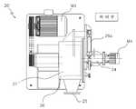
도 3은 원심분리방식의 정제장치의 일실시예인 포집용 원심분리기(20)를 나타낸 것으로, 상기 포집용 원심분리기(20)는 수평으로 설치된 원통형태의 하우징(21) 내측으로 양단이 베어링으로 지지되어 회전가능하도록 수평으로 설치된 원통형태의 바울(22)과, 상기 바울(22) 내측으로 양단이 베어링으로 지지되어 회전가 능하도록 수평으로 설치된 스크류 축(23)에는 각각 바울용 모터(M1)와 스크류 축용 모터(M2)가 설치되어 각각 구동과 회전이 각각 제어되도록 이루어진다.3 shows a
좀더 상세하게 설명하면, 상기 포집용 원심분리기(20)는 크게 하우징(21)과, 상기 하우징(21) 내측으로 바울용 모터(M1)의 동력을 전달받아 회전하는 수평으로 설치된 원통형태의 바울(22)과, 상기 바울(22) 내측으로 스크류 축용 모터(M2)의 동력을 전달받아 회전하는 스크류 형태의 날개(23-1)가 형성된 수평으로 설치된 원통형태의 스크류 축(23)과, 상기 스크류 축(23)의 내측으로 슬러리를 공급하는 공급관과, 포집되는 실리콘 파우더를 배출하는 실리콘 파우더 배출구(24)와, 폐슬러리로부터 실리콘 파우더가 분리된 저농도 폐슬러리를 배출하는 슬러리 배출구(25)와, 상기 바울(22)과 스크류 축(23)의 회전과 폐슬러리 유량(Q)을 제어하는 제어부로 구성된다.In more detail, the
상기 바울(22)과 스크류 축(23)에는 각각 제어부로부터 용이하게 구동과 회전을 각각 조절할 수 있도록 각각의 바울용 모터(M1)와 스크류 축용 모터(M2)가 설치되고, 각각 동력전달장치로 연설되어 각각의 바울용 모터(M1)와 스크류 축용 모터(M2)의 동력으로 바울(22)과 스크류 축(23)에는 구동하게 된다.Each of the
상기 포집용 원심분리기(20)는 본 출원인이 출원하여 등록된 국내특허등록 제896069호에 보다 상세하게 설명되어 있으며, 상세한 내용은 국내특허등록 제896069호의 공보를 참조하기로 한다.The
도 4와 도 5는 상기 원심분리방식의 정제장치의 다른 실시예인 정제기용 원 심분리기(20')를 나타낸 것으로, 상기 정제기용 원심분리기(20')는 크게 베이스와, 상기 베이스 위에 수평으로 설치된 원통형태의 하우징(26)과 상기 하우징(26) 내측으로 회전가능하게 수평으로 설치된 원통형태의 바울(27)과, 상기 바울(27)을 회전시키기 위하여 동력전달장치로 연설되는 주 모터(M3)와, 상기 바울(27)에서 정제된 실리콘 파우더가 배출되는 실리콘 파우더 배출구(24)과, 상기 바울(27) 내측면에 정제되어 포집되어 있는 실리콘 파우더를 배출시키는 주걱날(28)과, 상기 바울(27) 내측으로 고농도 폐슬러리를 공급하는 공급관과, 상기 각각의 구성요소들을 제어하는 제어부(100)로 구성된다.4 and 5 illustrate a centrifuge 20 'for a refiner, which is another embodiment of the centrifugal purification apparatus, wherein the centrifuge 20' for a refiner is largely installed on a base and horizontally on the base.
상기 하우징(26)은 원통형태로 형성되어 베이스의 상부에 수평으로 설치된것으로, 하측부분에는 저순도 폐슬러리를 배출하는 슬러리 배출구(25)가 형성되어 상기 바울(27)에서 고농도 폐슬러리로부터 실리콘 파우더(S)가 분리된 나머지 저농도 폐슬러리가 배출된다.The
상기 하우징(26)의 일측에는 후설되는 바울(27)을 회전시키는 회전축이 설치되는 회전축 하우징이 설치된다.One side of the
상기 바울(27)은 원통 형태로 형성되어 하우징(26)의 내측에 수평으로 회전하도록 설치되어 주 모터(M3)의 동력을 전달받아 회전한다.The Paul 27 is formed in a cylindrical shape is installed to rotate horizontally inside the
상기 실리콘 파우더 배출구(24)는 하우징(26)을 관통하여 바울(27)에 형성된 구멍을 통해 바울(27)의 내측으로 설치된다.The
상기 실리콘 파우더 배출구(24)는 바울(27)의 내측에 설치되어 있는 주걱날(28)에 의하여 공급되는 실리콘 파우더(S)를 배출하는 것으로, 모터(M4)와 상기 모터(M4)와 연결되어 회전하는 스크류가 설치되어 있다.The
상기 정제기용 원심분리기(20')는 본 출원인이 출원하여 등록된 국내특허등록 제896070호에 보다 상세하게 설명되어 있으며, 상세한 내용은 국내특허등록 제896070호의 공보를 참조하기로 한다.The centrifuge 20 'for the purifier is described in more detail in Korean Patent Registration No. 896070, filed by the applicant, and for details, refer to the publication of Korean Patent Registration No. 896070.
상기 포집용 원심분리기(20) 또는 정제기용 원심분리기(20')에서 고농도의 폐슬러리에서 제거되는 실리콘 파우더는 별도로 포집되어 직접 또는 별도의 정제과정 후 건조와 용융과정으로 태양전지 등의 원료로 사용되는 청크로 제작되어 재활용된다.The silicon powder removed from the waste slurry of high concentration in the
상기 필터방식의 정제장치(30)는 통상적인 필터를 사용하여 불순물을 걸러 정제하는 장치이며, 사용되는 필터는 보통 맴브레인 필터를 사용한다.The filter
상기 필터방식의 정제장치(30)는 원심분리방식의 정제장치(20)를 통과한 저순도의 폐슬러리를 필터를 통과시킴으로써 저순도의 폐슬러리 내에 포함되어 있는 실리콘 파우더와 같은 불순물(이물질)을 제거(포집)하여 정제한다.The filter
상기 필터방식의 정제장치(30)는 1단 또는 2단 이상의 다단의 필터로 구성될 수 있다.The filter
또는, 상기 필터방식의 정제장치를 다수개로 직렬배치하여 저순도 폐슬러리가 다수개의 필터방식의 정제장치를 통과하도록 할 수 있다.Alternatively, the filter type purification apparatus may be arranged in series to allow the low purity waste slurry to pass through the plurality of filter purification apparatuses.
다단의 필터로 구성되거나 또는 다수개로 직렬배치된 필터방식의 정제장치를 통과할수록 더욱 깨끗한 물로 정제될 수 있다, 그러나 그 효율성과 경제성을 고려 할 때 필터는 1단 내지 4단으로 이루어지는 것이 바람직하고, 필터방식의 정제장치도 1 내지 4개 직렬배치하는 바람직하다.The filter is composed of a multi-stage filter or a plurality of filters arranged in series can be purified more clean water, but considering the efficiency and economy, the filter is preferably composed of 1 to 4 stages, It is preferable to also arrange 1 to 4 filter apparatuses in series.
상기 필터방식의 정제장치(30)를 통과하여 정제된 물은 바로 공업용수로 사용되거나 중수로 사용되게 된다.The purified water passing through the filter
또는, 상기 필터방식의 정제장치(30)를 통과하여 정제된 물은 정수처리장으로 이동되어 상수로 사용할 수도 있다.Alternatively, the purified water passing through the filter
상기 필터방식의 정제장치(30)에서 포집되는 실리콘 파우더는 원심분리방식의 정제장치(20)에서 포집된 실리콘 파우더와 혼합되어 청크로 제작되거나, 또는 원심분리방식의 정제장치(20)에서 포집된 실리콘 파우더와 구별되어 청크로 제작되어 재활용된다.The silicon powder collected in the
도 1은 본 발명의 단계를 나타낸 단계도.1 is a step diagram showing the steps of the present invention.
도 2는 본 발명의 실시예를 나타낸 개략도.2 is a schematic view showing an embodiment of the present invention.
도 3은 본 발명에 사용되는 원심분리방식의 정제장치의 일실시예를 나타낸 포집용 원심분리기의 평단면도.Figure 3 is a cross-sectional plan view of a collection centrifuge showing an embodiment of a centrifugal purification apparatus used in the present invention.
도 4는 본 발명에 사용되는 원심분리방식의 정제장치의 일실시예를 나타낸 정제용 원심분리기의 평면도.Figure 4 is a plan view of a centrifuge for purification showing one embodiment of a centrifugal purification apparatus used in the present invention.
도 5는 본 발명에 사용되는 원심분리방식의 정제장치의 일실시예를 나타낸 정제용 원심분리기의 정단면도.Figure 5 is a front sectional view of a centrifuge for purification showing one embodiment of a centrifugal purification apparatus used in the present invention.
[도면의 주요부분에 대한 부호의 설명][Explanation of symbols on the main parts of the drawings]
S10 : 원심분리방식의 정제단계S10: centrifugation purification step
S20 : 필터방식의 정제단계S20: Filtering Step
10 : 고농도의 폐슬러리10: high concentration waste slurry
20, 20' : 원심분리방식의 정제장치20, 20 ': centrifugal purification system
21, 26 : 하우징22, 27 : 바울21, 26:
23 : 스크류축23-1 : 날개23: screw shaft 23-1: wing
24 : 실리콘 파우더 배출구24: silicon powder outlet
25 : 슬러리 배출구25: slurry outlet
28 : 주걱28a : 주걱작동 실린더28:
M1, M2, M3, M4 : 모터M1, M2, M3, M4: Motor
Claims (6)
Translated fromKoreanPriority Applications (1)
| Application Number | Priority Date | Filing Date | Title |
|---|---|---|---|
| KR20090096657AKR100958566B1 (en) | 2009-10-12 | 2009-10-12 | Water treatment system of slurry production back lapping process |
Applications Claiming Priority (1)
| Application Number | Priority Date | Filing Date | Title |
|---|---|---|---|
| KR20090096657AKR100958566B1 (en) | 2009-10-12 | 2009-10-12 | Water treatment system of slurry production back lapping process |
Publications (1)
| Publication Number | Publication Date |
|---|---|
| KR100958566B1true KR100958566B1 (en) | 2010-05-17 |
Family
ID=42281837
Family Applications (1)
| Application Number | Title | Priority Date | Filing Date |
|---|---|---|---|
| KR20090096657AExpired - Fee RelatedKR100958566B1 (en) | 2009-10-12 | 2009-10-12 | Water treatment system of slurry production back lapping process |
Country Status (1)
| Country | Link |
|---|---|
| KR (1) | KR100958566B1 (en) |
Cited By (10)
| Publication number | Priority date | Publication date | Assignee | Title |
|---|---|---|---|---|
| KR101391709B1 (en) | 2012-07-10 | 2014-05-07 | 주식회사 시노펙스워터 | a method of treating emulsified oil wastewater for industrial water reuse |
| US11923995B2 (en) | 2009-01-28 | 2024-03-05 | Headwater Research Llc | Device-assisted services for protecting network capacity |
| US11966464B2 (en) | 2009-01-28 | 2024-04-23 | Headwater Research Llc | Security techniques for device assisted services |
| US11985155B2 (en) | 2009-01-28 | 2024-05-14 | Headwater Research Llc | Communications device with secure data path processing agents |
| US12101434B2 (en) | 2009-01-28 | 2024-09-24 | Headwater Research Llc | Device assisted CDR creation, aggregation, mediation and billing |
| US12137004B2 (en) | 2009-01-28 | 2024-11-05 | Headwater Research Llc | Device group partitions and settlement platform |
| US12309024B2 (en) | 2009-01-28 | 2025-05-20 | Headwater Research Llc | Quality of service for device assisted services |
| US12389217B2 (en) | 2009-01-28 | 2025-08-12 | Headwater Research Llc | Device assisted services install |
| US12389218B2 (en) | 2009-01-28 | 2025-08-12 | Headwater Research Llc | Service selection set publishing to device agent with on-device service selection |
| US12401984B2 (en) | 2009-01-28 | 2025-08-26 | Headwater Research Llc | Enhanced roaming services and converged carrier networks with device assisted services and a proxy |
Citations (2)
| Publication number | Priority date | Publication date | Assignee | Title |
|---|---|---|---|---|
| JP2005021805A (en)* | 2003-07-02 | 2005-01-27 | Sumitomo Mitsubishi Silicon Corp | Method and system for treating waste water |
| KR100896071B1 (en)* | 2008-03-05 | 2009-05-07 | (주)실파인 | Recycling method of silicon powder from slurry generated from back lapping process |
- 2009
- 2009-10-12KRKR20090096657Apatent/KR100958566B1/ennot_activeExpired - Fee Related
Patent Citations (2)
| Publication number | Priority date | Publication date | Assignee | Title |
|---|---|---|---|---|
| JP2005021805A (en)* | 2003-07-02 | 2005-01-27 | Sumitomo Mitsubishi Silicon Corp | Method and system for treating waste water |
| KR100896071B1 (en)* | 2008-03-05 | 2009-05-07 | (주)실파인 | Recycling method of silicon powder from slurry generated from back lapping process |
Cited By (11)
| Publication number | Priority date | Publication date | Assignee | Title |
|---|---|---|---|---|
| US11923995B2 (en) | 2009-01-28 | 2024-03-05 | Headwater Research Llc | Device-assisted services for protecting network capacity |
| US11966464B2 (en) | 2009-01-28 | 2024-04-23 | Headwater Research Llc | Security techniques for device assisted services |
| US11985155B2 (en) | 2009-01-28 | 2024-05-14 | Headwater Research Llc | Communications device with secure data path processing agents |
| US12101434B2 (en) | 2009-01-28 | 2024-09-24 | Headwater Research Llc | Device assisted CDR creation, aggregation, mediation and billing |
| US12137004B2 (en) | 2009-01-28 | 2024-11-05 | Headwater Research Llc | Device group partitions and settlement platform |
| US12166596B2 (en) | 2009-01-28 | 2024-12-10 | Disney Enterprises, Inc. | Device-assisted services for protecting network capacity |
| US12309024B2 (en) | 2009-01-28 | 2025-05-20 | Headwater Research Llc | Quality of service for device assisted services |
| US12389217B2 (en) | 2009-01-28 | 2025-08-12 | Headwater Research Llc | Device assisted services install |
| US12389218B2 (en) | 2009-01-28 | 2025-08-12 | Headwater Research Llc | Service selection set publishing to device agent with on-device service selection |
| US12401984B2 (en) | 2009-01-28 | 2025-08-26 | Headwater Research Llc | Enhanced roaming services and converged carrier networks with device assisted services and a proxy |
| KR101391709B1 (en) | 2012-07-10 | 2014-05-07 | 주식회사 시노펙스워터 | a method of treating emulsified oil wastewater for industrial water reuse |
Similar Documents
| Publication | Publication Date | Title |
|---|---|---|
| KR100958566B1 (en) | Water treatment system of slurry production back lapping process | |
| EP2583949A1 (en) | Purification processing device of oil-containing sewage | |
| CN101426723B (en) | Method and apparatus for treating silicon particle | |
| CN102206013B (en) | Device for recycling silicon powder and waste water from waste water from silicon cutting and method thereof | |
| EP2094441B1 (en) | Process and apparatus for treating exhausted abrasive slurries from the lapping process for the recovery of their reusable abrasive component | |
| JP3683870B2 (en) | Dust water washing system and dust water washing method | |
| JP3816200B2 (en) | Method and apparatus for processing liquid containing fine particles | |
| WO2005028379A1 (en) | Method and apparatus for treating drain water from step of washing fly ash with water | |
| KR20120011990A (en) | Brush Type Fine Dust Collector | |
| JP5011409B2 (en) | Environmentally friendly solid-liquid separation system | |
| KR20030005575A (en) | Regenerating process and regenerating system to regenerate waste slurry from semiconductor wafer manufacturing process | |
| CN102897931A (en) | Sewage purification and circulation system in semiconductor industry | |
| CN202030600U (en) | Silica powder and waste water recycling device for silicon cutting waste water | |
| KR100896071B1 (en) | Recycling method of silicon powder from slurry generated from back lapping process | |
| EP4166501A1 (en) | Method for recovering gypsum from waste gypsum boards | |
| CN103496831A (en) | Recycling method of silicon wafer cutting edge material waste water treatment sludge | |
| JP2942884B2 (en) | Method and apparatus for removing sand from night soil and septic tank sludge | |
| JPH0643292A (en) | Radioactive waste liquid treatment device | |
| JP2004243185A (en) | Solid-liquid separation treatment method and apparatus therefor | |
| EP3230422A1 (en) | Method and system for washing of crude tall oil soap | |
| CN111203030B (en) | High-efficiency recyclable solid-liquid separation method for industrial wastewater | |
| JPH1073079A (en) | Water and air cleaning method for water sealed type vacuum pump | |
| JPH11300115A (en) | Slurry separation method and apparatus | |
| CN211770794U (en) | Process water treatment system of concentrating mill | |
| CN104649446A (en) | Liquid-solid separation method and device for MTO (methanol to olefins) quenching water and washing water |
Legal Events
| Date | Code | Title | Description |
|---|---|---|---|
| A201 | Request for examination | ||
| PA0109 | Patent application | St.27 status event code:A-0-1-A10-A12-nap-PA0109 | |
| PA0201 | Request for examination | St.27 status event code:A-1-2-D10-D11-exm-PA0201 | |
| A302 | Request for accelerated examination | ||
| PA0302 | Request for accelerated examination | St.27 status event code:A-1-2-D10-D17-exm-PA0302 St.27 status event code:A-1-2-D10-D16-exm-PA0302 | |
| D13-X000 | Search requested | St.27 status event code:A-1-2-D10-D13-srh-X000 | |
| D14-X000 | Search report completed | St.27 status event code:A-1-2-D10-D14-srh-X000 | |
| E902 | Notification of reason for refusal | ||
| PE0902 | Notice of grounds for rejection | St.27 status event code:A-1-2-D10-D21-exm-PE0902 | |
| E13-X000 | Pre-grant limitation requested | St.27 status event code:A-2-3-E10-E13-lim-X000 | |
| P11-X000 | Amendment of application requested | St.27 status event code:A-2-2-P10-P11-nap-X000 | |
| P13-X000 | Application amended | St.27 status event code:A-2-2-P10-P13-nap-X000 | |
| E701 | Decision to grant or registration of patent right | ||
| PE0701 | Decision of registration | St.27 status event code:A-1-2-D10-D22-exm-PE0701 | |
| GRNT | Written decision to grant | ||
| PR0701 | Registration of establishment | St.27 status event code:A-2-4-F10-F11-exm-PR0701 | |
| PR1002 | Payment of registration fee | St.27 status event code:A-2-2-U10-U11-oth-PR1002 Fee payment year number:1 | |
| PG1601 | Publication of registration | St.27 status event code:A-4-4-Q10-Q13-nap-PG1601 | |
| LAPS | Lapse due to unpaid annual fee | ||
| PC1903 | Unpaid annual fee | St.27 status event code:A-4-4-U10-U13-oth-PC1903 Not in force date:20130512 Payment event data comment text:Termination Category : DEFAULT_OF_REGISTRATION_FEE | |
| PC1903 | Unpaid annual fee | St.27 status event code:N-4-6-H10-H13-oth-PC1903 Ip right cessation event data comment text:Termination Category : DEFAULT_OF_REGISTRATION_FEE Not in force date:20130512 | |
| P22-X000 | Classification modified | St.27 status event code:A-4-4-P10-P22-nap-X000 | |
| P22-X000 | Classification modified | St.27 status event code:A-4-4-P10-P22-nap-X000 | |
| P22-X000 | Classification modified | St.27 status event code:A-4-4-P10-P22-nap-X000 | |
| P22-X000 | Classification modified | St.27 status event code:A-4-4-P10-P22-nap-X000 |