KR100957700B1 - RDF Reader Demodulation Apparatus and Method for Subcarrier Tag Signals - Google Patents
RDF Reader Demodulation Apparatus and Method for Subcarrier Tag SignalsDownload PDFInfo
- Publication number
- KR100957700B1 KR100957700B1KR1020080079337AKR20080079337AKR100957700B1KR 100957700 B1KR100957700 B1KR 100957700B1KR 1020080079337 AKR1020080079337 AKR 1020080079337AKR 20080079337 AKR20080079337 AKR 20080079337AKR 100957700 B1KR100957700 B1KR 100957700B1
- Authority
- KR
- South Korea
- Prior art keywords
- signal
- edge
- tag signal
- tag
- value
- Prior art date
- Legal status (The legal status is an assumption and is not a legal conclusion. Google has not performed a legal analysis and makes no representation as to the accuracy of the status listed.)
- Expired - Fee Related
Links
Images


Classifications
- H—ELECTRICITY
- H04—ELECTRIC COMMUNICATION TECHNIQUE
- H04L—TRANSMISSION OF DIGITAL INFORMATION, e.g. TELEGRAPHIC COMMUNICATION
- H04L27/00—Modulated-carrier systems
- H04L27/02—Amplitude-modulated carrier systems, e.g. using on-off keying; Single sideband or vestigial sideband modulation
- H04L27/06—Demodulator circuits; Receiver circuits
- G—PHYSICS
- G06—COMPUTING OR CALCULATING; COUNTING
- G06K—GRAPHICAL DATA READING; PRESENTATION OF DATA; RECORD CARRIERS; HANDLING RECORD CARRIERS
- G06K7/00—Methods or arrangements for sensing record carriers, e.g. for reading patterns
- G06K7/10—Methods or arrangements for sensing record carriers, e.g. for reading patterns by electromagnetic radiation, e.g. optical sensing; by corpuscular radiation
- G06K7/10009—Methods or arrangements for sensing record carriers, e.g. for reading patterns by electromagnetic radiation, e.g. optical sensing; by corpuscular radiation sensing by radiation using wavelengths larger than 0.1 mm, e.g. radio-waves or microwaves
- G06K7/10297—Methods or arrangements for sensing record carriers, e.g. for reading patterns by electromagnetic radiation, e.g. optical sensing; by corpuscular radiation sensing by radiation using wavelengths larger than 0.1 mm, e.g. radio-waves or microwaves arrangements for handling protocols designed for non-contact record carriers such as RFIDs NFCs, e.g. ISO/IEC 14443 and 18092
- H—ELECTRICITY
- H04—ELECTRIC COMMUNICATION TECHNIQUE
- H04B—TRANSMISSION
- H04B5/00—Near-field transmission systems, e.g. inductive or capacitive transmission systems
- H04B5/40—Near-field transmission systems, e.g. inductive or capacitive transmission systems characterised by components specially adapted for near-field transmission
- H04B5/48—Transceivers
- H—ELECTRICITY
- H04—ELECTRIC COMMUNICATION TECHNIQUE
- H04L—TRANSMISSION OF DIGITAL INFORMATION, e.g. TELEGRAPHIC COMMUNICATION
- H04L27/00—Modulated-carrier systems
- H04L27/18—Phase-modulated carrier systems, i.e. using phase-shift keying
- H04L27/22—Demodulator circuits; Receiver circuits
- H—ELECTRICITY
- H04—ELECTRIC COMMUNICATION TECHNIQUE
- H04Q—SELECTING
- H04Q2213/00—Indexing scheme relating to selecting arrangements in general and for multiplex systems
- H04Q2213/13095—PIN / Access code, authentication
Landscapes
- Engineering & Computer Science (AREA)
- Computer Networks & Wireless Communication (AREA)
- Signal Processing (AREA)
- Health & Medical Sciences (AREA)
- Toxicology (AREA)
- Physics & Mathematics (AREA)
- Electromagnetism (AREA)
- General Health & Medical Sciences (AREA)
- Artificial Intelligence (AREA)
- Computer Vision & Pattern Recognition (AREA)
- General Physics & Mathematics (AREA)
- Theoretical Computer Science (AREA)
- Computer Security & Cryptography (AREA)
- Near-Field Transmission Systems (AREA)
Abstract
Translated fromKoreanDescription
Translated fromKorean본 발명의 실시예들은 RFID 리더의 복조 장치 및 방법에 관련한 것이다.Embodiments of the present invention relate to a demodulation device and method of an RFID reader.
본 발명은 지식경제부 및 정보통신연구진흥원의The invention of the Ministry of Knowledge Economy and ICTITIT원천기술개발사업의 일환으로 수행한 연구로부터 도출된 것이다[과제관리번호: 2008-F-052-01, 과제명: 개별물품 단위 응용을 위한 차세대It was derived from research conducted as part of the original technology development project. [Task Management No .: 2008-F-052-01, Title: Next Generation for Individual Unit Unit Application]RFIDRFID 기술 개발]. Technology development].
일반적으로, 무선주파수인식(Radio Frequency Identification, RFID)은 무선 주파수를 사용하여 고유한 식별 정보를 가지고 있는 태그(tag)로부터 비접촉식으로 정보를 독출하거나 기록함으로써 태그가 부착된 물건, 동물 및 사람 등을 인식, 추적 및 관리할 수 있도록 하는 기술이다. RFID 시스템은 고유한 식별 정보를 지니며 물건이나 동물 등에 부착되는 다수의 태그(electronic tag 또는 transponder)와 태그의 정보를 읽거나 쓰기 위한 RFID 리더(Reader 또는 Interrogator)로 구성된다.In general, Radio Frequency Identification (RFID) uses radio frequency to read or record information from a tag having unique identification information in a non-contact manner to identify tagged objects, animals, and people. A technology that enables recognition, tracking, and management. The RFID system is composed of a plurality of tags (electronic tags or transponders) attached to an object or animal with unique identification information, and an RFID reader or interrogator for reading or writing the information of the tags.
이러한RFID 시스템은 리더와 태그 사이의 상호 통신 방식에 따라 상호 유도 방식과 전자기파 방식으로 구분되고, 태그가 자체 전력으로 동작하는지 여부에 따라 능동형과 수동형으로 구분되며, 사용하는 주파수에 따라 장파형, 중파형, 단파형, 초단파형 및 극초단파형 등으로 구분된다.These RFID systems are classified into mutual induction and electromagnetic waves according to the intercommunication method between the reader and the tag, and are classified into active and passive types according to whether the tag operates with its own power. It is divided into shape, short wave, ultra short wave and ultra short wave.
한편, 수동형 RFID 태그와 통신하는 RFID 리더는, 태그 신호를 수신하는 동안 송신 에너지(TX CW)를 수동형 RFID 태그에 계속 공급해야 하기 때문에, 송수신 분리도가 충분히 확보되지 않으면 많은 양의 송신 에너지(TX CW) 성분이 RFID 리더의 수신단(RX)으로 누설된다.On the other hand, the RFID reader communicating with the passive RFID tag must continuously supply the transmit energy (TX CW) to the passive RFID tag while receiving the tag signal. ) Component leaks to the receiving end RX of the RFID reader.
RFID 리더의 수신단으로 누설된 송신 에너지(TX CW) 성분은 리더의 베이스밴드단에서 오프셋 왜곡 잡음(DC-offset noise)을 발생시킬 수 있다. 따라서, RFID 리더는 상기 발생된 오프셋 왜곡 잡음으로 인해 상기 태그 신호의 복조 시 원래의 신호를 제대로 복원하지 못하거나 성능이 저하되는 등의 문제점이 있다.The transmission energy (TX CW) component leaked to the receiving end of the RFID reader may generate offset distortion noise (DC-offset noise) at the baseband end of the reader. Accordingly, the RFID reader has a problem such that due to the generated offset distortion noise, the original signal may not be properly restored or performance may be degraded when demodulating the tag signal.
본 발명은 상기와 같은 종래 기술을 개선하기 위해 안출된 것으로서, 본 발명의 목적은 서브 캐리어 방식의 태그 신호에 대해, 서브 캐리어가 제거된 에지 신호(edge signal)를 이용하여 복조를 수행함으로써, 상기 태그 신호에 오프셋 왜곡 잡음이 발생하더라도 상기 태그 신호의 복조에 대한 신뢰성을 높일 수 있는 장치 및 방법을 제공하는 것이다.SUMMARY OF THE INVENTION The present invention has been made to improve the prior art as described above, and an object of the present invention is to perform demodulation using an edge signal from which a subcarrier is removed for a tag signal of a subcarrier type. The present invention provides an apparatus and method for improving reliability of demodulation of a tag signal even when offset distortion noise occurs in a tag signal.
본 발명의 다른 목적은 태그 신호의 변조 방식에 상관 없이, 수신되는 태그 신호에 대한 에지 신호 및 에지 성분(정보)를 추출하여 ASK(Amplitude Shift Keying) 또는 BPSK(Binary Phase Shift Keying) 방식으로 복조할 수 있는 장치 및 방법을 제공하는 것이다.Another object of the present invention is to extract an edge signal and an edge component (information) for a received tag signal and demodulate it using ASK (Amplitude Shift Keying) or BPSK (Binary Phase Shift Keying) regardless of a modulation method of a tag signal. It is to provide an apparatus and method that can be.
본 발명의 또 다른 목적은 복조 및 디코딩에 신호의 에지 성분(정보)을 이용하기 때문에, RFID 태그와 RFID 리더 간의 거리에 따른 위상이 변화하더라도 간단한 구조로 위상 다이버시티를 구현할 수 있도록 하는 장치 및 방법을 제공하는 것이다.Another object of the present invention is to use an edge component (information) of a signal for demodulation and decoding, so that a device and method for implementing phase diversity with a simple structure even when a phase changes according to a distance between an RFID tag and an RFID reader can be realized. To provide.
본 발명의 목적은 이상에서 언급한 목적들로 제한되지 않으며, 언급되지 않은 또 다른 목적들은 아래의 기재로부터 당업자에게 명확하게 이해될 수 있을 것이다.The object of the present invention is not limited to the above-mentioned objects, and other objects not mentioned will be clearly understood by those skilled in the art from the following description.
상기의 목적을 이루고 종래기술의 문제점을 해결하기 위하여, 본 발명의 실 시예에 따른 서브 캐리어 방식의 태그 신호에 대한 RFID 리더의 복조 장치는, 서브 캐리어 방식의 태그 신호를 수신하여 상기 태그 신호에 대한 에지 신호를 생성하는 에지 신호 생성부; 상기 생성된 에지 신호로부터 에지 정보를 추출하는 에지 정보 추출부; 및 상기 추출된 에지 정보를 이용하여 상기 태그 신호를 디코딩하는 디코딩부를 포함한다.In order to achieve the above object and solve the problems of the prior art, the demodulation device of the RFID reader for the tag signal of the sub-carrier type according to the embodiment of the present invention, receiving a tag signal of the sub-carrier type to the tag signal An edge signal generator for generating an edge signal; An edge information extraction unit for extracting edge information from the generated edge signal; And a decoding unit decoding the tag signal using the extracted edge information.
상기 에지 신호 생성부는, 상기 태그 신호로부터 위상 반전이 일어나는 위치를 검출하고, 상기 검출된 위치에 상기 에지 신호를 생성할 수 있다.The edge signal generation unit may detect a position at which phase inversion occurs from the tag signal and generate the edge signal at the detected position.
상기 에지 정보 추출부는, 상기 생성된 에지 신호의 현재 샘플값과 적어도 하나의 이전 샘플값을 비교하여, 상기 에지 신호의 첨두점을 검출하고, 상기 검출된 첨두점을 이용하여 상기 에지 정보를 추출할 수 있다.The edge information extracting unit may compare a current sample value of the generated edge signal with at least one previous sample value, detect a peak point of the edge signal, and extract the edge information by using the detected peak point. Can be.
상기 에지 정보 추출부는, 상기 적어도 하나의 이전 샘플값 중, 상기 현재 샘플값과의 차가 최고인 값과 최저인 값을 각각 최고값과 최저값으로서 산출하고, 상기 산출된 최고값과 최저값을 이용하여, 상기 생성된 에지 신호의 기울기가 양에서 음으로 바뀌는 부분을 상기 첨두점으로서 검출할 수 있다.The edge information extracting unit may calculate, as the highest value and the lowest value, the highest value and the lowest value of the difference between the current sample value and the lowest value among the at least one previous sample value, respectively. The portion where the slope of the generated edge signal changes from positive to negative can be detected as the peak.
상기 에지 정보 추출부는, 상기 추출된 에지 정보를 이용하여 에지 클럭을 생성하고, 상기 디코딩부는, 상기 생성된 에지 클럭을 이용하여 비트 데이터를 결정하고, 상기 결정된 비트 데이터를 이용하여 상기 태그 신호의 프리앰블을 검출하며, 상기 검출된 프리앰블을 이용하여 상기 태그 신호를 디코딩할 수 있다.The edge information extracting unit generates an edge clock using the extracted edge information, and the decoding unit determines bit data using the generated edge clock, and uses the determined bit data to preamble the tag signal. And detect the tag signal by using the detected preamble.
본 발명의 실시예에 따른 서브 캐리어 방식의 태그 신호에 대한 RFID 리더의 복조 방법은, 서브 캐리어 방식의 태그 신호를 수신하여 상기 태그 신호에 대한 에지 신호를 생성하는 단계; 상기 생성된 에지 신호로부터 에지 정보를 추출하는 단계; 및 상기 추출된 에지 정보를 이용하여 상기 태그 신호를 디코딩하는 단계를 포함한다.According to an embodiment of the present invention, a method of demodulating an RFID reader for a tag signal of a subcarrier method includes: receiving an tag signal of a subcarrier method and generating an edge signal for the tag signal; Extracting edge information from the generated edge signal; And decoding the tag signal using the extracted edge information.
상기 서브 캐리어 방식의 태그 신호를 수신하여 상기 태그 신호에 대한 에지 신호를 생성하는 단계는, 상기 태그 신호로부터 위상 반전이 일어나는 위치를 검출하는 단계; 및 상기 검출된 위치에 상기 에지 신호를 생성하는 단계를 포함할 수 있다.Receiving the tag signal of the sub-carrier scheme and generating an edge signal for the tag signal, detecting the position where the phase inversion occurs from the tag signal; And generating the edge signal at the detected position.
상기 생성된 에지 신호로부터 에지 정보를 추출하는 단계는, 상기 생성된 에지 신호의 현재 샘플값과 적어도 하나의 이전 샘플값을 비교하여, 상기 에지 신호의 첨두점을 검출하는 단계; 및 상기 검출된 첨두점을 이용하여 상기 에지 정보를 추출하는 단계를 포함할 수 있다.Extracting edge information from the generated edge signal may include comparing a current sample value of the generated edge signal with at least one previous sample value to detect a peak point of the edge signal; And extracting the edge information by using the detected peak.
상기 생성된 에지 신호의 현재 샘플값과 적어도 하나의 이전 샘플값을 비교하여, 상기 에지 신호의 첨두점을 검출하는 단계는, 상기 적어도 하나의 이전 샘플값 중, 상기 현재 샘플값과의 차가 최고인 값과 최저인 값을 각각 최고값과 최저값으로서 산출하는 단계; 및 상기 산출된 최고값과 최저값을 이용하여, 상기 생성된 에지 신호의 기울기가 양에서 음으로 바뀌는 부분을 상기 첨두점으로서 검출하는 단계를 포함할 수 있다.The detecting of the peak point of the edge signal by comparing the current sample value of the generated edge signal with at least one previous sample value comprises: a value having a maximum difference with the current sample value among the at least one previous sample value. Calculating the lowest and lowest values as the highest and lowest values, respectively; And detecting, as the peak, a portion where the slope of the generated edge signal is changed from positive to negative using the calculated highest and lowest values.
상기 생성된 에지 신호로부터 에지 정보를 추출하는 단계는, 상기 추출된 에지 정보를 이용하여 에지 클럭을 생성하는 단계를 포함하고, 상기 추출된 에지 정보를 이용하여 상기 태그 신호를 디코딩하는 단계는, 상기 생성된 에지 클럭을 이용하여 비트 데이터를 결정하는 단계; 상기 결정된 비트 데이터를 이용하여 상기 태그 신호의 프리앰블을 검출하는 단계; 및 상기 검출된 프리앰블을 이용하여 상기 태그 신호를 디코딩하는 단계를 포함할 수 있다.Extracting edge information from the generated edge signal includes generating an edge clock using the extracted edge information, and decoding the tag signal using the extracted edge information comprises: Determining bit data using the generated edge clock; Detecting a preamble of the tag signal using the determined bit data; And decoding the tag signal using the detected preamble.
기타 실시예들의 구체적인 사항들은 상세한 설명 및 첨부 도면들에 포함되어 있다.Specific details of other embodiments are included in the detailed description and the accompanying drawings.
본 발명의 이점 및 특징, 그리고 그것들을 달성하는 방법은 첨부되는 도면과 함께 상세하게 후술되어 있는 실시예들을 참조하면 명확해질 것이다. 그러나, 본 발명은 이하에서 개시되는 실시예들에 한정되는 것이 아니라 서로 다른 다양한 형태로 구현될 것이며, 단지 본 실시예들은 본 발명의 개시가 완전하도록 하며, 본 발명이 속하는 기술분야에서 통상의 지식을 가진 자에게 발명의 범주를 완전하게 알려주기 위해 제공되는 것이며, 본 발명은 청구항의 범주에 의해 정의될 뿐이다. 명세서 전체에 걸쳐 동일 참조 부호는 동일 구성요소를 지칭한다.Advantages and features of the present invention and methods for achieving them will be apparent with reference to the embodiments described below in detail with the accompanying drawings. However, the present invention is not limited to the embodiments disclosed below, but will be implemented in various different forms, and only the embodiments make the disclosure of the present invention complete, and those skilled in the art to which the present invention pertains. It is provided to fully inform the person having the scope of the invention, which is defined only by the scope of the claims. Like reference numerals refer to like elements throughout.
본 발명의 실시예들에 따르면, 서브 캐리어 방식의 태그 신호에 대해, 서브 캐리어가 제거된 에지 신호를 이용하여 복조를 수행함으로써, 상기 태그 신호에 오프셋 왜곡 잡음이 발생하더라도 상기 태그 신호의 복조에 대한 신뢰성을 높일 수 있다.According to embodiments of the present invention, demodulation is performed on an edge signal from which a subcarrier has been removed using a subcarrier-type tag signal, so that even if offset distortion noise occurs in the tag signal, demodulation of the tag signal is performed. It can increase the reliability.
본 발명의 실시예들에 따르면, 태그 신호의 변조 방식에 상관 없이, 수신되는 태그 신호에 대한 에지 신호 및 에지 성분(정보)를 추출하여 ASK(Amplitude Shift Keying) 또는 BPSK(Binary Phase Shift Keying) 방식으로 복조할 수 있다.According to the embodiments of the present invention, regardless of the modulation method of the tag signal, an edge signal and an edge component (information) for the received tag signal are extracted to obtain an Amplitude Shift Keying (ASK) or Binary Phase Shift Keying (BPSK) scheme. Can be demodulated by
본 발명의 실시예들에 따르면, 복조 및 디코딩에 신호의 에지 성분(정보)을 이용하기 때문에, RFID 태그와 RFID 리더 간의 거리에 따른 위상이 변화하더라도 간단한 구조로 위상 다이버시티를 구현할 수 있다.According to embodiments of the present invention, since the edge component (information) of the signal is used for demodulation and decoding, even if the phase changes according to the distance between the RFID tag and the RFID reader, phase diversity can be implemented with a simple structure.
이하에서는 첨부된 도면을 참조하여 본 발명의 실시예를 상세히 설명한다.Hereinafter, embodiments of the present invention will be described in detail with reference to the accompanying drawings.
도 1은 본 발명의 실시예에 따른 서브 캐리어 방식의 태그 신호에 대한 RFID 리더의 복조 장치를 설명하기 위해 도시한 블록도이다.1 is a block diagram illustrating a demodulation device of an RFID reader for a tag signal of a subcarrier type according to an embodiment of the present invention.
도 1을 참조하면, 상기 RFID 리더의 복조 장치는 디지털 필터(110), 에지 신호 생성부(120), 에지 정보 추출부(140), 및 디코딩부(150)를 포함할 수 있다.Referring to FIG. 1, the demodulation device of the RFID reader may include a
디지털 필터(110)는 I(In-phase) 채널 디지털 필터(111) 및 Q(Quadrature-phase) 채널 디지털 필터(112)를 포함한다. I 채널 디지털 필터(111)는 밀러 서브캐리어(Miller sub-carrier) 신호에 대한 밴드패스 필터링을 수행하여, I 채널로 입력되는 태그 신호의 원하지 않는 저주파 및 고주파 성분과 잡음 성분 등을 제거한다. Q 채널 디지털 필터(112)는 밀러 서브캐리어(Miller sub-carrier) 신호에 대한 밴드패스 필터링을 수행하여, Q 채널로 입력되는 태그 신호의 원하지 않는 저주파 및 고주파 성분과 잡음 성분 등을 제거한다.The
에지 신호 생성부(120)는 서브 캐리어 방식의 태그 신호를 수신하여 상기 태그 신호에 대한 에지 신호를 생성한다. 이때, 에지 신호 생성부(120)는 상기 태그 신호로부터 위상 반전이 일어나는 위치를 검출하고, 상기 검출된 위치에 상기 에지 신호를 생성할 수 있다.The
에지 신호 생성부(120)는 I 채널 정합 필터 1(121), I 채널 정합 필터 2(122), Q 채널 정합 필터 1(123), Q 채널 정합 필터 2(124), I 채널 절대기 1(125), I 채널 절대기 2(126), Q 채널 절대기 1(127), Q 채널 절대기 2(128), I 채널 합산기(129), Q 채널 합산기(130), 뺄셈기(131), 저역통과필터(LPF)(132), 및 레벨 결정기(133)를 포함할 수 있다.The
에지 신호 생성부(120)는 4개의 정합 필터(121, 122, 123, 124)를 이용하여 I 및 Q 채널 디지털 필터(111, 112)의 출력 신호를 정합하고, 상기 정합된 신호를 4개의 절대기(125, 126, 127, 128)를 통해 절대값을 취해 출력할 수 있다. 에지 신호 생성부(120)는 I 및 Q 채널 합산기(129, 130)를 통해 상기 절대값을 합산하고, 두 합산기(129, 130)의 출력값을 뺄셈기(131)를 통해 뺄셈하여 출력할 수 있다. 에지 신호 생성부(120)는 상기 뺄셈기(131)의 출력 신호를 저역통과필터(132)를 통해 필터링하고, 레벨 결정기(133)를 통해 저역통과필터(132)의 출력 신호에 대한 레벨을 결정함으로써 상기 에지 신호를 생성할 수 있다.The
에지 정보 추출부(140)는 상기 생성된 에지 신호로부터 에지 정보를 추출한다. 이때, 에지 정보 추출부(140)는 상기 생성된 에지 신호의 현재 샘플값과 적어도 하나의 이전 샘플값을 비교하여, 상기 에지 신호의 첨두점을 검출하고, 상기 검출된 첨두점을 이용하여 상기 에지 정보를 추출할 수 있다.The
구체적으로, 에지 정보 추출부(140)는 상기 생성된 에지 신호의 현재 샘플값과 적어도 하나의 이전 샘플값을 비교하여, 상기 적어도 하나의 이전 샘플값 중, 상기 현재 샘플값과의 차가 최고인 값과 최저인 값을 각각 최고값과 최저값으로서 산출할 수 있다. 에지 정보 추출부(140)는 상기 산출된 최고값과 최저값을 이용하여, 상기 생성된 에지 신호의 기울기가 양에서 음으로 바뀌는 부분을 상기 첨두점으로서 검출할 수 있다. 에지 정보 추출부(140)는 상기 검출된 첨두점에 해당하는 신호 정보를 상기 에지 정보로서 추출할 수 있다.Specifically, the edge
에지 정보 추출부(140)는 상기 추출된 에지 정보를 이용하여 에지 클럭을 생성한다. 상기 에지 클럭은 에지 정보 추출부(140)에 포함된 에지 클럭 발생부(141)에 의해 생성될 수 있다.The
디코딩부(150)는 상기 추출된 에지 정보를 이용하여 상기 태그 신호를 디코딩한다. 즉, 디코딩부(150)는 상기 추출된 에지 정보에 상응하여 생성된 에지 클럭을 이용하여 비트 데이터를 결정하고, 상기 결정된 비트 데이터를 이용하여 상기 태그 신호의 프리앰블을 검출하여 상기 태그 신호를 디코딩할 수 있다.The
이를 위해, 디코딩부(150)는 비트 데이터 결정기(151) 및 프리앰블 검출기(152)를 포함할 수 있다. 비트 데이터 결정기(151)는 상기 생성된 에지 클럭을 이용하여 비트 데이터를 결정할 수 있다. 프리앰블 검출기(152)는 상기 결정된 비트 데이터를 이용하여 상기 태그 신호의 프리앰블을 검출할 수 있다.To this end, the
이와 같이, 상기 RFID 리더의 복조 장치는 서브 캐리어 방식의 태그 신호에 대해, 서브 캐리어가 제거된 에지 신호를 생성하고, 상기 생성된 에지 신호로부터 에지 정보를 추출하여 복조함으로써, 수신되는 태그 신호에 오프셋 왜곡 잡음이 발생하더라도 상기 태그 신호의 복조에 대한 신뢰성을 높일 수 있다. As described above, the demodulation device of the RFID interrogator generates an edge signal from which subcarriers are removed, and extracts and demodulates edge information from the generated edge signal, thereby offsetting the received tag signal. Even when distortion noise occurs, reliability of demodulation of the tag signal can be improved.
또한, 상기 RFID 리더의 복조 장치는 태그 신호의 변조 방식에 상관 없이, 수신되는 태그 신호에 대한 에지 신호 및 에지 성분(정보)를 추출하여 ASK(Amplitude Shift Keying) 또는 BPSK(Binary Phase Shift Keying) 방식으로 복조할 수 있다.In addition, the demodulation device of the RFID reader extracts an edge signal and an edge component (information) for a received tag signal, regardless of a modulation method of a tag signal, and uses Amplitude Shift Keying (ASK) or Binary Phase Shift Keying (BPSK). Can be demodulated by
또한, 상기 RFID 리더의 복조 장치는 복조 및 디코딩에 신호의 에지 성분(정보)을 이용하기 때문에, RFID 태그와 RFID 리더 간의 거리에 따른 위상이 변화하더라도 간단한 구조로 위상 다이버시티를 구현할 수 있도록 한다.In addition, since the demodulation device of the RFID reader uses edge components (information) of the signal for demodulation and decoding, even if the phase changes according to the distance between the RFID tag and the RFID reader, phase diversity can be implemented with a simple structure.
도 2는 도 1의 I 및 Q 채널의 정합 필터 1을 나타낸 그래프이고, 도 3은 도 1의 I 및 Q 채널의 정합 필터 2를 나타낸 그래프이다.2 is a graph illustrating matched
RFID 태그로부터 RFID 리더로 수신되는 태그 신호가 밀러 서브캐리어(Miller sub-carrier) 형태의 M=4(EPCglobal 18000-6c 규격 참조)일 경우, I 및 Q 채널의 정합 필터 1(도 1의 "121", "123" 참조)은 도 2의 신호 형태를 가지고, I 및 Q 채널의 정합 필터 2(도 1의 "122", "124" 참조)는 도 3의 신호 형태를 가진다.When the tag signal received from the RFID tag to the RFID reader is M = 4 in the Miller sub-carrier form (see EPCglobal 18000-6c specification), matching
즉, 상기 I 및 Q 채널의 정합 필터 1은 밀러 서브캐리어 신호의 심볼 0과 동일한 형태를 가지고, 상기 I 및 Q 채널의 정합 필터 2는 중간에 위상 반전이 일어나는 밀러 서브캐리어 신호의 심볼 1과 동일한 형태를 가진다.That is, the matched
도 4는 도 1의 (a)에서 출력된 신호를 나타낸 시간-신호레벨의 그래프이고, 도 5는 도 1의 (b)에서 출력된 신호를 나타낸 시간-신호레벨의 그래프이다.4 is a graph of time-signal levels showing the signals output in FIG. 1A, and FIG. 5 is a graph of time-signal levels showing the signals output in FIG.
도 4의 신호는 I 채널 디지털 필터(도 1의 "111" 참조)로부터 수신한 신호가 I 채널 정합 필터 1, 2(도 1의 "121", "122" 참조), I 채널 절대기 1, 2(도 1의 "125", "126" 참조), 및 I 채널 합산기(도 1의 "129" 참조)를 거쳐 출력된 신호를 나타낸 것이다.The signal of FIG. 4 is a signal received from an I-channel digital filter (see "111" in FIG. 1) of I-
도 5의 신호는 Q 채널 디지털 필터(도 1의 "112" 참조)로부터 수신한 신호가 Q 채널 정합 필터 1, 2(도 1의 "123", "124" 참조), Q 채널 절대기 1, 2(도 1의 "127", "128" 참조), 및 Q 채널 합산기(도 1의 "130" 참조)를 거쳐 출력된 신호를 나타낸 것이다.The signal of FIG. 5 is a signal received from the Q channel digital filter (see "112" in FIG. 1) of the Q
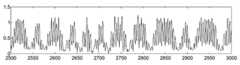
도 6은 도 1의 (c)에서 출력된 신호를 나타낸 시간-신호레벨의 그래프이다.FIG. 6 is a graph of time-signal levels showing the signals output in FIG.
도 1의 (c)에서 출력된 신호는 에지 신호(620)를 가리킨다. 에지 신호(620)는 오프셋 잡음에 의해 왜곡된 태그 신호(610)에 대하여, 도 6에 도시된 바와 같이 생성될 수 있다. 즉, 에지 신호(620)는 도 1의 (a) 및 (b) 단자에서 검출된 도 4, 5의 신호가 뺄셈기(도 1의 "131" 참조), 저역통과필터(도 1의 "132" 참조), 및 레벨 결정기(도 1의 "133" 참조)를 거쳐서 출력된 신호일 수 있다.The signal output in (c) of FIG. 1 indicates the
이러한 에지 신호(620)는 서브 캐리어 방식의 태그 신호에서 위상 반전이 일어나는 위치에 생길 수 있다. 에지 신호(620)는 에지 정보 추출부(도 1의 "140" 참조)로 전송되어, 에지 정보를 검출하는 데에 사용될 수 있다.The
도 7은 도 1의 에지 정보 추출부에 의해 추출된 에지 정보 및 에지 클럭을 나타낸 그래프이다.FIG. 7 is a graph illustrating edge information and an edge clock extracted by the edge information extractor of FIG. 1.
도 7에 도시된 바와 같이, 에지 정보 추출부(도 1의 "140" 참조)는 에지 신호(710)를 이용하여 에지 정보(720)를 추출할 수 있다. 상기 에지 정보 추출부는 상기 추출된 에지 정보(720)를 이용하여 에지 클럭(730)을 발생시킬 수 있다. 이에 따라, 디코딩부(도 1의 "150" 참조)는 상기 발생된 에지 클럭(730)을 이용하여 디코딩된 데이터(740)을 출력할 수 있다. 여기서, 상기 디코딩된 데이터(740)는 서브 캐리어가 제거된 태그 신호를 복조한 결과의 타이밍도를 나타낸 것이다.As illustrated in FIG. 7, the edge information extractor (see “140” of FIG. 1) may extract the
도 8은 본 발명의 실시예에 따른 서브 캐리어 방식의 태그 신호에 대한 RFID 리더의 복조 방법을 설명하기 위해 도시한 흐름도이다. 상기 복조 방법은 RFID 리더의 복조 장치에 의해 구현될 수 있다.8 is a flowchart illustrating a demodulation method of an RFID reader for a tag signal of a subcarrier type according to an embodiment of the present invention. The demodulation method may be implemented by a demodulation device of an RFID reader.
도 8을 참조하면, 먼저 상기 RFID 리더의 복조 장치는 밀러 서브캐리어(Miller sub-carrier) 신호에 대한 밴드패스 필터링을 수행하여, I 채널로 입력되는 태그 신호의 원하지 않는 저주파 및 고주파 성분과 잡음 성분 등을 제거한다. 그리고, 상기 RFID 리더의 복조 장치는 밀러 서브캐리어(Miller sub-carrier) 신호에 대한 밴드패스 필터링을 수행하여, Q 채널로 입력되는 태그 신호의 원하지 않는 저주파 및 고주파 성분과 잡음 성분 등을 제거한다.Referring to FIG. 8, first, the demodulation device of the RFID reader performs bandpass filtering on a Miller subcarrier signal, thereby causing unwanted low and high frequency components and noise components of a tag signal input to an I channel. Remove your back. In addition, the demodulation device of the RFID reader performs bandpass filtering on a Miller subcarrier signal to remove unwanted low and high frequency components and noise components of a tag signal input to the Q channel.
다음으로, 단계(S810)에서 상기 RFID 리더의 복조 장치는 서브 캐리어 방식의 태그 신호를 수신하여 상기 태그 신호에 대한 에지 신호를 생성한다. 이때, 상기 RFID 리더의 복조 장치는 상기 태그 신호로부터 위상 반전이 일어나는 위치를 검출하고, 상기 검출된 위치에 상기 에지 신호를 생성할 수 있다.Next, in step S810, the demodulation device of the RFID reader receives a tag signal of a subcarrier type and generates an edge signal for the tag signal. In this case, the demodulation device of the RFID reader may detect a position where phase reversal occurs from the tag signal and generate the edge signal at the detected position.
다음으로, 단계(S820)에서 상기 RFID 리더의 복조 장치는 상기 생성된 에지 신호로부터 에지 정보를 추출한다. 이때, 상기 RFID 리더의 복조 장치는 상기 생성된 에지 신호의 현재 샘플값과 적어도 하나의 이전 샘플값을 비교하여, 상기 에지 신호의 첨두점을 검출하고, 상기 검출된 첨두점을 이용하여 상기 에지 정보를 추출할 수 있다.Next, in step S820, the demodulation device of the RFID reader extracts edge information from the generated edge signal. In this case, the demodulation device of the RFID reader compares a current sample value of the generated edge signal with at least one previous sample value, detects a peak point of the edge signal, and uses the detected peak point to perform the edge information. Can be extracted.
다음으로, 단계(S830)에서 상기 RFID 리더의 복조 장치는 상기 추출된 에지 정보를 이용하여 에지 클럭을 생성한다.Next, in step S830, the demodulation device of the RFID reader generates an edge clock using the extracted edge information.
다음으로, 단계(S840)에서 상기 RFID 리더의 복조 장치는 상기 생성된 에지 클럭을 이용하여 비트 데이터를 결정한다.Next, in step S840, the demodulation device of the RFID reader determines bit data by using the generated edge clock.
다음으로, 단계(S850)에서 상기 RFID 리더의 복조 장치는 상기 결정된 비트 데이터를 이용하여 상기 태그 신호의 프리앰블을 검출한다.Next, in step S850, the demodulation device of the RFID reader detects the preamble of the tag signal using the determined bit data.
다음으로, 단계(S860)에서 상기 RFID 리더의 복조 장치는 상기 검출된 프리앰블을 이용하여 태그 신호를 디코딩한다.Next, in step S860, the demodulation device of the RFID reader decodes a tag signal using the detected preamble.
이와 같이, 상기 RFID 리더의 복조 장치는 서브 캐리어 방식의 태그 신호에 대해, 서브 캐리어가 제거된 에지 신호를 생성하고, 상기 생성된 에지 신호로부터 에지 정보를 추출하여 복조함으로써, 수신되는 태그 신호에 오프셋 왜곡 잡음이 발생하더라도 상기 태그 신호의 복조에 대한 신뢰성을 높일 수 있다.As described above, the demodulation device of the RFID interrogator generates an edge signal from which subcarriers are removed, and extracts and demodulates edge information from the generated edge signal, thereby offsetting the received tag signal. Even when distortion noise occurs, reliability of demodulation of the tag signal can be improved.
또한, 상기 RFID 리더의 복조 장치는 태그 신호의 변조 방식에 상관 없이, 수신되는 태그 신호에 대한 에지 신호 및 에지 성분(정보)를 추출하여 ASK(Amplitude Shift Keying) 또는 BPSK(Binary Phase Shift Keying) 방식으로 복조할 수 있다.In addition, the demodulation device of the RFID reader extracts an edge signal and an edge component (information) for a received tag signal, regardless of a modulation method of a tag signal, and uses Amplitude Shift Keying (ASK) or Binary Phase Shift Keying (BPSK). Can be demodulated by
또한, 상기 RFID 리더의 복조 장치는 복조 및 디코딩에 신호의 에지 성분(정보)을 이용하기 때문에, RFID 태그와 RFID 리더 간의 거리에 따른 위상이 변화하더라도 간단한 구조로 위상 다이버시티를 구현할 수 있도록 한다.In addition, since the demodulation device of the RFID reader uses edge components (information) of the signal for demodulation and decoding, even if the phase changes according to the distance between the RFID tag and the RFID reader, phase diversity can be implemented with a simple structure.
도 9는 본 발명의 실시예에 따라 에지 정보를 추출하는 알고리즘을 도시한 도면이다.9 is a diagram illustrating an algorithm for extracting edge information according to an embodiment of the present invention.
도 9를 참조하면, 단계(S910, S920)에서 상기 RFID 리더의 복조 장치는 상기 생성된 에지 신호의 현재 샘플값과 적어도 하나의 이전 샘플값을 비교하여, 상기 적어도 하나의 이전 샘플값 중, 상기 현재 샘플값과의 차가 최고인 값과 최저인 값을 각각 최고값(dx_high)과 최저값(dx_low)으로서 산출할 수 있다. 도 9의 단계(S910, 920)에서, dn은 1, 2, 3, ... n 등의 자연수일 수 있다. dn=1이면 바로 이전 샘플값을 의미하고, dn=2이면 현재 샘플보다 2샘플 전의 샘플값을 의미한다.Referring to FIG. 9, in steps S910 and S920, the demodulation device of the RFID interrogator compares a current sample value of the generated edge signal with at least one previous sample value, and among the at least one previous sample value. The highest and lowest values of the difference with the current sample value can be calculated as the highest value (dx_high) and the lowest value (dx_low), respectively. In steps S910 and 920 of FIG. 9, dn may be a natural number such as 1, 2, 3,... N. dn = 1 means the previous sample value, and dn = 2 means the sample value two samples before the current sample.
다음으로, 단계(S930)에서 상기 RFID 리더의 복조 장치는 상기 산출된 최고값과 최저값을 이용하여, 첨두점이 발생하는 조건을 만족하는지를 판단할 수 있다. 즉, 상기 RFID 리더의 복조 장치는 상기 최고값(dx_high)이 0보다 작거나 같고 상기 최소값(dx_low)이 0보다 큰 경우, 상기 첨두점이 발생하는 조건으로 판단할 수 있다. 다시 말해서, 상기 RFID 리더의 복조 장치는 상기 에지 신호의 기울기가 양에서 음으로 바뀌는 부분에서 상기 첨두점이 발생하는 것으로 판단할 수 있다.Next, in step S930, the demodulation device of the RFID reader may determine whether the peak point is satisfied using the calculated highest and lowest values. That is, the demodulation device of the RFID reader may determine that the peak occurs when the maximum value dx_high is less than or equal to zero and the minimum value dx_low is greater than zero. In other words, the demodulation device of the RFID reader may determine that the peak occurs at a portion where the slope of the edge signal changes from positive to negative.
다음으로, 단계(S940)에서 상기 RFID 리더의 복조 장치는 상기 첨두점이 발생하는 조건으로 판단되는 경우(S930의 "Yes" 방향), 상기 첨두점(n: 에지 정보 위치)을 검출할 수 있다.Next, the demodulation device of the RFID reader in step S940 may detect the peak point (n: edge information position) when it is determined that the peak point occurs (in the "Yes" direction of S930).
다음으로, 단계(S950)에서 상기 RFID 리더의 복조 장치는 상기 첨두점(n)을 이용하여 에지 정보를 추출할 수 있다. 즉, 상기 RFID 리더의 복조 장치는 상기 첨두점(n)에 해당하는 이전 샘플로부터 상기 에지 정보를 추출할 수 있다.Next, in step S950, the demodulation device of the RFID reader may extract edge information using the peak point n. That is, the demodulation device of the RFID reader may extract the edge information from the previous sample corresponding to the peak point n.
본 발명의 실시예들은 다양한 컴퓨터로 구현되는 동작을 수행하기 위한 프로 그램 명령을 포함하는 컴퓨터 판독 가능 매체를 포함한다. 상기 컴퓨터 판독 가능 매체는 프로그램 명령, 로컬 데이터 파일, 로컬 데이터 구조 등을 단독으로 또는 조합하여 포함할 수 있다. 상기 매체는 본 발명을 위하여 특별히 설계되고 구성된 것들이거나 컴퓨터 소프트웨어 당업자에게 공지되어 사용 가능한 것일 수도 있다. 컴퓨터 판독 가능 기록 매체의 예에는 하드 디스크, 플로피 디스크 및 자기 테이프와 같은 자기 매체, CD-ROM, DVD와 같은 광기록 매체, 플롭티컬 디스크와 같은 자기-광 매체, 및 롬, 램, 플래시 메모리 등과 같은 프로그램 명령을 저장하고 수행하도록 특별히 구성된 하드웨어 장치가 포함된다. 프로그램 명령의 예에는 컴파일러에 의해 만들어지는 것과 같은 기계어 코드뿐만 아니라 인터프리터 등을 사용해서 컴퓨터에 의해서 실행될 수 있는 고급 언어 코드를 포함한다.Embodiments of the present invention include computer readable media containing program instructions for performing various computer-implemented operations. The computer readable medium may include program instructions, local data files, local data structures, or the like, alone or in combination. The media may be those specially designed and constructed for the purposes of the present invention, or they may be of the kind well-known and available to those having skill in the computer software arts. Examples of computer-readable recording media include magnetic media such as hard disks, floppy disks, and magnetic tape, optical recording media such as CD-ROMs, DVDs, magnetic-optical media such as floppy disks, and ROM, RAM, flash memory, and the like. Hardware devices specifically configured to store and execute the same program instructions are included. Examples of program instructions include not only machine code generated by a compiler, but also high-level language code that can be executed by a computer using an interpreter or the like.
지금까지 본 발명에 따른 구체적인 실시예에 관하여 설명하였으나, 본 발명의 범위에서 벗어나지 않는 한도 내에서는 여러 가지 변형이 가능함은 물론이다. 그러므로, 본 발명의 범위는 설명된 실시예에 국한되어 정해져서는 안 되며, 후술하는 특허 청구의 범위뿐 아니라 이 특허 청구의 범위와 균등한 것들에 의해 정해져야 한다.While specific embodiments of the present invention have been described so far, various modifications are possible without departing from the scope of the present invention. Therefore, the scope of the present invention should not be limited to the described embodiments, but should be determined not only by the claims below, but also by the equivalents of the claims.
이상과 같이 본 발명은 비록 한정된 실시예와 도면에 의해 설명되었으나, 본 발명은 상기의 실시예에 한정되는 것은 아니며, 이는 본 발명이 속하는 분야에서 통상의 지식을 가진 자라면 이러한 기재로부터 다양한 수정 및 변형이 가능하다. 따라서, 본 발명 사상은 아래에 기재된 특허청구범위에 의해서만 파악되어야 하고, 이의 균등 또는 등가적 변형 모두는 본 발명 사상의 범주에 속한다고 할 것이다.As described above, the present invention has been described by way of limited embodiments and drawings, but the present invention is not limited to the above-described embodiments, which can be variously modified and modified by those skilled in the art to which the present invention pertains. Modifications are possible. Accordingly, the spirit of the present invention should be understood only by the claims set forth below, and all equivalent or equivalent modifications thereof will belong to the scope of the present invention.
도 1은 본 발명의 실시예에 따른 서브 캐리어 방식의 태그 신호에 대한 RFID 리더의 복조 장치를 설명하기 위해 도시한 블록도이다.1 is a block diagram illustrating a demodulation device of an RFID reader for a tag signal of a subcarrier type according to an embodiment of the present invention.
도 2는 도 1의 I 및 Q 채널의 정합 필터 1을 나타낸 그래프이다.FIG. 2 is a graph illustrating matched
도 3은 도 1의 I 및 Q 채널의 정합 필터 2를 나타낸 그래프이다.3 is a graph illustrating matched
도 4는 도 1의 (a)에서 출력된 신호를 나타낸 시간-신호레벨의 그래프이다.FIG. 4 is a graph of time-signal levels showing the signal output in FIG.
도 5는 도 1의 (b)에서 출력된 신호를 나타낸 시간-신호레벨의 그래프이다.FIG. 5 is a graph of time-signal levels showing the signal output in FIG.
도 6은 도 1의 (c)에서 출력된 신호를 나타낸 시간-신호레벨의 그래프이다.FIG. 6 is a graph of time-signal levels showing the signals output in FIG.
도 7은 도 1의 에지 정보 추출부에 의해 추출된 에지 정보 및 에지 클럭을 나타낸 그래프이다.FIG. 7 is a graph illustrating edge information and an edge clock extracted by the edge information extractor of FIG. 1.
도 8은 본 발명의 실시예에 따른 서브 캐리어 방식의 태그 신호에 대한 RFID 리더의 복조 방법을 설명하기 위해 도시한 흐름도이다.8 is a flowchart illustrating a demodulation method of an RFID reader for a tag signal of a subcarrier type according to an embodiment of the present invention.
도 9는 본 발명의 실시예에 따라 에지 정보를 추출하는 알고리즘을 도시한 도면이다.9 is a diagram illustrating an algorithm for extracting edge information according to an embodiment of the present invention.
<도면의 주요 부분에 대한 부호의 설명><Explanation of symbols for the main parts of the drawings>
110: 디지털 필터 111: I 채널 디지털 필터110: digital filter 111: I channel digital filter
112: Q 채널 디지털 필터 120: 에지 신호 생성부112: Q channel digital filter 120: edge signal generator
121: I 채널 정합 필터 1 122: I 채널 정합 필터 2121: I channel matched
123: Q 채널 정합 필터 1 124: Q 채널 정합 필터 2123: Q channel matched
125: I 채널 절대기 1 126: I 채널 절대기 2125: I channel absolute 1 126: I channel absolute 2
127: Q 채널 절대기 1 128: Q 채널 절대기 2127: Q channel absolute 2 1 128: Q channel absolute 2
129: I 채널 합산기 130: Q 채널 합산기129: I channel summer 130: Q channel summer
131: 뺄셈기 132: 저역통과필터131: subtractor 132: low pass filter
133: 레벨 결정기 140: 에지 신호 추출부133: level determiner 140: edge signal extractor
141: 에지 클럭 발생부 150: 디코딩부141: edge clock generator 150: decoder
151: 비트 데이터 결정기 152: 프리앰블 검출기151: bit data determiner 152: preamble detector
Claims (10)
Translated fromKoreanPriority Applications (2)
| Application Number | Priority Date | Filing Date | Title |
|---|---|---|---|
| KR1020080079337AKR100957700B1 (en) | 2008-08-13 | 2008-08-13 | RDF Reader Demodulation Apparatus and Method for Subcarrier Tag Signals |
| US12/348,529US8264332B2 (en) | 2008-08-13 | 2009-01-05 | Apparatus and method for demodulating subcarrier tag signal in RFID reader |
Applications Claiming Priority (1)
| Application Number | Priority Date | Filing Date | Title |
|---|---|---|---|
| KR1020080079337AKR100957700B1 (en) | 2008-08-13 | 2008-08-13 | RDF Reader Demodulation Apparatus and Method for Subcarrier Tag Signals |
Publications (2)
| Publication Number | Publication Date |
|---|---|
| KR20100020655A KR20100020655A (en) | 2010-02-23 |
| KR100957700B1true KR100957700B1 (en) | 2010-05-12 |
Family
ID=41680940
Family Applications (1)
| Application Number | Title | Priority Date | Filing Date |
|---|---|---|---|
| KR1020080079337AExpired - Fee RelatedKR100957700B1 (en) | 2008-08-13 | 2008-08-13 | RDF Reader Demodulation Apparatus and Method for Subcarrier Tag Signals |
Country Status (2)
| Country | Link |
|---|---|
| US (1) | US8264332B2 (en) |
| KR (1) | KR100957700B1 (en) |
Families Citing this family (6)
| Publication number | Priority date | Publication date | Assignee | Title |
|---|---|---|---|---|
| KR20120025747A (en)* | 2010-09-08 | 2012-03-16 | 한국전자통신연구원 | Method and apparatus of a passive radio frequency identification reader digital demodulation for manchester subcarrier signal |
| KR20120050087A (en)* | 2010-11-10 | 2012-05-18 | 한국전자통신연구원 | Method and apparatus of rfid tag collision detection |
| US9461852B2 (en)* | 2014-11-20 | 2016-10-04 | Mediatek Singapore Pte. Ltd. | Signal demodulation apparatus and signal demodulation method |
| CN114070690B (en)* | 2021-11-25 | 2023-09-26 | 北京紫光青藤微系统有限公司 | Non-contact card machine, noise processing method and device |
| KR102499235B1 (en)* | 2022-09-27 | 2023-02-13 | 주식회사 황금휘날레 | How to Read RFID Based on Android |
| KR102518315B1 (en)* | 2022-09-27 | 2023-04-05 | 주식회사 황금휘날레 | Android-based RFID reader solution system |
Citations (2)
| Publication number | Priority date | Publication date | Assignee | Title |
|---|---|---|---|---|
| KR100768100B1 (en) | 2005-09-29 | 2007-10-17 | 한국전자통신연구원 | Appratus and Method for Receiving Tag Signal in Mobile RFID Reader |
| KR100771487B1 (en) | 2006-08-07 | 2007-10-30 | 주식회사 파이칩스 | Method and apparatus for signal decoding in radio wave identification system |
Family Cites Families (7)
| Publication number | Priority date | Publication date | Assignee | Title |
|---|---|---|---|---|
| CN1155964C (en)* | 1999-03-02 | 2004-06-30 | 松下电器产业株式会社 | Digital audio interface signal demodulating device |
| JP4416351B2 (en)* | 2001-04-18 | 2010-02-17 | 富士通株式会社 | Phase comparison circuit and optical receiver |
| US7026935B2 (en)* | 2003-11-10 | 2006-04-11 | Impinj, Inc. | Method and apparatus to configure an RFID system to be adaptable to a plurality of environmental conditions |
| FR2877520A1 (en)* | 2004-11-04 | 2006-05-05 | St Microelectronics Sa | Encoded binary data signal decoding and clock signal generating method, involves generating binary clock signal from edge detection signal, where clock signal is synchronous with encoded data signal |
| EP1929426B1 (en)* | 2005-09-09 | 2011-03-16 | Nxp B.V. | Rfid signal reading method with delimiter pattern detection |
| KR100765204B1 (en) | 2006-05-03 | 2007-10-09 | 이선규 | Demodulation system |
| US7742547B2 (en)* | 2006-12-05 | 2010-06-22 | Industrial Technology Research Institute | Method and system for reading RFID tags |
- 2008
- 2008-08-13KRKR1020080079337Apatent/KR100957700B1/ennot_activeExpired - Fee Related
- 2009
- 2009-01-05USUS12/348,529patent/US8264332B2/ennot_activeExpired - Fee Related
Patent Citations (2)
| Publication number | Priority date | Publication date | Assignee | Title |
|---|---|---|---|---|
| KR100768100B1 (en) | 2005-09-29 | 2007-10-17 | 한국전자통신연구원 | Appratus and Method for Receiving Tag Signal in Mobile RFID Reader |
| KR100771487B1 (en) | 2006-08-07 | 2007-10-30 | 주식회사 파이칩스 | Method and apparatus for signal decoding in radio wave identification system |
Also Published As
| Publication number | Publication date |
|---|---|
| US8264332B2 (en) | 2012-09-11 |
| US20100039227A1 (en) | 2010-02-18 |
| KR20100020655A (en) | 2010-02-23 |
Similar Documents
| Publication | Publication Date | Title |
|---|---|---|
| KR100957700B1 (en) | RDF Reader Demodulation Apparatus and Method for Subcarrier Tag Signals | |
| US7917088B2 (en) | Adaptable detection threshold for RFID tags and chips | |
| JP4676357B2 (en) | Quadrature demodulator and interrogator | |
| US20120057656A1 (en) | Method and apparatus for passive radio frequency indentification (rfid) reader digital demodulation for manchester subcarrier signal | |
| US20110215158A1 (en) | Passive RFID Transponder and RFID Reader | |
| CN107301360A (en) | Radio-frequency identification transponder and the method for sending radio frequency identification message | |
| US20080272892A1 (en) | Sampling to obtain signal from RFID card | |
| BR9915115A (en) | Procedure for ask demodulation and demodulator-ask | |
| KR101220178B1 (en) | Symbol synchronization apparatus and method of a passive RFID reader | |
| CN105515753B (en) | A kind of RFID lead code detecting method based on FPGA | |
| US20200235968A1 (en) | Communication device and method for receiving data via a radio signal | |
| KR100876284B1 (en) | Tag Signal Receiving Method in Rfid Reader and Tag Signal Receiving System in Rfid Reader | |
| US8120466B2 (en) | Decoding scheme for RFID reader | |
| JP4909410B2 (en) | Method for demodulating a modulated signal, demodulator and receiver | |
| US20140086292A1 (en) | Systems and methods for detecting data collisions for a near field communication system | |
| KR100943766B1 (en) | Offset distortion canceling method, tag signal receiving method and apparatus | |
| EP2329591B1 (en) | Data processing system | |
| KR101237974B1 (en) | RFID tag, RFID reader, and RFID system therewith | |
| CN103336978B (en) | A kind of RFID label tag radio-frequency fingerprint Verification System | |
| CN110649941B (en) | Method for recognizing noise by non-contact card reader | |
| EP3562111B1 (en) | Bit synchronization for on/off key (ook) communication | |
| KR101182837B1 (en) | Apparatus and Method for RFID reader demodulator | |
| KR20220093667A (en) | Digital modulated signal receiver and signal processing method of the same | |
| CN109698804B (en) | Demodulation module, demodulation circuit and high-frequency card reader | |
| KR100898704B1 (en) | RGB reader and its demodulation method |
Legal Events
| Date | Code | Title | Description |
|---|---|---|---|
| A201 | Request for examination | ||
| PA0109 | Patent application | St.27 status event code:A-0-1-A10-A12-nap-PA0109 | |
| PA0201 | Request for examination | St.27 status event code:A-1-2-D10-D11-exm-PA0201 | |
| PN2301 | Change of applicant | St.27 status event code:A-3-3-R10-R11-asn-PN2301 St.27 status event code:A-3-3-R10-R13-asn-PN2301 | |
| PG1501 | Laying open of application | St.27 status event code:A-1-1-Q10-Q12-nap-PG1501 | |
| D13-X000 | Search requested | St.27 status event code:A-1-2-D10-D13-srh-X000 | |
| D14-X000 | Search report completed | St.27 status event code:A-1-2-D10-D14-srh-X000 | |
| E701 | Decision to grant or registration of patent right | ||
| PE0701 | Decision of registration | St.27 status event code:A-1-2-D10-D22-exm-PE0701 | |
| GRNT | Written decision to grant | ||
| PR0701 | Registration of establishment | St.27 status event code:A-2-4-F10-F11-exm-PR0701 | |
| PR1002 | Payment of registration fee | Fee payment year number:1 St.27 status event code:A-2-2-U10-U11-oth-PR1002 | |
| PG1601 | Publication of registration | St.27 status event code:A-4-4-Q10-Q13-nap-PG1601 | |
| L13-X000 | Limitation or reissue of ip right requested | St.27 status event code:A-2-3-L10-L13-lim-X000 | |
| U15-X000 | Partial renewal or maintenance fee paid modifying the ip right scope | St.27 status event code:A-4-4-U10-U15-oth-X000 | |
| FPAY | Annual fee payment | Payment date:20130424 Year of fee payment:4 | |
| PR1001 | Payment of annual fee | Fee payment year number:4 St.27 status event code:A-4-4-U10-U11-oth-PR1001 | |
| PN2301 | Change of applicant | St.27 status event code:A-5-5-R10-R11-asn-PN2301 | |
| PN2301 | Change of applicant | St.27 status event code:A-5-5-R10-R14-asn-PN2301 | |
| FPAY | Annual fee payment | Payment date:20140415 Year of fee payment:5 | |
| PR1001 | Payment of annual fee | Fee payment year number:5 St.27 status event code:A-4-4-U10-U11-oth-PR1001 | |
| P14-X000 | Amendment of ip right document requested | St.27 status event code:A-5-5-P10-P14-nap-X000 | |
| P16-X000 | Ip right document amended | St.27 status event code:A-5-5-P10-P16-nap-X000 | |
| Q16-X000 | A copy of ip right certificate issued | St.27 status event code:A-4-4-Q10-Q16-nap-X000 | |
| PN2301 | Change of applicant | St.27 status event code:A-5-5-R10-R11-asn-PN2301 St.27 status event code:A-5-5-R10-R13-asn-PN2301 | |
| FPAY | Annual fee payment | Payment date:20150427 Year of fee payment:6 | |
| PR1001 | Payment of annual fee | Fee payment year number:6 St.27 status event code:A-4-4-U10-U11-oth-PR1001 | |
| FPAY | Annual fee payment | Payment date:20160504 Year of fee payment:7 | |
| PR1001 | Payment of annual fee | Fee payment year number:7 St.27 status event code:A-4-4-U10-U11-oth-PR1001 | |
| PC1903 | Unpaid annual fee | Not in force date:20170505 Payment event data comment text:Termination Category : DEFAULT_OF_REGISTRATION_FEE St.27 status event code:A-4-4-U10-U13-oth-PC1903 | |
| PC1903 | Unpaid annual fee | Ip right cessation event data comment text:Termination Category : DEFAULT_OF_REGISTRATION_FEE Not in force date:20170505 St.27 status event code:N-4-6-H10-H13-oth-PC1903 | |
| P22-X000 | Classification modified | St.27 status event code:A-4-4-P10-P22-nap-X000 | |
| P22-X000 | Classification modified | St.27 status event code:A-4-4-P10-P22-nap-X000 |