KR100957366B1 - Jig device for joining equipment for fuel cell stack separator - Google Patents
Jig device for joining equipment for fuel cell stack separatorDownload PDFInfo
- Publication number
- KR100957366B1 KR100957366B1KR1020080023305AKR20080023305AKR100957366B1KR 100957366 B1KR100957366 B1KR 100957366B1KR 1020080023305 AKR1020080023305 AKR 1020080023305AKR 20080023305 AKR20080023305 AKR 20080023305AKR 100957366 B1KR100957366 B1KR 100957366B1
- Authority
- KR
- South Korea
- Prior art keywords
- separator
- plate
- fuel cell
- cell stack
- jig device
- Prior art date
- Legal status (The legal status is an assumption and is not a legal conclusion. Google has not performed a legal analysis and makes no representation as to the accuracy of the status listed.)
- Expired - Fee Related
Links
Images


Classifications
- H—ELECTRICITY
- H01—ELECTRIC ELEMENTS
- H01M—PROCESSES OR MEANS, e.g. BATTERIES, FOR THE DIRECT CONVERSION OF CHEMICAL ENERGY INTO ELECTRICAL ENERGY
- H01M8/00—Fuel cells; Manufacture thereof
- H01M8/02—Details
- H01M8/0202—Collectors; Separators, e.g. bipolar separators; Interconnectors
- H01M8/0204—Non-porous and characterised by the material
- H01M8/0223—Composites
- H01M8/0228—Composites in the form of layered or coated products
- H—ELECTRICITY
- H01—ELECTRIC ELEMENTS
- H01M—PROCESSES OR MEANS, e.g. BATTERIES, FOR THE DIRECT CONVERSION OF CHEMICAL ENERGY INTO ELECTRICAL ENERGY
- H01M8/00—Fuel cells; Manufacture thereof
- H01M8/02—Details
- H01M8/0202—Collectors; Separators, e.g. bipolar separators; Interconnectors
- H01M8/0204—Non-porous and characterised by the material
- H01M8/0206—Metals or alloys
- Y—GENERAL TAGGING OF NEW TECHNOLOGICAL DEVELOPMENTS; GENERAL TAGGING OF CROSS-SECTIONAL TECHNOLOGIES SPANNING OVER SEVERAL SECTIONS OF THE IPC; TECHNICAL SUBJECTS COVERED BY FORMER USPC CROSS-REFERENCE ART COLLECTIONS [XRACs] AND DIGESTS
- Y02—TECHNOLOGIES OR APPLICATIONS FOR MITIGATION OR ADAPTATION AGAINST CLIMATE CHANGE
- Y02E—REDUCTION OF GREENHOUSE GAS [GHG] EMISSIONS, RELATED TO ENERGY GENERATION, TRANSMISSION OR DISTRIBUTION
- Y02E60/00—Enabling technologies; Technologies with a potential or indirect contribution to GHG emissions mitigation
- Y02E60/30—Hydrogen technology
- Y02E60/50—Fuel cells
Landscapes
- Chemical & Material Sciences (AREA)
- Life Sciences & Earth Sciences (AREA)
- Engineering & Computer Science (AREA)
- Manufacturing & Machinery (AREA)
- Sustainable Development (AREA)
- Sustainable Energy (AREA)
- Chemical Kinetics & Catalysis (AREA)
- Electrochemistry (AREA)
- General Chemical & Material Sciences (AREA)
- Composite Materials (AREA)
- Fuel Cell (AREA)
Abstract
Translated fromKoreanDescription
Translated fromKorean본 발명은 연료전지 스택 분리판용 접합설비의 지그장치에 관한 것으로, 더욱 상세하게는 연료전지 스택의 분리판을 접합하는 설비에서 실란트 도포부위 및 용접지점과의 간섭이 발생하지 않도록 분리판을 클램핑하는 지그장치에 관한 것이다.The present invention relates to a jig device for a bonding device for a fuel cell stack separator, and more particularly, to clamp a separator so that interference with a sealant coating site and a welding point does not occur in a facility for joining a separator plate of a fuel cell stack. It relates to a jig device.
일반적으로 연료전지 스택이란 단위셀을 반복적으로 적층하여 쌓은 전기 에너지 발생 장치를 말하는데, 이때, 단위셀은 수소와 산소가 반응하여 전기 에너지를 발생시키기 위한 최소한의 연료전지 구성요소이다.In general, a fuel cell stack refers to an electric energy generating device that is stacked by repeatedly stacking unit cells. In this case, the unit cell is a minimum fuel cell component for generating electric energy by reacting hydrogen and oxygen.
이러한 단위셀 구조는 최외곽부터 중심까지 끝단, 집전체, 분리판, 가스 확산층(GDL), 전극촉매, 양자 교환막 순으로 적층된다.The unit cell structure is stacked from the outermost to the center end, the current collector, the separator, the gas diffusion layer (GDL), the electrode catalyst, and the proton exchange membrane.
여기서, 상기 분리판은 상판과 하판 사이에 액상 실란트가 도포되어 접합되며, 연료전지의 연료가 되는 수소 및 공기(산소), 냉각수의 공급을 위하여 표면에 유로가 가공되고, 전기를 전달할 수 있도록 흑연 또는 금속으로 제작된다.Here, the separator is bonded to the liquid sealant between the upper plate and the lower plate is bonded, and the flow path is processed on the surface for supplying hydrogen and air (oxygen) and cooling water as fuel of the fuel cell, graphite to transfer electricity Or made of metal.
분리판을 제작하는 공정에서 수소 및 공기(산소), 냉각수 유로간에 기밀을 위해 하판에 불소계 고무로 된 실란트(sealant)를 액체상태로 도포하며, 그 위에 상판을 로딩하여 스폿(spot) 용접 후 고온경화시킴으로써 제작이 완료된다.In the process of manufacturing the separating plate, sealant made of fluorine rubber sealant is applied to the lower plate in a liquid state for airtight between hydrogen, air (oxygen) and cooling water flow path, and the upper plate is loaded thereon, followed by high temperature after spot welding. Production is completed by hardening.
상기와 같이 연료전지 스택의 분리판을 제작하기 위해 소재를 클램핑하여 실란트를 도포하고 용접작업을 완료한 다음, 제작 완료된 분리판의 기밀 테스트를 할 수 있도록 구성된 종래 연료전지 스택 분리판용 접합설비가 마련된다.In order to manufacture a separator of the fuel cell stack as described above, a bonding apparatus for a conventional fuel cell stack separator is provided, which is configured to apply a sealant by applying a sealant, complete a welding operation, and perform an airtight test of the manufactured separator. do.
그러나, 종래 연료전지 스택 분리판용 접합설비에서 소재를 공급하여 클램핑하도록 구성되는 지그장치는, 각 공정간에 소재를 운반하는 과정에서 상기 분리판에 가해지는 클램핑력에 의해 평탄도가 저하되는 문제가 있다.However, the jig device configured to supply and clamp a material in a conventional fuel cell stack bonding device has a problem in that flatness is lowered due to the clamping force applied to the separator in the process of transporting the material between the processes. .
또한, 상기 분리판을 클램핑하는데 있어서 실란트 도포부위 및 용접지점과 간섭이 발생함으로 인한 수정 작업에 많은 시간이 소요되는 문제점도 있다.In addition, in the clamping of the separator there is also a problem that takes a lot of time to correct the work due to the interference with the sealant coating site and the welding point.
본 발명은 상기와 같은 문제점을 해결하기 위해 발명한 것으로서, 연료전지 스택의 분리판을 접합제작하는데 있어서, 분리판의 형상과 실란트 도포부위 및 용접지점의 위치를 고려하여 클램핑하도록 구성함으로써 실란트 도포부위 및 용접지점과의 간섭을 제거할 수 있는 연료전지 스택 분리판용 접합설비의 지그장치를 제공하는데 그 목적이 있다.The present invention has been invented to solve the above problems, in the manufacture of the junction plate of the fuel cell stack, the sealant application site by configuring to clamp in consideration of the shape of the separator plate and the position of the sealant application site and the welding point. And to provide a jig device of the bonding equipment for the fuel cell stack separator that can eliminate the interference with the welding point.
상기한 목적을 달성하기 위해 본 발명은 상판과 하판으로 구성되어 유로가 형성되는 연료전지 스택의 분리판을 접합하기 위한 접합설비의 지그장치에 있어서,In order to achieve the above object, the present invention is a jig device of the bonding facility for joining the separator plate of the fuel cell stack is composed of the upper plate and the lower plate, the flow path is formed,
소재가 공급되어 안착되는 분리판 공급부가 회전력을 공급하는 구동수단에 축설되며, 상기 분리판 공급부의 회전으로 인해 이송되는 소재가 안착되는 분리판 클램핑부가 실란트 도포부위 및 용접지점과의 간섭없이 상기 소재의 외곽 모서리를 클램핑하도록 구성되는 것을 특징으로 하는 연료전지 스택 분리판용 접합설비의 지그장치를 제공한다.The separator plate supplying material is placed on the driving means for supplying the rotational force, and the separator plate clamping part for the material being transported due to the rotation of the separator plate supplying part is installed without interference with the sealant coating site and the welding point. It provides a jig device of the bonding equipment for the fuel cell stack separator, characterized in that configured to clamp the outer edge of the.
바람직하게, 상기 분리판 클램핑부는 부착된 핑거의 기립으로 회전운동하는 회전축과, 상기 회전축의 회전운동으로 하강되는 클램핑 바와, 상기 회전축에 설치되어 회전축의 회전운동으로 오픈되는 박판 스프링을 포함하여 구성되고;Preferably, the separating plate clamping portion is configured to include a rotary shaft to rotate in the standing position of the finger attached, a clamping bar lowered by the rotary movement of the rotary shaft, a thin plate spring is installed on the rotary shaft and opened by the rotary movement of the rotary shaft, ;
상기 분리판 공급부는 소재를 정위치로 가이드하는 위치결정핀과, 상기 소재를 진공흡착하는 진공흡착패드와, 회전운동으로 인해 상기 핑거를 누름동작하는 푸셔를 포함하여 구성되는 것을 특징으로 한다.The separating plate supply unit is characterized in that it comprises a positioning pin for guiding the material to the correct position, a vacuum suction pad for vacuum suction of the material, and a pusher for pressing the finger due to the rotational movement.
그리고, 상기 분리판 공급부의 복귀에 따라 하단에 연설된 스프링에 의해 상승되는 클램핑 바와, 상기 클램핑 바의 상승으로 소재를 클램핑하는 박판 스프링으로 구성되는 것을 특징으로 한다.And, it is characterized in that it consists of a clamping bar which is raised by a spring protruded at the bottom in accordance with the return of the separator plate supply portion, and a leaf spring clamping the material by the rising of the clamping bar.
더욱 바람직하게, 상기 분리판 클램핑부는 이송된 소재를 정위치로 가이드하는 위치결정핀이 더 포함되어 장착되는 것을 특징으로 한다.More preferably, the separating plate clamping portion is characterized in that the mounting pin further includes a guide for guiding the conveyed material in place.
본 발명에 따른 연료전지 스택 분리판용 접합설비의 지그장치는 공급되는 소재의 외곽 모서리를 클램핑하여 실란트 도포부위 및 용접지점과의 간섭을 방지할 수 있는 효과가 있다.The jig device of the fuel cell stack separator according to the present invention has the effect of preventing the interference with the sealant coating site and the welding point by clamping the outer edge of the supplied material.
그리고, 소재를 클램핑하기 위하여 박판 스프링을 적용함으로써 분리판의 평탄도를 확보할 수 있으며, 박판 스프링의 탈착이 가능하여 개별 교환으로 교체비용이 절감되는 효과도 있다.In addition, by applying a thin plate spring to clamp the material, it is possible to secure the flatness of the separator plate, it is possible to remove the thin plate spring has the effect of reducing the replacement cost by individual replacement.
분리판 공급부의 회전과 동시에 클램핑 및 언클램핑이 자동으로 이루어지기 때문에 클램핑을 위한 별도의 구동장치가 필요 없으며, 작업 사이클 타임이 단축되어 조립작업의 효율성을 향상시킬 수 있는 효과도 있다.Since the clamping and unclamping is automatically performed simultaneously with the rotation of the separator plate, there is no need for a separate driving device for clamping, and the work cycle time is shortened, thereby improving the efficiency of assembly work.
본 출원에서 사용한 용어는 단지 특정한 실시 예를 설명하기 위해 사용된 것으로, 본 발명을 한정하려는 의도가 아니며, 단수의 표현은 문맥상 명백하게 다르게 뜻하지 않는 한 복수의 표현을 포함한다.The terminology used herein is for the purpose of describing particular example embodiments only and is not intended to be limiting of the invention, and the singular forms “a”, “an” and “the” include plural forms unless the context clearly indicates otherwise.
또한, 본 발명의 실시 예로는 다수 개가 존재할 수 있으며, 설명에 사용되는 도면에 있어서, 종래의 기술과 동일한 부분에 대하여 중복되는 설명은 생략되는 것도 있다.In addition, there may be a plurality of embodiments of the present invention, and in the drawings used for description, overlapping description of the same parts as in the prior art may be omitted.
이하, 첨부된 도면을 참조로 하여 본 발명의 바람직한 일실시 예를 상세하게 설명한다.Hereinafter, with reference to the accompanying drawings will be described in detail a preferred embodiment of the present invention.
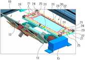
첨부한 도 1은 본 발명에 따라 바람직하게 구현된 지그장치가 포함되는 연료전지 스택 분리판용 접합설비를 도시한 사시도이고, 도 2는 본 발명에 따라 바람직하게 구현된 연료전지 스택 분리판용 접합설비의 지그장치를 도시한 구성 사시도, 도 3a~ 도 3e는 본 발명에 따른 지그장치의 동작과정을 도시한 상태도이다.1 is a perspective view illustrating a bonding apparatus for a fuel cell stack separator including a jig device preferably implemented according to the present invention, and FIG. 2 is a bonding apparatus for a fuel cell stack separator preferably implemented according to the present invention. 3A to 3E are state diagrams illustrating an operation process of the jig device according to the present invention.
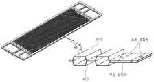
또한, 도 4는 분리판의 구성을 도시한 개략도이고, 도 5는 분리판의 제작공정을 도시한 개략도, 도 6은 본 발명에 따라 실란트 도보부위 및 용접지점을 고려하여 소재의 외곽 모서리만 클램핑한 상태를 개략적으로 도시한 평면도이다.In addition, Figure 4 is a schematic diagram showing the configuration of the separator plate, Figure 5 is a schematic diagram showing the manufacturing process of the separator plate, Figure 6 is clamping only the outer edge of the material in consideration of the sealant walking portion and the welding point in accordance with the present invention A plan view schematically showing one state.
본 발명에 따라 바람직하게 구현된 연료전지 스택 분리판용 접합설비의 지그장치는, 연료전지 스택의 분리판을 접합제작하는 접합장치에서 소재(상판과 하판)를 공급하여 클램핑하는 장치로서, 상기 분리판의 평탄도를 확보하고, 실란트 도포부위 및 용접지점과의 간섭없이 소재를 클램핑할 수 있다.According to the present invention, a jig device for a fuel cell stack separator is preferably an apparatus for supplying and clamping a material (upper plate and lower plate) in a bonding device for joining and manufacturing a separator plate of a fuel cell stack. Flatness can be secured and the material can be clamped without interference with the sealant application site and the welding point.
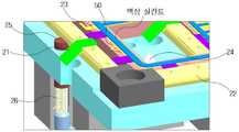
이를 위하여, 본 발명에 따른 지그장치는 도 2에 도시된 바와 같이 크게 분리판 공급부(10)와 분리판 클램핑부(20)로 구성되며, 이는 로터리 실린더(15), 진공흡착패드(12), 푸셔(pusher)(13), 위치결정핀(11,24), 박판 스프링(23), 회전축(22), 핑거(21), 클램핑 바(25) 등을 포함하여 구성된다.To this end, the jig device according to the present invention is largely composed of a separator
상기 분리판은 도 4에 도시된 바와 같이 금속 재질로 이루어진 상판과 하판 사이에 액상 실란트가 도포되어 구성된다.As shown in FIG. 4, a liquid sealant is applied between an upper plate and a lower plate made of a metal material, as shown in FIG. 4.
본 발명에 따른 지그장치를 포함하여 구성되는 연료전지 스택 분리판용 접합설비는, 도 1에 도시된 바와 같이, 실란트 도포 및 용접부(30)와 기밀 테스트 부(40)를 포함하여 구성된다.As shown in FIG. 1, the bonding apparatus for a fuel cell stack separator including the jig device according to the present invention includes a sealant coating and
상기 실란트 도포 및 용접부(30)는 2축 정밀 직교로봇과 실란트 도포 밸브, 마이크로 서보 용접기 등으로 구성되며, 상기 실란트 도포 밸브와 마이크로 서보 용접기를 상기 직교로봇에 장착하여 실란트 도포 및 용접작업이 이루어진다.The sealant coating and
또한, 상기 기밀 테스트부(40)는 실란트 도포 및 용접이 완료된 분리판을 가압하기 위한 프레스와 기밀 테스트를 위한 기밀 테스터기로 구성되며, 분리판 상판과 하판 사이에 누설량을 측정하여 실란트 도포 성능을 검사한다.In addition, the
이하, 본 발명에 따라 상기 분리판 공급부(10)와 분리판 클램핑부(20)로 구성되는 지그장치의 일실시 예를 더욱 상세하게 설명하면 다음과 같다.Hereinafter, an embodiment of a jig device composed of the separator
도 2에 도시된 바와 같이, 상기 로터리 실린더(15)는 작업자에 의해 공급되는 소재(상판 또는 하판)(50)가 안착되는 분리판 공급부(10)와 소재를 클램핑하는 분리판 클램핑부(20) 사이에 구성되어 공기로 동작되며, 축설된 상기 분리판 공급부(10)를 180°회전시켜 분리판 클램핑부(20)로 상기 소재(50)를 이송가능하게 하는 구동수단으로 구성된다.As shown in FIG. 2, the
상기 분리판 공급부(10)와 분리판 클램핑부(20)에 각각 구성되는 위치결정핀(11)은, 작업자에 의해 수작업으로 공급되는 소재(50)가 상기 분리판 공급부(10) 및 분리판 클램핑부(20)의 정위치에 위치할 수 있도록 가이드하는 역할을 한다.The
첨부한 도 2와 같이, 상기 분리판 공급부(10)에는 상기 위치결정핀(11)과 함께 진공흡착패드(12), 푸셔(13) 등이 설치되며, 상기 진공흡착패드(12)는 하단부에 장착되는 에어튜브(미도시)를 통해 진공발생장치(미도시)와 연결되어 외기를 흡수 하고 이로써 상기 분리판 공급부(10)의 회전시 소재(50)가 이탈되지 않도록 흡착한다.As shown in FIG. 2, the separation
상기 진공흡착패드(12)는 하나 이상으로 구성되지만, 상기 소재(50)의 이탈을 방지하도록 흡착하기 위하여 다수로 구성되는 것이 바람직하다.The
상기 푸셔(13)는 상기 분리판 클램핑부(20)에 장착되는 핑거(21)를 누르기 위한 수단으로, 상기 핑거(21)를 누름으로써 박판 스프링(23)을 오픈시켜 소재(50)가 상기 분리판 클램핑부(20) 상에 안착될 수 있도록 한다.The
상기 분리판 클램핑부(20)는 전술한 바와 같이, 상기 핑거(21)와 위치결정핀(24), 박판 스프링(23) 등이 장착되며, 상기 핑거(21)와 박판 스프링(23)이 조립되는 회전축(22)과 클램핑 바(25) 등을 포함하여 구성된다.As described above, the separating
상기 박판 스프링(23)은 회전축(22)에 탈착 가능하게 장착되며, 실란트 도포부위 및 용접지점과의 간섭을 피하여 소재(50)의 외곽 모서리를 클램핑하도록 소정 위치에 설치된다.The
상기 박판 스프링(23)은 회전축(22)의 길이방향으로 설치되고, 상기 회전축(22)은 회전운동을 위한 핑거(21)가 각각 장착되어 박판 스프링(23)의 개폐를 조절함으로써 소재(50)를 클램핑 또는 언클램핑한다.The
그리고, 상기 회전축(22)의 회전에 의해 하방으로 눌리게 되는 클램핑 바(25)가 하단에 스프링(26)을 연설하여 구성되고, 상기 클램핑 바(25)는 분리판 공급부(10)의 복귀로 푸셔(13)가 상승하면 상기 스프링(26)의 복원력에 의해 회전축(22)을 복귀시켜 박판 스프링(23)이 소재(50)를 클램핑하도록 한다.Then, the
이하, 상기와 같이 구성된 본 발명에 따른 일실시 예의 작동상태를 설명하면 다음과 같다.Hereinafter, an operation state of an embodiment according to the present invention configured as described above is as follows.
도 3a에 도시된 바와 같이, 작업자에 의한 수작업으로 분리판 하판이 공급되어 상기 분리판 공급부(10)의 정위치에 안착되면, 진공발생장치를 가동시켜 상기 진공흡착패드(12)가 하판을 진공흡착하도록 온(on) 시킨다.As shown in FIG. 3A, when the lower plate of the separating plate is supplied by a worker by hand and seated at the position of the separating
다음, 도 3b 및 도 3c에 도시된 바와 같이, 로터리 실린더(15)를 작동시켜 상기 분리판 공급부(10)를 분리판 클램핑부(20)로 180°회전시키면 이와 동시에 상기 푸셔(13)가 핑거(21)를 누르게 되고, 상기 핑거(21)의 기립으로 회전축(22)이 회전되면서 박판 스프링(23)이 기립되어 오픈 상태가 된다.Next, as shown in FIGS. 3B and 3C, when the
도 3d에 도시된 바와 같이, 상기 박판 스프링(23)이 오픈된 상태에서 상기 진공흡착패드(12)를 오프(off)시켜 상기 하판이 분리판 클램핑부(20)의 정위치에 안착되도록 한 다음, 상기 로터리 실린더(15)를 이용하여 분리판 공급부(10)가 원위치로 복귀하도록 한다.As shown in FIG. 3D, the
그럼, 도 3e에 도시된 바와 같이, 상기 푸셔(13)가 핑거(21)를 누르던 힘이 제거되면서 압축되었던 상기 스프링(26)의 복원력에 의해 클램핑 바(25)가 복귀하면서 상기 회전축(22)이 원위치로 회전하게 되면, 상기 박판 스프링(23)이 복귀하여 하판의 외곽 모서리를 클램핑하게 된다.Then, as shown in FIG. 3E, the
다음, 상기 실란트 도포 밸브를 이용하여 하판 상에 액상 실란트가 도포되고, 상판이 상기와 같은 과정을 통해 상기 하판 상에 놓이게 되면, 마이크로 서보 용접기가 스폿 용접을 실시한 후 고온경화시킴으로써 분리판 제작이 완료된다(도 1 및 도 5 참조).Next, when the liquid sealant is applied to the lower plate using the sealant coating valve, and the upper plate is placed on the lower plate through the above process, the micro servo welder performs spot welding and then hardens the high temperature to complete the separation plate production. (See FIGS. 1 and 5).
상기와 같이 제작완료된 분리판은 상기 프레스를 통해 가압된 후, 기밀 테스터기에서 실란트 도포 성능을 검사한다.After the separation plate is manufactured as described above is pressurized through the press, the sealant test performance in the airtight tester.
이상에서는 본 발명을 특정의 바람직한 실시 예에 대하여 도시하고 설명하였으나, 본 발명은 이러한 실시 예에 한정되지 않으며, 당해 발명이 속하는 기술분야에서 통상의 지식을 가진 자가 특허청구범위에서 청구하는 본 발명의 기술적 사상을 벗어나지 않는 범위 내에서 실시할 수 있는 다양한 형태의 실시 예들을 모두 포함한다.While the invention has been shown and described with respect to certain preferred embodiments, the invention is not limited to these embodiments, and those of ordinary skill in the art claim the invention as claimed in the appended claims. It includes all embodiments of the various forms that can be carried out without departing from the spirit.
도 1은 본 발명에 따라 바람직하게 구현된 지그장치가 포함되는 연료전지 스택 분리판용 접합설비를 도시한 사시도,1 is a perspective view illustrating a bonding facility for a fuel cell stack separator including a jig device preferably implemented according to the present invention;
도 2는 본 발명에 따라 바람직하게 구현된 연료전지 스택 분리판용 접합설비의 지그장치를 도시한 구성 사시도,Figure 2 is a perspective view showing a jig device of a bonding facility for a fuel cell stack separator preferably implemented according to the present invention,
도 3a~ 도 3e는 본 발명에 따른 지그장치의 동작과정을 도시한 상태도,3a to 3e is a state diagram showing the operation of the jig device according to the present invention,
도 4는 분리판의 구성을 도시한 개략도,4 is a schematic view showing the configuration of a separator;
도 5는 분리판의 제작공정을 도시한 개략도,5 is a schematic view showing a manufacturing process of the separator;
도 6은 본 발명에 따라 실란트 도보부위 및 용접지점을 고려하여 소재의 외곽 모서리만 클램핑한 상태를 개략적으로 도시한 평면도.6 is a plan view schematically illustrating a state in which only the outer edge of the material is clamped in consideration of a sealant walking part and a welding point according to the present invention;
<도면의 주요부분에 대한 부호의 설명><Description of the symbols for the main parts of the drawings>
10 : 분리판 공급부11 : 위치결정핀10 separation
12 : 진공흡착패드13 : 푸셔12: vacuum suction pad 13: pusher
15 : 로터리 실린더15: rotary cylinder
20 : 분리판 클램핑부21 : 핑거20: separating plate clamping portion 21: finger
22 : 회전축23 : 박판 스프링22: rotating shaft 23: leaf spring
24 : 위치결정핀25 : 클램핑 바24: positioning pin 25: clamping bar
26 : 스프링26: spring
30 : 실란트 도포 및 용접부40 : 기밀 테스트부30 sealant coating and welding
50 : 소재50: material
Claims (4)
Translated fromKoreanPriority Applications (1)
| Application Number | Priority Date | Filing Date | Title |
|---|---|---|---|
| KR1020080023305AKR100957366B1 (en) | 2008-03-13 | 2008-03-13 | Jig device for joining equipment for fuel cell stack separator |
Applications Claiming Priority (1)
| Application Number | Priority Date | Filing Date | Title |
|---|---|---|---|
| KR1020080023305AKR100957366B1 (en) | 2008-03-13 | 2008-03-13 | Jig device for joining equipment for fuel cell stack separator |
Publications (2)
| Publication Number | Publication Date |
|---|---|
| KR20090098117A KR20090098117A (en) | 2009-09-17 |
| KR100957366B1true KR100957366B1 (en) | 2010-05-12 |
Family
ID=41357245
Family Applications (1)
| Application Number | Title | Priority Date | Filing Date |
|---|---|---|---|
| KR1020080023305AExpired - Fee RelatedKR100957366B1 (en) | 2008-03-13 | 2008-03-13 | Jig device for joining equipment for fuel cell stack separator |
Country Status (1)
| Country | Link |
|---|---|
| KR (1) | KR100957366B1 (en) |
Cited By (2)
| Publication number | Priority date | Publication date | Assignee | Title |
|---|---|---|---|---|
| KR20220164212A (en) | 2021-06-04 | 2022-12-13 | 주식회사 씨엔엘에너지 | Bipolar plate and method for manufacturing the same |
| KR20230020772A (en) | 2021-08-04 | 2023-02-13 | 주식회사 세종이브이 | Welding device of metal bipolar plate |
Families Citing this family (7)
| Publication number | Priority date | Publication date | Assignee | Title |
|---|---|---|---|---|
| KR101293291B1 (en)* | 2011-09-02 | 2013-08-09 | (주)오토엔 | Laser welding apparatus of bipolar plate of a fuel cell and method using the same |
| KR101394674B1 (en)* | 2012-06-08 | 2014-05-13 | 현대하이스코 주식회사 | Automatic check apparatus of metal seperator for fuel cell stack and automatic check method using the same |
| KR101360521B1 (en)* | 2012-11-09 | 2014-02-10 | 현대하이스코 주식회사 | Suction plate of separator with excellent fixing force and separator transfer apparatus including the same |
| KR101597439B1 (en)* | 2014-06-05 | 2016-02-25 | 현대제철 주식회사 | Fixed jig of saperator for fuel cell with excellent mounting reliability |
| KR101648259B1 (en)* | 2014-06-24 | 2016-08-16 | 현대제철 주식회사 | Alignment apparatus for automation type fuel cell saperator and alignment method using the same |
| KR101704231B1 (en)* | 2015-07-09 | 2017-02-07 | 현대자동차주식회사 | Method for manufacturing separator with gasket |
| CN111958171B (en)* | 2020-10-26 | 2021-01-05 | 宁波峰梅新能源汽车科技有限公司 | Copper bar welding frock and welding machine for new energy automobile |
Citations (3)
| Publication number | Priority date | Publication date | Assignee | Title |
|---|---|---|---|---|
| JPH08335462A (en)* | 1995-06-08 | 1996-12-17 | Fuji Electric Co Ltd | Membrane alignment device for fuel cell electrodes |
| US20020157960A1 (en) | 1998-04-21 | 2002-10-31 | Applied Materials, Inc. | Electro-chemical deposition cell for face-up processing of single semiconductor substrates |
| KR20070001104A (en)* | 2004-01-28 | 2007-01-03 | 닛산 지도우샤 가부시키가이샤 | Manufacturing Method of Solid Polymer Membrane Fuel Cell |
- 2008
- 2008-03-13KRKR1020080023305Apatent/KR100957366B1/ennot_activeExpired - Fee Related
Patent Citations (3)
| Publication number | Priority date | Publication date | Assignee | Title |
|---|---|---|---|---|
| JPH08335462A (en)* | 1995-06-08 | 1996-12-17 | Fuji Electric Co Ltd | Membrane alignment device for fuel cell electrodes |
| US20020157960A1 (en) | 1998-04-21 | 2002-10-31 | Applied Materials, Inc. | Electro-chemical deposition cell for face-up processing of single semiconductor substrates |
| KR20070001104A (en)* | 2004-01-28 | 2007-01-03 | 닛산 지도우샤 가부시키가이샤 | Manufacturing Method of Solid Polymer Membrane Fuel Cell |
Cited By (2)
| Publication number | Priority date | Publication date | Assignee | Title |
|---|---|---|---|---|
| KR20220164212A (en) | 2021-06-04 | 2022-12-13 | 주식회사 씨엔엘에너지 | Bipolar plate and method for manufacturing the same |
| KR20230020772A (en) | 2021-08-04 | 2023-02-13 | 주식회사 세종이브이 | Welding device of metal bipolar plate |
Also Published As
| Publication number | Publication date |
|---|---|
| KR20090098117A (en) | 2009-09-17 |
Similar Documents
| Publication | Publication Date | Title |
|---|---|---|
| KR100957366B1 (en) | Jig device for joining equipment for fuel cell stack separator | |
| JP6592147B2 (en) | Film and wafer separation apparatus and method | |
| KR100931129B1 (en) | Rotary table unit for fuel cell stack assembly | |
| CN110492047B (en) | Bending rubberizing machine and battery production line | |
| JP2006505096A (en) | Apparatus and method for automatically stacking fuel cell material layers | |
| KR20210031148A (en) | Picking-up And Placing Apparatus And Method for Manufacturing Cell Stack of Secondary Battery | |
| JP5223272B2 (en) | Method of welding metal separator for fuel cell and welding apparatus for metal separator for fuel cell | |
| CN107931904B (en) | Lamination welding device and battery string repairing machine | |
| KR20150059542A (en) | Apparatus for stacking fuel cell stack | |
| CN116344902B (en) | Quick lamination mechanism of pole piece | |
| JP7202399B2 (en) | Apparatus for manufacturing fuel cell stack and method for manufacturing fuel cell stack | |
| US11471971B2 (en) | Multi point projection welding method and loading-welding system for car-body assembly using the same | |
| CN105690091B (en) | Power battery fully-automatic production robot system | |
| CN211028535U (en) | Battery welding equipment | |
| CN213150838U (en) | Vanadium flow stack assembly system | |
| CN119181813A (en) | Hydrogen fuel cell membrane electrode laminating device | |
| CN113745564A (en) | Automatic paving process of fuel cell metal bipolar plate sealing glue line | |
| KR101634042B1 (en) | Alignment jig for welding metal separator of fuel cell | |
| JP4701679B2 (en) | Battery module manufacturing method and manufacturing apparatus | |
| KR20190059620A (en) | Insulating member attaching apparatus and method of battery cell | |
| JP2005243565A (en) | Fuel cell assembly method and assembly jig | |
| JP6221680B2 (en) | Manufacturing method of fuel cell | |
| KR100901605B1 (en) | Clamping Device for Applying Fuel Cell Metal Separator Sealer | |
| JP2006286518A (en) | Separator bonding apparatus and separator bonding method | |
| KR101836604B1 (en) | Inosculation device of material for fuel cell stack |
Legal Events
| Date | Code | Title | Description |
|---|---|---|---|
| A201 | Request for examination | ||
| PA0109 | Patent application | St.27 status event code:A-0-1-A10-A12-nap-PA0109 | |
| PA0201 | Request for examination | St.27 status event code:A-1-2-D10-D11-exm-PA0201 | |
| R18-X000 | Changes to party contact information recorded | St.27 status event code:A-3-3-R10-R18-oth-X000 | |
| D13-X000 | Search requested | St.27 status event code:A-1-2-D10-D13-srh-X000 | |
| D14-X000 | Search report completed | St.27 status event code:A-1-2-D10-D14-srh-X000 | |
| PG1501 | Laying open of application | St.27 status event code:A-1-1-Q10-Q12-nap-PG1501 | |
| E902 | Notification of reason for refusal | ||
| PE0902 | Notice of grounds for rejection | St.27 status event code:A-1-2-D10-D21-exm-PE0902 | |
| E13-X000 | Pre-grant limitation requested | St.27 status event code:A-2-3-E10-E13-lim-X000 | |
| P11-X000 | Amendment of application requested | St.27 status event code:A-2-2-P10-P11-nap-X000 | |
| P13-X000 | Application amended | St.27 status event code:A-2-2-P10-P13-nap-X000 | |
| R17-X000 | Change to representative recorded | St.27 status event code:A-3-3-R10-R17-oth-X000 | |
| E701 | Decision to grant or registration of patent right | ||
| PE0701 | Decision of registration | St.27 status event code:A-1-2-D10-D22-exm-PE0701 | |
| GRNT | Written decision to grant | ||
| PR0701 | Registration of establishment | St.27 status event code:A-2-4-F10-F11-exm-PR0701 | |
| PR1002 | Payment of registration fee | St.27 status event code:A-2-2-U10-U11-oth-PR1002 Fee payment year number:1 | |
| PG1601 | Publication of registration | St.27 status event code:A-4-4-Q10-Q13-nap-PG1601 | |
| PN2301 | Change of applicant | St.27 status event code:A-5-5-R10-R13-asn-PN2301 St.27 status event code:A-5-5-R10-R11-asn-PN2301 | |
| FPAY | Annual fee payment | Payment date:20130430 Year of fee payment:4 | |
| PR1001 | Payment of annual fee | St.27 status event code:A-4-4-U10-U11-oth-PR1001 Fee payment year number:4 | |
| FPAY | Annual fee payment | Payment date:20140430 Year of fee payment:5 | |
| PR1001 | Payment of annual fee | St.27 status event code:A-4-4-U10-U11-oth-PR1001 Fee payment year number:5 | |
| FPAY | Annual fee payment | Payment date:20150430 Year of fee payment:6 | |
| PR1001 | Payment of annual fee | St.27 status event code:A-4-4-U10-U11-oth-PR1001 Fee payment year number:6 | |
| R17-X000 | Change to representative recorded | St.27 status event code:A-5-5-R10-R17-oth-X000 | |
| R18-X000 | Changes to party contact information recorded | St.27 status event code:A-5-5-R10-R18-oth-X000 | |
| PR1001 | Payment of annual fee | St.27 status event code:A-4-4-U10-U11-oth-PR1001 Fee payment year number:7 | |
| P22-X000 | Classification modified | St.27 status event code:A-4-4-P10-P22-nap-X000 | |
| PR1001 | Payment of annual fee | St.27 status event code:A-4-4-U10-U11-oth-PR1001 Fee payment year number:8 | |
| FPAY | Annual fee payment | Payment date:20180427 Year of fee payment:9 | |
| PR1001 | Payment of annual fee | St.27 status event code:A-4-4-U10-U11-oth-PR1001 Fee payment year number:9 | |
| FPAY | Annual fee payment | Payment date:20190429 Year of fee payment:10 | |
| PR1001 | Payment of annual fee | St.27 status event code:A-4-4-U10-U11-oth-PR1001 Fee payment year number:10 | |
| R18-X000 | Changes to party contact information recorded | St.27 status event code:A-5-5-R10-R18-oth-X000 | |
| PR1001 | Payment of annual fee | St.27 status event code:A-4-4-U10-U11-oth-PR1001 Fee payment year number:11 | |
| PR1001 | Payment of annual fee | St.27 status event code:A-4-4-U10-U11-oth-PR1001 Fee payment year number:12 | |
| PR1001 | Payment of annual fee | St.27 status event code:A-4-4-U10-U11-oth-PR1001 Fee payment year number:13 | |
| PR1001 | Payment of annual fee | St.27 status event code:A-4-4-U10-U11-oth-PR1001 Fee payment year number:14 | |
| PC1903 | Unpaid annual fee | St.27 status event code:A-4-4-U10-U13-oth-PC1903 Not in force date:20240504 Payment event data comment text:Termination Category : DEFAULT_OF_REGISTRATION_FEE | |
| PC1903 | Unpaid annual fee | St.27 status event code:N-4-6-H10-H13-oth-PC1903 Ip right cessation event data comment text:Termination Category : DEFAULT_OF_REGISTRATION_FEE Not in force date:20240504 |