KR100956503B1 - Method and device for measuring scattering coefficient of subject - Google Patents
Method and device for measuring scattering coefficient of subjectDownload PDFInfo
- Publication number
- KR100956503B1 KR100956503B1KR1020087004315AKR20087004315AKR100956503B1KR 100956503 B1KR100956503 B1KR 100956503B1KR 1020087004315 AKR1020087004315 AKR 1020087004315AKR 20087004315 AKR20087004315 AKR 20087004315AKR 100956503 B1KR100956503 B1KR 100956503B1
- Authority
- KR
- South Korea
- Prior art keywords
- vector
- subject
- scalar
- measuring
- value
- Prior art date
- Legal status (The legal status is an assumption and is not a legal conclusion. Google has not performed a legal analysis and makes no representation as to the accuracy of the status listed.)
- Active
Links
- 238000000034methodMethods0.000titleclaimsabstractdescription40
- 239000013598vectorSubstances0.000claimsabstractdescription174
- 238000005259measurementMethods0.000claimsabstractdescription157
- 230000005540biological transmissionEffects0.000claimsdescription19
- 238000012546transferMethods0.000claimsdescription17
- 238000006243chemical reactionMethods0.000claimsdescription9
- 238000000691measurement methodMethods0.000claimsdescription4
- 238000010586diagramMethods0.000description10
- 238000004519manufacturing processMethods0.000description8
- 239000000523sampleSubstances0.000description6
- 230000008569processEffects0.000description5
- 239000000047productSubstances0.000description5
- 230000008859changeEffects0.000description4
- 238000012937correctionMethods0.000description4
- 230000000694effectsEffects0.000description4
- 238000005516engineering processMethods0.000description4
- 238000001514detection methodMethods0.000description3
- 238000012935AveragingMethods0.000description2
- 238000004364calculation methodMethods0.000description2
- 238000012216screeningMethods0.000description2
- 238000012360testing methodMethods0.000description2
- BQCADISMDOOEFD-UHFFFAOYSA-NSilverChemical compound[Ag]BQCADISMDOOEFD-UHFFFAOYSA-N0.000description1
- 230000005856abnormalityEffects0.000description1
- 230000003667anti-reflective effectEffects0.000description1
- 230000008901benefitEffects0.000description1
- 238000004422calculation algorithmMethods0.000description1
- 238000007796conventional methodMethods0.000description1
- 230000002950deficientEffects0.000description1
- 238000009795derivationMethods0.000description1
- 238000013461designMethods0.000description1
- 230000006866deteriorationEffects0.000description1
- 238000011161developmentMethods0.000description1
- 230000008030eliminationEffects0.000description1
- 238000003379elimination reactionMethods0.000description1
- 238000010348incorporationMethods0.000description1
- 239000011159matrix materialSubstances0.000description1
- 239000012466permeateSubstances0.000description1
- 238000011084recoveryMethods0.000description1
- 230000009467reductionEffects0.000description1
- 230000004044responseEffects0.000description1
- 229910052709silverInorganic materials0.000description1
- 239000004332silverSubstances0.000description1
Images


Classifications
- G—PHYSICS
- G01—MEASURING; TESTING
- G01R—MEASURING ELECTRIC VARIABLES; MEASURING MAGNETIC VARIABLES
- G01R27/00—Arrangements for measuring resistance, reactance, impedance, or electric characteristics derived therefrom
- G01R27/02—Measuring real or complex resistance, reactance, impedance, or other two-pole characteristics derived therefrom, e.g. time constant
- G01R27/04—Measuring real or complex resistance, reactance, impedance, or other two-pole characteristics derived therefrom, e.g. time constant in circuits having distributed constants, e.g. having very long conductors or involving high frequencies
- G01R27/06—Measuring reflection coefficients; Measuring standing-wave ratio
- G—PHYSICS
- G01—MEASURING; TESTING
- G01R—MEASURING ELECTRIC VARIABLES; MEASURING MAGNETIC VARIABLES
- G01R27/00—Arrangements for measuring resistance, reactance, impedance, or electric characteristics derived therefrom
- G01R27/28—Measuring attenuation, gain, phase shift or derived characteristics of electric four pole networks, i.e. two-port networks; Measuring transient response
- G—PHYSICS
- G01—MEASURING; TESTING
- G01R—MEASURING ELECTRIC VARIABLES; MEASURING MAGNETIC VARIABLES
- G01R27/00—Arrangements for measuring resistance, reactance, impedance, or electric characteristics derived therefrom
- G01R27/02—Measuring real or complex resistance, reactance, impedance, or other two-pole characteristics derived therefrom, e.g. time constant
- G01R27/04—Measuring real or complex resistance, reactance, impedance, or other two-pole characteristics derived therefrom, e.g. time constant in circuits having distributed constants, e.g. having very long conductors or involving high frequencies
Landscapes
- Physics & Mathematics (AREA)
- General Physics & Mathematics (AREA)
- Measurement Of Resistance Or Impedance (AREA)
Abstract
Translated fromKoreanDescription
Translated fromKorean본 발명은 전자 디바이스 등의 피검체(DUT)의 산란 계수를 벡터 측정하기 위한 측정방법 및 측정장치에 관한 것이다.BACKGROUND OF THE
고주파 전자회로의 동작 주파수가 점점 고주파화하여, 회로에 이용되는 전자 디바이스도 고주파 영역에서 정확한 전기 특성을 측정하지 않으면 안되게 되고 있다. 고주파 측정 항목 중, 중요한 것으로서 반사 계수와 전달 계수가 있다. 반사 계수란, DUT에 인가(印加)하는 입사파(入射波)에 대한 DUT로부터 반사해 온 반사파의 비(比)이다. 또한, 전달 계수란, DUT에 인가하는 입사파에 대한 DUT를 투과해 온 투과파의 비이다. 이들은 모두 벡터값(또는 복소수량)이다. 그러나, 실제 사용상은 이들의 진폭 정보(스칼라값)만이 중요한 경우가 많다.As the operating frequency of high frequency electronic circuits becomes higher and higher, electronic devices used in the circuits must also measure accurate electrical characteristics in the high frequency region. Among the high frequency measurement items, there are important reflection coefficients and transmission coefficients. The reflection coefficient is the ratio of the reflected wave reflected from the DUT to the incident wave applied to the DUT. In addition, a transfer coefficient is the ratio of the transmitted wave which permeate | transmitted the DUT with respect to the incident wave applied to a DUT. These are all vector values (or complex numbers). However, in actual use, only their amplitude information (scalar value) is often important.
DUT의 반사파나 투과파를 측정계(測定係)에서 관측한 경우, 통상은 이들에는 측정계의 오차를 많이 포함한다. 측정계의 오차를 관측량으로부터 제거함으로써 DUT의 참된 특성이 얻어지는데, 이것에는 반사파나 투과파를 벡터값으로서 관측(벡터 측정)하는 것이 필요하다. 이들의 진폭 정보(스칼라값)만을 관측하고 있는 경우는 측정계의 오차를 정확하게 제거하는 것은 불가능하다. 즉, 실제 사용상은 반사 계수나 전달 계수의 진폭만이 중요하더라도, 이들을 정확하게 측정하려면 벡터값이 필요하다.When the reflected or transmitted waves of the DUT are observed by a measurement system, these usually include a lot of errors of the measurement system. The true characteristics of the DUT are obtained by removing the error of the measurement system from the observation quantity, which requires observing the reflected or transmitted waves as vector values (vector measurement). When only these amplitude information (scalar values) are observed, it is impossible to remove the error of a measurement system correctly. That is, in actual use, although only the amplitudes of the reflection coefficients and the transfer coefficients are important, vector values are required to accurately measure them.
밀리파(millimeter wave)대 이상의 고주파 특성의 벡터 측정에는, 벡터 네트워크 애널라이저(VNA)가 일반적으로 사용된다. VNA는 DUT의 산란 계수(반사 계수, 전달 계수 등) 행렬을 구하기 위해, DUT에 측정 신호를 인가하여, 반사파와 투과파 각각의 측정 신호에 대한 진폭비와 위상차를 측정한다. 즉, VNA는 신호원에 벡터 검파기를 조합하여 이루어지는 측정기이다. 종래의 VNA는 벡터 검파기의 구성으로서, 중요한 부분은 국부 발진기와 믹서로 이루어지는 PLL(Phase Locked Loop) 회로를 이용한 헤테로다인 검파(heterodyne detection)방식을 채용하고 있다.Vector network analyzers (VNAs) are commonly used for vector measurements with high frequency characteristics above millimeter waves. The VNA applies a measurement signal to the DUT to obtain a scattering coefficient (reflection coefficient, transfer coefficient, etc.) matrix of the DUT, and measures the amplitude ratio and the phase difference for each of the measured signals of the reflected and transmitted waves. In other words, the VNA is a measuring device formed by combining a vector detector with a signal source. The conventional VNA is a configuration of a vector detector, and an important part employs a heterodyne detection method using a phase locked loop (PLL) circuit composed of a local oscillator and a mixer.
그러나, VNA의 구성에서는, 측정 주파수가 높아짐에 따라 PLL 회로의 국부 발진기와 믹서의 단수가 늘어나는 것 등에 의해, 가격이 현저하게 상승하는 문제가 있다. 더불어, 주파수가 높아짐에 따라 주파수 변환시의 손실 및 측정 신호 순도의 저하를 초래하여, 고정밀도 측정이 곤란해지는 문제도 있다.However, in the configuration of the VNA, as the measurement frequency increases, the price of the remarkably increases due to the increase in the number of stages of the local oscillator and the mixer of the PLL circuit. In addition, as the frequency increases, a loss in frequency conversion and a decrease in the purity of the measured signal also occur, which makes it difficult to perform high precision measurement.
비특허문헌 1에서는, 입사파 및 반사파에 대하여 4개의 전력 측정을 행하는 측정계를 구축하여 전력 측정을 행하고, 측정계의 시스템 파라미터를 이용하여 상기 4개의 전력 측정값으로부터 위상차를 도출하는 방법이 제안되어 있다. 이 방법으로는, 주파수가 높아짐에 따라 고정밀도의 측정이 곤란해지는 위상차를, 전자파 계측에 있어서 기본 측정량이면서, 계측 정밀도가 주파수에 거의 의존하지 않는 전력값이라고 하는 스칼라값의 계측을 기초로 구하는 것으로, VNA에 있어서의 상기 결점을 해소할 수 있다. 그러나, 반사 측정을 행할 때, 4개의 전력을 4개의 전력 측정기로 측정할 필요가 있기 때문에, 측정기 전체의 규모가 커져, 비용도 든다고 하는 문제가 있다.In
특허문헌 1은 기본적인 측정 원리는 비특허문헌 1과 동일하지만, 전력 측정값을 4개에서 5개로 늘려, 입사파와 반사파의 진폭비를 비교 가능하게 함으로써 측정 정밀도를 향상시킨 것이다. 이 방법으로는, 반사 측정을 행할 때, 5개의 전력을 5개의 전력 측정기로 측정하기 때문에, 측정기 전체의 규모는 더욱 커져 비용도 든다.Although the basic measurement principle of
[비특허문헌 1] G.F.Engen, "The six-port reflectometer: An alternative network analyzer", IEEE Trans. Microw. Theory Tech., vol. MTT-25, no.12, pp lO75-1080, Dec.1977.[Non-Patent Document 1] G.F.Engen, "The six-port reflectometer: An alternative network analyzer", IEEE Trans. Microw. Theory Tech., Vol. MTT-25, no. 12, pp lO75-1080, Dec. 1977.
[특허문헌 1] 일본국 특허 제3540797호 공보[Patent Document 1] Japanese Patent No. 3540797
그리하여, 본 발명의 바람직한 실시형태의 목적은 피검체의 산란 계수의 벡터 측정을 실질적으로 스칼라 측정기에 의해 실시하며, 측정기의 규모가 작으면서, 비용을 저감할 수 있는 측정방법 및 측정장치를 제공하는 것에 있다.Therefore, an object of a preferred embodiment of the present invention is to provide a measuring method and a measuring apparatus which can perform a vector measurement of scattering coefficients of a subject by a scalar measuring device, and can reduce the cost while the measuring device is small in size. Is in.
본 발명의 바람직한 제1의 실시형태는 피검체의 산란 계수의 벡터 측정을 행하는 측정방법에 있어서, 상기 피검체에 신호를 인가하는 신호원과, 상기 피검체의 반사파 혹은 투과파를 스칼라값으로서 측정하는 스칼라 측정기와, 상기 피검체의 반사파 혹은 투과파에 대하여 적어도 3개의 다른 벡터 신호를 각각 중첩(重疊)하는 중첩 신호계를 구비한 측정계를 준비하는 제1의 스텝과, 상기 적어도 3개의 벡터 신호의 관계값을 벡터값으로서 값 매김하는 제2의 스텝과, 상기 피검체의 반사파 혹은 투과파에 대하여 상기 적어도 3개의 벡터 신호를 중첩하여, 각 중첩 신호를 상기 스칼라 측정기에 의해 각각 스칼라값으로서 측정하는 제3의 스텝과, 상기 제2의 스텝에서 얻어진 관계값을 이용하여, 상기 제3의 스텝에서 측정된 적어도 3개의 스칼라값을 적어도 1개의 벡터값으로 변환하여, 피검체의 산란 계수를 구하는 제4의 스텝을 가지는 것을 특징으로 하는 측정방법이다.According to a first preferred embodiment of the present invention, in a measurement method of performing a vector measurement of a scattering coefficient of a subject, a signal source for applying a signal to the subject and a reflected or transmitted wave of the subject are measured as a scalar value. A first step of preparing a measuring system having a scalar measuring device and an overlapping signal system each superimposed on at least three different vector signals with respect to the reflected or transmitted waves of the subject; and the at least three vector signals A second step of measuring a relation value as a vector value and superimposing the at least three vector signals on the reflected or transmitted wave of the subject, and measuring each superimposed signal as a scalar value by the scalar measuring instrument, respectively. The at least three scalar values measured in the said 3rd step are made into at least 1 using the 3rd step and the relationship value obtained by the said 2nd step. By conversion of the vector value, a measuring method, it characterized in that a step of claim 4 to obtain a scattering coefficient of the subject.
본 발명의 바람직한 제2의 실시형태는 피검체의 산란 계수의 벡터 측정을 행하는 측정장치에 있어서, 상기 피검체에 신호를 인가하는 신호원과, 상기 피검체의 반사파 혹은 투과파에 대하여, 서로의 관계값이 벡터값으로서 값 매겨진 적어도 3개의 다른 벡터 신호를 각각 중첩하는 중첩 신호계와, 상기 피검체의 반사파 혹은 투과파에 대하여 상기 적어도 3개의 벡터 신호를 중첩한 중첩 신호를 각각 스칼라값으로서 측정하는 스칼라 측정기와, 상기 적어도 3개의 벡터 신호의 값 매겨진 관계값을 이용하여, 상기 스칼라 측정기로 측정된 적어도 3개의 스칼라값을 적어도 1개의 벡터값으로 변환하여, 피검체의 산란 계수를 구하는 변환 수단을 가지는 것을 특징으로 하는 측정장치이다.According to a second preferred embodiment of the present invention, in a measuring apparatus for performing vector measurement of a scattering coefficient of a subject, a signal source for applying a signal to the subject and a reflected or transmitted wave of the subject are mutually determined. A superimposed signal system in which at least three different vector signals each having a relation value valued as a vector value, respectively, and a superimposed signal in which the at least three vector signals are superimposed with respect to the reflected or transmitted waves of the subject are respectively measured as scalar values. A converting means for converting at least three scalar values measured by the scalar measuring device into at least one vector value by using a scalar measuring device and the relational values of the at least three vector signals to obtain scattering coefficients of the subject. It is a measuring apparatus characterized by having.
본 발명의 기본 개념은 DUT의 반사파 및/또는 투과파를 측정할 때, 측정계의 상태가 다른 적어도 3회의 스칼라 측정을 행하고, 얻어진 적어도 3개의 스칼라값으로부터 벡터값, 즉 산란 계수를 수학적으로 구하는 것이다. 상기 측정을 실시하기 위해, 적어도 3개의 다른 벡터 신호를 반사파 및/또는 투과파에 중첩할 수 있도록, 전환 가능한 신호 경로를 가지는 측정계를 준비한다. 각 벡터 신호의 관계값을 미리 벡터적으로 값 매김 해 둔다. 여기서, 중첩할 수 있는 벡터 신호로서는, 예를 들면 방향성 오차나 누설 오차가 있는데, 각 벡터 신호의 위상이나 절대 위치를 값 매김할 필요는 없으며, 그 상호 관계를 알면 된다. 다음으로, 상기 측정계를 이용하여, DUT에 대하여 3개의 벡터 신호를 전환한 경우의 반사파 및/또는 투과파를 스칼라 측정함으로써, DUT에 의한 반사파 및/또는 투과파와 벡터 신호의 중첩 신호를 스칼라값으로서 측정할 수 있다. 이 중첩 스칼라 측정값과 3개의 벡터 신호의 관계값으로부터, DUT의 반사 계수(벡터값) 또는 전달 계수(벡터값)를 계산으로 구할 수 있다.The basic idea of the present invention is to perform at least three scalar measurements with different states of the measurement system when measuring the reflected and / or transmitted waves of the DUT, and mathematically obtaining a vector value, that is, a scattering coefficient from at least three scalar values obtained. . To carry out the measurement, a measurement system having a switchable signal path is prepared so that at least three different vector signals can be superimposed on the reflected and / or transmitted waves. The relation value of each vector signal is previously vectorized. Here, as the vector signals that can be superimposed, there are directional errors and leakage errors, for example, but it is not necessary to value the phase or the absolute position of each vector signal, and it is necessary to know the mutual relationship. Next, by using the measuring system, the reflected wave and / or transmitted wave when the three vector signals are switched with respect to the DUT are measured by scalar, whereby the superimposed signal of the reflected wave and / or transmitted wave and the vector signal by the DUT as a scalar value. It can be measured. The reflection coefficient (vector value) or transfer coefficient (vector value) of the DUT can be calculated by calculating the relationship between the superimposed scalar measurement value and the three vector signals.
본 발명은 3개의 벡터 신호의 값 매겨진 관계값(벡터값)과, 피검체의 반사파 혹은 투과파에 대하여 3개의 벡터 신호를 중첩한 중첩 신호를 스칼라값으로서 측정한 측정값으로부터, 1개의 산란 계수(벡터값)를 구하는 것이다. 이 산란 계수는 복소 평면에 있어서 값 매겨진 관계값에 대응한 중심과, 측정된 스칼라값에 대응한 반경을 가지는 3개의 원의 교점으로서 얻어지는데, 실제로는 측정 오차 등에 의해 3개의 원이 1점에서 교차하지 않고, 복수의 교점이 발생할 가능성이 있다. 그 경우에는, 예를 들면 소정의 원 내에 위치하는 3개의 교점의 중심을 구하는 등 하여, 최종적인 산란 계수(벡터값)를 구할 수 있다.According to the present invention, one scattering coefficient is derived from a measured relational value (vector value) of three vector signals and a measured value measured as a scalar value of an overlapping signal in which three vector signals are superimposed on a reflected or transmitted wave of a subject. It is to find (vector value). This scattering coefficient is obtained as the intersection of three circles having a center corresponding to the relational value valued in the complex plane and a radius corresponding to the measured scalar value. There is a possibility that a plurality of intersections occur without crossing. In that case, the final scattering coefficient (vector value) can be obtained, for example, by finding the center of three intersections located in a predetermined circle.
본 발명에서는, 3개의 벡터 신호(예를 들면 방향성 오차나 누설 오차)의 관계값을 벡터적으로 값 매김 해 둘 필요가 있는데, 그 때문에 벡터 측정기(예를 들면 VNA)를 이용해도 되며, 후술하는 바와 같은 독자적인 교정 순서를 밟음으로써 스칼라 측정기만을 이용하여 도출하는 것도 가능하다. 3개의 벡터 신호의 관계값의 값 매김은 본 측정장치의 제작시에 1회만 실시하면 되며, 그 후의 DUT의 측정시에는 값 매겨진 관계값을 이용하면 된다. DUT가 변경되어도, 값 매김을 다시 할 필요는 없다.In the present invention, the relationship between three vector signals (e.g., directional error and leakage error) needs to be valued in a vector manner. Therefore, a vector measuring device (e.g., VNA) may be used. It is also possible to derive using only a scalar meter by following a unique calibration procedure as described above. The value of the relation value of three vector signals needs to be performed only once in the manufacture of this measuring apparatus, and the relation value which is valued may be used for the subsequent measurement of a DUT. If the DUT changes, you do not need to revalue it.
본 발명은 주파수에 거의 의존하지 않는, 기본적이며 저렴한 측정인 스칼라값 측정(파워 미터나 파워 센서에 의한 전력 측정, 전압계에 의한 전압 측정, 전류계에 의한 전류측정)에 의해, 실질적으로 고주파 영역에서의 반사파 및/또는 투과파의 벡터적인 측정값(산란 계수)이 얻어지는 것을 명백하게 한 것이다. 여기서, 스칼라 측정을 행하는 스칼라 측정기는 전력, 전압 또는 전류의 진폭 정보(진폭의 크기)만을 측정하는 측정기이다. 다품종/소량생산이 많은 고주파 디바이스에 있어서는, 본 발명에 의한 저렴한 측정기라면, 디바이스마다 이것을 구비하는 것이 가능해지므로, 순서 바꿈 등의 공정의 부담을 작게 할 수 있다. 상기의 특징은 측정계의 미묘한 조정이 요구되는 밀리파대 이상의 고주파 측정에 있어서, 측정 재현성의 확보에 매우 큰 효과를 가져온다. 또한, 본 발명은 기본적으로 열 측정인 전력 측정이 가능한 한, 측정 시스템의 가격 상승을 억제하면서 벡터 오차 보정이 가능하다. 본 발명의 수법은 믹서나 샘플러에 의한 승산형(乘算型)의 위상 검출법이 아닌, 부하 변동시의 측정값 변화를 이용한 가산형(加算型)의 위상 검출법이기 때문에, 본질적으로 입력 대역폭에 한도가 없다. 그 때문에, 광(光)의 주파수 영역까지 확장할 수 있는 가능성이 있다.The present invention is a basic and inexpensive measurement of scalar value (power measurement by power meter or power sensor, voltage measurement by voltmeter, current measurement by ammeter) which is almost independent of frequency. It is evident that vector measurements (scattering coefficients) of reflected and / or transmitted waves are obtained. Here, a scalar measuring device which performs a scalar measurement is a measuring device which measures only amplitude information (a magnitude of amplitude) of power, a voltage, or an electric current. In the high frequency device with many kinds / small quantity production, if it is an inexpensive measuring device by this invention, since it becomes possible to provide this for every device, the burden of processes, such as order change, can be made small. The above feature brings about a very large effect on securing measurement reproducibility in the high frequency measurement of millimeter wave or more, which requires delicate adjustment of the measurement system. In addition, the present invention enables vector error correction while suppressing an increase in the price of the measurement system as long as power measurement, which is basically a thermal measurement, is possible. Since the method of the present invention is not a multiplication phase detection method by a mixer or a sampler, but an addition type phase detection method using a change in measured value at the time of load variation, it is essentially limited to the input bandwidth. There is no. Therefore, there is a possibility that it can be extended to the frequency range of light.
피검체의 반사파 혹은 투과파에 대하여, 적어도 3개의 벡터 신호를 중첩시킬 때, 적어도 3개의 방향성 오차 또는 누설 오차와, 이들 오차를 선택적으로 전환하는 방향성 오차 전환 수단 또는 누설 오차 전환 수단을 마련함으로써, 3개의 상태를 용이하게 얻을 수 있다. 그리고, 3개의 상태의 측정값을 얻기 위해, 각 상태마다 스칼라 측정기를 준비할 필요는 없고, 1대로 족하다. 그 때문에, 비특허문헌 1이나 특허문헌 1과 같은 다수의 전력 측정기를 필요로 하는 시스템과는 달리, 측정장치 전체의 규모를 작게 할 수 있고, 비용도 저감할 수 있다.By superimposing at least three vector signals with respect to the reflected or transmitted waves of the subject, by providing at least three directional errors or leakage errors, and directional error switching means or leakage error switching means for selectively switching these errors, Three states can be easily obtained. And in order to obtain the measured value of three states, it is not necessary to prepare a scalar measuring device for each state, and it is enough as one. Therefore, unlike the system which requires many power measuring devices like
반사 계수 측정계는 신호원과 DUT를 연결하는 측정 신호 경로의 도중에 커플러(coupler)(방향성 결합기)를 마련하여, 커플러에 의해 측정 신호 경로와 결합된 다른 신호 경로의 한쪽의 포트에 적어도 3개의 상태로 전환 가능한 방향성 오차를 장착하여, 다른 쪽의 포트에 반사파 측정용 스칼라 측정기를 접속함으로써, 간단하게 구성할 수 있다. 한편, 전달 계수 측정계는 신호원과 투과파 측정용 스칼라 측정기 사이에, DUT를 가지는 신호 경로와, 적어도 3개의 상태로 전환 가능한 누설 오차를 가지는 신호 경로를 병렬로 접속함으로써, 간단히 구성할 수 있다. 또한, 반사 계수 측정계와 전달 계수 측정계를 조합하여, 1패스 2포트 측정계를 구성할 수도 있으며, 스위치로 신호원을 전환함으로써, 풀 2포트 측정계, 풀 3포트 측정계 등을 구성할 수도 있다. 그 경우, DUT를 측정계에 접속한 상태로, 전환 수단에 의해 방향성 오차 및 누설 오차를 전환함으로써, 반사 계수 및 전달 계수 양쪽의 산란 계수를 동시에 측정할 수 있다.The reflection coefficient measuring system provides a coupler (directional coupler) in the middle of the measurement signal path connecting the signal source and the DUT, and in at least three states in one port of the other signal path coupled by the coupler with the measurement signal path. By attaching a switchable directional error and connecting the scalar measuring device for measuring a reflected wave to the other port, it can be easily configured. On the other hand, the transfer coefficient measuring system can be easily configured by connecting a signal path having a DUT and a signal path having a leakage error switchable to at least three states in parallel between a signal source and a scalar measuring device for measuring transmission waves. In addition, a combination of the reflection coefficient measuring system and the transmission coefficient measuring system may be configured to configure a one-pass two-port measuring system, or a full two-port measuring system, a full three-port measuring system, or the like may be configured by switching a signal source with a switch. In that case, the scattering coefficients of both the reflection coefficient and the transfer coefficient can be measured simultaneously by switching the directional error and the leakage error by the switching means while the DUT is connected to the measurement system.
상술의 설명에서는, 피검체의 반사파 혹은 투과파에 대하여, 적어도 3개의 벡터 신호를 중첩시키는 방법에 대하여 설명하였는데, 2개의 벡터 신호를 중첩시키는 방법을 이용하는 것도 가능하다. 이 경우에는, 중첩 신호인 벡터 신호가 2개밖에 없기 때문에, 기본적으로는 벡터값이 2개 도출되므로, 피검체의 산란 계수(벡터값)를 하나로 구할 수 없다. 그러나, 미리 피검체의 산란 계수의 개략 특성을 알고 있다면, 변환된 2개의 벡터값으로부터 한쪽만을 선택할 수 있으므로, 그 값으로부터 피검체의 산란 계수를 구할 수 있다. 또한, 2개의 도출된 벡터값이 모두 피검체 시료의 기준 특성의 범위 내(예를 들면 양품(良品) 범위 내)에 들어가지 않는 경우는 양산(量産) 선별시에 불량품으로 판단할 수 있다. 이 방법은, 3회의 스칼라 측정을 필요로 하는 상술의 예에 비하여, 2회의 스칼라 측정으로 끝나기 때문에, 산란 계수 도출에 드는 시간이 단축된다.In the above description, the method of superimposing at least three vector signals with respect to the reflected or transmitted waves of the subject is described, but it is also possible to use a method of superimposing two vector signals. In this case, since there are only two vector signals as overlapping signals, two vector values are basically derived, so that scattering coefficients (vector values) of the subject can not be determined as one. However, if the schematic characteristics of the scattering coefficient of the subject are known in advance, only one of them can be selected from the two transformed vector values, so that the scattering coefficient of the subject can be obtained from the values. In addition, when the two derived vector values do not fall within the range of the reference characteristic of the subject sample (for example, within a good range), it can be judged as a defective product at the time of mass production screening. Since this method ends with two scalar measurements compared with the above example which requires three scalar measurements, the time required for deriving scattering coefficients is shortened.
<발명의 효과>Effect of the Invention
이상과 같이, 본 발명의 제1의 실시형태에서는, DUT의 반사파 및/또는 투과파를 측정할 때, 측정계의 상태가 다른 적어도 3회의 스칼라값 측정을 행하고, 얻어진 적어도 3개의 스칼라값 측정값으로부터 산란 계수를 수학적으로 구하는 것이다. 즉, 주파수에 거의 의존하지 않는 기본적이며 저렴한 측정인 스칼라값 측정에 의해, 실질적으로 고주파 영역에서의 반사파 및/또는 투과파의 각 산란 계수를 얻을 수 있기 때문에, VNA와 같이 측정 주파수가 높아짐에 따라 가격이 현저하게 상승하는 문제가 없으면서, 주파수가 높아짐에 따라 주파수 변환시의 손실 및 측정 신호 순도의 저하를 초래할 일도 없다. 또한, 종래의 전력 측정기를 이용한 벡터 측정법에 비해서도, 스칼라 측정기의 개수를 줄일 수 있기 때문에, 측정장치 전체의 규모를 작게 할 수 있고, 비용도 저감할 수 있다.As described above, in the first embodiment of the present invention, when measuring the reflected wave and / or transmitted wave of the DUT, at least three scalar value measurements in which the state of the measurement system is different are performed, and from at least three scalar value measured values obtained. It is to calculate scattering coefficient mathematically. In other words, the scattering coefficients of the reflected and / or transmitted waves in the high frequency region can be obtained by the scalar measurement, which is a basic and inexpensive measurement that is almost independent of the frequency. There is no problem that the price is significantly increased, and as the frequency is increased, there is no cause of loss in frequency conversion and deterioration of the measured signal purity. Moreover, since the number of scalar measuring instruments can be reduced compared with the vector measuring method using the conventional power measuring instrument, the magnitude | size of the whole measuring apparatus can be made small and cost can also be reduced.
본 발명의 제2의 실시형태에서는, DUT의 반사파 및/또는 투과파에 2개의 벡터 신호를 중첩하여, 각 중첩 신호를 스칼라 측정기에 의해 각각 스칼라값으로서 측정하고, 이들 2개의 스칼라값을 2개의 벡터 신호의 관계값을 이용하여 2개의 벡터값으로 변환하여, 이 중 한쪽의 벡터값으로부터 피검체의 산란 계수를 구할 수 있으므로, 스칼라 측정 회수를 적게 할 수 있어, 측정 시간을 단축할 수 있다.In the second embodiment of the present invention, two vector signals are superimposed on the reflected and / or transmitted waves of the DUT, each superimposed signal is measured as a scalar value by a scalar measuring instrument, respectively, and these two scalar values are determined by two. By converting into two vector values using the relation value of the vector signal, the scattering coefficient of the subject can be obtained from one of these vector values, so that the number of scalar measurements can be reduced, and the measurement time can be shortened.
도 1은 본 발명의 제1실시형태에 따른 반사 계수를 측정하기 위한 회로도이다.1 is a circuit diagram for measuring a reflection coefficient according to a first embodiment of the present invention.
도 2는 반사 손실 측정의 오차 모델도이다.2 is an error model diagram of the return loss measurement.
도 3은 3개의 스칼라 측정값과 방향성 오차로부터 벡터 측정값을 도출하는 방법을 설명하는 도면이다.FIG. 3 is a diagram for explaining a method for deriving a vector measured value from three scalar measured values and directional error.
도 4는 값 매겨진 3개의 방향성 오차를 나타내는 스미스 차트(Smith chart)이다.4 is a Smith chart showing three directional errors that are priced.
도 5는 DUT의 반사파와 방향성 오차의 반사파의 중첩 신호를 스칼라 측정한 스미스 차트이다.5 is a Smith chart in which the superimposed signal of the reflected wave of the DUT and the reflected wave of the directional error is measured.
도 6은 본 발명의 제2실시형태에 따른 전달 계수를 측정하기 위한 회로도이다.6 is a circuit diagram for measuring a transfer coefficient according to a second embodiment of the present invention.
도 7은 본 발명의 제3실시형태에 따른 반사 측정계와 전달 측정계를 조합한 1패스 2포트 측정 시스템의 예를 나타내는 회로도이다.Fig. 7 is a circuit diagram showing an example of a one-pass two-port measurement system combining a reflection measurement system and a transmission measurement system according to a third embodiment of the present invention.
도 8은 본 발명의 제4실시형태에 따른 반사 측정계와 전달 측정계를 조합한 풀 2포트 측정 시스템의 예를 나타내는 회로도이다.Fig. 8 is a circuit diagram showing an example of a full two-port measurement system combining a reflection measurement system and a transmission measurement system according to a fourth embodiment of the present invention.
도 9는 벡터 측정기로 측정한 3개의 방향성 오차의 관계값을 나타내는 스미스 차트이다.9 is a Smith chart showing a relationship between three directional errors measured by a vector measuring instrument.
도 10은 방향성 오차가 다른 3개의 경우에 있어서의 DUT 스칼라 측정값을 나타내는 도면이다.It is a figure which shows the DUT scalar measured value in three cases where a directional error differs.
도 11은 본 발명방법을 이용하여 계산한 DUT의 벡터 측정값(진폭)을 나타내는 도면이다.11 is a diagram showing a vector measurement value (amplitude) of the DUT calculated using the method of the present invention.
도 12는 본 발명방법을 이용하여 계산한 DUT의 벡터 측정값을 나타내는 스미스 차트이다.12 is a Smith chart showing the vector measurements of the DUT calculated using the method of the present invention.
도 13은 본 발명방법에 의한 DUT의 측정값(ΓD)과 교정된 VNA를 이용한 DUT의 측정값(ΓA)의 진폭을 비교한 그래프이다.Figure 13 is a comparison of the amplitude of the measured value (ΓA) of the DUT using a calibrated VNA and a measure (ΓD) of the DUT according to the present invention how the graph.
도 14는 본 발명방법에 의한 DUT의 측정값(ΓD)과 교정된 VNA를 이용한 DUT의 측정값(ΓA)을 비교한 스미스 차트이다.14 is a Smith chart comparing the measured value (ΓD ) of the DUT according to the present invention with the measured value (ΓA ) of the DUT using a calibrated VNA.
도 15는 본 발명의 제5실시형태에 있어서, 스칼라 측정기에 의해 3개의 방향성 오차의 관계값을 구하는 방법을 복소 평면으로 나타낸 도면이다.FIG. 15 is a diagram illustrating a method of obtaining a relationship value of three directional errors by a scalar measuring device in a complex plane in a fifth embodiment of the present invention. FIG.
도 16은 본 발명의 제6실시형태에 따른 반사 계수를 측정하기 위한 회로도이다.16 is a circuit diagram for measuring a reflection coefficient according to the sixth embodiment of the present invention.
도 17은 본 발명의 제6실시형태에 있어서, 도출된 피검체의 2개의 벡터 측정값과, 기지(旣知) 특성을 플롯(plot)한 스미스 차트를 나타낸다.FIG. 17 shows a Smith chart in which the two vector measurement values of the derived test object and known characteristics are plotted in the sixth embodiment of the present invention.
도 18은 본 발명의 제6실시형태의 한쪽의 측정값으로부터 구한 DUT의 진폭 및 스미스 차트를 나타내는 도면이다.It is a figure which shows the amplitude and Smith chart of the DUT calculated | required from the measured value of one of 6th Embodiment of this invention.
도 19는 본 발명의 제6실시형태의 다른 쪽의 측정값으로부터 구한 DUT의 진폭 및 스미스 차트를 나타내는 도면이다.It is a figure which shows the amplitude and Smith chart of the DUT calculated | required from the measured value of the other of 6th Embodiment of this invention.
도 20은 본 발명의 제6실시형태의 참값(true value)을 선택하기 위한 기지의 DUT의 진폭 및 스미스 차트를 나타내는 도면이다.20 is a diagram showing an amplitude and Smith chart of a known DUT for selecting a true value of the sixth embodiment of the present invention.
이하에, 본 발명의 바람직한 실시의 형태를 도면을 참조하면서 설명한다.EMBODIMENT OF THE INVENTION Below, preferred embodiment of this invention is described, referring drawings.
<바람직한 실시형태 1><
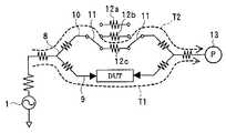
도 1은 본 발명의 바람직한 제1실시형태인 DUT의 반사 계수 측정장치를 나타낸다. 발진기로 이루어지는 신호원(1)이 발생한 측정 신호는 측정 신호 경로(2)를 통과하여 DUT에 인가된다. 측정 신호 경로(2)의 도중에는, 이 신호 경로(2)를 흐르는 신호의 일부를 분리하는 커플러(3)가 마련되어 있다. 커플러(3)에 의해 측정 신호 경로(2)와 결합된 오차 신호 경로(4)의 신호원측의 포트에는, 반사파를 스칼라값으로서 측정하는 파워 미터 등의 전력 측정기(5)가 접속되어 있으며, 오차 신호 경로(4)의 DUT측의 포트에는 방향성 전환 스위치(6)를 통하여 3종류의 방향성 오차(7a~7c)가 접속되어 있다. 방향성 오차(7a~7c)는 반사의 위상이 서로 다른 것으로서, 미리 그 방향성 오차의 관계값(상대적인 벡터값)을 구해 둔다.1 shows an apparatus for measuring reflection coefficients of a DUT according to a first preferred embodiment of the present invention. The measurement signal generated by the
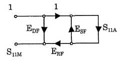
도 2는 반사 손실 측정의 오차 모델을 나타낸다. 여기서, S11A는 DUT의 반사 손실, SllM은 반사 손실의 측정값, EDF는 방향성 오차, ERF는 반사 주파수 응답 오차, ESF는 소스 매치 오차를 각각 나타낸다. 도 2의 오차 모델로부터, 피검체의 반사 손실(S11A)과 측정값(S11M)의 관계는 다음과 같이 된다.2 shows an error model of the return loss measurement. Here, S11A is the return loss of the DUT, SllM is the measurement of the reflection loss, EDF is the directional error, ERF is the reflection frequency response error, and ESF is the source match error. From the error model of FIG. 2, the relationship between the reflection loss S11A and the measured value S11M of the subject is as follows.

여기서, 많은 DUT에 있어서 측정해야 할 반사 손실(S11A)은 약 -15㏈~-20㏈정도이며, 또한 ESF는 프로브(probe)의 편입에 의해 -20㏈~-25㏈정도까지 작게 할 수 있다. 따라서, ESFS11A는 -35㏈~-45㏈로 측정 신호 레벨 O㏈에 비하여 매우 작은 값이 되므로, 다음 식과 같이 근사(近似)하여도 지장 없다.Here, the return loss (S11A ) to be measured for many DUTs is about -15 dB to -20 dB, and ESF can be reduced to -20 dB to -25 dB by incorporation of a probe. Can be. Therefore, ESF S11A is -35 kV to -45 kV, which is a very small value compared to the measured signal level O k, so it can be approximated by the following equation.

수학식 2 중의 ERF에 의한 오차에 대해서는, 미리 값 매겨진 DUT의 스칼라 측정값으로부터 보정 계수를 구함으로써 보정할 수 있는데, 방향성 오차(EDF)에 대해서는 통상의 스칼라 측정으로는 보정을 행할 수 없다. 그리하여, 본 발명에서는, 스칼라 측정이면서 방향성 오차(EDF)의 보정을 행하기 위해, 하기의 각 스텝을 실시 한다. 또한, 실제로는 S11M으로부터 EDF를 제거한 ΓT를 얻을 수 있다면, ΓT는 벡터 측정값으로 되어 있으므로, 통상의 오차 제거 순서를 밟음으로써, ERF와 ESF의 오차를 제거할 수 있다. 즉, 상기의 가정은 반드시 필요한 것은 아니며, ESFS11A를 무시할 수 없더라도, 본 발명을 적용할 수 있다.The error due to ERF in Equation (2) can be corrected by obtaining a correction coefficient from a scalar measurement value of a pre-valued DUT. However, a normal scalar measurement cannot be used to correct the directional error (EDF ). . Therefore, in the present invention, the following steps are performed to correct the directional error EDF while being a scalar measurement. In addition, if ΓT from which EDF is actually removed from S11M can be obtained, ΓT is a vector measurement value, so that the error of ERF and ESF can be eliminated by performing a normal error elimination procedure. In other words, the above assumption is not necessary, and the present invention can be applied even if ESF S11A cannot be ignored.
다음으로, DUT의 반사 계수 측정방법에 대하여 설명한다.Next, the reflection coefficient measuring method of the DUT will be described.
-방향성 오차의 값 매김-Value of Directional Error
3개의 방향성 오차(7a~7c)의 관계값(EDF1,EDF2,EDF3)을 구하기 위해, 예를 들면 교정이 끝난 VNA로 실측해도 되며, VNA로 측정을 행하지 않아도, 후술하는 바와 같은 독자적인 교정 순서에 의해 3개의 방향성 오차의 벡터 관계값을 얻을 수 있다. 예를 들면 2포트 VNA를 이용하여 3개의 방향성 오차의 관계값을 구하는 경우에는, VNA와 더불어 무반사 종단(終端)을 준비한다. 그리고, 도 1의 신호원측에 VNA의 포트(1)를, DUT측에 무반사 종단을, 전력 측정기측에 VNA의 포트(2)를 접속한다. 이 상태에서, 방향성 전환 스위치(6)를 3위치로 전환했을 때의 전달 계수의 3개의 측정값(S21)이 3개의 방향성 오차의 관계값이 된다. 이렇게 하여 값 매겨진 3개의 방향성 오차는 한번 측정장치를 제조하면 통상은 변화하지 않는 것이므로, 측정장치 제조시에 값 매김으로써, 이후 이 값을 계속하여 사용하는 것이 가능하며, 따라서 상기 측정장치를 사용하는 디바이스 양산 공정에서는, VNA가 불필요하다.In order to obtain the relation values EDF1 , EDF2 , and EDF3 of the three
-스칼라 측정-Scalar measurement
방향성 오차(7a~7c)의 값 매김을 종료한 후, 도 1에 나타내는 측정장치에 DUT를 접속하여 반사 측정을 행한다. 즉, 방향성 전환 스위치(6)를 전환했을 때의 3상태에 있어서의 반사파의 전력값(스칼라값)을 전력 측정기(5)에 의해 측정한다. 측정된 측정값은 도 1에 나타내는 DUT의 반사파(Rl)와 방향성 오차(7a~7c)의 반사파(R2)의 중첩 신호의 진폭이다.After completion of the measurement of the
-스칼라값으로부터 벡터값에의 변환-Conversion from scalar value to vector value
미리 값 매겨진 방향성 오차의 3개의 벡터값(EDF1,EDF2,EDF3)과, 상기 스칼라 측정에 의해 측정된 3개의 전력값(│Γm1│,│Γm2│,│Γm3│)을 이용하여, 1개의 벡터값 즉 DUT의 반사 계수(ΓT)로 변환한다. 그 변환식의 도출에 대하여, 이하에 설명한다.Three vector values (EDF1 , EDF2 , EDF3 ) of pre-valued directional error and three power values (│Γm1 │, │Γm2 │, │Γm3 │) measured by the scalar measurement are obtained. By using this method, it is converted into one vector value, that is, the reflection coefficient ΓT of the DUT. The derivation of the conversion equation will be described below.
벡터값의 실수부(實數部)와 허수부(虛數部)를 각각 첨자 x, y를 붙여서 나타내면, (EDF1,EDF2,EDF3) 및 ΓT는 이하와 같이 된다.When the real part and imaginary part of a vector value are represented by the subscripts x and y, (EDF1 , EDF2 , EDF3 ) and ΓT are as follows.
EDF1=(EDF1x,EDF1y)EDF1 = (EDF1x , EDF1y )
EDF2=(EDF2x,EDF2y)EDF2 = (EDF2x , EDF2y )
EDF3=(EDF3x,EDF3y)EDF3 = (EDF3x , EDF3y )
ΓT=(ΓTx,ΓTy)ΓT = (ΓTx , ΓTy )
각각 3개의 방향성 오차(EDF1,EDF2,EDF3)와, 3개의 DUT의 반사 계수 스칼라 측 정값(│Γm1│,│Γm2│,│Γm3│)과, 방향성 오차를 제거한 벡터 측정값(ΓT)의 관계식은 벡터 측정값(ΓT)이 취할 수 있는 값을 (x,y)로 하면, 벡터 측정값에 방향성 오차를 더한 점의 진폭이 반사 계수 스칼라 측정값이기 때문에, 수학식 3~수학식 5로 표현된다.Three directional errors (EDF1 , EDF2 , EDF3 ), reflection coefficient scalar measurements (│Γm1 │, │Γm2 │, │Γm3 │) of the three DUTs, and vector measurement without directional errors, respectively since the value of relation (ΓT) is a vector measured value (ΓT) a value that is taking (x, y) to when the amplitude reflection coefficient of a point on vector measurement plus the directional error scalar measure, mathematics It is expressed by


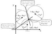
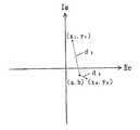
이하에, 수학식 3~5를 동시에 만족하는 벡터 측정값(ΓT)이 존재한다고 하는 가정을 근거로, 이 3개의 방정식을 만족하는 벡터 측정값(ΓT)을 도출한다. 통상의 방법으로 이 3개의 연립 방정식을 풀면, 4개의 해(解)가 얻어지고, 일치하는 2개의 해가 벡터 측정값(ΓT)이 된다. 그러나, 이 방법에서는 4개의 해를 얻기 위한 계산량이 방대하기 때문에, 계산기의 반올림 등으로 오차를 증대하기 쉽다. 그 때문에, 이하에 설명하는 기하학적인 방법을 이용하여 벡터 측정값(ΓT)을 도출하였다.In the following, based on the assumption that the vector measured value(T Γ) is present, which satisfies the following
수학식 3~5는 도 3에 나타내는 바와 같이 좌표(x-EDFx,y-EDFy)를 중심으로 하는 반경 │Γm│의 3개의 원으로 간주할 수 있다. 또한 "수학식 3~5를 동시에 만족하는 벡터 측정값(ΓT)이 존재한다"고 하는 가정으로부터, 이 3개의 원에 있어서의 공통의 교점이 존재하고, 그 교점이 벡터 측정값(ΓT)이 된다. 그러므로, 도 3에 나타내는 바와 같이 벡터 측정값(ΓT)은 각각 2개의 원의 교점을 통과하는 직선(예를 들면, 수학식 3, 4의 원의 교점을 통과하는 직선과, 수학식 3, 5의 원의 교점을 통과하는 직선)의 방정식을 2개 도출하여, 그 직선의 교점을 구함으로써 도출할 수 있다.
2개의 직선의 방정식을 이하에 나타낸다.The equation of two straight lines is shown below.
(수학식 3)-(수학식 4)로부터From (Equation 3)-(Equation 4)

(수학식 3)-(수학식 5)로부터From (Equation 3)-(Equation 5)

2개의 직선의 방정식인 수학식 6, 7로부터 교점의 좌표(ΓTx,ΓTy)를 도출하면, 수학식 8, 수학식 9가 된다.If the coordinates (ΓTx , ΓTy ) of the intersection are derived from the equations (6) and (7), which are two straight line equations, equations (8) and (9) are obtained.


이상으로부터, 3개의 DUT의 반사 계수 스칼라 측정값(│Γm1│,│Γm2│,│Γm3│)으로부터 방향성 오차를 제거한 벡터 측정값(ΓTx,ΓTy)을 도출할 수 있었다.From the above, the vector measurement values (ΓTx , ΓTy ) from which the directional errors were removed from the reflection coefficient scalar measurements (│Γm1 │, │Γm2 │, │Γm3 │) of the three DUTs were derived.
상기 설명에서는, DUT의 반사 계수(ΓTx,ΓTy)를 수학식을 이용하여 구한 예에 대하여 설명하였는데, 다음으로 스미스 차트를 이용하여 설명한다. 도 4는 값 매겨진 3개의 방향성 오차(7a~7c)의 관계값(EDF1,EDF2,EDF3)을 나타낸다. 도시하는 바와 같이, 3개의 벡터(EDF1,EDF2,EDF3)는 전력 측정기(6)의 측정 오차 이상으로 서로 떨어져 있는 것이 좋다. 여기서는, 값 매김시에 DUT측에 무반사 종단을 접속했기 때문에, 50Ω을 중점으로 하는 3개의 벡터로 나타나는데, 무반사 종단 이외의 것을 접속한 경우에는, 중점은 50Ω이 되지 않는다. 어떠한 경우이든, 3개의 방향성 오 차를 정량화하면 된다.In the above description, an example in which the reflection coefficients ΓTx and ΓTy of the DUT are obtained by using a mathematical equation has been described. Next, a Smith chart will be described. 4 shows the relation values EDF1 , EDF2 , and EDF3 of the three
도 5는 도 1에 나타내는 측정장치에 DUT를 접속하고, 방향성 전환 스위치(6)를 3위치로 전환했을 때의 전력 측정기(5)에 의한 측정값(스칼라값)을 나타낸 것이다. 측정값은 그 크기를 반경으로 하는 3개의 동심원(r=│S11M1│,r=│S11M2│,r=│S11M3│)으로 나타난다. 여기서, 도 4에서 구한 3개의 방향성 오차 벡터(EDF1,EDF2,EDF3)를 만족하면서, 도 5에서 얻어진 스칼라값을 만족하는 벡터(S11M1,S11M2,S11M3)의 조합을 구한다. 즉, 도 4에서 구한 3개의 방향성 오차 벡터의 정점을 연결하는 삼각형과 합동이면서, 그 정점이 3개의 동심원상에 위치하는 벡터의 조합을 구한다. 도 4의 삼각형을 도 5의 삼각형에 포개기 위한 벡터(S11A)가 DUT의 반사 계수이다.FIG. 5: shows the measured value (scalar value) by the
<바람직한 실시형태 2><
도 6은 본 발명의 바람직한 제2실시형태인 DUT의 전달 계수 측정장치를 나타낸다. 신호원(1)이 발생한 측정 신호는 파워 스플리터(power splitter)(8)에 의해 측정 신호 경로(9)와 오차 신호 경로(10)로 분기된다. 측정 신호 경로(9)에 들어간 한쪽의 측정 신호는 DUT에 인가되고, 오차 신호 경로(10)에 들어간 다른 쪽의 측정 신호는 누설 전환 스위치(11)를 통하여 3개의 누설 오차(12a~12c)의 어느 하나에 인가된다. DUT의 투과파와 누설 오차(12a~12c)의 투과파는 중첩되고, 중첩 신호는 전력 측정기(13)에 의해 전력값(스칼라값)으로서 측정된다. 누설 오차(12a~12c)는 투과파의 위상이 서로 다른 것으로, 미리 그 누설 오차의 관계값(상대적인 벡터값)을 구해 둔다.Fig. 6 shows a transfer coefficient measuring device of a DUT according to a second preferred embodiment of the present invention. The measurement signal generated by the
다음으로, DUT의 전달 계수 측정방법에 대하여 설명한다.Next, the transfer coefficient measuring method of the DUT will be described.
-누설 오차의 값 매김-Pricing of Leakage Errors
상술의 3개의 누설 오차(12a~12c)의 관계값(EXF1,EXF2,EXF3)을 구하기 위해, 예를 들면 교정이 끝난 VNA로 실측해도 되며, VNA로 측정하지 않아도, 후술하는 바와 같은 독자적인 교정 순서에 의해 누설 오차를 3종류로 변화시킨 각각의 상태의 누설 오차의 벡터값의 관계값을 얻을 수 있다. 예를 들면 2포트 VNA를 이용하여 3개의 누설 오차의 관계값을 구하는 경우에는, 도 6의 신호원측에 VNA의 포트(1)을, 전력 측정기측에 VNA의 포트(2)를 접속하여, 누설 전환 스위치(11)를 3위치로 전환했을 때의 전달 계수의 3개의 측정값(S21)이 3개의 누설 오차의 관계값이 된다. 또한, DUT를 접속하는 측정 단자간은 오픈 상태로 해도 되며, 각각에 무반사 종단을 접속해도 된다. 이렇게 하여 값 매긴 3개의 누설 오차의 관계값은 측정장치를 제조할 때에 한번 구해 두면, DUT의 측정시에는 이 값을 계속해서 사용할 수 있다.In order to find the relationship between the value (EXF1, EXF2, EXF3) of the three leakage errors (12a ~ 12c) in the above, for example, and may be measured by VNA calibration is completed, you do not need to measure a VNA, as described below The relationship value of the vector value of the leak error of each state which changed the leak error into three types by the original calibration procedure can be obtained. For example, when a relationship value of three leakage errors is obtained by using a two-port VNA, the
-스칼라 측정-Scalar measurement
누설 오차(12a~12c)의 값 매김을 종료한 후, 도 6에 나타내는 측정장치에 DUT를 접속하여 측정을 행한다. 즉, 누설 전환 스위치(11)를 전환했을 때의 3상태에 있어서의 투과파의 전력값(스칼라값)을 전력 측정기(13)에 의해 측정한다. 측정된 측정값은 도 6에 나타내는 DUT의 투과파(T1)와 누설 오차(12a~12c)의 투과 파(T2)의 중첩 신호의 진폭이다.After the value of the
-스칼라값으로부터 벡터값에의 변환-Conversion from scalar value to vector value
미리 값 매겨진 누설 오차의 3개의 벡터값과, 상기 스칼라 측정에 의해 측정된 3개의 전력값을 이용하여, DUT의 전달 계수(TT)로 변환한다. 전달 계수(TT)의 실수부와 허수부를 각각 첨자 x, y를 붙여서 (TTx,TTy)로 나타내면, 변환식은 이하의 수학식으로 표현된다.The three vector values of the leak error valued in advance and the three power values measured by the scalar measurement are converted into the transfer coefficient TT of the DUT. If the real part and the imaginary part of the transfer coefficient TT are denoted by (TTx , TTy ) with subscripts x and y, respectively, the conversion equation is expressed by the following equation.


여기서, │Tm1│,│Tm2│,│Tm3│은 누설 전환 스위치(11)를 3위치로 전환했을 때의 측정값(전력값)으로서, (EXF1x,EXF1y), (EXF2x,EXF2y), (EXF3x,EXF3y)는 3개의 누설 오차(12a~12c)의 관계값(EXF1,EXF2,EXF3)의 실수부와 허수부에 각각 첨자 x, y를 붙여서 나타낸 것이다.Tm1 , Tm2 , and Tm3 are measured values (power values) when the
이상의 계산을 행함으로써, 3개의 스칼라 측정값으로부터 1개의 벡터 측정값 이 얻어지게 되고, 이 값은 VNA가 통상 믹서에 의해 검출하는 벡터 측정값과 등가(等價)의 측정값이다. 이상과 같이 도출된 DUT의 벡터 측정값에 있어서의 측정계의 오차는 벡터 측정값이 얻어져 있기 때문에, VNA로 행해지는 통상의 교정의 순서를 밟음으로써 제거할 수 있다. 예를 들면 SOL 교정(Short, Open, Load의 교정 기준을 이용하는 교정방법)을 행함으로써, 측정값으로부터 측정계의 오차의 영향을 제거하여, DUT의 참값을 얻을 수 있다.By performing the above calculation, one vector measurement value is obtained from three scalar measurement values, and this value is a measurement value equivalent to the vector measurement value normally detected by a VNA by a mixer. The error of the measurement system in the vector measurement value of the DUT derived as described above can be eliminated by following the normal calibration procedure performed by the VNA because the vector measurement value is obtained. For example, by performing SOL calibration (a calibration method using calibration standards of short, open, and load), the true value of the DUT can be obtained by removing the influence of the error of the measurement system from the measured value.
<바람직한 실시형태 3><
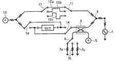
도 7은 도 1에 나타내는 반사 측정계와 도 6의 전달 측정계를 조합한 1패스 2포트 측정 시스템의 예를 나타낸다. 신호원(1)이 발생한 측정 신호는 파워 스플리터(8)에 의해 분기되고, 한쪽의 측정 신호는 DUT에 인가되며, 다른 쪽의 측정 신호는 누설 전환 스위치(11)를 통하여 3개의 누설 오차(12a~12c)의 어느 하나에 인가된다. DUT의 투과파와 누설 오차(12a~12c)의 투과파의 중첩 신호는 전력 측정기(13)에 의해 전력값(스칼라값)으로서 측정된다. DUT를 접속한 신호 경로(2)의 도중에는 커플러(3)가 마련되고, 커플러(3)에 의해 신호 경로(2)와 결합된 다른 신호 경로의 신호원측의 포트에는, 반사파의 전력값으로서 측정하는 전력 측정기(5)가 접속되며, DUT측의 포트에는 방향성 전환 스위치(6)를 통하여 3개의 방향성 오차(7a~7c)가 접속되어 있다. 방향성 전환 스위치(6)를 3위치로 전환하면서 전력 측정기(5)에 의해 전력값을 측정하고, 누설 전환 스위치(11)를 3위치로 전환하면서 전력 측정기(13)에 의해 전력값을 측정한다. 이들 측정값으로부터 수학식 8, 9 및 수학식 10, 11을 이용하여 DUT의 반사 계수(ΓT) 및 전달 계수(TT)를 구할 수 있다.FIG. 7 shows an example of a one-pass two-port measurement system in which the reflection measurement system shown in FIG. 1 and the transmission measurement system of FIG. 6 are combined. The measurement signal generated by the
<바람직한 실시형태 4><Preferred Embodiment 4>
도 8은 도 1에 나타내는 반사 측정계와 도 6의 전달 측정계를 조합한 풀 2포트 측정 시스템의 예를 나타낸다. 이 측정 시스템에서는, DUT의 양단에 접속되는 신호 경로에 전환 스위치(14)를 마련하여, 이들 스위치(14)에 의해 DUT의 방향을 변경할 수 있게 되어 있는 점을 제외하고, 그 밖의 구성은 도 7과 같기 때문에, 동일 부호를 부여하여 중복 설명을 생략한다. 이 실시형태에서는, 전환 스위치(14)의 전환에 의해 DUT의 방향을 바꾸어 측정할 수 있어, 풀 2포트의 측정이 가능해진다.FIG. 8 shows an example of a full two-port measurement system in which the reflection measurement system shown in FIG. 1 and the transmission measurement system of FIG. 6 are combined. In this measurement system, except that the
-실험예-Experimental Example
여기서, 반사 측정에 있어서의 본 발명의 실험예를 나타낸다. 여기서는, 스칼라 측정기로서 VNA 측정값의 진폭 정보만을 이용하여 스칼라 측정값으로 하기로 한다. 실제의 측정계에서는, 스칼라 측정기는 저렴한 파워 미터나 파워 센서를 이용하는 것이 일반적이지만, 본 실험예에서는 진폭 정보만으로부터 벡터 측정값이 얻어진다고 하는 본 발명의 특징을 증명하기 위해, 동일한 측정기를 이용한다. 즉, 같은 측정기를 이용하는 한 측정기의 측정값의 기계 오차(instrumental error) 등은 있을 수 없으며, 본 발명이 효과를 나타내면, 진폭 정보만으로부터 VNA의 측정값과 완전히 같은 측정값이 얻어질 것이므로, 이것으로 본 발명의 유효성을 증명하고자 하는 것이다.Here, the experimental example of this invention in reflection measurement is shown. Here, a scalar measurement value is used as a scalar measuring device using only amplitude information of the VNA measurement value. In an actual measuring system, a scalar measuring device generally uses an inexpensive power meter or a power sensor. However, in the present experimental example, the same measuring device is used to prove the feature of the present invention that a vector measurement value is obtained from only amplitude information. That is, there can be no instrumental error of the measured value of the measuring instrument as long as the same measuring instrument is used, and if the present invention is effective, the measured value exactly the same as the measured value of the VNA will be obtained from the amplitude information alone. It is intended to prove the validity of the present invention.
실험 조건을 이하에 나타낸다. 본 발명을 이용한 측정값과 비교하는 측정값 은 교정된 VNA의 측정값으로 한다.Experimental conditions are shown below. The measured value compared with the measured value using this invention is made into the measured value of the calibrated VNA.
피검체: 동축(同軸) 커넥터 접속의 CPW 전송로에 표면 실장 디바이스를 접속한 것Subject: A surface mount device connected to a CPW transmission line with a coaxial connector
벡터 측정기: E8364B(Agilent Technologies)Vector Meter: A83ent Technologies (E8364B)
스칼라 측정기: E8364B(Agilent Technologies)(측정값의 진폭 정보만)Scalar Meter: Agilent Technologies (E8364B) (only amplitude information of measured values)
주파수 범위: 34㎓~42㎓Frequency Range: 34㎓ ~ 42㎓
데이터수: 801점Number of data: 801 points
IF 대역폭: 100㎐(평균화 처리 없음)IF bandwidth: 100 Hz (no averaging)
커플러: Ka 밴드(26.5㎓~40㎓) 도파관(導波管) 10㏈ 커플러Coupler: Ka band (26.5 ㎓ to 40 ㎓) waveguide 10 ㏈ coupler
방향성 오차: 3개의 오프셋 쇼트(offset short)(λg=0, 1/6, 1/3@38㎓)Directional error: 3 offset shorts (λg = 0, 1/6, 1/3 @ 38㎓)
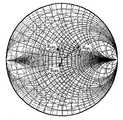
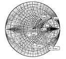
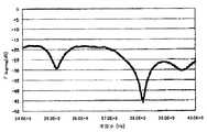
도 9에 벡터 측정기로 측정한 38㎓에 있어서의 3개의 방향성 오차의 관계값(EDFl,EDF2,EDF3)을 나타낸다. 도 10에 방향성 오차가 다른 3개의 경우에 있어서의 DUT 스칼라 측정값을 나타낸다. 도 11, 도 12는 도 9, 도 10의 측정값을 수학식 8, 수학식 9에 대입하여 계산한 후의 DUT의 측정값(진폭)과 벡터 측정값을 나타낸다. 도 12에서는 3개의 스칼라 측정값으로부터 위상 정보를 포함한 벡터 측정값이 얻어져 있는 것이 나타나 있다.Fig. 9 shows relationship values EDF1 , EDF2 , and EDF3 of three directional errors at 38 kHz measured by a vector measuring instrument. 10 shows the DUT scalar measurement values in three cases in which the directional errors are different. 11 and 12 show measured values (amplitudes) and vector measured values of the DUT after substituting the measured values shown in FIGS. 9 and 10 into equations (8) and (9). 12 shows that the vector measured value including the phase information is obtained from the three scalar measured values.
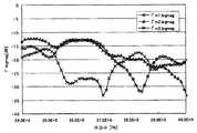
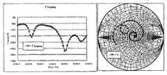
도 11, 도 12의 측정값은 측정계의 오차도 포함하고 있다. 그 때문에, 벡터 오차 보정을 행하기 위해 마찬가지로 본 발명의 측정계를 이용하여 표준기의 측정을 행하고, 도 11, 도 12의 측정값을 보정하여 DUT의 벡터 측정값(ΓD)을 산출하였 다. 도 13, 도 14에 본 발명방법에 의한 DUT의 측정값(ΓD)과 교정된 VNA를 이용한 DUT의 측정값(ΓA)을 비교한 그래프를 나타낸다. 도 13, 도 14로부터 명백하듯이, 양쪽의 측정값은 대부분 일치하고 있어, 본 발명이 정확한 벡터 측정방법인 것을 알 수 있다.The measured values of FIG. 11 and FIG. 12 also contain the error of a measurement system. Therefore, in order to perform the vector error correction, a standard instrument was measured using the measuring system of the present invention, and the measured values of FIGS. 11 and 12 were corrected to calculate the vector measured value ΓD of the DUT. 13 and 14 show graphs comparing the measured value ΓD of the DUT according to the present invention with the measured value ΓA of the DUT using the calibrated VNA. As apparent from Fig. 13 and Fig. 14, both measurement values are mostly in agreement, and it can be seen that the present invention is an accurate vector measurement method.
<바람직한 실시형태 5><
-스칼라 측정기에 의해 3개의 방향성 오차의 관계값을 구하는 방법-How to find the relationship value of three directional errors by scalar meter
여기서, VNA를 이용하지 않고 스칼라 측정기에 의해 3개의 방향성 오차의 관계값을 구하는 방법에 대하여 설명한다. 우선, 각각 다른 반사 계수를 가지는 2종류의 DUT(각각 m, n)를 도 1에 나타내는 측정장치에 접속하여, 각각 3개의 방향성 오차의 상태에 있어서 측정한다. 본 순서에서는, 3개의 방향성 오차의 상호 관계를 알면 충분하고, 위상이나 절대 위치는 문제가 되지 않으므로, 간단하기 때문에, 가령 1개째의 DUT(m)의 1개째의 방향성 오차 상태에 있어서의 측정값은 위상이 0°라고 하자. 이 때의 복소 평면상에서의 위치는 도 15의 Γm1과 같이 된다. 이에 대하여, 2개째 및 3개째의 방향성 오차 상태에 있어서의 측정값의 복소 평면상에서의 위치는 예를 들면 도 15의 Γm2, Γm3과 같이 된다. 여기서, 관측값은 스칼라값이므로, 이들 점의 실제의 위치는 모르며, 단지 중심이 원점이며 반경이 │Γm2│, │Γm3│인 원주상의 어딘가에 이들 점이 존재할 것이라는 것만을 알고 있는 것에 불과하다. 그리하여, 가령 Γm1로부터 이들 점에의 각도가 θ1, θ2라고 하자. 당연히, θ1, θ2는 이 시점에서는 미지량(未知量)이다.Here, a method of obtaining the relationship value of three directional errors by a scalar measuring instrument without using a VNA will be described. First, two types of DUTs (m and n, respectively) each having different reflection coefficients are connected to the measuring apparatus shown in Fig. 1 and measured in the state of three directional errors respectively. In this procedure, it is sufficient to know the mutual relationship between the three directional errors, and since the phase and the absolute position are not a problem, it is simple, and therefore, the measured value in the first directional error state of the first DUT (m), for example. Let silver phase be 0 °. The position on the complex plane at this time is as shown by Γm1 in FIG. 15. In contrast, the position on the complex plane of the measured value in the second and third directional error states is, for example, Γm2 and Γm3 in FIG. 15. Here, since the observations are scalar values, we do not know the actual position of these points, but we only know that they will exist somewhere on the circumference whose center is the origin and the radius is | Γm2 |, | Γm3 | . Thus, for example, assume that the angles from Γm1 to these points are θ1 , θ2 . Naturally, θ1 and θ2 are unknown at this point.
다음으로, 2개째의 DUT(n)의 1개째의 방향성 오차 상태에 있어서의 측정값(Γn1)이 Γm1에 대하여 위상이 Φ만큼 벗어나 있다고 하면, 도 15와 같이 된다. 또한, Γn1에 대하여, Γn2, Γn3은, 방향성 오차의 상호 관계는 앞의 경우와 같기 때문에 각도는 θ1, θ2일 것이며, 동시에 각각은 중심이 원점이며 반경이 │Γn2│, │Γn3│인 원주(파선으로 나타냄)상에 있을 것이기 때문에, 도 15와 같이 각각의 위치가 결정된다.Next, suppose that the measured value Γn1 in the first directional error state of the second DUT (n) is out of phase by Φ relative to Γm1 , as shown in FIG. 15. In addition, for Γn1 , Γn2 and Γn3 have angles of θ1 and θ2 since the correlation between the directional errors is the same as in the previous case, and at the same time, the center is the origin and the radius is │Γn2 │, Since it will be on the circumference (indicated by the broken line) which is | Γn3 |, each position is determined as shown in FIG.
그런데, 가령 θ1, θ2, Φ가 올바르게 선택되어 있으면, 방향성 오차는 DUT에 따르지 않고 일정한 이상, Γm1~Γm3이 만드는 삼각형과 Γn1~Γn3이 만드는 삼각형은 합동이 된다. 그리하여, 이들 삼각형이 합동이 되도록(실제로는 측정 오차 등의 영향이 있기 때문에 가장 합동에 가까워 지도록) θ1, θ2, Φ를 선택함으로써, 3개의 방향성 오차의 관계값이 구해진다.By the way, if θ1 , θ2 and Φ are correctly selected, the directional error does not depend on the DUT, and the triangle made by Γm1 to Γm3 and the triangle made by Γn1 to Γn3 become congruent. Thus, by selecting θ1 , θ2 , and Φ so that these triangles become congruent (actually closest to the congruence because there is an influence of measurement error or the like), the relation values of three directional errors are obtained.
보다 구체적으로는, 다음과 같이 된다.More specifically, it becomes as follows.
(x0,y0)을 통과하고, 기울기가 θ인 직선은 다음 식으로 부여된다.A straight line passing through (x0 , y0 ) and having a slope of θ is given by the following equation.
sinθ(x-x0)-cosθ(y-y0)=0sinθ (xx0 ) -cosθ (yy0 ) = 0
중심이 원점이며 반경이 r인 원은 다음 식으로 부여된다.The circle whose center is the origin and the radius r is given by
x2+y2=r2x2 + y2 = r2
상기 직선과 원의 교점(x,y)은 다음과 같다.The intersection point (x, y) of the straight line and the circle is as follows.
x=x0sin2θ-y0cosθsinθ±cosθ√{r2-(x0sinθ-y0cosθ)2}x = x0 sin2 θ-y0 cosθsinθ ± cosθ√ {r2- (x0 sinθ-y0 cosθ)2 }
y=y0cos2θ-x0cosθsinθ±sinθ√{r2-(x0sinθ-y0cosθ)2}y = y0 cos2 θ-x0 cosθsinθ ± sinθ√ {r2- (x0 sinθ-y0 cosθ)2 }
우선, θ1, θ2, Φ에 적당한 값을 가정한다.First, assume values appropriate for θ1 , θ2 , and Φ.
Γm1의 좌표는 (│Γm1│,0)으로 부여된다.The coordinate of Γm1 is given by (│Γm1 │, 0).
Γm2의 좌표는 (x0,y0)을 Γm1의 좌표로 하고, 반경(r)을 │Γm2│로 하고, 기울기(θ)를 θ1로 하여 구할 수 있다.The coordinate of Γm2 can be obtained by (x0 , y0 ) as the coordinate of Γm1 , the radius r as │Γm2 │, and the inclination θ as θ1 .
Γm3의 좌표는 Γm2와 동일하게 구할 수 있다.The coordinate of Γm3 can be obtained in the same manner as Γm2 .
Γn1의 좌표는 (│Γn1│cosΦ,│Γn1│sinΦ)로 부여된다.The coordinate of Γn1 is given by (│Γn1 │cosΦ, │Γn1 │sinΦ).
Γn2의 좌표는 Γm2와 동일하게 구할 수 있다.The coordinate of Γn2 can be obtained in the same manner as Γm2 .
Γn3의 좌표는 Γm3과 동일하게 구할 수 있다.The coordinate of Γn3 can be obtained in the same manner as Γm3 .
이상 얻어진 좌표로부터, 이하의 식에 의해 추정 오차(E)를 구한다.From the coordinates obtained above, the estimation error E is calculated | required by the following formula.
E=│Γn1-Γm1│2+│Γn2-Γm2│2E = │Γn1 -Γm1 │2 + │Γn2 -Γm2 │2
적당한 최적화 알고리즘에 의해 θ1, θ2, Φ를 변화시켜, 상기 E가 최소가 되는 θ1, θ2, Φ를 구한다. 이렇게 하여 얻어진 θ1, θ2, Φ에 대한 Γm1, Γm2, Γm3을 3개의 방향성 오차의 관계값으로 하면 된다. 또한, 3개의 방향성 오차의 관계값을 얻은 후에, 통상의 1포트 교정을 행하는 것이 필요하다.By means of a suitable optimizing algorithm, θ1, θ2, by changing the Φ, the obtained θ1, θ2, Φ is the E is minimized. What is necessary is just to make Γm1 , Γm2 , and Γm3 with respect to θ1 , θ2 , and Φ thus obtained as relation values of three directional errors. Moreover, after obtaining the relationship value of three directional errors, it is necessary to perform normal 1-port calibration.
이상과 같이 VNA를 사용하지 않고, 스칼라 측정기만으로 3개의 방향성 오차의 관계값을 얻을 수 있으므로, 어떠한 원인으로 측정장치의 상태가 변한 경우 등에도, VNA를 사용하지 않고 다시 올바른 3개의 방향성 오차의 관계값을 얻을 수 있다. 즉, 본 발명에 따른 측정장치를 사용하는 양산 공정 자체에서 측정장치의 교정을 행할 수 있기 때문에, 이상 발생시의 복구 등이 용이해진다. 또한, 원래부터 VNA가 불필요하므로, VNA를 소유하고 있지 않은 경우에도 벡터 측정을 실시할 수 있다. 더불어, VNA가 대응하고 있지 않은 고주파 영역에서도 벡터 측정을 실현할 수 있는 이점도 있다.As described above, since three directional errors can be obtained using only a scalar measuring instrument without using a VNA, even if the state of the measuring device is changed due to any reason, the three directional errors are correct again without using the VNA. You can get the value. That is, since the measuring apparatus can be calibrated in the mass production process itself using the measuring apparatus according to the present invention, recovery in case of abnormality is facilitated. In addition, since no VNA is originally required, vector measurement can be performed even when the VNA is not owned. In addition, there is an advantage in that vector measurement can be realized even in a high frequency region that the VNA does not support.
<바람직한 실시형태 6><
도 16은 중첩되는 벡터 신호가 2개인 경우의 반사 측정계를 나타낸다. 도 1과 동일 부분에는 동일 부호를 부여하여 중복 설명을 생략한다.Fig. 16 shows a reflection measuring system in the case of two overlapping vector signals. The same reference numerals are given to the same parts as in FIG. 1 to omit duplicate explanation.
이 실시형태의 경우, 중첩 신호인 방향성 오차 성분이 2개밖에 없기 때문에, 기본적으로는 벡터값이 2개 도출되므로, DUT의 반사 신호의 벡터값을 하나로 구할 수 없다. 그러나, 양산에 있어서의 선별 등에서는, 설계시 및 개발시의 DUT의 특성으로부터 추정하여 옳다고 생각되는 쪽을 선택함으로써, DUT의 반사 신호의 벡터값을 구하는 것이 가능하다.In this embodiment, since there are only two directional error components that are overlapping signals, two vector values are basically derived, so that the vector values of the reflected signals of the DUT cannot be obtained as one. However, in screening in mass production and the like, it is possible to obtain a vector value of the reflected signal of the DUT by estimating from the characteristics of the DUT during design and development and selecting the one that is considered to be correct.
도 16과 같은 반사 측정계의 경우, 2개의 방법성 오차(EDF1,EDF2)를 전환하여, 스칼라 측정기에 의해 측정된 DUT의 2개의 전력값(│Γm1│,│Γm2│)은 수학식 3 및 수학식 4와 같이 된다. 이들 전력값으로부터, 방향성 오차를 제거한 DUT의 반사 신호의 벡터값은 수학식 12~14에 나타내는 바와 같이, (x1,y1), (x2,y2)의 2개가 도출된다.In the case of the reflection measuring system as shown in FIG. 16, two methodological errors (EDF1 and EDF2 ) are switched so that two power values (│Γm1 │, │Γm2 │) of the DUT measured by the scalar meter are


이 경우, 각 주파수점에 있어서, 도 17에 나타내는 바와 같이 스미스 차트상에는 (x1,y1), (x2,y2)의 2개의 벡터 측정값이 플롯되게 된다. 양산에 있어서는, 거의 같은 특성을 가지는 피검체의 측정을 행하는 것이 통례이다. 그때, 피검체의 특성이 기지이면(시뮬레이션값이어도 됨), 이번 측정계를 이용해도, 피검체의 2개의 벡터값으로부터 피검체와 동종의 기지 특성에 가까운 것을 선택함으로써, 피검체의 특성을 추정할 수 있다.In this case, at each frequency point, two vector measurement values (x1 , y1 ) and (x2 , y2 ) are plotted on the Smith chart as shown in FIG. 17. In mass production, it is customary to measure a subject having almost the same characteristics. In that case, if the characteristic of the subject is known (may be a simulated value), even if this measurement system is used, the characteristic of the subject can be estimated by selecting one close to the known characteristic of the subject and the same from the two vector values of the subject. Can be.
벡터값의 선택방법에 대하여, 이하에 설명한다.A method of selecting a vector value will be described below.
도 17에 있어서, 측정한 피검체와 같은 특성을 가지며, 어떠한 방법으로 값이 기지인 피검체의 특성(a,b)을 플롯한다. 이 예에서는 명백하게 (x2,y2) 쪽이 기지 특성(a,b)에 가깝기 때문에, (x2,y2)의 값이 올바르다고 추정할 수 있지만, 실제로는 이하와 같은 비교 처리를 행하는 것이 좋다. 즉, (a,b)에 대한 (x1,y1)의 거리(d1)와 (x2,y2)의 거리(d2)는 다음 식으로 표현된다.In FIG. 17, the characteristic (a, b) of the subject which has the same characteristic as the measured subject and whose value is known is plotted in some way. In this example, since (x2 , y2 ) is close to the known characteristic (a, b), it can be estimated that the value of (x2 , y2 ) is correct. It is good. That is, the distance (d2) of the distance (d1) and (x2, y2) of the (x1, y1) to (a, b) is represented by the following formula:


d1과 d2를 비교하여, 값이 작은 쪽의 벡터값, 즉 (a,b)에 가까운 쪽이 올바른 측정값이라고 추정할 수 있다.By comparing d1 and d2 , one can assume that the smaller the value, the closer to (a, b), is the correct measurement.
다음으로, 수학식 12~14를 이용하여 실제로 벡터값의 도출을 행한 실험 결과를 나타낸다. 실험 조건은 이하와 같으며, 방향성 오차로서 2개의 오프셋 쇼트를 이용하였다.Next, the experimental results of actually deriving the vector value using the equations (12) to (14) are shown. Experimental conditions were as follows and two offset shots were used as directional errors.
피검체 시료: 동축 커넥터 접속의 CPW 전송로에 표면 실장 디바이스를 접속한 것Sample under test: Surface-mounted device connected to CPW transmission line with coaxial connector
벡터 측정기: E8364B(Agilent Technologies)Vector Meter: A83ent Technologies (E8364B)
스칼라 측정기: E8364B(Agilent Technologies)(측정값의 진폭 정보만)Scalar Meter: Agilent Technologies (E8364B) (only amplitude information of measured values)
주파수 범위: 34㎓~42㎓Frequency Range: 34㎓ ~ 42㎓
데이터수: 801점Number of data: 801 points
IF 대역폭: 100㎐(평균화 처리 없음)IF bandwidth: 100 Hz (no averaging)
커플러: Ka 밴드(26.5㎓~40㎓) 도파관 10㏈ 커플러Coupler: Ka band (26.5㎓ ~ 40㎓) waveguide 10㏈ coupler
방향성 오차: 2개의 오프셋 쇼트(λg=0, 1/6@38㎓)Directional error: 2 offset shorts (λg = 0, 1/6 @ 38㎓)
수학식 12, 14 및 수학식 13, 14를 이용하여 피검체 시료의 진폭 및 벡터값을 도출한 결과를 각각 도 18 및 도 19에 나타낸다. 도 20은 미리 구해진 기지의 동종류의 피검체 시료의 특성이다. 도 18, 도 19 중 도 20에 가까운 값을 선택하면, 그것이 측정한 피검체 시료의 벡터값이라고 추정할 수 있다. 이번에는 도 20에 가까운 값은 모두 도 18의 값, 즉 수학식 12, 14를 이용하여 도출한 값으로 되어 있기 때문에, 도 18이 피험체 시료의 진폭 및 벡터값이라고 추정할 수 있다.18 and 19 show the results of deriving the amplitude and the vector value of the subject
상기 설명에서는, 2개의 방향성 오차를 전환하여 DUT의 반사 계수를 측정하는 예에 대하여 설명하였는데, 2개의 누설 오차를 전환하여 DUT의 전달 계수를 측정하는 것도 가능하다. 그 경우에는, 예를 들면 도 6에 있어서의 3개의 누설 오차(12a~12c) 중의 2개를 이용하면 된다.In the above description, an example of measuring the reflection coefficient of the DUT by switching two directional errors is described, but it is also possible to measure the transfer coefficient of the DUT by switching two leakage errors. In that case, two of three
종래의 VNA의 구성을 이용하여 반사파 및 투과파의 벡터 측정을 하는 경우, 주파수가 높아짐으로써 측정 시스템의 가격이 현저하게 상승함과 동시에 고정밀도 측정이 곤란해지는데, 본 발명에 의하면, 거의 주파수에 의존하지 않는 기본적이면서 저렴한 측정인 전력 측정에 의해 벡터 측정을 실시할 수 있다. 즉, 3개의 스칼라 측정값만을 이용하여 반사파 및 투과파의 벡터 측정이 가능하므로, 주파수가 높아져도 전력 측정이 가능한 한, 측정기 가격의 상승을 억제하면서, 고정밀도 측정을 실현하는 벡터 오차 보정이 가능해진다고 하는 효과가 얻어진다. 따라서, 종래의 VNA가 고가이기 때문에 특성 선별 공정의 비용이 증대하는 밀리파대 이상의 고주파 상품에 있어서, 본 발명을 이용한 고정밀도이면서 저렴한 측정기로 바꿈으로써, 벡터 측정에 관한 대폭의 비용 절감을 기대할 수 있다. 또한, 다품종·소량생산의 품종이 많은 밀리파대 이상의 고주파 상품에 있어서는, 본 발명에 의한 저렴한 측정기라면 상품마다 이것을 구비하는 것이 가능해지므로, 공정의 순서 바꿈 등의 공정의 부담을 적게 할 수 있다. 측정계의 미묘한 조정이 요구되는 밀리파대 이상의 측정 공정에 있어서는, 상기 특징은 상품 측정의 정밀도·신뢰성을 확보하는 효과가 크다.In the case of vector measurement of reflected and transmitted waves using the conventional VNA configuration, the higher the frequency, the higher the cost of the measurement system and the higher the accuracy, the more difficult the measurement. Vector measurements can be performed by power measurements, which are basic and inexpensive measurements that do not depend. In other words, vector measurement of reflected and transmitted waves is possible using only three scalar measurements, and as long as the power can be measured even at high frequencies, vector error correction is possible while realizing high-precision measurement while suppressing the increase in the price of the measuring instrument. The effect to lose is obtained. Therefore, in the high frequency products of the millimeter wave or more where the cost of the characteristic selection process increases because the conventional VNA is expensive, a significant cost reduction for vector measurement can be expected by changing to a high precision and inexpensive measuring instrument using the present invention. . Moreover, in the high frequency product of the millimeter wave or more with many varieties of small variety and small quantity production, if it is an inexpensive measuring instrument by this invention, it becomes possible to provide this for every product, and can reduce the burden of processes, such as order change of a process. In the measurement process of the millimeter wave or more where delicate adjustment of the measurement system is required, the above characteristics have a great effect of ensuring accuracy and reliability of product measurement.
Claims (10)
Translated fromKoreanApplications Claiming Priority (2)
| Application Number | Priority Date | Filing Date | Title |
|---|---|---|---|
| JPJP-P-2005-00253158 | 2005-09-01 | ||
| JP2005253158 | 2005-09-01 |
Publications (2)
| Publication Number | Publication Date |
|---|---|
| KR20080032223A KR20080032223A (en) | 2008-04-14 |
| KR100956503B1true KR100956503B1 (en) | 2010-05-07 |
Family
ID=37835619
Family Applications (1)
| Application Number | Title | Priority Date | Filing Date |
|---|---|---|---|
| KR1020087004315AActiveKR100956503B1 (en) | 2005-09-01 | 2006-08-23 | Method and device for measuring scattering coefficient of subject |
Country Status (6)
| Country | Link |
|---|---|
| US (1) | US7592818B2 (en) |
| EP (1) | EP1939637A4 (en) |
| JP (1) | JP4941304B2 (en) |
| KR (1) | KR100956503B1 (en) |
| CN (1) | CN101258412B (en) |
| WO (1) | WO2007029495A1 (en) |
Families Citing this family (11)
| Publication number | Priority date | Publication date | Assignee | Title |
|---|---|---|---|---|
| US7545150B2 (en)* | 2007-02-28 | 2009-06-09 | Agilent Technologies, Inc. | Differential vector network analyzer |
| US7671605B2 (en)* | 2008-01-17 | 2010-03-02 | Agilent Technologies, Inc. | Large signal scattering functions from orthogonal phase measurements |
| KR101152046B1 (en)* | 2008-02-05 | 2012-07-03 | 가부시키가이샤 무라타 세이사쿠쇼 | Measurement error correcting method and electronic part characteristic measuring instrument |
| WO2010069344A1 (en)* | 2008-12-17 | 2010-06-24 | Verigy (Singapore) Pte. Ltd. | Method and apparatus for determining relevance values for a detection of a fault on a chip and for determining a fault probability of a location on a chip |
| GB201219310D0 (en)* | 2012-10-26 | 2012-12-12 | Mesuro Ltd | Calibration of high frequency signal measurement systems |
| WO2018109782A1 (en)* | 2016-12-13 | 2018-06-21 | Indian Institute Of Technology Bombay | Network analyzer for measuring s-parameters of rf device |
| JP7153309B2 (en)* | 2018-06-04 | 2022-10-14 | 国立研究開発法人産業技術総合研究所 | Measurement method of reflection coefficient using vector network analyzer |
| US11054450B2 (en)* | 2019-07-17 | 2021-07-06 | Rohde & Schwarz Gmbh & Co. Kg | Method of calibrating a measurement and analyzing device as well as method of measuring a frequency-converting device under test |
| US11474137B2 (en)* | 2020-09-18 | 2022-10-18 | Rohde & Schwarz Gmbh & Co. Kg | Test system |
| CN114280156B (en)* | 2021-12-28 | 2022-10-21 | 杭州电子科技大学 | Sub-surface crack length and depth measuring method based on laser ultrasound |
| CN115219815B (en)* | 2022-06-27 | 2025-04-15 | 中国电子科技集团公司第十三研究所 | A waveguide port S parameter calibration method and device based on the center of an inscribed circle |
Citations (4)
| Publication number | Priority date | Publication date | Assignee | Title |
|---|---|---|---|---|
| US5498551A (en) | 1985-12-23 | 1996-03-12 | Janssen Pharmaceutica N.V. | Method for the detection of specific binding agents and their corresponding bindable substances |
| US5948624A (en) | 1994-05-11 | 1999-09-07 | Rothschild; Kenneth J. | Methods for the detection and isolation of biomolecules |
| US6576460B1 (en) | 1999-10-28 | 2003-06-10 | Cornell Research Foundation, Inc. | Filtration-detection device and method of use |
| JP2004198415A (en) | 2002-12-16 | 2004-07-15 | Agilent Technol Inc | Distortion measurement with vector network analyzer |
Family Cites Families (9)
| Publication number | Priority date | Publication date | Assignee | Title |
|---|---|---|---|---|
| US4521728A (en)* | 1982-08-23 | 1985-06-04 | Renato Bosisio | Method and a six port network for use in determining complex reflection coefficients of microwave networks |
| GB8524825D0 (en) | 1985-10-08 | 1985-11-13 | Secr Defence | Rf interferometer |
| GB2196745B (en)* | 1986-10-21 | 1990-05-16 | Marconi Instruments Ltd | Test arrangement |
| CN1004173B (en)* | 1987-12-07 | 1989-05-10 | 浙江大学 | Method and system for testing complex permittivity and complex permeability of microwave absorbing materials |
| US5434511A (en)* | 1993-05-24 | 1995-07-18 | Atn Microwave, Inc. | Electronic microwave calibration device |
| US5467021A (en)* | 1993-05-24 | 1995-11-14 | Atn Microwave, Inc. | Calibration method and apparatus |
| FR2817620B1 (en)* | 2000-12-04 | 2003-02-07 | Centre Nat Rech Scient | ELECTROMAGNETIC CHARACTERIZATION DEVICE OF A STRUCTURE UNDER TEST |
| JP3540797B2 (en)* | 2002-01-18 | 2004-07-07 | 利幸 矢加部 | Seven-port correlator, calibration method thereof, and vector network analyzer using seven-port correlator |
| US6838885B2 (en)* | 2003-03-05 | 2005-01-04 | Murata Manufacturing Co., Ltd. | Method of correcting measurement error and electronic component characteristic measurement apparatus |
- 2006
- 2006-08-23JPJP2007534315Apatent/JP4941304B2/enactiveActive
- 2006-08-23CNCN2006800310641Apatent/CN101258412B/enactiveActive
- 2006-08-23WOPCT/JP2006/316465patent/WO2007029495A1/enactiveApplication Filing
- 2006-08-23EPEP06782918Apatent/EP1939637A4/ennot_activeCeased
- 2006-08-23KRKR1020087004315Apatent/KR100956503B1/enactiveActive
- 2008
- 2008-02-29USUS12/039,892patent/US7592818B2/enactiveActive
Patent Citations (4)
| Publication number | Priority date | Publication date | Assignee | Title |
|---|---|---|---|---|
| US5498551A (en) | 1985-12-23 | 1996-03-12 | Janssen Pharmaceutica N.V. | Method for the detection of specific binding agents and their corresponding bindable substances |
| US5948624A (en) | 1994-05-11 | 1999-09-07 | Rothschild; Kenneth J. | Methods for the detection and isolation of biomolecules |
| US6576460B1 (en) | 1999-10-28 | 2003-06-10 | Cornell Research Foundation, Inc. | Filtration-detection device and method of use |
| JP2004198415A (en) | 2002-12-16 | 2004-07-15 | Agilent Technol Inc | Distortion measurement with vector network analyzer |
Also Published As
| Publication number | Publication date |
|---|---|
| KR20080032223A (en) | 2008-04-14 |
| JPWO2007029495A1 (en) | 2009-03-19 |
| EP1939637A4 (en) | 2011-02-23 |
| CN101258412B (en) | 2013-02-20 |
| EP1939637A1 (en) | 2008-07-02 |
| US20080211515A1 (en) | 2008-09-04 |
| JP4941304B2 (en) | 2012-05-30 |
| WO2007029495A1 (en) | 2007-03-15 |
| US7592818B2 (en) | 2009-09-22 |
| CN101258412A (en) | 2008-09-03 |
Similar Documents
| Publication | Publication Date | Title |
|---|---|---|
| KR100956503B1 (en) | Method and device for measuring scattering coefficient of subject | |
| US6853198B2 (en) | Method and apparatus for performing multiport through-reflect-line calibration and measurement | |
| US9921287B2 (en) | Method for calibrating a test rig | |
| US7068049B2 (en) | Method and apparatus for measuring a device under test using an improved through-reflect-line measurement calibration | |
| CN103399286B (en) | A kind of measurement calibration steps of many characteristic impedance network | |
| JP6474720B2 (en) | Method for determining the scattering parameters of the electronic device under test | |
| US6650123B2 (en) | Methods for determining characteristics of interface devices used with vector network analyzers | |
| US10042029B2 (en) | Calibration of test instrument over extended operating range | |
| US20100204943A1 (en) | Method and device for the calibration of network analyzers using a comb generator | |
| US8126670B2 (en) | Method and device for calibrating a network analyzer for measuring at differential connections | |
| US20050156585A1 (en) | Reduced complexity transmission line and waveguide fault tester | |
| RU2524049C1 (en) | Device for measuring absolute complex transmission and reflection coefficients of microwave devices with frequency conversion | |
| JP2004301839A (en) | Calibration method for performing multiport measurements on semiconductor wafers | |
| US5440236A (en) | Calibrating a network analyzer by making multiple measurements on a common transmission line with a movable discontinuity | |
| US5734268A (en) | Calibration and measurment technique and apparatus for same | |
| US7768271B2 (en) | Method for calibration of a vectorial network analyzer having more than two ports | |
| US7030625B1 (en) | Method and apparatus for performing a minimum connection multiport through-reflect-line calibration and measurement | |
| US7769555B2 (en) | Method for calibration of a vectorial network analyzer | |
| Hodgetts et al. | A unified treatment of the theory of six-port reflectometer calibration using the minimum of standards | |
| Schramm et al. | A SOLR calibration procedure for the 16-term error model | |
| Heuermann | Calibration of a network analyzer without a thru connection for nonlinear and multiport measurements | |
| RU2753828C1 (en) | Method for calibration and determination of inherent systematic errors of vector network analyser | |
| JP4149428B2 (en) | Vector network analyzer and calibration method thereof | |
| JPS62190471A (en) | Test apparatus | |
| Torok et al. | Efficient broadband method for equivalent source reflection coefficient measurements |
Legal Events
| Date | Code | Title | Description |
|---|---|---|---|
| A201 | Request for examination | ||
| PA0105 | International application | Patent event date:20080222 Patent event code:PA01051R01D Comment text:International Patent Application | |
| PA0201 | Request for examination | ||
| PG1501 | Laying open of application | ||
| E902 | Notification of reason for refusal | ||
| PE0902 | Notice of grounds for rejection | Comment text:Notification of reason for refusal Patent event date:20091030 Patent event code:PE09021S01D | |
| E701 | Decision to grant or registration of patent right | ||
| PE0701 | Decision of registration | Patent event code:PE07011S01D Comment text:Decision to Grant Registration Patent event date:20100426 | |
| GRNT | Written decision to grant | ||
| PR0701 | Registration of establishment | Comment text:Registration of Establishment Patent event date:20100428 Patent event code:PR07011E01D | |
| PR1002 | Payment of registration fee | Payment date:20100428 End annual number:3 Start annual number:1 | |
| PG1601 | Publication of registration | ||
| FPAY | Annual fee payment | ||
| PR1001 | Payment of annual fee | Payment date:20130328 Start annual number:4 End annual number:4 | |
| PR1001 | Payment of annual fee | Payment date:20140401 Start annual number:5 End annual number:5 | |
| PR1001 | Payment of annual fee | Payment date:20150330 Start annual number:6 End annual number:6 | |
| PR1001 | Payment of annual fee | Payment date:20160415 Start annual number:7 End annual number:7 | |
| FPAY | Annual fee payment | Payment date:20170421 Year of fee payment:8 | |
| PR1001 | Payment of annual fee | Payment date:20170421 Start annual number:8 End annual number:8 | |
| FPAY | Annual fee payment | Payment date:20180420 Year of fee payment:9 | |
| PR1001 | Payment of annual fee | Payment date:20180420 Start annual number:9 End annual number:9 | |
| PR1001 | Payment of annual fee | Payment date:20190419 Start annual number:10 End annual number:10 | |
| PR1001 | Payment of annual fee | Payment date:20200416 Start annual number:11 End annual number:11 | |
| PR1001 | Payment of annual fee | Payment date:20210415 Start annual number:12 End annual number:12 | |
| PR1001 | Payment of annual fee | Payment date:20220415 Start annual number:13 End annual number:13 | |
| PR1001 | Payment of annual fee | Payment date:20230420 Start annual number:14 End annual number:14 | |
| PR1001 | Payment of annual fee | Payment date:20240418 Start annual number:15 End annual number:15 |