KR100955971B1 - Image forming apparatus - Google Patents
Image forming apparatusDownload PDFInfo
- Publication number
- KR100955971B1 KR100955971B1KR1020080045132AKR20080045132AKR100955971B1KR 100955971 B1KR100955971 B1KR 100955971B1KR 1020080045132 AKR1020080045132 AKR 1020080045132AKR 20080045132 AKR20080045132 AKR 20080045132AKR 100955971 B1KR100955971 B1KR 100955971B1
- Authority
- KR
- South Korea
- Prior art keywords
- opening
- cartridge
- image forming
- forming apparatus
- closing
- Prior art date
- Legal status (The legal status is an assumption and is not a legal conclusion. Google has not performed a legal analysis and makes no representation as to the accuracy of the status listed.)
- Active
Links
- 238000000034methodMethods0.000claimsabstractdescription68
- 230000008569processEffects0.000claimsabstractdescription56
- 238000003825pressingMethods0.000claimsdescription4
- 238000003384imaging methodMethods0.000abstract1
- 238000012546transferMethods0.000description48
- 230000007246mechanismEffects0.000description15
- 238000003780insertionMethods0.000description6
- 230000037431insertionEffects0.000description6
- 230000015572biosynthetic processEffects0.000description5
- 238000004140cleaningMethods0.000description5
- 238000010586diagramMethods0.000description5
- 230000006872improvementEffects0.000description4
- 239000003086colorantSubstances0.000description3
- 230000003028elevating effectEffects0.000description3
- 239000000470constituentSubstances0.000description2
- 238000001514detection methodMethods0.000description2
- 238000000605extractionMethods0.000description2
- 230000001151other effectEffects0.000description2
- 230000005540biological transmissionEffects0.000description1
- 238000005266castingMethods0.000description1
- 238000007796conventional methodMethods0.000description1
- 239000013078crystalSubstances0.000description1
- 238000002425crystallisationMethods0.000description1
- 230000008025crystallizationEffects0.000description1
- 230000003247decreasing effectEffects0.000description1
- 230000003111delayed effectEffects0.000description1
- 238000011161developmentMethods0.000description1
- 238000007689inspectionMethods0.000description1
- 238000012423maintenanceMethods0.000description1
- 230000007257malfunctionEffects0.000description1
- 239000000463materialSubstances0.000description1
- 238000012986modificationMethods0.000description1
- 230000004048modificationEffects0.000description1
- 238000005192partitionMethods0.000description1
- 230000002093peripheral effectEffects0.000description1
- 238000011112process operationMethods0.000description1
- 238000012545processingMethods0.000description1
- 238000003860storageMethods0.000description1
Images


Classifications
- G—PHYSICS
- G03—PHOTOGRAPHY; CINEMATOGRAPHY; ANALOGOUS TECHNIQUES USING WAVES OTHER THAN OPTICAL WAVES; ELECTROGRAPHY; HOLOGRAPHY
- G03G—ELECTROGRAPHY; ELECTROPHOTOGRAPHY; MAGNETOGRAPHY
- G03G21/00—Arrangements not provided for by groups G03G13/00 - G03G19/00, e.g. cleaning, elimination of residual charge
- G03G21/16—Mechanical means for facilitating the maintenance of the apparatus, e.g. modular arrangements
- G03G21/18—Mechanical means for facilitating the maintenance of the apparatus, e.g. modular arrangements using a processing cartridge, whereby the process cartridge comprises at least two image processing means in a single unit
- G03G21/1839—Means for handling the process cartridge in the apparatus body
- G03G21/1842—Means for handling the process cartridge in the apparatus body for guiding and mounting the process cartridge, positioning, alignment, locks
- G03G21/185—Means for handling the process cartridge in the apparatus body for guiding and mounting the process cartridge, positioning, alignment, locks the process cartridge being mounted parallel to the axis of the photosensitive member
- G—PHYSICS
- G03—PHOTOGRAPHY; CINEMATOGRAPHY; ANALOGOUS TECHNIQUES USING WAVES OTHER THAN OPTICAL WAVES; ELECTROGRAPHY; HOLOGRAPHY
- G03G—ELECTROGRAPHY; ELECTROPHOTOGRAPHY; MAGNETOGRAPHY
- G03G21/00—Arrangements not provided for by groups G03G13/00 - G03G19/00, e.g. cleaning, elimination of residual charge
- G03G21/16—Mechanical means for facilitating the maintenance of the apparatus, e.g. modular arrangements
- G03G21/1604—Arrangement or disposition of the entire apparatus
- G03G21/1609—Arrangement or disposition of the entire apparatus for space saving, e.g. structural arrangements
- G—PHYSICS
- G03—PHOTOGRAPHY; CINEMATOGRAPHY; ANALOGOUS TECHNIQUES USING WAVES OTHER THAN OPTICAL WAVES; ELECTROGRAPHY; HOLOGRAPHY
- G03G—ELECTROGRAPHY; ELECTROPHOTOGRAPHY; MAGNETOGRAPHY
- G03G21/00—Arrangements not provided for by groups G03G13/00 - G03G19/00, e.g. cleaning, elimination of residual charge
- G03G21/16—Mechanical means for facilitating the maintenance of the apparatus, e.g. modular arrangements
- G03G21/18—Mechanical means for facilitating the maintenance of the apparatus, e.g. modular arrangements using a processing cartridge, whereby the process cartridge comprises at least two image processing means in a single unit
- G03G21/1803—Arrangements or disposition of the complete process cartridge or parts thereof
- G03G21/1814—Details of parts of process cartridge, e.g. for charging, transfer, cleaning, developing
- G—PHYSICS
- G03—PHOTOGRAPHY; CINEMATOGRAPHY; ANALOGOUS TECHNIQUES USING WAVES OTHER THAN OPTICAL WAVES; ELECTROGRAPHY; HOLOGRAPHY
- G03G—ELECTROGRAPHY; ELECTROPHOTOGRAPHY; MAGNETOGRAPHY
- G03G2221/00—Processes not provided for by group G03G2215/00, e.g. cleaning or residual charge elimination
- G03G2221/16—Mechanical means for facilitating the maintenance of the apparatus, e.g. modular arrangements and complete machine concepts
- G03G2221/1651—Mechanical means for facilitating the maintenance of the apparatus, e.g. modular arrangements and complete machine concepts for connecting the different parts
- G03G2221/1654—Locks and means for positioning or alignment
- G—PHYSICS
- G03—PHOTOGRAPHY; CINEMATOGRAPHY; ANALOGOUS TECHNIQUES USING WAVES OTHER THAN OPTICAL WAVES; ELECTROGRAPHY; HOLOGRAPHY
- G03G—ELECTROGRAPHY; ELECTROPHOTOGRAPHY; MAGNETOGRAPHY
- G03G2221/00—Processes not provided for by group G03G2215/00, e.g. cleaning or residual charge elimination
- G03G2221/16—Mechanical means for facilitating the maintenance of the apparatus, e.g. modular arrangements and complete machine concepts
- G03G2221/1678—Frame structures
- G03G2221/169—Structural door designs
- G—PHYSICS
- G03—PHOTOGRAPHY; CINEMATOGRAPHY; ANALOGOUS TECHNIQUES USING WAVES OTHER THAN OPTICAL WAVES; ELECTROGRAPHY; HOLOGRAPHY
- G03G—ELECTROGRAPHY; ELECTROPHOTOGRAPHY; MAGNETOGRAPHY
- G03G2221/00—Processes not provided for by group G03G2215/00, e.g. cleaning or residual charge elimination
- G03G2221/16—Mechanical means for facilitating the maintenance of the apparatus, e.g. modular arrangements and complete machine concepts
- G03G2221/18—Cartridge systems
- G03G2221/183—Process cartridge
- G03G2221/1884—Projections on process cartridge for guiding mounting thereof in main machine
Landscapes
- Physics & Mathematics (AREA)
- General Physics & Mathematics (AREA)
- Engineering & Computer Science (AREA)
- Computer Vision & Pattern Recognition (AREA)
- Electrophotography Configuration And Component (AREA)
- Accessory Devices And Overall Control Thereof (AREA)
- Color Electrophotography (AREA)
Abstract
Translated fromKoreanDescription
Translated fromKorean본 발명은 복사기, 프린터, 팩시밀리와 같은 화상 형성 장치에 관한 것이다. 특히, 외장부의 커버를 개폐하고, 장치 내부에 장착된 프로세스 카트리지를 착탈 및 교환하는 타입의 화상 형성 장치에 관한 것이다.The present invention relates to an image forming apparatus such as a copy machine, a printer, a facsimile. In particular, the present invention relates to an image forming apparatus of a type that opens and closes a cover of an exterior portion, and attaches and detaches and replaces a process cartridge mounted inside the apparatus.
종래의 화상 형성 장치에서, 토너 화상은 화상 담지 부재에 형성되고, 화상 형성 장치는 화상 형성 장치의 본체에 착탈식으로 장착가능한 프로세스 카트리지의 형태이고, 따라서, 화상 담지 부재 및 화상 형성 장치의 점검 및 교환 작업이 용이하다.In the conventional image forming apparatus, the toner image is formed on the image bearing member, and the image forming apparatus is in the form of a process cartridge detachably mountable to the main body of the image forming apparatus, and thus the inspection and replacement of the image bearing member and the image forming apparatus. Easy to work
일본 특허 공개 제2004-212986A호에 공개된 복수의 프로세스 카트리지를 갖는 컬러 화상 형성 장치에서, 프로세스 카트리지를 화상 형성 장치 본체에 대하여 경사 방향으로 배열함으로써, 화상 형성 장치 본체의 수평 방향의 폭은 작아진다.In the color image forming apparatus having a plurality of process cartridges disclosed in Japanese Patent Laid-Open No. 2004-212986A, the width of the horizontal direction of the image forming apparatus main body becomes small by arranging the process cartridges in an inclined direction with respect to the image forming apparatus main body. .
또한, 일본 특허 공개 평8-220824A호에서, 프로세스 카트리지의 교환을 용이하게 하기 위해, 화상 형성 장치 본체 내의 카트리지 지지 부재는 화상 형성 장치의 프레임 측면 커버의 개폐에 연동하여 이동되고, 프로세스 카트리지는 화상 형성 위치와 취출 위치 사이에서 이동된다.Further, in Japanese Patent Laid-Open No. Hei 8-220824A, in order to facilitate replacement of the process cartridge, the cartridge support member in the image forming apparatus main body is moved in conjunction with opening and closing of the frame side cover of the image forming apparatus, and the process cartridge is It is moved between the formation position and the extraction position.
또한, 일본 특허 공개 제2003-162203A호에서, 프로세스 카트리지의 삽입구를 개폐하는 회전식 센터링 판(59)은 장치 본체에 회전 가능하게 구비된 전방 도어(58) 내에 제공된다.Further, in Japanese Patent Laid-Open No. 2003-162203A, the rotary centering plate 59 for opening and closing the insertion opening of the process cartridge is provided in the front door 58 rotatably provided in the apparatus main body.
복수의 프로세스 카트리지가 경사져서 배열된 화상 형성 장치에서, 프로세스 카트리지가 프레임 측면 커버의 개폐에 연동해서 화상 형성 위치와 취출 위치 사이에서 승강되는 경우를 고려해본다. 이러한 경우, 커버의 개폐와 연동한 프로세스 카트리지의 승강 방향이 프로세스 카트리지의 배열 방향에 수직한 방향으로 이루어진다면, 장치의 소형화 및 간단화가 달성된다. 특히, 1개의 회전축(지지 부재 연결축)을 통해서 프로세스 카트리지를 지지하는 카트리지 지지 부재가 최소한의 공간에서 동시에 이동될 수 있기 때문에, 장치의 소형화 및 간단화가 달성된다.In an image forming apparatus in which a plurality of process cartridges are inclined and arranged, consider a case in which the process cartridge is lifted between the image forming position and the extraction position in conjunction with opening and closing of the frame side cover. In such a case, miniaturization and simplicity of the apparatus are achieved if the lifting direction of the process cartridge linked with opening and closing of the cover is made in the direction perpendicular to the arrangement direction of the process cartridge. In particular, since the cartridge support member for supporting the process cartridge can be moved simultaneously in a minimum space through one rotation shaft (support member connecting shaft), miniaturization and simplicity of the apparatus is achieved.
그러나, 종래 기술에서, 프로세스 카트리지의 승강 방향이 커버의 회전축에 직교하기 때문에, 승강 방향과 직교하는 지지 부재 연결축을 채용하기 위해서는, 커버의 회전축과 지지 부재 연결축이 서로 평행할 필요가 있었다. 커버의 회전축은 화상 형성 장치 본체에 대하여 비스듬히 설치되어야 하여, 조작성이 나빴다. 반대로, 조작성의 관점에서, 커버는 수평 방향의 회전축을 갖고 프로세스 카트리지의 승강 방향은 상기 축에 직교(즉, 수직 방향)되는 것이 고려될 수 있다. 이렇게 했을 때, 커버의 회전축과 카트리지 지지 부재 사이의 거리는 서로 상이하게 때문에, 결국 링크가 복잡해지고 커져서 장치의 소형화가 꾀할 수 없다.However, in the prior art, since the lifting direction of the process cartridge is orthogonal to the rotational axis of the cover, in order to adopt the supporting member connecting shaft orthogonal to the lifting direction, the rotational axis of the cover and the supporting member connecting axis needed to be parallel to each other. The rotation axis of the cover had to be installed at an angle with respect to the main body of the image forming apparatus, resulting in poor operability. On the contrary, in view of operability, it may be considered that the cover has a rotation axis in the horizontal direction and the lifting direction of the process cartridge is orthogonal to the axis (ie, the vertical direction). In this case, since the distance between the rotating shaft of the cover and the cartridge support member is different from each other, the link becomes complicated and becomes large in the end, thus miniaturizing the apparatus.
따라서,종래 기술을 단순히 조합하는 것만으로, 조작성의 향상과 장치의 소형화 및 간단화 모두가 달성될 수 없다.Therefore, by simply combining conventional techniques, both improvement of operability and miniaturization and simplicity of the apparatus cannot be achieved.
또한, 일본 특허 공개 제2003-162203A호의 장치에 두 개의 도어를 갖는 경우, 프로세스 카트리지를 착탈 할 때 사용자가 각각의 도어를 개폐할 필요가 있었다.In addition, when the apparatus of Japanese Patent Laid-Open No. 2003-162203A has two doors, the user needed to open and close each door when attaching and detaching the process cartridge.
본 발명의 주목적은 프로세스 카트리지 교환에 대한 조작성의 향상과, 화상 형성 장치 본체의 소형화 및 간단화 모두를 달성할 수 있는 화상 형성 장치를 제공하는 것이다.SUMMARY OF THE INVENTION An object of the present invention is to provide an image forming apparatus which can achieve both the improvement of the operability for replacing the process cartridge and the miniaturization and simplicity of the image forming apparatus main body.
본 발명의 일 실시예에 따르면, 감광체 드럼과 상기 감광체 드럼에 작용하는 프로세스 수단을 갖는 복수의 프로세스 카트리지가 착탈식으로 장착 가능한 것으로, 기록 매체에 화상을 형성하는 화상 형성 장치가 제공되며,According to one embodiment of the present invention, a plurality of process cartridges having a photosensitive drum and a process means acting on the photosensitive drum are detachably mountable, and an image forming apparatus for forming an image on a recording medium is provided.
상기 화상 형성 장치는, 상기 화상 형성 장치의 본체에 구비되어 회전 축선을 중심으로 회전 가능하고, 상기 화상 형성 장치의 본체에 제공된 개구부를 개방하는 열림 위치와 상기 개구부를 폐쇄하는 닫힘 위치 사이에서 이동 가능한 개폐 부재와, 화상이 전사되거나 또는 기록 매체를 반송하는 벨트와, 상기 프로세스 카트리지를 다른 높이에서 지지하고, 상기 감광체 드럼을 상기 벨트에 접촉시키는 제1 위치와 상기 벨트로부터 상기 감광체 드럼을 이격시키는 제2 위치 사이에서 이동 가능한 복수의 지지 부재와, 상기 개폐 부재의 이동에 연동해서 상기 지지 부재를 이동시키고, 상기 개폐 부재가 닫힘 위치일 때 상기 지지 부재를 제1 위치에 위치 시키고, 상기 개폐 부재가 열림 위치일 때 상기 지지 부재를 제2 위치에 위치시키는 연결 부재를 포함하고; 상기 연결 부재는, 상기 개폐 부재의 회전 축선과 교차하는 축선을 갖는 축과, 상기 지지 부재 각각에 회전 가능하게 결합되어 상기 축에 고정된 복수의 제1 연결부와, 상기 개폐 부재와의 연결을 위한 것으로 상기 교차 방향에서 제1 연결부보다 개폐 부재에 더 근접한 위치에서 상기 축에 고정된 제2 연결부를 구비한다.The image forming apparatus is provided in the main body of the image forming apparatus and is rotatable about a rotation axis, and is movable between an open position for opening an opening provided in the main body of the image forming apparatus and a closed position for closing the opening. An opening / closing member, a belt for transferring an image or carrying a recording medium, and a first position for supporting the process cartridge at different heights and for separating the photosensitive drum from the belt and a first position for contacting the photosensitive drum with the belt. A plurality of support members movable between the two positions and the support member in conjunction with movement of the opening and closing member, the support member being positioned in the first position when the opening and closing member is in the closed position, and the opening and closing member A connecting member for positioning the support member in the second position when in the open position; ; The connecting member may include a shaft having an axis crossing the rotation axis of the opening and closing member, a plurality of first connecting parts rotatably coupled to each of the supporting members and fixed to the shaft, and for connecting to the opening and closing member. And a second connecting portion fixed to the shaft at a position closer to the opening and closing member than the first connecting portion in the cross direction.
본 발명의 다른 실시예에 따르면, 기록 매체에 화상을 형성하기 위한 감광체 드럼과 상기 감광체 드럼에 작용하는 프로세스 수단을 갖는 프로세스 카트리지가 착탈식으로 장착 가능하고, 기록 매체에 화상을 형성하는 화상 형성 장치가 제공되며, 상기 화상 형성 장치는, 상기 화상 형성 장치의 본체에 구비되고, 상기 화상 형성 장치의 본체에 구비된 개구부를 개방하는 열림 위치와 상기 개구부를 폐쇄하는 닫힘 위치 사이에서 이동 가능한 개폐 부재와, 화상이 전사되거나 또는 상기 기록 매체를 반송하는 벨트와, 상기 프로세스 카트리지를 지지하고, 상기 감광체 드럼을 상기 벨트에 접촉시키는 제1 위치와 상기 벨트로부터 상기 감광체 드럼을 이격시키는 제2 위치 사이에서 이동 가능한 지지 부재와, 상기 개폐 부재의 이동에 연동해서 이동하도록 상기 장치 본체에 회전 가능하게 설치되고, 상기 개폐 부재가 상기 열림 위치인 상태에서 상기 프로세스 카트리지가 제2 위치에 위치된 지지 부재에 대하여 착탈될 때 상기 프로세스 카트리지를 적재할 수 있는 적재 부재와, 상기 적재 부재의 이동에 연동해서 상기 지지 부재를 이동시기 위해 상기 적재 부재와 상기 지지 부재에 결합된 연결 부재를 포함하며, 상기 연결 부재는 상기 개폐 부재가 상기 닫힘 위치일 때 상기 지지 부재를 제1 위치에 위치시키고, 상기 개폐 부재가 상기 열림 위치일 때 상기 지지 부재를 제2 위치시킨다.According to another embodiment of the present invention, there is provided a process cartridge having a photosensitive drum for forming an image on a recording medium and a process cartridge having a process means acting on the photosensitive drum, wherein the image forming apparatus for forming an image on the recording medium includes: The image forming apparatus includes: an opening / closing member provided in the main body of the image forming apparatus and movable between an open position for opening an opening provided in the main body of the image forming apparatus and a closed position for closing the opening; It is movable between a belt for transferring an image or conveying the recording medium, and a first position for supporting the process cartridge and for contacting the photosensitive drum with the belt and a second position for separating the photosensitive drum from the belt. The support member and the image to move in conjunction with the movement of the opening and closing member A loading member rotatably installed in the main body of the apparatus and capable of loading the process cartridge when the process cartridge is detached from the support member located in the second position while the opening / closing member is in the open position; And a connecting member coupled to the stacking member and the support member to move the support member in association with movement of the stacking member, wherein the linking member moves the support member to a first position when the opening and closing member is in the closed position. In the second position when the opening and closing member is in the open position.
본 발명의 목적, 특징 및 이점과 다른 목적, 특징 및 이점은 이하 첨부 도면과 관련지어 이루어진 본 발명의 상세한 실시예의 설명을 고려함으로써 명백히 이해될 수 있다.The objects, features and advantages of the present invention and other objects, features and advantages can be clearly understood by considering the description of the detailed embodiments of the present invention made in connection with the accompanying drawings.
본 발명으로, 프로세스 카트리지 교환에 대한 조작성의 향상과, 화상 형성 장치 본체의 소형화 및 간단화 모두를 달성할 수 있는 화상 형성 장치를 제공할 수 있다.According to the present invention, it is possible to provide an image forming apparatus which can achieve both improvement in operability for process cartridge replacement and miniaturization and simplicity of the image forming apparatus main body.
[제1 실시예][First Embodiment]
《화상 형성 장치의 전체적인 개략 구성》 << overall schematic structure of the image forming apparatus >>
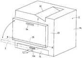
도1은 본 실시예의 화상 형성 장치(1)의 개략적인 종단 정면도이다. 도2는 전방 도어(외장 커버)(2)가 닫혀져 있는 화상 형성 장치(1)의 외관 사시도이다. 도3은 전방 도어(2)가 열려져, 제1 프로세스 카트리지(PY)가 도중까지 인출된 것을 나타내고 있는 화상 형성 장치(1)의 외관 사시도다.Fig. 1 is a schematic longitudinal front view of the
이 화상 형성 장치(1)는, 전자 사진 프로세스를 이용한 풀 컬러의 레이져 빔 프린터(4색 컬러)이며, 기록 매체에 컬러 화상 형성을 형성한다. 이러한 화상 형성 장치(1)는, 제1로부터 제4의 프로세스 카트리지(P(PY, PM, PC, PK))가 화상 형성 장치 본체(1A)에 대하여 착탈 가능하게 장착되는 프로세스 카트리지 착탈 방식 이다.This
이러한 화상 형성 장치(1)는, 전자 사진 프로세스를 이용한 풀 컬러의 레이져 빔 프린터(4색 컬러)이며, 기록 매체에 컬러 화상 형성을 형성한다.This
여기서, 실시예의 화상 형성 장치(1)에 관해서, 정면 측 또는 전방 측이라는 것은, 전방 도어(2)가 구비된 측이다. 배면 측 또는 안 측이라는 것은, 그 반대 측이다. 전후 방향이라는 것은, 배면 측으로부터 정면 측에 향하는 방향(앞 방향)과, 그 역방향(후 방향)이다. 좌우라는 것은, 정면 측으로부터 보아서 좌측 또는 우측이다. 좌우 방향이라는 것은, 오른쪽에서 좌측으로 향하는 방향(좌측 방향)과, 그 역의 방향(우측 방향)이다. 화상 형성 장치 본체(이하, 장치 본체라 한다)(1A)라는 것은, 프로세스 카트리지 이외의 화상 형성 장치 부분이다. 프로세스 카트리지(카트리지)(P) 또는 그 구성 부재, 혹은 장치 본체 측의 구성 부재에 관해서, 길이 방향이라는 것은, 화상 담체인 전자 사진 감광체 드럼(드럼)(3)의 축선 방향 혹은 그 축선 방향에 평행한 방향이다. 카트리지(P)의 길이 방향에 관해서, 장치 본체(1A)로부터의 구동력이 받아들여지는 측이 구동 측이며, 그 반대 측이 비 구동 측이다.Here, with respect to the
각 카트리지(P)를 수납하는 카트리지 수납부(1B)는 장치 본체(1A) 내의 중앙부에 설치되어 있다.The cartridge accommodating
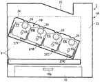
제1 ~ 제4 카트리지(P(PY, PM, PC, PK))는, 그 길이 방향을 전후 방향으로 하여 이러한 수납부(1B)에 수납되어 있으며, 우측 아래로 경사져 배열되어 있으며, 이미지 형성 장치에 위치되어 있다. 보다 구체적으로, 가장 좌측의 제1 카트리 지(PY)가 가장 높고, 제2 카트리지(PM)가 그보다 낮고, 제3 카트리지(PC)가 더 낮고, 가장 우측의 제4 카트리지(PK)가 가장 낮다.The first to fourth cartridges P (PY, PM, PC, and PK) are housed in such a
각 카트리지(P)가 수납부(1B)에서의 화상 형성 위치로 설정될 때에, 카트리지(P)의 드럼(3)의 회전 축(O)을 포함하는 가상 평면(E)이 존재한다. 상기 가상 평면(E)은 수평 평면(F)에 대하여 경사져 있으며, 이의 경사각은 θ이다. 본 실시예에서 그 경사각(θ)은 대략 20°이다. 그래서, 장치 본체(1A)의 수평 방향의 폭은 카트리지(P)를 경사지게 배열함으로써 억제될 수 있다.When each cartridge P is set to an image forming position in the
각 카트리지(P)는, 유사한 전자 사진 프로세스 기구를 가지며, 현상제(토너)의 색이나, 토너의 충전량이 각각 상이하다. 수납부(1B)에 있어서, 회전 구동력은 장치 본체(1A)로부터 화상 형성 위치에 장착된 각 카트리지(P)로 전달되고, 또한, 바이어스 전압(대전 바이어스 전압, 현상 바이어스 등)이 공급된다(도시 생략).Each cartridge P has a similar electrophotographic processing mechanism and differs in the color of the developer (toner) and the filling amount of the toner, respectively. In the
본 실시예의 각 카트리지(P)는, 드럼(3)과, 이 드럼(3)에 작용하는 프로세스 수단으로서의 대전 수단(4), 현상 수단(5), 클리닝 수단(6)을 카트리지 프레임체(7) 내에 일체적으로 포함한 것이다. 대전 수단(4)은 대전 롤러를 포함한다. 현상 수단(5)은 현상 롤러를 포함한다. 클리닝 수단(6)은 클리닝 블레이드를 포함한다.Each cartridge P of the present embodiment includes a
도4는 비 구동 측에서 본, 카트리지(P)의 외관 사시도다. 카트리지(P)는 드럼(3)의 축선방향 A-A로 연장된 어셈블리다. 드럼(3)의 길이 방향에 대한 일단 측과 타단부 측이 카트리지 프레임체(7)의 일단 측과 타단부 측에 배치된 제1 베어링 부재(비 구동 측)(7A)와 제2 베어링 부재(구동 측)(7B) 사이에 회전 가능하게 지지되어 있다.4 is an external perspective view of the cartridge P as seen from the non-drive side. The cartridge P is an assembly extending in the axial direction A-A of the
제1 카트리지(PY)는, 현상 용기 내에 노랑(Y) 색의 토너가 수용되어 있어, 드럼(3)의 면에 Y색의 토너 상을 형성한다. 제2 카트리지(PM)는, 현상 용기 내에 자홍(M) 색의 토너가 수용되어 있어, 드럼(3)의 면에 M색의 토너 상을 형성한다. 제3 카트리지(PC)는, 현상 용기 내에 청록(C) 색의 토너가 수용되어 있어, 드럼(3)의 면에 C색의 토너 상을 형성한다. 제4 카트리지(PK)는, 현상 용기 내에 검정(K) 색의 토너가 수용되어 있어, 드럼(3)의 면에 K색의 토너 상을 형성한다.In the first cartridge PY, yellow (Y) color toner is accommodated in the developing container, thereby forming a Y color toner image on the surface of the
각 카트리지(P)의 하방에는, 각 카트리지(P)의 드럼(3)에 대한 화상 정보 노광 수단으로서의 레이저 스캐너(8)가 배치되어 있다.Below each cartridge P, the
또한, 이 레이저 스캐너(8)의 하방에는, 급송 유닛(9)이 배치되어 있다. 이 급송 유닛(9)은, 기록 매체(전사재, 최종 기록 매체)(S)를 적재한 급지 카세트(10), 급지 롤러(11) 및 분리부(12), 레지스트 롤러 쌍(13) 등을 포함한다.In addition, the
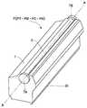
중간 전사 유닛(14)은 각 카트리지(P)의 상방에 배치되어 있다. 이 유닛(14)은, 각각의 카트리지(P(PY, PM, PC, PK))의 드럼(3)에 형성된 토너 상을 중간 전사 벨트((제1 기록 매체, 전사 벨트) 15)에 중첩시켜서 1차 전사하는 전사 수단을 포함한다. 이 유닛(14)은 평행 구동 롤러(16) 및 평행 텐션 롤러(17)를 포함하며,가요성 순환 전사 벨트(15)는 상기 롤러(16 와 17) 주변으로 연장되어 있다. 그리고, 전사 벨트(15)는 수평 방향에 대하여 경사져 배치되어 있는다.The
수납부(1B)에 있어서, 화상 형성 위치에 장착되어 있는 각 카트리지(P)의 드럼(3)의 상면은 전사 벨트(15)의 아래 부분의 하면에 접해 있다. 그 접촉부가 1차 전사부이다. 1차 전사 롤러(18)는 전사 벨트(15)의 내측에서 각 드럼(3)과 대향된 위치로 제공되어 있다. 전사 벨트(15)는 화살표의 반시계 방향으로 드럼(3)의 회전 속도에 대응한 속도로 구동 롤러(16)에 의해 이동한다. 규정된 1차 전사 전압은 1차 전사 롤러(18)에 규정된 제어 타이밍으로 인가된다. 2차 전사 롤러(19)는 전사 벨트(15)를 통해서 구동 롤러(16)를 향해 접촉된다. 2차 전사 롤러(19)와 전사 벨트(15)와의 접촉부가 2차 전사부이다. 규정된 2차 전사 전압은 규정된 제어 타이밍으로 2차 전사 롤러(19)에 인가된다.In the
정착(定着) 유닛(20) 및 배출 용지 유닛(21)은 장치 본체(1A) 내의 우측 상방부에 제공되어 있다. 장치 본체(1A)의 상면은 배출 용지 트레이(22)로 되어 있다.The fixing
풀 컬러 화상을 형성하기 위한 동작은 다음과 같다. 컨트롤러(제어 회로부,도시되지 않음)는 프린트 신호에 따라 화상 형성 장치의 화상 형성 동작을 개시시킨다. 즉, 제1 ~ 제4 각 카트리지(P(PY, PM, PC, PK))의 드럼(3)이 반시계 방향으로 규정된 속도로 회전된다. 전사 벨트(15)도 화살표의 시계 방향(드럼의 외주 면 이동에 순방향)으로 드럼(3)의 속도에 대응한 속도로 회전 구동된다. 레이저 스캐너(8)도 구동된다. 이 구동에 동기하고, 각 카트리지(P)에 있어서, 규정된 대전 전압이 인가된 대전 롤러(4)에 의해 드럼(3)의 표면은 규정된 극성의 규정된 전위로 균일하게 대전된다. 레이저 스캐너(8)는 각 드럼(3)의 표면을 각 색의 화상 정보 신호에 따라 변조된 레이저 빔(L(LY, LM, LC, LK))으로 주사 노광한다. 레이저 스캐너(8)로부터 출력된 레이저 빔(LY, LM, LC, LK)은, 각각, 대응하는 카트리 지(P)의 저면에 제공된 슬릿 창부(7a)를 통하여 카트리지 프레임체(7) 내로 진입하여 드럼(3)의 하면을 조사하며, 이에 의해, 각 드럼(3)의 표면에 대응 색의 화상 정보 신호에 따른 정전 잠상이 형성된다. 형성된 정전 잠상은 현상 롤러(5)에 의해 토너 상으로서 현상된다.The operation for forming a full color image is as follows. The controller (control circuit section, not shown) starts an image forming operation of the image forming apparatus in accordance with the print signal. That is, the
풀 컬러 화상의 노랑 성분에 대응하는 Y색 토너 상은 상기한 바와 같은 전자 사진 화상 형성 프로세스 동작에 의해, 제1 카트리지(PY)의 드럼(3)에 형성된다. 그리고, 그 토너 상이 전사 벨트(15) 위로 1차 전사된다. 마찬가지로, 풀 컬러 화상의 자홍 성분에 대응하는 M색 토너 상이 제2 카트리지(PM)의 드럼(3)에 형성된다. 그리고, 그 토너 상이, 전사 벨트(15) 위에 이미 전사되어 있는 Y색의 토너 상에 중첩되어서 1차 전사된다. 마찬가지로, 풀 컬러 화상의 청록 성분에 대응하는 C색 토너 상이 제3 카트리지(PC)의 드럼(3)에 형성된다. 그리고, 그 토너 상이, 전사 벨트(15) 위에 이미 전사되어 있는 Y색 + M색의 토너 상에 중첩되어서 1차 전사된다. 마찬가지로, 풀 컬러 화상의 검정 성분에 대응하는 K색 토너 상이제4 카트리지(PK)의 드럼(3)에 형성된다. 그리고, 그 토너 상이, 전사 벨트(15) 위에 이미 전사되어 있는 Y색 + M색 + C색의 토너 상에 중첩되어서 1차 전사된다.The Y color toner image corresponding to the yellow component of the full color image is formed in the
이와 같이 하여, 전사 벨트(15) 위로 Y색 + M색 + C색 + K색의 풀 컬러 토너 상이 전사 벨트(15) 위로 합성된다(미정착됨).In this way, a full color toner image of Y color + M color + C color + K color on the
각 카트리지(P)에 있어서, 1차 전사 후에 드럼(3)의 표면에 잔류한 전사 잔류 토너는 클리닝 블레이드(6)에 의해 제거된다.In each cartridge P, the transfer residual toner remaining on the surface of the
한편,급송 유닛(9)에 있어서, 급지 카세트(10)로부터 규정된 제어 타이밍으 로 기록 매체(제2 기록 매체)(S)가 분리되어 급송된다. 그 기록 매체(S)가, 레지스트 롤러 쌍(13)에 의한 규정된 제어 타이밍으로 2차 전사 롤러(19)와 전사 벨트(15) 사이의 접촉부인 2차 전사부로 도입된다. 또한, 규정된 2차 전사 전압은 2차 전사 롤러(19)에 인가된다. 이에 의해, 기록 매체(S)가 2차 전사부에 끼워져 반송되어 가는 과정에서, 전사 벨트(15) 상의 4색 중첩의 토너 상이 기록 매체(S)의 면에 순차적으로 함께 2차 전사된다.On the other hand, in the
기록 매체(S)는 전사 벨트(15)의 면으로부터 분리되고, 또한 상방으로 반송되어서 정착 유닛(20)에 도입되어, 정착 닙부에 의해 가열 및 가압된다. 이에 의해, 합성된 색 토너 상의 기록 매체(S)로의 정착이 이루어진다. 그리고, 기록 매체(S)는, 정착 유닛(20)을 나와, 풀 컬러 화상 프린트로서 배출 용지 유닛(21)에 의해 배출 용지 트레이(22) 위로 배출된다.The recording medium S is separated from the surface of the
《프로세스 카트리지 교환방식》 << process cartridge exchange method >>
장치 본체(1A)에 장착되어 있는 카트리지(P)에서, 화상 형성에 사용됨에 따라, 각각, 현상 수단에 수용되어 있는 토너가 소비된다. 그래서, 이러한 실시형태에서, 개개의 카트리지의 토너 잔량을 검지하는 검지 수단(도시 생략)을 카트리지에 제공한다. 컨트롤러는 상기 검지 수단으로 검지한 잔량 값을, 미리 설정한 카트리지 수명 예고나 수명 경고를 위한 임계치와 비교시킨다. 그리고, 상기 토너의 상기 잔량 값이 상기 임계치보다도 적은 잔량 값까지 감소한 카트리지에 대해서는, 표시부(도시 생략)에, 그 카트리지의 수명 예고 혹은 수명 경고를 표시시킨다. 이에 의해, 사용자에, 교환용의 카트리지의 준비를 재촉하거나, 혹은 카트리지의 교 환을 재촉하여, 출력 화상의 품질을 유지한다.In the cartridge P attached to the apparatus
본 실시예의 화상 형성 장치에 있어서, 카트리지(P)를 교환하는 경우, 장치 본체(1A)의 개폐 부재인 전방면 도어(2)는 도3에 도시된 바와 같이 개방된다(프론드 액세스 타입). 도면 부호 2a에 의해 표시된 것은 전방면 도어(2)에 제공되는 손잡이부이다. 급송 유닛(9)의 급지 카세트(10)도 프론트 액세스에 의해 출납된다. 도면 부호 10a에 의해 표시된 것은 급지 카세트(10)에 제공되는 손잡이부이다.In the image forming apparatus of this embodiment, when the cartridge P is replaced, the
장치 본체(1A) 내에 카트리지(P)를 삽입시키고, 장치 본체(1A) 내측으로부터 카트리지(P)를 취출하기 위해서, 개구(24 : 카트리지의 착탈을 행하기 위한 개구)가 장치 본체(1A)의 전면판(23)에 제공된다. 장치 본체(1A)에 대한 카트리지(P)의 착탈 방향은 드럼(3)의 축선 방향이다.In order to insert the cartridge P into the apparatus
장치 본체(1A)의 전면판(23)에는, 개구(24)를 덮어서 폐쇄하는 폐쇄 위치와 개구(24)를 해제하는 개방 위치 사이에서 이동 가능한 개폐 부재로서 전방면 도어(2)가 제공된다.The
본 실시예에 있어서, 전방면 도어(2)는 하부측에 제공되고 수평 방향으로 연장하는 도어 회전축(25 : 제1 회전축)을 중심으로 회전 가능하고, 개구(24)를 개방하는 개방 위치 및 개구(24)를 폐쇄하는 폐쇄 위치를 취할 수 있다. 도어 회전축(25)은 장치 본체(1A)의 전면판(23)에 제공된 베어링 부재(26)에 회전 가능하게 지지된다. 본 실시예에 있어서, 사용자의 도어 조작성을 고려하여, 도어 회전축(25)의 축선 방향(B-B)은 좌우 방향이고, 수평 방향이다. 전방면 도어(2)는 대 략 수직의 회전 각도 자세(폐쇄 위치)로부터 도어 회전축(25)을 중심으로 전방 측을 향해 대략 90도 회전되고, 이러한 자세는 대략 수평의 회전 각도 자세(개방 위치)이다.In this embodiment, the
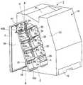
장치 본체(1A)의 카트리지 수납부(1B : 화상 형성 장치 본체의 내측)에는, 제1 내지 제4 카트리지(P : PY, PM, PC, PK)를 지지하는 제1 내지 제4 카트리지 지지 부재(27 : 27Y, 27M, 27C, 27K)가 제공된다. 도5는 카트리지 지지 부재(27 : 지지 부재)의 사시도이다.First to fourth cartridge support members (1 to 4th cartridge P: PY, PM, PC, PK) are supported in the
각각의 지지 부재(27)의 길이 방향은 전후 방향으로 정렬되고, 카트리지(P : PY, PM, PC, PK)의 배열 방향(우측이 아래)과 유사하게 비스듬하게 배치된다. 더 구체적으로, 가장 좌측의 제1 지지 부재(27Y)가 가장 높고, 제2 지지 부재(27M)가 그보다 낮고, 제3 지지 부재(27C)가 더 낮고, 가장 우측의 제4 지지 부재(27K)가 가장 낮다.The longitudinal direction of each
각각의 지지 부재(27)는 전방면 도어(2)의 개폐 이동에 연동되는 승강 기구에 의해, 카트리지(P)를 장치 본체(1A)에 대하여 화상 형성 위치에 위치시키는 제1 위치와 장치 본체(1A)에 대하여 착탈 가능한 착탈 위치에 위치 결정되는 제2 위치 사이에서 이동 가능하다. 또한, 드럼(7)은 제1 위치에서 전사 벨트(15)와 접촉한다. 또한, 드럼(7)은 제2 위치에서 전사 벨트(15)로부터 이격된다. 즉, 각각의 지지 부재(27)는 도어(2)가 폐쇄 상태에 위치할 때 드럼(7)이 전사 벨트(15)와 접촉하는 제1 위치 및 도어(2)가 개방 상태에 위치할 때 드럼(7)이 전사 벨트(15)로부터 이격되는 제2 위치를 취할 수 있다.Each supporting
각각의 지지 부재(27)의 이동 방향은 전술된 각각의 카트리지(P)의 배열 방향에 직교하는 방향이며, 각각 카트리지(P)는 이러한 방향으로 승강한다. 전방면 도어(2)의 개폐 이동에 연동하는 승강 기구가 이후 설명될 것이다.The moving direction of each
본 실시예에 있어서, 각각의 지지 부재(27)는 전방면 도어(2)의 폐쇄 회전에 연동하여 승강 기구에 의해 제1 위치로 상승된다. 또한, 각각의 지지 부재(27)는 전방면 도어(2)의 개방 회전에 연동하여 승강 기구에 의해 제2 위치로 하강된다.In this embodiment, each
도7 및 도12의 (a)는 각각의 지지 부재(27)의 상승 이동이 실행되어 제1 위치에 있는 상태를 도시한다. 이러한 상태에 있어서, 각각의 카트리지(P)의 제1 및 제2 베어링 부재(7A, 7B)의 상면 부분은 개별적으로 장치 본체(1A)의 전면판(23) 및 후면판(28)에 제공된 위치 결정부(29, 30 : 맞닿음부)에 압박되어 있다. 위치 결정부(29)는 L형의 절결 오목부를 가지고, 오목부는 카트리지의 위치 결정부인 제1 베어링 부재 및 제2 베어링 부재(7A, 7B) 상면의 원형면 부분과 결합한다. 이에 의해, 각각의 카트리지(P)는 장치 본체(1A)에 대하여 화상 형성 위치에 위치 결정되어 유지된다. 이러한 장착 위치에 있어서, 각각의 카트리지(P)의 드럼(3)의 상면은 도1에 도시된 바와 같이, 전사 벨트(15)의 하부 벨트 부분의 하면과 접촉하게 된다. 또한, 이러한 장착 위치에 있어서, 각각의 카트리지(P)에 대하여, 장치 본체(1A)로부터의 회전 구동력의 전달 및 바이어스 전압의 공급이 가능하다.7 and 12 (a) show a state in which the upward movement of each
도9 및 도12의 (b)는 각각의 지지 부재(27)가 제2 위치에 있는 상태를 도시한다. 이러한 상태에 있어서, 각각의 카트리지(P)의 제1 베어링 부재 및 제2 베어링 부재(7A, 7B)의 상면 부분은 개별적으로 장치 본체(1A)의 위치 결정부(29, 30) 로부터 이격되어 위치 결정부(29, 30)에 대한 압박을 해제시킨다. 이에 의해, 각각의 카트리지(P)는 장치 본체(1A)에 대하여 착탈 가능한 착탈 위치로 유지된다. 이러한 착탈 위치에 있어서, 각각의 카트리지(P)의 드럼(3)의 상면은 도10에 도시된 바와 같이, 전사 벨트(15)의 하부 부분의 하면으로부터 이격된다. 각각의 카트리지(P)에 대하여, 장치 본체(1A)로부터의 회전 구동력의 전달 및 바이어스 전압의 공급은 불가능하다.9 and 12 (b) show a state in which each
장치 본체(1A)에 대하여 착탈하는 경우에 있어서, 전방면 도어(2)는 도3에 도시된 바와 같이 충분히 개방되고, 개구(24)는 노출된다. 더 구체적으로, 각각의 지지 부재(27)는 전방면 도어(2)의 개방 회전에 연동하여 승강 기구에 의해 제1 위치로부터 제2 위치로 하강한다[도12의 (a)로부터 도12의 (b)로]. 이에 의해, 각각의 카트리지(P)는 장치 본체(1A)에 대하여 착탈 위치로 이동된다. 이러한 상태에서, 교환되어야 하는 카트리지(P)는 그를 지지하고 있는 지지 부재(27) 상에서 개구(24)를 통해 전방으로 미끄러져, 장치 본체(1A)로부터 취출된다. 카트리지(P)를 장치 주조립체 내부로 삽입하는 경우에 있어서, 카트리지(P)는 구동측이 선단측인 상태로 개구(24)를 통해 장치 본체(1A) 내부로 미끄러져 삽입된다.In the case of detaching with respect to the apparatus
카트리지(P)의 삽입은 카트리지(P)의 구동측이 장치 본체(1A)에 있어서의 후방측의 규제부(31)에 맞닿게 될 때까지 충분히 수행된다[(도12 (c) 참조].Insertion of the cartridge P is sufficiently performed until the drive side of the cartridge P is brought into contact with the restricting
도5 및 도6에 도시된 바와 같이, 길이 방향, 즉 착탈 방향을 따라 연장하는 홈(32 : 규제부)가 각각의 지지 부재(27)의 상면에 제공된다. 또한, 홈(32)에 대응하는 리브(33 : 도4 참조)가 카트리지(P)의 하면에 길이 방향으로 연장된다. 카트리지(P)의 착탈시, 카트리지(P)의 착탈 방향으로의 어긋남은 홈(32)과 리브(33) 사이의 결합에 의해 방지된다.As shown in Figs. 5 and 6, grooves 32 (regulators) extending in the longitudinal direction, i.e., the detachable direction, are provided on the upper surface of each
이러한 방식으로, 각각의 지지 부재(27)는 카트리지의 어긋남을 방지하는 안내 부재로서의 기능을 가진다. 또한, 각각의 지지 부재(27)는 하부 부분에서 카트리지(P)를 지지하여 카트리지를 밀어 올림으로써 카트리지(P)의 위치 결정부(7A, 7B)를 장치 본체(1A)의 위치 결정부(29, 30)에 접촉시킨다. 이에 의해, 카트리지(P)는 화상 형성이 가능한 장착 위치에 위치 결정되어 유지되어 진다.In this way, each
각각의 지지 부재(27)의 승강 기구 및 승강 기구와 전방면 도어(2) 사이의 연동 기구가 설명될 것이다.The lifting mechanism of each
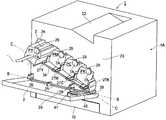
승강 기구와 전방면 도어(2) 사이의 연동 기구는 전방면 도어(2)에 연동하여 지지 부재(27)를 제1 위치와 제2 위치 사이에서 이동시키는 연결 부재(100)를 포함한다. 연결 부재(100)는 수평 방향으로 기운 제2 회전축을 중심으로 화상 형성 장치 본체에 대하여 회전 가능하다. 제1 내지 제4 지지 부재(27 : 27Y, 27M, 27C, 27K)는 연결 부재(100)에 의해 커플링된다. 연결 부재(100)는 연결축(34), 제1 아암 부재(35 : 제1 연결부) 및 링크 아암(40)을 포함한다. 연결축(34 : 제2 회전축)은 카트리지(P)를 장치 본체(1A)에 장착하는 방향으로부터 보는 경우, 전방면 도어(2)의 회전 축선(B-B)과 교차하는 축선(C-C)을 가진다. 제1 아암 부재(35) 및 링크 아암(40)은 연결축(34)에 고정되어 있다. 링크 아암(40)은 축선(C-C) 방향에 대하여 제1 아암 부재(35)보다도 전방면 도어(2)에 가까운 위치에서 연결축(34)에 고정되어 있다. 연결축(34)의 축선 방향(C-C)은 카트리지(P)의 승강 방향과 직교 한다. 즉, 이는 카트리지(P)의 배열 방향과 거의 평행하다. 연결축(34)은 장치 본체(1A)의 전면판(23)에 제공된 베어링 부재(도시 생략)에 회전 가능하게 지지된다. 지지 부재(27)의 전방 단부는 일체로 회전 가능한 제1 아암 부재(35) 및 연결축(34)을 통해 서로 연결된다. 지지 부재(27)의 전방 단부는 대응하는 아암 부재(35)에 대하여 연결축(36)을 중심으로 회전 가능하게 지지된다. 도11은 아암 부재(35)의 부분 확대도이다. 각각의 지지 부재(27)의 후방측 단부는 장치 본체(1A)에 링크(37)을 통해 연결되어 있다. 도면 부호 38에 의해 표시된 것은 장치 본체(1A)와 링크(37) 사이의 연결축이고, 도면 부호 39에 의해 표시된 것은 링크(37)와 지지 부재(27)의 후방측 단부 사이의 연결축이다. 각각의 지지 부재(27)에 있어서, 링크(37)의 축(38)과 축(39) 사이의 중심간 거리는 아암 부재(36)의 축(34)과 축(36) 사이의 중심간 거리와 동일하다.The linkage mechanism between the lifting mechanism and the
즉, 지지 부재(27)는 연결축(34), 아암 부재(36), 링크(37), 축(38) 및 축(39)을 연결시킴으로써 평행 4변형 링크 기구를 구성한다. 이러한 이유로, 각각의 지지 부재(27)는 연결축(34)의 회전에 의해 비스듬한 평행 이동을 하게 된다. 각각의 지지 부재(27)는 아암 부재(35)를 기립시키는 방향으로 회전시키는 연결축(34)에 의해 카트리지(P)를 도12의 (a)에 도시된 바와 같이 장치 본체(1A)에 대하여 화상 형성 위치(제1 위치)로 상승시킨다. 또한, 각각의 지지 부재(27)는 아암 부재(35)를 전방측으로 이동되는 방향으로 회전시키는 연결축(23)에 의해 카트리지(P)를 도12의 (b)에 도시된 바와 같이 장치 본체(1A)에 대하여 착탈 가능한 위치(제2 위치)로 하강시킨다. 이러한 방식으로, 연결축(34)은 각각의 지지 부 재(27)를 함께 동작시킨다. 전술된 승강 기구에 있어서, 제1 내지 제4 지지 부재(27)와 연결축(34) 사이의 모든 거리는 동일하고, 동작이 공통으로 이루어져서, 기구가 단순하게 되어 오동작이나 고장이 쉽게 야기되지 않게 할 수 있다. 또한, 쓸데없는 공간이 불필요하게 되기 때문에, 장치의 소형화도 달성될 수 있다. 또한, 각 색마다 다른 부품을 사용할 필요가 없기 때문에, 부품의 공통화도 달성될 수 있고 이는 비용적으로도 유리하다. That is, the
전술된 승강 기구에 의한 제1 내지 제4 지지 부재(27)의 승강은 전방면 도어(2)의 개폐 동작에 연동하여 수행된다.The lifting of the first to fourth supporting
더 구체적으로는, 축(34)에 대하여 실질적으로 직교하는 방향으로 연장되는 제2 연결부(40 : 링크 아암)는 연결축(34)과 일체로 회전하도록 연결축(34)의 우측 단부에 고정된다. 또한, 링크 아암(40)의 자유 단부는 전방면 도어(2)의 내측에 제공된 결합부(41 : 박스형부)에 의해 둘러싸여져, 전방면 도어(2)와 결합하고 있다.More specifically, the second connecting portion 40 (link arm) extending in a direction substantially perpendicular to the
전방면 도어(2)가 개방 위치로부터 폐쇄 위치로 도어 회전축(25)을 중심으로 회전하는 경우, 링크 아암(40)의 자유 단부는 전방면 도어(2)의 압박부(2a : 내측면, 도3 참조)에 의해 밀려져, 연결축(34)을 회전시킨다.When the
여기서, 전방면 도어(2)의 회전 축인 도어 회전축(25 : 축선B-B) 및 연결축(34 : 축선C-C)은 서로 평행하지 않고, 그 각도가 서로 다르다. 즉, 제2 회전축인 연결축(34)은 카트리지(P)의 착탈 방향과 직교하고, 제1 회전축인 도어 회전축(25)과 다른 각도를 가진다. 따라서, 링크 아암(40)의 자유 단부와 전방면 도 어(2)의 내측면(2a) 사이의 접촉부는 전방면 도어(2)의 내측면(2a) 상에서 활 형상 곡선을 따라 이동한다. 이러한 관점에서, 링크 아암(40)의 자유 단부를 둘러싸는 박스형부(41)와 관련하여, 이러한 링크 아암(40)의 활형 이동 범위에 대하여 자유도가 주어진다. 박스형부(41)는, 전방면 도어(2)가 폐쇄 위치로부터 개방 위치로 회전하는 경우에 링크 아암(40)이 전방면 도어(2)의 개방 동작을 추종하여 연결축(34)을 회전시켜서 카트리지(P)를 착탈 위치로 이동시키도록, 링크 아암(40)과 전방면 도어(2)를 결합시키는 기능을 가진다.Here, the door rotating shaft 25 (axis B-B) and the connecting shaft 34 (axis C-C), which are the rotating shafts of the
따라서, 도어 회전축(25)과 연결축(34)이 서로 평행하지 않은 구조에 있어서, 지지 부재(27)는 전방면 도어(2)의 개폐 동작에 연동하여 일체적으로 승강이 이루어지고, 제1 위치와 제2 위치 사이에서의 절환이 가능하게 된다.Therefore, in the structure in which the
즉, 본 실시예의 화상 형성 장치에 있어서, 전방면 도어(2)의 도어 회전축(25 : 제1 회전축)이 수평이기 때문에, 조작성이 향상될 수 있다. 또한, 카트리지(P)의 배열 방향에 평행한 1개의 연결축(34 : 제2 회전축)이 컴팩트하게 지지 부재(27)의 승강을 행하므로, 장치의 소형화 및 단순화도 달성될 수 있다.That is, in the image forming apparatus of the present embodiment, since the door rotation shaft 25 (first rotation shaft) of the
또한, 카트리지(P)의 제1 위치와 제2 위치 사이의 절환이 전방면 도어(2)의 개폐 동작에 연동하고 이루어지기 때문에, 카트리지 교환에 있어서의 유지 보수성도 우수하다.In addition, since the switching between the first position and the second position of the cartridge P is made in conjunction with the opening / closing operation of the
링크 아암(40)은 축선(C-C) 방향에 대하여 제1 아암 부재(35)보다도 전방면 도어(2)에 가까운 위치에서 연결축(34)에 고정된다. 링크 아암(40)을 전방면 도어(2)에 가까운 위치에 배치함으로써, 링크 아암(40)을 소형화하는 것이 가능해 지고,화상 형성 장치(1)의 소형화가 달성될 수 있다.The
[제2 실시예]Second Embodiment
도13은 제2 실시예에 관한 화상 형성 장치(1)를 도시하는 개략 사시도이다. 도14는 도13의 부분적 확대도이고, 도15a는 도14의 부분적 확대도이다. 본 실시예에서, 제1 실시예와 동일한 도면부호는 본 실시예에서 대응하는 기능을 갖는 요소에 할당되고, 간단하게 하기 위해, 그 상세한 설명은 생략된다.Fig. 13 is a schematic perspective view showing the
화상 형성 장치(1)에서, 개폐 부재인 전방면 도어(2)가 열림 상태로 위치될 때, 전방면 도어(2)는 개구부(24)보다 화상 형성 장치 본체(1A)의 외측으로 연장된다. 카트리지(P)의 착탈 시에, 카트리지(P)의 적어도 일부를 적재해서 화상 형성 장치 본체(1A)의 내측으로 안내하는 적재 부재인 연장 안내 부재(42)가 구비된다. 이러한 연장 안내 부재(42)는, 화상 형성 장치 본체(1A)에 회전 가능하게 제공되고, 전방면 도어(2)가 닫힘 상태로 위치될 때 전방면 도어(2)의 내측에 수납된다. 이하, 이것에 대해서 설명한다.In the
화상 형성 장치(1)에서, 연장 안내 부재(42)는 연결축(34)에 회전 가능하게 장착된다. 이러한 실시예에서, 링크 아암(40)은 제1 링크 아암(40A)과, 제2 링크 아암(40B)으로 분할된다. 제1 링크 아암(40A)은 연결축(34)과 일체로 회전하도록 연결축(34)에 고정된다. 제2 링크 아암(40B)은 연장 안내 부재(42)와 일체로 장착된다. 제2 링크 아암(40B)의 자유 단부(제1 결합부)는 전방면 도어(2)의 내측에 제공된 제3 결합부인 상자형 형상부(41)로 둘러싸여 전방면 도어(2)와 결합한다. 전방면 도어(2)에 연동해서 지지 부재(27)를 제1 위치와 제2 위치 사이에서 이동시 키는 연결 부재(200)에는, 제2 회전축[연결축(34)]과 일체로 회전하고 지지 부재(27)와 결합하는 제1 아암 부재(40A)가 제공된다. 또한, 연결 부재(200)에는, 연결축(34)과 일체로 회전하고 전방면 도어(2)와 결합하는 제2 링크 아암(40B)이 제공된다.In the
즉, 본 실시예에서, 도15b에 도시한 바와 같이 연결 부재(200)는 연결축(34)과, 제1 아암 부재(35) 및 제1 링크 아암(40A)을 포함한다.That is, in this embodiment, as shown in Fig. 15B, the connecting
전방면 도어(2)가 열림 상태로부터 닫힘 상태로 도어 회전축(25)에 대해 회전되면, 제2 링크 아암(40B)의 자유 단부는 연장 안내 부재(42)가 연결축(34)에 대해 폐쇄 방향으로 회전하도록 전방면 도어(2)의 압박부[내측면(2a)]에 의해 밀어진다. 전방면 도어(2)의 회전축인 도어 회전축(25)과 연결축(34)은 서로 평행하지 않고 다른 각도를 갖기 때문에, 제2 링크 아암(40B)의 자유 단부와 전방면 도어(2)의 내측면(2a) 사이의 접촉부는 전방면 도어(2)의 내측면(2a) 위를 호형 곡선을 따라 이동한다. 전방면 도어(2)가 닫힘에 따라, 제2 링크 아암(40B)의 후단부(제2 결합부)가 제1 링크 아암(40B)의 자유 단부에 대응하여 접촉된다. 이에 의해, 연결축(34)을 회전시키는 힘이 작용한다.When the
전방면 도어(2)가 닫힘 상태로부터 열림 상태로 이동할 때, 연장 안내 부재(42)에 제공된 결합부인 보스(42b)(제2 결합부)가 제1 링크 아암(40A)과 결합한다. 이는 지지 부재(27)를 제1 위치로부터 제2 위치로 이동시키도록 연결축(34)을 회전시킨다. 달리 말하면, 연장 안내 부재(42)는, 전방면 도어(2)가 닫힘 상태로부터 열림 상태로 이동할 때, 연결 부재(40A)와 결합하여 연결 부재(40A)를 회전시 키는 보스(42b)를 갖는다.When the
또한, 연장 안내 부재(42)는 전방면 도어(2)의 열림 상태에서, 지지 부재(27)와 동일면 상에서 장치 본체(1A)의 외측으로 사실상 연장되고, 카트리지(P)의 장착 시, 카트리지(P)의 적어도 일부를 적재하고, 착탈 개구부(24)로 운반된다.Further, the
연장 안내 부재(42)는 전방면 도어(2)의 닫힘 상태 시에 있어서는, 전방면 도어(2)의 내측에 수납된다.The
연장 안내 부재(42)에는 안내부인 구획판(42a)이 제공되고, 카트리지(P)의 삽입 분리 중에, 카트리지(P)의 일부를 적재해서 장치 본체(1A)의 내측 또는 외측으로 안내한다. 또한, 사용자가 카트리지(P)를 삽입하는 경우에 삽입 타겟을 제공한다.The
본 실시예에서는, 전방면 도어(2)를 폐쇄함으로써, 연장 안내 부재(42)도 폐쇄될 수 있고, 또한 카트리지 (P)는 장치 본체(1A)의 위치 결정부(29, 30)에 위치될 수 있다. 따라서, 전술한 제1 실시예의 화상 형성 장치보다 카트리지의 유지 보수성, 조작성이 향상된다. 또한, 본 실시예에서, 연장 안내 부재(42)를 통해 전방면 도어(2)와 연결 부재(200) 사이의 연결이 행해진다. 따라서, 연결 부재(200)를 작게 제조할 수 있고, 화상 형성 장치(1)는 소형화될 수 있다. 그 밖의 효과는 제1 실시예와 같다.In this embodiment, by closing the
[제3 실시예]Third Embodiment
도16은 제3 실시예에 관한 화상 형성 장치의 설명도이다. 본 실시예의 설명에서, 제1 및 제2 실시예와 동일한 도면부호는 본 실시예에서 대응하는 기능을 갖 는 요소에 할당되고, 간단하게 하기 위해, 그 상세한 설명은 생략된다. 도면부호 43은 전방면 도어(2)의 내측에 배치된 적재 부재인 내부 도어이다. 이러한 내부 도어(32)는 연결축(34)과 평행한 회전축(44)에 대해 장치 본체(1A)의 개구부(24)에 대하여 개폐 회전할 수 있다. 내부 도어(43)의 폐쇄 동작 중에, 연결축(34)과 일체로 회전하는 제1 링크 아암(40A)은 내부 도어(43)의 제2 링크 아암(40B)과 결합하고, 내부 도어(43)의 폐쇄 동작에 연동해서 지지 부재 연결축(34)을 회전시킨다.16 is an explanatory diagram of an image forming apparatus according to the third embodiment. In the description of this embodiment, the same reference numerals as in the first and second embodiments are assigned to elements having corresponding functions in this embodiment, and for the sake of simplicity, the detailed description is omitted.
도16의 (a)는, 카트리지(P)가 장치 본체(1A) 내에 길이 방향으로 소정의 위치까지 압입되지 않고, 내부 도어(43) 위에 남아있는 상태를 나타낸다. 이러한 상태에서, 전방면 도어(2)가 닫힐 때, 내부 도어(43)에 의해 카트리지(P)는 장치 본체(1A) 내에 소정의 위치까지 압입된다. 그 후에, 연결축(34)은 연속 내부 도어(43)의 폐쇄 동작에 연동해서 회전되어, 지지 부재(27)가 지연되어 제1 위치[도16의 (b) 내지 (c)]로 상승한다.Fig. 16A shows a state in which the cartridge P remains on the
이에 의해, 전방면 도어(2)가 카트리지(P)의 장치 본체(1A) 내측으로의 삽입이 불완전한 상태에서 닫히더라도, 확실하게 카트리지(P)의 위치 결정이 이루어진다.Thereby, even if the
도16의 (a)에서, 전방면 도어(2)와 내부 도어(43)가 열림 상태이고, 이러한 상태에서 제1 링크 아암(40A)과 제2 링크 아암(40B)은 내부 도어(43)가 닫히는 방향으로 결합되지 않는다. 연결 부재는 제2 실시예와 동일한 구성이다. 즉, 도15b에 도시한 바와 같이 연결 부재(200)는 연결축(34), 제1 아암 부재(35) 및 제1 링크 아암(40A)을 포함한다.In Fig. 16A, the
도16의 (b)에서 전방면 도어(2)와 내부 도어(43)는 폐쇄 동작 중의 상태이다. 이러한 상태에서, 내부 도어(43)가 소정량 닫힐 때, 제2 링크 아암(40B)은 연결 부재(40A)와 사면에서 결합한다. 이 때, 카트리지(P)는 내부 도어(43)에 압입되어, 장치 본체(1A) 내로 이동한다.In Fig. 16B, the
도16의 (c)는 전방면 도어(2)와 내부 도어(43)는 닫힘 상태이고, 제2 링크 아암(40B)과 제1 링크 아암(40A)이 서로 결합하고, 그 다음에 내부 도어(43)의 폐쇄 동작에 연동해서 연결축(34)이 회전되어, 지지 부재(27)가 제2 위치로부터 제1 위치로 상승한다. 이에 의해, 카트리지(P)는 상하 방향으로 위치 결정이 이루어진다.16 (c) shows that the
즉, 본 실시예의 화상 형성 장치는 내부 도어(43)의 폐쇄 동작과, 지지 부재(27)의 상승 동작 사이에 시간차가 제공된다.That is, in the image forming apparatus of this embodiment, a time difference is provided between the closing operation of the
또한 본 실시예에서, 전방면 도어(2)가 폐쇄됨으로써, 내부 도어(43)가 폐쇄되고, 또한 카트리지(P)는 장치 본체(1A)의 위치 결정부(29, 30)에 위치될 수 있다. 따라서, 전술의 제1 실시예의 화상 형성 장치보다, 카트리지의 유지 보수성과 조작성이 향상된다. 또한, 본실시예에서, 내부 도어(43)를 통해, 전방면 도어(2)와 연결 부재(200) 사이의 연결을 행한다. 따라서, 연결 부재(200)를 작게 할 수 있으며, 화상 형성 장치(1)를 소형화할 수 있다. 그 밖의 효과는 제1 실시예와 같다.Also in this embodiment, the
[제4 실시예][Example 4]
도17은 제4 실시예에 관한 화상 형성 장치의 설명도이다. 전방면 도어(2)의 도어 회전축(25)은 이러한 화상 형성 장치(1)의 수직 방향으로 연장된다. 이러한 실시예의 설명에서, 제1 또는 제2 실시예와 동일한 도면부호는 본 실시예에서 대응하는 기능을 갖는 요소에 할당되고, 간단하게 하기 위해, 그 상세한 설명은 생략된다.17 is an explanatory diagram of an image forming apparatus according to the fourth embodiment. The
전술한 제1 내지 제4 실시예의 화상 형성 장치에서는 4개의 카트리지(P)가 사용되지만, 본 발명은 2개 이상의 복수개의 카트리지를 이용하는 화상 형성 장치에 적용 가능하다.Although four cartridges P are used in the image forming apparatuses of the first to fourth embodiments described above, the present invention is applicable to an image forming apparatus using two or more cartridges.
또한, 화상 담지 부재는 전자 사진 감광체에 한정되지 않고, 정전기록 유전체 및 자기 기록 자성체 등일 수 있다.The image bearing member is not limited to the electrophotographic photosensitive member, but may be an electrostatic lock dielectric, a magnetic recording magnetic body, or the like.
또한, 기록 매체(S)를 유지해서 반송하는 기록 매체 반송 전사 벨트가 중간 전사 벨트 대신에 사용될 수 있고, 각 카트리지의 화상 담지 부재에 형성되는 토너 상은 기록 매체의 표면에 순차적으로 중첩해서 전사된다.In addition, a recording medium conveyance transfer belt for holding and conveying the recording medium S can be used in place of the intermediate transfer belt, and the toner image formed on the image bearing member of each cartridge is sequentially transferred onto the surface of the recording medium.
본 발명의 실시예에 따라, 프로세스 카트리지 교환에 관한 조작성의 향상과, 화상 형성 장치 본체의 소형화 및 단순화가 달성될 수 있다.According to the embodiment of the present invention, the improvement of the operability regarding the process cartridge replacement and the miniaturization and simplification of the image forming apparatus main body can be achieved.
본 발명은 본원에 개시된 구조를 참조하여 설명되었지만, 전술한 세부 사항에 한정되지 않고, 첨부된 청구항의 범주 또는 개선을 위한 목적 내에서 이루어질 수 있는 변경 또는 변형을 커버하도록 적용될 수 있다.Although the present invention has been described with reference to the structures disclosed herein, it is not limited to the foregoing details and may be applied to cover changes or modifications that may be made within the scope or spirit of the appended claims.
도1은 제1 실시예의 화상 형성 장치를 개략적으로 나타내는 종단 정면도.1 is a longitudinal sectional front view schematically showing the image forming apparatus of the first embodiment;
도2는 전방 도어가 닫혀져 있는 화상 형성 장치의 외관 사시도.Fig. 2 is an external perspective view of the image forming apparatus in which the front door is closed.
도3은 전방 도어가 열려져서, 제1 프로세스 카트리지가 도중까지 인출된 것을 나타내는 화상 형성 장치의 외관 사시도.Fig. 3 is an external perspective view of the image forming apparatus showing that the front door is opened and the first process cartridge is pulled out halfway.
도4는 카트리지를 비 구동 측으로부터 본 외관 사시도.4 is an external perspective view of the cartridge as seen from the non-drive side;
도5는 제1 ~ 제4 카트리지 지지 부재의 사시도(도어 폐쇄 상태 시).Fig. 5 is a perspective view of the first to fourth cartridge support members (in the door closed state).
도6은 제1 ~ 제4 카트리지 지지 부재의 사시도(도어 개방 상태 시).Fig. 6 is a perspective view of the first to fourth cartridge support members (in the door open state).
도7은 각 카트리지가 장착 위치에 위치 결정되어 있는 상태를 도시한 도면.Fig. 7 is a diagram showing a state where each cartridge is positioned at the mounting position.
도8은 각 카트리지의 위치 결정부와 장치 본체 측의 위치 결정부를 나타내는 도면.Fig. 8 is a diagram showing a positioning portion of each cartridge and a positioning portion on the apparatus main body side.
도9는 각 카트리지가 착탈 위치에 위치 결정되어 있는 상태를 도시한 도면.Fig. 9 is a diagram showing a state where each cartridge is positioned at a detachable position.
도10은 각 카트리지가 착탈 위치에 위치하고 있어 감광체 드럼이 중간 전사 벨트로부터 떨어져 있는 상태를 도시한 도면.Fig. 10 is a view showing a state in which each cartridge is located at a detachable position so that the photosensitive drum is separated from the intermediate transfer belt.
도11은 아암 부재 부분의 확대도.11 is an enlarged view of an arm member portion.
도12는 카트리지 지지 부재의 동작과, 카트리지의 장착 및 삽입 분리를 나타내는 도면.Figure 12 illustrates the operation of the cartridge support member and the mounting and insertion removal of the cartridge.
도13은 전방 도어가 열려져 제3 프로세스 카트리지가 도중까지 인출된 것을 나타내고 있는, 제2 실시예의 화상 형성 장치의 외관 사시도.Fig. 13 is an external perspective view of the image forming apparatus of the second embodiment, showing that the front door is opened and the third process cartridge is drawn out to the middle;
도14는 도13의 부분 확대도.14 is a partially enlarged view of FIG. 13;
도15a는 도14의 부분 확대도.15A is an enlarged partial view of FIG.
도15b는 연결 부재, 카트리지 지지 부재의 사시도.Fig. 15B is a perspective view of the connecting member and the cartridge supporting member.
도16은 제3 실시예의 화상 형성 장치를 나타내는 도면.Figure 16 shows an image forming apparatus in a third embodiment.
도17은 전방 도어가 열려져, 제4 프로세스 카트리지가 도중까지 인출된 것을 나타내는, 제4 실시예의 화상 형성 장치의 외관 사시도.Fig. 17 is an external perspective view of the image forming apparatus of the fourth embodiment, showing that the front door is opened and the fourth process cartridge is pulled out halfway.
*도면의 주요 부분에 대한 부호의 설명** Description of the symbols for the main parts of the drawings *
1: 화상 형성 장치1: image forming apparatus
3: 드럼3: drum
4: 대전 수단4: charging means
5: 현상 수단5: developing means
6: 클리닝 수단6: cleaning means
7: 프레임체7: frame
8: 스캐너8: scanner
9: 급송 유닛9: feeding unit
10: 급지 카세트10: paper feed cassette
11: 급지 롤러11: feed roller
12: 분리부12: separator
13: 레지스트 롤러 쌍13: resist roller pair
Claims (13)
Translated fromKoreanApplications Claiming Priority (4)
| Application Number | Priority Date | Filing Date | Title |
|---|---|---|---|
| JPJP-P-2007-00129252 | 2007-05-15 | ||
| JP2007129252 | 2007-05-15 | ||
| JP2008077497AJP5137647B2 (en) | 2007-05-15 | 2008-03-25 | Image forming apparatus |
| JPJP-P-2008-00077497 | 2008-03-25 |
Publications (2)
| Publication Number | Publication Date |
|---|---|
| KR20080101742A KR20080101742A (en) | 2008-11-21 |
| KR100955971B1true KR100955971B1 (en) | 2010-05-04 |
Family
ID=40124840
Family Applications (1)
| Application Number | Title | Priority Date | Filing Date |
|---|---|---|---|
| KR1020080045132AActiveKR100955971B1 (en) | 2007-05-15 | 2008-05-15 | Image forming apparatus |
Country Status (4)
| Country | Link |
|---|---|
| US (2) | US8254805B2 (en) |
| JP (1) | JP5137647B2 (en) |
| KR (1) | KR100955971B1 (en) |
| CN (1) | CN101308358B (en) |
Families Citing this family (41)
| Publication number | Priority date | Publication date | Assignee | Title |
|---|---|---|---|---|
| JP5159225B2 (en)* | 2007-09-21 | 2013-03-06 | キヤノン株式会社 | Image forming apparatus |
| US8135305B2 (en)* | 2007-10-18 | 2012-03-13 | Canon Kabushiki Kaisha | Image forming apparatus |
| JP5230265B2 (en)* | 2008-05-23 | 2013-07-10 | キヤノン株式会社 | Image forming apparatus and process cartridge |
| JP2010102175A (en)* | 2008-10-24 | 2010-05-06 | Canon Inc | Image forming apparatus |
| JP5241448B2 (en)* | 2008-11-27 | 2013-07-17 | キヤノン株式会社 | Process cartridge and image forming apparatus |
| JP2010190930A (en)* | 2009-02-16 | 2010-09-02 | Konica Minolta Business Technologies Inc | Image forming apparatus |
| US8380104B2 (en) | 2009-03-19 | 2013-02-19 | Fuji Xerox Co., Ltd. | Replacement unit and image forming device |
| JP4793466B2 (en)* | 2009-03-19 | 2011-10-12 | 富士ゼロックス株式会社 | Image forming apparatus |
| JP5565011B2 (en)* | 2010-03-16 | 2014-08-06 | 富士ゼロックス株式会社 | Image forming apparatus |
| JP5539037B2 (en) | 2010-06-02 | 2014-07-02 | キヤノン株式会社 | Electrophotographic image forming apparatus |
| JP5321625B2 (en)* | 2011-03-18 | 2013-10-23 | コニカミノルタ株式会社 | Image forming apparatus |
| JP5725338B2 (en) | 2011-03-25 | 2015-05-27 | 富士ゼロックス株式会社 | Image forming apparatus |
| JP5838610B2 (en)* | 2011-06-27 | 2016-01-06 | ブラザー工業株式会社 | Image forming apparatus |
| JP5901327B2 (en)* | 2012-02-09 | 2016-04-06 | キヤノン株式会社 | Developing device, process cartridge, and image forming apparatus |
| JP6071248B2 (en)* | 2012-05-22 | 2017-02-01 | キヤノン株式会社 | Electrophotographic image forming apparatus |
| JP5650177B2 (en) | 2012-09-13 | 2015-01-07 | 株式会社沖データ | Image forming apparatus |
| JP6061599B2 (en)* | 2012-10-01 | 2017-01-18 | キヤノン株式会社 | Image forming apparatus |
| JP2014202844A (en)* | 2013-04-03 | 2014-10-27 | シャープ株式会社 | Image forming apparatus |
| US9291988B2 (en)* | 2013-04-03 | 2016-03-22 | Sharp Kabushiki Kaisha | Image forming apparatus including cartridge position detector |
| JP2014202847A (en)* | 2013-04-03 | 2014-10-27 | シャープ株式会社 | Image forming apparatus |
| JP6413435B2 (en)* | 2014-07-25 | 2018-10-31 | 富士ゼロックス株式会社 | Image forming apparatus |
| JP6316134B2 (en)* | 2014-07-30 | 2018-04-25 | キヤノン株式会社 | Image forming apparatus |
| JP6425189B2 (en) | 2014-10-07 | 2018-11-21 | 富士ゼロックス株式会社 | Image forming device |
| WO2016065029A1 (en)* | 2014-10-21 | 2016-04-28 | Brackett Jaclyn | Photoluminescent activator apparatus, photoluminescent composition, method of making and using the same |
| JP6555967B2 (en)* | 2015-07-31 | 2019-08-07 | キヤノン株式会社 | Image forming apparatus |
| JP6665597B2 (en)* | 2016-03-08 | 2020-03-13 | 富士ゼロックス株式会社 | Developer container and image forming apparatus |
| US10023309B2 (en) | 2016-04-15 | 2018-07-17 | James Brown | Remote controlled aircraft |
| JP6786355B2 (en)* | 2016-10-31 | 2020-11-18 | キヤノン株式会社 | Image forming device |
| US10496034B2 (en)* | 2016-11-01 | 2019-12-03 | Canon Kabushiki Kaisha | Image forming apparatus |
| JP6849396B2 (en)* | 2016-11-01 | 2021-03-24 | キヤノン株式会社 | Image forming device |
| JP7046537B2 (en)* | 2016-11-01 | 2022-04-04 | キヤノン株式会社 | Image forming device |
| WO2019044143A1 (en)* | 2017-08-31 | 2019-03-07 | 京セラドキュメントソリューションズ株式会社 | Unit housing and image formation device |
| JP7095242B2 (en)* | 2017-09-12 | 2022-07-05 | セイコーエプソン株式会社 | Printing equipment |
| JP2018028684A (en)* | 2017-10-20 | 2018-02-22 | シャープ株式会社 | Image forming apparatus |
| KR102264525B1 (en) | 2018-04-19 | 2021-06-14 | 휴렛-팩커드 디벨롭먼트 컴퍼니, 엘.피. | structure for detecting remaining developer in the developer cartridge |
| JP7246902B2 (en)* | 2018-11-29 | 2023-03-28 | キヤノン株式会社 | image forming device |
| JP7254548B2 (en)* | 2019-02-13 | 2023-04-10 | キヤノン株式会社 | image forming device |
| JP2020148881A (en)* | 2019-03-13 | 2020-09-17 | ブラザー工業株式会社 | Image forming device |
| JP7237699B2 (en)* | 2019-03-29 | 2023-03-13 | キヤノン株式会社 | image forming device |
| JP7230796B2 (en)* | 2019-12-26 | 2023-03-01 | ブラザー工業株式会社 | image forming device |
| US11226574B1 (en)* | 2020-12-10 | 2022-01-18 | Toshiba Tec Kabushiki Kaisha | Image forming apparatus |
Citations (4)
| Publication number | Priority date | Publication date | Assignee | Title |
|---|---|---|---|---|
| JPH08220824A (en)* | 1995-02-17 | 1996-08-30 | Konica Corp | Color image forming device |
| JPH1078736A (en) | 1996-09-02 | 1998-03-24 | Ricoh Co Ltd | Image forming device |
| JP2003162203A (en) | 2001-09-13 | 2003-06-06 | Canon Inc | Unit, developing cartridge, process cartridge, toner cartridge, and electrophotographic image forming apparatus |
| JP2004212986A (en) | 2002-12-20 | 2004-07-29 | Ricoh Co Ltd | Image forming apparatus and process cartridge |
Family Cites Families (22)
| Publication number | Priority date | Publication date | Assignee | Title |
|---|---|---|---|---|
| US5608498A (en) | 1995-02-03 | 1997-03-04 | Konica Corporation | Image forming apparatus in which at least an image carrying member and plural exposure means are constructed in a single body |
| JP3854708B2 (en)* | 1997-02-28 | 2006-12-06 | キヤノン株式会社 | Color image forming apparatus |
| US6157792A (en) | 1998-03-31 | 2000-12-05 | Canon Kabushiki Kaisha | Electrophotographic apparatus having plural image forming modes, and a process cartridge applied to such electrophotographic apparatus |
| JP2001066968A (en)* | 1999-08-31 | 2001-03-16 | Canon Inc | Image forming device |
| JP2001272864A (en)* | 2000-03-27 | 2001-10-05 | Canon Inc | Image forming device |
| CN100407065C (en) | 2002-12-20 | 2008-07-30 | 株式会社理光 | Imager |
| JP4025663B2 (en)* | 2003-03-04 | 2007-12-26 | 松下電器産業株式会社 | Image carrier attaching / detaching mechanism and color image forming apparatus having the same |
| JP4343641B2 (en)* | 2003-10-03 | 2009-10-14 | 株式会社リコー | Power feeding face plate and image forming apparatus |
| JP4616591B2 (en)* | 2004-07-20 | 2011-01-19 | 株式会社リコー | Image forming apparatus |
| JP4307369B2 (en) | 2004-12-07 | 2009-08-05 | キヤノン株式会社 | Charging device, process cartridge, and image forming apparatus |
| JP4134984B2 (en)* | 2004-12-27 | 2008-08-20 | ブラザー工業株式会社 | Image forming apparatus |
| JP2006220993A (en)* | 2005-02-10 | 2006-08-24 | Canon Inc | Image forming apparatus |
| JP4577578B2 (en)* | 2005-12-20 | 2010-11-10 | 富士ゼロックス株式会社 | Image forming apparatus, image forming structure, mounting method of image forming structure, and drawing method of image forming structure |
| JP4241819B2 (en)* | 2006-01-11 | 2009-03-18 | キヤノン株式会社 | Color electrophotographic image forming apparatus |
| JP4709133B2 (en)* | 2006-01-11 | 2011-06-22 | キヤノン株式会社 | Electrophotographic image forming apparatus |
| JP4280770B2 (en)* | 2006-01-11 | 2009-06-17 | キヤノン株式会社 | Process cartridge and electrophotographic image forming apparatus |
| JP4280769B2 (en)* | 2006-01-11 | 2009-06-17 | キヤノン株式会社 | Electrophotographic image forming apparatus |
| US7486907B2 (en)* | 2006-01-11 | 2009-02-03 | Canon Kabushiki Kaisha | Electrophotographic image forming apparatus including a tray for carrying a process cartridge |
| JP5084257B2 (en)* | 2006-12-28 | 2012-11-28 | キヤノン株式会社 | Process cartridge and image forming apparatus using the same |
| JP5159176B2 (en)* | 2007-06-15 | 2013-03-06 | キヤノン株式会社 | Image forming apparatus |
| JP4459295B1 (en)* | 2008-09-29 | 2010-04-28 | キヤノン株式会社 | Color electrophotographic image forming apparatus |
| JP5293753B2 (en)* | 2011-01-14 | 2013-09-18 | ブラザー工業株式会社 | Image forming apparatus |
- 2008
- 2008-03-25JPJP2008077497Apatent/JP5137647B2/ennot_activeExpired - Fee Related
- 2008-05-09USUS12/118,198patent/US8254805B2/enactiveActive
- 2008-05-15KRKR1020080045132Apatent/KR100955971B1/enactiveActive
- 2008-05-15CNCN2008100992444Apatent/CN101308358B/ennot_activeExpired - Fee Related
- 2012
- 2012-07-11USUS13/546,332patent/US8666280B2/enactiveActive
Patent Citations (4)
| Publication number | Priority date | Publication date | Assignee | Title |
|---|---|---|---|---|
| JPH08220824A (en)* | 1995-02-17 | 1996-08-30 | Konica Corp | Color image forming device |
| JPH1078736A (en) | 1996-09-02 | 1998-03-24 | Ricoh Co Ltd | Image forming device |
| JP2003162203A (en) | 2001-09-13 | 2003-06-06 | Canon Inc | Unit, developing cartridge, process cartridge, toner cartridge, and electrophotographic image forming apparatus |
| JP2004212986A (en) | 2002-12-20 | 2004-07-29 | Ricoh Co Ltd | Image forming apparatus and process cartridge |
Also Published As
| Publication number | Publication date |
|---|---|
| CN101308358A (en) | 2008-11-19 |
| JP2008310292A (en) | 2008-12-25 |
| US8666280B2 (en) | 2014-03-04 |
| CN101308358B (en) | 2011-03-23 |
| US20120275823A1 (en) | 2012-11-01 |
| US8254805B2 (en) | 2012-08-28 |
| US20090028601A1 (en) | 2009-01-29 |
| KR20080101742A (en) | 2008-11-21 |
| JP5137647B2 (en) | 2013-02-06 |
Similar Documents
| Publication | Publication Date | Title |
|---|---|---|
| KR100955971B1 (en) | Image forming apparatus | |
| JP5004870B2 (en) | Process cartridge and electrophotographic image forming apparatus | |
| KR100890222B1 (en) | Electrophotographic image forming apparatus | |
| US8280279B2 (en) | Process cartridge with first, second, and third portions-to-be-positioned by corresponding portions of image forming apparatus | |
| JP5127565B2 (en) | Cartridge and image forming apparatus | |
| US7894733B2 (en) | Process cartridge and image forming apparatus | |
| US8526841B2 (en) | Process cartridge and electrophotographic image forming apparatus | |
| KR101721013B1 (en) | Image forming apparatus | |
| CN101414152B (en) | imaging device | |
| KR100972725B1 (en) | Image forming apparatus | |
| US8526848B2 (en) | Electrophotographic image forming apparatus | |
| KR20130048156A (en) | Image forming apparatus and cartridge | |
| JP5067913B2 (en) | Process cartridge and electrophotographic image forming apparatus | |
| JP4769699B2 (en) | Electrophotographic image forming apparatus | |
| JP2017167522A (en) | Image forming apparatus | |
| US9069329B2 (en) | Image forming apparatus | |
| JP5546187B2 (en) | Image forming apparatus | |
| US8626008B2 (en) | Electrophotographic image forming apparatus with removed developer accommodating container for receiving developer cleaned from an image bearing member | |
| JP2017167523A (en) | Image forming apparatus | |
| JP2018049198A (en) | Image forming apparatus and apparatus main body | |
| JP4391272B2 (en) | Developing cartridge and image forming apparatus |
Legal Events
| Date | Code | Title | Description |
|---|---|---|---|
| PA0109 | Patent application | Patent event code:PA01091R01D Comment text:Patent Application Patent event date:20080515 | |
| A201 | Request for examination | ||
| PA0201 | Request for examination | Patent event code:PA02012R01D Patent event date:20080610 Comment text:Request for Examination of Application Patent event code:PA02011R01I Patent event date:20080515 Comment text:Patent Application | |
| PG1501 | Laying open of application | ||
| E902 | Notification of reason for refusal | ||
| PE0902 | Notice of grounds for rejection | Comment text:Notification of reason for refusal Patent event date:20090922 Patent event code:PE09021S01D | |
| E701 | Decision to grant or registration of patent right | ||
| PE0701 | Decision of registration | Patent event code:PE07011S01D Comment text:Decision to Grant Registration Patent event date:20100204 | |
| GRNT | Written decision to grant | ||
| PR0701 | Registration of establishment | Comment text:Registration of Establishment Patent event date:20100426 Patent event code:PR07011E01D | |
| PR1002 | Payment of registration fee | Payment date:20100426 End annual number:3 Start annual number:1 | |
| PG1601 | Publication of registration | ||
| FPAY | Annual fee payment | Payment date:20130320 Year of fee payment:4 | |
| PR1001 | Payment of annual fee | Payment date:20130320 Start annual number:4 End annual number:4 | |
| FPAY | Annual fee payment | Payment date:20140326 Year of fee payment:5 | |
| PR1001 | Payment of annual fee | Payment date:20140326 Start annual number:5 End annual number:5 | |
| FPAY | Annual fee payment | Payment date:20160324 Year of fee payment:7 | |
| PR1001 | Payment of annual fee | Payment date:20160324 Start annual number:7 End annual number:7 | |
| FPAY | Annual fee payment | Payment date:20170324 Year of fee payment:8 | |
| PR1001 | Payment of annual fee | Payment date:20170324 Start annual number:8 End annual number:8 | |
| FPAY | Annual fee payment | Payment date:20180326 Year of fee payment:9 | |
| PR1001 | Payment of annual fee | Payment date:20180326 Start annual number:9 End annual number:9 | |
| FPAY | Annual fee payment | Payment date:20190416 Year of fee payment:10 | |
| PR1001 | Payment of annual fee | Payment date:20190416 Start annual number:10 End annual number:10 | |
| PR1001 | Payment of annual fee | Payment date:20200416 Start annual number:11 End annual number:11 | |
| PR1001 | Payment of annual fee | Payment date:20210329 Start annual number:12 End annual number:12 | |
| PR1001 | Payment of annual fee | Payment date:20240401 Start annual number:15 End annual number:15 |