KR100955486B1 - Display device inspection device and inspection method - Google Patents
Display device inspection device and inspection methodDownload PDFInfo
- Publication number
- KR100955486B1 KR100955486B1KR1020040006132AKR20040006132AKR100955486B1KR 100955486 B1KR100955486 B1KR 100955486B1KR 1020040006132 AKR1020040006132 AKR 1020040006132AKR 20040006132 AKR20040006132 AKR 20040006132AKR 100955486 B1KR100955486 B1KR 100955486B1
- Authority
- KR
- South Korea
- Prior art keywords
- display panel
- image
- defective
- photographing
- point
- Prior art date
- Legal status (The legal status is an assumption and is not a legal conclusion. Google has not performed a legal analysis and makes no representation as to the accuracy of the status listed.)
- Expired - Fee Related
Links
Images


Classifications
- G—PHYSICS
- G01—MEASURING; TESTING
- G01N—INVESTIGATING OR ANALYSING MATERIALS BY DETERMINING THEIR CHEMICAL OR PHYSICAL PROPERTIES
- G01N21/00—Investigating or analysing materials by the use of optical means, i.e. using sub-millimetre waves, infrared, visible or ultraviolet light
- G01N21/84—Systems specially adapted for particular applications
- G01N21/88—Investigating the presence of flaws or contamination
- G01N21/95—Investigating the presence of flaws or contamination characterised by the material or shape of the object to be examined
- E—FIXED CONSTRUCTIONS
- E02—HYDRAULIC ENGINEERING; FOUNDATIONS; SOIL SHIFTING
- E02B—HYDRAULIC ENGINEERING
- E02B3/00—Engineering works in connection with control or use of streams, rivers, coasts, or other marine sites; Sealings or joints for engineering works in general
- E02B3/04—Structures or apparatus for, or methods of, protecting banks, coasts, or harbours
- E02B3/12—Revetment of banks, dams, watercourses, or the like, e.g. the sea-floor
- E—FIXED CONSTRUCTIONS
- E02—HYDRAULIC ENGINEERING; FOUNDATIONS; SOIL SHIFTING
- E02D—FOUNDATIONS; EXCAVATIONS; EMBANKMENTS; UNDERGROUND OR UNDERWATER STRUCTURES
- E02D29/00—Independent underground or underwater structures; Retaining walls
- E02D29/02—Retaining or protecting walls
- E02D29/0258—Retaining or protecting walls characterised by constructional features
- E02D29/0283—Retaining or protecting walls characterised by constructional features of mixed type
- G—PHYSICS
- G01—MEASURING; TESTING
- G01N—INVESTIGATING OR ANALYSING MATERIALS BY DETERMINING THEIR CHEMICAL OR PHYSICAL PROPERTIES
- G01N21/00—Investigating or analysing materials by the use of optical means, i.e. using sub-millimetre waves, infrared, visible or ultraviolet light
- G01N21/84—Systems specially adapted for particular applications
- G01N21/88—Investigating the presence of flaws or contamination
- G01N21/95—Investigating the presence of flaws or contamination characterised by the material or shape of the object to be examined
- G01N2021/9513—Liquid crystal panels
- G—PHYSICS
- G02—OPTICS
- G02F—OPTICAL DEVICES OR ARRANGEMENTS FOR THE CONTROL OF LIGHT BY MODIFICATION OF THE OPTICAL PROPERTIES OF THE MEDIA OF THE ELEMENTS INVOLVED THEREIN; NON-LINEAR OPTICS; FREQUENCY-CHANGING OF LIGHT; OPTICAL LOGIC ELEMENTS; OPTICAL ANALOGUE/DIGITAL CONVERTERS
- G02F1/00—Devices or arrangements for the control of the intensity, colour, phase, polarisation or direction of light arriving from an independent light source, e.g. switching, gating or modulating; Non-linear optics
- G02F1/01—Devices or arrangements for the control of the intensity, colour, phase, polarisation or direction of light arriving from an independent light source, e.g. switching, gating or modulating; Non-linear optics for the control of the intensity, phase, polarisation or colour
- G02F1/13—Devices or arrangements for the control of the intensity, colour, phase, polarisation or direction of light arriving from an independent light source, e.g. switching, gating or modulating; Non-linear optics for the control of the intensity, phase, polarisation or colour based on liquid crystals, e.g. single liquid crystal display cells
- G02F1/1306—Details
- G02F1/1309—Repairing; Testing
Landscapes
- Engineering & Computer Science (AREA)
- General Engineering & Computer Science (AREA)
- Life Sciences & Earth Sciences (AREA)
- General Health & Medical Sciences (AREA)
- Civil Engineering (AREA)
- Biochemistry (AREA)
- Physics & Mathematics (AREA)
- General Physics & Mathematics (AREA)
- Immunology (AREA)
- Pathology (AREA)
- Chemical & Material Sciences (AREA)
- Environmental & Geological Engineering (AREA)
- Health & Medical Sciences (AREA)
- Structural Engineering (AREA)
- Analytical Chemistry (AREA)
- Mechanical Engineering (AREA)
- Ocean & Marine Engineering (AREA)
- General Life Sciences & Earth Sciences (AREA)
- Mining & Mineral Resources (AREA)
- Paleontology (AREA)
- Liquid Crystal (AREA)
- Devices For Indicating Variable Information By Combining Individual Elements (AREA)
- Investigating Materials By The Use Of Optical Means Adapted For Particular Applications (AREA)
- Testing Of Optical Devices Or Fibers (AREA)
Abstract
Translated fromKoreanDescription
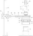
Translated fromKorean도 1은 본 발명의 일실시예에 따른 디스플레이 패널 검사장치의 정면도이다.1 is a front view of a display panel inspection apparatus according to an embodiment of the present invention.
도 2는 본 발명의 일실시예에 따른 디스플레이 패널 검사장치의 구성을 도시한 블록도이다.2 is a block diagram illustrating a configuration of a display panel inspecting apparatus according to an exemplary embodiment.
도 3은 도1 및 도2에 도시된 장치에서 제1실시예에 따른 제1영상을 얻는 과정을 도시한 도면이다.3 is a diagram illustrating a process of obtaining a first image according to a first embodiment in the apparatus shown in FIGS. 1 and 2.
도 4는 도 1및 도2에 도시된 장치에서 제1 및 제2실시예에 따른 제2영상을 얻는 과정을 도시한 도면이다.4 is a diagram illustrating a process of obtaining second images according to the first and second embodiments in the apparatus shown in FIGS. 1 and 2.
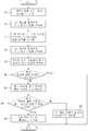
도 5는 본 발명의 제1실시예에 따른 디스플레이 패널의 검사방법을 도시한 흐름도이다.5 is a flowchart illustrating a method of inspecting a display panel according to a first embodiment of the present invention.
도 6은 도1 및 도2에 도시된 장치에서 제2실시예에 따른 제1임시영상을 얻는 과정을 도시한 도면이다.FIG. 6 is a diagram illustrating a process of obtaining a first temporary image according to a second embodiment in the apparatus shown in FIGS. 1 and 2.
도 7은 본 발명의 제2실시예에 따른 디스플레이 패널의 검사방법을 도시한 흐름도이다. 7 is a flowchart illustrating a method of inspecting a display panel according to a second embodiment of the present invention.
*도면의 주요 기능에 대한 부호의 설명** Description of the symbols for the main functions of the drawings *
10:스테이지 11:백라이트10: Stage 11: Back light
15:LCD패널 20:조명장치15: LCD panel 20: Lighting device
21:상부조명 22:경사조명21: Upper lighting 22: Inclined lighting
40:고배율 카메라 50:카메라 지지부40: high power camera 50: camera support
60:제어부 63:패턴생성기60: control unit 63: pattern generator
본 발명은 디스플레이 패널의 검사장치 및 검사방법에 관한 것으로, 더욱 상세하게는 디스플레이 패널 자체의 불량을 정확하게 검지할 수 있는 디스플레이 패널의 검사장치 및 검사방법에 관한 것이다.The present invention relates to an inspection apparatus and an inspection method of a display panel, and more particularly, to an inspection apparatus and an inspection method of a display panel capable of accurately detecting a defect of the display panel itself.
일반적으로, 디스플레이 패널은 데이터를 시각적으로 표시하는 표시장치로 LCD(liquid crystal display:액정 디스플레이-이하에서 LCD라 한다), PDP(plasma display panel:플라즈마 디스플레이 패널)등이 있다.In general, a display panel is a display device for visually displaying data, such as an LCD (liquid crystal display) or a plasma display panel (PDP).
이 중에서 LCD 패널은 액체와 고체의 중간적인 특징을 가지는 액정의 전기광학적인 성질을 이용한 표시장치이다. 즉, LCD패널은 백라이트에서 발생하는 빛의 양을 내부 액정의 움직임을 통해 조절하여 특정한 패턴을 화면에 표시한다.Among them, the LCD panel is a display device using the electro-optical properties of the liquid crystal having an intermediate characteristic between liquid and solid. That is, the LCD panel displays a specific pattern on the screen by adjusting the amount of light generated from the backlight through the movement of the internal liquid crystal.
이러한 LCD패널은 제조과정에서 침투한 이물이나 패널 자체의 전기적인 결함등에 의해 패턴이 제대로 생성되지 않는 불량이 있을 수 있는 바 종래에도 LCD패널의 불량을 검지하기 위한 각종 검사장치들이 개발되어 왔다.The LCD panel may have a defect in which a pattern is not properly generated due to foreign matter penetrated during the manufacturing process or an electrical defect of the panel itself, and various inspection apparatuses for detecting a defect of the LCD panel have been developed.
종래 LCD패널의 검사장치는 통상 백라이트와, 검사를 위해 미리 설정된 패턴 을 LCD패널에 인가하는 패턴 생성기와, LCD패널을 촬영하여 영상을 얻는 카메라와, 검사장치의 전체적인 동작을 제어하는 마이컴으로 구성된다.Conventional LCD panel inspection apparatus usually includes a backlight, a pattern generator for applying a predetermined pattern to the LCD panel for inspection, a camera for capturing an image by photographing the LCD panel, and a microcomputer for controlling the overall operation of the inspection apparatus. .
이와 같은 종래의 LCD패널의 검사장치는 LCD패널의 불량검사를 위해 검사대상인 LCD패널에 시험용 패턴을 인가하고 백라이트를 온 시킨다. 그리고 카메라를 통해 LCD패널을 촬영하여 LCD패널에 대한 영상을 얻는다. LCD패널에 대한 영상이 얻어지면 마이컴은 얻어진 영상을 분석하여 LCD패널의 불량여부를 판단한다. LCD패널의 검사에서 나타나는 불량의 형태로는 하이불량과 오프불량 등이 있을 수 있는 데 하이불량은 블랙패턴을 인가한 경우 전부 검은색이 표시되어야 하나 일부 지점에서 빛이 새어나오는 경우이고 오프불량은 화이트패턴을 인가한 경우 빛이 나오지 않고 어둡게 되는 부분이 있는 경우이다.The inspection apparatus of the conventional LCD panel applies a test pattern to the LCD panel to be inspected and turns on the backlight for the defective inspection of the LCD panel. And the LCD panel is taken by the camera to obtain an image of the LCD panel. When an image of the LCD panel is obtained, the microcomputer analyzes the obtained image to determine whether the LCD panel is defective. The types of defects that appear in the inspection of the LCD panel may include high defects and off defects. High defects should be displayed in black when the black pattern is applied, but light leaks from some points. When white pattern is applied, there is a part that becomes dark without light.
그런데 LCD패널의 검사시에 LCD패널 자체의 불량외에 외부요인에 의해 마치 LCD패널의 불량인 것처럼 표시되는 경우가 있다. 즉, LCD패널의 검사를 위해 백라이트를 온 시키면 제조과정에서 LCD패널을 보호하기 위해 부착한 보호필름의 표면 스크래치(scratch)나 보호필름 표면에 부착된 먼지등이 LCD패널을 투과한 빛의 산란을 일으키게 하고 이러한 상태에서 LCD패널을 촬영하여 얻은 영상에서는 먼지나 표면 스크래치가 있는 부분이 LCD패널 자체가 불량인 경우와 동일한 형태로 표시된다.However, when the LCD panel is inspected, external factors other than the LCD panel itself may be displayed as if the LCD panel is defective. That is, when the backlight is turned on for the inspection of the LCD panel, the surface scratch of the protective film attached to protect the LCD panel during the manufacturing process or the dust attached to the surface of the protective film prevents scattering of light transmitted through the LCD panel. In the image obtained by photographing the LCD panel in such a state, a part with dust or surface scratches is displayed in the same form as when the LCD panel itself is defective.
따라서 종래의 LCD패널의 검사장치 및 검사방법은 LCD패널 자체의 불량을 먼지나 표면 스크래치 등과 구분하지 못하여 LCD패널 검사에 있어 오판정을 유발할 수 있는 문제점이 있었다.Therefore, the inspection apparatus and inspection method of the conventional LCD panel can not distinguish the defect of the LCD panel itself, such as dust or surface scratches, there was a problem that may cause a misjudgment in the LCD panel inspection.
본 발명은 전술한 문제점을 해결하기 위한 것으로, 본 발명의 목적은 디스플레이 패널 자체의 불량을 정확하게 검지해 낼 수 있는 디스플레이 패널의 검사장치 및 검사방법을 제공함에 있다.The present invention is to solve the above problems, an object of the present invention to provide an inspection apparatus and inspection method of the display panel that can accurately detect the defect of the display panel itself.
전술한 목적을 달성하기 위한 본 발명은 디스플레이 패널의 표면에 빛을 조사하고 상기 디스플레이 패널을 촬영하여 제1영상을 얻는 단계와, 상기 디스플레이 패널에 패턴을 인가한 상태로 상기 디스플레이 패널에 빛을 조사하고 상기 디스플레이 패널을 촬영하여 제2영상을 얻는 단계와, 상기 제1영상과 상기 제2영상을 서로 비교하여 상기 디스플레이 패널의 불량여부를 판단하는 단계를 포함한다.The present invention for achieving the above object is to irradiate light on the surface of the display panel and to obtain a first image by photographing the display panel, and to irradiate light to the display panel while applying a pattern to the display panel Photographing the display panel to obtain a second image; and comparing the first image and the second image with each other to determine whether the display panel is defective.
또한 상기 제1영상과 상기 제2영상을 서로 비교하여 상기 디스플레이 패널의 불량여부를 판단하는 단계는 상기 제1 및 제2영상에서 각각 불량지점을 확인하는 단계와, 상기 제2영상에서 불량지점이 확인되면 상기 제1영상 및 제2영상의 불량지점을 비교하는 단계와, 상기 제1영상의 불량지점과 상기 제2영상의 불량지점 위치가 다른 경우 상기 디스플레이 패널의 불량지점인 것으로 결정하는 단계를 포함하는 것을 특징으로 한다.In addition, comparing the first image and the second image with each other and determining whether the display panel is defective may be performed by identifying each of the defective points in the first and second images, and the defective points in the second image. If it is confirmed, comparing the defective points of the first image and the second image, and determining that the defective point of the first image and the defective point of the second image are different from each other. It is characterized by including.
또한 상기 제2영상에서 불량지점이 확인되지 않으면 상기 디스플레이 패널의 불량이 없는 것으로 결정하는 것을 특징으로 한다.In addition, if a defect point is not confirmed in the second image, the display panel may be determined to have no defect.
또한 상기 제1영상의 불량지점과 상기 제2영상의 불량지점 위치가 같은 경우 상기 디스플레이 패널의 불량지점이 아닌 것으로 결정하는 것을 특징으로 한다.In addition, when the bad point of the first image and the bad point position of the second image is the same, it is determined that it is not a bad point of the display panel.
또한 상기 제1영상은 상기 디스플레이 패널의 표면에 빛을 조사하는 조명장치를 온 시키고 상기 디스플레이 패널의 후면에 빛을 조사하는 백라이트를 오프시킨 상태에서 상기 디스플레이 패널에 패턴을 인가하지 않고 상기 디스플레이 패널을 촬영하여 얻는 것을 특징으로 한다.In addition, the first image is a display panel without applying a pattern to the display panel while the illumination device for illuminating the surface of the display panel is turned on and the backlight for irradiating the light on the back of the display panel is turned off It is characterized by obtaining by shooting.
상기 제1영상은 상기 디스플레이 패널의 표면에 빛을 조사하는 조명장치를 온 시키고 상기 디스플레이 패널의 후면에 빛을 조사하는 백라이트를 온시킨 상태에서 상기 디스플레이 패널에 블랙패턴을 인가하고 상기 디스플레이 패널을 촬영하여 얻는 것을 특징으로 한다.The first image applies a black pattern to the display panel while photographing the display panel while turning on a lighting device for irradiating light to the surface of the display panel and turning on a backlight for irradiating light to the rear of the display panel. It is characterized by obtained by.
또한 상기 제2영상은 상기 디스플레이 패널의 표면에 빛을 조사하는 조명장치를 오프 시키고 상기 디스플레이 패널의 후면에 빛을 조사하는 백라이트를 온 시킨 상태에서 상기 디스플레이 패널을 촬영하여 얻는 것을 특징으로 한다.The second image may be obtained by photographing the display panel while turning off a lighting device for irradiating light to the surface of the display panel and turning on a backlight for irradiating light to a rear surface of the display panel.
또한 상기 디스플레이 패널은 엘시디 패널인 것을 특징으로 한다.In addition, the display panel is characterized in that the LCD panel.
또한 보호막을 갖는 디스플레이 패널의 검사방법에 있어서, 상기 보호막에 빛을 조사하고 상기 보호막을 촬영하여 제1영상을 얻는 단계와, 상기 디스플레이 패널에 패턴을 인가한 상태로 상기 디스플레이 패널에 빛을 조사하고 상기 패턴과 상기 보호막을 촬영하여 제2영상을 얻는 단계와, 상기 제1영상과 상기 제2영상을 서로 비교하여 상기 디스플레이 패널의 불량여부를 판단하는 단계를 포함하는 것을 특징으로 한다.The method of inspecting a display panel having a protective film, the method comprising: irradiating light to the protective film and photographing the protective film to obtain a first image; and irradiating light to the display panel while applying a pattern to the display panel. Photographing the pattern and the passivation layer to obtain a second image; and comparing the first image and the second image with each other to determine whether the display panel is defective.
또한 디스플레이 패널의 표면에 빛을 조사하는 제1조명장치와, 상기 디스플레이 패널의 후면에 빛을 조사하는 제2조명장치와, 상기 제1조명장치와 연계하여 상기 디스플레이 패널을 촬영함으로써 제1영상을 얻고, 상기 디스플레이 패널에 패턴을 인가하고 상기 제2조명장치와 연계하여 상기 디스플레이 패널을 촬영함으로써 제2영상을 얻는 촬영장치와, 상기 촬영장치에서 얻은 제1 및 제2영상을 전달받고 상기 제1 및 제2영상을 비교하여 상기 디스플레이 패널의 불량여부를 판단하는 제어부를 포함하는 것을 특징으로 한다.In addition, a first illumination device for irradiating light to the surface of the display panel, a second illumination device for irradiating light to the back of the display panel, and in conjunction with the first illumination device to capture the first image by photographing the display panel And a photographing apparatus which obtains a second image by applying a pattern to the display panel and photographing the display panel in association with the second lighting apparatus, and receiving first and second images obtained by the photographing apparatus. And a controller for comparing the second image to determine whether the display panel is defective.
또한 상기 불량여부는 상기 제1영상에서 확인된 불량지점과 상기 제2영상에서 확인된 불량지점이 일치하는지 여부로 결정하는 것을 특징으로 한다.The defect may be determined by determining whether or not the defect point identified in the first image and the defect point identified in the second image coincide with each other.
또한 상기 제1조명장치의 내부에는 다양한 조사각도를 갖도록 다수의 램프 또는 엘이디가 다양한 위치에 배열되는 것을 특징으로 한다.In addition, the inside of the first lighting device is characterized in that a plurality of lamps or LEDs are arranged in various positions to have a variety of irradiation angles.
또한 상기 디스플레이 패널은 엘시디 패널인 것을 특징으로 한다.In addition, the display panel is characterized in that the LCD panel.
또한 보호막을 갖는 디스플레이 패널의 검사장치에 있어서, 상기 보호막에 빛을 조사하는 제1조명장치와, 상기 디스플레이 패널의 후면에 빛을 조사하는 제2조명장치와, 상기 제1조명장치와 연계하여 상기 보호막을 촬영함으로써 제1영상을 얻고, 상기 제2조명장치와 연계하여 상기 디스플레이 패널의 패턴과 상기 보호막을 촬영함으로써 제2영상을 얻는 촬영장치와, 상기 촬영장치에서 얻은 제1 및 제2영상을 전달받고 상기 제1 및 제2영상을 비교하여 상기 디스플레이 패널의 불량여부를 판단하는 제어부를 포함하는 것을 특징으로 한다.A display panel inspection apparatus having a protective film, comprising: a first lighting device for irradiating light to the protective film, a second lighting device for irradiating light to a rear surface of the display panel, and the first lighting device in association with the first lighting device A photographing apparatus which obtains a first image by photographing a protective film, obtains a second image by photographing a pattern of the display panel and the protective film in association with the second lighting apparatus, and a first and second image obtained by the photographing apparatus. And a controller configured to determine whether the display panel is defective by comparing the first and second images.
이하에서는 본 발명의 바람직한 실시예를 본 도면을 참조하여 상세하게 설명하도록 한다.Hereinafter, preferred embodiments of the present invention will be described in detail with reference to the drawings.
도 1에 도시된 바와 같이 본 발명의 일실시예에 따른 디스플레이 패널의 검 사장치는 검사대상인 LCD패널(15)을 위치시키기 위한 스테이지(10)와, LCD패널(15)의 상부에서 LCD패널(15)에 빛을 조사하고 조명 지지부(30)에 의해 지지되는 조명장치(20)와, 전면조명(20)의 상부에서 LCD패널(15)을 촬영하고 카메라 지지부(50)에 설치되는 고배율 카메라(40)를 구비한다. As shown in FIG. 1, an inspection apparatus for a display panel according to an exemplary embodiment of the present invention includes a
조명 지지부(30)는 상하방향으로 길게 형성된 제1승강레일(31)과, 제1승강레일(31)에 이동가능하도록 결합되어 상하로 이동하는 제1승강부재(32)와, 제1승강부재(32)에 설치되어 제1승강부재(32)를 고정시키는 고정레버(33)를 구비한다. 제1승강부재(32)의 측면에는 수평이동레일(34)이 마련되고, 수평이동레일(34)에는 수평이동 슬라이더(35)가 가로방향으로 이동이 가능하도록 설치된다. 수평이동 슬라이더(35)의 하면에는 조명장치(20)의 외부상면이 결합되며, 수평이동 슬라이더(35)를 이동시켜 조명장치(20)의 가로방향 위치를 조절할 수 있다. 수평이동레일(34)의 상면에는 수평이동 슬라이더(35)를 고정시키기 위한 제2고정레버(36)가 마련된다.The
카메라 지지부(50)는 제2승강레일(51)과, 제2승강레일(51)에 상하로 이동이 가능하도록 결합된 제2승강부재(52)를 구비한다. 제2승강부재(52)의 전방에는 브라켓(53)에 의해 고배율 카메라(40)가 부착되며 이에 따라 제2승강부재(52)를 이동시킴으로써 고배율 카메라(40)의 상하위치를 조절할 수 있다.The
스테이지(10)의 하부에는 LCD패널(15)에 빛을 조사해주는 백라이트(11)가 설치되고, 백라이트(11)는 백라이트 지지대(12)에 의해 지지된다. 여기에서 스테이지(10)는 백라이트(11)로부터 상부로 조사된 빛을 통과시킬 수 있는 재질로 구성됨이 바람직하다. 그리고 스테이지(10)와 백라이트(11)의 사이에는 후술할 패 턴 생성기(도2의 63)에서 전송된 패턴신호를 LCD패널(15)에 인가하는 프루빙 장치(13)가 마련된다. A
도 2에 도시된 바와 같이 본 발명의 일실시예에 따른 디스플레이 패널의 검사장치는 고배율 카메라(40)를 구동하는 카메라 구동부(65)와, 조명장치(20)를 구동하는 조명장치 구동부(61)와, 백라이트(11)를 구동하는 백라이트 구동부(62)와, LCD패널(15)에 인가할 패턴신호를 생성하는 패턴 생성기(63)를 구비한다.As shown in FIG. 2, an inspection apparatus for a display panel according to an exemplary embodiment includes a
또한, 본 발명의 일실시예에 따른 디스플레이 패널의 검사장치는 고배율 카메라(40)에서 전송된 영상신호를 처리하여 영상을 복원하는 영상처리부(67)와, 영상처리부(67)에서 처리된 영상을 비교하여 LCD패널(15) 자체의 불량인지 여부를 판단하는 제2제어부(66)를 구비한다. 이를 위해 영상처리부(67)에는 영상신호를 복원하기 위한 데이터가 미리 저장되어 있다. 제2제어부(66)는 LCD패널(15)을 촬영하여 얻은 복수의 영상을 각각 복수의 셀로 나누고, 복수의 영상에서 동일한 지점에 해당하는 특정셀의 영상을 서로 비교하여 영상의 상호 일치여부를 판단한다.In addition, the inspection apparatus of the display panel according to an embodiment of the present invention is an
또한, 본 발명의 일실시예에 따른 디스플레이 패널의 검사장치는 영상처리부(67)에서 복원된 영상을 표시하는 표시부(64)와, 제어명령을 입력하기 위한 입력부(68)와, 검사장치의 전체적인 동작을 제어하기 위한 제1제어부(60)를 구비한다.In addition, the inspection apparatus of the display panel according to an embodiment of the present invention includes a
도3 내지 도5를 참조하여 본 발명의 제1실시예에 따른 디스플레이 패널의 검사방법을 설명한다. 본 발명의 제1실시예에 따른 디스플레이 패널의 검사방법으로 검사할 수 있는 LCD패널(15)은 제조과정에서 LCD패널(15)을 보호하기 위한 보호필 름(18)이 LCD패널(15)의 표면에 부착된다.An inspection method of a display panel according to a first embodiment of the present invention will be described with reference to FIGS.
그리고 본 발명의 제1실시예에 따른 디스플레이 패널의 검사장치에 포함되는 조명장치(20)는 도3에 도시된 바와 같이 조명장치(20)의 내부 상면에 설치된 상부조명(21)과, 조명장치(20)의 내부 경사면에 설치된 경사조명(22)을 구비한다. 상부조명(21)은 다수의 램프 또는 LED(light emitted diode:발광 다이오우드) 등의 발광소자가 등간격 환상으로 배치되고, 경사조명(22)은 다수의 램프 또는 LED 등의 발광소자가 등간격 환상 다단으로 배열된다. 이와 같이 다수의 발광소자가 위치를 달리하여 규칙적으로 배열됨으로써 다수의 발광소자를 온 시킬 경우 각 발광소자에서 LCD패널(15)에 도달되는 빛은 다양한 조사각도를 가지게 된다. 조명장치(20)의 상부에는 고배율 카메라(40)에서 LCD패널(15)을 촬영할 수 있도록 촬영공(23)이 형성된다. 이러한 조명장치(20)의 형태와 설치위치는 다양하게 할 수 있다. 예를 들어 LCD패널(15)보다 낮은 위치에 발광소자를 설치하여 상방으로 빛을 조사하고 조사된 빛을 LCD패널(15) 상부에 설치된 반사판에서 반사시켜 LCD패널(15)로 보낼 수 있다.In addition, the
도3 및 도5에 도시된 바와 같이 먼저 제어부(60)는 조명장치 구동부(61)와 백라이트 구동부(62)에 제어신호를 전송하여 조명장치(20)를 온 시키고, 백라이트(11)를 오프시킨다(70). 그리고 LCD패널(15)에 패턴은 인가하지 않는다. 도3에서 16은 보호필름위에 부착된 먼지이다. 백라이트(11)가 오프되어 있으므로 LCD패널(15)은 어둡게 보이게 되고, 조명장치(20)에서 다양한 각도로 조사된 빛에 의해 보호필름(18) 표면에 부착된 먼지(16)나 표면 스크래치(미도시)는 밝게 빛나 게 된다. 이러한 상태에서 제어부(60)는 고배율 카메라(40)를 통해 LCD패널(15)을 촬영하는데 촬영된 영상(41)에서는 먼지(16)나 표면 스크래치가 있는 지점(X지점)이 LCD패널(15) 자체의 불량인 경우와 동일한 형태로 표시된다. 고배율 카메라(40)에서 촬영된 영상(41)은 제1영상신호로 변환되어 제어부(60)로 전송된다(72). 3 and 5, first, the
다음으로 도4 및 도5에 도시된 바와 같이 제어부(60)는 조명장치 구동부(61)와 백라이트 구동부(62)에 제어신호를 전송하여 백라이트(11)를 온 시키고, 조명장치(20)를 오프시킨다(74). 또한, 패턴 생성기(63)에 제어신호를 보내 LCD패널(15)에 패턴(예를 들면 블랙패턴)을 인가하도록 한다. 도 4에서 17은 LCD패널 자체의 불량을 나타낸 것이다. LCD패널(15)에 패턴이 인가되고 백라이트(11)가 온되었으므로 LCD패널(15)에는 미리 설정된 패턴이 표시된다. 그러나 LCD패널(15)자체의 불량이 있는 지점(Y지점)은 설정된 패턴이 형성되지 않고, 보호필름(18)의 먼지(16)나 표면 스크래치도 LCD패널(15)을 통과한 빛을 산란시킨다. 이러한 상태에서 제어부(60)는 고배율 카메라(40)를 통해 LCD패널(15)을 촬영하는데 촬영된 LCD패널(15)의 영상에서는 LCD패널(15) 자체의 불량인 지점(Y지점)과 먼지(16)나 표면 스크래치가 있는 지점(X지점)이 모두 LCD패널(15)의 불량지점인 것처럼 표시된다. 촬영된 영상은 제2영상신호로 변환되어 제1제어부(60)로 전송된다(76).Next, as shown in FIGS. 4 and 5, the
제1 및 제2영상신호가 전송되면 제1제어부(60)는 고배율 카메라(40)에서 전송된 제1영상신호와 제2영상신호를 영상처리부(67)에서 복원하도록 하고(78), 영상처리부(67)에서 복원이 완료되면 복원된 제1영상(41)과 제2영상(42)을 제2제어부(66)로 전송한다. 제1영상(41) 및 제2영상(42)이 전송되면 제2제어부(66) 는 먼저 제2영상(42)에 불량지점이 있는 지를 판단한다(80). 제2영상(42)에 불량지점이 있는 지는 제2영상(42)이 미리 설정된 패턴의 영상과 동일한 지 여부로 결정한다. 만약 제2영상(42)에 불량지점이 없다면 LCD패널(15) 자체의 불량은 없는 것으로 보아 사이클을 종료한다. 그러나 제2영상(42)에 불량지점이 있는 것으로 판단되면 제2제어부(66)는 제1영상(41)과 제2영상(42)을 다수의 셀로 나누어 비교한 후(82) 제2영상(42)의 불량지점이 제1영상(41)의 불량지점과 일치하는지 판단한다(84).When the first and second image signals are transmitted, the
만약 제1영상(41)의 불량지점과 제2영상(42)의 불량지점이 일치한다면 제2영상(42)에 표시된 불량은 제1영상(41)에서도 표시된 불량이므로 LCD패널(15) 자체의 불량이 아니고, 보호필름(18)의 먼지(16)나 표면 스크래치 등으로 본다(88). 본 발명의 제1실시예에서는 제1영상(41)과 제2영상(42)에서 각각 X지점에 불량이 있는 것으로 확인되어 X지점은 LCD패널(15) 자체의 불량이 아닌 것으로 결정할 수 있다.If the defective point of the
그러나 제1영상(41)의 불량지점과 제2영상(42)의 불량지점이 일치하지 않는다면 제2영상(42)에 표시된 불량은 LCD패널(15) 자체의 불량인 것으로 결정한다(86). 이 때 복수의 셀로 분할된 영상에서 불량인 지점의 위치를 알 수 있으므로 결국 LCD패널(15)에서 어떤 부분(또는 픽셀)에 불량이 발생했는지도 파악할 수 있게 된다. 본 발명의 제1실시예에서는 제2영상(42)에서 불량지점인 Y지점이 제1영상(41)에서는 나타나지 않았으므로 Y지점은 LCD패널(15) 자체의 불량지점인 것으로 결정할 수 있게 된다.However, if the defect point of the
도4 및 도6 내지 7을 참조하여 본 발명의 제2실시예에 따른 디스플레이 패 널의 검사방법을 설명한다.4 and 6 to 7, a method of inspecting a display panel according to a second embodiment of the present invention will be described.
도6 및 도7에 도시된 바와 같이 먼저 제어부(60)는 조명장치 구동부(61)와 백라이트 구동부(62)에 제어신호를 전송하여 조명장치(20)를 온 시키고, 백라이트(11)를 온시킨다(90). 그리고 LCD패널(15)의 바탕이 검은 색이 되는 블랙패턴을 인가한다. 도6에서 16은 보호필름(18)위에 부착된 먼지이고, 17은 LCD패널(15) 자체의 불량이다. 백라이트(11)가 온 되어 있더라도 LCD패널(15)에 블랙패턴이 인가된 상태이므로 LCD패널(15)은 어둡게 보이게 되고, 조명장치(20)에서 다양한 각도로 조사된 빛에 의해 보호필름(18) 표면에 부착된 먼지(16)나 표면 스크래치(미도시)는 밝게 빛나게 된다. 이러한 상태에서 제어부(60)는 고배율 카메라(40)를 통해 LCD패널(15)을 촬영하는데 촬영된 영상(41)에서는 먼지(16)나 표면 스크래치가 있는 지점(X지점)과 LCD패널(15) 자체의 불량지점(Y지점)이 모두 표시된다. 고배율 카메라(40)에서 촬영된 영상(43)은 제1임시영상신호로 변환되어 제어부(60)로 전송된다(92). 6 and 7, first, the
제2영상신호를 얻는 과정(94 내지 96)은 제1실시예와 동일하게 적용된다.The
제1 임시영상신호 및 제2영상신호가 전송되면 제1제어부(60)는 제1임시영상신호와 제2영상신호를 영상처리부(67)에서 복원하도록 하고(98), 영상처리부(67)에서 복원이 완료되면 복원된 제1임시영상(43)과 제2영상(42)을 제2제어부(66)로 전송한다. 제1임시영상(43) 및 제2영상(42)이 전송되면 제2제어부(66)는 먼저 제2영상(42)에 불량지점이 있는 지를 판단한다(100). 제2영상(42)에 불량지점이 있는 지는 제2영상(42)이 미리 설정된 패턴의 영상과 동일한 지 여부로 결정한다.When the first temporary video signal and the second video signal are transmitted, the
만약 제2영상(42)에 불량지점이 없다면 LCD패널(15) 자체의 불량은 없는 것으로 보아 사이클을 종료한다. 그러나 제2영상(42)에 불량지점이 있는 것으로 판단되면 제2제어부(66)은 제1임시영상(43)과 제2영상(42)을 서로 비교하여 제1영상(41)을 얻는다(102). 제1영상(41)을 얻기 위해 제2제어부(66)는 제1임시영상(43)과 제2영상(42)을 다수의 셀로 나눈 후 동일한 위치에 있는 제1임시영상(43)의 셀과 제2영상(42)의 셀의 차이를 비교한다. 제1임시영상(43)과 제2영상(42)은 모두 패턴이 인가된 상태에서 촬영되었으므로 LCD패널(15) 자체의 불량지점(Y지점)은 제1임시영상(43)과 제2영상(42)에서 거의 동일한 형태와 밝기로 표시될 것이다.If there is no defective point in the
그러나 먼지(16) 또는 표면스크래치 등이 있는 지점(X지점)은 조명장치(20)가 오프된 상태에서 촬영된 제2영상(42) 보다 조명장치(20)가 온된 상태에서 촬영된 제1임시영상(43)에서 더 밝게 표시된다. 따라서 제1임시영상(43) 및 제2영상(42)에서 모두 불량지점인 것처럼 표시되지만 제1임시영상(43)과 제2영상(42)의 밝기의 차이가 있는 불량지점은 먼지(16) 또는 표면 스크래치 등이 있는 지점으로 보아 LCD패널(15) 자체의 불량이 아닌 것으로 볼 수 있다.However, the point where the
제2제어부(66)는 이와 같이 제1임시영상(43)과 제2영상(42)에서 밝기의 차이가 있는 불량지점은 존속시키고, 밝기나 형태의 차이가 없는 불량지점은 제외시켜 제1영상(41)을 얻는다. 결국 제1영상(41)에서는 먼지(16)나 표면 스크래치가 있는 지점만이 불량지점인 것 처럼 표시된다.As such, the
제1영상(41)이 얻어지면 제2제어부(66)는 제1영상(41)과 제2영상(42)을 다수의 셀로 나누어 비교한 후(104) 제2영상(42)의 불량지점이 제1영상(41)의 불량지점 과 일치하는지 판단한다(106).When the
만약 제1영상(41)의 불량지점과 제2영상(42)의 불량지점이 일치한다면 제2영상(42)에 표시된 불량은 제1영상(41)에서도 표시된 불량이므로 LCD패널(15) 자체의 불량이 아니고, 보호필름(18)의 먼지(16)나 표면 스크래치 등으로 본다(110). 본 발명의 제2실시예에서는 제1영상(41)과 제2영상(42)에서 각각 X지점에 불량이 있는 것으로 확인되어 X지점은 LCD패널(15) 자체의 불량이 아닌 것으로 결정할 수 있다.If the defective point of the
그러나 제1영상(41)의 불량지점과 제2영상(42)의 불량지점이 일치하지 않는다면 제2영상(42)에 표시된 불량은 LCD패널(15) 자체의 불량인 것으로 결정한다(108). 이 때 복수의 셀로 분할된 영상에서 불량인 지점의 위치를 알 수 있으므로 결국 LCD패널(15)에서 어떤 부분(또는 픽셀)에 불량이 발생했는지도 파악할 수 있게 된다. 본 발명의 제2실시예에서는 제2영상(42)에서 불량지점인 Y지점이 제1영상(41)에서는 나타나지 않았으므로 Y지점은 LCD패널(15) 자체의 불량지점인 것으로 결정할 수 있게 된다.However, if the defect point of the
이상에서 상세히 설명한 바와 같이, 본 발명은 디스플레이 패널 자체의 불량여부를 정확하게 판단할 수 있어 디스플레이 패널 검사시 오판정을 방지할 수 있다.As described in detail above, the present invention can accurately determine whether or not the display panel itself is defective can prevent the misjudgment during the display panel inspection.
Claims (14)
Translated fromKoreanPriority Applications (4)
| Application Number | Priority Date | Filing Date | Title |
|---|---|---|---|
| KR1020040006132AKR100955486B1 (en) | 2004-01-30 | 2004-01-30 | Display device inspection device and inspection method |
| US10/938,644US7166856B2 (en) | 2004-01-30 | 2004-09-13 | Apparatus and method to inspect display panels |
| CNB200410080449XACN100480690C (en) | 2004-01-30 | 2004-10-10 | Apparatus and method for inspecting display panels |
| JP2004312970AJP4264407B2 (en) | 2004-01-30 | 2004-10-27 | Display panel inspection apparatus and inspection method |
Applications Claiming Priority (1)
| Application Number | Priority Date | Filing Date | Title |
|---|---|---|---|
| KR1020040006132AKR100955486B1 (en) | 2004-01-30 | 2004-01-30 | Display device inspection device and inspection method |
Publications (2)
| Publication Number | Publication Date |
|---|---|
| KR20050078034A KR20050078034A (en) | 2005-08-04 |
| KR100955486B1true KR100955486B1 (en) | 2010-04-30 |
Family
ID=34806051
Family Applications (1)
| Application Number | Title | Priority Date | Filing Date |
|---|---|---|---|
| KR1020040006132AExpired - Fee RelatedKR100955486B1 (en) | 2004-01-30 | 2004-01-30 | Display device inspection device and inspection method |
Country Status (4)
| Country | Link |
|---|---|
| US (1) | US7166856B2 (en) |
| JP (1) | JP4264407B2 (en) |
| KR (1) | KR100955486B1 (en) |
| CN (1) | CN100480690C (en) |
Cited By (1)
| Publication number | Priority date | Publication date | Assignee | Title |
|---|---|---|---|---|
| KR20160095683A (en)* | 2015-02-03 | 2016-08-12 | 삼성디스플레이 주식회사 | Surface defect inspecting apparatus and the inspecting method using the same |
Families Citing this family (80)
| Publication number | Priority date | Publication date | Assignee | Title |
|---|---|---|---|---|
| KR101034923B1 (en)* | 2004-05-31 | 2011-05-17 | 엘지디스플레이 주식회사 | Auto probe inspection equipment and inspection method using the same |
| KR20060044032A (en)* | 2004-11-11 | 2006-05-16 | 삼성전자주식회사 | Inspection device for display panel and inspection method |
| WO2007047685A2 (en)* | 2005-10-17 | 2007-04-26 | I2Ic Corporation | Combined video display and camera system |
| KR101201322B1 (en)* | 2005-12-29 | 2012-11-14 | 엘지디스플레이 주식회사 | Apparatus for Testing flat panel display device and method thereof |
| JP4909672B2 (en)* | 2006-08-08 | 2012-04-04 | 株式会社日本マイクロニクス | Liquid crystal panel inspection method and apparatus |
| US7639353B2 (en)* | 2006-08-09 | 2009-12-29 | Research In Motion Limited | Method, device and system for evaluating a lens for an electronic device |
| JP4960161B2 (en)* | 2006-10-11 | 2012-06-27 | 日東電工株式会社 | Inspection data processing apparatus and inspection data processing method |
| US20100109986A1 (en)* | 2007-03-28 | 2010-05-06 | Pioneer Corporation | Display device, display panel, display inspection method, and display panel manufacturing method |
| KR101068364B1 (en)* | 2007-07-11 | 2011-09-28 | 엘지디스플레이 주식회사 | LCD Display Inspection Equipment and Inspection Method |
| EP2116890A1 (en)* | 2008-05-09 | 2009-11-11 | Shun-Kun Kuo | Testing apparatus for fixing and testing a LCD panel |
| US20130144797A1 (en)* | 2008-10-02 | 2013-06-06 | ecoATM, Inc. | Method And Apparatus For Recycling Electronic Devices |
| EP2335337B1 (en) | 2008-10-02 | 2020-03-11 | ecoATM, LLC | Secondary market and vending system for devices |
| US11010841B2 (en) | 2008-10-02 | 2021-05-18 | Ecoatm, Llc | Kiosk for recycling electronic devices |
| US10853873B2 (en) | 2008-10-02 | 2020-12-01 | Ecoatm, Llc | Kiosks for evaluating and purchasing used electronic devices and related technology |
| US9881284B2 (en) | 2008-10-02 | 2018-01-30 | ecoATM, Inc. | Mini-kiosk for recycling electronic devices |
| US8200533B2 (en)* | 2008-10-02 | 2012-06-12 | ecoATM, Inc. | Apparatus and method for recycling mobile phones |
| US7881965B2 (en) | 2008-10-02 | 2011-02-01 | ecoATM, Inc. | Secondary market and vending system for devices |
| KR101292570B1 (en)* | 2008-12-31 | 2013-08-12 | 엘지디스플레이 주식회사 | System for testing distortion of liquid crystal display device |
| CN101592812B (en)* | 2009-06-23 | 2012-05-23 | 友达光电(苏州)有限公司 | Display panel and pixel defect check method thereof |
| JP5549203B2 (en)* | 2009-12-01 | 2014-07-16 | セイコーエプソン株式会社 | Optical position detection device, hand device, and touch panel |
| JP5549204B2 (en)* | 2009-12-01 | 2014-07-16 | セイコーエプソン株式会社 | Optical position detection device, hand device, and touch panel |
| US20120133761A1 (en)* | 2010-11-30 | 2012-05-31 | Angstrom, Inc. | Uneven area inspection system |
| DE202012013245U1 (en) | 2011-04-06 | 2015-09-14 | ecoATM, Inc. | Automat for recycling electronic devices |
| JP5196337B1 (en)* | 2011-04-28 | 2013-05-15 | 株式会社湯山製作所 | Drug inspection device and drug packaging device |
| KR101306289B1 (en)* | 2011-09-15 | 2013-09-09 | (주) 인텍플러스 | Method of inspecting plat panel |
| CN102788799A (en)* | 2012-07-27 | 2012-11-21 | 昆山微容电子企业有限公司 | Automatic appearance screening device |
| JP6381865B2 (en)* | 2012-08-24 | 2018-08-29 | 内外化成株式会社 | Inspection apparatus and inspection method |
| KR20140091916A (en)* | 2013-01-14 | 2014-07-23 | 삼성디스플레이 주식회사 | Inspection Method For Display Panel |
| CN103177983B (en)* | 2013-03-01 | 2016-09-28 | 日月光半导体制造股份有限公司 | Detection device and method |
| JP6104016B2 (en)* | 2013-04-01 | 2017-03-29 | 株式会社日本マイクロニクス | LCD panel inspection equipment |
| KR101828536B1 (en)* | 2013-04-11 | 2018-02-12 | 한화테크윈 주식회사 | Method and apparatus of panel inspection |
| CN104732900B (en)* | 2013-12-20 | 2017-06-16 | 昆山国显光电有限公司 | Picture element flaw detection method and device |
| US9411013B2 (en)* | 2014-02-14 | 2016-08-09 | Google, Inc. | Instrument for automated testing of displays |
| CN103995000B (en)* | 2014-05-15 | 2017-01-11 | 京东方科技集团股份有限公司 | Checking device and checking system of display substrate |
| US10007934B2 (en)* | 2014-07-21 | 2018-06-26 | Greystone Data Technology, Inc. | System and method for self-performing a cosmetic evaluation of an electronic device |
| CN204128496U (en)* | 2014-08-07 | 2015-01-28 | 日东电工株式会社 | Blooming bonding position determinator and optical display production line |
| CN104217698B (en)* | 2014-08-19 | 2017-01-18 | 珠海格力电器股份有限公司 | Display panel detection method |
| US10401411B2 (en) | 2014-09-29 | 2019-09-03 | Ecoatm, Llc | Maintaining sets of cable components used for wired analysis, charging, or other interaction with portable electronic devices |
| ES2870629T3 (en) | 2014-10-02 | 2021-10-27 | Ecoatm Llc | App for device evaluation and other processes associated with device recycling |
| EP4446968A3 (en) | 2014-10-02 | 2024-12-25 | ecoATM, LLC | Wireless-enabled kiosk for recycling consumer devices |
| US10445708B2 (en) | 2014-10-03 | 2019-10-15 | Ecoatm, Llc | System for electrically testing mobile devices at a consumer-operated kiosk, and associated devices and methods |
| US11080672B2 (en) | 2014-12-12 | 2021-08-03 | Ecoatm, Llc | Systems and methods for recycling consumer electronic devices |
| CA3056457A1 (en) | 2014-10-31 | 2016-05-06 | Mark Vincent Bowles | Systems and methods for recycling consumer electronic devices |
| US10572946B2 (en) | 2014-10-31 | 2020-02-25 | Ecoatm, Llc | Methods and systems for facilitating processes associated with insurance services and/or other services for electronic devices |
| EP3215988A1 (en) | 2014-11-06 | 2017-09-13 | Ecoatm Inc. | Methods and systems for evaluating and recycling electronic devices |
| KR101646847B1 (en)* | 2014-12-04 | 2016-08-09 | 삼성에스디에스 주식회사 | System and method for detecting abnormality of display device |
| CN106140650B (en)* | 2015-04-21 | 2018-07-20 | 国际技术开发株式会社 | Circuit board detecting preprocess method and its device |
| KR101720954B1 (en)* | 2015-10-19 | 2017-03-29 | 주식회사 영우디에스피 | Apparatus for inspecting the surface of panel |
| CN105259181A (en)* | 2015-10-26 | 2016-01-20 | 华为技术有限公司 | Display screen display defect detecting method, device and equipment |
| WO2017073628A1 (en)* | 2015-10-28 | 2017-05-04 | 日本碍子株式会社 | End surface inspection method for honeycomb structure and end surface inspection device |
| CN105424723A (en)* | 2015-11-28 | 2016-03-23 | 惠州高视科技有限公司 | Detecting method for defects of display screen module |
| CN105549231B (en)* | 2015-12-04 | 2018-09-18 | 凌云光技术集团有限责任公司 | Liquid crystal display defect detecting device and method |
| ES2820230T3 (en) | 2016-03-07 | 2021-04-20 | Hyla Inc | Screen damage detection for devices |
| CN105806850A (en)* | 2016-03-10 | 2016-07-27 | 惠州高视科技有限公司 | LCD (Liquid Crystal Display) glass defect detection device and LCD (Liquid Crystal Display) glass defect detection method |
| US10127647B2 (en) | 2016-04-15 | 2018-11-13 | Ecoatm, Llc | Methods and systems for detecting cracks in electronic devices |
| KR102307522B1 (en)* | 2016-05-10 | 2021-09-29 | 가부시키가이샤 스미카 분세키 센터 | Inspection methods and analysis methods for organic electronic devices, and their use |
| US9885672B2 (en) | 2016-06-08 | 2018-02-06 | ecoATM, Inc. | Methods and systems for detecting screen covers on electronic devices |
| US10269110B2 (en) | 2016-06-28 | 2019-04-23 | Ecoatm, Llc | Methods and systems for detecting cracks in illuminated electronic device screens |
| DE102016112197B4 (en)* | 2016-07-04 | 2018-05-24 | Asm Assembly Systems Gmbh & Co. Kg | A method and apparatus for stereoscopically determining information regarding the elevation of the front of a port |
| US10509071B2 (en)* | 2016-11-18 | 2019-12-17 | Taiwan Semiconductor Manufacturing Co., Ltd. | Method and system for aligning probe card in semiconductor device testing |
| CN107389307A (en)* | 2016-12-31 | 2017-11-24 | 深圳眼千里科技有限公司 | Screen automatic detecting machine |
| US12322259B2 (en) | 2018-12-19 | 2025-06-03 | Ecoatm, Llc | Systems and methods for vending and/or purchasing mobile phones and other electronic devices |
| EP3924918A1 (en) | 2019-02-12 | 2021-12-22 | ecoATM, LLC | Kiosk for evaluating and purchasing used electronic devices |
| KR20210125526A (en) | 2019-02-12 | 2021-10-18 | 에코에이티엠, 엘엘씨 | Connector Carrier for Electronic Device Kiosk |
| CN111738402A (en) | 2019-02-18 | 2020-10-02 | 埃科亚特姆公司 | Neural network-based physical condition assessment of electronic equipment and related systems and methods |
| CN110261408B (en)* | 2019-07-30 | 2021-11-23 | 云谷(固安)科技有限公司 | Display module defect detection device and method |
| US20210042909A1 (en)* | 2019-08-07 | 2021-02-11 | Kimball Electronics Indiana, Inc. | Imaging system for surface inspection |
| CA3151157A1 (en) | 2019-09-16 | 2021-03-25 | Stuart Saunders | System, method, apparatus, and computer program product for utilizing machine learning to process an image of a mobile device to determine a mobile device integrity status |
| WO2021127291A2 (en) | 2019-12-18 | 2021-06-24 | Ecoatm, Llc | Systems and methods for vending and/or purchasing mobile phones and other electronic devices |
| US11580627B2 (en) | 2020-01-06 | 2023-02-14 | Assurant, Inc. | Systems and methods for automatically grading pre-owned electronic devices |
| US12196944B2 (en) | 2020-01-09 | 2025-01-14 | Kimball Electronics Indiana, Inc. | Imaging system for leak detection |
| US11922467B2 (en) | 2020-08-17 | 2024-03-05 | ecoATM, Inc. | Evaluating an electronic device using optical character recognition |
| US12271929B2 (en) | 2020-08-17 | 2025-04-08 | Ecoatm Llc | Evaluating an electronic device using a wireless charger |
| WO2022040668A1 (en) | 2020-08-17 | 2022-02-24 | Ecoatm, Llc | Evaluating an electronic device using optical character recognition |
| WO2022047473A1 (en) | 2020-08-25 | 2022-03-03 | Ecoatm, Llc | Evaluating and recycling electronic devices |
| CN112987356B (en)* | 2021-04-16 | 2021-08-31 | 高视科技(苏州)有限公司 | Liquid crystal display panel bottom foreign matter filtering device |
| US12169400B2 (en) | 2022-08-03 | 2024-12-17 | Industrial Video Solutions Inc. | Systems and methods for monitoring and controlling industrial processes |
| US12379717B2 (en)* | 2022-08-03 | 2025-08-05 | Industrial Video Solutions Inc. | Systems and methods for monitoring and controlling industrial processes |
| US12198438B2 (en)* | 2022-08-03 | 2025-01-14 | Industrial Video Solutions Inc. | Systems and methods for monitoring and controlling industrial processes |
| US12130249B2 (en) | 2022-08-03 | 2024-10-29 | Industrial Video Solutions Inc. | Systems and methods for monitoring and controlling industrial processes |
Citations (2)
| Publication number | Priority date | Publication date | Assignee | Title |
|---|---|---|---|---|
| KR19990040604A (en)* | 1997-11-19 | 1999-06-05 | 윤종용 | Optical inspection device for liquid crystal display panel test |
| JP2000028543A (en) | 1998-07-13 | 2000-01-28 | Dainippon Printing Co Ltd | Pattern inspection method and apparatus |
Family Cites Families (7)
| Publication number | Priority date | Publication date | Assignee | Title |
|---|---|---|---|---|
| IL108974A (en)* | 1994-03-14 | 1999-11-30 | Orbotech Ltd | Apparatus and method for display panel inspection |
| US6177682B1 (en) | 1998-10-21 | 2001-01-23 | Novacam Tyechnologies Inc. | Inspection of ball grid arrays (BGA) by using shadow images of the solder balls |
| KR100758809B1 (en) | 2000-12-30 | 2007-09-13 | 엘지.필립스 엘시디 주식회사 | Liquid crystal display device inspection device |
| US6665065B1 (en)* | 2001-04-09 | 2003-12-16 | Advanced Micro Devices, Inc. | Defect detection in pellicized reticles via exposure at short wavelengths |
| JP2003149169A (en)* | 2001-11-16 | 2003-05-21 | Tokyo Seimitsu Co Ltd | Wafer defect examining device |
| US20030215129A1 (en)* | 2002-05-15 | 2003-11-20 | Three-Five Systems, Inc. | Testing liquid crystal microdisplays |
| TW200506375A (en)* | 2003-05-16 | 2005-02-16 | Tokyo Electron Ltd | Inspection apparatus |
- 2004
- 2004-01-30KRKR1020040006132Apatent/KR100955486B1/ennot_activeExpired - Fee Related
- 2004-09-13USUS10/938,644patent/US7166856B2/ennot_activeExpired - Lifetime
- 2004-10-10CNCNB200410080449XApatent/CN100480690C/ennot_activeExpired - Lifetime
- 2004-10-27JPJP2004312970Apatent/JP4264407B2/ennot_activeExpired - Fee Related
Patent Citations (2)
| Publication number | Priority date | Publication date | Assignee | Title |
|---|---|---|---|---|
| KR19990040604A (en)* | 1997-11-19 | 1999-06-05 | 윤종용 | Optical inspection device for liquid crystal display panel test |
| JP2000028543A (en) | 1998-07-13 | 2000-01-28 | Dainippon Printing Co Ltd | Pattern inspection method and apparatus |
Cited By (2)
| Publication number | Priority date | Publication date | Assignee | Title |
|---|---|---|---|---|
| KR20160095683A (en)* | 2015-02-03 | 2016-08-12 | 삼성디스플레이 주식회사 | Surface defect inspecting apparatus and the inspecting method using the same |
| KR102314469B1 (en)* | 2015-02-03 | 2021-10-20 | 삼성디스플레이 주식회사 | Surface defect inspecting apparatus and the inspecting method using the same |
Also Published As
| Publication number | Publication date |
|---|---|
| KR20050078034A (en) | 2005-08-04 |
| US20050167620A1 (en) | 2005-08-04 |
| US7166856B2 (en) | 2007-01-23 |
| JP2005214962A (en) | 2005-08-11 |
| JP4264407B2 (en) | 2009-05-20 |
| CN100480690C (en) | 2009-04-22 |
| CN1648645A (en) | 2005-08-03 |
Similar Documents
| Publication | Publication Date | Title |
|---|---|---|
| KR100955486B1 (en) | Display device inspection device and inspection method | |
| US7586323B2 (en) | Apparatus and method for inspecting liquid crystal display | |
| KR101444474B1 (en) | Inspection apparatus | |
| KR101733197B1 (en) | Multi optic vision device | |
| KR102632169B1 (en) | Apparatus and method for inspecting glass substrate | |
| KR101442346B1 (en) | Inspecting device and inspecting method | |
| US20090074285A1 (en) | Surface inspection device | |
| TW201346250A (en) | Optical reexamining system and examining method thereof | |
| KR101362171B1 (en) | Apparatus and method of testing display device | |
| KR20150034419A (en) | Vision inspection apparatus | |
| CN108663371B (en) | Method and system for detecting dust and foreign matters on display panel | |
| KR101147120B1 (en) | Apparatus for Testing LCD Panel | |
| KR101192757B1 (en) | Apparatus for Testing LCD Panel | |
| KR20190052516A (en) | Surface inspection apparatus | |
| KR102145960B1 (en) | Apparatus and method for inspecting sealing | |
| JP4474904B2 (en) | Periodic pattern unevenness inspection device | |
| TWM514002U (en) | Optical inspection device | |
| KR101153246B1 (en) | Substrate inspection method | |
| JP2009047471A (en) | FPD dot defect inspection method and apparatus | |
| JP2005249946A (en) | Defect inspecting apparatus for display device | |
| CN111007077A (en) | Device for detecting foreign matters on upper surface of ultrathin transparent substrate | |
| JP2006078317A (en) | Inspection method and apparatus for inspection object | |
| KR100863340B1 (en) | Foreign body inspection device for conveyor installation | |
| KR20160095683A (en) | Surface defect inspecting apparatus and the inspecting method using the same | |
| CN219737320U (en) | Coating film apron detection device |
Legal Events
| Date | Code | Title | Description |
|---|---|---|---|
| PA0109 | Patent application | St.27 status event code:A-0-1-A10-A12-nap-PA0109 | |
| PN2301 | Change of applicant | St.27 status event code:A-3-3-R10-R13-asn-PN2301 St.27 status event code:A-3-3-R10-R11-asn-PN2301 | |
| PN2301 | Change of applicant | St.27 status event code:A-3-3-R10-R13-asn-PN2301 St.27 status event code:A-3-3-R10-R11-asn-PN2301 | |
| PG1501 | Laying open of application | St.27 status event code:A-1-1-Q10-Q12-nap-PG1501 | |
| A201 | Request for examination | ||
| PA0201 | Request for examination | St.27 status event code:A-1-2-D10-D11-exm-PA0201 | |
| E701 | Decision to grant or registration of patent right | ||
| PE0701 | Decision of registration | St.27 status event code:A-1-2-D10-D22-exm-PE0701 | |
| GRNT | Written decision to grant | ||
| PR0701 | Registration of establishment | St.27 status event code:A-2-4-F10-F11-exm-PR0701 | |
| PR1002 | Payment of registration fee | St.27 status event code:A-2-2-U10-U11-oth-PR1002 Fee payment year number:1 | |
| PG1601 | Publication of registration | St.27 status event code:A-4-4-Q10-Q13-nap-PG1601 | |
| R17-X000 | Change to representative recorded | St.27 status event code:A-5-5-R10-R17-oth-X000 | |
| R18-X000 | Changes to party contact information recorded | St.27 status event code:A-5-5-R10-R18-oth-X000 | |
| FPAY | Annual fee payment | ||
| PR1001 | Payment of annual fee | St.27 status event code:A-4-4-U10-U11-oth-PR1001 Fee payment year number:4 | |
| PR1001 | Payment of annual fee | St.27 status event code:A-4-4-U10-U11-oth-PR1001 Fee payment year number:5 | |
| PR1001 | Payment of annual fee | St.27 status event code:A-4-4-U10-U11-oth-PR1001 Fee payment year number:6 | |
| PR1001 | Payment of annual fee | St.27 status event code:A-4-4-U10-U11-oth-PR1001 Fee payment year number:7 | |
| PR1001 | Payment of annual fee | St.27 status event code:A-4-4-U10-U11-oth-PR1001 Fee payment year number:8 | |
| PR1001 | Payment of annual fee | St.27 status event code:A-4-4-U10-U11-oth-PR1001 Fee payment year number:9 | |
| FPAY | Annual fee payment | Payment date:20190329 Year of fee payment:10 | |
| PR1001 | Payment of annual fee | St.27 status event code:A-4-4-U10-U11-oth-PR1001 Fee payment year number:10 | |
| PR1001 | Payment of annual fee | St.27 status event code:A-4-4-U10-U11-oth-PR1001 Fee payment year number:11 | |
| PR1001 | Payment of annual fee | St.27 status event code:A-4-4-U10-U11-oth-PR1001 Fee payment year number:12 | |
| PR1001 | Payment of annual fee | St.27 status event code:A-4-4-U10-U11-oth-PR1001 Fee payment year number:13 | |
| PC1903 | Unpaid annual fee | St.27 status event code:A-4-4-U10-U13-oth-PC1903 Not in force date:20230423 Payment event data comment text:Termination Category : DEFAULT_OF_REGISTRATION_FEE | |
| PC1903 | Unpaid annual fee | St.27 status event code:N-4-6-H10-H13-oth-PC1903 Ip right cessation event data comment text:Termination Category : DEFAULT_OF_REGISTRATION_FEE Not in force date:20230423 |