KR100955129B1 - Implementation Method of Wavelength Division Multiplexing Passive Network Using Incoherent Wideband Light Source - Google Patents
Implementation Method of Wavelength Division Multiplexing Passive Network Using Incoherent Wideband Light SourceDownload PDFInfo
- Publication number
- KR100955129B1 KR100955129B1KR1020030034978AKR20030034978AKR100955129B1KR 100955129 B1KR100955129 B1KR 100955129B1KR 1020030034978 AKR1020030034978 AKR 1020030034978AKR 20030034978 AKR20030034978 AKR 20030034978AKR 100955129 B1KR100955129 B1KR 100955129B1
- Authority
- KR
- South Korea
- Prior art keywords
- optical
- broadband light
- light source
- output
- band
- Prior art date
- Legal status (The legal status is an assumption and is not a legal conclusion. Google has not performed a legal analysis and makes no representation as to the accuracy of the status listed.)
- Expired - Fee Related
Links
Images


Classifications
- H—ELECTRICITY
- H04—ELECTRIC COMMUNICATION TECHNIQUE
- H04B—TRANSMISSION
- H04B10/00—Transmission systems employing electromagnetic waves other than radio-waves, e.g. infrared, visible or ultraviolet light, or employing corpuscular radiation, e.g. quantum communication
- H04B10/25—Arrangements specific to fibre transmission
- H04B10/2581—Multimode transmission
- H—ELECTRICITY
- H04—ELECTRIC COMMUNICATION TECHNIQUE
- H04J—MULTIPLEX COMMUNICATION
- H04J14/00—Optical multiplex systems
- H04J14/02—Wavelength-division multiplex systems
- H04J14/0278—WDM optical network architectures
- H04J14/0282—WDM tree architectures
- H—ELECTRICITY
- H04—ELECTRIC COMMUNICATION TECHNIQUE
- H04B—TRANSMISSION
- H04B10/00—Transmission systems employing electromagnetic waves other than radio-waves, e.g. infrared, visible or ultraviolet light, or employing corpuscular radiation, e.g. quantum communication
- H04B10/25—Arrangements specific to fibre transmission
- H—ELECTRICITY
- H04—ELECTRIC COMMUNICATION TECHNIQUE
- H04B—TRANSMISSION
- H04B10/00—Transmission systems employing electromagnetic waves other than radio-waves, e.g. infrared, visible or ultraviolet light, or employing corpuscular radiation, e.g. quantum communication
- H04B10/50—Transmitters
- H04B10/501—Structural aspects
- H04B10/506—Multiwavelength transmitters
- H—ELECTRICITY
- H04—ELECTRIC COMMUNICATION TECHNIQUE
- H04J—MULTIPLEX COMMUNICATION
- H04J14/00—Optical multiplex systems
- H04J14/02—Wavelength-division multiplex systems
- H04J14/0227—Operation, administration, maintenance or provisioning [OAMP] of WDM networks, e.g. media access, routing or wavelength allocation
- H04J14/0241—Wavelength allocation for communications one-to-one, e.g. unicasting wavelengths
- H04J14/0242—Wavelength allocation for communications one-to-one, e.g. unicasting wavelengths in WDM-PON
- H04J14/0245—Wavelength allocation for communications one-to-one, e.g. unicasting wavelengths in WDM-PON for downstream transmission, e.g. optical line terminal [OLT] to ONU
- H04J14/0246—Wavelength allocation for communications one-to-one, e.g. unicasting wavelengths in WDM-PON for downstream transmission, e.g. optical line terminal [OLT] to ONU using one wavelength per ONU
- H—ELECTRICITY
- H04—ELECTRIC COMMUNICATION TECHNIQUE
- H04J—MULTIPLEX COMMUNICATION
- H04J14/00—Optical multiplex systems
- H04J14/02—Wavelength-division multiplex systems
- H04J14/0227—Operation, administration, maintenance or provisioning [OAMP] of WDM networks, e.g. media access, routing or wavelength allocation
- H04J14/0241—Wavelength allocation for communications one-to-one, e.g. unicasting wavelengths
- H04J14/0242—Wavelength allocation for communications one-to-one, e.g. unicasting wavelengths in WDM-PON
- H04J14/0245—Wavelength allocation for communications one-to-one, e.g. unicasting wavelengths in WDM-PON for downstream transmission, e.g. optical line terminal [OLT] to ONU
- H04J14/0247—Sharing one wavelength for at least a group of ONUs
- H—ELECTRICITY
- H04—ELECTRIC COMMUNICATION TECHNIQUE
- H04J—MULTIPLEX COMMUNICATION
- H04J14/00—Optical multiplex systems
- H04J14/02—Wavelength-division multiplex systems
- H04J14/0227—Operation, administration, maintenance or provisioning [OAMP] of WDM networks, e.g. media access, routing or wavelength allocation
- H04J14/0241—Wavelength allocation for communications one-to-one, e.g. unicasting wavelengths
- H04J14/0242—Wavelength allocation for communications one-to-one, e.g. unicasting wavelengths in WDM-PON
- H04J14/0249—Wavelength allocation for communications one-to-one, e.g. unicasting wavelengths in WDM-PON for upstream transmission, e.g. ONU-to-OLT or ONU-to-ONU
- H04J14/025—Wavelength allocation for communications one-to-one, e.g. unicasting wavelengths in WDM-PON for upstream transmission, e.g. ONU-to-OLT or ONU-to-ONU using one wavelength per ONU, e.g. for transmissions from-ONU-to-OLT or from-ONU-to-ONU
- H—ELECTRICITY
- H04—ELECTRIC COMMUNICATION TECHNIQUE
- H04J—MULTIPLEX COMMUNICATION
- H04J14/00—Optical multiplex systems
- H04J14/02—Wavelength-division multiplex systems
- H04J14/0227—Operation, administration, maintenance or provisioning [OAMP] of WDM networks, e.g. media access, routing or wavelength allocation
- H04J14/0241—Wavelength allocation for communications one-to-one, e.g. unicasting wavelengths
- H04J14/0242—Wavelength allocation for communications one-to-one, e.g. unicasting wavelengths in WDM-PON
- H04J14/0249—Wavelength allocation for communications one-to-one, e.g. unicasting wavelengths in WDM-PON for upstream transmission, e.g. ONU-to-OLT or ONU-to-ONU
- H04J14/0252—Sharing one wavelength for at least a group of ONUs, e.g. for transmissions from-ONU-to-OLT or from-ONU-to-ONU
- H—ELECTRICITY
- H04—ELECTRIC COMMUNICATION TECHNIQUE
- H04J—MULTIPLEX COMMUNICATION
- H04J14/00—Optical multiplex systems
- H04J14/02—Wavelength-division multiplex systems
- H04J14/0287—Protection in WDM systems
- H04J14/0297—Optical equipment protection
- H—ELECTRICITY
- H04—ELECTRIC COMMUNICATION TECHNIQUE
- H04J—MULTIPLEX COMMUNICATION
- H04J14/00—Optical multiplex systems
- H04J14/02—Wavelength-division multiplex systems
- H04J14/0226—Fixed carrier allocation, e.g. according to service
- H—ELECTRICITY
- H04—ELECTRIC COMMUNICATION TECHNIQUE
- H04J—MULTIPLEX COMMUNICATION
- H04J14/00—Optical multiplex systems
- H04J14/02—Wavelength-division multiplex systems
- H04J14/0287—Protection in WDM systems
- H04J14/0289—Optical multiplex section protection
- H04J14/0291—Shared protection at the optical multiplex section (1:1, n:m)
- H—ELECTRICITY
- H04—ELECTRIC COMMUNICATION TECHNIQUE
- H04J—MULTIPLEX COMMUNICATION
- H04J14/00—Optical multiplex systems
- H04J14/06—Polarisation multiplex systems
Landscapes
- Engineering & Computer Science (AREA)
- Computer Networks & Wireless Communication (AREA)
- Signal Processing (AREA)
- Physics & Mathematics (AREA)
- Electromagnetism (AREA)
- Optical Communication System (AREA)
- Small-Scale Networks (AREA)
Abstract
Translated fromKoreanDescription
Translated fromKorean도 1은 본 발명에 따른 주입광을 이용한 다수의 파장분할 다중방식 광가입자망의 블록 구성도이고.1 is a block diagram of a plurality of wavelength division multiplexing optical subscriber networks using the injection light according to the present invention.
도 2는 본 발명에 따른 다수의 광선로 종단 장치들을 위한 광대역 광원 공유를 위한 일실시예이며,2 is an embodiment for broadband light source sharing for multiple optical fiber termination devices according to the present invention,
도 3은 본 발명에 따른 다수의 광선로종단 장치들을 위한 1:1 또는 1+1 장애 복구 기능을 가지는 공유된 광대역 광원 구현을 위한 일실시예이며,3 is an embodiment for implementing a shared broadband light source with 1: 1 or 1 + 1 failover for multiple optical fiber termination devices in accordance with the present invention.
도 4는 본 발명에 따른 다수의 광선로종단 장치들을 위한 1:1 또는 1+1 장애 복구 기능을 가지는 공유된 광대역 광원 구현을 위한 또 다른 일실시예이며,4 is yet another embodiment for implementing a shared broadband light source with 1: 1 or 1 + 1 failover for multiple optical fiber termination devices according to the present invention.
도 5는 본 발명에 따른 다수의 광선로종단 장치들을 위한 1:M 장애 복구 기능을 가지는 공유된 광대역 광원 구현을 위한 일실시예이며,FIG. 5 is an embodiment for implementing a shared broadband light source having a 1: M failover capability for multiple optical fiber termination devices according to the present invention.
도 6은 본 발명에 본 발명에 따른 다수의 광선로 종단 장치들을 위한 광대역 광원 공유를 위한 또 다른 일실시예이며,Figure 6 is another embodiment of the present invention for the broadband light source sharing for a plurality of optical fiber termination devices according to the present invention,
도 7은 본 발명에 따른 다수의 광선로 종단 장치들을 위한 공유된 광대역 광원 및 광증폭기를 이용한 일실시예이며,7 is an embodiment using a shared broadband light source and optical amplifier for multiple optical fiber termination devices according to the present invention,
도 8은 본 발명에 따른 편광된 광원을 이용한 광선로 종단 장치들을 위한 광대역 광원의 일실시예이며,8 is an embodiment of a broadband light source for optical fiber termination devices using polarized light sources in accordance with the present invention;
도 9은 본 발명에 따른 광선로 종단 장치의 블록 구성도이다.
9 is a block diagram of the optical fiber termination device according to the present invention.
본 발명은 주입광을 이용한 파장 분할 다중 방식의 수동형 광가입자망에 관한 것이다. 주입광을 이용한 파장 분할 다중 방식의 수동형 광가입자망은 광송수신기의 광파장 제어를 필요로 하지 않고, 넓은 전송 용량을 제공해 주는 장점이 있다. 이에 대한 연구는 IEEE Photonic Technology Letters, vol. 12, no. 8, pp. 1067-1069"에 발표한 "A low-cost WDM source with an ASE injected Fabry-Perot semiconductor laser", 대한 민국 특허등록번호 1003256870000 및 미국 특허 US2003/0007207에 제시되어 있다.The present invention relates to a passive optical subscriber network of wavelength division multiplexing using injection light. The wavelength division multiplexing passive optical subscriber network using the injected light does not require optical wavelength control of the optical transceiver and has an advantage of providing a wide transmission capacity. A study on this can be found in IEEE Photonic Technology Letters, vol. 12, no. 8, pp. 1067-1069, "A low-cost WDM source with an ASE injected Fabry-Perot semiconductor laser", Korean Patent Registration No. 1003256870000 and US Patent US2003 / 0007207.
도 1은 주입광을 이용한 파장분할 다중방식의 블록 구성도를 포함한다. 수동형 광수동형 광가입자망은 중앙 기지국(100)내의 광선로 종단 장치(103, optical line terminal), 전송 광선로(101), 원격 노드(102), 광가입자 장치(111~113)로 구성된다. 주입광을 이용한 파장 분할 다중 방식의 경우 광선로 종단 장치(101)는 광송수신기(104~106), 광파장 라우터(107), 광대역 광원(108, 110), 광대역 광원 결합기(109)로 구성된다. 광대역 광원 결합기(109)는 A-대역 광대역 광원(108)을 전송 광선로(101)로 전달하고, 전송 광선로(101)로 부터 온 A-대역의 상향 신호를 광파장 라우터(107)로 전달한다. 또한 광대역 광원 결합기(109)는 B-대역 광대역 광원(110)을 광파장 라우터(107)로 전달하고, 파장 잠김된 송수신기(104~106)에 의한 하향 신호를 광파장 라우터(107)로 부터 전송 광선로(101)로 전달한다. 광대역 광원 결합기(109)는 4단자 광소자로 대한민국 특허 출원번호 10-2002-005326에 기술되어 있다. A-대역 광대역 광원(108)은 광가입자측 광송신기의 주입광으로 사용되며, B-대역 광대역 광원(110)은 광선로 종단 장치(103)내의 광송신기의 주입광으로 사용된다(주입광은 광송신기의 광송신기에만 주입되며, 그림에는 나타내지 않았다). B-대역 광대역 광원(110)에서 발생한 광대역 광은 광대역 광원 결합기(109)에 의해 광파장 라우터(107)로 전달 된다. B-대역 광대역 광은 광파장 라우터(107)에 의해 파장 영역에서 분할되며, 분할된 광들은 광송수신기(104~106)를 위한 주입광으로 사용된다. 광송수신기안에 있는 광송신기로는 패브리 패롯 레이저 다이오드, 반도체 광증폭기, 광변조기 등이 사용된다. 광송신기는 주입광을 이용하여 변조 및 증폭하여 광신호를 송신한다. A-대역 광대역 광원은 광가입자측 광송수신기를 위해 사용되며, 원리는 하향 신호의 경우와 유사하다.1 includes a block diagram of a wavelength division multiplexing scheme using injection light. The passive optical passive optical subscriber network includes an optical line terminal (103), a transmission optical line (101), a remote node (102), and optical subscriber devices (111 to 113) in a central base station (100). In the case of the wavelength division multiplexing method using the injection light, the
종래 기술은 하나의 광가입자망의 구현에 관한 것이다. 실제 광가입자망의 경우, 하나의 중앙 기지국으로 부터 다수의 광가입자망이 연결된다. 종래 기술을 사용하는 경우 중앙 기지국에는 다수의 광선로 종단 장치가 독립적으로 필요하며, 많은 공간과 비용을 필요로 하게 된다.
The prior art relates to the implementation of one optical subscriber network. In the real optical subscriber network, multiple optical subscriber networks are connected from one central base station. In the prior art, the central base station requires a plurality of optical fiber termination devices independently, and requires a lot of space and cost.
본 발명은 상기한 종래 기술의 문제점을 해결하기 위하여 안출된 것으로서, 본 발명의 목적은 다수의 파장 분할 다중 방식 광가입자망에 적합한 광선로 종단 장치를 구현함에 있다. 광선로 종단 장치의 구성을 간단하게 함으로, 필요로 하는 공간을 감소시킬 수 있으며, 부품들을 공유함으로써 비용 절감이 가능하다. 또한 필요로 하는 전력 소모를 감소 시킨다.
The present invention has been made to solve the above problems of the prior art, an object of the present invention is to implement an optical fiber termination device suitable for a plurality of wavelength division multiplexing optical subscriber network. By simplifying the construction of the fiber termination device, the required space can be reduced and cost can be saved by sharing the components. It also reduces power consumption.
이하, 본 발명의 실시예에 대한 구성 및 그 작용을 첨부한 도면을 참조하면서 상세히 설명하기로 한다.Hereinafter, with reference to the accompanying drawings, the configuration and operation of the embodiment of the present invention will be described in detail.
도 1은 다수의 파장 분할 다중 방식 광가입자망의 구성도이다. 다수의 파장 분할 다중 방식 광가입자망은 다수의 광선로 종단 장치(103, 114) 를 가지는 중앙 기지국(100)과, 다수의 광선로(101, 122)와 다수의 원격 노드(102, 123)를 가지는 광분배망과, 다수의 광가입자(111~113, 124~126)를 포함한다. 중앙 기지국(100)내에는 다수의 광선로 종단 장치(103, 114)가 위치하게 되므로, 광선로 종단 장치(103, 114)의 효율적인 구성은 공간, 비용 및 전력 소모 등을 감소시키기위해 필수적이다. 광선로 종단 장치(103, 114)는 주입광을 공급하기 위한 광대역 광원(108, 110, 119, 121), 광파장 라우터(107, 118), 광송수신기(104~106, 115~117), 광대역 광원 결합기(109, 120)으로 구성된다. 이중 광대역 광원(108, 110, 119, 121)은 하나의 광대역 광원으로부터 공급 받음으로 전체 중앙 기지국(100)내의 장비를 간략화 할수 있다.1 is a configuration diagram of a plurality of wavelength division multiple access optical subscriber networks. The multiple wavelength division multiplexing optical subscriber network comprises a
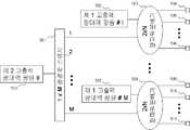
도 2는 본 발명에 따른 다수의 광선로 종단 장치들을 위한 광대역 광원의 공급 방법이다. 광대역 광원은 넓은 파장 영역에서 비간섭성 광을 발생시킨다. 광대역 광원으로는 희토류 첨가 광섬유 증폭기, 비선형 광증폭기, 반도체 광대역 광원 등이 사용된다. 광대역 광원의 출력 광파워는 펌핑광의 증가 또는 공정 향상 등을 통하여 증가 시킬 수 있다. 본 발명은 고출력 광대역 광원(200)을 이용하여 다수의 광선로 종단 장치가 공유하도록 한다. 고출력 광대역 광원(200)의 출력은 1xN 광파워 분배기(201)로 입력된다. 1xN 광파워 분배기(201)는 입력된 광을 N개의 출력단(202~204)로 분배한다. 각 출력단(202~204)는 각각 광선로 종단 장치의 광대역 광원 결합기로 입력된다. 일반적으로 광대역 광원의 광출력 증가는 비용 증가에 비해 작다. 따라서 광출력 세기를 증가시켜 분배하여 사용함으로서 각 광선로 종단 장치에 독립적으로 광대역 광원을 사용하는 것에 비해 비용이 감소하게 된다. 또한 고출력 광대역 광원(200)이 N개의 광대역 광원을 대체하므로 필요로 하는 공간을 감소시킴으로 집적도를 높일 수 있으며, 소비 전력을 감소 시킬수 있다.2 is a method of supplying a broadband light source for a plurality of optical fiber termination devices according to the present invention. Broadband light sources generate incoherent light in a wide wavelength range. As the broadband light source, a rare earth-added optical fiber amplifier, a nonlinear optical amplifier, a semiconductor broadband light source, and the like are used. The output optical power of the broadband light source can be increased by increasing the pumping light or improving the process. The present invention uses a high power
도 3은 본 발명에 따른 고출력 광대역 광원 절체의 일실시예이다. 고출력 광대역 광원의 경우 하나 또는 다수의 광가입자망을 위한 주입광을 공급하므로, 고출력 광대역 광원의 장애시 연결된 모든 가입자에 대한 서비스가 중단되는 문제가 있다. 이러한 문제에 대한 해결책하기 위해본 발명은 고출력 광대역 광원의 장애 복구 방법을 사용한다. 도 3은 제1 고출력 광대역 광원(300) 및 제 2 고출력 광대역 광원(301), 2 x N 광파워 분배기(302)로 구성된다. 제 1 고출력 광대역 광원(300)의 출력은 2 x N 광파워 분배기(302)의 제 1 입력단에 연결된다. 제 2 고출력 광대역 광원(301)의 출력은 2 x N 광파워 분배기(302)의 제 2 입력단에 연결된다. 2 x N 광파워 분배기(302)는 제 1 고출력 광대역 광원(300)의 출력광을 N 개의 출력으로 분배한다. 2 x N 광파워 분배기(302)는 제 2 고출력 광대역 광원(301)의 출력광을 N 개의 출력으로 분배한다. 광파워 분배기(302)의 각 출력단(303~305)은 광선로종단장치의 광대역 광원 결합기로 연결된다.Figure 3 is an embodiment of a high power broadband light source switching according to the present invention. In the case of the high power broadband light source, supplying the injection light for one or more optical subscriber networks, there is a problem that the service for all connected subscribers is interrupted when the high power broadband light source fails. In order to solve this problem, the present invention uses a failure recovery method of a high power broadband light source. 3 includes a first high power
제 1 고출력 광대역 광원(300)과 제 2 고출력 광대역 광원(301)을 정격 광출력으로 사용하는 경우 2 x N 광파워 분배기(302)의 각 출력단은 장애 복구 기능이 없는 구조에 비해 3 dB 더 큰 광출력을 얻을 수 있다. 만일 두개의 고출력 광대역 광원(300, 301) 중 하나가 장애를 일으킬 경우 장애 복구 기능이 없는 구조에서와 같은 광파워를 얻을 수 있다.When using the first high power
본 발명의 또 다른 사용 방법으로 평상시 제 1 고출력 광대역 광원(300)과 제 2 고출력 광대역 광원(301)의 광출력을 정격 출력의 절반으로 동작 시킨다. 이때 2 x N 광파워 분배기(302)의 각 출력단은 장애 복구 기능이 없는 구조에서와 동일한 세기의 광출력를 얻을 수 있다. 만일 두개의 고출력 광대역 광원(300, 301) 중 하나가 장애를 일으킬 경우 장애가 없는 고출력 광대역 광원의 광출력을 정격 출력으로 동작 시킴으로 장애 복구 기능이 없는 구조에서와 동일한 광출력을 얻을 수 있다.In another use method of the present invention, the light output of the first high power
도 4는 본 발명에 따른 고출력 광대역 광원 절체의 또 다른 일실시예이다.도 4는 제 1 고출력 광대역 광원(400) 및 제 2 고출력 광대역 광원(401), 2 x 1 광경로 제어기(402), 1 x N 광파워 분배기(403)로 구성된다. 제 1 고출력 광대역 광원(400)의 출력은 2 x 1 광경로 제어기(402)의 제 1 입력단에 연결된다. 제 2 고출력 광대역 광원(401)의 출력은 2 x 1 광경로 제어기(402)의 제 2 입력단에 연결된다. 2 x 1 광경로 제어기(402)는 제어 신호에 따라 광경로를 제 1 입력단과 출력단으로 설정하거나 또는 제 2 입력단과 출력단으로 설정한다. 1 x N 광파워 분배기(403)는 입력된 광을 N 개의 출력으로 분배한다. 1 x N 광파워 분배기(403)의 각 출력단(404~406)은 광선로종단장치의 광대역 광원 결합기로 연결된다.4 is another embodiment of a high power broadband light source switching in accordance with the present invention. FIG. 4 shows a first high power
2 x 1 광경로 제어기(402)의 초기 광경로는 제 1 입력단과 출력단 사이로 설정되어 제 1 고출력 광대역 광원(400)의 출력광을 1 x N 광파워 분배기(403)으로 연결한다. 만일 제 1 고출력 광대역 광원(400)에 장애가 발생하는 경우 2 x 1 광경로 제어기(402)는 광경로를 제 2 입력단과 출력단 사이로 설정하여 제 2 고출력 광대역 광원(401)의 출력광을 1 x N 광파워 분배기(403)으로 연결한다.The initial optical path of the 2 x 1
도 5는 본 발명에 따른 고출력 광대역 광원 절체의 또 다른 일실시예이다. 상술한 도 3 및 도 4에 기초한 고출력 광대역 광원의 경우 제 1 고출력 광대역 광원 이외에 장애 복구를 위한 제 2 고출력 광대역 광원을 추가로 필요하게 된다. 중앙 기지국내에는 매우 많은 수의 광선로 종단 장치를 필요로 하며, 이 경우 상술한 방법으로 1:1 또는 1+1 보호 절체를 하는 경우 많은 수의 예비 광대역 광원을 필요로 한다. 예비 광대역 광원의 수를 감소시키는 방법으로 1:M 또는 L:M 보호 절체를 할 수 있다. 도 5는 M개의 제 1 고출력 광대역 광원들(502, 507), 2 x N 광파워 분배기들 (503, 508), 하나의 제 2 고출력 광대역 광원(500), 1 x M 광경로 스위치(501)로 구성된다. i번째 제 1 고출력 광대역 광원의 출력은 i번째 2 x N 광파워 분배기의 제 1 입력단과 연결 된다. 제 2 고출력 광대역 광원(500)의 출력은 1 x M 광경로 스위치(501)의 입력단으로 연결 된다. 1 x M 광경로 스위치(501)은 제어 신호에 따라 광경로를 입력단과 M 개의 출력단중 하나의 출력단으로 설정한다. 1 x M 광경로 스위치(501)의 i번째 출력단은 i번째 2 x N 광파워 분배기의 제 2 입력단으로 연결된다. 만일 i번째 제 1 고출력 광대역 광원이 장애를 일으키는 경우 1 x M 광경로 스위치(501)의 광경로는 입력단과 i번째 출력단으로 광경로를 설정함으로써 i번째 제 1 고출력 광대역 광원장애에 의한 문제를 복구할 수 있다.Figure 5 is another embodiment of a high power broadband light source switching according to the present invention. In the case of the high power broadband light source based on FIG. 3 and FIG. 4 described above, a second high output broadband light source for fault recovery is additionally required in addition to the first high output broadband light source. In the central base station, a very large number of optical fiber termination devices are required. In this case, a large number of spare broadband light sources are required when 1: 1 or 1 + 1 protection switching is performed by the above-described method. 1: M or L: M protection switching can be achieved by reducing the number of spare broadband light sources. 5 shows M first high power
유사하게 L개의 제 2 고출력 광대역 광원과 L x M 광 경로 스위치를 이용하여 L x M 보호 절체를 수행할 수 있다.Similarly, L x M protection switching can be performed using L second high power broadband light sources and L x M optical path switches.
도 6은 본 발명에 따른 다수의 광선로 종단 장치들을 위한 광대역 광원의 또 다른 실시예이다. 도 6은 M개의 고출력 광대역 광원(600~602), M x M 광분배기(603), M 개의 1 x N 광파워 분배기(607, 608)으로 구성된다. M x M 광분배기(603)의 추가 손실을 제외한 분배 손실만을 고려할 때 M x M 광분배기(603)의 M 개의 출력단(604~606)의 광파워는 고출력 광대역 광원(600~602)의 광파워와 동일하다. 고출력 광대역 광원의 파워가 같을 때 M x M 광분배기(603)의 출력단 이후의 1 x N 광파워 분배기(607~608) 및 분배기 출력의 연결은 도 2의 상술한 구조와 같게 된다.6 is another embodiment of a broadband light source for multiple optical fiber termination devices according to the present invention. 6 is composed of M high power
도 6의 구조는 본 발명의 도 2의 구조를 M개 사용한 것에 M x M 광분배기가 추가된 형태와 유사하다. 그러나 도 6의 구조에서 M개의 고출력 광대역 광원(600~602)중 하나가 장애를 일으키는 경우 광출력단(609~614)를 통해 각 광선로 종단 장치에 입력되는 광대역 광의 세기는 1/M 만큼 감소하게 된다. 따라서 도 6의 구조는 특정 고출력 광대역 광원의 장애에 대해 전체 시스템에 끼치는 영향을 최소화 할 수 있는 장점이 있다.The structure of FIG. 6 is similar to the form in which M x M optical splitters are added to M using the structure of FIG. 2 of the present invention. However, in the structure of FIG. 6, when one of the M high power
도 6 구조의 또 다른 동작예로 고출력 광원의 정격 출력을 F/M 만큼 크게 설계/동작함으로 평상시 F/M 만큼 큰 광대역 광을 제공하고 장애 발생시에도 정상 동작이 가능하게 사용할 수 있다. 또는 고출력 광원의 정격 출력을 F/M 만큼 크게 설계하고 평상시 각 광대역 광원을 기존의 출력 정격으로 동작 시켜 광선로 종단 장치의 공급 광대역 광의 정격을 유지하고, 장애 발생시에 F/M 만큼 출력을 증가시켜 정상 동작이 가능하게 동작 시킬 수 있다.상술한 발명들의 경우 하나의 고출력 광대역 광원이 다수의 광선로종단장치를 위한 광대역 광원을 제공한다. 만일 특정 광선로 종단 장치에 광대역 광원의 공급을 차단하고 하는 경우 광파워 분배기의 출력단과 광선로 종단 장치의 광대역 광원 결합기 사이에 On/Off 광스위치를 삽입함으로 가능하다.In another operation example of FIG. 6, the rated output of the high-power light source is designed / operated as large as F / M, thereby providing broadband light as large as F / M and enabling normal operation even when a failure occurs. Alternatively, the rated output of the high-power light source is designed to be as large as F / M, and each broadband light source is normally operated at the existing output rating to maintain the rating of the supply broadband light of the line termination device, and increase the output by F / M when a failure occurs. Normal operation can be enabled. In the above-described invention, one high power broadband light source provides a broadband light source for a plurality of optical fiber terminators. If the supply of a broadband light source is cut off to a particular optical fiber terminator, it is possible to insert an on / off optical switch between the output of the optical power distributor and the broadband light source coupler of the optical fiber terminator.
도 7은 본 발명에 따른 다수의 광선로 종단 장치들을 위한 광대역 광원의 또 다른 실시예이다. 도 7은 광대역 광원(701), 1 x N 광파워 분배기(702), 다수의 광증폭기(703~705)로 구성된다. 광증폭기(703~705)의 출력단(706~708)은 광선로 종단 장치의 광대역 광원 결합기로 연결된다. 광대역 광원(701)의 광출력을 공유하고, 저가의 광증폭기를 이용하여 증폭함으로 각 광선로 종단 장치를 위한 광대역 광원의 소요 비용을 절감할 수 있다.7 is another embodiment of a broadband light source for multiple optical fiber termination devices according to the present invention. 7 is composed of a
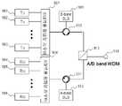
도 8은 본 발명에 따른 편광된 광대역 광원을 파장 분할 다중 방식 광대역 광원의 주입광원으로 사용하는 실시예이다. 주입광을 이용한 파장 분할 다중 방식 수동형 광가입자망의 광송수신기의 송신기로는 패브리 패롯 레이저 다이오드, 반도체 광증폭기, 또는 광변조기 등이 상용된다. 송신기에 사용된 광소자의 경우 주입광의 편광 상태에 특성이 영향을 받기도 한다. 이러한 문제를 해결하기 위한 방법으로 주입광은 편광 무의존 광원이 사용된다. 최근 반도체 기술의 발달로 반도체를 이용한 광대역 광원의 개발이 활발하다. 반도체 광대역 광원의 경우 광출력이 특정 편광 상태를 가지게 되며, 광대역 광원에서 광송수신기까지의 광경로에 따라 광송신기에 입력되는 편광 상태가 변화하게 된다. 따라서 광송신기에 임의의 편광의 주입광이 입력됨에 따라 전송 품질 저하가 발생할 수 있다. 편광된 광을 출력하는 광대역 광원을 사용하기 위해 출력광을 무편광으로 만들어 주어야 한다. 무편광 광대역 광원을 만드는 방법으로 편광된 광대역 광원(801)의 출력광을 광디폴라이져 (802: optical depolarizer)를 통과 시켜 유사 무편광 광대역 광(Quasi-unpolarized broadband light)을 얻을 수 있다. 또 다른 방법으로 두 개의 편광된 광대역 광원(804, 805)의 출력을 편광 결합기(806)에 서로 쇄교한 편광으로 입력시켜 편광 결합하여 무편광 광대역 광출력을 얻을 수 있다.8 is an embodiment using the polarized broadband light source according to the present invention as an injection light source of the wavelength division multiplex broadband light source. As a transmitter of an optical transceiver of a wavelength division multiplexing passive optical subscriber network using injected light, a Fabry parot laser diode, a semiconductor optical amplifier, or an optical modulator is commonly used. In the case of an optical element used in a transmitter, the characteristics may be affected by the polarization state of the injected light. As a method for solving this problem, a polarization independent light source is used as the injection light. Recently, due to the development of semiconductor technology, the development of broadband light sources using semiconductors is active. In the case of a semiconductor broadband light source, the light output has a specific polarization state, and the polarization state input to the optical transmitter is changed according to the optical path from the broadband light source to the optical transmitter. Therefore, transmission quality deterioration may occur as the injection light of arbitrary polarization is input to the optical transmitter. In order to use a broadband light source that outputs polarized light, the output light must be made unpolarized. A quasi-unpolarized broadband light may be obtained by passing the output light of the polarized broadband
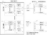
도 9 는 본 발명에 따른 광선로 종단 장치의 실시예이다. 종래 기술의 파장 분할 다중 방식의 광가입자망은 하나의 광선로에 B-대역에 하향신호를 할당하고 A-대역에 상향 신호를 할당하는 구조이다. 본 발명에 따른 광선로 종단 장치는 A 대역용 광대역 광원(912), B 대역용 광대역 광원(909), 다수의 광송신기(901~903), 다수의 광수신기(904~906), A 대역용 광파장 라우터(908), B 대역용 광파장 라우터(907), A 대역용 광써큘레이터(911), B 대역용 광써큘레이커(910), A/B 대역용 광대역 파장 분할 다중화/역다중화기(913) 및 광커넥터(914)로 구성된다. B 대역 광대역 광원(909)은 광써큘레이터(910)를 통하여 B 대역용 광파장 라우터(907)를 통하여 광송신기(901~903)에 주입광을 공급한다. 주입광을 이용하여 광송신기(901~903)에서 발생한 하향 신호들은 B 대역용 광파장 라우터(907)에서 다중화되어 광써큘레이터(910) 및 광대역 광파장 분할 다중화/역다중화기(913)을 통해 광커넥터(914)로 전달된다. 광커넥터(914)는 광선로를 통해 원격 노드와 연결된다. A 대역 광대역 광원(912)은 광써큘레이터(911) 및 광대역 광파장 분할 다중화기(913)를 통해 광커넥터, 광선로, 원격 노드를 통해 광가입자측 광송신기의 주입광을 공급하게 된다. 원격 노드에서 다중화된 상향 광신호는 광대역 광파장 분할 다중화/역다중화기(913), 광써큘레이터(911), A 대역용 광파장 라우터(908)에 의해 역다중화 되어 각각의 광수신기(904~906)으로 전달 된다.9 is an embodiment of an optical fiber termination device according to the present invention. The prior art wavelength division multiplexing optical subscriber network has a structure in which a downlink signal is assigned to a B-band and an uplink signal is assigned to an A-band in one optical path. The optical fiber terminal device according to the present invention includes a
집적도를 높이기 위해 광송신기(901~903)들을 복수의 그룹 또는 전체를 하나의 모듈로 제작하고, B 대역 광파장 라우터(907)와 집적할 수 있다. 또한 광수신기(904~906)들을 복수의 그룹 또는 전체를 하나의 모듈로 제작하고, A 대역 광파장 라우터(908)와 집적할 수 있다. 이를 구현하는 방법으로는 개별 광소자들의 모듈화를 이용하거나, 또는 평면 집적 광도파로 기술이 이용된다. 광선로 종단 장치의 일부 또는 전체의 모듈화는 중앙 기지국의 장치가 차지하는 공간을 줄이고, 저가화를 위하여 필수적이다.In order to increase the degree of integration, the
위에서 양호한 실시예에 근거하여 이 발명을 설명하였지만, 이러한 실시예는 이 발명을 제한하려는 것이 아니라 예시하려는 것이다. 이 발명이 속하는 분야의 숙련자에게는 이 발명의 기술사상을 벗어남이 없이 위 실시예에 대한 다양한 변화나 변경 또는 조절이 가능함이 자명할 것이다.
While the invention has been described above based on the preferred embodiments thereof, these embodiments are intended to illustrate rather than limit the invention. It will be apparent to those skilled in the art that various changes, modifications, or adjustments to the above embodiments can be made without departing from the spirit of the invention.
상기에서와 같이, 본 발명은 중앙 기지국에 위치하게 되는 다수의 광선로 종단 장치를 간략화할 수 있으므로, 장치가 차지하는 공간을 감소 시킬수 있다. 특히 광가입자망이 보편화 되는 경우 수많은 광선로 종단 장치를 필요하게 되며, 이러한 경우 집적도 향상은 중요한 과제가 된다. 또한 광선로 종단 장치들의 부품들을 공유함으로써 비용 절감이 가능하며, 소모 전력을 감소 시킨다.As described above, the present invention can simplify a plurality of optical fiber termination devices located at the central base station, thereby reducing the space occupied by the device. In particular, when the optical subscriber network is generalized, a number of optical fiber termination devices are required, and in this case, the integration is an important task. In addition, cost sharing is achieved by sharing the components of the fiber termination devices, which reduces power consumption.
본 발명은 다양한 형태의 광대역 광원의 장애 복구 방법들을 제공하므로, 광가입자망의 신뢰도를 향상 시킬수 있으며, 각 가입자들에게 안정된 고품질의 전송 서비스를 제공이 기대된다.
The present invention can provide various types of failure recovery methods for broadband light sources, thereby improving the reliability of the optical subscriber network and providing stable high quality transmission service to each subscriber.
Claims (16)
Translated fromKoreanPriority Applications (7)
| Application Number | Priority Date | Filing Date | Title |
|---|---|---|---|
| KR1020030034978AKR100955129B1 (en) | 2003-05-30 | 2003-05-30 | Implementation Method of Wavelength Division Multiplexing Passive Network Using Incoherent Wideband Light Source |
| EP04743852.8AEP1756977B1 (en) | 2003-05-30 | 2004-06-01 | Shared high-intensity broadband light source for wavelength-division multiple access passive optical network |
| CN200480019771XACN101180819B (en) | 2003-05-30 | 2004-06-01 | Shared high-intensity broadband light sources for wavelength division multiple access passive optical networks |
| US10/559,013US8861963B2 (en) | 2003-05-30 | 2004-06-01 | Shared high-intensity broadband light source for a wavelength-division multiple access passive optical network |
| PCT/IB2004/002187WO2006005981A2 (en) | 2003-05-30 | 2004-06-01 | Shared high-intensity broadband light source for wavelength-division multiple access passive optical network |
| JP2006524434AJP2007534197A (en) | 2003-05-30 | 2004-06-01 | Shared high-intensity broadband light source for wavelength division multiple access passive optical networks |
| JP2009045816AJP2009118532A (en) | 2003-05-30 | 2009-02-27 | Shared high-intensity broadband light source for wavelength division multiple access passive optical networks |
Applications Claiming Priority (1)
| Application Number | Priority Date | Filing Date | Title |
|---|---|---|---|
| KR1020030034978AKR100955129B1 (en) | 2003-05-30 | 2003-05-30 | Implementation Method of Wavelength Division Multiplexing Passive Network Using Incoherent Wideband Light Source |
Publications (2)
| Publication Number | Publication Date |
|---|---|
| KR20040103085A KR20040103085A (en) | 2004-12-08 |
| KR100955129B1true KR100955129B1 (en) | 2010-04-28 |
Family
ID=35784224
Family Applications (1)
| Application Number | Title | Priority Date | Filing Date |
|---|---|---|---|
| KR1020030034978AExpired - Fee RelatedKR100955129B1 (en) | 2003-05-30 | 2003-05-30 | Implementation Method of Wavelength Division Multiplexing Passive Network Using Incoherent Wideband Light Source |
Country Status (6)
| Country | Link |
|---|---|
| US (1) | US8861963B2 (en) |
| EP (1) | EP1756977B1 (en) |
| JP (2) | JP2007534197A (en) |
| KR (1) | KR100955129B1 (en) |
| CN (1) | CN101180819B (en) |
| WO (1) | WO2006005981A2 (en) |
Families Citing this family (22)
| Publication number | Priority date | Publication date | Assignee | Title |
|---|---|---|---|---|
| KR100325687B1 (en) | 1999-12-21 | 2002-02-25 | 윤덕용 | A low-cost WDM source with an incoherent light injected Fabry-Perot semiconductor laser diode |
| KR100955129B1 (en) | 2003-05-30 | 2010-04-28 | 정보통신연구진흥원 | Implementation Method of Wavelength Division Multiplexing Passive Network Using Incoherent Wideband Light Source |
| US7313157B2 (en) | 2003-12-19 | 2007-12-25 | Novera Optics, Inc. | Integration of laser sources and detectors for a passive optical network |
| KR100703409B1 (en)* | 2005-01-03 | 2007-04-03 | 삼성전자주식회사 | Broadband light source and passive optical subscriber network using the same |
| KR100720110B1 (en)* | 2005-05-20 | 2007-05-18 | 한국과학기술원 | Long-distance Transmission Wavelength Division Multiplexing Passive Optical Subscriber Network |
| KR100711201B1 (en)* | 2005-08-09 | 2007-04-24 | 한국과학기술원 | Long-distance Transmission Wavelength Division Multiplexing Passive Optical Subscriber Network Using Positioning of Broadband Incoherent Light Source |
| KR100698766B1 (en) | 2005-09-07 | 2007-03-23 | 한국과학기술원 | Obstacle location monitoring device for wavelength division multiplex passive optical subscriber network system and wavelength division multiplex passive optical subscriber network system having same |
| KR100785436B1 (en)* | 2005-09-20 | 2007-12-13 | 한국과학기술원 | Wavelength Division Multiple Passive Optical Subscriber Network Converging Broadcast Service and Communication Service |
| KR100683833B1 (en)* | 2005-12-28 | 2007-02-16 | 한국과학기술원 | Multi-Stage Divide Wavelength Division Multiple Passive Optical Subscriber Network Device Using Wavelength Allocation Method |
| US8571410B2 (en) | 2006-10-11 | 2013-10-29 | Novera Optics, Inc. | Mutual wavelength locking in WDM-PONS |
| BRPI0909474A2 (en) | 2008-03-28 | 2015-12-29 | Nortel Networks Ltd | protected light source for multiple wavelength division multiplexed passive optical networks (wdm-pons) |
| US8155523B2 (en)* | 2008-08-21 | 2012-04-10 | Lg-Ericsson Co., Ltd. | WDM PON RF overlay architecture based on quantum dot multi-wavelength laser source |
| US20100046950A1 (en)* | 2008-08-21 | 2010-02-25 | Nortel Networks Limited | Seeding wdm pon system based on quantum dot multi-wavelength laser source |
| US20100129077A1 (en)* | 2008-11-24 | 2010-05-27 | Nortel Networks Limited | Techniques for implementing a dual array waveguide filter for a wavelength division multiplexed passive optical network |
| US8644708B2 (en)* | 2009-10-21 | 2014-02-04 | Futurewei Technologies | Coupled seed light injection for wavelength division multiplexing passive optical networks |
| US20130089330A1 (en)* | 2011-10-06 | 2013-04-11 | Alcatel-Lucent Usa Inc. | Method And Apparatus For Efficient Operation Of A Passive Optical Communications Access Network |
| TWI445333B (en)* | 2012-02-29 | 2014-07-11 | Univ Nat Taiwan Science Tech | Time/wavelength-division multiplexed pon (twpon) |
| CN103516434B (en)* | 2012-06-19 | 2016-08-31 | 上海贝尔股份有限公司 | Optical sender |
| US9729950B2 (en)* | 2015-11-25 | 2017-08-08 | Google Inc. | Upgrading PON systems using a multi-cycle field AWG |
| WO2019093114A1 (en)* | 2017-11-07 | 2019-05-16 | 東洋製罐株式会社 | Synthetic resin container |
| EP3724708B1 (en)* | 2017-12-12 | 2024-03-27 | Allen Institute | Systems, apparatuses, and methods for simultaneous multi-plane imaging |
| CN114675382A (en)* | 2019-06-03 | 2022-06-28 | 华为技术有限公司 | Light source switching method and device |
Citations (3)
| Publication number | Priority date | Publication date | Assignee | Title |
|---|---|---|---|---|
| KR20000009290A (en)* | 1998-07-23 | 2000-02-15 | 윤덕용 | Wavelength division multiplexing type multiplexor/demultiplexor and wavelength division multiplexing type manual optical subscriber network by using the same |
| US20010004290A1 (en) | 1999-12-21 | 2001-06-21 | Lee Chang Hee | Low-cost WDM source with an incoherent light injected fabry-perot laser diode |
| KR20030085385A (en)* | 2002-04-30 | 2003-11-05 | 주식회사 코어세스 | Wavelength division multiplexing passive optical network system |
Family Cites Families (174)
| Publication number | Priority date | Publication date | Assignee | Title |
|---|---|---|---|---|
| US36471A (en)* | 1862-09-16 | Impfroved apparatus for evaporating amd defecating sorghum-juice | ||
| US671358A (en)* | 1899-02-04 | 1901-04-02 | Henry E Taylor | Child's shoe. |
| JPS55162640A (en)* | 1979-06-06 | 1980-12-18 | Kokusai Denshin Denwa Co Ltd <Kdd> | Light source redundancy system in optical communication |
| FR2526935A1 (en)* | 1982-05-14 | 1983-11-18 | Thomson Csf | METHOD AND DEVICE FOR SIMULTANEOUS MEASUREMENT OF GEOMETRIC CHARACTERISTICS OF AN OPTICAL FIBER |
| FR2528586A1 (en) | 1982-06-11 | 1983-12-16 | Cit Alcatel | OPTICAL SWITCHING DEVICE |
| JPS61114624U (en) | 1984-12-27 | 1986-07-19 | ||
| US4893353A (en)* | 1985-12-20 | 1990-01-09 | Yokogawa Electric Corporation | Optical frequency synthesizer/sweeper |
| US4947134A (en)* | 1987-10-30 | 1990-08-07 | American Telephone And Telegraph Company | Lightwave systems using optical amplifiers |
| US5221983A (en)* | 1989-01-19 | 1993-06-22 | Bell Communications Research, Inc. | Passive photonic loop architecture employing wavelength multiplexing |
| DE3904752A1 (en) | 1989-02-16 | 1990-08-23 | Siemens Ag | DEVICE FOR THE OPTICAL DIRECT RECEPTION OF SEVERAL WAVELENGTHS |
| DE3913300A1 (en)* | 1989-04-22 | 1990-10-25 | Standard Elektrik Lorenz Ag | OPTICAL MESSAGE TRANSMISSION SYSTEM FOR THE PARTICIPANT CONNECTION AREA |
| US5117303A (en)* | 1990-08-23 | 1992-05-26 | At&T Bell Laboratories | Method of operating concatenated optical amplifiers |
| US5523879A (en)* | 1991-04-26 | 1996-06-04 | Fuji Xerox Co., Ltd. | Optical link amplifier and a wavelength multiplex laser oscillator |
| US5408349A (en)* | 1991-07-05 | 1995-04-18 | Hitachi, Ltd. | Optical frequency division multiplexing transmission system |
| FR2682781B1 (en)* | 1991-10-16 | 1993-11-26 | France Telecom | LOGIC FUNCTION GENERATOR USING OPTICAL TRANSPOSITION IN A LASER DIODE WITH DISTRIBUTED FEEDBACK. |
| US5251054A (en) | 1991-10-24 | 1993-10-05 | General Motors Corporation | LAN electro-optical interface |
| US5251001A (en) | 1991-11-18 | 1993-10-05 | Teradyne, Inc. | Reflected optical power fiber test system |
| US5276543A (en)* | 1991-11-22 | 1994-01-04 | Gte Laboratories Incorporated | Optical signal equalizer for wavelength division multiplexed optical fiber systems |
| US5321541A (en)* | 1991-12-12 | 1994-06-14 | At&T Bell Laboratories | Passive optical communication network with broadband upgrade |
| GB9202564D0 (en)* | 1992-02-07 | 1992-03-25 | Marconi Gec Ltd | Optical signal transmission network |
| US5347525A (en)* | 1993-02-19 | 1994-09-13 | Sri International | Generation of multiple stabilized frequency references using a mode-coupled laser |
| JPH06252860A (en) | 1993-02-25 | 1994-09-09 | Kyosan Electric Mfg Co Ltd | Optical communication method and communications equipment |
| GB9311169D0 (en) | 1993-05-28 | 1993-07-14 | British Telecomm | Switching networks |
| JP2751789B2 (en)* | 1993-07-14 | 1998-05-18 | 日本電気株式会社 | Optical fiber amplifier |
| US5379309A (en)* | 1993-08-16 | 1995-01-03 | California Institute Of Technology | High frequency source having heterodyned laser oscillators injection-locked to a mode-locked laser |
| US5440417A (en) | 1993-10-04 | 1995-08-08 | At&T Corp. | System for spectrum-sliced fiber amplifier light for multi-channel wavelength-division-multiplexed applications |
| US5450417A (en)* | 1993-10-26 | 1995-09-12 | Texas Instruments Incorporated | Circuit for testing power-on-reset circuitry |
| US5412673A (en)* | 1993-12-22 | 1995-05-02 | Hoya Corporation | Single longitudinal mode laser without seeding |
| US5434662A (en)* | 1993-12-23 | 1995-07-18 | Hughes Aircraft Company | Speckle resistant method and apparatus with chirped laser beam |
| US5864414A (en)* | 1994-01-26 | 1999-01-26 | British Telecommunications Public Limited Company | WDM network with control wavelength |
| DE69534360D1 (en)* | 1994-02-17 | 2005-09-08 | Toshiba Kk | Central source of several wavelengths |
| US5600471A (en)* | 1994-04-28 | 1997-02-04 | Victor Company Of Japan, Ltd. | Optical wireless data transmission system and optical wireless data transmitting/receiving apparatus |
| US5550666A (en)* | 1994-06-17 | 1996-08-27 | Lucent Technologies Inc. | Wavelength division multiplexed multi-frequency optical source and broadband incoherent optical source |
| US5418183A (en)* | 1994-09-19 | 1995-05-23 | At&T Corp. | Method for a reflective digitally tunable laser |
| US5680234A (en) | 1994-10-20 | 1997-10-21 | Lucent Technologies Inc. | Passive optical network with bi-directional optical spectral slicing and loop-back |
| KR970008300B1 (en) | 1994-12-02 | 1997-05-22 | Korea Electronics Telecomm | Locking apparatus for multiplexing optic frequencies |
| US5907417A (en)* | 1994-12-30 | 1999-05-25 | Lucent Technologies Inc. | Passive optical network with diagnostic loop-back |
| JP3234429B2 (en)* | 1995-01-17 | 2001-12-04 | 日本電信電話株式会社 | Operation stabilizing device for mode-locked laser |
| JPH08204636A (en)* | 1995-01-25 | 1996-08-09 | Kokusai Denshin Denwa Co Ltd <Kdd> | Optical communication system |
| US5661585A (en)* | 1995-02-27 | 1997-08-26 | Lucent Technologies Inc. | Passive optical network having amplified LED transmitters |
| JP3072047B2 (en)* | 1995-03-22 | 2000-07-31 | 株式会社東芝 | WDM optical transmission device and optical repeater |
| US5625478A (en)* | 1995-09-14 | 1997-04-29 | Lucent Technologies Inc. | Optically restorable WDM ring network using simple add/drop circuitry |
| JP3751667B2 (en) | 1995-11-17 | 2006-03-01 | 富士通株式会社 | Polarization-scrambled wavelength division multiplexing signal transmission method |
| JPH09233052A (en) | 1996-02-28 | 1997-09-05 | Toshiba Corp | Optical wavelength multiplexer |
| JPH09244076A (en)* | 1996-03-08 | 1997-09-19 | Toshiba Corp | Multi-wavelength light source |
| US5936752A (en)* | 1996-05-28 | 1999-08-10 | Lucent Technologies, Inc. | WDM source for access applications |
| WO1997049248A1 (en) | 1996-06-21 | 1997-12-24 | Fiber Optic Network Systems Corp. | Wavelength division multiplexing system |
| US5812572A (en)* | 1996-07-01 | 1998-09-22 | Pacific Fiberoptics, Inc. | Intelligent fiberoptic transmitters and methods of operating and manufacturing the same |
| JP3824712B2 (en)* | 1996-07-09 | 2006-09-20 | 沖電気工業株式会社 | Light switch |
| US5835517A (en) | 1996-10-04 | 1998-11-10 | W. L. Gore & Associates, Inc. | WDM multiplexer-demultiplexer using Fabry-Perot filter array |
| JP3327148B2 (en) | 1996-11-21 | 2002-09-24 | ケイディーディーアイ株式会社 | Optical amplifier and laser light generator |
| NL1004667C2 (en)* | 1996-12-02 | 1998-06-03 | Nederland Ptt | Optical systems with one or more stabilized laser signal sources. |
| US5880865A (en)* | 1996-12-03 | 1999-03-09 | Lucent Technologies Inc. | Wavelength-division-multiplexed network having broadcast capability |
| JP2985804B2 (en)* | 1996-12-04 | 1999-12-06 | 日本電気株式会社 | Optical PLL circuit |
| US5796502A (en)* | 1997-01-06 | 1998-08-18 | Haller, Jr.; John L. | Multiple independent/dependent monochromatic light frequency fiber optic communication system and method |
| US5946331A (en) | 1997-01-17 | 1999-08-31 | Tellium, Inc. | Integrated multi-wavelength transmitter |
| DE19714650A1 (en) | 1997-04-09 | 1998-10-15 | Bosch Gmbh Robert | Access network for the transmission of optical signals |
| US6304350B1 (en) | 1997-05-27 | 2001-10-16 | Lucent Technologies Inc | Temperature compensated multi-channel, wavelength-division-multiplexed passive optical network |
| US6034799A (en)* | 1997-06-30 | 2000-03-07 | Lucent Technologies Inc. | Tuning source for lightwave systems |
| US6301031B2 (en)* | 1997-09-02 | 2001-10-09 | Agere Systems Optoelectronics Guardian Corp. | Method and apparatus for wavelength-channel tracking and alignment within an optical communications system |
| US6137611A (en) | 1997-09-27 | 2000-10-24 | Lucent Technologies Inc. | Suppression of coherent rayleigh noise in bidirectional communication systems |
| US6120190A (en)* | 1997-11-26 | 2000-09-19 | Lasertron, Inc. | Spatially variable bandpass filter monitoring and feedback control of laser wavelength especially in wavelength division multiplexing communication systems |
| DE69811963T2 (en) | 1998-01-20 | 2003-08-28 | Nortel Networks Ltd., St. Laurent | Laser arrangement for pumping optical amplifiers |
| JPH11211924A (en) | 1998-01-21 | 1999-08-06 | Nippon Telegr & Teleph Corp <Ntt> | Optical circuit for WDM communication |
| US6195200B1 (en)* | 1998-02-18 | 2001-02-27 | Lucent Technologies Inc. | High power multiwavelength light source |
| CN1174566C (en) | 1998-02-23 | 2004-11-03 | 住友电气工业株式会社 | Branch line monitoring system and branch line monitoring method |
| JPH11261532A (en)* | 1998-03-11 | 1999-09-24 | Nippon Telegr & Teleph Corp <Ntt> | WDM transmission system |
| US6650840B2 (en) | 1998-03-27 | 2003-11-18 | Lucent Technologies Inc. | Method for identifying faults in a branched optical network |
| KR100274075B1 (en) | 1998-05-09 | 2001-01-15 | 서원석 | Optical fiber grating and optical element using the same |
| US6134250A (en) | 1998-05-14 | 2000-10-17 | Lucent Technologies Inc. | Wavelength-selectable fiber ring laser |
| US6728026B2 (en)* | 1998-07-14 | 2004-04-27 | Novera Optics, Inc. | Dynamically tunable optical amplifier and fiber optic light source |
| US6141475A (en) | 1998-07-23 | 2000-10-31 | Molecular Optoelectronics Corporation | Optical waveguide with dissimilar core and cladding materials, and light emitting device employing the same |
| ATE280456T1 (en) | 1998-08-14 | 2004-11-15 | Ericsson Telefon Ab L M | WAVELENGTH CONTROL FOR WDM OPTICAL TRANSMISSION SYSTEMS |
| EP0991217A2 (en) | 1998-10-02 | 2000-04-05 | Lucent Technologies Inc. | Low cost WDM system |
| KR100345604B1 (en) | 1998-11-26 | 2002-11-13 | 엘지전자 주식회사 | Optical add/drop multiplexer for wavelength Division Multiplexed("WDM") optical networks |
| JP2000174397A (en) | 1998-12-02 | 2000-06-23 | Nec Corp | Multiple wavelength light source unit and oscillation frequency control method |
| JP2000196536A (en)* | 1998-12-28 | 2000-07-14 | Nippon Telegr & Teleph Corp <Ntt> | WDM bidirectional optical transmission system |
| JP2000310800A (en)* | 1999-02-23 | 2000-11-07 | Atr Adaptive Communications Res Lab | 2 optical signal generator |
| JP3448237B2 (en) | 1999-04-05 | 2003-09-22 | 日本電信電話株式会社 | Waveguide type optical component and optical fiber connection method |
| US6323994B1 (en) | 1999-04-12 | 2001-11-27 | Nortel Networks Limited | WDM system equalization with EDFA optical amplifiers |
| US6587261B1 (en)* | 1999-05-24 | 2003-07-01 | Corvis Corporation | Optical transmission systems including optical amplifiers and methods of use therein |
| JP2000349713A (en)* | 1999-06-03 | 2000-12-15 | Hitachi Cable Ltd | Tunable optical transmitter |
| US6498869B1 (en) | 1999-06-14 | 2002-12-24 | Xiaotian Steve Yao | Devices for depolarizing polarized light |
| KR100330209B1 (en)* | 1999-07-07 | 2002-03-25 | 윤종용 | Wideband optical fiber amplifier and amplifying method thereof |
| AU6502500A (en)* | 1999-07-27 | 2001-02-13 | New Focus, Inc. | Method and apparatus for filtering an optical beam |
| US6879619B1 (en)* | 1999-07-27 | 2005-04-12 | Intel Corporation | Method and apparatus for filtering an optical beam |
| US6178001B1 (en)* | 1999-09-08 | 2001-01-23 | Nortel Networks Limited | Method and apparatus for optical frequency modulation characterization of laser sources |
| US6307668B1 (en) | 1999-10-04 | 2001-10-23 | Optigain, Inc. | Ultra-wide bandwidth fiber based optical amplifier |
| JP2001127377A (en) | 1999-10-28 | 2001-05-11 | Hitachi Ltd | Optical transmission device and optical transmission device |
| JP2001188140A (en)* | 1999-12-28 | 2001-07-10 | Nippon Telegr & Teleph Corp <Ntt> | Opto-electric integrated circuits |
| JP3611302B2 (en) | 2000-01-06 | 2005-01-19 | 日本電信電話株式会社 | CDMA modem, CDMA communication system, and WDM / CDMA shared communication system |
| DE60039082D1 (en)* | 2000-01-06 | 2008-07-10 | Nippon Telegraph & Telephone | CDMA Encoder-Decoder, CDMA Messaging System and WDM-CDMA Messaging System |
| JP2001203643A (en) | 2000-01-21 | 2001-07-27 | Hitachi Ltd | Wavelength stabilized optical transmitter |
| US6327401B1 (en) | 2000-02-10 | 2001-12-04 | Agere Systems Optoelectronics Guardian Corp. | Multifrequency laser system |
| JP4507032B2 (en) | 2000-02-16 | 2010-07-21 | Kddi株式会社 | Bidirectional wavelength division multiplexing optical communication system |
| US6469649B1 (en) | 2000-03-08 | 2002-10-22 | Massachusetts Institute Of Technology | Narrowband analog to digital converter with suppressed second-order distortion |
| JP3505123B2 (en)* | 2000-03-21 | 2004-03-08 | 日本電信電話株式会社 | Fabrication method of photo-induced waveguide type diffraction grating |
| CA2343091C (en) | 2000-05-25 | 2009-09-08 | Kyocera Corporation | Broadband amplified spontaneous emission light source |
| US6310720B1 (en) | 2000-06-02 | 2001-10-30 | Genoa Corporation | Polarization insensitive semiconductor optical amplifier |
| JP2001356377A (en)* | 2000-06-16 | 2001-12-26 | Kdd Submarine Cable Systems Inc | Pump light generator and fiber Raman amplifier |
| KR100370097B1 (en) | 2000-07-10 | 2003-02-05 | 엘지전자 주식회사 | Apparatus for decreasing noise of Electronic Product |
| US6654401B2 (en) | 2000-08-08 | 2003-11-25 | F & H Applied Science Associates, Inc. | Multiple laser source, and systems for use thereof |
| EP1195867A1 (en) | 2000-09-04 | 2002-04-10 | Lucent Technologies Inc. | Method for wavelenght stabilization of light emission from emission devices and arrangement therefor |
| US7072588B2 (en)* | 2000-10-03 | 2006-07-04 | Halliburton Energy Services, Inc. | Multiplexed distribution of optical power |
| JP2002135212A (en)* | 2000-10-20 | 2002-05-10 | Fujitsu Ltd | Optical wavelength division multiplexing transmission system capable of bidirectional transmission |
| JP3533370B2 (en)* | 2000-11-01 | 2004-05-31 | 日本電信電話株式会社 | Trunk node device and optical access network |
| US6470036B1 (en) | 2000-11-03 | 2002-10-22 | Cidra Corporation | Tunable external cavity semiconductor laser incorporating a tunable bragg grating |
| US20020068859A1 (en)* | 2000-12-01 | 2002-06-06 | Knopp Christina A. | Laser diode drive scheme for noise reduction in photoplethysmographic measurements |
| KR100360769B1 (en)* | 2000-12-05 | 2002-11-13 | 한국전자통신연구원 | Bidirectional Optical Add/Drop Multiplexer |
| US6628696B2 (en)* | 2001-01-19 | 2003-09-30 | Siros Technologies, Inc. | Multi-channel DWDM transmitter based on a vertical cavity surface emitting laser |
| JP2002270949A (en) | 2001-03-12 | 2002-09-20 | Atr Adaptive Communications Res Lab | Optical wavelength splitting multiple signal generator |
| JP2002289971A (en)* | 2001-03-26 | 2002-10-04 | Nec Corp | Semiconductor optical element and its manufacturing method |
| US20040175188A1 (en)* | 2001-04-18 | 2004-09-09 | Antoine Bellemare | Optical sources and transmitters for optical telecommunications |
| TW525306B (en) | 2001-04-19 | 2003-03-21 | Univ Nat Taiwan | Technique using multi-layer quantum well of different widths for increasing the light emitting bandwidth of semiconductor photoelectric device |
| US20030007207A1 (en)* | 2001-04-21 | 2003-01-09 | Peter Healey | Optical signal transmitter |
| JP4703026B2 (en)* | 2001-04-26 | 2011-06-15 | 京セラ株式会社 | Broadband ASE light source |
| JP2002324641A (en) | 2001-04-26 | 2002-11-08 | Smk Corp | Thin CRT socket |
| JP3732804B2 (en) | 2001-06-13 | 2006-01-11 | 日本電信電話株式会社 | Multi-wavelength optical modulation circuit and wavelength-multiplexed optical signal transmitter |
| JP3835592B2 (en)* | 2001-06-13 | 2006-10-18 | 日本電信電話株式会社 | Optical wavelength division multiplexing transmitter |
| US20020196491A1 (en) | 2001-06-25 | 2002-12-26 | Deng Kung Li | Passive optical network employing coarse wavelength division multiplexing and related methods |
| JP2003014963A (en) | 2001-06-27 | 2003-01-15 | Nec Corp | Semiconductor optical integrated element and its manufacturing method and module for optical communication |
| JP2003017798A (en) | 2001-07-03 | 2003-01-17 | Hitachi Ltd | Optical modulator integrated light source module |
| US7254330B2 (en)* | 2001-07-20 | 2007-08-07 | Tellabs Bedford, Inc. | Single fiber passive optical network wavelength division multiplex overlay |
| CA2454631A1 (en)* | 2001-07-20 | 2003-01-30 | Essex Corporation | Method and apparatus for optical signal processing using an optical tapped delay line |
| JP2003051786A (en)* | 2001-08-06 | 2003-02-21 | Fujitsu Ltd | WDM optical transmission equipment |
| DE10138920A1 (en) | 2001-08-08 | 2003-03-06 | Siemens Ag | Method for the automated generation of at least one dialog box on a user interface of a computer user station for the graphic representation of data of a technical process plant |
| US7155127B2 (en)* | 2001-08-15 | 2006-12-26 | Nippon Telegraph And Telephone Corporation | Optical communication system, optical communication unit, and optical transceiving package |
| JP3808413B2 (en)* | 2001-08-15 | 2006-08-09 | 日本電信電話株式会社 | Optical communication system |
| US20030053174A1 (en)* | 2001-09-14 | 2003-03-20 | Harald Rosenfeldt | Optical equalizing of chromatic and polarization mode dispersion |
| KR20020003318A (en) | 2001-09-21 | 2002-01-12 | 박규식 | Method for processing business between educational companies by using internet |
| JP2003110533A (en)* | 2001-09-27 | 2003-04-11 | Fujitsu Ltd | Optical signal processing device |
| JP4006210B2 (en) | 2001-10-09 | 2007-11-14 | 日本電信電話株式会社 | Optical wavelength division multiplexing network group |
| WO2003102659A2 (en) | 2001-10-09 | 2003-12-11 | Infinera Corporation | Demultiplexing optical signal receiver photonic integrated circuit (rxpic) and associated transmitter and method of testing a photonic integrated circuit |
| US7116851B2 (en) | 2001-10-09 | 2006-10-03 | Infinera Corporation | Optical signal receiver, an associated photonic integrated circuit (RxPIC), and method improving performance |
| CA2463502C (en)* | 2001-10-09 | 2011-09-20 | Infinera Corporation | Digital optical network architecture |
| JP2003124911A (en)* | 2001-10-09 | 2003-04-25 | Nippon Telegr & Teleph Corp <Ntt> | Optical communication system |
| KR100496710B1 (en) | 2002-01-21 | 2005-06-28 | 노베라옵틱스코리아 주식회사 | Bi-directional wavelength-division-multiplexing passive optical network utilizing wavelength-locked light sources by injected incoherent light |
| KR100454887B1 (en)* | 2002-01-30 | 2004-11-06 | 한국과학기술원 | The wavelength-division multiplexed passive optical network apparatus |
| US6603599B1 (en)* | 2002-02-19 | 2003-08-05 | Finisar Corporation | Linear semiconductor optical amplifier with broad area laser |
| US7495774B2 (en) | 2002-03-01 | 2009-02-24 | Michigan Aerospace Corporation | Optical air data system |
| US7006719B2 (en)* | 2002-03-08 | 2006-02-28 | Infinera Corporation | In-wafer testing of integrated optical components in photonic integrated circuits (PICs) |
| US7403718B2 (en)* | 2002-04-24 | 2008-07-22 | Lucent Technologies Inc. | Modulation phase shift to compensate for optical passband shift |
| KR100515259B1 (en)* | 2002-05-03 | 2005-09-15 | 한국과학기술원 | Wavelength-tunable light source and wavelength-division multiplexed transmission system with the sources |
| US7075712B2 (en)* | 2002-05-30 | 2006-07-11 | Fujitsu Limited | Combining and distributing amplifiers for optical network and method |
| US20030223761A1 (en) | 2002-05-31 | 2003-12-04 | Brown Brian Robert | Embedded operational channel network management |
| US6868236B2 (en)* | 2002-07-18 | 2005-03-15 | Terabeam Corporation | Apparatus and method for combining multiple optical beams in a free-space optical communications system |
| US7254332B2 (en)* | 2002-08-06 | 2007-08-07 | Jun-Kook Choi | Wavelength division multiplexing passive optical network system |
| KR100928142B1 (en) | 2002-09-11 | 2009-11-24 | 주식회사 케이티 | WDM-PON Ray Monitoring System Using ODT |
| US7593647B2 (en)* | 2002-09-19 | 2009-09-22 | Novera Optics, Inc. | Apparatuses and methods for automatic wavelength locking of an optical transmitter to the wavelength of an injected incoherent light signal |
| KR100858277B1 (en) | 2002-09-19 | 2008-09-11 | 노베라옵틱스코리아 주식회사 | Temperature control method to automatically lock the wavelength of the Fabry-Perot laser diode to the wavelength of the injected non-coherent light |
| KR100489922B1 (en)* | 2002-10-01 | 2005-05-17 | 최준국 | Dense wavelength division multiplexing-passive optical network using self-injection locking of fabry-perot laser diode |
| WO2004034621A2 (en) | 2002-10-07 | 2004-04-22 | Novera Optics, Inc. | A wavelenght-division-multiplexing passive optical network utilizing fiber fault detectors and/or wavelenght tracking components |
| US7469102B2 (en) | 2002-10-07 | 2008-12-23 | Novera Optics, Inc. | Wavelength-division-multiplexing passive optical network utilizing fiber fault detectors and/or wavelength tracking components |
| KR100480246B1 (en)* | 2002-11-07 | 2005-04-07 | 삼성전자주식회사 | Passive optical network using loop back of multi-wavelength light generated at central office |
| KR100885879B1 (en) | 2002-11-16 | 2009-02-26 | 엘지노텔 주식회사 | High power broadband light source |
| KR100473520B1 (en)* | 2002-12-24 | 2005-03-10 | 한국과학기술원 | The optical access network using wavelength-locked WDM optical source injected by incoherent light |
| KR100516663B1 (en)* | 2003-01-02 | 2005-09-22 | 삼성전자주식회사 | Passive optical network system for simultaneous transmission of broadcasting service and switched service |
| KR100520604B1 (en)* | 2003-01-15 | 2005-10-10 | 삼성전자주식회사 | Wavelength division multiplexed light source and system for passive optical network wsing the same |
| KR100547866B1 (en)* | 2003-03-05 | 2006-01-31 | 삼성전자주식회사 | Method for maintaining wavelength lock of a Fabry-Perot laser irrespective of temperature change and wavelength-division multiplexed light source using the same |
| KR100532307B1 (en)* | 2003-03-17 | 2005-11-29 | 삼성전자주식회사 | Wavelength Division Multiplexing - Passive Optical Network for Integrating Broadcasting and Telecommunication |
| KR100532309B1 (en) | 2003-04-21 | 2005-11-29 | 삼성전자주식회사 | Method for temperature-independent injection-locking of fabry-perot lasers and wavelength division multiplexed optical source using the same |
| JP2006526307A (en) | 2003-05-29 | 2006-11-16 | ノベラ・オプティクス・インコーポレーテッド | Light source capable of laser oscillation that is wavelength-locked by the injected optical signal |
| KR100955129B1 (en) | 2003-05-30 | 2010-04-28 | 정보통신연구진흥원 | Implementation Method of Wavelength Division Multiplexing Passive Network Using Incoherent Wideband Light Source |
| KR100506201B1 (en) | 2003-06-30 | 2005-08-05 | 삼성전자주식회사 | Ethernet Passive Optical Network for Convergence of Broadcasting and Telecommunication |
| US7313157B2 (en)* | 2003-12-19 | 2007-12-25 | Novera Optics, Inc. | Integration of laser sources and detectors for a passive optical network |
| KR100566293B1 (en)* | 2004-01-02 | 2006-03-30 | 삼성전자주식회사 | Bidirectional wavelength division multiplexing self-healing passive optical subscriber network |
| KR100605899B1 (en)* | 2004-01-09 | 2006-08-02 | 삼성전자주식회사 | Wavelength Division Multiplexing Self Healing Passive Optical Subscriber Network Using Wavelength Injection |
| KR100658338B1 (en) | 2004-04-09 | 2006-12-14 | 노베라옵틱스코리아 주식회사 | Wavelength Division Multiplexing Passive Fluorescent Network with Multistage Branch Light Distribution Network |
| US7092595B2 (en)* | 2004-05-18 | 2006-08-15 | Novera Optics, Inc. | Multiple-wavelength pulsed light source for a wavelength division multiplexed passive optical network |
| KR100675834B1 (en)* | 2004-10-28 | 2007-01-29 | 한국전자통신연구원 | Loopback Wavelength Division Multiplexing Passive Optical Network |
| KR100680815B1 (en) | 2004-11-09 | 2007-02-08 | 한국과학기술원 | Optical modulation method of wavelength-fixed FPD-LD by injecting broadband incoherent light source using mutual injection of FPD-LD |
| US7627246B2 (en) | 2005-07-22 | 2009-12-01 | Novera Optics, Inc. | Wavelength division multiplexing passive optical networks to transport access platforms |
| KR100720113B1 (en) | 2005-08-29 | 2007-05-18 | 한국과학기술원 | The wavelength-division multiplexed passive optical network for reducing the degraded noise performance of wavelength-locked Fabry-Perot laser diodes |
| US8571410B2 (en)* | 2006-10-11 | 2013-10-29 | Novera Optics, Inc. | Mutual wavelength locking in WDM-PONS |
- 2003
- 2003-05-30KRKR1020030034978Apatent/KR100955129B1/ennot_activeExpired - Fee Related
- 2004
- 2004-06-01EPEP04743852.8Apatent/EP1756977B1/ennot_activeExpired - Lifetime
- 2004-06-01CNCN200480019771XApatent/CN101180819B/ennot_activeExpired - Fee Related
- 2004-06-01JPJP2006524434Apatent/JP2007534197A/enactivePending
- 2004-06-01WOPCT/IB2004/002187patent/WO2006005981A2/enactiveApplication Filing
- 2004-06-01USUS10/559,013patent/US8861963B2/ennot_activeExpired - Fee Related
- 2009
- 2009-02-27JPJP2009045816Apatent/JP2009118532A/enactivePending
Patent Citations (3)
| Publication number | Priority date | Publication date | Assignee | Title |
|---|---|---|---|---|
| KR20000009290A (en)* | 1998-07-23 | 2000-02-15 | 윤덕용 | Wavelength division multiplexing type multiplexor/demultiplexor and wavelength division multiplexing type manual optical subscriber network by using the same |
| US20010004290A1 (en) | 1999-12-21 | 2001-06-21 | Lee Chang Hee | Low-cost WDM source with an incoherent light injected fabry-perot laser diode |
| KR20030085385A (en)* | 2002-04-30 | 2003-11-05 | 주식회사 코어세스 | Wavelength division multiplexing passive optical network system |
Also Published As
| Publication number | Publication date |
|---|---|
| US20070274729A1 (en) | 2007-11-29 |
| WO2006005981A3 (en) | 2007-11-29 |
| KR20040103085A (en) | 2004-12-08 |
| JP2009118532A (en) | 2009-05-28 |
| CN101180819A (en) | 2008-05-14 |
| US8861963B2 (en) | 2014-10-14 |
| JP2007534197A (en) | 2007-11-22 |
| WO2006005981A2 (en) | 2006-01-19 |
| EP1756977B1 (en) | 2014-04-02 |
| EP1756977A2 (en) | 2007-02-28 |
| CN101180819B (en) | 2012-03-21 |
Similar Documents
| Publication | Publication Date | Title |
|---|---|---|
| KR100955129B1 (en) | Implementation Method of Wavelength Division Multiplexing Passive Network Using Incoherent Wideband Light Source | |
| KR100454887B1 (en) | The wavelength-division multiplexed passive optical network apparatus | |
| US8306422B2 (en) | WDM PON protection scheme using a dual port arrayed waveguide grating (AWG) | |
| US7634160B2 (en) | Passive optical network system based on a wavelength protection and protecting backup method thereof | |
| CN101563867B (en) | Device and method for optical line termination and optical network unit of wavelength-division multiplexed passive optical network with unknown wavelength | |
| US8538259B2 (en) | Optical access network system | |
| US8170418B2 (en) | Protected light source for multiple wavelength division multiplexed passive optical networks (WDM-PONS) | |
| US9768908B2 (en) | Protection method and optical communication system | |
| US5896474A (en) | Optical network having protection configuration | |
| CN101841746B (en) | Wavelength division multiplexing passive optical network optical line terminal having shared protection function | |
| Wang et al. | A novel centrally controlled protection scheme for traffic restoration in WDM passive optical networks | |
| US9065589B2 (en) | Apparatus and method for operating a wavelength division multiplexing access network | |
| US12328537B2 (en) | Optical communication apparatus, optical communication system and optical communication method | |
| US8644708B2 (en) | Coupled seed light injection for wavelength division multiplexing passive optical networks | |
| Kodama et al. | Wavelength collision-free and low-loss full-duplex transmission over switchable full-coupling or half-split coherent WDM-PON system with shared protection | |
| Raz et al. | Optically reconfigurable 1× 4 silicon-on-insulator remote node switch for access networks | |
| KR100628927B1 (en) | Signal Loss Compensation System of Wavelength Division Multiplexing Passive Optical Network System | |
| CN113746558A (en) | Cluster light source and method for generating cluster light source | |
| CN104243082A (en) | Large-scale optical access network system and method for realizing transmission and protection functions of broadcasting services in wavelength division multiplexing optical access network |
Legal Events
| Date | Code | Title | Description |
|---|---|---|---|
| PA0109 | Patent application | St.27 status event code:A-0-1-A10-A12-nap-PA0109 | |
| P11-X000 | Amendment of application requested | St.27 status event code:A-2-2-P10-P11-nap-X000 | |
| P13-X000 | Application amended | St.27 status event code:A-2-2-P10-P13-nap-X000 | |
| N231 | Notification of change of applicant | ||
| PN2301 | Change of applicant | St.27 status event code:A-3-3-R10-R11-asn-PN2301 St.27 status event code:A-3-3-R10-R13-asn-PN2301 | |
| R17-X000 | Change to representative recorded | St.27 status event code:A-3-3-R10-R17-oth-X000 | |
| PN2301 | Change of applicant | St.27 status event code:A-3-3-R10-R11-asn-PN2301 St.27 status event code:A-3-3-R10-R13-asn-PN2301 | |
| PN2301 | Change of applicant | St.27 status event code:A-3-3-R10-R11-asn-PN2301 St.27 status event code:A-3-3-R10-R13-asn-PN2301 | |
| PN2301 | Change of applicant | St.27 status event code:A-3-3-R10-R11-asn-PN2301 St.27 status event code:A-3-3-R10-R13-asn-PN2301 | |
| PG1501 | Laying open of application | St.27 status event code:A-1-1-Q10-Q12-nap-PG1501 | |
| R18-X000 | Changes to party contact information recorded | St.27 status event code:A-3-3-R10-R18-oth-X000 | |
| R18-X000 | Changes to party contact information recorded | St.27 status event code:A-3-3-R10-R18-oth-X000 | |
| PN2301 | Change of applicant | St.27 status event code:A-3-3-R10-R11-asn-PN2301 St.27 status event code:A-3-3-R10-R13-asn-PN2301 | |
| A201 | Request for examination | ||
| PA0201 | Request for examination | St.27 status event code:A-1-2-D10-D11-exm-PA0201 | |
| P11-X000 | Amendment of application requested | St.27 status event code:A-2-2-P10-P11-nap-X000 | |
| P13-X000 | Application amended | St.27 status event code:A-2-2-P10-P13-nap-X000 | |
| R18-X000 | Changes to party contact information recorded | St.27 status event code:A-3-3-R10-R18-oth-X000 | |
| D13-X000 | Search requested | St.27 status event code:A-1-2-D10-D13-srh-X000 | |
| D14-X000 | Search report completed | St.27 status event code:A-1-2-D10-D14-srh-X000 | |
| R17-X000 | Change to representative recorded | St.27 status event code:A-3-3-R10-R17-oth-X000 | |
| R17-X000 | Change to representative recorded | St.27 status event code:A-3-3-R10-R17-oth-X000 | |
| N231 | Notification of change of applicant | ||
| PN2301 | Change of applicant | St.27 status event code:A-3-3-R10-R11-asn-PN2301 St.27 status event code:A-3-3-R10-R13-asn-PN2301 | |
| E902 | Notification of reason for refusal | ||
| PE0902 | Notice of grounds for rejection | St.27 status event code:A-1-2-D10-D21-exm-PE0902 | |
| N231 | Notification of change of applicant | ||
| PN2301 | Change of applicant | St.27 status event code:A-3-3-R10-R11-asn-PN2301 St.27 status event code:A-3-3-R10-R13-asn-PN2301 | |
| P11-X000 | Amendment of application requested | St.27 status event code:A-2-2-P10-P11-nap-X000 | |
| P13-X000 | Application amended | St.27 status event code:A-2-2-P10-P13-nap-X000 | |
| E701 | Decision to grant or registration of patent right | ||
| PE0701 | Decision of registration | St.27 status event code:A-1-2-D10-D22-exm-PE0701 | |
| PN2301 | Change of applicant | St.27 status event code:A-3-3-R10-R11-asn-PN2301 St.27 status event code:A-3-3-R10-R13-asn-PN2301 | |
| GRNT | Written decision to grant | ||
| PR0701 | Registration of establishment | St.27 status event code:A-2-4-F10-F11-exm-PR0701 | |
| PR1002 | Payment of registration fee | Fee payment year number:1 St.27 status event code:A-2-2-U10-U11-oth-PR1002 | |
| PG1601 | Publication of registration | St.27 status event code:A-4-4-Q10-Q13-nap-PG1601 | |
| PN2301 | Change of applicant | St.27 status event code:A-5-5-R10-R11-asn-PN2301 St.27 status event code:A-5-5-R10-R13-asn-PN2301 | |
| R18-X000 | Changes to party contact information recorded | St.27 status event code:A-5-5-R10-R18-oth-X000 | |
| R18-X000 | Changes to party contact information recorded | St.27 status event code:A-5-5-R10-R18-oth-X000 | |
| PN2301 | Change of applicant | St.27 status event code:A-5-5-R10-R11-asn-PN2301 St.27 status event code:A-5-5-R10-R13-asn-PN2301 | |
| R18-X000 | Changes to party contact information recorded | St.27 status event code:A-5-5-R10-R18-oth-X000 | |
| PN2301 | Change of applicant | St.27 status event code:A-5-5-R10-R11-asn-PN2301 St.27 status event code:A-5-5-R10-R13-asn-PN2301 | |
| P22-X000 | Classification modified | St.27 status event code:A-4-4-P10-P22-nap-X000 | |
| R18-X000 | Changes to party contact information recorded | St.27 status event code:A-5-5-R10-R18-oth-X000 | |
| FPAY | Annual fee payment | Payment date:20130319 Year of fee payment:4 | |
| PR1001 | Payment of annual fee | Fee payment year number:4 St.27 status event code:A-4-4-U10-U11-oth-PR1001 | |
| R18-X000 | Changes to party contact information recorded | St.27 status event code:A-5-5-R10-R18-oth-X000 | |
| R18-X000 | Changes to party contact information recorded | St.27 status event code:A-5-5-R10-R18-oth-X000 | |
| FPAY | Annual fee payment | Payment date:20140317 Year of fee payment:5 | |
| PR1001 | Payment of annual fee | Fee payment year number:5 St.27 status event code:A-4-4-U10-U11-oth-PR1001 | |
| PN2301 | Change of applicant | St.27 status event code:A-5-5-R10-R11-asn-PN2301 St.27 status event code:A-5-5-R10-R13-asn-PN2301 | |
| R18-X000 | Changes to party contact information recorded | St.27 status event code:A-5-5-R10-R18-oth-X000 | |
| R17-X000 | Change to representative recorded | St.27 status event code:A-5-5-R10-R17-oth-X000 | |
| FPAY | Annual fee payment | Payment date:20150313 Year of fee payment:6 | |
| PR1001 | Payment of annual fee | Fee payment year number:6 St.27 status event code:A-4-4-U10-U11-oth-PR1001 | |
| LAPS | Lapse due to unpaid annual fee | ||
| PC1903 | Unpaid annual fee | Not in force date:20160421 Payment event data comment text:Termination Category : DEFAULT_OF_REGISTRATION_FEE St.27 status event code:A-4-4-U10-U13-oth-PC1903 | |
| PC1903 | Unpaid annual fee | Ip right cessation event data comment text:Termination Category : DEFAULT_OF_REGISTRATION_FEE Not in force date:20160421 St.27 status event code:N-4-6-H10-H13-oth-PC1903 | |
| R18-X000 | Changes to party contact information recorded | St.27 status event code:A-5-5-R10-R18-oth-X000 | |
| R18-X000 | Changes to party contact information recorded | St.27 status event code:A-5-5-R10-R18-oth-X000 | |
| PN2301 | Change of applicant | St.27 status event code:A-5-5-R10-R11-asn-PN2301 St.27 status event code:A-5-5-R10-R13-asn-PN2301 | |
| R18-X000 | Changes to party contact information recorded | St.27 status event code:A-5-5-R10-R18-oth-X000 | |
| R18-X000 | Changes to party contact information recorded | St.27 status event code:A-5-5-R10-R18-oth-X000 | |
| R18-X000 | Changes to party contact information recorded | St.27 status event code:A-5-5-R10-R18-oth-X000 | |
| R18-X000 | Changes to party contact information recorded | St.27 status event code:A-5-5-R10-R18-oth-X000 | |
| R18-X000 | Changes to party contact information recorded | St.27 status event code:A-5-5-R10-R18-oth-X000 | |
| R18-X000 | Changes to party contact information recorded | St.27 status event code:A-5-5-R10-R18-oth-X000 |